

Page 1

Inspiron 15 7000
2-in-1
Service Manual
Computer Model: Inspiron 15-7573
Regulatory Model: P70F
Regulatory Type: P70F001
Page 2

Notes, cautions, and warnings
NOTE: A NOTE indicates important information that helps you make
better use of your product.
CAUTION: A CAUTION indicates either potential damage to hardware or
loss of data and tells you how to avoid the problem.
WARNING: A WARNING indicates a potential for property damage,
personal injury, or death.
Copyright © 2017 Dell Inc. or its subsidiaries. All rights reserved. Dell, EMC, and other
trademarks are trademarks of Dell Inc. or its subsidiaries. Other trademarks may be
trademarks of their respective owners.
2017 - 08
Rev. A00
Page 3

Contents
Before working inside your computer........................... 10
Before you begin .....................................................................................10
Safety instructions...................................................................................10
Recommended tools.................................................................................11
Screw list................................................................................................. 12
After working inside your computer..............................14
Removing the base cover............................................. 15
Procedure................................................................................................15
Replacing the base cover..............................................17
Procedure................................................................................................ 17
Removing the battery................................................... 18
Prerequisites............................................................................................ 18
Procedure................................................................................................ 18
Replacing the battery.................................................. 20
Procedure............................................................................................... 20
Post-requisites........................................................................................ 20
Removing the hard drive...............................................21
Prerequisites............................................................................................ 21
Procedure................................................................................................ 21
3
Page 4

Replacing the hard drive.............................................. 24
Procedure................................................................................................24
Post-requisites........................................................................................ 24
Removing the solid-state drive/Intel Optane................25
Prerequisites........................................................................................... 25
Procedure............................................................................................... 25
Replacing the solid-state drive/ Intel Optane............... 27
Procedure................................................................................................27
Post-requisites........................................................................................ 28
Removing the memory modules...................................29
Prerequisites........................................................................................... 29
Procedure............................................................................................... 30
Replacing the memory modules................................... 32
Procedure................................................................................................32
Post-requisites........................................................................................ 32
Removing the coin-cell battery.................................... 33
Prerequisites............................................................................................33
Procedure................................................................................................33
Replacing the coin-cell battery.................................... 35
Procedure............................................................................................... 35
Post-requisites........................................................................................ 35
Removing the heat sink................................................36
Prerequisites........................................................................................... 36
Procedure............................................................................................... 36
4
Page 5

Replacing the heat sink................................................38
Procedure............................................................................................... 38
Post-requisites........................................................................................ 38
Removing the fan.........................................................39
Prerequisites........................................................................................... 39
Procedure............................................................................................... 39
Replacing the fan.........................................................42
Procedure................................................................................................42
Post-requisites........................................................................................ 42
Removing the speakers................................................43
Prerequisites............................................................................................43
Procedure................................................................................................43
Replacing the speakers................................................45
Procedure............................................................................................... 45
Post-requisites........................................................................................ 45
Removing the wireless card......................................... 46
Prerequisites........................................................................................... 46
Procedure............................................................................................... 46
Replacing the wireless card..........................................48
Procedure............................................................................................... 48
Post-requisites........................................................................................ 49
Removing the power-adapter port...............................50
Prerequisites........................................................................................... 50
Procedure............................................................................................... 50
5
Page 6

Replacing the power-adapter port............................... 52
Procedure............................................................................................... 52
Post-requisites........................................................................................ 52
Removing the I/O board.............................................. 53
Prerequisites........................................................................................... 53
Procedure............................................................................................... 53
Replacing the I/O board...............................................56
Procedure............................................................................................... 56
Post-requisites........................................................................................ 56
Removing the display assembly....................................57
Prerequisites............................................................................................57
Procedure................................................................................................57
Replacing the display assembly....................................60
Procedure............................................................................................... 60
Post-requisites........................................................................................ 60
Removing the system board......................................... 61
Prerequisites............................................................................................ 61
Procedure................................................................................................61
Replacing the system board.........................................65
Procedure............................................................................................... 65
Post-requisites........................................................................................ 66
Removing the status-light board.................................. 67
Prerequisites............................................................................................67
Procedure................................................................................................67
6
Page 7

Replacing the status-light board.................................. 69
Procedure............................................................................................... 69
Post-requisites........................................................................................ 69
Removing the touchpad............................................... 70
Prerequisites............................................................................................70
Procedure................................................................................................70
Replacing the touchpad............................................... 73
Procedure................................................................................................73
Post-requisites........................................................................................ 73
Removing the keyboard................................................74
Prerequisites............................................................................................74
Procedure................................................................................................75
Replacing the keyboard................................................78
Procedure................................................................................................78
Post-requisites........................................................................................ 79
Removing the palm rest...............................................80
Prerequisites........................................................................................... 80
Procedure................................................................................................ 81
Replacing the palm rest............................................... 82
Procedure................................................................................................82
Post-requisites........................................................................................ 82
7
Page 8

Downloading drivers.....................................................84
Downloading the audio driver..................................................................84
Downloading the graphics driver............................................................. 84
Downloading the USB 3.0 driver............................................................. 85
Downloading the Wi-Fi driver..................................................................85
Downloading the media-card reader driver..............................................85
Downloading the chipset driver...............................................................86
Downloading the network driver............................................................. 86
System setup...............................................................88
Boot Sequence....................................................................................... 88
Navigation keys.......................................................................................88
BIOS overview........................................................................................ 89
Entering BIOS setup program..................................................................89
System setup options..............................................................................90
System and setup password....................................................................98
Assigning a system password and setup password............................98
Deleting or changing an existing system and/or setup password...... 99
Clearing CMOS settings.................................................................. 100
Clearing forgotten passwords..........................................................100
Troubleshooting.......................................................... 101
Flashing the BIOS...................................................................................101
Enhanced Pre-Boot System Assessment (ePSA) diagnostics.................101
Running the ePSA diagnostics.........................................................102
Diagnostics............................................................................................ 102
Flea power release.................................................................................104
Wi-Fi power cycle..................................................................................104
8
Page 9

Getting help and contacting Dell................................ 105
Self-help resources................................................................................105
Contacting Dell......................................................................................106
9
Page 10

Before working inside your computer
NOTE: The images in this document may dier from your computer
depending on the conguration you ordered.
Before you begin
1 Save and close all open les and exit all open applications.
2 Shut down your computer. Click Start → Power → Shut down.
NOTE: If you are using a dierent operating system, see the
documentation of your operating system for shut-down instructions.
3 Disconnect your computer and all attached devices from their electrical outlets.
4 Disconnect all attached network devices and peripherals, such as keyboard,
mouse, and monitor from your computer.
5 Remove any media card and optical disc from your computer, if applicable.
Safety instructions
Use the following safety guidelines to protect your computer from potential damage
and ensure your personal safety.
WARNING: Before working inside your computer, read the safety
information that shipped with your computer. For more safety best
practices, see the Regulatory Compliance home page at www.dell.com/
regulatory_compliance.
WARNING: Disconnect all power sources before opening the computer
cover or panels. After you nish working inside the computer, replace all
covers, panels, and screws before connecting to the electrical outlet.
CAUTION: To avoid damaging the computer, ensure that the work surface is
at and clean.
10
Page 11

CAUTION: To avoid damaging the components and cards, handle them by
their edges, and avoid touching pins and contacts.
CAUTION: You should only perform troubleshooting and repairs as
authorized or directed by the Dell technical assistance team. Damage due to
servicing that is not authorized by Dell is not covered by your warranty. See
the safety instructions that shipped with the product or at www.dell.com/
regulatory_compliance.
CAUTION: Before touching anything inside your computer, ground yourself
by touching an unpainted metal surface, such as the metal at the back of
the computer. While you work, periodically touch an unpainted metal surface
to dissipate static electricity, which could harm internal components.
CAUTION: When you disconnect a cable, pull on its connector or on its pull
tab, not on the cable itself. Some cables have connectors with locking tabs
or thumb-screws that you must disengage before disconnecting the cable.
When disconnecting cables, keep them evenly aligned to avoid bending any
connector pins. When connecting cables, ensure that the ports and
connectors are correctly oriented and aligned.
CAUTION: Press and eject any installed card from the media-card reader.
Recommended tools
The procedures in this document may require the following tools:
• Phillips screwdriver
• Plastic scribe
11
Page 12
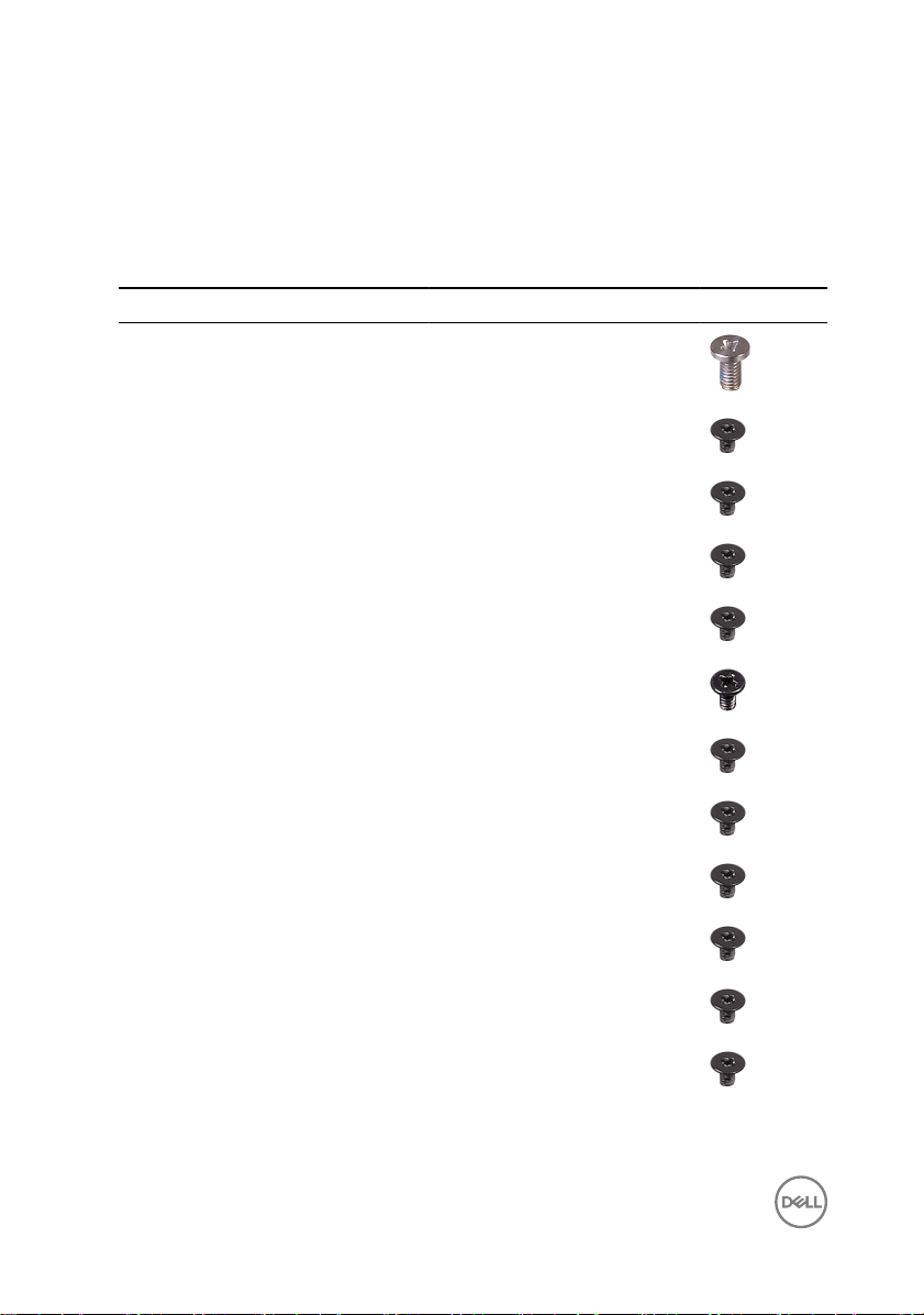
Screw list
The following table provides the list of screws that are used for securing dierent
components.
Table 1. Screw list
Component Secured to Screw type Quantity Screw image
Base cover Palm-rest
assembly
M2.5x5 4
Battery Palm-rest
assembly
Battery Keyboard shield M2x3 1
Hard-drive
assembly
Hard-drive
assembly
Hard-drive
bracket
Solid-state drive Keyboard shield M2x3 1
I/O board Palm-rest
Fan Keyboard shield M2x3 2
Wireless card I/O board M2x3 1
Power-adapter
port
USB Type-C
bracket
Palm-rest
assembly
Keyboard shield M2x3 1
Hard drive M3x3 4
assembly
Palm-rest
assembly
System board M2x3 1
M2x3 3
M2x3 2
M2x3 2
M2x3 1
12
Page 13

Component Secured to Screw type Quantity Screw image
USB Type-C
bracket
Palm-rest
assembly
M2x3 1
System board Palm-rest
assembly
System board Keyboard shield M2x2 3
Display hinges Palm-rest
assembly
Touchpad Palm-rest
assembly
Keyboard shield Palm-rest
assembly
Keyboard Palm-rest
assembly
M2x2 1
M2.5x5 7
M2x2 4
M1.4x2 26
M1.2x1.5 8
13
Page 14

After working inside your computer
CAUTION: Leaving stray or loose screws inside your computer may severely
damage your computer.
1 Replace all screws and ensure that no stray screws remain inside your computer.
2 Connect any external devices, peripherals, or cables you removed before working
on your computer.
3 Replace any media cards, discs, or any other parts that you removed before
working on your computer.
4 Connect your computer and all attached devices to their electrical outlets.
5 Turn on your computer.
14
Page 15
Removing the base cover
WARNING: Before working inside your computer, read the safety
information that shipped with your computer and follow the steps in Before
working inside your computer. After working inside your computer, follow
the instructions in After working inside your computer. For more safety best
practices, see the Regulatory Compliance home page at
regulatory_compliance.
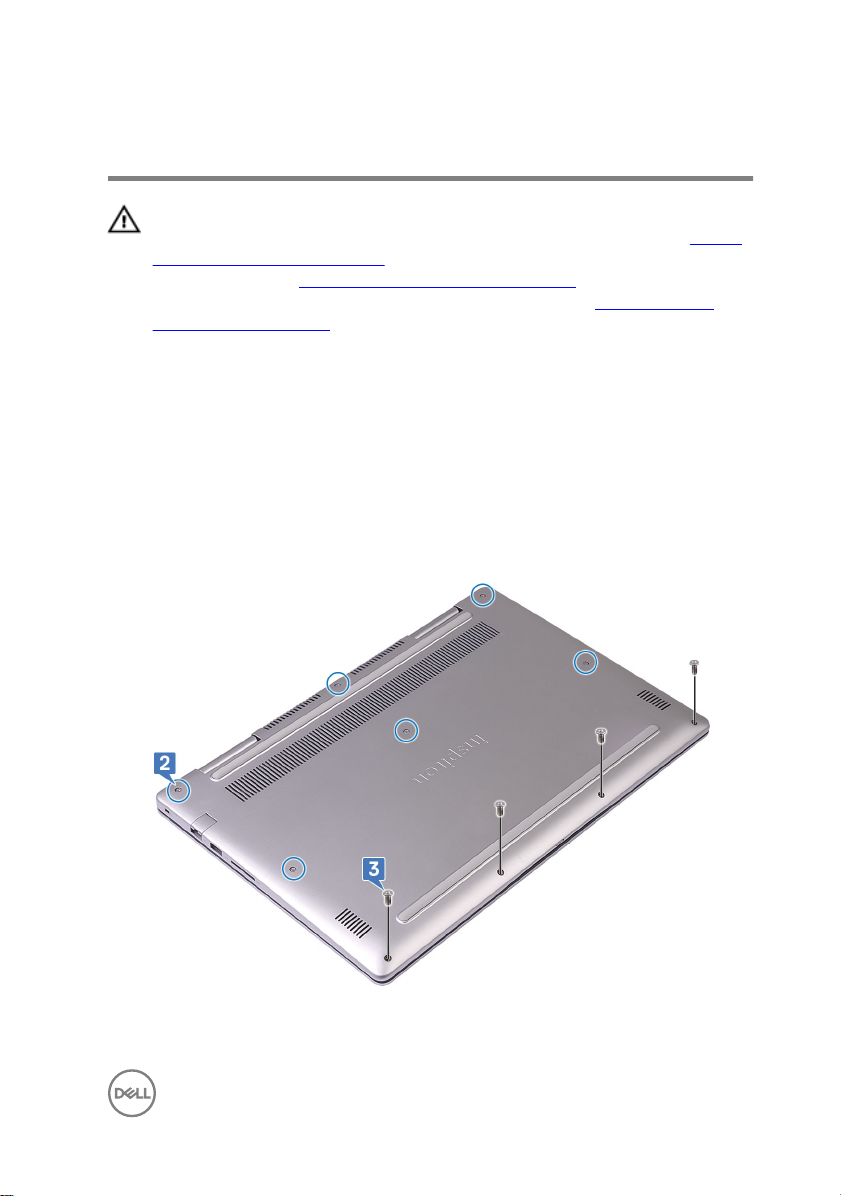
Procedure
1 Close the display and turn the computer over.
2 Loosen the six captive screws that secure the base cover to the palm-rest
assembly.
3 Remove the 4 screws (M2.5x5) that secure the base cover to the palm-rest
assembly.
www.dell.com/
15
Page 16
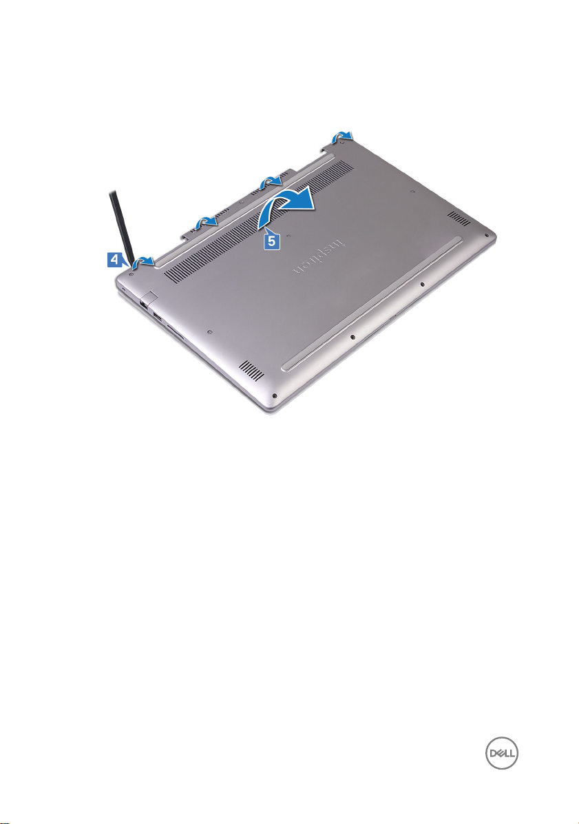
4 Using a plastic scribe, pry and release the tabs on the base cover from the slots
on the palm-rest assembly.
5 Lift the base cover from the palm-rest assembly.
6 Disconnect the battery cable from the system board.
7 Press and hold the power button for 5 seconds to ground the system board.
16
Page 17

Replacing the base cover
WARNING: Before working inside your computer, read the safety
information that shipped with your computer and follow the steps in Before
working inside your computer. After working inside your computer, follow
the instructions in After working inside your computer. For more safety best
practices, see the Regulatory Compliance home page at
regulatory_compliance.
Procedure
1 Connect the battery cable to the system board.
2 Align the tabs on the base cover with the slots on the palm-rest assembly and
snap the base cover into place.
3 Replace the four screws (M2.5x5) that secure the base cover to the palm-rest
assembly.
4 Tighten the six captive screws that secure the base cover to the palm-rest
assembly.
www.dell.com/
17
Page 18

Removing the battery
WARNING: Before working inside your computer, read the safety
information that shipped with your computer and follow the steps in Before
working inside your computer. After working inside your computer, follow
the instructions in After working inside your computer. For more safety best
practices, see the Regulatory Compliance home page at
regulatory_compliance.
Prerequisites
Remove the base cover.
Procedure
1 Using the pull tab, disconnect the battery cable from the system board.
2 Remove the four screws (M2x3) that secure the battery to the palm-rest
assembly and keyboard shield.
www.dell.com/
18
Page 19
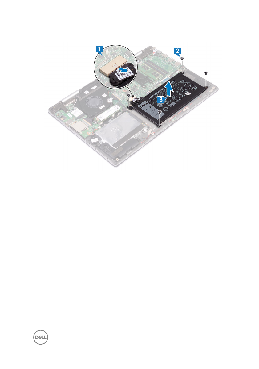
3 Lift the battery o the palm-rest assembly.
4 Turn the computer over, open the display, and press and hold the power button
for 15 seconds to ground the system board.
19
Page 20

Replacing the battery
WARNING: Before working inside your computer, read the safety
information that shipped with your computer and follow the steps in Before
working inside your computer. After working inside your computer, follow
the instructions in After working inside your computer. For more safety best
practices, see the Regulatory Compliance home page at
regulatory_compliance.
Procedure
1 Align the screw holes on the battery with the screw holes on the palm-rest
assembly and keyboard shield.
2 Replace the four screws (M2x3) that secure the battery to the palm-rest
assembly and keyboard shield.
3 Connect the battery cable to the system board.
Post-requisites
Replace the base cover.
www.dell.com/
20
Page 21

Removing the hard drive
WARNING: Before working inside your computer, read the safety
information that shipped with your computer and follow the steps in Before
working inside your computer. After working inside your computer, follow
the instructions in After working inside your computer. For more safety best
practices, see the Regulatory Compliance home page at
regulatory_compliance.
CAUTION: Hard drives are fragile. Exercise care when handling the hard
drive.
CAUTION: To avoid data loss, do not remove the hard drive while the
computer is in sleep or on state.
Prerequisites
Remove the base cover.
Procedure
1 Using the pull-tab, disconnect the hard-drive cable from the system board.
2 Remove the three screws (M2x3) that secure the hard-drive assembly to the
palm-rest assembly and keyboard shield.
www.dell.com/
21
Page 22
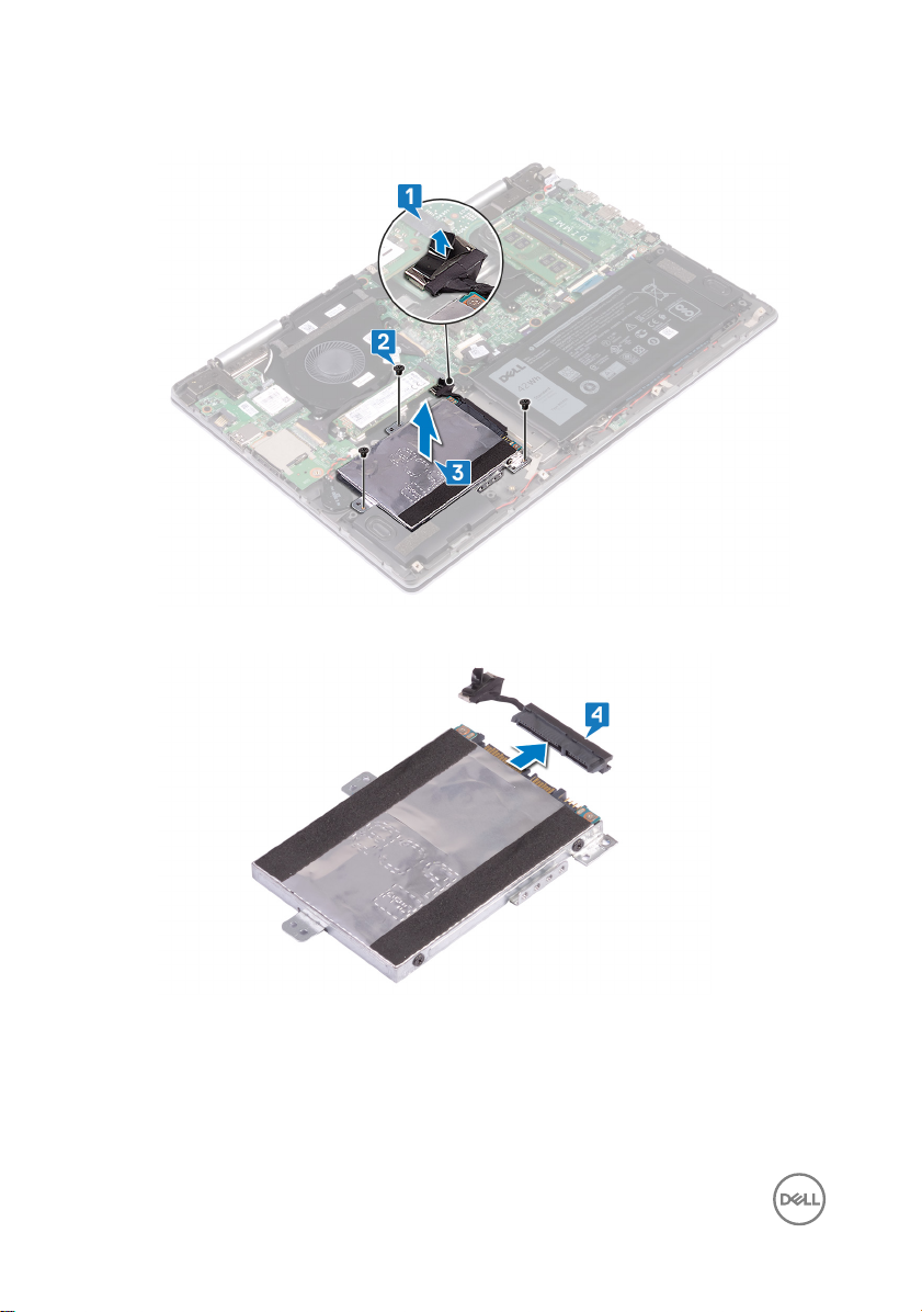
3 Lift the hard-drive assembly along with its cable o the palm-rest assembly.
4 Disconnect the interposer from the hard-drive assembly.
5 Remove the four screws (M3x3) that secure the hard-drive bracket to the hard
drive.
22
Page 23
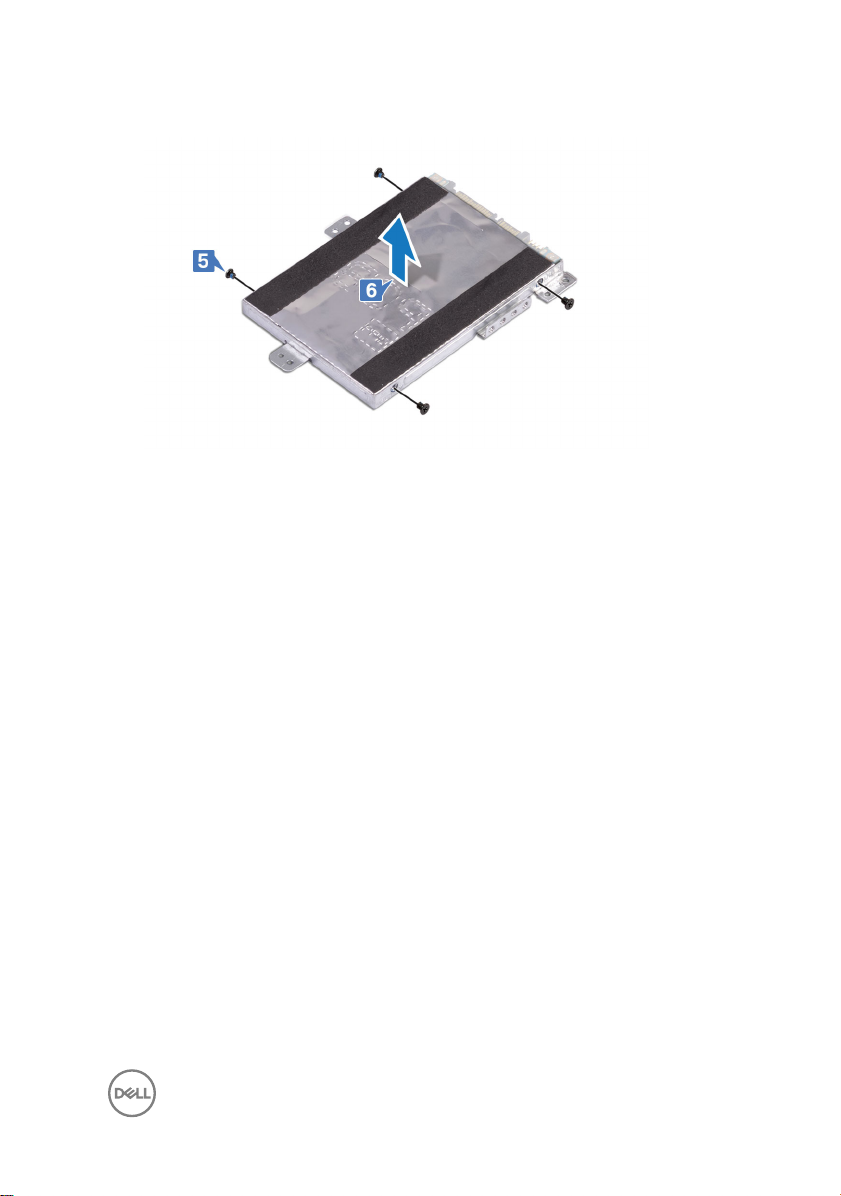
6 Remove the hard-drive bracket o the hard drive.
23
Page 24

Replacing the hard drive
WARNING: Before working inside your computer, read the safety
information that shipped with your computer and follow the steps in Before
working inside your computer. After working inside your computer, follow
the instructions in After working inside your computer. For more safety best
practices, see the Regulatory Compliance home page at
regulatory_compliance.
CAUTION: Hard drives are fragile. Exercise care when handling the hard
drive.
Procedure
1 Align the screw holes on the hard-drive bracket with the screw holes on the hard
drive.
2 Replace the four screws (M3x3) that secure the hard-drive bracket to the hard
drive.
3 Connect the interposer to the hard-drive assembly.
4 Align the screw holes on the hard-drive assembly with the screw holes on the
palm-rest assembly and keyboard shield.
5 Replace the three screws (M2x3) that secure the hard-drive assembly to the
palm-rest assembly and keyboard shield.
6 Connect the hard-drive cable to the connector on the system board.
www.dell.com/
Post-requisites
Replace the base cover.
24
Page 25
Removing the solid-state drive/ Intel Optane
WARNING: Before working inside your computer, read the safety
information that shipped with your computer and follow the steps in Before
working inside your computer. After working inside your computer, follow
the instructions in After working inside your computer. For more safety best
practices, see the Regulatory Compliance home page at
regulatory_compliance.
Prerequisites
Remove the base cover.
Procedure
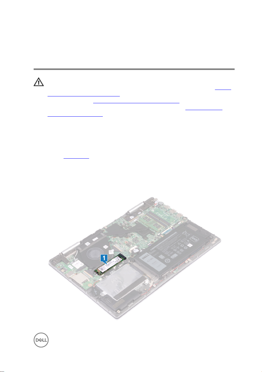
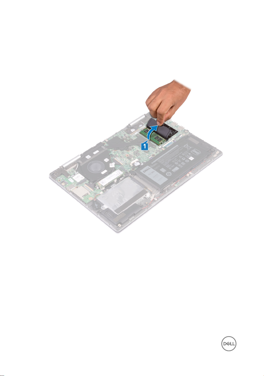
1 Locate the solid-state drive/Intel Optane memory on the system board.
www.dell.com/
25
Page 26
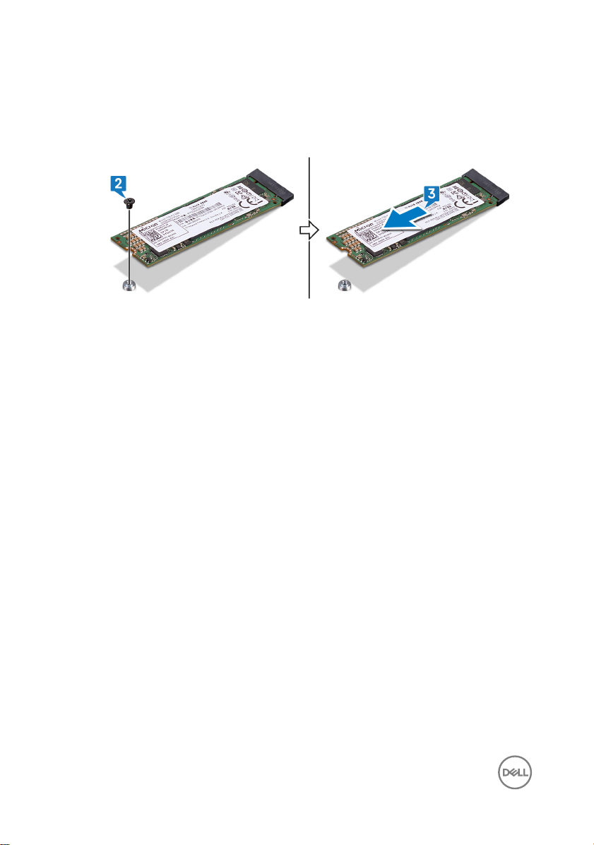
2 Remove the screw (M2x3) that secures the solid-state drive/Intel Optane
memory to the keyboard shield.
3 Slide and remove the solid-state drive/Intel Optane memory from the solid-state
drive/Intel Optane memory slot.
26
Page 27
Replacing the solid-state drive/ Intel Optane
WARNING: Before working inside your computer, read the safety
information that shipped with your computer and follow the steps in Before
working inside your computer. After working inside your computer, follow
the instructions in After working inside your computer. For more safety best
practices, see the Regulatory Compliance home page at
regulatory_compliance.
CAUTION: Solid-state drives are fragile. Exercise care when handling the
solid-state drive.
Procedure
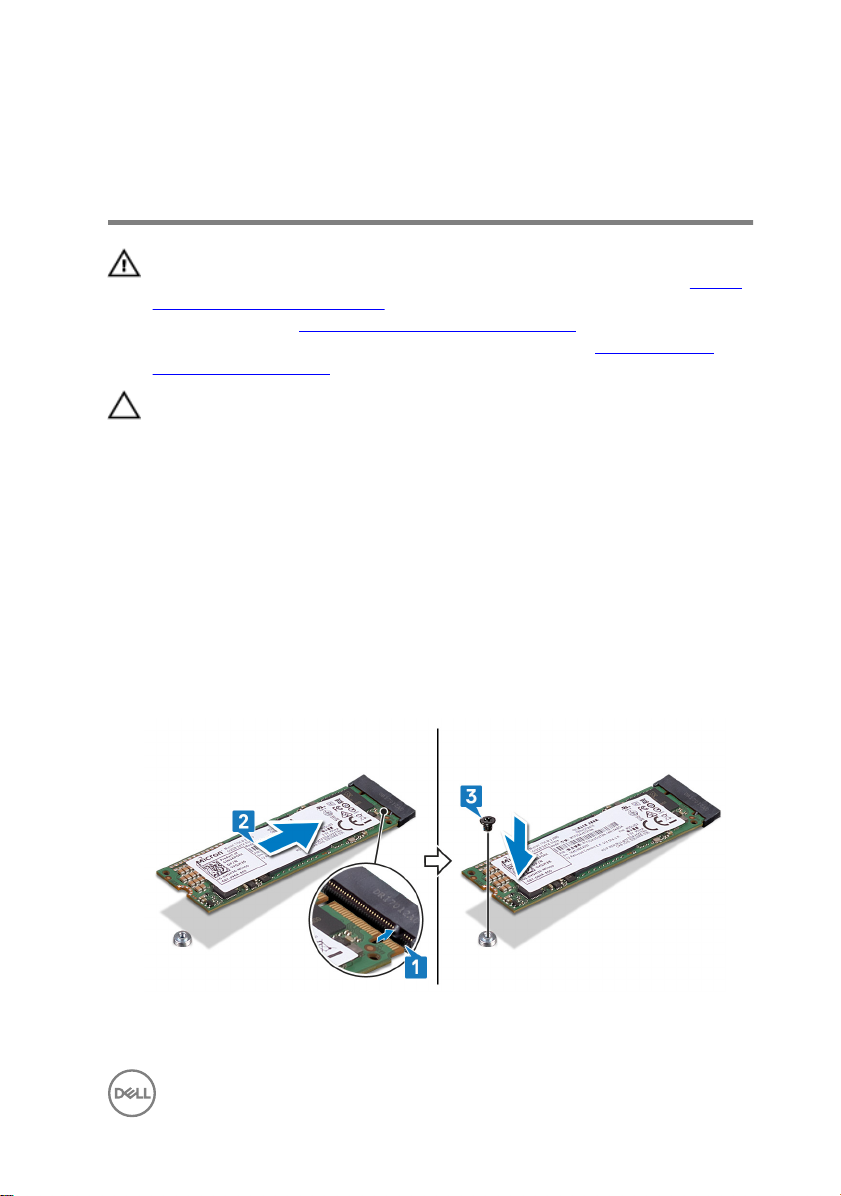
1 Align the notch on the solid-state drive/Intel Optane memory with the tab on the
solid-state drive/Intel Optane memory slot.
2 Slide the solid-state drive/Intel Optane memory rmly into the solid-state drive/
Intel Optane memory slot at an angle.
3 Press the other end of the solid-state drive/Intel Optane memory and replace
the screw (M2x3) that secures the solid-state drive/Intel Optane memory to the
keyboard shield.
www.dell.com/
27
Page 28

Post-requisites
Replace the base cover.
28
Page 29

Removing the memory modules
WARNING: Before working inside your computer, read the safety
information that shipped with your computer and follow the steps in Before
working inside your computer. After working inside your computer, follow
the instructions in After working inside your computer. For more safety best
practices, see the Regulatory Compliance home page at
regulatory_compliance.
Prerequisites
Remove the base cover.
www.dell.com/
29
Page 30
Procedure
1 Locate the memory module on the system board and lift the mylar that covers
the memory moedules.
2 Use your ngertips to carefully spread apart the securing-clips on each end of
the memory-module slot until the memory module pops up.
30
Page 31

3 Remove the memory module from the memory-module slot.
31
Page 32

Replacing the memory modules
WARNING: Before working inside your computer, read the safety
information that shipped with your computer and follow the steps in Before
working inside your computer. After working inside your computer, follow
the instructions in After working inside your computer. For more safety best
practices, see the Regulatory Compliance home page at
regulatory_compliance.
Procedure
1 Align the notch on the memory module with the tab on the memory-module slot.
2 Slide the memory module rmly into the slot at an angle.
3 Press the memory module down until it clicks into place.
NOTE: If you do not hear the click, remove the memory module and
reinstall it.
www.dell.com/
Post-requisites
Replace the base cover.
32
Page 33

Removing the coin-cell battery
WARNING: Before working inside your computer, read the safety
information that shipped with your computer and follow the steps in Before
working inside your computer. After working inside your computer, follow
the instructions in After working inside your computer. For more safety best
practices, see the Regulatory Compliance home page at
regulatory_compliance.
CAUTION: Removing the coin-cell battery resets the BIOS setup program’s
settings to default. It is recommended that you note the BIOS setup
program’s settings before removing the coin-cell battery.
Prerequisites
Remove the base cover.
Procedure
1 Disconnect the coin-cell battery cable from the I/O board.
www.dell.com/
33
Page 34

2 Peel the coin-cell battery o the palm-rest assembly.
34
Page 35

Replacing the coin-cell battery
WARNING: Before working inside your computer, read the safety
information that shipped with your computer and follow the steps in Before
working inside your computer. After working inside your computer, follow
the instructions in After working inside your computer. For more safety best
practices, see the Regulatory Compliance home page at
regulatory_compliance.
Procedure
1 Connect the coin-cell battery cable to the I/O board.
2 Adhere the coin-cell battery to the palm-rest assembly.
Post-requisites
Replace the base cover.
www.dell.com/
35
Page 36

Removing the heat sink
WARNING: Before working inside your computer, read the safety
information that shipped with your computer and follow the steps in Before
working inside your computer. After working inside your computer, follow
the instructions in After working inside your computer. For more safety best
practices, see the Regulatory Compliance home page at
regulatory_compliance.
WARNING: The heat sink may become hot during normal operation. Allow
sucient time for the heat sink to cool before you touch it.
CAUTION: For maximum cooling of the processor, do not touch the heat
transfer areas on the heat sink. The oils in your skin can reduce the heat
transfer capability of the thermal grease.
Prerequisites
Remove the base cover.
Procedure
1 In sequential order (indicated on the heat-sink), loosen the seven captive screws
that secure the heat sink to the system board.
www.dell.com/
36
NOTE: The number of screws may vary depending on the conguration
ordered.
Page 37

2 Lift the heat sink o the system board.
37
Page 38

Replacing the heat sink
WARNING: Before working inside your computer, read the safety
information that shipped with your computer and follow the steps in Before
working inside your computer. After working inside your computer, follow
the instructions in After working inside your computer. For more safety best
practices, see the Regulatory Compliance home page at
regulatory_compliance.
CAUTION: Incorrect alignment of the heat sink can damage the system
board and processor.
NOTE: The original thermal grease can be reused if the original system
board and heat sink are reinstalled together. If either the system board or
the heat sink is replaced, use the thermal pad provided in the kit to ensure
that thermal conductivity is achieved.
Procedure
1 Align the screw holes on the heat sink with the screw holes on the system board.
2 In sequential order (indicated on the heat-sink), tighten the seven captive screws
that secure the heat sink to the system board.
NOTE: The number of screws may vary depending on the conguration
ordered.
www.dell.com/
Post-requisites
Replace the base cover.
38
Page 39

Removing the fan
WARNING: Before working inside your computer, read the safety
information that shipped with your computer and follow the steps in Before
working inside your computer. After working inside your computer, follow
the instructions in After working inside your computer. For more safety best
practices, see the Regulatory Compliance home page at
regulatory_compliance.
Prerequisites
Remove the base cover.
Procedure
1 Peel the tape that secures the I/O-board cable to the system board.
2 Open the latch and disconnect the I/O-board cable from the system board.
www.dell.com/
39
Page 40

3 Remove the I/O-board cable from the routing guides on the fan.
4 Disconnect the fan cable from the system board.
5 Remove the two screws (M2x3) that secure the fan to the keyboard shield.
40
Page 41

6 Lift the fan o the palm-rest assembly.
41
Page 42

Replacing the fan
WARNING: Before working inside your computer, read the safety
information that shipped with your computer and follow the steps in Before
working inside your computer. After working inside your computer, follow
the instructions in After working inside your computer. For more safety best
practices, see the Regulatory Compliance home page at
regulatory_compliance.
Procedure
1 Using the alignment posts, place the fan on the palm-rest assembly.
2 Align the screw holes on the fan with the screw holes on the keyboard shield.
3 Replace the two screws (M2x3) that secure the fan to the keyboard shield.
4 Connect the fan cable to the system board.
5 Route the I/O-board cables through the routing guides on the fan.
6 Slide the I/O-board cable into the connector on the system board and close the
latch to secure the cable.
7 Adhere the tape that secures the I/O-board cable to the system board.
Post-requisites
www.dell.com/
Replace the base cover.
42
Page 43

Removing the speakers
WARNING: Before working inside your computer, read the safety
information that shipped with your computer and follow the steps in Before
working inside your computer. After working inside your computer, follow
the instructions in After working inside your computer. For more safety best
practices, see the Regulatory Compliance home page at
regulatory_compliance.
Prerequisites
Remove the base cover.
Procedure
1 Disconnect the speaker cable from the system board.
2 Note the position of the rubber grommets before lifting the speakers.
3 Lift the right speaker by releasing the rubber grommets from the slots on the
palm-rest assembly.
4 Lift the status-light board from the slot on the palm-rest assembly.
5 Note the cable routing and remove the speaker cable from the routing guides on
the palm-rest assembly.
www.dell.com/
43
Page 44

6 Lift the left speaker by releasing the rubber grommets from the slots on the
palm-rest assembly.
44
Page 45

Replacing the speakers
WARNING: Before working inside your computer, read the safety
information that shipped with your computer and follow the steps in Before
working inside your computer. After working inside your computer, follow
the instructions in After working inside your computer. For more safety best
practices, see the Regulatory Compliance home page at
regulatory_compliance.
Procedure
1 Using the alignment posts, align and place the left speaker on the palm-rest
assembly.
2 Replace the rubber grommets if they are pushed up while replacing the left
speaker.
3 Route the speaker cable through the routing guides on the palm-rest assembly.
4 Align and place the status-light board in the slot on the palm-rest assembly.
5 Using the alignment posts, align and place the right speaker on the palm-rest
assembly.
6 Replace the rubber grommets if they are pushed up while replacing the right
speaker.
7 Connect the speaker cable to the system board.
www.dell.com/
Post-requisites
Replace the base cover.
45
Page 46

Removing the wireless card
WARNING: Before working inside your computer, read the safety
information that shipped with your computer and follow the steps in Before
working inside your computer. After working inside your computer, follow
the instructions in After working inside your computer. For more safety best
practices, see the Regulatory Compliance home page at
regulatory_compliance.
Prerequisites
Remove the base cover.
Procedure
1 Locate the wireless card on the I/O board.
www.dell.com/
46
Page 47

2 Remove the screw (M2x3) that secures the wireless-card bracket and wireless
card to the I/O board.
3 Lift the wireless-card bracket o the wireless card.
4 Disconnect the antenna cables from the wireless card.
5 Slide and remove the wireless card from the wireless-card slot.
47
Page 48

Replacing the wireless card
WARNING: Before working inside your computer, read the safety
information that shipped with your computer and follow the steps in Before
working inside your computer. After working inside your computer, follow
the instructions in After working inside your computer. For more safety best
practices, see the Regulatory Compliance home page at
regulatory_compliance.
Procedure
CAUTION: To avoid damage to the wireless card, do not place any cables
under it.
1 Align the notch on the wireless card with the tab on the wireless-card slot and
slide the wireless card at an angle into the wireless-card slot.
2 Connect the antenna cables to the wireless card.
The following table provides the antenna-cable color scheme for the wireless
card supported by your computer.
Table 2. Antenna-cable color scheme
Connectors on the wireless card Antenna-cable color
Main (white triangle) White
www.dell.com/
Auxiliary (black triangle) Black
3 Align the screw hole on the wireless-card bracket with the screw hole on the
wireless card and the I/O board.
48
Page 49

4 Replace the screw (M2x3) that secures the wireless-card bracket and wireless
card to the I/O board.
Post-requisites
Replace the base cover.
49
Page 50

Removing the power-adapter port
WARNING: Before working inside your computer, read the safety
information that shipped with your computer and follow the steps in Before
working inside your computer. After working inside your computer, follow
the instructions in After working inside your computer. For more safety best
practices, see the Regulatory Compliance home page at
regulatory_compliance.
Prerequisites
Remove the base cover.
Procedure
1 Disconnect the power-adapter port cable from the system board.
2 Remove the screw (M2x3) that secures the power-adapter port to the palm-rest
assembly.
www.dell.com/
50
Page 51

3 Lift the power-adapter port along with its cable o the palm-rest assembly.
51
Page 52

Replacing the power-adapter port
WARNING: Before working inside your computer, read the safety
information that shipped with your computer and follow the steps in Before
working inside your computer. After working inside your computer, follow
the instructions in After working inside your computer. For more safety best
practices, see the Regulatory Compliance home page at
regulatory_compliance.
Procedure
1 Insert the power-adapter port into the slot on the palm-rest assembly.
2 Align the screw hole on the power-adapter port with the screw hole on the
palm-rest assembly.
3 Replace the screw (M2x3) that secures the power-adapter port to the palm-rest
assembly.
4 Connect the power-adapter port cable to the system board.
Post-requisites
Replace the base cover.
www.dell.com/
52
Page 53

Removing the I/O board
WARNING: Before working inside your computer, read the safety
information that shipped with your computer and follow the steps in Before
working inside your computer. After working inside your computer, follow
the instructions in After working inside your computer. For more safety best
practices, see the Regulatory Compliance home page at
regulatory_compliance.
Prerequisites
1 Remove the base cover.
2 Remove the wireless card.
Procedure
1 Peel o the tape that secures the I/O-board cable to the I/O board.
2 Open the latch and disconnect the I/O-board cable from the I/O board.
www.dell.com/
53
Page 54

3 Disconnect the coin-cell battery cable from the I/O board.
4 Remove the two screws (M2x3) that secure the I/O board to the palm-rest
assembly.
54
Page 55

5 Lift the I/O board o the palm-rest assembly.
55
Page 56

Replacing the I/O board
WARNING: Before working inside your computer, read the safety
information that shipped with your computer and follow the steps in Before
working inside your computer. After working inside your computer, follow
the instructions in After working inside your computer. For more safety best
practices, see the Regulatory Compliance home page at
regulatory_compliance.
Procedure
1 Place the I/O board on the palm-rest assembly.
2 Align the screw holes on the I/O board with the screw holes on the palm-rest
assembly.
3 Replace the two screws (M2x3) that secure the I/O board to the palm-rest
assembly.
4 Connect the coin-cell battery cable to the I/O board.
5 Slide the I/O-board cable into the connector on the I/O board and close the
latch to secure the cable.
6 Adhere the tape that secures the I/O-board cable to the I/O board.
Post-requisites
www.dell.com/
1 Replace the wireless card.
2 Replace the base cover.
56
Page 57

Removing the display assembly
WARNING: Before working inside your computer, read the safety
information that shipped with your computer and follow the steps in Before
working inside your computer. After working inside your computer, follow
the instructions in After working inside your computer. For more safety best
practices, see the Regulatory Compliance home page at
regulatory_compliance.
Prerequisites
1 Remove the base cover.
2 Remove the wireless card.
Procedure
1 Turn the computer over and open the display to 180-degree angle.
2 Place the computer on a at surface with the display facing down.
CAUTION: Place the computer on a soft and clean surface to avoid
scratching the display.
3 Peel o the tapes that secure the display cable and touch-screen board cable to
the system board.
4 Open the latches and disconnect the display cable and the touch-screen board
cable from the system board.
5 Peel o the tape that secures the antenna cables to the keyboard shield.
www.dell.com/
57
Page 58

6 Remove the antenna cables from the routing guides on the palm-rest assembly.
7 Remove the seven screws (M2.5x5) that secure the display assembly to the
palm-rest assembly.
58
Page 59

8 Lift the display assembly o the palm-rest assembly.
59
Page 60

Replacing the display assembly
WARNING: Before working inside your computer, read the safety
information that shipped with your computer and follow the steps in Before
working inside your computer. After working inside your computer, follow
the instructions in After working inside your computer. For more safety best
practices, see the Regulatory Compliance home page at
regulatory_compliance.
Procedure
CAUTION: Place the computer on a soft and clean surface to avoid
scratching the display.
1 Place the display assembly on the palm-rest assembly.
2 Align the screw holes on the display hinges with the screw holes on the palm-
rest assembly.
3 Replace the seven screws (M2.5x5) that secure the display assembly to the
palm-rest assembly.
4 Route the antenna cables through the routing guides on the palm-rest assembly.
5 Adhere the tape that secures the antenna cables to the keyboard shield.
6 Slide the display cable and the touch-screen board cable into their respective
connectors on the system board and close the latches to secure the cables.
7 Adhere the tapes that secure the display cable and the touch-screen board cable
to their respective connectors on the system board.
8 Close the display and turn the computer over.
www.dell.com/
Post-requisites
1 Replace the wireless card.
2 Replace the base cover.
60
Page 61

Removing the system board
WARNING: Before working inside your computer, read the safety
information that shipped with your computer and follow the steps in Before
working inside your computer. After working inside your computer, follow
the instructions in After working inside your computer. For more safety best
practices, see the Regulatory Compliance home page at
regulatory_compliance.
NOTE: Your computer’s Service Tag is stored in the system board. You must
enter the Service Tag in the BIOS setup program after you replace the
system board.
NOTE: Replacing the system board removes any changes you have made to
the BIOS using the BIOS setup program. You must make the appropriate
changes again after you replace the system board.
NOTE: Before disconnecting the cables from the system board, note the
location of the connectors so that you can reconnect the cables correctly
after you replace the system board.
Prerequisites
1 Remove the base cover.
2 Remove the battery.
3 Remove the solid-state drive/Intel Optane.
4 Remove the memory modules.
5 Remove the heat sink.
6 Remove the power-adapter port.
www.dell.com/
Procedure
1 Disconnect the fan cable from the system board.
2 Peel o the tapes that secure the display cable and touch-screen board cable to
the system board.
3 Open the latches and disconnect the display cable and the touch-screen board
cable from the system board.
61
Page 62

4 Peel o the tape that secures the I/O-board cable to the system board.
5 Open the latch and disconnect the I/O-board cable from the system board.
6 Using the pull tab, disconnect the hard-drive cable from the system board.
7 Open the latch and disconnect the touchpad cable from the system board.
8 Disconnect the power-adapter port cable from the system board.
9 Remove the two screws (M2x3) that secure the USB Type-C port bracket to the
system board and palm-rest assembly.
10 Lift the USB Type-C port bracket o the system board.
11 Disconnect the speaker cable from the system board.
12 Open the latch and disconnect the status-light board cable from the system
board.
13 Open the latch and disconnect the keyboard cable from the system board.
62
Page 63

14 Open the latch and disconnect the keyboard-backlight cable from the system
board.
15 Remove the four screws (M2x2) that secure the system board to the palm-rest
assembly and keyboard shield.
63
Page 64

16 Lift the system board o the palm-rest assembly.
64
Page 65

Replacing the system board
WARNING: Before working inside your computer, read the safety
information that shipped with your computer and follow the steps in Before
working inside your computer. After working inside your computer, follow
the instructions in After working inside your computer. For more safety best
practices, see the Regulatory Compliance home page at
regulatory_compliance.
NOTE: Your computer’s Service Tag is stored in the system board. You must
enter the Service Tag in the BIOS setup program after you replace the
system board.
NOTE: Replacing the system board removes any changes you have made to
the BIOS using the BIOS setup program. You must make the appropriate
changes again after you replace the system board.
Procedure
1 Align the screw holes on the system board with the screw holes on the palm-rest
assembly and keyboard shield.
2 Replace the four screws (M2x2) that secure the system board to the palm-rest
assembly and keyboard shield.
3 Slide the status-light board cable, touchpad cable, keyboard-backlight cable,
keyboard cable, I/O-board cable, display cable, and touch-screen board cable into
their respective connectors on the system baord and close the latches to secure
the cables.
4 Connect the fan cable, hard-drive cable, speaker cable and power-adapter port
cable to the system board.
5 Align the screw holes on the USB Type-C port bracket with the screw holes on
the system board.
6 Replace the two screws (M2x3) that secure the USB Type-C port bracket to the
system board.
7 Adhere the tape that secures the I/O-board cable to the system board.
8 Adhere the tapes that secure the display cable and touch-screen board cable to
their respective connectors on the system board.
www.dell.com/
65
Page 66

Post-requisites
1 Replace the power-adapter port.
2 Replace the heat sink.
3 Replace the memory modules.
4 Replace the solid-state drive/Intel Optane.
5 Replace the battery.
6 Replace the base cover.
66
Page 67

Removing the status-light board
WARNING: Before working inside your computer, read the safety
information that shipped with your computer and follow the steps in Before
working inside your computer. After working inside your computer, follow
the instructions in After working inside your computer. For more safety best
practices, see the Regulatory Compliance home page at
regulatory_compliance.
Prerequisites
1 Remove the base cover.
2 Remove the battery.
Procedure
NOTE: The status-light board includes an LED indicator for power and
battery-status light/hard-drive activity light.
1 Open the latch and disconnect the status-light board cable from the system
board.
www.dell.com/
67
Page 68

2 Lift the status-light board along with the cable o the palm-rest assembly.
68
Page 69

Replacing the status-light board
WARNING: Before working inside your computer, read the safety
information that shipped with your computer and follow the steps in Before
working inside your computer. After working inside your computer, follow
the instructions in After working inside your computer. For more safety best
practices, see the Regulatory Compliance home page at
regulatory_compliance.
Procedure
1 Align and place the status-light board in the slot on the palm-rest assembly.
2 Slide the status-light board cable into the connector on the system board and
close the latch to secure the cable.
Post-requisites
1 Replace the battery.
2 Replace the base cover.
www.dell.com/
69
Page 70

Removing the touchpad
WARNING: Before working inside your computer, read the safety
information that shipped with your computer and follow the steps in Before
working inside your computer. After working inside your computer, follow
the instructions in After working inside your computer. For more safety best
practices, see the Regulatory Compliance home page at
regulatory_compliance.
Prerequisites
1 Remove the base cover.
2 Remove the battery.
Procedure
1 Open the latch and disconnect the touchpad cable from the system board.
www.dell.com/
70
Page 71

2 Peel the tapes that secure the touchpad to the keyboard shield.
3 Remove the four screws (M2x2) that secure the touchpad to the palm rest
assembly.
71
Page 72

4 Lift the touchpad, along with the cable, at an angle from under the touch-pad
bracket o the palm-rest assembly.
72
Page 73

Replacing the touchpad
WARNING: Before working inside your computer, read the safety
information that shipped with your computer and follow the steps in Before
working inside your computer. After working inside your computer, follow
the instructions in After working inside your computer. For more safety best
practices, see the Regulatory Compliance home page at
regulatory_compliance.
Procedure
1 Align the screw holes on the touch pad with the screw holes on the palm-rest
assembly.
2 Replace the four screws (M2x2) that secure the touchpad to the palm-rest
assembly.
3 Adhere the tapes that secure the touchpad to the keyboard shield.
4 Slide the touchpad cable into the connector on the system board and close the
latch to secure the cable.
Post-requisites
1 Replace the battery.
2 Replace the base cover.
www.dell.com/
73
Page 74

Removing the keyboard
WARNING: Before working inside your computer, read the safety
information that shipped with your computer and follow the steps in Before
working inside your computer. After working inside your computer, follow
the instructions in After working inside your computer. For more safety best
practices, see the Regulatory Compliance home page at
regulatory_compliance.
Prerequisites
1 Remove the base cover.
2 Remove the battery.
3 Remove the wireless card.
4 Remove the memory modules.
5 Remove the display assembly.
6 Remove the I/O board.
7 Remove the solid-state drive/Intel Optane.
8 Remove the heat sink.
9 Remove the fan.
10 Remove the hard drive.
11 Remove the power-adapter port.
12 Remove the system board.
www.dell.com/
74
Page 75

Procedure
1 Peel o the tapes that secure the keyboard shield to the palm-rest assembly.
2 Remove the 26 screws (M1.4x2) that secure the keyboard shield and the
keyboard to the palm-rest assembly.
75
Page 76

3 Lift the keyboard shield o the keyboard.
4 Remove the eight screws (M1.2x1.5) that secure the keyboard to the palm-rest
assembly.
76
Page 77

5 Lift the keyboard o the palm-rest assembly.
77
Page 78

Replacing the keyboard
WARNING: Before working inside your computer, read the safety
information that shipped with your computer and follow the steps in Before
working inside your computer. After working inside your computer, follow
the instructions in After working inside your computer. For more safety best
practices, see the Regulatory Compliance home page at
regulatory_compliance.
Procedure
1 Place the keyboard membrane on the back of the keyboard.
2 Align the keyboard membrane with the folding line and fold the keyboard
membrane.
www.dell.com/
3 Align the screw holes on the keyboard with the screw holes on the palm-rest
assembly.
4 Replace the eight screws (M1.2x1.5) that secure the keyboard to the palm-rest
assembly.
78
Page 79

5 Place the keyboard shield onto the keyboard and align the screw holes on the
keyboard shield with the screw holes on the keyboard and the palm-rest
assembly.
6 Replace the 26 screws (M1.4x2) that secure the keyboard shield and the
keyboard to the palm-rest assembly.
7 Adhere the tapes that secure the keyboard shield to the palm-rest assembly.
Post-requisites
1 Replace the system board.
2 Replace the power-adapter port.
3 Replace the hard drive.
4 Replace the fan.
5 Replace the heat sink.
6 Replace the solid-state drive/Intel Optane.
7 Replace the I/O board.
8 Replace the display assembly.
9 Replace the memory modules.
10 Replace the wireless card.
11 Replace the battery.
12 Replace the base cover.
79
Page 80

Removing the palm rest
WARNING: Before working inside your computer, read the safety
information that shipped with your computer and follow the steps in Before
working inside your computer. After working inside your computer, follow
the instructions in After working inside your computer. For more safety best
practices, see the Regulatory Compliance home page at
regulatory_compliance.
Prerequisites
1 Remove the base cover.
2 Remove the battery.
3 Remove the coin-cell battery.
4 Remove the wireless card.
5 Remove the memory modules.
6 Remove the display assembly.
7 Remove the I/O board.
8 Remove the solid-state drive/Intel Optane.
9 Remove the heat sink.
10 Remove the fan.
11 Remove the hard drive.
12 Remove the power-adapter port.
13 Remove the system board.
14 Remove the status-light board.
15 Remove the touchpad.
16 Remove the keyboard.
www.dell.com/
80
Page 81

Procedure
After performing the steps in prerequisites, we are left with the palm rest.
81
Page 82

Replacing the palm rest
WARNING: Before working inside your computer, read the safety
information that shipped with your computer and follow the steps in Before
working inside your computer. After working inside your computer, follow
the instructions in After working inside your computer. For more safety best
practices, see the Regulatory Compliance home page at
regulatory_compliance.
Procedure
Place the palm rest on a clean and at surface.
www.dell.com/
Post-requisites
1 Replace the keyboard.
2 Replace the touchpad.
3 Replace the status-light board.
82
Page 83

4 Replace the system board.
5 Replace the power-adapter port.
6 Replace the hard drive.
7 Replace the fan.
8 Replace the heat sink.
9 Replace the solid-state drive/Intel Optane.
10 Replace the I/O board.
11 Replace the display assembly.
12 Replace the memory modules.
13 Replace the wireless card.
14 Replace the coin-cell battery.
15 Replace the battery.
16 Replace the base cover.
83
Page 84

Downloading drivers
Downloading the audio driver
1 Turn on your computer.
2 Go to www.dell.com/support.
3 Click Product Support, enter the Service Tag of your computer, and then click
Submit.
NOTE: If you do not have the Service Tag, use the auto-detect feature
or manually browse for your computer model.
4 Click Drivers & Downloads → Find it myself.
5 Scroll down the page and expand Audio.
6 Click Download to download the audio driver for your computer.
7 After the download is complete, navigate to the folder where you saved the
audio driver le.
8 Double-click the audio driver le icon and follow the instructions on the screen to
install the driver.
Downloading the graphics driver
1 Turn on your computer.
2 Go to www.dell.com/support.
3 Click Product Support, enter the Service Tag of your computer, and then click
Submit.
NOTE: If you do not have the Service Tag, use the auto-detect feature
or manually browse for your computer model.
4 Click Drivers & downloads → Find it myself.
5 Scroll down the page and expand Video.
6 Click Download to download the graphics driver for your computer.
7 After the download is complete, navigate to the folder where you saved the
graphics driver le.
8 Double-click the graphics driver le icon and follow the instructions on the
screen to install the driver.
84
Page 85

Downloading the USB 3.0 driver
1 Turn on your computer.
2 Go to www.dell.com/support.
3 Click Product Support, enter the Service Tag of your computer, and then click
Submit.
NOTE: If you do not have the Service Tag, use the auto-detect feature
or manually browse for your computer model.
4
Click Drivers & Downloads → Find it myself.
5 Scroll down the page and expand Chipset.
6 Click Download to download the USB 3.0 driver for your computer.
7 After the download is complete, navigate to the folder where you saved USB 3.0
driver le.
8 Double-click the USB 3.0 driver le icon and follow the instructions on screen to
install the driver.
Downloading the Wi-Fi driver
1 Turn on the computer.
2 Go to www.dell.com/support.
3 Click Product support, enter the Service Tag of your computer, and then click
Submit.
NOTE: If you do not have the Service Tag, use the auto-detect feature
or manually browse for your computer model.
4 Click Drivers & downloads → Find it myself.
5 Scroll down the page and expand Network.
6 Click Download to download the Wi-Fi driver for your computer.
7 After the download is complete, navigate to the folder where you saved the Wi-
Fi driver le.
8 Double-click the driver le icon and follow the instructions on the screen.
Downloading the media-card reader driver
1 Turn on your computer.
85
Page 86

2 Go to www.dell.com/support.
3 Click Product support, enter the Service Tag of your computer, and then click
Submit.
NOTE: If you do not have the Service Tag, use the auto-detect feature
or manually browse for your computer model.
4 Click Drivers & downloads → Find it myself.
5 Scroll down the page and expand Chipset.
6 Click Download to download the media-card reader driver for your computer.
7 After the download is complete, navigate to the folder where you saved the card
reader driver le.
8 Double-click the card reader driver le icon and follow the instructions on the
screen.
Downloading the chipset driver
1 Turn on your computer.
2 Go to www.dell.com/support.
3 Click Product Support, enter the Service Tag of your computer, and then click
Submit.
NOTE: If you do not have the Service Tag, use the auto-detect feature
or manually browse for your computer model.
4 Click Drivers & downloads → Find it myself.
5 Scroll down the page and expand Chipset.
6 Click Download to download the appropriate chipset driver for your computer.
7 After the download is complete, navigate to the folder where you saved the
chipset driver le.
8 Double-click the chipset driver le icon and follow the instructions on the screen
to install the driver.
Downloading the network driver
1 Turn on your computer.
2 Go to www.dell.com/support.
86
Page 87

3 Click Product support enter the Service Tag of your computer and click Submit.
NOTE: If you do not have the Service Tag, use the auto-detect feature
or manually browse for your computer model.
4 Click Drivers & downloads → Find it myself.
5 Scroll down the page and expand Network.
6 Click Download to download the network driver for your computer.
7 Save the le, and after the download is complete, navigate to the folder where
you saved the network driver le.
8 Double-click the network driver le icon and follow the instructions on screen.
87
Page 88

System setup
NOTE: Depending on the computer and its installed devices, the items listed
in this section may or may not be displayed.
Boot Sequence
Boot Sequence allows you to bypass the System Setup–dened boot device order
and boot directly to a specic device (for example: optical drive or hard drive). During
the Power-on Self Test (POST), when the Dell logo appears. you can:
• Access System Setup by pressing F2 key
• Bring up the one-time boot menu by pressing F12 key
The one-time boot menu displays the devices that you can boot from including the
diagnostic option. The boot menu options are:
• Removable Drive (if available)
• STXXXX Drive
NOTE: XXX denotes the SATA drive number.
• Optical Drive (if available)
• Diagnostics
NOTE: Choosing Diagnostics, will display the ePSA diagnostics screen.
The boot sequence screen also displays the option to access the System Setup
screen.
Navigation keys
NOTE: For most of the System Setup options, changes that you make are
recorded but do not take eect until you restart the system.
Keys
Up arrow Moves to the previous eld.
88
Navigation
Page 89

Keys Navigation
Down arrow Moves to the next eld.
Enter Selects a value in the selected eld (if applicable) or follow
the link in the eld.
Spacebar Expands or collapses a drop‐down list, if applicable.
Tab Moves to the next focus area.
NOTE: For the standard graphics browser only.
Esc Moves to the previous page until you view the main screen.
Pressing Esc in the main screen displays a message that
prompts you to save any unsaved changes and restarts the
system.
BIOS overview
CAUTION: Unless you are an expert computer user, do not change the
settings in the BIOS Setup program. Certain changes can make your
computer work incorrectly.
NOTE: Before you change BIOS Setup program, it is recommended that you
write down the BIOS Setup program screen information for future
reference.
Use the BIOS Setup program for the following purposes:
• Get information about the hardware installed in your computer, such as the
amount of RAM and the size of the hard drive.
• Change the system conguration information.
• Set or change a user-selectable option, such as the user password, type of hard
drive installed, and enabling or disabling base devices.
Entering BIOS setup program
1 Turn on (or restart) your computer.
89
Page 90

2 During POST, when the DELL logo is displayed, watch for the F2 prompt to
appear, and then press F2 immediately.
NOTE: The F2 prompt indicates that the keyboard is initialized. This
prompt can appear very quickly, so you must watch for it, and then
press F2. If you press F2 before the F2 prompt, this keystroke is lost. If
you wait too long and the operating system logo appears, continue to
wait until you see the desktop. Then, turn o your computer and try
again.
System setup options
NOTE: Depending on this computer and its installed devices, the items listed
in this section may or may not appear.
Table 3. System setup options—System information menu
General
System Information
BIOS Version Displays the BIOS version number.
Service Tag Displays the Service Tag of the computer.
Asset Tag Displays the Asset Tag of the computer.
Ownership Tag Displays the ownership tag of the computer.
Manufacture Date Displays the manufacture date of the computer.
Ownership Date Displays the ownership date of the computer.
Express Service Code Displays the express service code of the computer.
Memory Information
Memory Installed Displays the total computer memory installed.
Memory Available Displays the total computer memory available.
Memory Speed Displays the memory speed.
Memory Channel Mode Displays single or dual channel mode.
Memory Technology Displays the technology used for the memory.
DIMM A Size Displays the DIMM A memory size.
DIMM B Size Displays the DIMM B memory size.
90
Page 91

General
Processor Information
Processor Type Displays the processor type.
Core Count Displays the number of cores on the processor.
Processor ID Displays the processor identication code.
Current Clock Speed Displays the current processor clock speed.
Minimum Clock Speed Displays the minimum processor clock speed.
Maximum Clock Speed Displays the maximum processor clock speed.
Processor L2 Cache Displays the processor L2 Cache size.
Processor L3 Cache Displays the processor L3 Cache size.
HT Capable Displays whether the processor is HyperThreading
(HT) capable.
64-Bit Technology Displays whether 64-bit technology is used.
Device Information
SATA-0 Displays the SATA-0 device information of the
computer.
SATA-2 Displays the SATA-2 device information of the
computer.
M.2 PCIe SSD-0 Displays the M.2 PCIe SSD information of the
computer.
LOM MAC Address Displays the LOM MAC address of the computer.
Video Controller Displays the video controller.
Video BIOS Version Displays the video BIOS version.
Video Memory Displays the video memory.
Panel Type Displays the display panel type.
Native Resolution Displays the display resolution.
Audio Controller Displays the audio controller.
Wi-Fi Device Displays the wireless device.
Bluetooth Device Displays the bluetooth device.
91
Page 92

General
Battery Information Displays the battery health information.
Boot Sequence
Boot Sequence Displays the boot sequence.
Boot List Option Displays the available boot options.
Advanced Boot Options
Enable Legacy Option
Enable or disable the Legacy Option ROMs.
ROMs
Enable Attempt Legacy
Enable or disable Attempt Legacy Boot.
Boot
UEFI Boot Path Security Controls the security level for booting a UEFI boot
path.
Date/Time Displays the current date in MM/DD/YY format and
current time in HH:MM:SS AM/PM format.
Table 4. System setup options—System Conguration menu
System Conguration
Integrated NIC Controls the on-board LAN controller.
Enable UEFI Network
Enable or disable UEFI Network Stack.
Stack
SATA Operation Congures operating mode of the integrated SATA
hard drive controller.
Drives Enable or disable various drives on board.
SMART Reporting Enable or disable SMART Reporting during system
startup.
USB Conguration
Enable Boot Support Enable or disable booting from USB mass storage
devices such as external hard drive, optical drive,
and USB drive.
Enable External USB Port Enable or disable booting from USB mass storage
devices connected to external USB port.
92
Page 93

System Conguration
USB PowerShare Enable or disable charging external devices through
the USB PowerShare port.
Audio Enable or disable the integrated audio controller.
Keyboard Illumination Congures operating mode of the keyboard
illumination feature.
Keyboard Backlight with ACEnable or disable Keyboard Backlight with AC.
NOTE: This option does not aect Keyboard
Illumination.
Miscellaneous Devices Enable or disable various onboard devices.
Enable Camera Enable or disable the camera.
Enable Secure Digital (SD)
Enable or disable the SD card.
Card
Table 5. System setup options—Video menu
Video
LCD Brightness Set the panel brightness independently for battery
and AC power.
Table 6. System setup options—Security menu
Security
Admin Password Set, change, or delete the administrator password.
System Password Set, change, or delete the system password.
Internal HDD-2 Password Set, change, or delete the system’s internal hard-
disk drive password.
Strong Password Enable or disable strong passwords.
Password Conguration Control the minimum and maximum number of
characters allowed for Admin and System
passwords.
Password Bypass Bypass the System (Boot) Password and the
internal HDD password prompts during a system
restart.
93
Page 94

Security
Password Change Enable or disable changes to the System and Hard
Disk passwords when an administrator password is
set.
Non-Admin Setup Changes Enable or disable changes to the setup options
when an administrator password is set.
UEFI Capsule Firmware
Updates
Enable or disable BIOS updates through UEFI
capsule update packages.
PTT Security Enable or disable Platform Trust Technology (PTT)
visibility to the operating system.
Computrace(R) Enable or disable the BIOS module interface of the
optional Computrace(R) Service from Absolute
Software.
CPU XD Support Enable or disable the Execute Disable mode of the
Processor.
Admin Setup Lockout Enable to prevent users from entering Setup when
an Admin Password is set.
Master Password Lockout Enable to disable master password support.
NOTE: Hard Disk passwords need to be
cleared before the setting can be changed.
Table 7. System setup options—Secure Boot menu
Secure Boot
Secure Boot Enable Enable or disable the secure boot feature.
Expert Key Management
Expert Key Management Enable or disable Expert Key Management.
Custom Mode Key
Management
Select the custom values for expert key
management.
94
Page 95

Table 8. System setup options—Intel Software Guard Extensions menu
Intel Software Guard Extensions
Intel SGX Enable Enable or disable Intel Software Guard Extensions.
Enclave Memory Size Set the Intel Software Guard Extensions Enclave
Reserve Memory Size.
Table 9. System setup options—Performance menu
Performance
Multi Core Support Enable multiple cores.
Default: Enabled.
Intel SpeedStep Enable or disable Intel Speedstep Technology.
Default: Enabled.
NOTE: If enabled, the processor clock speed
and core voltage are adjusted dynamically
based on the processor load.
C-States Control Enable or disable additional processor sleep states.
Default: Enabled.
Intel TurboBoost Enable or disable Intel TurboBoost mode of the
processor.
Default: Enabled.
HyperThread control Enable or disable HyperThreading in the processor.
Default: Enabled.
Table 10. System setup options—Power Management menu
Power Management
Enable Intel Speed Shift
Technology
Enable or disable Intel Speed Shift Technology
support. Enables the operating system to select the
appropriate processor performance automatically.
Auto on Time Enable to set the computer to turn on automatically
every day or on a preselected date and time. This
option can be congured only if the Auto On Time is
set to Everyday, Weekdays or Selected Days.
Default: Disabled.
95
Page 96

Power Management
USB Wake Support Enable the USB devices to wake the computer from
Standby.
Wake on LAN Enable the LAN signal to wake the computer from
the o state or hibernation.
NOTE: This feature only works when the
computer is connected to AC.
Advanced Battery Charge
Conguration
Enable Advanced Battery Charge Conguration
from the beginning of the day to a specied work
period.
Primary Battery Charge
Conguration
Set the primary battery charge settings with a
preselected custom charge start and stop.
Default: Adaptive.
Table 11. System setup options—POST Behavior menu
POST Behavior
Adapter Warnings Enable adapter warnings.
Default: Enabled.
Fn Lock Options Enable or disable the Fn lock mode.
Fastboot Enable to set the speed of the boot process.
Default: Thorough.
Extended BIOS POST Time Creates an additional pre-boot delay.
Full Screen Logo Enable to display full screen logo.
Warnings and Errors Specify whether the boot process will continue or
prompt for user input when warnings and errors are
detected.
NOTE: Critical errors will always halt the
system.
96
Page 97

Table 12. System setup options—Virtualization Support menu
Virtualization Support
Virtualization Specify whether a Virtual Machine Monitor (VMM)
can utilize the additional hardware capabilities
provided by Intel Virtualization Technology.
VT for Direct I/O Specify whether a Virtual Machine Monitor (VMM)
can utilize the additional hardware capabilities
provided by Intel Virtualization Technology for Direct
I/O.
Table 13. System setup options—Wireless menu
Wireless
Wireless Switch Determine which wireless devices can be controlled
by the Wireless Switch.
Wireless Device Enable Enable or disable internal wireless devices.
Table 14. System setup options—Maintenance menu
Maintenance
Service Tag Display the computer’s Service Tag.
Asset Tag Create a computer Asset Tag.
BIOS Downgrade Control ashing of the system rmware to previous
revisions.
Data Wipe Enable to securely erase data from all internal
storage devices.
BIOS Recovery Enable the user to recover from certain corrupted
BIOS conditions from a recovery le on the user
primary hard drive or an external USB key.
Table 15. System setup options—System Logs menu
System Logs
BIOS Events Display BIOS events.
Thermal Events Display Thermal events.
97
Page 98

System Logs
Power Events Display Power events.
Table 16. System setup options—SupportAssist System Resolution menu
SupportAssist System Resolution
Auto OS Recovery
Threshold
SupportAssist OS Recovery Enable or disable the boot ow for SupportAssist
Control the automatic boot ow for SupportAssist
System Resolution Console and for Dell OS
Recovery tool.
OS Recovery tool in the even of certain system
errors.
System and setup password
You can create a system password and a setup password to secure your computer.
Password type Description
System password Password that you must enter to log on to your system.
Setup password Password that you must enter to access and make changes
to the BIOS settings of your computer.
CAUTION: The password features provide a basic level of security for the
data on your computer.
CAUTION: Anyone can access the data stored on your computer if it is not
locked and left unattended.
NOTE: Your computer is shipped with the system and setup password
feature is disabled.
Assigning a system password and setup password
You can assign a new System Password only when the status is in Not Set.
To enter the system setup, press F2 immediately after a power-on or re-boot.
1 In the System BIOS or System Setup screen, select Security and press Enter.
The Security screen is displayed.
98
Page 99

2 Select System Password and create a password in the Enter the new password
eld.
Use the following guidelines to assign the system password:
– A password can have up to 32 characters.
– The password can contain the numbers 0 through 9.
– Only lower case letters are valid, upper case letters are not allowed.
– Only the following special characters are allowed: space, (”), (+), (,), (-), (.),
(/), (;), ([), (\), (]), (`).
3 Type the system password that you entered earlier in the Conrm new
password eld and click OK.
4 Press Esc and a message prompts you to save the changes.
5 Press Y to save the changes.
The computer reboots.
Deleting or changing an existing system and/or setup password
Ensure that the Password Status is Unlocked (in the System Setup) before
attempting to delete or change the existing System and/or Setup password. You
cannot delete or change an existing System or Setup password, if the
Status is Locked.
To enter the System Setup, press F2 immediately after a power-on or reboot.
1 In the System BIOS or System Setup screen, select System Security and press
Enter.
The System Security screen is displayed.
2 In the System Security screen, verify that Password Status is Unlocked.
3 Select System Password, alter or delete the existing system password and press
Enter or Tab.
4 Select Setup Password, alter or delete the existing setup password and press
Enter or Tab.
Password
NOTE: If you change the System and/or Setup password, re-enter the
new password when promoted. If you delete the System and/or Setup
password, conrm the deletion when promoted.
5 Press Esc and a message prompts you to save the changes.
6 Press Y to save the changes and exit from System Setup.
The computer reboots.
99
Page 100

Clearing CMOS settings
CAUTION: Clearing CMOS settings will reset the BIOS settings on your
computer.
1 Remove the base cover.
2 Remove the battery.
3 Disconnect the coin-cell battery.
4 Wait for one minute.
5 Connect the coin-cell battery.
6 Replace the battery.
7 Replace the base cover.
Clearing forgotten passwords
Contact Dell technical support to clear the forgotten passwords, see www.dell.com/
contactdell.
100
 Loading...