

Dell Inspiron 5565 Service manual

Inspiron 15 5000
Service Manual
Computer Model: Inspiron 15-5565
Regulatory Model: P66F
Regulatory Type: P66F002/P66F003
Notes, cautions, and warnings
NOTE: A NOTE indicates important information that helps you make
better use of your product.
CAUTION: A CAUTION indicates either potential damage to hardware or
loss of data and tells you how to avoid the problem.
WARNING: A WARNING indicates a potential for property damage,
personal injury, or death.
Copyright © 2017 Dell Inc. or its subsidiaries. All rights reserved. Dell, EMC, and other
trademarks are trademarks of Dell Inc. or its subsidiaries. Other trademarks may be
trademarks of their respective owners.
2017 - 02
Rev. A02

Contents
Before working inside your computer........................... 10
Before you begin .....................................................................................10
Safety instructions...................................................................................10
Recommended tools.................................................................................11
Screw list................................................................................................. 12
After working inside your computer..............................14
Removing the optical drive........................................... 15
Procedure................................................................................................15
Replacing the optical drive........................................... 19
Procedure................................................................................................19
Removing the base cover.............................................20
Prerequisites........................................................................................... 20
Procedure................................................................................................ 21
Replacing the base cover............................................. 24
Procedure................................................................................................24
Post-requisites........................................................................................ 25
Removing the memory modules................................... 26
Prerequisites............................................................................................26
Procedure............................................................................................... 26
3

Replacing the memory modules................................... 28
Procedure................................................................................................28
Post-requisites........................................................................................ 30
Removing the wireless card.......................................... 31
Prerequisites............................................................................................ 31
Procedure................................................................................................ 31
Replacing the wireless card..........................................33
Procedure................................................................................................33
Post-requisites........................................................................................ 35
Removing the optical-drive interposer......................... 36
Prerequisites........................................................................................... 36
Procedure............................................................................................... 36
Replacing the optical-drive interposer......................... 38
Procedure............................................................................................... 38
Post-requisites........................................................................................ 38
Removing the coin-cell battery.................................... 39
Prerequisites........................................................................................... 39
Procedure............................................................................................... 39
Replacing the coin-cell battery.....................................41
Procedure................................................................................................ 41
Post-requisites......................................................................................... 41
Removing the I/O board...............................................42
Prerequisites............................................................................................42
Procedure................................................................................................42
4

Replacing the I/O board...............................................44
Procedure................................................................................................44
Post-requisites........................................................................................ 44
Removing the hard drive.............................................. 45
Prerequisites........................................................................................... 45
Procedure............................................................................................... 45
Replacing the hard drive.............................................. 48
Procedure............................................................................................... 48
Post-requisites........................................................................................ 48
Removing the battery.................................................. 49
Prerequisites........................................................................................... 49
Procedure............................................................................................... 49
Replacing the battery.................................................. 52
Procedure............................................................................................... 52
Post-requisites........................................................................................ 52
Removing the status-light board..................................53
Prerequisites........................................................................................... 53
Procedure............................................................................................... 53
Replacing the status-light board.................................. 55
Procedure............................................................................................... 55
Post-requisites........................................................................................ 55
Removing the speakers................................................56
Prerequisites........................................................................................... 56
Procedure............................................................................................... 56
5

Replacing the speakers................................................58
Procedure............................................................................................... 58
Post-requisites........................................................................................ 58
Removing the system-board assembly.........................59
Prerequisites........................................................................................... 59
Procedure............................................................................................... 60
Replacing the system-board assembly......................... 64
Procedure............................................................................................... 64
Post-requisites........................................................................................ 65
Removing the heat-sink assembly................................66
Prerequisites........................................................................................... 66
Procedure................................................................................................67
Replacing the heat-sink assembly................................68
Procedure............................................................................................... 68
Post-requisites........................................................................................ 68
Removing the touch pad.............................................. 70
Prerequisites............................................................................................70
Procedure................................................................................................70
Replacing the touch pad...............................................74
Procedure................................................................................................74
Post-requisites........................................................................................ 75
Removing the display assembly....................................76
Prerequisites............................................................................................76
Procedure................................................................................................76
6

Replacing the display assembly....................................80
Procedure............................................................................................... 80
Post-requisites........................................................................................ 80
Removing the display bezel...........................................81
Prerequisites............................................................................................ 81
Procedure................................................................................................ 81
Replacing the display bezel.......................................... 83
Procedure............................................................................................... 83
Post-requisites........................................................................................ 83
Removing the camera.................................................. 84
Prerequisites............................................................................................84
Procedure............................................................................................... 84
Replacing the camera.................................................. 86
Procedure............................................................................................... 86
Post-requisites........................................................................................ 86
Removing the display panel..........................................87
Prerequisites............................................................................................87
Procedure................................................................................................87
Replacing the display panel..........................................90
Procedure............................................................................................... 90
Post-requisites........................................................................................ 90
Removing the display hinges........................................ 91
Prerequisites............................................................................................ 91
Procedure................................................................................................91
7

Replacing the display hinges........................................ 93
Procedure............................................................................................... 93
Post-requisites........................................................................................ 93
Removing the display cable..........................................94
Prerequisites........................................................................................... 94
Procedure............................................................................................... 94
Replacing the display cable..........................................96
Procedure............................................................................................... 96
Post-requisites........................................................................................ 96
Removing the display back-cover and antenna
assembly...................................................................... 97
Prerequisites............................................................................................97
Procedure................................................................................................97
Replacing the display back-cover and antenna
assembly
Procedure............................................................................................... 99
Post-requisites........................................................................................ 99
......................................................................99
Removing the power-button module.......................... 100
Prerequisites..........................................................................................100
Procedure..............................................................................................100
Replacing the power-button module...........................102
Procedure..............................................................................................102
Post-requisites.......................................................................................102
8

Removing the power-adapter port..............................104
Prerequisites.......................................................................................... 104
Procedure..............................................................................................104
Replacing the power-adapter port..............................106
Procedure..............................................................................................106
Post-requisites.......................................................................................106
Removing the palm rest and keyboard assembly.........108
Prerequisites.......................................................................................... 108
Procedure..............................................................................................109
Replacing the palm rest and keyboard assembly......... 110
Procedure...............................................................................................110
Post-requisites....................................................................................... 110
Diagnostics................................................................. 112
Getting help and contacting Dell................................. 114
Self-help resources.................................................................................114
Contacting Dell.......................................................................................114
9
GUID-5D3B1051-9384-409A-8D5B-9B53BD496DE8
Before working inside your computer
NOTE: The images in this document may dier from your computer
depending on the conguration you ordered.
GUID-B2521C24-A407-4ABB-8022-6D88B53F0B94
Before you begin
1 Save and close all open les and exit all open applications.
2 Shut down your computer. Click Start → Power → Shut down.
NOTE: If you are using a dierent operating system, see the
documentation of your operating system for shut-down instructions.
3 Disconnect your computer and all attached devices from their electrical outlets.
4 Disconnect all attached network devices and peripherals, such as keyboard,
mouse, and monitor from your computer.
5 Remove any media card and optical disc from your computer, if applicable.
6 Close the display and turn the computer over.
GUID-71128823-CE64-4E17-9439-DEE95AF668C4
Safety instructions
Use the following safety guidelines to protect your computer from potential damage
and ensure your personal safety.
WARNING: Before working inside your computer, read the safety
information that shipped with your computer. For more safety best
practices, see the Regulatory Compliance home page at www.dell.com/
regulatory_compliance.
10
WARNING: Disconnect all power sources before opening the computer
cover or panels. After you nish working inside the computer, replace all
covers, panels, and screws before connecting to the electrical outlet.
CAUTION: To avoid damaging the computer, ensure that the work surface is
at and clean.
CAUTION: To avoid damaging the components and cards, handle them by
their edges, and avoid touching pins and contacts.
CAUTION: You should only perform troubleshooting and repairs as
authorized or directed by the Dell technical assistance team. Damage due to
servicing that is not authorized by Dell is not covered by your warranty. See
the safety instructions that shipped with the product or at www.dell.com/
regulatory_compliance.
CAUTION: Before touching anything inside your computer, ground yourself
by touching an unpainted metal surface, such as the metal at the back of
the computer. While you work, periodically touch an unpainted metal surface
to dissipate static electricity, which could harm internal components.
CAUTION: When you disconnect a cable, pull on its connector or on its pull
tab, not on the cable itself. Some cables have connectors with locking tabs
or thumb-screws that you must disengage before disconnecting the cable.
When disconnecting cables, keep them evenly aligned to avoid bending any
connector pins. When connecting cables, ensure that the ports and
connectors are correctly oriented and aligned.
CAUTION: Press and eject any installed card from the media-card reader.
GUID-DEA55279-6FE6-4A1F-A152-21F8A5572B33
Recommended tools
The procedures in this document may require the following tools:
• Phillips screwdriver
• Plastic scribe
11
GUID-816A7381-2933-4438-A177-E6688DBB9E7B
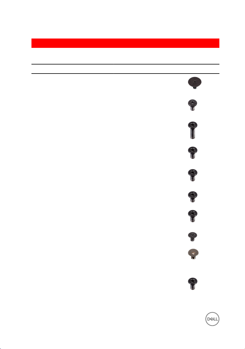
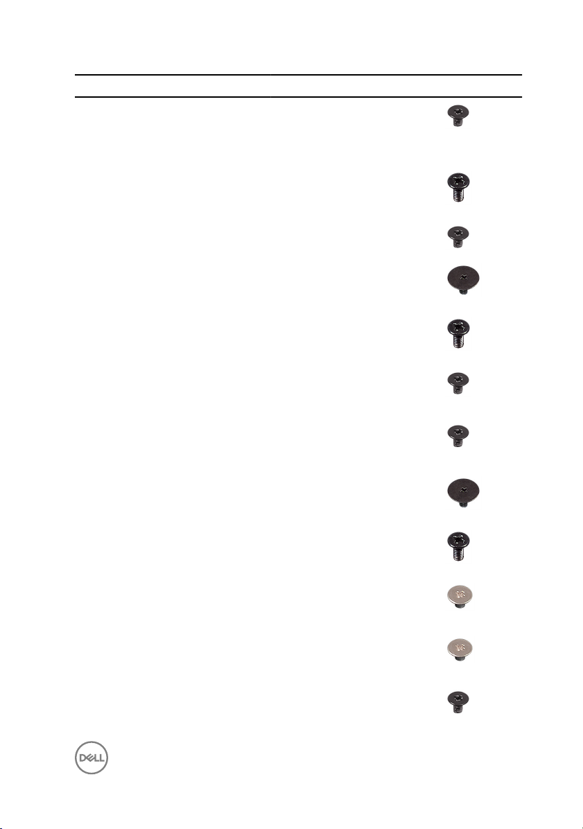
Screw list
Component Secured to Screw type Quantity Screw image
Base cover Palm rest and
keyboard
assembly
Base cover Palm rest and
keyboard
assembly
Base cover Palm rest and
keyboard
assembly
M2x2 Big Head 3
M2x4 2
M2.5x8 13
Battery Palm rest and
keyboard
assembly
Fan Palm rest and
keyboard
assembly
Hard drive Hard-drive
bracket
Hard-drive
bracket
Heat-sink
assembly
Hinge brackets Display back-
Hinge brackets Palm rest and
Palm rest and
keyboard
assembly
System board M2x3 3
cover and
antenna
assembly
keyboard
assembly
M2.5x5 1
M2.5x5 1
M3x3 4
M2.5x5 3
M2.5x3 6
M2.5x5 4
12
Component Secured to Screw type Quantity Screw image
Hinge (LCD
side)
I/O board Palm rest and
Optical-drive
bracket
Display backcover and
antenna
assembly
keyboard
assembly
Optical drive M2x3 2
M2x3 2
M2.5x5 1
Optical-drive
interposer
Palm rest and
keyboard
assembly bridge
Panel Palm rest and
Power-adapter
port
Power-button
board
System board Palm rest and
Touch pad Palm rest and
Touch-pad
bracket
Wireless-card
bracket
Palm rest and
keyboard
assembly
Palm rest and
keyboard
assembly
keyboard
assembly
Palm rest and
keyboard
assembly
Palm rest and
keyboard
assembly
keyboard
assembly
keyboard
assembly
Palm rest and
keyboard
assembly
System board M2x3 1
M2x2 Big Head 2
M2.5x5 2
M2x3 4
M2x3 1
M2x2 Big Head 1
M2.5x5 1
M2x2 4
M2x2 3
13

GUID-06588814-2678-4667-9FF9-C009F4BCE185
After working inside your computer
CAUTION: Leaving stray or loose screws inside your computer may severely
damage your computer.
1 Replace all screws and ensure that no stray screws remain inside your computer.
2 Connect any external devices, peripherals, or cables you removed before working
on your computer.
3 Replace any media cards, discs, or any other parts that you removed before
working on your computer.
4 Connect your computer and all attached devices to their electrical outlets.
5 Turn on your computer.
14

GUID-5F25DB7E-BE9A-49D8-A32A-AAD2A7EDBB9E
Removing the optical drive
WARNING: Before working inside your computer, read the safety
information that shipped with your computer and follow the steps in Before
working inside your computer. After working inside your computer, follow
the instructions in After working inside your computer. For more safety best
practices, see the Regulatory Compliance home page at
regulatory_compliance.
GUID-E85ABD07-B26F-44FC-9731-31D871BC4275
Procedure
1 Remove the screw that secures the optical-drive assembly to the base cover.
2 Using a plastic scribe, push the optical drive through the screw hole to release
the optical-drive assembly.
www.dell.com/
15
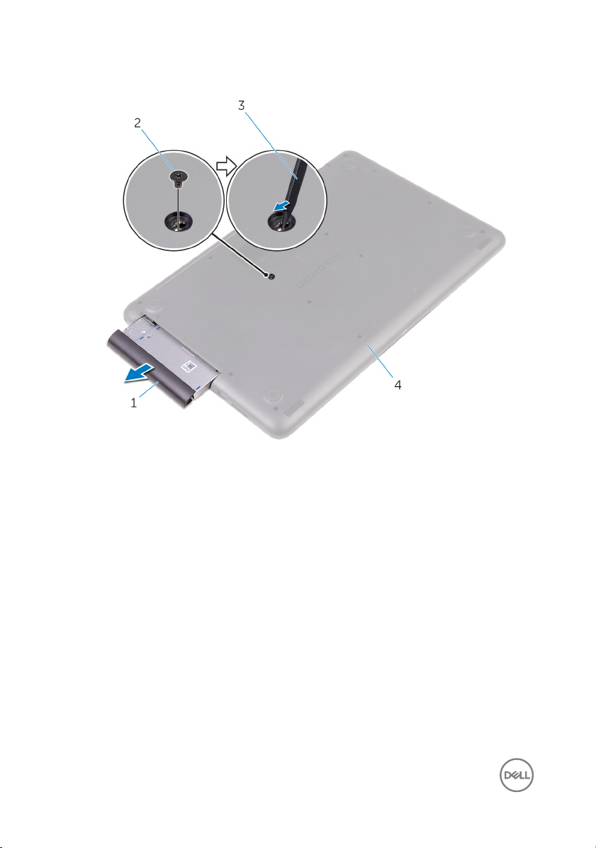
3 Slide the optical-drive assembly out of the optical-drive bay.
1 optical-drive assembly 2 M2x4 screw
3 plastic scribe 4 base cover
4 Remove the screws that secure the optical-drive bracket to the optical drive.
16
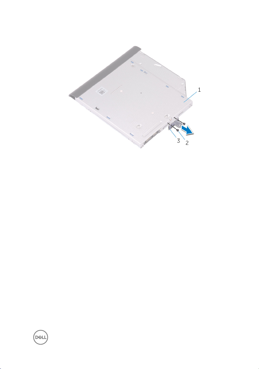
5 Remove the optical-drive bracket.
1 optical drive 2 M2x3 screws (2)
3 optical-drive bracket
17
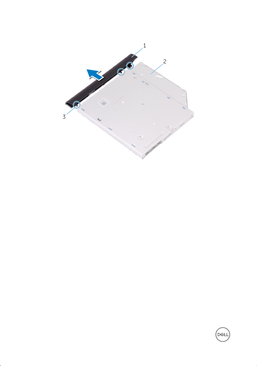
6 Pull the optical-drive bezel carefully to remove it from the optical drive.
1 optical-drive bezel 2 optical drive
3 tabs (3)
18
GUID-01750DAC-3408-4912-B936-7DAA79351AA9
Replacing the optical drive
WARNING: Before working inside your computer, read the safety
information that shipped with your computer and follow the steps in Before
working inside your computer. After working inside your computer, follow
the instructions in After working inside your computer. For more safety best
practices, see the Regulatory Compliance home page at
regulatory_compliance.
GUID-125B7F87-493C-4737-9187-834AC9519129
Procedure
1 Align the tabs on the optical-drive bezel with the slots on the optical drive and
snap the optical-drive bezel into place.
2 Align the screw holes on the optical-drive bracket with the screw holes on the
optical drive.
3 Replace the screws that secure the optical-drive bracket to the optical drive.
4 Slide the optical-drive assembly into the optical-drive bay.
5 Align the screw hole on the optical-drive bracket with the screw hole on the base
cover.
6 Replace the screw that secures the optical-drive assembly to the base cover.
www.dell.com/
19
GUID-98068FC2-1C1C-46DE-B3FA-DF9D488E9BA1
Removing the base cover
WARNING: Before working inside your computer, read the safety
information that shipped with your computer and follow the steps in Before
working inside your computer. After working inside your computer, follow
the instructions in After working inside your computer. For more safety best
practices, see the Regulatory Compliance home page at
regulatory_compliance.
GUID-23D2D516-90B7-4163-A50C-B2E52E691490
Prerequisites
Remove the optical drive.
www.dell.com/
20
GUID-B9630B7D-C146-43A6-89CA-DE271F30C997
Procedure
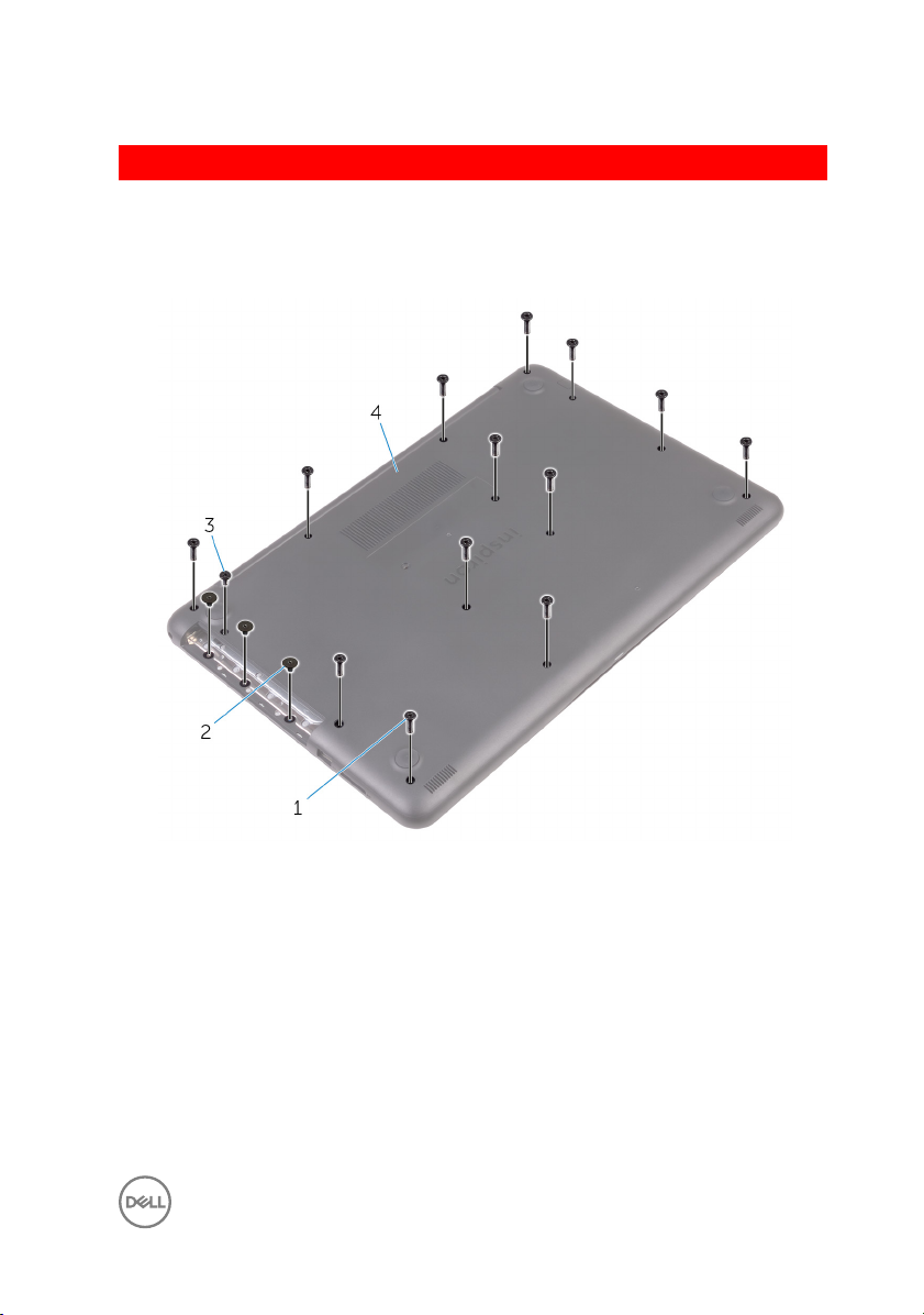
1 Remove the screws that secure the base cover to the palm rest and keyboard
assembly.
1 M2.5x8 screws (13) 2 M2x2 screws (3)
3 M2x4 screw 4 base cover
2 Using a plastic scribe, pry the base cover starting from the top-left corner of the
computer base.
21
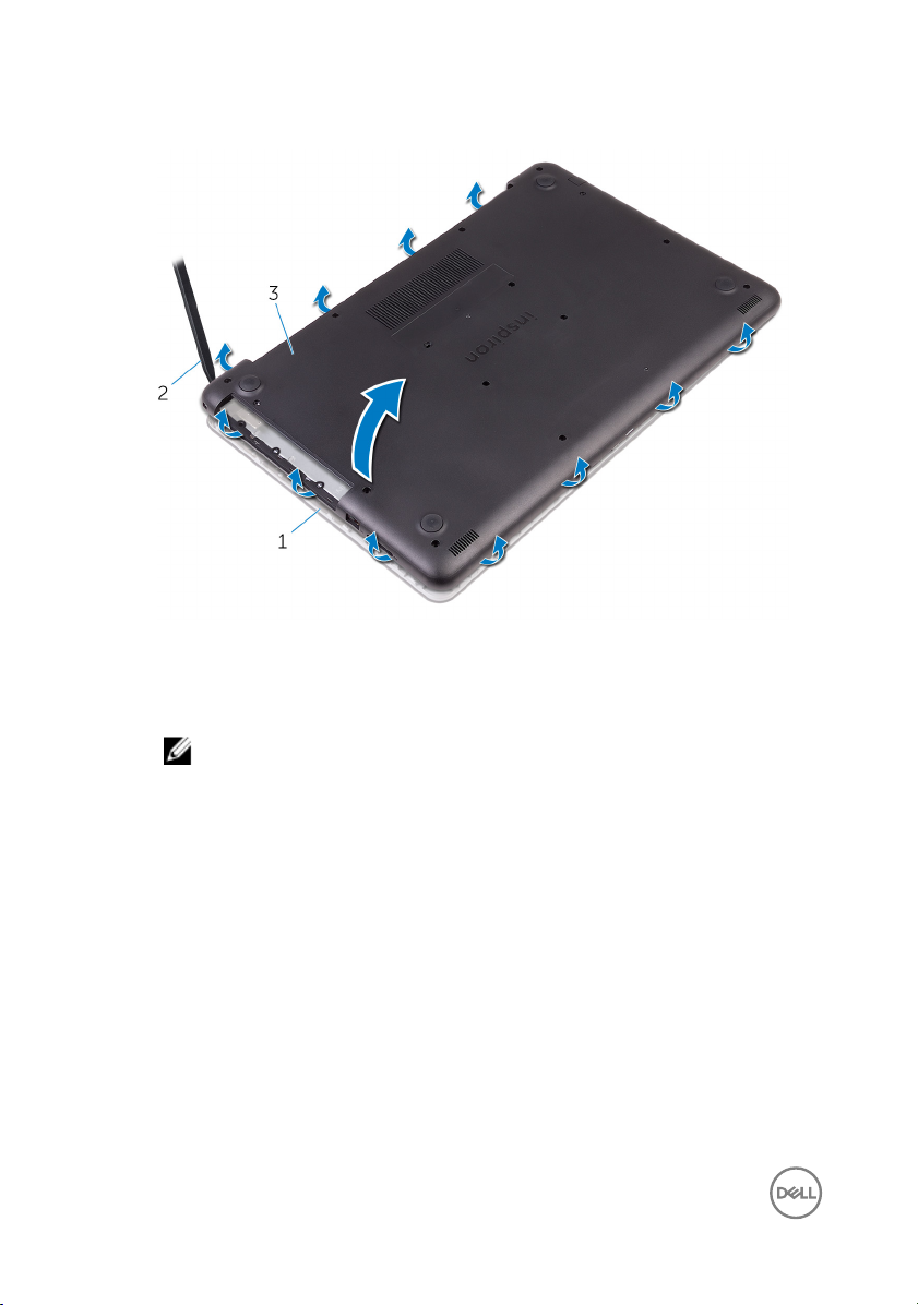
3 Lift the base cover o the palm rest and keyboard assembly at an angle.
22
1 palm rest and keyboard
assembly
3 base cover
NOTE: Follow step 4 and 5 only if you want to further remove any
component from the computer.
2 plastic scribe
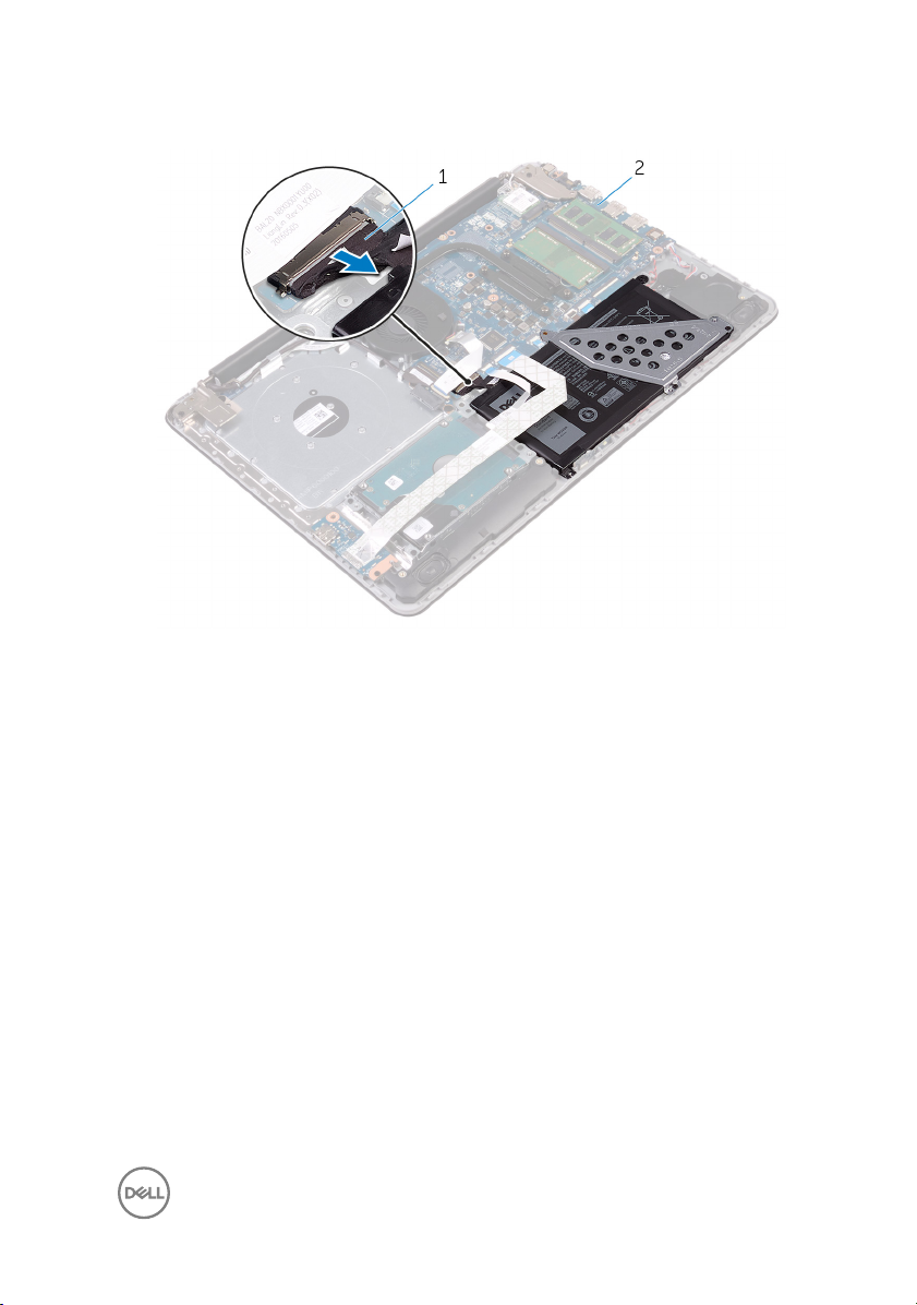
4 Disconnect the battery cable from the system board.
1 battery cable 2 system board
5 Press and hold the power button for 5 seconds to ground the system board.
23
GUID-27446428-82D7-4881-9220-9EB090B046EA
Replacing the base cover
WARNING: Before working inside your computer, read the safety
information that shipped with your computer and follow the steps in Before
working inside your computer. After working inside your computer, follow
the instructions in After working inside your computer. For more safety best
practices, see the Regulatory Compliance home page at
regulatory_compliance.
GUID-36436E52-BF74-4CD7-A51E-30CADC145758
Procedure
1 Connect the battery cable to the system board, if applicable.
CAUTION: To avoid accidental damage to the power-adapter port, do
not press the base cover against the power-adapter port when you
snap the base cover to the computer base.
www.dell.com/
24
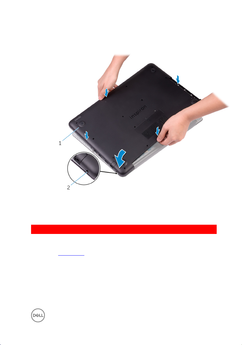
2 Place the base cover on the palm rest and keyboard assembly, and snap the base
cover into place starting from the power-adapter port.
1 base cover 2 power-adapter port
3 Replace the screws that secure the base cover to the palm rest and keyboard
assembly.
GUID-65FDA1CD-4E26-4BA7-B1DF-FD73E839CF5A
Post-requisites
Replace the optical drive.
25
GUID-AAC0DC5A-1680-492D-804F-52F812D409C2
Removing the memory modules
WARNING: Before working inside your computer, read the safety
information that shipped with your computer and follow the steps in Before
working inside your computer. After working inside your computer, follow
the instructions in After working inside your computer. For more safety best
practices, see the Regulatory Compliance home page at
regulatory_compliance.
GUID-B63E7AE3-1A63-42B8-8121-1A48547C357D
Prerequisites
1 Remove the optical drive.
2 Remove the base cover.
GUID-9031EF58-9B11-46DE-BC16-72882DFDDE0A
Procedure
1 Use your ngertips to carefully spread apart the securing-clips on each end of
the memory-module slot until the memory module pops up.
www.dell.com/
26
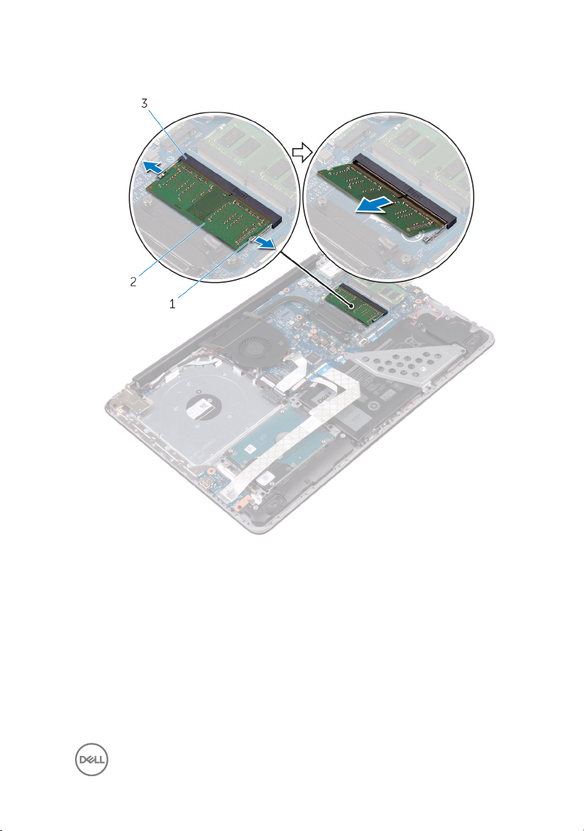
2 Remove the memory module from the memory-module slot.
1 securing clips (2) 2 memory module
3 memory-module slot
27
GUID-1F5023F5-9868-4AAF-A9F5-BFB400CD890A
Replacing the memory modules
WARNING: Before working inside your computer, read the safety
information that shipped with your computer and follow the steps in Before
working inside your computer. After working inside your computer, follow
the instructions in After working inside your computer. For more safety best
practices, see the Regulatory Compliance home page at
regulatory_compliance.
GUID-CAB8F52D-7F5B-4847-B34A-91B741249DF9
Procedure
1 Align the notch on the memory module with the tab on the memory-module slot.
www.dell.com/
28

2 Slide the memory module rmly into the slot at an angle and press the memory
module down until it clicks into place.
NOTE: If you do not hear the click, remove the memory module and
reinstall it.
1 notch 2 tab
3 memory-module slot 4 memory module
3 Connect the battery cable to the system board.
29

GUID-FC885216-4D9B-490B-8E29-934447E8E5D4
Post-requisites
1 Replace the base cover.
2 Replace the optical drive.
30
 Loading...