

Page 1

Inspiron 15-3573
Service Manual
Computer Model: Inspiron 15-3573
Regulatory Model: P63F
Regulatory Type: P63F004
Page 2

Notes, cautions, and warnings
NOTE: A NOTE indicates important information that helps you make
better use of your product.
CAUTION: A CAUTION indicates either potential damage to hardware or
loss of data and tells you how to avoid the problem.
WARNING: A WARNING indicates a potential for property damage,
personal injury, or death.
© 2018 Dell Inc. or its subsidiaries. All rights reserved. Dell, EMC, and other trademarks
are trademarks of Dell Inc. or its subsidiaries. Other trademarks may be trademarks of their
respective owners.
2018 - 01
Rev. A00
Page 3

Contents
Before working inside your computer........................... 11
Before you begin .....................................................................................11
Safety instructions...................................................................................11
Recommended tools............................................................................... 12
Screw list................................................................................................ 13
After working inside your computer............................. 15
Removing the battery.................................................. 16
Procedure............................................................................................... 16
Replacing the battery.................................................. 18
Procedure............................................................................................... 18
Removing the optical drive.......................................... 19
Prerequisites........................................................................................... 19
Procedure............................................................................................... 19
Replacing the optical drive.......................................... 22
Procedure...............................................................................................22
Post-requisites....................................................................................... 22
Removing the keyboard...............................................23
Prerequisites...........................................................................................23
Procedure...............................................................................................23
3
Page 4

Replacing the keyboard............................................... 26
Procedure...............................................................................................26
Post-requisites....................................................................................... 26
Removing the base cover............................................ 27
Prerequisites...........................................................................................27
Procedure...............................................................................................27
Replacing the base cover............................................ 32
Procedure...............................................................................................32
Post-requisites....................................................................................... 34
Removing the optical-drive interposer.........................35
Prerequisites...........................................................................................35
Procedure...............................................................................................35
Replacing the optical-drive interposer......................... 37
Procedure...............................................................................................37
Post-requisites........................................................................................37
Removing the hard drive............................................. 38
Prerequisites...........................................................................................38
Procedure...............................................................................................38
Replacing the hard drive.............................................. 41
Procedure............................................................................................... 41
Post-requisites........................................................................................ 41
Removing the memory modules.................................. 42
Prerequisites...........................................................................................42
Procedure...............................................................................................42
4
Page 5

Replacing the memory modules...................................44
Procedure...............................................................................................44
Post-requisites....................................................................................... 45
Removing the wireless card.........................................46
Prerequisites...........................................................................................46
Procedure...............................................................................................46
Replacing the wireless card......................................... 48
Procedure...............................................................................................48
Post-requisites....................................................................................... 49
Removing the power-button board.............................. 51
Prerequisites........................................................................................... 51
Procedure............................................................................................... 51
Replacing the power-button board..............................54
Procedure...............................................................................................54
Post-requisites....................................................................................... 54
Removing the speakers...............................................56
Prerequisites.......................................................................................... 56
Procedure.............................................................................................. 56
Replacing the speakers............................................... 58
Procedure.............................................................................................. 58
Post-requisites....................................................................................... 58
Removing the I/O board..............................................59
Prerequisites.......................................................................................... 59
Procedure.............................................................................................. 59
5
Page 6

Replacing the I/O board...............................................61
Procedure............................................................................................... 61
Post-requisites........................................................................................ 61
Removing the coin-cell battery................................... 62
Prerequisites...........................................................................................62
Procedure...............................................................................................62
Replacing the coin-cell battery....................................64
Procedure...............................................................................................64
Post-requisites....................................................................................... 64
Removing the heat sink...............................................65
Prerequisites.......................................................................................... 65
Procedure.............................................................................................. 65
Replacing the heat sink............................................... 67
Procedure...............................................................................................67
Post-requisites........................................................................................67
Removing the fan........................................................68
Prerequisites...........................................................................................68
Procedure...............................................................................................68
Replacing the fan........................................................ 70
Procedure...............................................................................................70
Post-requisites........................................................................................70
Removing the status-light lens.....................................71
Prerequisites........................................................................................... 71
Procedure............................................................................................... 71
6
Page 7

Replacing the status-light lens.................................... 73
Post-requisites........................................................................................73
Procedure...............................................................................................73
Removing the system board........................................ 74
Prerequisites........................................................................................... 74
Procedure...............................................................................................75
Replacing the system board........................................ 79
Procedure...............................................................................................79
Post-requisites....................................................................................... 80
Removing the touchpad...............................................81
Prerequisites........................................................................................... 81
Procedure............................................................................................... 81
Replacing the touchpad...............................................84
Procedure...............................................................................................84
Post-requisites....................................................................................... 84
Removing the power-adapter port.............................. 85
Prerequisites.......................................................................................... 85
Procedure.............................................................................................. 85
Replacing the power-adapter port...............................87
Procedure...............................................................................................87
Post-requisites........................................................................................87
Removing the display assembly...................................88
Prerequisites...........................................................................................88
Procedure...............................................................................................88
7
Page 8

Replacing the display assembly................................... 92
Procedure...............................................................................................92
Post-requisites....................................................................................... 92
Removing the display bezel......................................... 93
Prerequisites...........................................................................................93
Procedure...............................................................................................94
Replacing the display bezel......................................... 95
Procedure.............................................................................................. 95
Post-requisites....................................................................................... 95
Removing the display panel.........................................96
Prerequisites.......................................................................................... 96
Procedure.............................................................................................. 96
Replacing the display panel......................................... 99
Post-requisites....................................................................................... 99
Procedure.............................................................................................. 99
Removing the camera................................................100
Prerequisites.........................................................................................100
Procedure.............................................................................................100
Replacing the camera................................................ 102
Procedure.............................................................................................102
Post-requisites......................................................................................102
Removing the display hinges......................................103
Prerequisites......................................................................................... 103
Procedure.............................................................................................103
8
Page 9

Replacing the display hinges......................................105
Post-requisites......................................................................................105
Procedure.............................................................................................105
Removing the display back-cover and antenna
assembly....................................................................106
Prerequisites......................................................................................... 106
Procedure.............................................................................................106
Replacing the display back-cover and antenna
assembly....................................................................108
Procedure.............................................................................................108
Post-requisites......................................................................................108
Removing the palm rest.............................................109
Prerequisites......................................................................................... 109
Procedure.............................................................................................109
Replacing the palm rest...............................................111
Post-requisites....................................................................................... 111
Procedure...............................................................................................111
Downloading drivers................................................... 112
Downloading the audio driver................................................................ 112
Downloading the graphics driver............................................................112
Downloading the USB 3.0 driver............................................................ 113
Downloading the Wi-Fi driver.................................................................113
Downloading the media-card reader driver............................................ 113
Downloading the chipset driver............................................................. 114
9
Page 10

System setup............................................................. 115
Boot Sequence......................................................................................115
Navigation keys..................................................................................... 115
BIOS overview.......................................................................................116
Entering BIOS setup program................................................................ 116
System setup options............................................................................ 117
Troubleshooting......................................................... 123
Flashing the BIOS................................................................................. 123
Flashing BIOS (USB key)...................................................................... 123
Enhanced Pre-Boot System Assessment (ePSA) diagnostics............... 124
Running the ePSA diagnostics........................................................ 124
Diagnostics........................................................................................... 125
Flea power release................................................................................126
Wi-Fi power cycle................................................................................. 127
Getting help and contacting Dell................................128
Self-help resources............................................................................... 128
Contacting Dell..................................................................................... 129
10
Page 11
Before working inside your computer
NOTE: The images in this document may dier from your computer
depending on the conguration you ordered.
Before you begin
1 Save and close all open les and exit all open applications.
2 Shut down your computer. Click Start → Power → Shut down.
NOTE: If you are using a dierent operating system, see the
documentation of your operating system for shut-down instructions.
3 Disconnect your computer and all attached devices from their electrical outlets.
4 Disconnect all attached network devices and peripherals, such as keyboard,
mouse, and monitor from your computer.
5 Remove any media card and optical disc from your computer, if applicable.
Safety instructions
Use the following safety guidelines to protect your computer from potential damage
and ensure your personal safety.
WARNING: Before working inside your computer, read the safety
information that shipped with your computer. For more safety best
practices, see the Regulatory Compliance home page at www.dell.com/
regulatory_compliance.
WARNING: Disconnect all power sources before opening the computer
cover or panels. After you nish working inside the computer, replace all
covers, panels, and screws before connecting to the electrical outlet.
CAUTION: To avoid damaging the computer, ensure that the work surface is
at and clean.
11
Page 12

CAUTION: To avoid damaging the components and cards, handle them by
their edges, and avoid touching pins and contacts.
CAUTION: You should only perform troubleshooting and repairs as
authorized or directed by the Dell technical assistance team. Damage due
to servicing that is not authorized by Dell is not covered by your warranty.
See the safety instructions that shipped with the product or at
www.dell.com/regulatory_compliance.
CAUTION: Before touching anything inside your computer, ground yourself
by touching an unpainted metal surface, such as the metal at the back of
the computer. While you work, periodically touch an unpainted metal
surface to dissipate static electricity, which could harm internal
components.
CAUTION: When you disconnect a cable, pull on its connector or on its pull
tab, not on the cable itself. Some cables have connectors with locking tabs
or thumb-screws that you must disengage before disconnecting the cable.
When disconnecting cables, keep them evenly aligned to avoid bending any
connector pins. When connecting cables, ensure that the ports and
connectors are correctly oriented and aligned.
CAUTION: Press and eject any installed card from the media-card reader.
Recommended tools
The procedures in this document may require the following tools:
• Phillips screwdriver #1
• Plastic scribe
12
Page 13

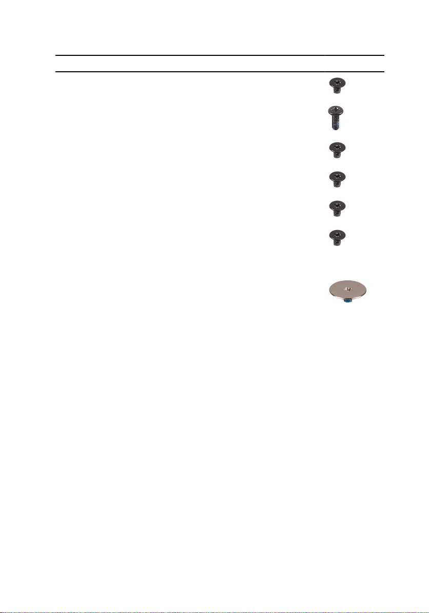
Screw list
The following table provides the list of screws that are used for securing dierent
components to the palm-rest assembly.
Table 1. Screw list
Component Secured to Screw type Quantity Screw image
Optical-drive
assembly
Base cover M2x5 1
Optical-drive
bracket
Base cover Palm-rest
Base cover Palm-rest
Base cover Palm-rest
Base cover Palm-rest
Hard-drive
assembly
Hard-drive
bracket
Wireless-card
bracket
Display hinge Palm-rest
Optical drive M2x3 1
assembly
assembly
assembly
assembly
Palm-rest
assembly
Hard drive M3x3 4
System board M2x3 1
assembly
M2.5x8 8
M2x5 2
M2x2 3
M2x5 5
M2x3 4
M2.5x8 3
Power-button
board
Palm-rest
assembly
M2x2 1
13
Page 14
Component Secured to Screw type Quantity Screw image
I/O board Palm-rest
assembly
Fan System board M2x5 2
M2x3 1
System board Palm-rest
assembly
Touch-pad
bracket
Power-adapter
port
Display panel Display back-
Display hinges Display back-
Touch pad M2x3 6
Palm-rest
assembly
cover and
antenna
assembly
cover and
antenna
assembly
M2x3 2
M2x3 1
M2x3 4
M2.5xM2.5 big
head
6
14
Page 15

After working inside your computer
CAUTION: Leaving stray or loose screws inside your computer may severely
damage your computer.
1 Replace all screws and ensure that no stray screws remain inside your computer.
2 Connect any external devices, peripherals, or cables you removed before
working on your computer.
3 Replace any media cards, discs, or any other parts that you removed before
working on your computer.
4 Connect your computer and all attached devices to their electrical outlets.
5 Turn on your computer.
15
Page 16
Removing the battery
WARNING: Before working inside your computer, read the safety
information that shipped with your computer and follow the steps in Before
working inside your computer. After working inside your computer, follow
the instructions in After working inside your computer. For more safety best
practices, see the Regulatory Compliance home page at
regulatory_compliance.
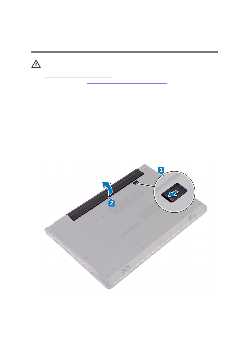
Procedure
1 Slide the battery-release latch to the unlocked position.
You hear a click sound when the battery is unlocked.
2 Using your ngertips, lift the battery at an angle and remove it from the battery
bay.
www.dell.com/
16
Page 17

3 Turn the computer over, open the display, and press the power button for ve
seconds to ground the system board.
17
Page 18

Replacing the battery
WARNING: Before working inside your computer, read the safety
information that shipped with your computer and follow the steps in Before
working inside your computer. After working inside your computer, follow
the instructions in After working inside your computer. For more safety best
practices, see the Regulatory Compliance home page at
regulatory_compliance.
Procedure
1 Close the display and turn the computer over.
2 Place the battery in the battery bay and snap the battery into place.
www.dell.com/
18
Page 19

Removing the optical drive
WARNING: Before working inside your computer, read the safety
information that shipped with your computer and follow the steps in Before
working inside your computer. After working inside your computer, follow
the instructions in After working inside your computer. For more safety best
practices, see the Regulatory Compliance home page at
regulatory_compliance.
Prerequisites
Remove the battery.
Procedure
1 Remove the screw (M2x5) that secures the optical-drive assembly to the base
cover.
2 Using a plastic scribe, push to release the optical-drive assembly from the
optical-drive bay.
www.dell.com/
19
Page 20
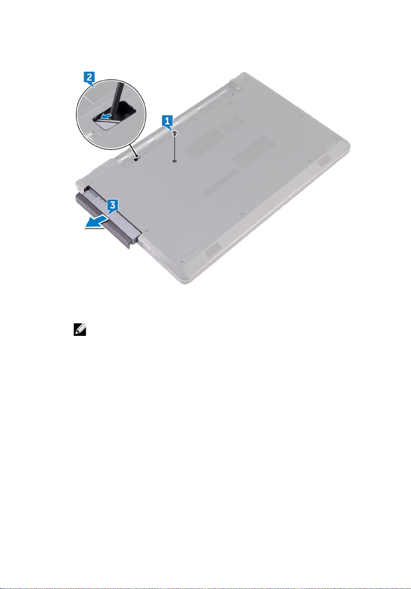
3 Pull the optical-drive assembly out of the optical-drive bay.
4 Remove the screw (M2x3) that secures the optical-drive bracket to the optical
drive.
NOTE: Note the orientation of the optical-drive bracket so that you
can replace it correctly.
20
Page 21
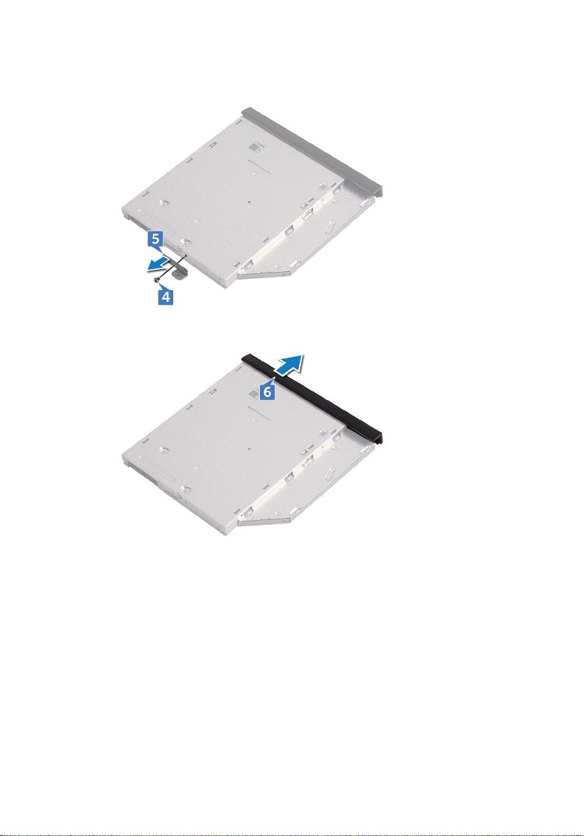
5 Remove the optical-drive bracket from the optical drive.
6 Carefully pull the optical-drive bezel and remove it from the optical drive.
21
Page 22

Replacing the optical drive
WARNING: Before working inside your computer, read the safety
information that shipped with your computer and follow the steps in Before
working inside your computer. After working inside your computer, follow
the instructions in After working inside your computer. For more safety best
practices, see the Regulatory Compliance home page at
regulatory_compliance.
Procedure
1 Align the tabs on the optical-drive bezel with the slots on the optical drive and
snap it into place.
2 Align the screw hole on the optical-drive bracket with the screw hole on the
optical-drive assembly.
NOTE: You must correctly align the optical-drive bracket to ensure that
the optical drive can be properly secured to the computer. For correct
orientation, see step 4 in "Removing the optical drive".
3 Replace the screw (M2x3) that secures the optical-drive bracket to the optical-
drive assembly.
4 Slide the optical-drive assembly into the optical-drive bay and snap it into place.
5 Replace the screw (M2x5) that secures the optical-drive assembly to the
computer base.
www.dell.com/
Post-requisites
Replace the battery.
22
Page 23

Removing the keyboard
WARNING: Before working inside your computer, read the safety
information that shipped with your computer and follow the steps in Before
working inside your computer. After working inside your computer, follow
the instructions in After working inside your computer. For more safety best
practices, see the Regulatory Compliance home page at
regulatory_compliance.
Prerequisites
Remove the battery.
Procedure
1 Turn the computer over and open the display as far as possible.
2 Using a plastic scribe, gently release the tabs that secure the keyboard to the
palm-rest assembly.
3 Slide the keyboard up to release it from the slots on the palm-rest assembly.
www.dell.com/
23
Page 24
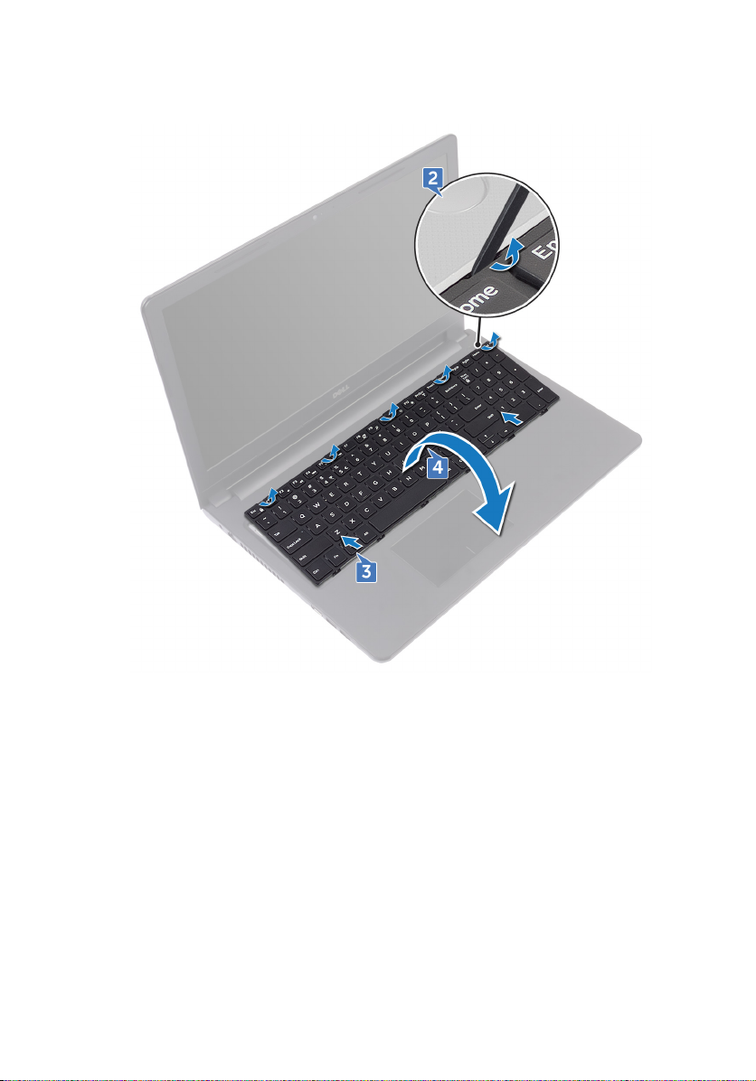
4 Carefully turn the keyboard over and place it on the palm-rest assembly.
5 Open the latch and disconnect the keyboard cable from the system board.
24
Page 25
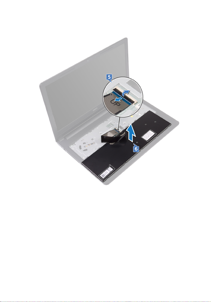
6 Lift the keyboard o the palm-rest assembly.
25
Page 26

Replacing the keyboard
WARNING: Before working inside your computer, read the safety
information that shipped with your computer and follow the steps in Before
working inside your computer. After working inside your computer, follow
the instructions in After working inside your computer. For more safety best
practices, see the Regulatory Compliance home page at
regulatory_compliance.
Procedure
1 Slide the keyboard cable into the system-board connector and close the latch to
secure the cable.
2 Turn the keyboard over, slide the tabs on the keyboard into the slots on the
palm-rest assembly, and snap the keyboard into place.
Post-requisites
Replace the battery.
www.dell.com/
26
Page 27

Removing the base cover
WARNING: Before working inside your computer, read the safety
information that shipped with your computer and follow the steps in Before
working inside your computer. After working inside your computer, follow
the instructions in After working inside your computer. For more safety best
practices, see the Regulatory Compliance home page at
regulatory_compliance.
Prerequisites
1 Remove the battery.
2 Follow the procedure from step 1 to step 3 in “Removing the optical drive”.
3 Remove the keyboard.
Procedure
1 Remove the ve screws (M2x5) that secure the base cover to the palm-rest
assembly.
www.dell.com/
27
Page 28
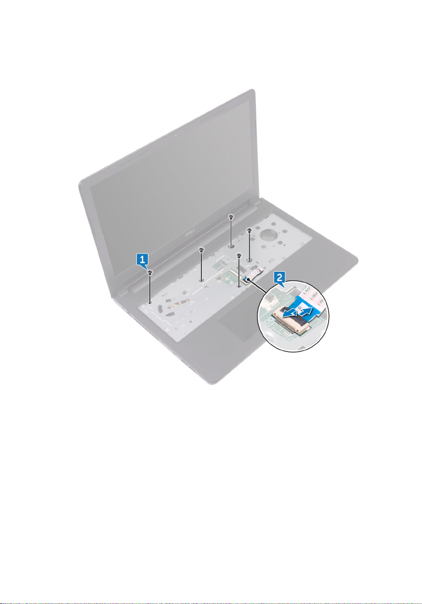
2 Open the latch, and disconnect the optical-drive cable from the connector on
the system board.
3 Close the display and the turn the computer over.
4 Remove the eight screws (M2.5x8) that secure the base cover to the palm-rest
assembly.
5 Remove the three screws (M2x2) that secure the base cover to the palm-rest
assembly.
28
Page 29
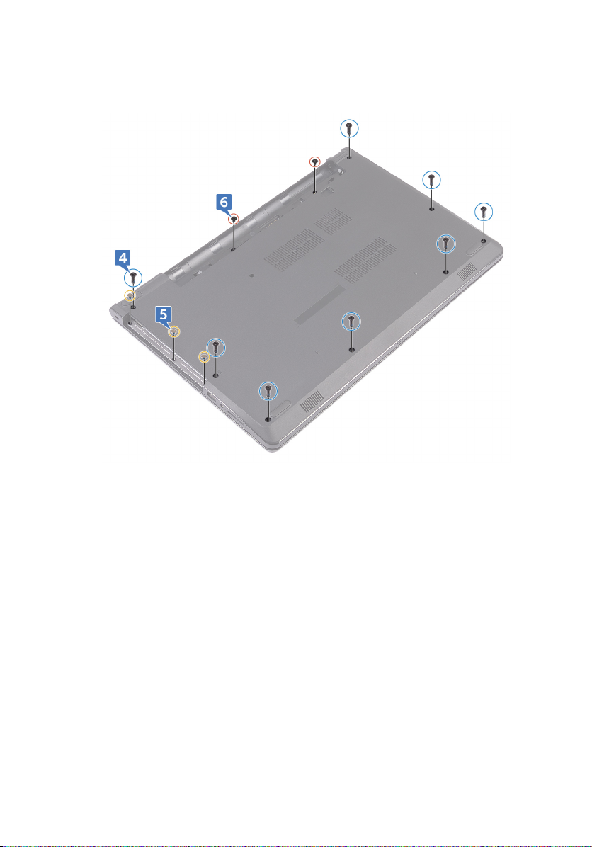
6 Remove the two screws (M2x5) that secure the base cover to the palm-rest
assembly.
29
Page 30
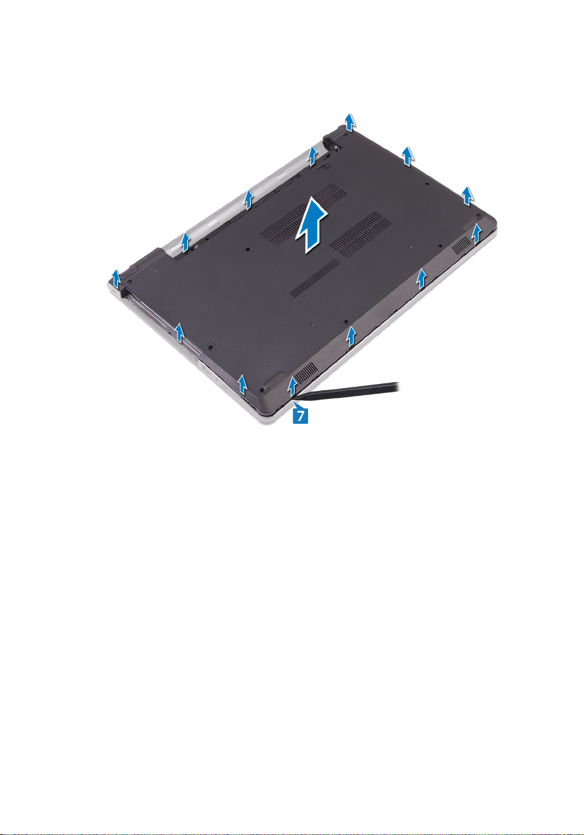
7 Using a plastic scribe, pry the base cover o the palm-rest assembly.
8 Turn the base cover over.
30
Page 31

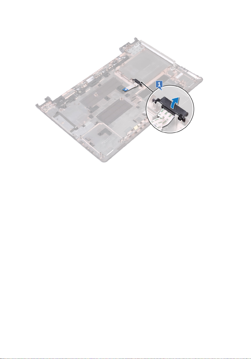
9 Remove the optical-drive interposer.
31
Page 32

Replacing the base cover
WARNING: Before working inside your computer, read the safety
information that shipped with your computer and follow the steps in Before
working inside your computer. After working inside your computer, follow
the instructions in After working inside your computer. For more safety best
practices, see the Regulatory Compliance home page at
regulatory_compliance.
Procedure
1 Replace the optical-drive interposer.
2 Turn the base cover over.
www.dell.com/
32
Page 33

3 Place the base cover on the palm-rest assembly and route the optical-drive
cable through the slot on the palm-rest assembly.
4 Slide the tabs on the base cover into the slots on the palm-rest assembly and
snap the base cover into place.
5 Slide the optical-drive cable into its connector on the system board and close
the latch to secure the cable.
6 Replace the ve screws (M2x5) that secure the palm-rest assembly to the base
cover.
7 Close the display and turn the computer over.
8 Replace the three screws (M2x2) that secure the base cover to the palm-rest
assembly.
33
Page 34

9 Replace the two screws (M2x5) that secure the base cover to the palm-rest
assembly.
10 Replace the eight screws (M2.5x8) that secure the base cover to the palm-rest
assembly.
Post-requisites
1 Replace the keyboard.
2 Follow the procedure from step 4 to step 5 in “Replacing the optical drive”.
3 Replace the battery.
34
Page 35

Removing the optical-drive interposer
WARNING: Before working inside your computer, read the safety
information that shipped with your computer and follow the steps in Before
working inside your computer. After working inside your computer, follow
the instructions in After working inside your computer. For more safety best
practices, see the Regulatory Compliance home page at
regulatory_compliance.
Prerequisites
1 Remove the battery.
2 Follow the procedure from step 1 to step 3 in “Removing the optical drive”.
3 Remove the keyboard.
4 Follow the procedure from step 1 to step 8 in “Removing the base cover”.
Procedure
Release the optical-drive interposer from the tabs on the base cover.
www.dell.com/
35
Page 36
36
Page 37

Replacing the optical-drive interposer
WARNING: Before working inside your computer, read the safety
information that shipped with your computer and follow the steps in Before
working inside your computer. After working inside your computer, follow
the instructions in After working inside your computer. For more safety best
practices, see the Regulatory Compliance home page at
regulatory_compliance.
Procedure
Align the tabs on the base cover and snap it into place.
Post-requisites
1 Follow the procedure from step 2 to step 9 in “Replacing the base cover”.
2 Replace the keyboard.
3 Follow the procedure from step 4 to step 5 in “Replacing the optical drive”.
4 Replace the battery.
www.dell.com/
37
Page 38

Removing the hard drive
WARNING: Before working inside your computer, read the safety
information that shipped with your computer and follow the steps in Before
working inside your computer. After working inside your computer, follow
the instructions in After working inside your computer. For more safety best
practices, see the Regulatory Compliance home page at
regulatory_compliance.
CAUTION: Hard drives are fragile. Exercise care when handling the hard
drive.
CAUTION: To avoid data loss, do not remove the hard drive while the
computer is in sleep or on state.
Prerequisites
1 Remove the battery.
2 Follow the procedure from step 1 to step 3 in “Removing the optical drive”.
3 Remove the keyboard.
4 Follow the procedure from step 1 to step 7 in “Removing the base cover”.
Procedure
www.dell.com/
1 Open the latch and disconnect the hard-drive cable from the system board.
2 Remove the four screws (M2x3) that secure the hard-drive assembly to the
palm-rest assembly.
38
Page 39

3 Lift the hard-drive assembly o the palm-rest assembly.
4 Disconnect the interposer from the hard-drive assembly.
5 Remove the four screws (M3x3) that secure the hard-drive bracket to the hard
drive.
39
Page 40

6 Lift the hard drive o the hard-drive bracket.
40
Page 41

Replacing the hard drive
WARNING: Before working inside your computer, read the safety
information that shipped with your computer and follow the steps in Before
working inside your computer. After working inside your computer, follow
the instructions in After working inside your computer. For more safety best
practices, see the Regulatory Compliance home page at
regulatory_compliance.
CAUTION: Hard drives are fragile. Exercise care when handling the hard
drive.
Procedure
1 Align the screw holes on the hard-drive bracket with the screw holes on the
hard drive.
2 Replace the four screws (M3x3) that secure the hard-drive bracket to the hard
drive.
3 Connect the interposer to the hard drive.
4 Place the hard-drive assembly in the palm-rest assembly and align the screw
holes on the hard-drive assembly with the screw holes on the palm-rest
assembly.
5 Replace the four screws (M2x3) that secure the hard-drive assembly to the
palm-rest assembly.
6 Slide the hard-drive cable into its connector on the system board and close the
latch to secure the cable.
www.dell.com/
Post-requisites
1 Follow the procedure from step 2 to step 8 in “Replacing the base cover”.
2 Replace the keyboard.
3 Follow the procedure from step 4 to step 5 in “Replacing the optical drive”.
4 Replace the battery.
41
Page 42

Removing the memory modules
WARNING: Before working inside your computer, read the safety
information that shipped with your computer and follow the steps in Before
working inside your computer. After working inside your computer, follow
the instructions in After working inside your computer. For more safety best
practices, see the Regulatory Compliance home page at
regulatory_compliance.
Prerequisites
1 Remove the battery.
2 Follow the procedure from step 1 to step 3 in “Removing the optical drive”.
3 Remove the keyboard.
4 Follow the procedure from step 1 to step 7 in “Removing the base cover”.
Procedure
1 Using your ngertips, carefully spread apart the securing clips on each end of
the memory-module slot until the memory module pops up.
www.dell.com/
42
Page 43

2 Slide and remove the memory module from the memory-module slot.
43
Page 44

Replacing the memory modules
WARNING: Before working inside your computer, read the safety
information that shipped with your computer and follow the steps in Before
working inside your computer. After working inside your computer, follow
the instructions in After working inside your computer. For more safety best
practices, see the Regulatory Compliance home page at
regulatory_compliance.
Procedure
1 Align the notch on the memory module with the tab on the memory-module slot
and slide it rmly into the slot at an angle.
www.dell.com/
44
Page 45

2 Press the memory module down until it clicks into place.
NOTE: If you do not hear the click, remove the memory module and
reinstall it.
Post-requisites
1 Follow the procedure from step 2 to step 8 in “Replacing the base cover”.
2 Replace the keyboard.
3 Follow the procedure from step 4 to step 5 in “Replacing the optical drive”.
4 Replace the battery.
45
Page 46

Removing the wireless card
WARNING: Before working inside your computer, read the safety
information that shipped with your computer and follow the steps in Before
working inside your computer. After working inside your computer, follow
the instructions in After working inside your computer. For more safety best
practices, see the Regulatory Compliance home page at
regulatory_compliance.
Prerequisites
1 Remove the battery.
2 Follow the procedure from step 1 to step 3 in “Removing the optical drive”.
3 Remove the keyboard.
4 Follow the procedure from step 1 to step 7 in “Removing the base cover”.
Procedure
1 Remove the screw (M2x3) that secures the wireless-card bracket to the
wireless card and system board.
2 Remove the wireless-card bracket from the wireless card.
3 Disconnect the antenna cables from the wireless card.
www.dell.com/
46
Page 47

4 Slide and remove the wireless card from the wireless-card slot.
47
Page 48

Replacing the wireless card
WARNING: Before working inside your computer, read the safety
information that shipped with your computer and follow the steps in Before
working inside your computer. After working inside your computer, follow
the instructions in After working inside your computer. For more safety best
practices, see the Regulatory Compliance home page at
regulatory_compliance.
Procedure
CAUTION: To avoid damage to the wireless card, do not place any cables
under it.
1 Align the notch on the wireless card with the tab on the wireless-card slot.
2 Slide the wireless card at an angle into the wireless-card slot.
www.dell.com/
48
Page 49

3 Connect the antenna cables to the wireless card.
The following table provides the antenna-cable color scheme for the wireless
card supported by your computer:
Table 2. Antenna-cable color scheme
Connectors on the wireless card Antenna cable color
Auxiliary (black triangle) Black
Main (white triangle) White
4 Align the screw hole on the wireless-card bracket with the screw hole on the
wireless card and the system board.
5 Replace the screw (M2x3) that secures the wireless-card bracket to the
wireless card and system board.
Post-requisites
1 Follow the procedure from step 2 to step 8 in “Replacing the base cover”.
2 Replace the keyboard.
49
Page 50

3 Follow the procedure from step 4 to step 5 in “Replacing the optical drive”.
4 Replace the battery.
50
Page 51

Removing the power-button board
WARNING: Before working inside your computer, read the safety
information that shipped with your computer and follow the steps in Before
working inside your computer. After working inside your computer, follow
the instructions in After working inside your computer. For more safety best
practices, see the Regulatory Compliance home page at
regulatory_compliance.
Prerequisites
1 Remove the battery.
2 Follow the procedure from step 1 to step 3 in “Removing the optical drive”.
3 Remove the keyboard.
4 Follow the procedure from step 1 to step 7 in “Removing the base cover”.
Procedure
1 Remove the two screws (M2.5x8) that secure the display hinge to the palm-rest
assembly.
www.dell.com/
51
Page 52

2 Open the hinge to an angle of 90 degrees.
3 Open the latch and disconnect the power-button board cable from the system
board.
4 Remove the screw (M2x2) that secures the power-button board to the palm-
rest assembly.
5 Peel the tape that secures the power-button board to the palm-rest assembly.
6 Slide and remove the power-button board from the tab on the palm-rest
assembly.
52
Page 53

7 Note the power-button board cable routing and peel it o the palm-rest
assembly.
53
Page 54

Replacing the power-button board
WARNING: Before working inside your computer, read the safety
information that shipped with your computer and follow the steps in Before
working inside your computer. After working inside your computer, follow
the instructions in After working inside your computer. For more safety best
practices, see the Regulatory Compliance home page at
regulatory_compliance.
Procedure
1 Slide the power-button board under the tab on the palm-rest assembly and align
the screw hole on the power-button board with the screw hole on the palm-rest
assembly.
2 Replace the screw (M2x2) that secures the power-button board to the palm-
rest assembly.
3 Adhere the tape that secures the power-button board to the palm-rest
assembly.
4 Route the power-button board cable through the slot on the palm-rest
assembly.
5 Slide the power-button board cable into its connector on the system board and
close the latch to secure the cable.
6 Close the display hinges.
7 Align the screw holes on the display hinges with the screw holes on the palm-
rest assembly.
8 Replace the two screws (M2.5x8) that secure the display hinges to the palm-
rest assembly.
www.dell.com/
Post-requisites
1 Follow the procedure from step 2 to step 8 in “Replacing the base cover”.
2 Replace the keyboard.
3 Follow the procedure from step 4 to step 5 in “Replacing the optical drive”.
54
Page 55

4 Replace the battery.
55
Page 56

Removing the speakers
WARNING: Before working inside your computer, read the safety
information that shipped with your computer and follow the steps in Before
working inside your computer. After working inside your computer, follow
the instructions in After working inside your computer. For more safety best
practices, see the Regulatory Compliance home page at
regulatory_compliance.
Prerequisites
1 Remove the battery.
2 Follow the procedure from step 1 to step 3 in “Removing the optical drive”.
3 Remove the keyboard.
4 Follow the procedure from step 1 to step 7 in “Removing the base cover”.
Procedure
1 Disconnect the speaker cable from the system board.
2 Peel o the tape that secures the speaker cable to the palm-rest assembly.
www.dell.com/
56
Page 57

3 Note the speaker-cable routing and lift the speakers, along with the speaker
cable, o the palm-rest assembly.
NOTE: Note the position of the rubber grommets before lifting the
speaker.
57
Page 58

Replacing the speakers
WARNING: Before working inside your computer, read the safety
information that shipped with your computer and follow the steps in Before
working inside your computer. After working inside your computer, follow
the instructions in After working inside your computer. For more safety best
practices, see the Regulatory Compliance home page at
regulatory_compliance.
Procedure
NOTE: The rubber grommets may get pushed out while replacing the
speaker. Ensure that the rubber grommets are in their position after placing
the speaker on the system board.
1 Align the speakers using the alignment posts on the palm-rest assembly and
snap the speakers into place.
2 Route the speaker cable through the routing guides on the palm-rest assembly.
3 Connect the speaker cable to the system board.
4 Adhere the tape that secures the speaker cable to the palm-rest assembly.
Post-requisites
www.dell.com/
1 Follow the procedure from step 2 to step 8 in “Replacing the base cover”.
2 Replace the keyboard.
3 Follow the procedure from step 4 to step 5 in “Replacing the optical drive”.
4 Replace the battery.
58
Page 59

Removing the I/O board
WARNING: Before working inside your computer, read the safety
information that shipped with your computer and follow the steps in Before
working inside your computer. After working inside your computer, follow
the instructions in After working inside your computer. For more safety best
practices, see the Regulatory Compliance home page at
regulatory_compliance.
Prerequisites
1 Remove the battery.
2 Follow the procedure from step 1 to step 3 in “Removing the optical drive”.
3 Remove the keyboard.
4 Follow the procedure from step 1 to step 7 in “Removing the base cover”.
Procedure
1 Open the latch and disconnect the I/O-board cable from the I/O board.
2 Remove the screw (M2x3) that secures the I/O board to the palm-rest
assembly.
3 Push the securing tab to release the I/O board from the palm-rest assembly.
www.dell.com/
59
Page 60

4 Lift the I/O board o the palm-rest assembly.
60
Page 61

Replacing the I/O board
WARNING: Before working inside your computer, read the safety
information that shipped with your computer and follow the steps in Before
working inside your computer. After working inside your computer, follow
the instructions in After working inside your computer. For more safety best
practices, see the Regulatory Compliance home page at
regulatory_compliance.
Procedure
1 Using the alignment posts, place the I/O board on the palm-rest assembly and
snap the I/O board into place.
2 Slide the I/O-board cable into its connector on the I/O board and close the latch
to secure the cable.
3 Replace the screw (M2x3) that secures the I/O board to the palm-rest
assembly.
Post-requisites
1 Follow the procedure from step 2 to step 8 in “Replacing the base cover”.
2 Replace the keyboard.
3 Follow the procedure from step 4 to step 5 in “Replacing the optical drive”.
4 Replace the battery.
www.dell.com/
61
Page 62

Removing the coin-cell battery
WARNING: Before working inside your computer, read the safety
information that shipped with your computer and follow the steps in Before
working inside your computer. After working inside your computer, follow
the instructions in After working inside your computer. For more safety best
practices, see the Regulatory Compliance home page at
regulatory_compliance.
CAUTION: Removing the coin-cell battery resets the BIOS setup program’s
settings to default. It is recommended that you note the BIOS setup
program’s settings before removing the coin-cell battery.
Prerequisites
1 Remove the battery.
2 Follow the procedure from step 1 to step 3 in “Removing the optical drive”.
3 Remove the keyboard.
4 Follow the procedure from step 1 to step 7 in “Removing the base cover”.
Procedure
Using a plastic scribe, gently pry the coin-cell battery out of the battery socket.
www.dell.com/
62
Page 63

63
Page 64

Replacing the coin-cell battery
WARNING: Before working inside your computer, read the safety
information that shipped with your computer and follow the steps in Before
working inside your computer. After working inside your computer, follow
the instructions in After working inside your computer. For more safety best
practices, see the Regulatory Compliance home page at
regulatory_compliance.
Procedure
With the positive-side facing up, snap the coin-cell battery into the battery socket.
Post-requisites
1 Follow the procedure from step 2 to step 8 in “Replacing the base cover”.
2 Replace the keyboard.
3 Follow the procedure from step 4 to step 5 in “Replacing the optical drive”.
4 Replace the battery.
www.dell.com/
64
Page 65

Removing the heat sink
WARNING: Before working inside your computer, read the safety
information that shipped with your computer and follow the steps in Before
working inside your computer. After working inside your computer, follow
the instructions in After working inside your computer. For more safety best
practices, see the Regulatory Compliance home page at
regulatory_compliance.
WARNING: The heat sink may become hot during normal operation. Allow
sucient time for the heat sink to cool before you touch it.
CAUTION: For maximum cooling of the processor, do not touch the heat
transfer areas on the heat sink. The oils in your skin can reduce the heat
transfer capability of the thermal grease.
Prerequisites
1 Remove the battery.
2 Follow the procedure from step 1 to step 3 in “Removing the optical drive”.
3 Remove the keyboard.
4 Follow the procedure from step 1 to step 7 in “Removing the base cover”.
Procedure
www.dell.com/
1 Remove the captive screws that secure the heat sink to the system board.
65
Page 66

2 Lift the heat sink o the system board.
Integrated: Eight screws
Discrete: Four screws
66
Page 67

Replacing the heat sink
WARNING: Before working inside your computer, read the safety
information that shipped with your computer and follow the steps in Before
working inside your computer. After working inside your computer, follow
the instructions in After working inside your computer. For more safety best
practices, see the Regulatory Compliance home page at
regulatory_compliance.
CAUTION: Incorrect alignment of the heat sink can damage the system
board and processor.
NOTE: If either the system board or the heat sink is replaced, use the
thermal pad provided in the kit to ensure that thermal conductivity is
achieved.
Procedure
1 Align the screws on the heat sink with the screw holes on the system board.
2 Replace the captive screws that secure the heat sink to the system board.
Integrated: Eight screws
Discrete: Four screws
Post-requisites
www.dell.com/
1 Follow the procedure from step 2 to step 8 in “Replacing the base cover”.
2 Replace the keyboard.
3 Follow the procedure from step 4 to step 5 in “Replacing the optical drive”.
4 Replace the battery.
67
Page 68

Removing the fan
WARNING: Before working inside your computer, read the safety
information that shipped with your computer and follow the steps in Before
working inside your computer. After working inside your computer, follow
the instructions in After working inside your computer. For more safety best
practices, see the Regulatory Compliance home page at
regulatory_compliance.
Prerequisites
1 Remove the battery.
2 Follow the procedure from step 1 to step 3 in “Removing the optical drive”.
3 Remove the keyboard.
4 Follow the procedure from step 1 to step 7 in “Removing the base cover”.
Procedure
1 Disconnect the fan cable from the system board.
2 Remove the two screws (M2x5) that secure the fan to the palm-rest assembly.
www.dell.com/
68
Page 69

3 Lift the fan o the palm-rest assembly.
69
Page 70

Replacing the fan
WARNING: Before working inside your computer, read the safety
information that shipped with your computer and follow the steps in Before
working inside your computer. After working inside your computer, follow
the instructions in After working inside your computer. For more safety best
practices, see the Regulatory Compliance home page at
regulatory_compliance.
Procedure
1 Place the fan on the palm-rest assembly.
2 Align the screw holes on the fan with the screw holes on the palm-rest
assembly.
3 Replace the two screws (M2x5) that secure the fan to the system board.
4 Connect the fan cable to the system board.
Post-requisites
1 Follow the procedure from step 2 to step 8 in “Replacing the base cover”.
2 Replace the keyboard.
3 Follow the procedure from step 4 to step 5 in “Replacing the optical drive”.
4 Replace the battery.
www.dell.com/
70
Page 71

Removing the status-light lens
WARNING: Before working inside your computer, read the safety
information that shipped with your computer and follow the steps in Before
working inside your computer. After working inside your computer, follow
the instructions in After working inside your computer. For more safety best
practices, see the Regulatory Compliance home page at
regulatory_compliance.
Prerequisites
1 Remove the battery.
2 Follow the procedure from step 1 to step 3 in “Removing the optical drive”.
3 Remove the keyboard.
4 Follow the procedure from step 1 to step 7 in “Removing the base cover”.
Procedure
Remove the status-light lens from the guide on the palm-rest assembly.
www.dell.com/
71
Page 72

72
Page 73

Replacing the status-light lens
WARNING: Before working inside your computer, read the safety
information that shipped with your computer and follow the steps in Before
working inside your computer. After working inside your computer, follow
the instructions in After working inside your computer. For more safety best
practices, see the Regulatory Compliance home page at
regulatory_compliance.
Post-requisites
1 Follow the procedure from step 2 to step 8 in “Replacing the base cover”.
2 Replace the keyboard.
3 Follow the procedure from step 4 to step 5 in “Replacing the optical drive”.
4 Replace the battery.
Procedure
Align the status-light lens with the guide on the palm-rest assembly.
www.dell.com/
73
Page 74

Removing the system board
WARNING: Before working inside your computer, read the safety
information that shipped with your computer and follow the steps in Before
working inside your computer. After working inside your computer, follow
the instructions in After working inside your computer. For more safety best
practices, see the Regulatory Compliance home page at
regulatory_compliance.
NOTE: Your computer’s Service Tag is stored in the system board. You must
enter the Service Tag in the BIOS setup program after you replace the
system board.
NOTE: Replacing the system board removes any changes you have made to
the BIOS using the BIOS setup program. You must make the appropriate
changes again after you replace the system board.
NOTE: Before disconnecting the cables from the system board, note the
location of the connectors so that you can reconnect the cables correctly
after you replace the system board.
Prerequisites
1 Remove the battery.
2 Follow the procedure from step 1 to step 3 in “Removing the optical drive”.
3 Remove the keyboard.
4 Follow the procedure from step 1 to step 7 in “Removing the base cover”.
5 Remove the wireless card.
6 Remove the memory modules.
7 Remove the heat sink.
8 Remove the fan.
www.dell.com/
74
Page 75

Procedure
1 Remove the screw (2.5x8) that secure the display hinge to the palm-rest
assembly.
NOTE: These instructions are applicable only for laptops with a nontouch screen display.
2 Open the hinge to an angle of 90 degrees.
3 Peel the tape that secures the display cable to the system board.
4 Open the latch and disconnect the display cable from the system board.
5 Open the latch and disconnect the power-button board cable from the system
board.
6 Open the latch and disconnect the hard-drive cable from the system board.
7 Open the latch and disconnect the I/O-board cable from the system board.
8 Disconnect the speaker cable from the system board.
75
Page 76

9 Open the latch and disconnect the touch-pad cable from the system board.
10 Remove the two screws (M2x3) that secures the system board to the palm-rest
assembly.
11 Gently release the ports on the system board from the slots on the palm-rest
assembly.
76
Page 77

12 Carefully turn the system board over.
13 Peel the tape that secures the power-adapter port cable to the system board
and disconnect the power-adapter port from the system board.
77
Page 78

14 Lift the system board o the palm-rest assembly.
78
Page 79

Replacing the system board
WARNING: Before working inside your computer, read the safety
information that shipped with your computer and follow the steps in Before
working inside your computer. After working inside your computer, follow
the instructions in After working inside your computer. For more safety best
practices, see the Regulatory Compliance home page at
regulatory_compliance.
NOTE: Your computer’s Service Tag is stored in the system board. You must
enter the Service Tag in the BIOS setup program after you replace the
system board.
NOTE: Replacing the system board removes any changes you have made to
the BIOS using the BIOS setup program. You must make the appropriate
changes again after you replace the system board.
Procedure
1 Connect the power-adapter port cable to the system board.
2 Adhere the tape that secures the power-adapter port cable to the system board.
3 Turn the system board over.
4 Align the screw holes on the system board with the screw holes on the palm-
rest assembly.
5 Replace the two screws (M2x3) that secures the system board to the palm-rest
assembly.
6 Connect the touch-pad cable and close the latch to secure the cable.
7 Connect the speaker cable to the system board.
8 Connect the I/O-board cable and close the latch to secure the cable.
9 Connect the hard-drive cable and close the latch to secure the cable.
10 Connect the power-button board cable and close the latch to secure the cable.
11 Connect the display cable and close the latch to secure the cable.
12 Adhere the tape that secures the display cable to the system board.
13 Close the display hinges.
www.dell.com/
79
Page 80

14 Align the screw holes on the display hinges with the screw holes on the palm-
rest assembly.
NOTE: These instructions are applicable only for laptops with a nontouch screen display.
15 Replace the screw (2.5x8) that secure the display hinges to the palm-rest
assembly.
Post-requisites
1 Replace the fan.
2 Replace the heat sink.
3 Replace the memory modules.
4 Replace the wireless card.
5 Follow the procedure from step 2 to step 8 in “Replacing the base cover”.
6 Replace the keyboard.
7 Follow the procedure from step 4 to step 5 in “Replacing the optical drive”.
8 Replace the battery.
80
Page 81

Removing the touchpad
WARNING: Before working inside your computer, read the safety
information that shipped with your computer and follow the steps in Before
working inside your computer. After working inside your computer, follow
the instructions in After working inside your computer. For more safety best
practices, see the Regulatory Compliance home page at
regulatory_compliance.
Prerequisites
1 Remove the battery.
2 Follow the procedure from step 1 to step 3 in “Removing the optical drive”.
3 Remove the keyboard.
4 Follow the procedure from step 1 to step 7 in “Removing the base cover”.
5 Remove the memory modules.
6 Remove the wireless card.
7 Remove the heat sink.
8 Remove the fan.
9 Remove the system board.
Procedure
www.dell.com/
1 Peel the tape that secures the touch-pad bracket to the palm-rest assembly.
2 Remove the six screws (M2x3) that secure the touch-pad bracket to the touch
pad.
81
Page 82
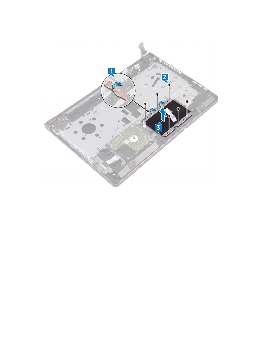
3 Lift the touch-pad bracket o the palm-rest assembly.
82
Page 83

4 Lift the touch pad o the palm-rest assembly.
83
Page 84

Replacing the touchpad
WARNING: Before working inside your computer, read the safety
information that shipped with your computer and follow the steps in Before
working inside your computer. After working inside your computer, follow
the instructions in After working inside your computer. For more safety best
practices, see the Regulatory Compliance home page at
regulatory_compliance.
Procedure
1 Place the touch pad on the palm-rest assembly.
2 Align the screw holes on the touch-pad bracket with the screw holes on the
palm-rest assembly.
3 Replace the six screws (M2x3) that secure the touch-pad bracket to the touch
pad.
4 Adhere the tape that secures the touch-pad bracket to the palm-rest assembly.
Post-requisites
1 Replace the system board.
2 Replace the fan.
3 Replace the heat sink.
4 Replace the wireless card.
5 Replace the memory modules.
6 Follow the procedure from step 2 to step 8 in “Replacing the base cover”.
7 Replace the keyboard.
8 Follow the procedure from step 4 to step 5 in “Replacing the optical drive”.
9 Replace the battery.
www.dell.com/
84
Page 85

Removing the power-adapter port
WARNING: Before working inside your computer, read the safety
information that shipped with your computer and follow the steps in Before
working inside your computer. After working inside your computer, follow
the instructions in After working inside your computer. For more safety best
practices, see the Regulatory Compliance home page at
regulatory_compliance.
Prerequisites
1 Remove the battery.
2 Follow the procedure from step 1 to step 3 in “Removing the optical drive”.
3 Remove the keyboard.
4 Follow the procedure from step 1 to step 7 in “Removing the base cover”.
5 Remove the coin-cell battery.
6 Remove the memory modules.
7 Remove the wireless card.
8 Remove the heat sink.
9 Remove the fan.
10 Remove the system board.
www.dell.com/
Procedure
1 Remove the screw (M2x3) that secures the power-adapter port to the palm-
rest assembly.
2 Note the power-adapter port cable routing and remove the cable from its
routing guides.
85
Page 86
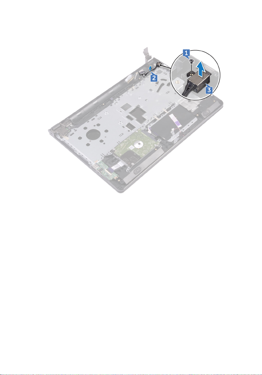
3 Lift the power-adapter port o the palm-rest assembly.
86
Page 87

Replacing the power-adapter port
WARNING: Before working inside your computer, read the safety
information that shipped with your computer and follow the steps in Before
working inside your computer. After working inside your computer, follow
the instructions in After working inside your computer. For more safety best
practices, see the Regulatory Compliance home page at
regulatory_compliance.
Procedure
1 Slide the power-adapter port into the slot on the palm-rest assembly.
2 Replace the screw (M2x3) that secures the power-adapter port to the palm-
rest assembly.
3 Route the power-adapter port cable along its routing guides on the palm-rest
assembly.
Post-requisites
1 Replace the system board.
2 Replace the fan.
3 Replace the heat sink.
4 Replace the wireless card.
5 Replace the memory modules.
6 Replace the coin-cell battery.
7 Follow the procedure from step 2 to step 8 in “Replacing the base cover”.
8 Replace the keyboard.
9 Follow the procedure from step 4 to step 5 in “Replacing the optical drive”.
10 Replace the battery.
www.dell.com/
87
Page 88

Removing the display assembly
WARNING: Before working inside your computer, read the safety
information that shipped with your computer and follow the steps in Before
working inside your computer. After working inside your computer, follow
the instructions in After working inside your computer. For more safety best
practices, see the Regulatory Compliance home page at
regulatory_compliance.
Prerequisites
1 Remove the battery.
2 Follow the procedure from step 1 to step 3 in “Removing the optical drive”.
3 Remove the keyboard.
4 Follow the procedure from step 1 to step 7 in “Removing the base cover”.
5 Remove the wireless card.
Procedure
1 Remove the three screws (2.5x8) that secure the display hinges to the palm-
rest assembly.
www.dell.com/
88
Page 89

2 Open the display hinges to an angle of 90 degrees.
3 Peel the tape that secures the display cable to the palm-rest assembly.
4 Open the latch and disconnect the display cable.
5 Note the display cable routing and remove the display cable from the routing
guides on the palm-rest assembly.
89
Page 90

6 Note the antenna cable routing and remove the cable from its routing guides on
the palm-rest assembly.
90
Page 91

7 Open the palm-rest assembly at an angle and slide it o the display assembly.
91
Page 92

Replacing the display assembly
WARNING: Before working inside your computer, read the safety
information that shipped with your computer and follow the steps in Before
working inside your computer. After working inside your computer, follow
the instructions in After working inside your computer. For more safety best
practices, see the Regulatory Compliance home page at
regulatory_compliance.
Procedure
1 Place the display assembly on a clean, at surface.
2 Place the palm-rest assembly on the display assembly.
3 Close the display hinges and align the screw holes on the display hinges with the
screw holes on the palm-rest assembly.
4 Replace the three screws (2.5x8) that secure the display hinges to the palm-
rest assembly.
5 Route the antenna cables through the routing guides on the palm-rest assembly.
6 Connect the display cable and close the latch to secure the cable.
7 Route the display cable through the routing guides on the palm-rest assembly.
8 Adhere the tape that secures the display cable to the palm-rest assembly.
9 Close the display and turn the computer over.
www.dell.com/
Post-requisites
1 Replace the wireless card.
2 Follow the procedure from step 2 to step 8 in “Replacing the base cover”.
3 Replace the keyboard.
4 Follow the procedure from step 4 to step 5 in “Replacing the optical drive”.
5 Replace the battery.
92
Page 93

Removing the display bezel
WARNING: Before working inside your computer, read the safety
information that shipped with your computer and follow the steps in Before
working inside your computer. After working inside your computer, follow
the instructions in After working inside your computer. For more safety best
practices, see the Regulatory Compliance home page at
regulatory_compliance.
Prerequisites
NOTE: These instructions are applicable only for laptops with a non-touch
screen display.
1 Remove the battery.
2 Follow the procedure from step 1 to step 3 in “Removing the optical drive”.
3 Remove the keyboard.
4 Follow the procedure from step 1 to step 7 in “Removing the base cover”.
5 Remove the wireless card.
6 Remove the display assembly.
www.dell.com/
93
Page 94

Procedure
1 Using your ngertips, carefully pry up the inner edges of the display bezel.
2 Remove the display bezel o the display back-cover and antenna assembly.
94
Page 95

Replacing the display bezel
WARNING: Before working inside your computer, read the safety
information that shipped with your computer and follow the steps in Before
working inside your computer. After working inside your computer, follow
the instructions in After working inside your computer. For more safety best
practices, see the Regulatory Compliance home page at
regulatory_compliance.
Procedure
Align the display bezel with the display back-cover and gently snap the display bezel
into place.
Post-requisites
1 Replace the display assembly.
2 Replace the wireless card.
3 Follow the procedure from step 2 to step 8 in “Replacing the base cover”.
4 Replace the keyboard.
5 Follow the procedure from step 4 to step 5 in “Replacing the optical drive”.
6 Replace the battery.
www.dell.com/
95
Page 96

Removing the display panel
WARNING: Before working inside your computer, read the safety
information that shipped with your computer and follow the steps in Before
working inside your computer. After working inside your computer, follow
the instructions in After working inside your computer. For more safety best
practices, see the Regulatory Compliance home page at
regulatory_compliance.
Prerequisites
NOTE: These instructions are applicable only for laptops with a non-touch
screen display.
1 Remove the battery.
2 Follow the procedure from step 1 to step 3 in “Removing the optical drive”.
3 Remove the keyboard.
4 Follow the procedure from step 1 to step 7 in “Removing the base cover”.
5 Remove the wireless card.
6 Remove the display assembly.
7 Remove the display bezel.
Procedure
www.dell.com/
1 Remove the four screws (M2x3) that secure the display panel to the display
back-cover and antenna assembly.
96
Page 97

2 Lift the display panel and turn it over.
3 Peel the tape that secures the display cable to the display panel.
4 Open the latch and disconnect the display cable from the display panel.
97
Page 98

5 Lift the display panel o the display back-cover and antenna assembly.
98
Page 99

Replacing the display panel
WARNING: Before working inside your computer, read the safety
information that shipped with your computer and follow the steps in Before
working inside your computer. After working inside your computer, follow
the instructions in After working inside your computer. For more safety best
practices, see the Regulatory Compliance home page at
regulatory_compliance.
Post-requisites
1 Replace the display bezel.
2 Replace the display assembly.
3 Replace the wireless card.
4 Follow the procedure from step 2 to step 8 in “Replacing the base cover”.
5 Replace the keyboard.
6 Follow the procedure from step 4 to step 5 in “Replacing the optical drive”.
7 Replace the battery.
Procedure
1 Slide the display cable into the connector on the display panel and close the
latch to secure the cable.
2 Adhere the tape that secures the display cable to the display panel.
3 Turn the display panel over and place it on the display back-cover and antenna
assembly.
4 Align the screw holes on the display panel with the screw holes on the display
back-cover and antenna assembly.
5 Replace the four screws (M2x3) that secure the display panel to the display
back-cover and antenna assembly.
www.dell.com/
99
Page 100

Removing the camera
WARNING: Before working inside your computer, read the safety
information that shipped with your computer and follow the steps in Before
working inside your computer. After working inside your computer, follow
the instructions in After working inside your computer. For more safety best
practices, see the Regulatory Compliance home page at
regulatory_compliance.
Prerequisites
NOTE: These instructions are applicable only for laptops with a nontouchscreen display.
1 Remove the battery.
2 Follow the procedure from step 1 to step 3 in “Removing the optical drive”.
3 Remove the keyboard.
4 Follow the procedure from step 1 to step 7 in “Removing the base cover”.
5 Remove the wireless card.
6 Remove the display assembly.
7 Remove the display bezel.
Procedure
www.dell.com/
1 Using a plastic scribe, gently pry the camera and lift it at an angle.
2 Disconnect the camera cable from the camera.
100
 Loading...