

Page 1

Dell™Inspiron™3500PortableComputerSystemReference
Information in this document is subject to change without notice.
©1999 Dell Computer Corporation. All rights reserved.
Reproduction in any manner whatsoever without the written permission of Dell Computer Corporation is strictly forbidden.
Trademarks used in this text: Dell, the DELL logo, and InspironaretrademarksofDellComputerCorporation;Microsoft, Windows, MS-DOS, and Windows NT are registered
trademarks of Microsoft Corporation; Intel is a registered trademark and Celeron is a trademark of of Intel Corporation; VESA is a registered trademark of Video Electronics
Standards Association; DVD-to-Go is a trademark of Margi Systems, Inc.; Adobe is a trademark of Adobe Systems Incorporated, which may be registered in certain
jurisdictions.
Other trademarks and trade names may be used in this document to refer to either the entities claiming the marks and names or their products. Dell Computer Corporation
disclaims any proprietary interest in trademarks and trade names other than its own.
Initial release: 25 Jun 1999
Last revised: 11 Aug 1999
Conventions
Technical Overview
Jumpers, Switches, Controls, and Indicators
Utilities and Drivers
Setup Program
Technical Specifications
Removing and Replacing Parts
Documentation
Glossary
Page 2

AC Adapter: Dell™ Inspiron™ 3500 Portable Computer
Page 3
Audio Jacks: Dell™ Inspiron™ 3500 Portable Computer
Page 4

Audio: Dell™ Inspiron™ 3500 Portable Computer
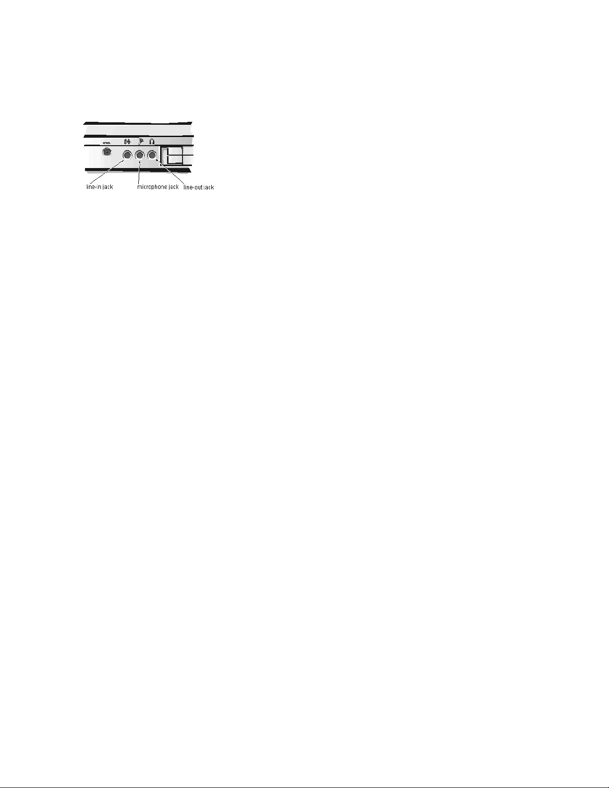
You can connect speakers, a microphone, headphones, and record/playback devices such as cassette players, CD players, and VCRs to the sound jacks on the
computer. Dell recommends using amplified speakers for the best sound.
Connect headphones or speakers to the line-out jack on the far right of the sound jacks. Connect a microphone to the microphone jack in the middle. Connect
record/playbackdevicessuchascassetteplayersandCDplayerstotheline-in jack on the far left.
You can control the sound coming from the external speakers and from the computer's built-in speakers with key combinations. Press <Fn><Page Down> to lower the
volume. Press <Fn><Page Up> to increase the volume. Press <Fn><End> to enable or disable both the built-in and external speakers.
See your Microsoft® Windows® 98 documentation for the location of sound applications such as mixers and volume control.
The MagicWave 3DX Config utility allows you to increase the microphone gain by 20 dB and configure the tone (treble, bass and 3D enhancement) settings.
To launch the utility, perform the following steps:
1. Click the Start button, point to Settings, and then click Control Panel.
The Control Panel window appears.
2. Double-click MagicWave 3DX Config.
See Installing Utilities and Drivers for information about installing or reinstalling audio drivers.
NOTES: If no sound comes from the speakers, make sure that the sound is not disabled by pressing <Fn><End>.
Ifyouhearnosoundoutputfromyourexternalspeakersbesurethattheconnectiontothesoundoutputjackissecure.IfyouareplayingaDVDin
the optional DVD-ROM drive and have speakers that connect to your computer through the USB port, no sound will be output to the speakers. This
configurationisnotsupported.
Page 5
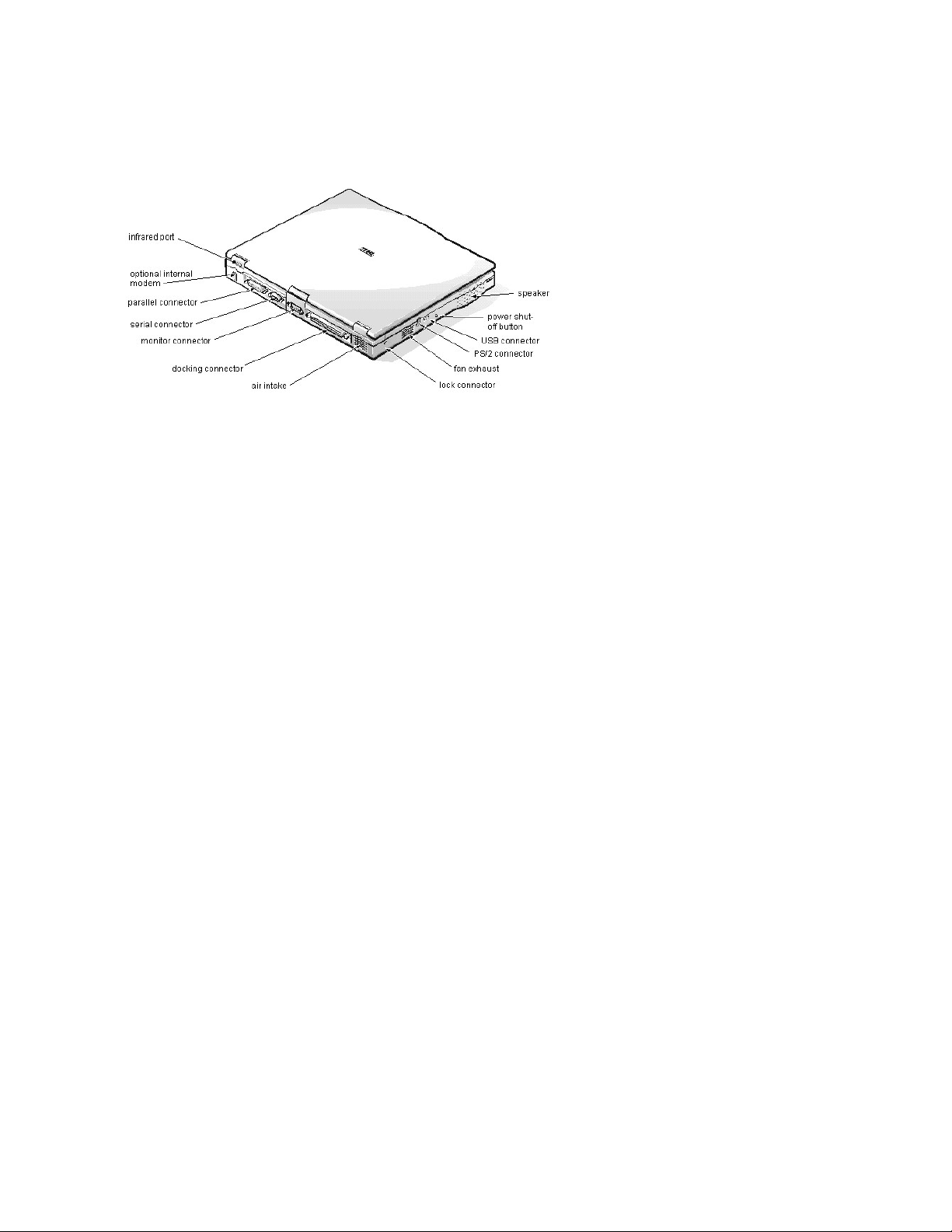
Component Locations (Back View): Dell™ Inspiron™ 3500 Portable Computer
Page 6

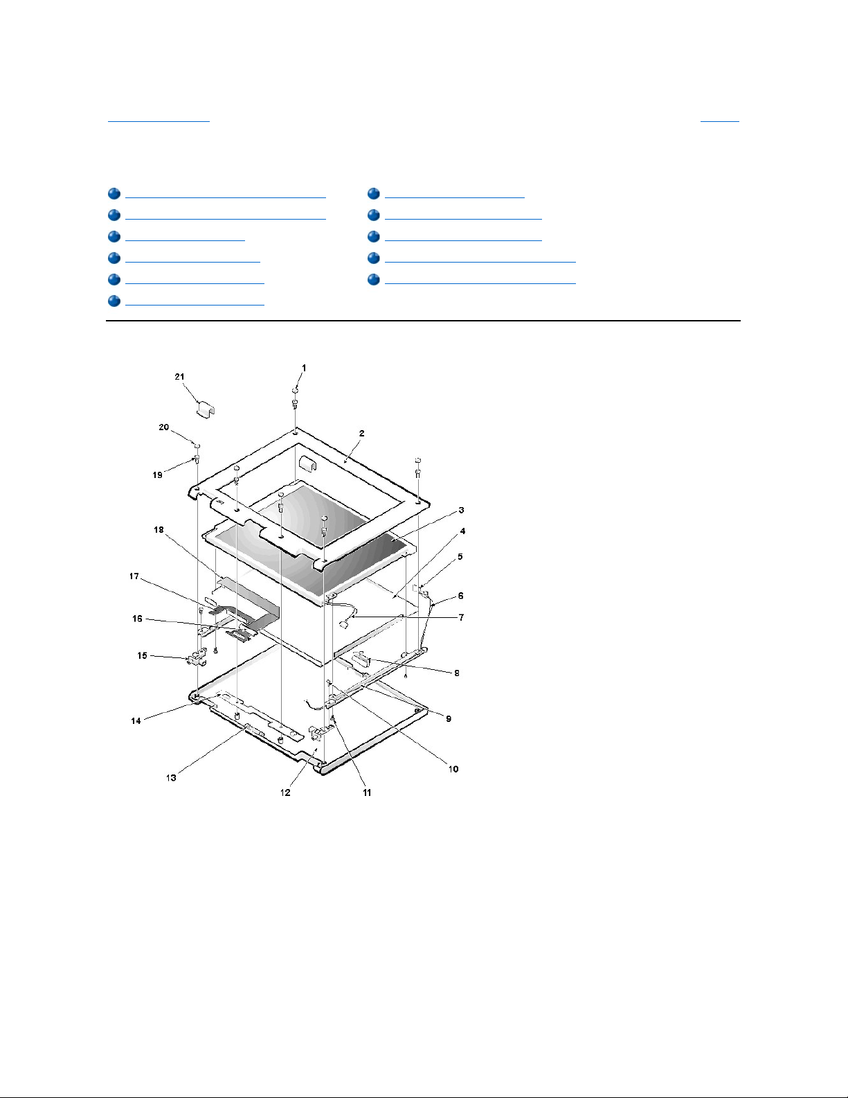
BaseAssembly:Dell™Inspiron™3500PortableComputer
Exploded View of Base Assembly
Back to Contents Page
Glossary
Exploded View of Base Assembly
Video Board Removal
Keyboard Removal
System Board Rails Removal
Infrared Board Removal
DC/DC Board Removal
LVDS Board Removal
Speaker Removal
Heat-Sink Fin Cover Removal
PC Card Cage Removal
Processor Module Assembly Removal
System Board Removal
Fan Cover and Fan Removal
Audio-Jack Board Removal
Modem Card Removal
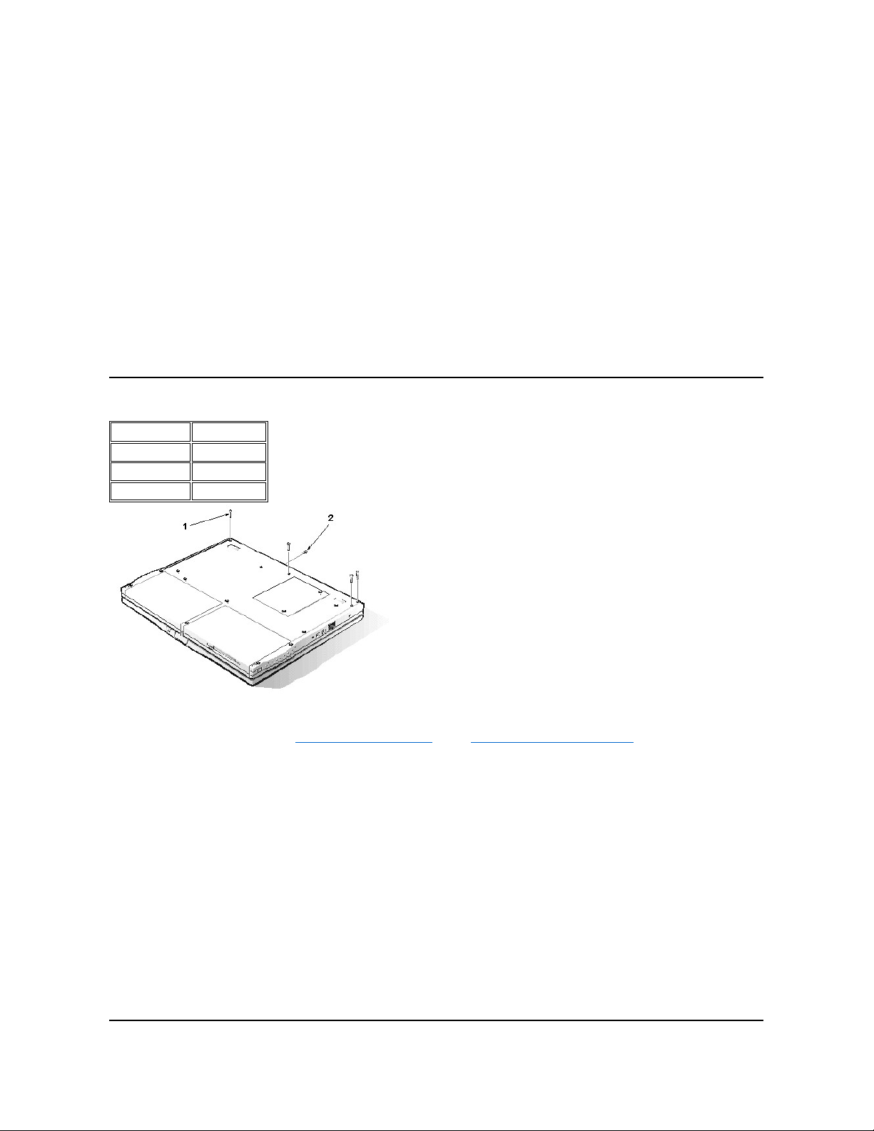
1
Ground springs (2)
2
Infrared board with 5-mm screw
3
Optional internal modem with 14-mm screw
4
EMI fin (2)
5
LVDS board
6
Video board with 4-mm jack screws (2) and 14-mm screw
Page 7
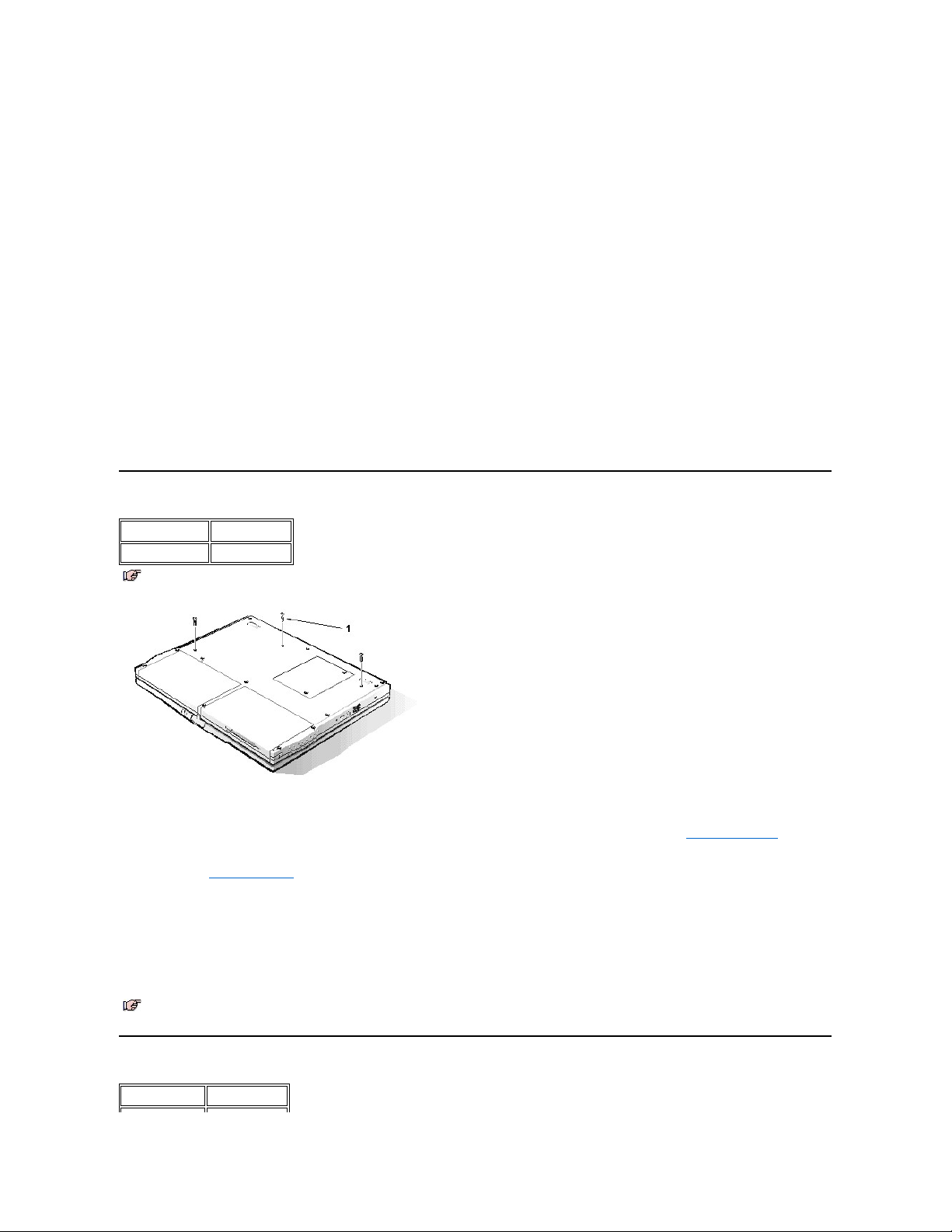
Keyboard Removal
You can remove the keyboard without removing the palmrest. To remove the keyboard, see the exploded view of the palmrest assembly and
perform the following steps:
1. Remove the display assembly.
2. Place the computer base face down.
3. Remove the three 16-mm keyboard screws from the bottom of the computer.
The keyboard screws have a K tooled into the plastic beside them.
4. Turn the computer face up.
5. Lift the top edge of the keyboard up, and then slide the keyboard out from beneath the palmrest assembly.
Do not try to completely remove the keyboard, because it is still attached to the system board by a cable.
6. Disconnect the keyboard cable from the side-lift ZIF connector C42 on the system board.
7. Remove the keyboard.
Infrared Board Removal
7
PC Card cage with 14-mm screws (4)
8
Monitor connector cover
9
DC/DC board with 14-mm screw
10
Audio jack board
11
Audio jack shield
12
System-board retaining clip with 5-mm screw
13
Bottom plastic
14
Release latches
15
Speakers
16
system board (in EMI pan)
17
Fan and fan cover with 5-mm screw
18
Heat-sink fin
19
Processor module assembly with 14-mm screws (2)
20
System-board retaining clip with 14-mm screw
21
System board rails (2) with 5-mm screws (2) and 16-mm screw
Type of Screw
Torque
FPH 2.5 x 16 (3)
3.5–4.0 kgf-cm
NOTE: You can remove the keyboard while the display assembly is still attached. However, Dell strongly recommends removing the
display assembly before removing the keyboard to prevent cosmetic damage.
1
16-mm screws (3)
NOTE: The ZIF connector cap for the keyboard is stocked as a separate part. If the plastic connector cap is broken, you can snap a new
one in place without having to replace the entire system board.
Type of Screw
Torque
Page 8
You can remove the infrared (IR) board without removing the palmrest. To remove the infrared board, see the exploded view of the base assembly
and perform the following steps:
1. Remove the display assembly.
2. Remove the 5-mm screw securing the IR board to the right system board rail.
3. Lift the IR board to expose the wires.
4. Disconnect the IR cable from connector J4 on the system board.
5. Remove the IR board.
LVDS Board Removal
You can remove the LVDS board without removing the palmrest. To remove the LVDS board, see the exploded view of the base assembly and
perform the following steps:
1. Remove the display assembly.
2. Remove the keyboard.
3. Carefully lift the LVDS board off of connectors J2 and J3 on the video board.
The board is surrounded by an EMI fence.
When installing the LVDS board, put pressure only on the areas where the connectors on the LVDS board and on the video board fit together.
Pressing on other areas may flex the board and break connections.
Heat-Sink Fin Cover Removal
You can remove the heat-sink fin cover without removing the palmrest. To remove the heat-sink fin cover, see the exploded view of the base
assembly and perform the following steps:
1. Remove the keyboard.
2. Remove the 3.5-mm screw securing the cover to the heat-sink fin.
3. Remove the heat-sink fin cover.
Processor Module Assembly Removal
You can remove the processor module assembly without removing the palmrest. To remove the processor module assembly, see the exploded
view of the base assembly and perform the following steps:
1. Remove the keyboard.
2. Remove the heat-sink fin cover.
3. Remove the two 14-mm screws securing the processor module assembly to the system board.
4. Lift the processor module assembly off of connector U14 on the system board.
Lift from the outside first.
5. To disassemble the processor module assembly, slide the top plate free of the interlock tabs.
The assembly separates into upper and lower plates and reveals the processor module.
6. Remove and replace the thermal pads only if needed.
The pink pad covers the BX chip and the gray pad covers the processor chip.
When you install the processor module assembly, put pressure only on the areas where the connectors on the processor module assembly and on
the system board fit together. Pressing on other areas may break pins or connections.
FPH 2.5 x 5 (1)
3.0–3.5 kgf-cm
NOTE: Reconnect the IR board to the system board by carefully threading the wires and connector by the I/O bracket and using a
screwdriver to press on the connector to reseat it.
NOTE: For grounding purposes, an EMI tape may run from the LVDS board to the I/O bracket. Note the placement of the tape and,
during installation, replace it in the same position.
NOTE: The LVDS board is unique for each type of LCD panel. During installation, make sure that the LVDS board is the correct one for
the panel and that any EMI tape attached to the board is replaced in its original position.
Type of Screw
Torque
FPH 2 x 3.5 (1)
1.5–1.8 kgf-cm
Type of Screw
Torque
PNH 2 x 14 (2)
1.5–1.8 kgf-cm
Page 9
Fan Cover and Fan Removal
You can remove the fan cover and fan without removing the palmrest. To remove the fan cover and fan, see the exploded view of the base
assembly and perform the following steps:
1. Remove the display assembly.
2. Remove the keyboard.
3. Remove the heat-sink fin cover.
4. Remove the 5-mm screw securing the fan cover.
5. Remove the fan cover.
6. Disconnect the fan cable from connector J6 on the system board.
7. Remove the fan.
Modem Card Removal
The modem card is an option available only to customers in the U.S. and Canada.
You can remove the modem card without removing the palmrest. To remove the modem card, see the exploded view of the base assembly and
perform the following steps:
1. Remove the keyboard.
2. Remove the 14-mm screw from the right side of the modem card.
3. Pry up the modem card from the right side.
4. Disconnect the modem cable from connector J2 on the modem card.
5. Remove the modem card.
When you install the modem card, slip it into place under the system-board retaining clip. Put pressure only on the areas where the connectors on
the modem card and on the video board fit together. Pressing on other areas may flex the card and break connections.
Video Board Removal
You can remove the video board without removing the palmrest. To remove the video board, see the exploded view of the base assembly and
perform the following steps:
1. Remove the display assembly.
2. Remove the keyboard.
3. Remove the LVDS board.
4. Remove the modem card, if present.
5. Remove (and save for installation) any Kapton tape securing the modem cable to the video board and lift the cable out of the way.
6. Remove the two 4-mm jack screws on either side of the display connector that hold the video board to the I/O bracket.
7. Disconnect the touch-pad FPC cable from the side-lift ZIF connector J4 on the video board.
8. Remove the 14-mm screw holding the system-board retaining clip.
Remove both the screw and the retaining clip.
9. Remove the video board from connectors JP2 and JP3/JP4 on the system board.
Lift the end toward the touch pad up, and then lift up and pull back the other end to free it from the I/O bracket.
When you install the board, put pressure only on the areas where the connectors on the video board and on the system board fit together. Pressing
on other areas may flex the board and break connections.
System Board Rails Removal
Type of Screw
Torque
FPH 2.5 x 5 (1)
3.0–3.5 kgf-cm
NOTE: Note the positioning of the fan and the routing of the fan cable carefully so that you can duplicate it during installation. An arrow on
the top of the fan indicates that the flow of air is from the outside of the computer in to the board.
Type of Screw
Torque
FPH 2.5 x 14 (1)
3.0–3.5 kgf-cm
Type of Screw
Torque
jack 2.5 x 4 (2)
3.0–3.5 kgf-cm
FPH 2.5 x 14 (1)
3.0–3.5 kgf-cm
Type of Screw
Torque
Page 10

To remove the system board rails, see the exploded view of the base assembly and perform the following steps:
1. Remove the display assembly.
2. Remove the keyboard.
3. Remove the palmrest assembly.
4. Remove the infrared board.
5. Remove the 5-mm screw and the 16-mm screw securing the right system-board rail.
6. Remove the right system-board rail.
7. Remove the 5-mm screw securing the left system-board rail.
8. Remove the left system-board rail.
9. Remove the release latches for the battery bay and media bay, which were previously held in place by the system board rails.
10. Remove the heat sink.
When you install the rails, be sure that the speaker cables are not pinched.
DC/DC Board Removal
To remove the DC/DC board, see the exploded view of the base assembly and perform the following steps:
1. Remove the display assembly.
2. Remove the keyboard.
3. Remove the palmrest assembly.
4. Remove the system board rails.
5. Remove the 14-mm screw.
6. Gently lift the DC/DC board off of the connector on the system board.
When you install the board, put pressure only on the areas where the connectors on the DC/DC board and on the system board fit together.
Pressing on other areas may flex the board and break connections.
Speaker Removal
To remove the speakers, see the exploded view of the base assembly and perform the following steps:
1. Remove the display assembly.
2. Remove the keyboard.
3. Remove the palmrest assembly.
4. Remove the system board rails.
5. Remove the DC/DC board.
6. Disconnect the left speaker cable from connector J13 on the system board.
7. Disconnect the right speaker cable from connector J15 on the system board.
8. Lift the speakers and cables out of the bottom plastic.
PC Card Cage Removal
The PC Card cage is supplied as a part of the system board assembly. However, if only the PC Card cage needs replacement, use this procedure
to remove and replace the PC Card cage. You do not need to remove the entire system board.
To remove the PC Card cage, see the exploded view of the base assembly and perform the following steps:
1. Remove the display assembly.
2. Remove the keyboard.
3. Remove the palmrest assembly.
4. Remove the system board rails.
5. Remove the LVDS board, modem card (if present), and video board.
6. Remove the four 14-mm screws securing the PC Card cage to the system board.
FPH 2.5 x 5 (2)
3.0–3.5 kgf-cm
FPH 2.5 x 16 (1)
3.0–3.5 kgf-cm
Type of Screw
Torque
FPH 2.5 x 14 (1)
3.0–3.5 kgf-cm
NOTE: The left and right speakers are interchangeable. Note the routing of the speaker cables through the plastic routing ribs for
installation.
Type of Screw
Torque
PNH 2 x 14 (4)
1.5–1.8 kgf-cm
Page 11

7. Remove the PC Card cage.
When you install the PC Card cage, ensure that the modem cable is routed correctly and is not pinched by the cage.
System Board Removal
To remove the system board, see the exploded view of the base assembly and perform the following steps:
1. Remove the display assembly.
2. Remove the keyboard.
3. Remove the infrared board, LVDS board, heat-sink fin cover, processor module assembly, fan cover and fan, modem card (if present), and
video board.
4. Removed the palmrest assembly.
5. Remove the system board rails.
6. Remove the DC/DC board.
7. Disconnect the speaker cables.
8. Remove the heat-sink fin.
9. Remove the 5-mm screw from the upper right corner of the system board.
10. Remove the system board retaining clip that was held in place by this screw.
11. Remove the 14-mm screw used for grounding on the lower left corner of the system board.
12. Remove the system board by lifting up the back of the board/EMI pan so that it clears all of the bottom plastic, and then pulling back to free
the I/O connectors from the bottom plastic. The EMI shield is still attached to the system board.
Audio-Jack Board Removal
To remove the audio jack board, see the exploded view of the base assembly and perform the following steps:
1. Remove the display assembly.
2. Remove the keyboard.
3. Remove the palmrest assembly.
4. Remove the system board rails.
5. Remove the DC/DC board.
6. Disconnect the speaker cables.
7. Remove the system board.
8. Remove the audio jack shielding that covers the audio jacks on three sides. Note that the shielding wraps around and goes beneath the
system board and the EMI pan, not between the board and the pan.
9. Lift the audio jack board off of connectors J16 and J11 on the system board.
When you install the audio jack board, it is helpful to move the PC Card latches out of the way. Put pressure only on the areas where the
connectors on the audio jack board and on the system board fit together. Pressing on other areas may bend the board and break connections.
Type of Screw
Torque
FPH 2.5 x 5 (1)
3.0–3.5 kgf-cm
FPH 2.5 x 14 (1)
3.0–3.5 kgf-cm
Back to Contents Page
Glossary
Page 12
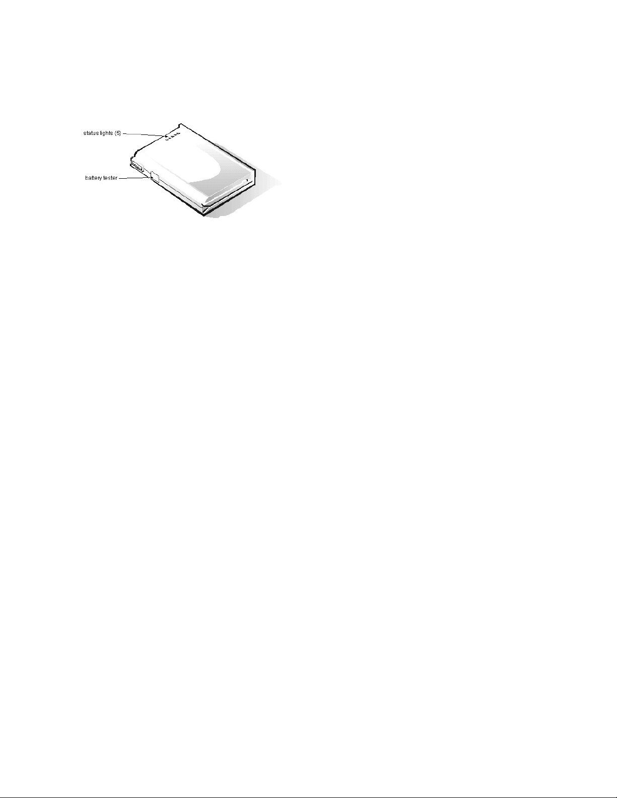
Battery Charge Gauge: Dell™ Inspiron™ 3500 Portable Computer
Page 13
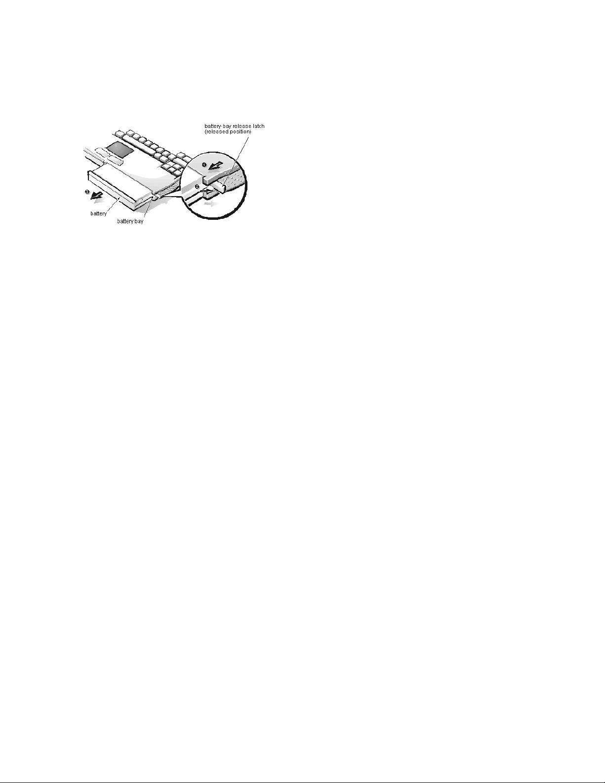
Removing and Installing a Battery: Dell™ Inspiron™ 3500 Portable Computer
Page 14

Conventions: Dell™Inspiron™3500PortableComputerSystemReference
The following subsections describe notational conventions used in this document.
Notes, Notices, and Cautions
Throughout this guide, blocks of text may be accompanied by an icon and printed in bold type or in italic type. These blocks are notes, notices, and
cautions, and they are used as follows:
NOTICE: A NOTICE indicates either potential damage to hardware or loss of data and tells you how to avoid the problem.
Typographical Conventions
The following list defines (where appropriate) and illustrates typographical conventions used as visual cues for specific elements of text throughout
this document:
l Interface components are window titles, button and icon names, menu names and selections, and other options that appear on the monitor
screen or display. They are presented in bold.
Example: Click OK.
l Keycaps are labels that appear on the keys on a keyboard. They are enclosed in angle brackets.
Example: <Enter>
l Key combinations are series of keys to be pressed simultaneously (unless otherwise indicated) to perform a single function.
Example: <Ctrl><Alt><Enter>
l Commands presented in lowercase bold are for reference purposes only and are not intended to be typed when referenced.
Example: “Use the format command to . . . .”
In contrast, commands presented in the Courier New font are part of an instruction and intended to be typed.
Example: “Type format a: to format the diskette in drive A.”
l Filenames and directory names are presented in lowercase bold.
Examples: autoexec.bat and c:\windows
l Screen text is a message or text that you are instructed to type as part of a command (referred to as a command line). Screen text is
presented in the Courier New font.
Example: The following message appears on your screen:
No boot device available
Example: “Type md c:\programs and press <Enter>.”
l Variables are placeholders for which you substitute a value. They are presented in italics.
Example: DIMM_x (where x represents the DIMM socket designation)
Back to Contents Page
Glossary
Notes, Notices, and Cautions
Typographical Conventions
NOTE: A NOTE indicates important information that helps you make better use of your computer system.
CAUTION: A CAUTION indicates a potentially hazardous situation which, if not avoided, may result in minor or moderate injury.
Back to Contents Page
Glossary
Page 15
13.3- and 14.1-InchDisplayAssemblies:Dell™Inspiron™3500PortableComputer
System Reference
Exploded View of 13.3-Inch Display Assembly
Back to Contents Page
Glossary
Exploded View of 13.3-Inch Display Assembly
LCD Interior Assembly Removal
Exploded View of 14.1-Inch Display Assembly
13.3-Inch LCD Panel Rails Removal
Display Assembly Removal
14.1-Inch LCD Panel Rails Removal
Bezel and LCD Latch Removal
13.3-Inch LCD Panel and EMI Pan Removal
13.3-Inch LCD Inverter Removal
14.1-Inch LCD Panel and EMI Pan Removal
14.1-Inch LCD Inverter Removal
1
Rubber bumpers (2)
2
Bezel3LCD panel
4
EMI pan
5
LED card
6
LED cable
7
LCD cable
8
LCD latch
9
Panel rails (2)
Page 16

Exploded View of 14.1-Inch Display Assembly
10
5-mm hinge screws (2)
11
5-mm panel rail screws (4)
12
Back cover
13
Bottom FPC bobbin
14
Inverter
15
Hinges (2)
16
Top FPC bobbin
17
Inverter signal cable
18
LCD FPC cable
19
5-mm bezel screws (6)
20
Screw covers (4)
21
Hinge covers (2)
1
Rubber bumpers (2)
2
Bezel3LCD panel
4
EMI pan
5
LED card
6
LED cable
7
LCD cable
8
LCD latch
Page 17
Display Assembly Removal
To remove the display assembly, see the exploded view of the computer and the exploded view of the base assembly and perform the following
steps:
1. Close the computer and place it upside down.
2. Remove the four 19-mm display screws from the bottom of the computer.
The display screws have a D tooled into the base plastic beside them. Once the screws are removed, the display assembly is very loose.
3. Hold the computer firmly and turn it over.
4. Remove the top half of the cover over the monitor connector.
This connector is on the back of the computer.
5. Remove the 5-mm screw that was beneath the cover.
6. Unlatch the LCD latch.
7. Slowly open the display assembly so it is at a 90-degree angle to the base.
This action repositions the hinges so you can remove the bezel later.
8. Gently lift the display assembly so the hinges are free of the base.
Do not lift the assembly too far up because the LCD FPC cable is still connected to the LVDS board.
The FPC bobbin and hinge covers lift up with the assembly; the connector cover may lift up with the assembly.
9. Place the display assembly on a support so that the LCD FPC cable is not stressed.
10. Remove the connector cover to expose the end of the LCD FPC cable that connects to the system board.
11. Remove the two 2.5-mm screws securing the LCD FPC cable connector to the LVDS board, and gently lift the connector off of connector
C24 on the LVDS board.
The display assembly is now free from the base. The hinge covers may remain in place.
12. Remove the ground springs from the holes in the system board rails in the base of the computer.
These fall out easily when the computer is turned upside down.
9
Right panel rail
10
4-mm panel rail screws (4)
11
Back cover
12
Bottom FPC bobbin
13
Inverter
14
Top FPC bobbin
15
Hinges (2)
16
Inverter signal cable
17
Left panel rail
18
5-mm hinge screws (2)
19
LCD FPC cable
20
5-mm bezel screws (6)
21
Hinge covers (4)
22
Hinge covers (2)
Type of Screw
Torque
FLH 2.5 x 19 (4)
1.5–2.0 kgf-cm
2.5 x 5 (1)
2.0–2.5 kgf-cm
FPH 2 x 2.5 (2)
1.5–1.8 kgf-cm
1
19-mm screws (4)
2
5-mm screw
Page 18

Bezel and LCD Latch Removal
To remove the bezel and LCD latch, see the exploded view of the 13.3-inch display assembly or 14.1-inch display assembly and perform the
following steps:
1. Remove the display assembly.
2. Use the dental pick to remove the four screw covers from the bottom of the bezel.
Take care not to cause cosmetic damage and not to put pressure on the LCD panel.
3. Remove the two rubber bumpers from the top of the bezel.
Take care not to cause cosmetic damage and not to put pressure on the LCD panel.
4. Remove the six 5-mm screws securing the bezel to the display assembly.
5. Remove the bezel.
Unfasten the snaps at the bottom of the bezel by applying light pressure on the inside bottom edge of the bezel and pulling the bezel slightly
up and toward you. Hold the LCD latch out of the way when removing the top of the bezel.
6. Insert a small, flat blade at the top of the latch and pry the latch up from the retainer in the back cover.
You may be able to rotate the LCD latch inward to release it from the retainer in the back cover.
13.3-Inch LCD Inverter Removal
To remove the inverter, see the exploded view of the 13.3-inch display assembly and perform the following steps:
1. Remove the display assembly.
2. Remove the bezel.
3. Disconnect the inverter signal cable from the side-lift ZIF connector CN1 on the left side of the inverter by gently pulling each side of the ZIF
connector, and then pulling out the cable.
4. Disconnect the LED cable from connector CN3 on the inverter.
5. Disconnect the LCD cable from connector CN2 on the inverter. (A red dot denotes the top of the LCD cable connector when you are
installing the cable.)
6. Remove the inverter.
14.1-Inch LCD Inverter Removal
To remove the inverter, see the exploded view of the 14.1-inch display assembly and perform the following steps:
1. Remove the display assembly.
2. Remove the bezel.
3. Disconnect the inverter signal cable from the side-lift ZIF connector CN1 on the left side of the inverter by gently pulling each side of the ZIF
connector, and then pulling out the cable.
4. Disconnect the wraparound LCD FPC cable on the left side of the inverter. The cable wraps around the inverter and connects to itself.
5. Remove (and save for installation) any Kapton tape securing cables on the right side of the inverter.
6. Lift the inverter partially up to make disconnecting the remaining cables easier.
7. Disconnect the LED cable from connector CN3 on the right side of the inverter.
8. Disconnect the LCD cable from connector CN2 on the right side of the inverter.
9. Remove the inverter.
LCD Interior Assembly Removal
To remove the LCD interior assembly from the back cover, see the exploded view of the 13.3-inch display assembly or the exploded view of the
14.1-inch display assembly and perform the following steps:
1. Remove the display assembly.
2. Remove the bezel.
3. Remove the left and right hinge covers.
Type of Screw
Torque
FPH 2.5 x 5 (6)
3.5–4.0 kgf-cm
CAUTION: The following procedure should be performed only by depot repair technicians.
CAUTION: The following procedure should be performed only by depot repair technicians.
CAUTION: The following procedure should be performed only by depot repair technicians.
Type of Screw
Torque
FPH 2.5 x 5 (2)
3.5–4.0 kgf-cm
Page 19
4. Remove the two 5-mm screws securing the left and right hinges, and then remove the hinges.
The hinges are not interchangeable, but are color-coded; the nut on the right hinge is gold and, on the left, silver.
5. Remove the top half of the FPC bobbin by inserting a flat blade into the bobbin and carefully prying the top and bottom apart.
6. If you have not removed the inverter, lift it up slightly (it is still connected to the LCD).
7. Slide the entire LCD interior assembly (which includes the LCD panel, panel rails, EMI pan, and LED card and cable) down to free the panel
rails from the retaining tabs in the back cover.
8. Slide the LED card out of the plastic retainer next to the LCD latch.
9. Remove (and save for installation) any Kapton tape securing the LED or LCD cable to the back cover.
10. Remove the entire LCD interior assembly from the back cover.
When installing the LCD interior assembly, place it flat into the back cover, as close to the hinge edge as possible. Then slide it upward to fit it
underneath the plastic retaining tabs.
13.3-Inch LCD Panel Rails Removal
To remove the panel rails, see the exploded view of the 13.3-inch display assembly and perform the following steps:
1. Remove the display assembly.
2. Remove the bezel.
3. Remove the LCD interior assembly.
4. Remove the LED cable from the right panel rail (optional).
5. Place the LCD interior assembly face down on a surface that will not damage the LCD.
6. Remove the two 5-mm screws securing the left panel rail.
7. Remove the left panel rail.
It is stamped with an L (left) for easy identification.
8. Remove the two 5-mm screws securing the right panel rail.
Note that these screws can be loosened so the panel rail can slide out of the slots; the screws do not have to be completely removed.
9. Remove the right panel rail.
It is stamped with an R (right) for easy identification.
During installation, the rails must fit snugly against the LCD panel so the interior assembly will fit inside the back cover.
14.1-Inch LCD Panel Rails Removal
To remove the panel rails, see the exploded view of the 14.1-inch display assembly and perform the following steps:
1. Remove the display assembly.
2. Remove the bezel.
3. Remove the LCD interior assembly.
4. Remove the LED cable from the right panel rail (optional).
5. Remove the two 4-mm screws securing the left panel rail to the side of the LCD panel.
6. Remove the left panel rail.
It is stamped with an L (left) for easy identification.
7. Remove the two 4-mm screws securing the right panel rail to the side of the LCD panel.
8. Remove the right panel rail.
It is stamped with an R (right) for easy identification.
During installation, the rails must fit snugly against the LCD panel so the interior assembly fits inside the back cover.
13.3-Inch LCD Panel and EMI Pan Removal
NOTE: For installation, remember that the foot of the left hinge cover abuts the keyboard and that the infrared lens in the right
hinge cover faces outward to receive infrared transmissions.
NOTE: Note how the screws go through the panel rails into the hinge so you will install the screws in the right place during
installation.
CAUTION: The following procedure should be performed only by depot repair technicians.
Type of Screw
Torque
FLH 2.5 x 5 (4)
1.5–1.8 kgf-cm
NOTE: Note the routing of the LED cable through the right panel rail for installation.
CAUTION: The following procedure should be performed only by depot repair technicians.
Type of Screw
Torque
FLH 2 x 4 (4)
1.5–1.8 kgf-cm
NOTE: Note the routing of the LED cable through the right panel rail for installation.
Page 20

To remove the LCD panel from the EMI pan, see the exploded view of the 13.3-inch display assembly and perform the following steps:
1. Remove the display assembly.
2. Remove the bezel.
3. Remove the LCD interior assembly.
4. Remove the panel rails.
5. Turn the LCD interior assembly face up.
6. If present, remove (and save for installation) any Kapton tape from the lower right corner of the LCD interior assembly.
7. If present, remove (and save for installation) any Kapton tape from the center left side of the LCD interior assembly.
8. Remove (and save for installation) the EMI tape from the side and the bottom of the LCD interior assembly.
9. Remove (and save for installation) any other Kapton or EMI tape securing the LCD cable to the EMI pan.
10. Lift the LCD panel partially out of the EMI pan. The LCD FPC cable is still attached to the LCD panel.
11. Remove (and save for installation) the Kapton tape securing the LCD FPC cable to the LCD panel.
12. Gently pull the LCD FPC cable out of the connector on the LCD panel.
13. Lift the LCD panel out of the EMI pan. The LCD FPC cable remains taped to the EMI pan.
14.1-Inch LCD Panel and EMI Pan Removal
To remove the LCD panel from the EMI pan, see the exploded view of the 14.1-inch display assembly and perform the following steps:
1. Remove the display assembly.
2. Remove the bezel.
3. Remove the LCD interior assembly.
4. Remove the panel rails.
5. Remove (and save for installation) the Kapton tape from the lower right corner of the LCD interior assembly.
6. Remove (and save for installation) the EMI tape from the side and the bottom of the LCD interior assembly.
7. Remove (and save for installation) any other Kapton or EMI tape securing the LCD cable to the EMI pan.
8. Lift the LCD panel out of the EMI pan.
The LCD FPC cable remains inside the EMI pan, held in place by Kapton tape.
CAUTION: The following procedure should be performed only by depot repair technicians.
NOTE: When removing the EMI tape, hold each end of the tape at all times. If one end is released, the tape curls and sticks to
itself.
CAUTION: The following procedure should be performed only by depot repair technicians.
NOTE: When removing the EMI tape, hold each end of the tape at all times. If one end is released, the tape curls and sticks to
itself.
Back to Contents Page
Glossary
Page 21

Documentation:Dell™Inspiron™3500PortableComputer
To save PDF files (files with an extension of .pdf) to your hard-disk drive, right-click the document title, click Save Target As in Microsoft® Internet
Explorer or Save Link As in Netscape Navigator, and specify a location on your hard-disk drive.
Right-click only the following links:
Reference and Troubleshooting Guide (.pdf)
Installing System Software (.pdf)
Port Replicator User's Guide (.pdf)
Service Manual (.pdf)
Setup Guide (.pdf)
ToviewaPDFfile,launchAdobe™AcrobatReader.ClickFile–> Open and select the PDF file.
To view a Help file (a file with an extension of .hlp),clickthelinkforthefile.
System User's Guide (.hlp)
You must right-click the link for a portable document format (PDF) file and save the file to your hard-disk drive. Attempting to
link directly to large PDF files causes your system to freeze.
NOTES: PDF files require Acrobat Reader, which you can download from the Adobe World Wide Web site.
Help files require winhelp.exe, which is part of the Microsoft Windows® operating system (located in the windows directory). To view
Help files online, you may need to configure winhelp.exe to work with your browser as a helper application program. See the Help
information associated with your browser for additional information.
Page 22
DriveAssemblies:Dell™Inspiron™3500PortableComputerSystemReference
Hard-Disk Drive Disassembly
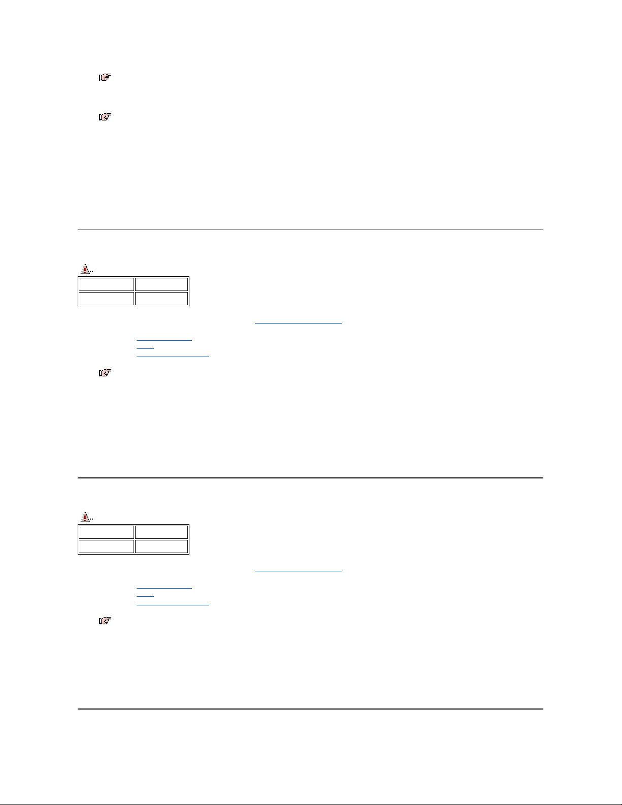
To disassemble the hard-disk drive, perform the following steps:
1. Remove the hard-disk drive from the base of the computer.
2. Remove the 4-mm screw from the side of the hard-disk drive.
3. Lift up the large plastic tab that the screw had previously secured.
There are a series of small plastic tabs along the three sides of the plastic carrier.
4. Unsnap the plastic carrier along three sides.
5. Turn the carrier over in your hand so that the hard-disk drive partially falls into your hand.
The 9.5-mm hard-disk drive uses a spacer inside the plastic carrier for proper fit.
6. Slide the hard-disk drive connector out of the plastic retainer inside the plastic carrier and remove the drive completely from the carrier.
7. Use the plastic pull to remove the flex cable from the hard-disk drive.
Diskette Drive Disassembly
Back to Contents Page
Glossary
Hard-Disk Drive Disassembly
CD-ROM/DVD-ROM Drive Disassembly
Diskette Drive Disassembly
Zip Drive Disassembly
CAUTION: The following procedure should be performed only by depot repair technicians.
Type of Screw
Torque
FPH 3 x 4 (1)
2.0–2.5 kgf-cm
1
Plastic tab
2
Flex cable
3
Plastic pull
4
Hard-disk drive connector
5
Plastic retainer
6
Plastic carrier
7
4-mm screw
8
Hard-disk drive
NOTE: Although the connector may not be as wide as the set of pins, it is keyed so that it can only fit one way on the pins.
CAUTION: The following procedure should be performed only by depot repair technicians.
Type of Screw
Torque
FPH 2.5 x 4 (2)
2.5–3.0 kgf-cm
Page 23
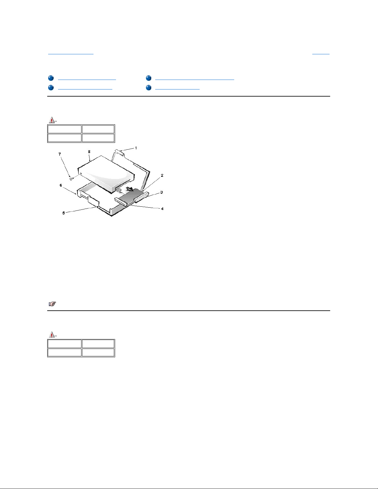
To disassemble the diskette drive, perform the following steps:
1. Remove the diskette drive from the media bay.
2. Remove the two 4-mm screws from the top of the diskette drive assembly.
3. Carefully unsnap the upper plastic from the lower plastic.
The upper plastic is held in place by a series of internal plastic tabs around the edge of the holder.
4. Lift the diskette drive out of the lower plastic.
The metal bracket for the connector may lift out as you remove the diskette drive.
CD-ROM/DVD-ROM Drive Disassembly
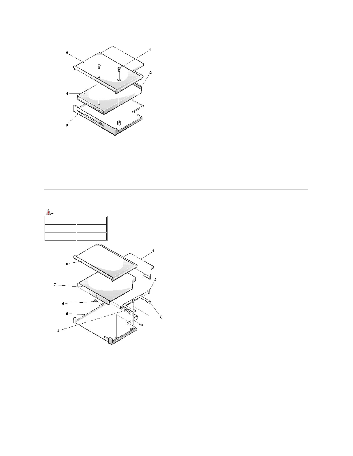
To disassemble the CD-ROM drive or optional DVD-ROM drive, perform the following steps:
1. Remove the CD-ROM drive or the optional DVD-ROM drive from the media bay.
2. Remove the 3-mm screws from both sides of the drive assembly.
3. Insert a flat blade into the slots on the side of the upper plastic and carefully pry the upper plastic away from the lower plastic.
A series of internal plastic tabs holds the plastic in place.
4. Remove two 5-mm screws securing the drive into the lower plastic.
5. Turn the drive assembly over so that the drive falls out of the lower plastic into your hand.
6. Slide the metal plate off of the end of the drive.
7. Remove the 3-mm screw holding the mounting bracket to the drive, and then remove the bracket.
8. Remove (and save for installation) any Kapton tape securing the drive cable.
9. Disconnect the cable.
1
4-mm screws (2)
2
Metal bracket
3
Lower plastic
4
Diskette drive
5
Upper plastic
CAUTION: The following procedure should be performed only by depot repair technicians.
Type of Screw
Torque
FPH 2 x 3 (3)
1.5–1.8 kgf-cm
FPH 2.5 x 5 (2)
2.5–3.0 kgf-cm
1
Metal plate
2
5-mm screws
3
Mounting bracket
4
3-mm mounting bracket screw
5
Lower plastic
6
3-mm drive assembly screws (2)
7
CD-ROM drive or DVD-ROM drive
8
Upper plastic
Page 24

Zip Drive Disassembly
To disassemble the optional Zip drive, perform the following steps:
1. Remove the optional Zip drive from the media bay.
2. Remove the two 5-mm screws from the top of the drive assembly.
3. Carefully unsnap the upper plastic from the lower plastic.
The upper plastic is held in place by a series of internal plastic tabs around the edge of the holder.
4. Lift the Zip drive out of the lower plastic.
The metal bracket for the connector may lift out as you remove the Zip drive.
NOTE: To remove the media from the CD-ROM drive or DVD-ROM drive once the power to the drive is off, insert a small, thin object
(such as one end of a paper clip) into the pinhole near the drive’s LED. This ejects the media tray so that you can retrieve the CD or
DVD.
CAUTION: The following procedure should be performed only by depot repair technicians.
Type of Screw
Torque
FPH 2.5 x 5 (2)
2.5–3.0 kgf-cm
1
5-mm screws (2)
2
Metal bracket
3
Lower plastic
4
Zip drive
5
Upper plastic
NOTE: To remove the media from the Zip drive once the power to the drive is off, insert a small, thin object (such as one end of a paper
clip) into the pinhole in the drive’s LED. This ejects the Zip disk.
Back to Contents Page
Glossary
Page 25

Utilities and Drivers: Dell™ Inspiron™ 3500 Portable Computer
Introduction | Before You Begin | Installing Microsoft Windows 98 and Device Drivers | Installing the Video Driver | Changing Video Resolution | Installing the Audio
Driver | Installing the Internal Modem Driver | Installing the Touch Pad Driver | Installing the DVD/MPEG-2 PC Card, Device Driver, and DVD-to-Go™ Software |
Creating the Save-to-Disk Suspend File | Installing the System User's Guide | Reinstalling Device Drivers
Introduction
You may need to install the Microsoft® Windows® 98 operating system and the Dell™ device drivers and utilities on your Dell Inspiron 3500 portable computer under
the following conditions:
l Dell did not install an operating system or other system software on your computer.
l You are reinstalling the version of Windows 98 that came with your computer, and you need to reinstall the drivers and utilities that Dell provides.
l You have a new hard-disk drive and you need to install all of the system software.
To install the Windows 98 operating system as well as Dell device drivers and utilities, you must have the following items:
l Microsoft Windows 98 CD
l Microsoft Boot Disk Windows 98 Series diskette
l Dell Inspiron 3500 System Software CD
l Diskette drive cable
To install or reinstall Dell utilities and drivers in the Windows 98 operating system, use the program diskette set from Dell or the backup diskettes that you made after
receiving the computer.
Before You Begin
Before you begin the installation, you must install the CD-ROM or the optional DVD-ROM drive in the options bay of your computer, and you must attach the diskette
drive externally. For instructions on installing the CD-ROM or the optional DVD-ROM drive in the options bay, refer to the Dell Inspiron 3500 Portable Computer
— Using the Options Bay document. To install the external diskette drive, perform the following steps:
1. Plug the squared end of the cable into the parallel connector on the back of the computer, and tighten the screws on either side of the cable connector.
2. Plug the triangular end of the cable into the diskette drive, and tighten the screws on either side of the cable connector.
3. Insert the CD-ROM or DVD-ROM drive in the options bay and ensure that the diskette drive is connected to the parallel port connector via the diskette drive
cable.
The diskette drive is now connected.
Installing Microsoft Windows 98 and Device Drivers
To install/reinstall Microsoft Windows 98 and device drivers on your computer, perform the following steps:
1. Insert the Microsoft Boot Disk Windows 98 Series diskette into the external diskette drive.
2. Restart the system.
3. Insert the Microsoft Windows 98 CD into the CD-ROM drive.
4. Ensure that the computer is connected to AC power.
5. When the Microsoft Windows 98 Startup Menu appears, be sure that the 1. Start Windows 98 setup from CD-ROM is highlighted, and press <Enter>.
6. When a message asks you if you want to reinstall Windows 98 over your current operating system, use the down-arrow key to highlight Continue setup and
replace your current operating system, then press <Enter>.
7. When a message tells you that Windows 98 is about to prepare the system for installing the operating system, press <Enter>.
ScanDisk checks your system files.
8. When prompted for the directory in which to install the Windows 98 files, make sure that c:\windows is selected and click Next>.
9. When the Windows 98 Setup window appears, click Continue.
Windows 98 checks your hard-disk drive and prepares your system for installing the operating system.
10. When prompted to quit all programs before continuing the setup, click OK.
The Windows 98 Setup window appears and checks your system for available hard-disk drive space.
11. When prompted to save the existing system files, click Yes (Recommended).
12. When prompted for the drive to which you want to save the system files, click OK to select the default directory or type the path of another directory.
Windows 98 saves the system files to the designated directory.
13. When the Establish Your Location window appears, select your regional location and click Next>.
This setting tells Windows 98 how to display Internet content. If necessary, you can select the keyboard type you want to use.
14. When prompted to create the start-up diskette, remove the boot diskette from the diskette drive and click Next>.
15. Label a blank diskette as instructed, insert the diskette into the diskette drive, and click OK.
If a dialog box instructs you to format the diskette, click Format.
16. After you have created the start-up diskette, remove it from the diskette drive.
17. When the Start copying files window appears, click Next>.
The Welcome to Microsoft Windows 98 window appears and displays information about the operating system while the files are copied to your hard-disk drive.
Page 26

When the files have been copied to the hard-disk drive, Windows 98 prompts you to restart the system.
18. Click OK to restart the computer.
19. In the User Information window, type your name and, if applicable, your company name, then click Next>.
The Name field must be completed. The Company Name is optional.
20. Read the license agreement, click I accept the agreement, and then click Next>.
If you do not accept the agreement, you cannot access Windows 98. After you accept the license agreement, the Product Key window appears.
21. Find the Product Key on the Certificate of Authenticity on the front cover of the Getting Started/Microsoft Windows 98 document, enter the Product Key in
the fields provided, and then click Next>.
22. When the Start Wizard appears, click Finish.
A series of windows appears to inform you that Windows 98 is setting up hardware, initializing drivers, and detecting hardware and Plug and Play devices.
Windows 98 restarts the system and detects additional hardware settings.
The Windows 98 Setup window appears and lists which items Windows 98 is setting up.
Windows 98 updates the system settings and restarts the system.
The Welcome to Windows 98 screen appears.
After installing Windows 98 on your computer, you need to install the following device drivers:
l Video driver
l Internal modem driver
l Audio driver
l Touch pad driver
Installing the Video Driver
The video driver controls features such as screen resolution and the number of screen colors.
To install the video driver, perform the following steps:
1. Insert the Dell Inspiron 3500 System Software CD into the CD-ROM or optional DVD-ROM drive.
2. Click Start, point to Settings, and click Control Panel.
3. In the Control Panel, double-click the Display icon.
4. In the Display Properties screen, click the Settings tab, and then click Advanced.
5. Click the Adapter tab, and then click Change.
6. In the Update Device Driver Wizard screen, click Next>.
7. Click Next> again.
8. Click the Specify a Location checkbox. Uncheck the floppy diskette drive checkbox, and change drive A to D.
9. Click Browse.
10. Double-click the CD-ROM or DVD-ROM icon.
11. Double-click the Video folder.
12. Click OK, and then click Next>.
On the Update Device Driver Wizard screen, the Updated driver (recommended) NeoMagic Magic Media 256AV should be checked.
13. Click Next>.
14. After the driver has been located, click Next>.
15. After Windows has finished installing the updated driver, click Finish.
16. Click Yes to restart the computer.
Changing Video Resolution
To change the video resolution, perform the following steps:
1. When the system restarts, click the Start button, point to Settings, and click Control Panel.
2. Double-click the Display icon and click the Settings tab.
3. Update the Color palette from 256 colors to High Color (16 bit).
4. Set the Screen area to 1024 x 768, and click Apply.
5. Click Apply the new color settings without restarting. Click OK.
6. When a message appears informing you that Windows will resize your computer, click OK.
7. When a message asks if you want to keep the new setting, click Yes.
8. Click Advanced.
9. Click the Monitor tab and click Change.
10. Under models, click Laptop Display Panel (1024 x 768) and click OK.
11. Click Apply and then click OK.
12. Click OK again.
NOTE: This step may take several minutes to complete. The approximate time is displayed on the Windows 98 status bar.
NOTE: If you need to use extended video modes, check the documentation that accompanied the application program to determine if the drivers are
provided. If they are not, contact the software manufacturer to obtain the necessary drivers.
NOTE: After the computer restarts, you may change the video resolution. See the following section, “Changing Video Resolution.”
NOTE: This setting is optimized to DVD.
Page 27

13. Restart the system.
Continue with the installation procedure by installing the audio driver as described in the next section, “Installing the Audio Driver.”
Installing the Audio Driver
The audio driver allows you to customize the sound features of your computer.
To install the audio driver, perform the following steps:
1. Double-click the My Computer icon, and then double-click the CD-ROM or DVD-ROM icon.
2. Double-click the Audio folder.
3. Double-click the setup.exe icon.
4. At the Welcome screen, click Next>.
Messages indicating that files are being copied and driver information is being built appear on your screen.
5. At the NeoMagic License Agreement screen, click Yes.
6. At the Choose Installation Configuration screen, the check boxes for MagicMedia 256AV Audio System and NeoMagic MagicWave 3DX Audio
system are already checked as the defaults. Click Next>.
The audio driver files are copied to the hard-disk drive.
7. At the Setup is Complete window, click Yes, I want to restart my computer now, and click Finish.
Continue with the installation procedure by installing the internal modem driver as described in the next section, “Installing the Internal Modem Driver.”
Installing the Internal Modem Driver
The modem driver allows you to customize the operation of your internal modem. To install the internal modem driver, perform the following steps:
1. Double-click the My Computer icon, and then double-click the CD-ROM or DVD-ROM icon.
2. Double-click the Modem folder.
3. Double-click setup.exe.
4. At the Welcome screen, click Next>.
The internal modem files are copied to your hard-disk drive.
5. At the Setup Complete window, click Finish.
6. After the computer restarts, click the Start button, point to Settings, and click Control Panel.
7. At the Control Panel, double-click the System icon.
8. Click the Device Manager tab. Be sure that View devices by type (default) is selected.
9. In the device list, double-click Other devices, and then click Unknown Device.
10. Click Remove and then click OK at the Confirm Device Removal window.
11. Click Close.
12. Exit the Control Panel window, shut down, and then restart the computer.
Continue with the installation procedure by installing the touch pad driver as described in the next section, “Installing the Touch Pad Driver.”
Installing the Touch Pad Driver
The touch pad driver and associated utilities allow you to customize the operation of your touch pad and cursor features. To install the touch pad driver, perform the
following steps:
1. Double-click the My Computer icon, and then double-click the CD-ROM or DVD-ROM icon.
2. Double-click the Touchpad folder.
3. Double-click the setup.exe icon.
4. At the Welcome screen, click Next>.
5. At the Close Destination Location screen, click Next>.
6. Click Location, then click Next>.
7. At the Start Copying Files window, click Next>.
The touch pad files are copied to your hard-disk drive.
8. At the Setup Complete window, click Yes, I want to restart my computer now, and then click Finish to restart the computer.
Installing the DVD/MPEG-2 PC Card, Device Driver, and DVD-to-Go™Software
Perform the following steps to install the Dell DVD/MPEG-2 PC Card and the required device driver for your computer:
1. Insert the DVD-to-Go CD into the DVD-ROM drive.
2. Insert the MPEG-2 PC Card into the lower of the two connectors in your computer’s PC Card slot.
NOTE: The internal modem is not available in some regions.
Page 28

The first time you insert the MPEG-2 PC Card, the New Hardware Found dialog box appears with the following statement:
DELL-DVD Player
Windows has found new hardware and is locating the software for it.
Then another dialog box appears with the following statement:
Add New Hardware Wizard
This Wizard searches for new drivers for:
Dell-DVD Player
3. Click Next.
A dialog box appears with the following question:
What do you want Windows to do?
4. Click Search for the best driver for your device (Recommended).
5. Click Next.
A dialog box appears with the following statement:
Windows will search for new drivers in its driver database on your hard drive, and in any of the following selected
locations.
6. Click (uncheck) the boxes next to Floppy disk drives and Specify location.
7. Click (check) the box next to CD-ROM drive.
8. Click Next.
A dialog box appears with the following statement:
Windows will search for the driver.
Windows driver file search for the device:
DELL-DVD_Player.
9. Click Next.
The Copying Files dialog box appears with the following message:
The file ‘InstAgnt.exe’ on (Unknown) cannot be found.
10. Click Browse.
11. Click the arrow next to the Drives menu.
12. Select the drive letter (for example, E or G) with the CD icon.
13. Click OK.
14. Click OK again.
The computer automatically installs the DVD device driver onto the hard-disk drive.
After the DVD device driver is installed, your computer emits two beeps notifying you that the MPEG-2 PC Card is recognized.
15. Click Finish.
After the driver software installation has been completed, an installation application for the DVD-to-Go Player software launches automatically.
During the installation, you may need to wait for 6 to 8 seconds between some of the installation windows while the software is being installed from the CD. Do not try to rush
through the installation as you may skip over some important steps. Provide all requested information. For example, be sure to select the appropriate region code.
Creating the Save-to-Disk Suspend File
If you are installing a new hard-disk drive or if you are rebuilding a hard-disk drive with corrupted software and you want to be able to use the save-to-disk suspend
mode, you must use the phdisk.exe utility on the Dell Inspiron 3500 System Software CD to create a save-to-disk suspend file. When save-to-disk suspend mode is
activated, all system data is stored in this file.
To create the save-to-disk suspend file, perform the following steps:
1. Insert the Microsoft Boot Disk Windows 98 Series diskette into the external diskette drive.
2. Restart the system.
3. When the Microsoft Windows 98 Startup Menu appears, select Start computer with CD-ROM Support and press <Enter>.
4. When the MS-DOS® prompt appears, insert the Dell Inspiron 3500 System Software CD into the CD-ROM or optional DVD-ROM drive.
5. At the MS-DOS prompt, type x:, where x is the drive letter for your CD-ROM or DVD-ROM drive, and press <Enter>.
The MS-DOS prompt changes to your CD-ROM or DVD-ROM drive.
6. Type cd\utility and press <Enter>.
7. Type phdisk/create/file and press <Enter>.
The utility calculates the size of the file, in kilobytes, based on the amount of system memory in your computer, plus 2 MB of video memory and additional system requirements.
8. Follow the instructions on your screen to create the save-to-disk suspend file.
To check the size of the save-to-disksuspendfile,typephdisk/info at an MS-DOS prompt and press <Enter>.
If you need to delete the save-to-disksuspendfile,typephdisk/delete/file at an MS-DOS prompt and press <Enter>.
Installing the System User’s Guide
See Documentation to download the Dell Inspiron 3500 System User’s Guide, if needed. Click Dell Inspiron 3500 User's Guide (.hlp) and, when prompted, save
the file to your hard-disk drive.
NOTE: Only the lower PC Card slot connector is designed for use with ZV-capable PC Cards.
NOTE: Your only chance to select the region code occurs during the installation procedure. You cannot change it later. Each region, as defined
in the installation software, encodes DVDs differently. You cannot switch back and forth between differently coded regional DVDs. Once you
choose a region, your PC Card can only play DVDs designed to be sold in that region.
NOTE: Make sure that there is a space between phdisk/create and/file.
Page 29

Reinstalling Device Drivers
If a driver and/or a utility that came with your computer is corrupted, you may wish to reinstall it individually.
The reinstallation procedures for the video driver, the internal modem driver, the audio driver, and the touch pad driver are the same as the installation procedures.
Page 30

External Monitor: Dell™ Inspiron™ 3500 Portable Computer
Use the 15-pin monitor connector to attach an external monitor to the computer. If you reconfigure your hardware, you may need pin number and signal information for
the monitor connector. Use the following procedure to connect an external monitor:
1. Turn off the external monitor and your computer.
Set the monitor on a monitor stand, desktop, or other level surface near the computer.
2. Connect the external monitor's video cable to the computer.
Plug the monitor cable connector into the matching monitor connector at the back of the computer. If the cable is not permanently attached to the monitor, connect it to the monitor
also. Tighten all the screws on the monitor cable connector(s) for proper connection.
3. Connect your external monitor to a grounded electrical outlet.
Plug the three-prong connector on one end of the monitor's power cable into a grounded power strip or some other grounded power source. If the cable is not permanently attached
to the monitor, connect it to the monitor also.
The video image can be displayed on an external monitor, on the computer's display, or on both simultaneously. To toggle between the three display modes, press
<Fn><F8>.
If the external monitor is turned off when you boot the computer, and if the Video Display Device category is set to CRT Mode in the Main menu of the Setup
program, the computer sends the video image to the external monitor. In this case, you do not see an image on either the computer's display or on the external monitor.
To resolve this situation, turn on the external monitor or press <Fn><F8> to switch the video image to the computer's display.
Whether you are using an appropriately equipped multifrequency monitor only or you are using an external monitor and the built-in display simultaneously, you can
display up to 16 million colors at a noninterlaced resolution of 1280 x 1024 pixels.
CAUTION: Do not place the monitor directly on top of your portable computer, even if it is closed. Doing so can crack the computer
case, the display, or both.
NOTE: When the external monitor and built-in display are used simultaneously, the refresh rate is always 60 Hz. Each time you press <Fn><F8>, the
computer switches the video image to the next display in the following sequence: the built-in display, an external monitor, both displays
simultaneously.
Page 31

Exploded View of 13.3-Inch Display Assembly: Dell™ Inspiron™ 3500 Portable Computer
Page 32

Exploded View of 14.1-Inch Display Assembly: Dell™ Inspiron™ 3500 Portable Computer
Page 33

Exploded View of Base Assembly: Dell™ Inspiron™ 3500 Portable Computer
Exploded View of Computer: Dell™ Inspiron™ 3500 Portable Computer
Page 34

Page 35

Exploded View of Palmrest Assembly: Dell™ Inspiron™ 3500 Portable Computer
Page 36

External Keyboard, Keypad, or Mouse: Dell™ Inspiron™ 3500 Portable Computer
You can connect a keyboard with a standard PS/2 connector to the PS/2 connector on the computer, or a USB-compatible keyboard to the USB connector.
You can attach an external numeric keypad to the PS/2 connector on the computer, or a USB-compatible keypad to the USB connector.
You can attach a PS/2-compatible mouse to the PS/2 connector on the computer, or a USB-compatible mouse to the USB connector.
While an external mouse is attached to the computer, the touch pad is still usable.
The touch pad device drivers that Dell installed on your hard-disk drive work with a PS/2 mouse, serial mouse, or USB mouse from Dell. If you did not receive your
mouse from Dell, you must install device drivers separately to use the mouse. This software is usually included with mouse installation kits.
NOTE: You can still use the built-in keyboard when an external keyboard or external keypad is attached to the computer.
NOTE: Before connecting or disconnecting a serial mouse or PS/2 mouse, it is recommended that you turn off your computer.
Page 37

Component Locations (Front View): Dell™ Inspiron™ 3500 Portable Computer
Page 38

Back to Contents Page
Glossary:Dell™Inspiron™3500PortableComputerSystemReference
ABCDEFGHIJKLMNOPQRSTUVWXYZ
To find a term, scroll through the list of terms below or click one of the letter buttons above.
A
A
Abbreviation for ampere(s).
AC
Abbreviation for alternating current.
AC Adapter
An external power supply that converts AC power to DC power for a portable computer. The AC adapter's cable connects to the portable
computer. A power cable connects the AC adapter to an electrical outlet.
active-matrix display
A type of display that uses thin-film transistors. These transistors allow each picture element to be turned on or off.
ADI
Abbreviation for Autodesk Device Interface.
AGP
Abbreviation for accelerated graphics port. AGP is a dedicated graphics port that provides a faster interface between the video subsystem and
the system memory than a PCI graphics device and allows conventional memory to be used for video-related tasks. The improved interface
enables AGP to deliver a smooth, true-color video image.
ANSI
Acronym for American National Standards Institute.
application program
Software, such as a spreadsheet or word processor, designed to help you perform a specific task or series of tasks. Application programs run
from the operating system.
ASCII
Acronym for American Standard Code for Information Interchange.
ASIC
Acronym for application-specific integrated circuit.
ATA
Abbreviation for Advanced Technology Attachment.
attribute
As it relates to DMI, an attribute is a piece of information related to a component. Attributes can be combined to form groups. If an attribute is
defined as read-write, it may be defined by a management application.
autoexec.bat file
The autoexec.bat file is executed when you boot your computer (after executing any commands in the config.sys file). This start-up file contains
commands that define the characteristics of each device connected to your computer, and it finds and executes programs stored in locations other
than the active directory.
Page 39

B
backup
A copy of a program or data file. As a precaution, you should back up your computer's hard-disk drive on a regular basis. Before making a change
to the configuration of your computer, you should back up important start-up files from your operating system.
base memory
Synonym for conventional memory.
batch file
An ASCII text file containing a list of commands that run in sequence. Instead of typing each command, you need only type the batch file name. The
system executes the commands as if you had typed each one individually. Batch files must have a filename extension of bat.
battery
An internal power source used to operate a portable computer. To operate a portable computer on battery power, insert a charged battery into the
main- or optional-battery compartment of the computer.
Battery Performance
Battery performance features such as charge time, operating time, and life span can vary according to the conditions under which the computer
and battery are used.
baud rate
A measurement of data transmission speed. For example, modems are designed to transmit data at one or more specified baud rate(s) through
the COM (serial) port of a computer.
BBS
Abbreviation for bulletin board service. A computer system that serves as a central location for accessing data or relaying messages by modem.
beep code
A diagnostic message in the form of a pattern of beeps from your computer's speaker. For example, one beep followed by two beeps is beep
code 1-2.
binary
A base-2 numbering system that uses 0 and 1 to represent information. The computer performs operations based on the ordering and calculation
of these numbers.
BIOS
Acronym for basic input/output system. Your computer's BIOS contains programs stored on a flash memory chip. The BIOS controls the following:
l Communications between the microprocessor and devices such as the keyboard and the video adapter
l Miscellaneous functions, such as system messages
bit
The smallest unit of information interpreted by your computer.
boot routine
The start-up process of a computer that clears all memory, initializes devices, and loads the operating system.
bootable diskette
A diskette from which you can boot your system. Your Dell Diagnostics Diskette is a bootable diskette.
bpi
Abbreviation for bits per inch.
bps
Abbreviation for bits per second.
Page 40

BTU
Abbreviation for British thermal unit.
bus
An information pathway between the components of a computer. Your computer contains an expansion bus that allows the microprocessor to
communicate with controllers for all the various devices connected to the computer. Your computer also contains an address bus and a data bus
for communications between the microprocessor and RAM.
byte
Eight contiguous bits of information, the basic data unit used by your computer.
BZT
Abbreviation for Bundesamt fur Zulassungen in der Telekommunikation.
C
C
Abbreviation for Celsius.
cache
A fast storage area that keeps a copy of data or instructions for quicker data retrieval. Cache memory enhances the speed of many
microprocessor operations by storing the most-recently accessed contents of system memory.
CardBus
An I/O bus architecture that combines the PCMCIA form factor with 32-bit, 33-MHz PCI bus protocols.
Carnet
A carnet is an international customs document (also known as a merchandise passport) that facilitates temporary imports into foreign countries
and is valid for up to one year.
CD-ROM
Abbreviation for compact disc read-only memory. CD-ROM drives use optical technology to read data from CDs. CDs are read-only storage
devices; you cannot write new data to a CD with standard CD-ROM drives.
CGA
Abbreviation for color graphics adapter.
cm
Abbreviation for centimeter(s).
CMOS
Acronym for complementary metal-oxide semiconductor. In computers, CMOS memory chips are often used for NVRAM storage.
COMn
The device names for the first through fourth serial ports on your computer are COM1, COM2, COM3, and COM4. The default interrupt for COM1
and COM3 is IRQ4, and the default interrupt for COM2 and COM4 is IRQ3. Therefore, you must be careful when configuring software that runs a
serial device so that you don't create an interrupt conflict.
component
As they relate to DMI, manageable components are operating systems, application programs, desktop and server computer systems, adapter
cards, or peripherals that are compatible with DMI. Each component is made up of groups and attributes that are defined as relevant to that
component.
CON
The MS-DOS®device name for the console, which includes your computer's keyboard and text displayed on the screen.
Page 41

config.sys
The config.sys file is executed when you boot your computer (before running any commands in the autoexec.bat file). This start-up file contains
commands that specify which devices to install and which device drivers to use. This file also contains commands that determine how the
operating system uses memory and controls files.
control panel
The part of the computer that contains indicators and controls such as the power button, hard-disk drive access indicator, and reset button.
controller
A chip that controls the transfer of data between the microprocessor and memory or between the microprocessor and a device such as a disk
drive or the keyboard.
conventional memory
The first 640 KB of RAM. Conventional memory is found in all computers.
coprocessor
A chip that relieves the computer's microprocessor of specific processing tasks. A math coprocessor, for example, handles numeric processing. A
graphics coprocessor handles video rendering. The Intel®Pentium®microprocessor includes a built-in math coprocessor.
cpi
Abbreviation for characters per inch.
CPU
Abbreviation for central processing unit. See also microprocessor.
cursor
A marker, such as a block, underscore, or pointer (possibly blinking), that represents the position at which the next keyboard or mouse action will
occur.
D
DAT
Acronym for digital audio tape.
dB
Abbreviation for decibel(s).
DC
Abbreviation for direct current.
Dell Diagnostics
A comprehensive set of diagnostic tests for your Dell computer. To use the diagnostics, you must boot your computer from your Dell Diagnostics
Diskette.
device driver
A program that allows the operating system or some other program to interface correctly with a device such as a printer. Some device drivers,
such as network drivers—must be loaded from the config.sys file (with a device= statement) or as memory-resident programs (usually from the
autoexec.bat file). Others—such as video drivers—must load when you start the program for which they were designed.
DIN
Acronym for Deutsche Industrie Norm.
directory
Directories help keep related files organized on a disk in an ordered, "inverted tree" structure. Each disk has a "root" directory. Additional
directories that branch off of the root directory are called subdirectories. Subdirectories may contain additional directories branching off of them.
Page 42

Disable Autoplay
The autoplay feature in Microsoft® Windows® 98 interferes with the operation of the computer's power management time-outs. If Dell installed
Windows 98 on your hard-disk drive, the autoplay feature was disabled. If you enable autoplay, or if you installed Windows 98 yourself, Dell
recommends that you disable autoplay.
See your Windows 98 documentation for instructions on changing the Auto Insert Notification option.
diskette drive
The diskette drive is a removable-storage device which comes as a combination module with a CD-ROM drive or DVD-ROM drive in the
computer's media bay. The diskette drive lets you install programs and transfer data using 3.5-inch diskettes.
display
See dual-scan display.
display adapter
The logical circuitry that provides—in combination with the display or monitor—your computer's video capabilities. A display adapter may support
more or fewer features than a specific display or monitor offers. Typically, a display adapter comes with video drivers for displaying popular
application programs and operating environments in a variety of video modes. On Dell portable computers, a display adapter is integrated into the
system board.
Display adapters often include memory separate from RAM on the system board. The amount of video memory, along with the adapter's video
drivers, may affect the number of colors or shades of gray that can be simultaneously displayed. Display adapters can also include their own
coprocessor for faster graphics rendering.
DMA
Abbreviation for direct memory access. A DMA channel allows certain types of data transfer between RAM and a device to bypass the
microprocessor.
DMI
Abbreviation for Desktop Management Interface.
DMTF
Abbreviation for Desktop Management Task Force, a consortium of companies representing hardware and software providers, of which Dell
Computer Corporation is a member.
DOC
Abbreviation for Department of Communications (in Canada).
dpi
Abbreviation for dots per inch.
DPMS
Abbreviation for Display Power Management Signaling. A standard developed by VESA® that defines the hardware signals sent by a video
controller to activate power management states in a monitor. A monitor is said to be DPMS-compliant when it is designed to enter a power
management state after receiving the appropriate signal from a computer's video controller.
DRAM
Abbreviation for dynamic random-access memory. A computer's RAM is usually made up entirely of DRAM chips. Because DRAM chips cannot
store an electrical charge indefinitely, your computer continually refreshes each DRAM chip in the computer.
driver
See device driver.
DTE
Abbreviation for data terminal equipment. Any device, such as a computer system, that can send data in digital form by means of a cable or
communications line. The DTE is connected to the cable or communications line through a data communications equipment (DCE) device, such
as a modem.
DVD
Abbreviation for digital versatile disc. A large-capacity optical disc able to store more data than standard CDs.
Page 43

DVD-ROM
Abbreviation for digital versatile disc read-only memory. DVD-ROM drives use optical technology to read data from DVDs. DVDs are read-only
storage devices; you cannot write new data to a DVD with standard DVD-ROM drives. Most DVD-ROM drives also read standard CDs.
E
ECC
Abbreviation for error checking and correction.
ECP
Abbreviation for Extended Capabilities Port. ECP mode, while similar to EPP mode, may provide a performance enhancement to the Microsoft
Windows operating system in that ECP mode can use DMA to transfer data. Also, ECP uses a FIFO buffer for sending or receiving data.
EEPROM
Acronym for electrically erasable programmable read-only memory.
EIDE
Abbreviation for enhanced integrated device electronics. EIDE devices add one or more of the following enhancements to the traditional IDE
standard:
l Data transfer rates of up to 16 MB/sec
l Support for drives other than just hard-disk drives, such as CD-ROM and tape drives
l Support for hard-disk drives with capacities greater than 528 MB
l Support for up to two controllers, each with up to two devices attached
EMI
Abbreviation for electromagnetic interference.
EPP
Abbreviation for Enhanced Parallel Port. A parallel-port design that provides improved bidirectional data transmission.
ESD
Abbreviation for electrostatic discharge.
expansion bus
Your computer contains an expansion bus that allows the microprocessor to communicate with controllers for devices such as a network card or an
internal modem.
expansion card
A printed circuit board that plugs into an expansion-card connector on the computer's system board. An expansion card adds some specialized
function to the computer by providing an interface between the expansion bus and a device. An example of an expansion card is a sound card.
expansion-card connector
A connector on the computer's system board for plugging in an expansion card.
extended memory
RAM above 1 MB. Most software that can use it, such as the Windows 98 operating system, requires that extended memory be under the control
of an XMM.
Extended PC Cards
NOTICE: Take extra precautions if you use extended PC Cards in the computer. Extended cards are longer versions of standard PC
Cards. They fit into, and operate correctly with, the computer. However, they extend beyond the edge of the computer when
installed. If something strikes the exposed end of an installed card, the card or the system board can be damaged. Always remove an
extended PC Card before you pack the computer for traveling.
NOTE: Because of space considerations, you may have trouble using two PC Cards in the computer if one of them is an extended card.
Always install an extended card in the top PC Card connector.
Page 44

F
F
Abbreviation for Fahrenheit.
FAT
Acronym for file allocation table. The file system structure used by the MS-DOS® and Windows operating systems to organize and keep track of
file storage. The Windows NT® operating system can optionally use a FAT file system structure.
FCC
Abbreviation for Federal Communications Commission.
FIFO
Acronym for first-in first-out.
flash memory
A type of EEPROM chip that can be reprogrammed from a utility on diskette while still installed in a computer; most EEPROM chips can only be
rewritten with special programming equipment.
format
To prepare a hard-disk drive or diskette for storing files.
ft
Abbreviation for feet.
FTP
Abbreviation for file transfer protocol.
G
G
Abbreviation for gravities.
GB
Abbreviation for gigabyte(s). A gigabyte equals 1024 MB or 1,073,741,824 bytes.
graphics mode
A video mode that can be defined as x horizontal pixels by y vertical pixels by z colors.
GRMS
Abbreviation for gravity root mean squared.
GST
Abbreviation for Goods and Services Tax.
H
h
Abbreviation for hexadecimal. A base-16 numbering system, often used in programming to identify addresses in the computer's RAM and I/O
memory addresses for devices. The sequence of decimal numbers from 0 through 16, for example, is expressed in hexadecimal notation as: 0, 1,
2, 3, 4, 5, 6, 7, 8, 9, A, B, C, D, E, F, 10. In text, hexadecimal numbers are often followed by h.
heat sink
Page 45

A metal plate with metal pegs or ribs that help dissipate heat. Some microprocessors include a heat sink.
help file
A file containing descriptive or instructional information about a product that is organized and formatted for display by the Windows operating
system. Some help files are associated with a particular program, such as Help in Windows. Other help files, such as this one for your Dell
Dimension system, function as stand-alone reference sources. Help files typically have a filename extension of hlp or chm.
HMA
Abbreviation for high memory area. The first 64 KB of extended memory above 1 MB. A memory manager that conforms to the XMS can make the
HMA a direct extension of conventional memory. See also upper memory area and XMM.
host adapter
A host adapter implements communication between the computer's bus and the controller for a device. (Hard-disk drive controller subsystems
include integrated host adapter circuitry.) To add a SCSI expansion bus to your system, you must install or connect the appropriate host adapter.
HRTF
Acronym for head related transfer function.
Hz
Abbreviation for hertz.
I
I/O
Abbreviation for input/output. The keyboard is an input device, and a printer is an output device. In general, I/O activity can be differentiated from
computational activity. For example, when a program sends a document to the printer, it is engaging in output activity; when the program sorts a list
of terms, it is engaging in computational activity.
ICES
Abbreviation for Interference-Causing Equipment Standard (in Canada).
ICU
Abbreviation for ISA Configuration Utility.
IDE
Abbreviation for integrated drive electronics. See also EIDE.
IrDA
Acronym for Infrared Data Association.
IRQ
Abbreviation for interrupt request. A signal that data is about to be sent to or received by a device travels by an IRQ line to the microprocessor.
Each device connection must be assigned an IRQ number. For example, the first serial port in your computer (COM1) is assigned to IRQ4 by
default. Two devices can share the same IRQ assignment, but you cannot operate both devices simultaneously.
ISA
Acronym for Industry-Standard Architecture. A 16-bit expansion bus design. The expansion-card connectors in an ISA computer are also
compatible with 8-bit ISA expansion cards.
ISP
Abbreviation for Internet service provider. A company that allows you to dial into its host server to connect directly to the Internet.
J
JEIDA
Page 46

Acronym for Japanese Electronic Industry Development Association.
jumper
Jumpers are small blocks on a circuit board with two or more pins emerging from them. Plastic plugs containing a wire fit down over the pins. The
wire connects the pins and creates a circuit. Jumpers provide a simple and reversible method of changing the circuitry in a printed circuit board.
K
K
Abbreviation for kilo-, indicating 1000.
KB
Abbreviation for kilobyte(s), 1024 bytes.
Kb
Abbreviation for kilobit(s), 1024 bits.
KB/sec
Abbreviation for kilobit(s) per second.
Kbps
Abbreviation for kilobyte(s) per second.
key combination
A command requiring you to press multiple keys at the same time. For example, you can minimize all open windows by pressing .
kg
Abbreviation for kilogram(s), 1000 grams.
kHz
Abbreviation for kilohertz, 1000 hertz.
L
LAN
Acronym for local area network. A LAN system is usually confined to the same building or a few nearby buildings, with all equipment linked by
wiring that is dedicated specifically to the LAN.
lb
Abbreviation for pound(s).
LCD
Abbreviation for liquid crystal display. An LCD consists of a liquid crystal solution between two sheets of polarizing material. An electric current
causes each crystal to act like a shutter that can open to allow light past or close to block the light.
LED
Abbreviation for light-emitting diode. An electronic device that lights up when a current is passed through it.
local bus
On a computer with local-bus expansion capability, certain devices such as the AGP video card can be designed to run much faster than they
would with a traditional expansion bus. Some local-bus designs allow devices to run at the same speed and with the same-width data path as the
computer's microprocessor.
logical formatting
Page 47

The method of setting up groups of sectors on a hard-disk drive to store system start-up information, sector status information, and directory
information.
loopback device
A piece of hardware used for testing a serial port or parallel port. The loopback device contains a port connector and sometimes a looped cable.
The connector attaches to the port on the computer and is used during testing to send a signal out through the port and immediately have it
returned through the port.
LPTn
The device names for the first through third parallel ports on your computer are LPT1, LPT2, and LPT3.
LVDS
Acronym for low-voltage differential signaling.
M
m
Abbreviation for meter(s).
mA
Abbreviation for milliampere(s).
math coprocessor
A chip that relieves the computer's microprocessor of numeric-processing tasks. The Intel® Pentium® III microprocessor, for example, includes a
built-in math coprocessor.
Mb
Abbreviation for megabit(s), 1,048,576 bits.
MB
Abbreviation for megabyte(s). The term megabyte means 1,048,576 bytes; however, when referring to hard-disk drive storage, the term is often
rounded to mean 1,000,000 bytes.
MB/sec
Abbreviation for megabytes per second.
Mbps
Abbreviation for megabits per second.
memory
A computer can contain several different forms of memory, such as RAM, ROM, and video memory. Frequently, the word memory is used as a
synonym for RAM; for example, an unqualified statement such as "...a computer with 64 MB of memory" refers to a computer with 64 MB of RAM.
memory address
A specific location, usually expressed as a hexadecimal number, in the computer's RAM.
memory manager
A utility that controls the implementation of memory in addition to conventional memory such as extended memory.
memory module
A small circuit board containing SDRAM chips that connects to the system board.
MHz
Abbreviation for megahertz.
Page 48

microprocessor
The primary computational chip inside the computer that controls the interpretation and execution of arithmetic and logic functions. Software written
for one microprocessor must usually be revised to run on another microprocessor. CPU is a synonym for microprocessor.
MIDI
Acronym for musical instrument digital interface.
mm
Abbreviation for millimeter(s).
modem
A device that allows your computer to communicate with other computers over telephone lines.
mouse
A pointing device that controls the movement of the cursor on a screen. Mouse-aware software allows you to activate commands by clicking a
mouse button while pointing at objects displayed on the screen.
MPEG
Acronym for Moving Picture Experts Group. MPEG is a digital video file format.
ms
Abbreviation for millisecond(s).
MS-DOS
Abbreviation for Microsoft Disk Operating System.
MSN
Abbreviation for the Microsoft Network.
multifrequency monitor
A monitor that supports several video standards. A multifrequency monitor can adjust to the frequency range of the signal from a variety of video
cards.
mV
Abbreviation for millivolt(s).
N
NIC
Abbreviation for network interface controller.
NMI
Abbreviation for nonmaskable interrupt. A device sends an NMI to signal the microprocessor about hardware errors such as a parity error.
ns
Abbreviation for nanosecond(s), one billionth of a second.
NTFS
Abbreviation for the NT File System option in the Windows NT operating system.
NTSC
Abbreviation for National Television Standards Committee. The governing body that dictates broadcast and consumer video guidelines and
values. It ensures that all broadcast, video, and television products in the United States adhere to the NTSC Interface Scan System. NTSC is not
compatible with PAL .
Page 49

NVRAM
Abbreviation for nonvolatile random-access memory. Memory that does not lose its contents when you turn off your computer. NVRAM is used for
maintaining the date, time, and system configuration information.
O
online access service
A service that typically provides access to the Internet, e-mail, bulletin boards, chat rooms, and file libraries.
OTP
Abbreviation for one-time programmable.
P
PAL
Abbreviation for phase alternating line. Standards for television found in many European countries. PAL is not compatible with NTSC, and is not
marketed, sold, or serviced in the United States.
parallel port
An I/O port used most often to connect a parallel printer to your computer. You can usually identify a parallel port on your computer by its 25-hole
connector.
parameter
A value or option that you specify to a program.
partition
A physical storage area on a hard-disk drive that is assigned to one or more logical storage areas known as logical drives. Each partition can
contain multiple logical drives.
After partitioning the hard-disk drive, you must logically format the drive.
See also logical formatting.
PC Card
Slightly larger than a credit card, a PC Card is a removable I/O card, such as a modem, LAN, SRAM, or flash memory card, that adheres to the
PCMCIA standards. PC Cards are sometimes referred to as PCMCIA cards.
PC Card Types
Because a type III card is thicker than type I and type II cards, it takes up the entire PC Card slot, although it uses only one PC Card connector.
PCI
Abbreviation for Peripheral Component Interconnect. A standard for local-bus implementation developed by Intel Corporation.
PCMCIA
Abbreviation for Personal Computer Memory Card International Association.
peripheral device
See device.
PIO
Abbreviation for Programmed I/O.
pixel
A single point on a video display. Pixels are arranged in rows and columns to create an image. A video resolution, such as 800 x 600, is
expressed as the number of pixels across by the number of pixels up and down.
Page 50

Plug and Play
An industry-standard specification that makes it easier to add devices to your personal computer. Plug and Play provides automatic installation
and configuration, compatibility with existing hardware, and dynamic support of mobile computing environments.
POST
Acronym for power-on self-test. Before the operating system loads when you turn on your computer, the POST tests various system components,
such as RAM, the disk drives, and the keyboard.
PS/2
Abbreviation for Personal System/2.
R
RAM
Acronym for random-access memory. The computer's primary temporary storage area for program instructions and data. Each location in RAM is
identified by a number called a memory address. Any information stored in RAM is lost when you turn off your computer.
read-only
A read-only file is one that you are prohibited from editing or deleting. A file can have read-only status if:
l Its read-only attribute is enabled.
l It resides on a physically write-protected diskette or on a diskette in a write-protected drive.
l It is located on a network in a directory to which the system administrator has assigned read-only rights to you.
readme file
A text file included with a software package or hardware product that contains information updating or supplementing the documentation for the
software or hardware. Typically, readme files provide installation information, describe new product enhancements or corrections that have not yet
been documented, and list known problems or other things you need to be aware of as you use the software or hardware.
refresh rate
The rate at which the monitor redraws the video image on the monitor screen. More precisely, the refresh rate is the frequency, measured in Hz, at
which the screen's horizontal lines are recharged (sometimes also referred to as its vertical frequency). The higher the refresh rate, the less video
flicker can be seen by the human eye.
resolution
See video resolution.
RFI
Abbreviation for radio frequency interference.
ROM
Acronym for read-only memory. Your computer contains some programs essential to its operation in ROM code. Unlike RAM, a ROM chip retains
its contents even after you turn off your computer. Examples of code in ROM include the program that initiates your computer's boot routine and the
POST.
rpm
Abbreviation for revolutions per minute.
RTC
Abbreviation for real-time clock. Battery-powered clock circuitry inside the computer that keeps the date and time after you turn off the computer.
S
SCSI
Acronym for small computer system interface. An I/O bus interface with faster data transmission rates than standard ports. You can connect up to
seven devices (15 for some newer SCSI types) to one SCSI interface.
Page 51

SDRAM
Abbreviation for synchronous dynamic random-access memory. SDRAM is a memory technology that improves the performance of your
computer's memory subsystem by reducing the need for wait states. SDRAM devices have a synchronous interface to the devices to which they
are connected and are governed by the system clock. These features reduce the need for wait states often required for conventional memory
devices to ensure that timing signals have been set up correctly.
sec
Abbreviation for second(s).
SECC2
Acronym for single-edge contact cartridge 2. On some systems, the microprocessor is housed in a cartridge that connects to the system board
through an SECC2 connector. The SECC2 connector allows you to upgrade the microprocessor cartridge as future upgrades become available.
serial port
An I/O port used most often to connect a modem to your computer. You can usually identify a serial port on your computer by its 9-pin connector.
service tag
A bar code label on the computer that Dell technicians use to identify your computer when you call Dell for customer or technical support.
setup program
A BIOS-based program that allows you to configure your computer's hardware and customize the computer's operation by setting such features as
password protection. Because the setup program is stored in NVRAM, any settings remain in effect until you change them again.
SGRAM
Acronym for synchronous graphics random-access memory.
shortcut
Icons that provide quick access to frequently used programs, files, folders, and drives. By double-clicking a shortcut, you can open its
corresponding folder or file without having to find it first. Shortcuts do not change the location of files; if you delete a shortcut, the original file is not
affected.
SIMD
Abbreviation for single instruction, multiple data. SIMD is a technology incorporated into certain Intel microprocessors that extends the capabilities
of these microprocessors to handle multimedia and communications software. This technology includes new instructions and data types that
allows the microprocessor to process multiple data elements in parallel, thereby improving overall system performance.
SPD
Abbreviation for serial presence detect.
SRAM
Abbreviation for static random-access memory.
standby mode
A power conservation mode that turns off the display and reduces power to the microprocessor, VGA PCI bus, diskette drive or CD-ROM drive (if
installed), serial and parallel ports, hard-disk drive, PC Card controller, internal speakers and microphone, and external speakers and microphone
(if attached).
SVGA
Abbreviation for super video graphics array. VGA and SVGA are video standards for video cards and controllers with greater resolution and color
display capabilities than previous standards.
To display a program at a specific resolution, you must install the appropriate video drivers and your monitor must support the resolution. Similarly,
the number of colors that a program can display depends on the capabilities of the monitor, the video controller and its drivers, and the amount of
video memory installed in the computer.
SXGA
Abbreviation for super extended graphics array.
system battery
Page 52

A coin-cell battery that maintains system configuration, date, and time information in a special section of memory when the system is turned off.
system board
As the main circuit board, the system board usually contains most of your computer's integral components, such as the following:
l Microprocessor
l RAM
l Controllers for standard devices, such as the keyboard
l Various ROM chips
Frequently used synonyms for system board are motherboard and logic board.
system configuration information
Data stored in memory that tells a computer what hardware is installed and how the computer should be configured for operation.
system diskette
System diskette is a synonym for bootable diskette.
system memory
System memory is a synonym for RAM.
system.ini file
A start-up file for the Windows operating system. When you start Windows, it consults the system.ini file to determine a variety of options for the
Windows operating environment. Among other things, the system.ini file records which video, mouse, and keyboard drivers are installed for
Windows.
Running the Control Panel or Windows Setup program may change options in the system.ini file. On other occasions, you may need to change
or add options to the system.ini file manually with a text editor, such as Notepad.
T
termination
Some devices (such as the last device at each end of a SCSI cable) must be terminated to prevent reflections and spurious signals in the cable.
When such devices are connected in a series, you may need to enable or disable the termination on these devices by changing jumper or switch
settings on the devices or by changing settings in the configuration software for the devices.
text editor
An application program such as Windows Notepad that is used for editing text files. Most word processors use proprietary file formats containing
binary characters, although some can read and write text files.
text mode
A video mode that can be defined as x columns by y rows of characters.
TFT
Abbreviation for thin-film transistor. From one to four of these transistors control each pixel in an active-matrix display for portable computers.
time-out
A time-out is a system setup option that activates a power conservation feature after a specified period of inactivity.
tpi
Abbreviation for tracks per inch.
trackball
A pointing device built in to a portable computer that controls the movement of the cursor on the screen. Trackball-aware software allows you to
activate commands by rolling the trackball and clicking its buttons while pointing at objects displayed on the screen.
touch pad
A pointing device that detects the position of your finger over a touch-sensitive area. It is PS/2 compatible and provides full mouse functionality.
Page 53

TSR
Abbreviation for terminate-and-stay-resident. A TSR program runs "in the background." Most TSR programs implement a predefined key
combination (sometimes referred to as a hot key) that allows you to activate the TSR program's interface while running another program. When you
finish using the TSR program, you can return to the other application program and leave the TSR program resident in memory for later use.
Because MS-DOS® is not designed to support multiple programs running simultaneously, TSR programs can sometimes cause memory conflicts.
When troubleshooting, rule out the possibility of such a conflict by rebooting your computer without starting any TSR programs.
U
UL
Abbreviation for Underwriters Laboratories.
UMB
Abbreviation for upper memory block.
upper memory area
The 384 KB of RAM located between 640 KB and 1 MB. A utility called a memory manager can create UMBs in the upper memory area, in which
you can load device drivers and memory-resident programs.
UPS
Abbreviation for uninterruptible power supply. A battery-powered unit that automatically supplies power to your computer in the event of an
electrical failure.
USB
Abbreviation for Universal Serial Bus. A USB port provides a single connection point for multiple USB-compliant devices such as mice,
keyboards, printers, and computer speakers. USB devices can be connected and disconnected while the system is running.
UXGA
Abbreviation for ultra extended graphics adapter.
V
V
Abbreviation for volt(s).
VAC
Abbreviation for volt(s) alternating current.
VCCI
Abbreviation for Voluntary Control Council for Interference.
VDC
Abbreviation for volt(s) direct current.
VESA
Acronym for Video Electronics Standards Association.
VGA
Abbreviation for video graphics array. VGA and SVGA are video standards for video cards and controllers with greater resolution and color
display capabilities than previous standards.
To display a program at a specific resolution, you must install the appropriate video drivers and your monitor must support the resolution. Similarly,
the number of colors that a program can display depends on the capabilities of the monitor, the video controller and its drivers, and the amount of
video memory installed in the computer.
Page 54

video card
An expansion card that provides the video capabilities—in combination with the monitor—for your computer system. A video card may support
more or fewer features than a specific monitor offers. Typically, a video card comes with video drivers for displaying popular application programs
and operating systems in a variety of video modes.
Video cards can include memory separate from RAM on the system board. The amount of video memory, along with the card's video drivers, may
affect the number of colors that can be simultaneously displayed. Video cards can also include their own coprocessor for faster graphics
rendering.
video driver
A program that allows graphics-mode application programs and operating systems to be displayed at a chosen resolution with the desired
number of colors. A software package may include some "generic" video drivers. Any additional video drivers may need to match the video card
installed in the computer.
video memory
Most VGA and SVGA video cards include memory chips in addition to the computer's RAM. The amount of video memory installed primarily
influences the number of colors that a program can display (with the appropriate video drivers and monitor capabilities).
video mode
Video cards normally support multiple text and graphics display modes. Character-based software, such as text editors, display in text modes that
can be defined as x columns by y rows of characters. Graphics-based software, such as the Windows 98 operating system, displays in graphics
modes that can be defined as x horizontal pixels by y vertical pixels by z colors.
video resolution
Video resolution—800 x 600, for example—is expressed as the number of pixels across by the number of pixels up and down. To display a
program at a specific graphics resolution, you must install the appropriate video drivers and your monitor must support the resolution.
virus
A program designed to be an inconvenience, either by replicating itself until a computer or network runs out of memory or by corrupting files stored
on a hard-disk drive.
The most common way that virus programs move from one computer to another is via "infected" diskettes and from software downloaded from the
Internet. When an infected program is started, so is the embedded virus.
W
W
Abbreviation for watt(s).
wallpaper
The background appearance of the Windows desktop.
WH
Abbreviation for watt-hour(s).
win.ini file
A start-up file for the Windows operating system. When you start Windows, it consults the win.ini file to determine a variety of options for the
Windows operating environment. Among other things, the win.ini file records what printer(s) and fonts are installed for Windows. The win.ini file
also usually includes sections that contain optional settings for Windows application programs that are installed on the hard-disk drive.
Windows 98
An integrated and complete Microsoft Windows operating system that does not require MS-DOS and provides advanced operating system
performance, improved ease of use, enhanced workgroup functionality, and simplified file management and browsing.
Windows NT
High-performance server and workstation operating system software intended for technical, engineering, and financial applications.
write-protected
Read-only files are said to be write-protected. You can write-protect a 3.5-inch diskette by sliding its write-protect tab to the open position or by
Page 55

setting the write-protect feature in the system setup program.
X
XGA
Abbreviation for extended graphics array. VGA, SVGA, and XGA are video standards for video adapters with greater resolution and color display
capabilities than previous standards. XGA generally refers to a video resolution of 1024 x 768 pixels.
To display a program at a specific resolution, you must install the appropriate video drivers and your display and/or external monitor must support
the resolution. Similarly, the number of colors that a program can display depends on the capabilities of the display and/or monitor, the video
driver, and the amount of video memory installed in the computer.
XMM
Abbreviation for extended memory manager, a utility that allows applications and operating systems to use extended memory in accordance with
the XMS.
XMS
Abbreviation for eXtended Memory Specification.
Z
ZV Port
Abbreviation for Zoom Video port. A port to the video controller that provides hardware MPEG-1 decode (and encode) solutions in notebooks.
These solutions could include PC Card (CardBus), or on-board solutions. ZV Port must be integrated into notebook board design to allow for
these solutions to be passed directly through to the video processor, circumventing the processor, allowing for more efficient CPU utilization.
Windows NT does not support Zoom Video.
Back to Contents Page
Page 56

Graphics: Dell™ Inspiron™ 3500 Portable Computer
Status Display
Component Locations (Front View)
Component Locations (Back View)
AC Adapter
Removing and Installing a Battery
Battery Charge Gauge
Removing Devices From the Options Bay
Removing the Hard-Disk Drive
Removing a Memory Module
Touch Pad
Audio Jacks
PC Card Slots
Embedded Numeric Keypad
Security Cable Slot
I/O Connectors
30°ConeofInfraredLight
Page 57

I/O Connectors: Dell™ Inspiron™ 3500 Portable Computer
Page 58

I/O: Dell™ Inspiron™ 3500 Portable Computer
Infrared Port | USB Connector | Serial Connector | Parallel Connector | Monitor Connector | PS/2 Connector
I/O Connectors
Infrared Port
The computer comes with an infrared port. An infrared data stream is transmitted through a lens in the computer, up to a distance of 1 m, and received by a compatible
computer, printer, mouse, or remote control.
The infrared port lets you transfer files from the computer to another infrared device, without using cable connections. You can also use other commercially available
infrared-capable application programs.
To use the infrared port, point the computer’s infrared port directly at the infrared port of the compatible device. Infrared devices transmit data in a 30°coneofinfrared
light. Start the data communications software on both devices, and then begin transferring files. Read the documentation that came with your compatible device to make
sure you operate it correctly.
For information on configuring the standard infrared drivers that came with Windows 98, see your operating system documentation.
USB Connector
Use the USB connector to attach up to two USB devices, such as a mouse, to the computer. USB is a peripheral bus standard that enables automatic detection of
USB-compliant peripheral devices.
Pin Assignments for the USB Connector
Serial Connector
Use the 9-pin serial connector to attach a serial device to the computer. The serial port passes data in serial format (one bit at a time over one line). This port supports
a variety of devices, including a serial mouse, that require serial data transmission. If you reconfigure your hardware, you may need pin number and signal information
for the serial connector.
Pin Assignments for the Serial Connector
NOTE: Make sure that there are no books, papers, or other objects between the two infrared devices and that the two devices are within the 30° cone.
Pin
Signal
Definition
1
VCC
Cable power
2
-Data
N/A3+Data
N/A4Ground
Cable ground
Pin
Signal
I/O
Definition
1
DCDIData carrier detect
2
RXDAIReceive data
3
TXDAOTransmit data
Page 59

Parallel Connector
Use the 25-hole parallel connector to attach a parallel device to the computer. The parallel connector is used primarily for printers. The parallel port sends and receives
data in parallel format, where eight data bits (one byte) are sent simultaneously over eight separate lines.
The parallel port can also be configured for compatibility with the PS/2 standard. Support for the EPP feature improves network adapter performance (adapters
connect to the computer's parallel port and require the appropriate software drivers from the adapter's manufacturer).
If you reconfigure your hardware, you may need pin number and signal information for the serial connector.
Pin Assignments for the Parallel Connector
Monitor Connector
Use the 15-pin monitor connector to attach an external monitor to the computer.
Pin Assignments for the Monitor Connector
4
DTROData terminal ready
5
GND
N/A
Signal ground
6
DSRIData set ready
7
RTSORequest to send
8
CTSIClear to send
9RII
Ring indicator
Shell
N/A
N/A
Frame ground
Pin
Signal
I/O
Definition
1
STB#
I/O
Strobe2PD0
I/O
Parallel data bit 0
3
PD1
I/O
Parallel data bit 1
4
PD2
I/O
Parallel data bit 2
5
PD3
I/O
Parallel data bit 3
6
PD4
I/O
Parallel data bit 4
7
PD5
I/O
Parallel data bit 5
8
PD6
I/O
Parallel data bit 6
9
PD7
I/O
Parallel data bit 7
10
ACK#IAcknowledge
11
BUSYIBusy12PEIPaper end
13
SLCTISelect14AFD#OAutomatic feed
15
ERR#IError16INIT#OInitialize printer
17
SLIN#OSelect in
18–25
N/A
N/A
Signal ground
Shell
N/A
N/A
Frame ground
Page 60

PS/2 Connector
Use the 6-hole, miniature DIN PS/2 connector to attach PS/2-compatible devices such as a mouse, keyboard, or external numeric keypad.
Pin Assignments for the PS/2 Connector
Pin
Signal
I/O
Definition
1
REDORed video
2
GREEN
O
Green video
3
BLUEOBlue video
4NCN/A
No connection
5
GND
N/A
Signal ground
6
GND
N/A
Signal ground
7
GND
N/A
Signal ground
8
GND
N/A
Signal ground
9NCN/A
No connection
10
GND
N/A
Signal ground
11NCN/A
No connection
12NCN/A
Reserved
13
HSYNC
O
Horizontal synchronization
14
VSYNC
O
Vertical synchronization
15NCN/A
No connection
Shell
N/A
N/A
Frame ground
Pin
Signal
I/O
Definition
1
EXK_MSDATA
I/O
External keyboard/keypad/mouse data
2NCN/A
No connection
3
GND
N/A
Signal ground
4
EXK_MSPWR
O
External keyboard/keypad/mouse supply voltage
5
EXK_MSCLK
I/O
External keyboard/keypad/mouse clock
6NCN/A
No connection
Shell
N/A
N/A
Frame ground
Page 61

30°ConeofInfraredLight:Dell™ Inspiron™ 3500 Portable Computer
Page 62

Jumpers,Switches,Controls,andIndicators:Dell™Inspiron™3500PortableComputer
System Reference
Jumpers
There are no jumpers on this system.
Switches
There are no configuration switches on this system.
Controls and Indicators
Back to Contents Page
Glossary
Jumpers
Switches
Controls and Indicators
1
LCD latch
2
Status lights (next to LCD latch)
3
Display
4
PC Card connectors (2)
5
Audio jacks (3)
6
AC adapter connector
7
Speaker
8
Battery release latch
9
Battery bay
10
Media bay
11
Touch pad buttons (2)
12
Touch pad
13
Keyboard
Page 63

Status Lights
Three status lights are located on the connector cover directly above the keyboard:
l Caps Lock: Solid green light when Caps Lock is on. Press <Caps Lock> to turn this feature on or off.
l Scroll Lock: Solid green light when Scroll Lock is on. Press <Scroll Lock> to turn this feature on or off.
l Num Lock: Solid green light when Num Lock is on. Press <Num Lock> to turn this feature on or off.
Three additional status lights are located on the front of the unit, to the right of the LCD latch:
l System power:
¡ No light when the system is off or in suspend-to-disk mode (hibernating)
¡ Green light when the system is on
¡ Amber light when the system is in standby or suspend-to-RAM mode
l Hard-disk drive activity: Blinking light as the hard-disk drive or a PC Card is being accessed
l Battery status:
¡ Blinking green light when the AC adapter is attached and the battery is charging
¡ Green light when the AC adapter is attached and the battery is fully charged. A green light also indicates a battery problem (such as a
bad cell, overheating, or overcharging). Use the battery charge gauge to further determine the battery status.
Some devices located in the media bay (diskette drive, CD-ROM drive, DVD-ROM drive, Zip drive) also have an activity light indicating when the
device is being accessed.
Battery Charge Gauge
14
Power button
15
Connector cover
16
Microphone
17
Display close/suspend button
18
Status lights (3) (on keyboard)
1
Caps Lock status
2
Scroll Lock status
3
Num Lock status
1
System power status
2
Hard-disk drive activity status
3
Battery status
1
Battery tester
2
Status lights (5)
Page 64

The battery charge gauge on the bottom of the battery has five status lights that indicate how much battery charge remains. Each light indicates
approximately 20% battery charge. Press the battery tester (a textured square on the back of the battery) to check the total battery charge.
Power Button
Under normal circumstances, you should only use the power button to turn on the computer or to resume operation from save-to-disksuspend
mode. To shut down the computer, click the Start button in the Microsoft® Windows® 98 operating system, and then click Shut Down. If the
computer is "locked up"—that is, it does not respond to commands—press and hold down the power button for at least five seconds.
Display Close Button
When you close the display, this button activates Standby mode. Do not press this button.
Back to Contents Page
Glossary
Page 65

Embedded Numeric Keypad: Dell™ Inspiron™ 3500 Portable Computer
Page 66

Memory: Dell™ Inspiron™ 3500 Portable Computer
Memory Installation Guidelines | Valid Memory Configurations | Removing and Installing Memory | Upper Memory Map | Conventional Memory Map
Memory Installation Guidelines
l The system can accommodate up to 256 MB of RAM.
l The system comes with a minimum of 32 MB of memory.
l To increase memory, install 32-, 64-, or 128-MB memory modules.
Valid Memory Configurations
Removing and Installing Memory
To remove or install memory, perform the following steps:
1. Save and close any open files, and exit all application programs.
2. Shut down your computer.
3. Turn off all peripherals and disconnect them from the computer. If you are using the AC adapter, detach it as well.
4. Remove any installed batteries.
5. Ground yourself by touching the unpainted metal surface of the I/O panel on the back of the computer.
While you work, periodically touch the I/O panel to dissipate any static electricity that might harm internal components.
6. Turn the computer over, and remove the memory module cover.
Remove the two screws from the memory module cover. Use your finger or a flat plastic tool to lift the cover out.
7. If you are replacing a memory module, remove the existing memory module(s).
Carefully spread apart the inner plastic tabs of the memory module socket to disengage the module from the socket. The module pops up slightly. Gently pull the memory module out
of the socket.
8. Install the new memory module.
Align the notch in the edge connector with the slot in the center of the memory module socket. Press the memory module’s edge connector firmly into the socket, and push the
module down until it clicks.
9. Replace the memory module cover, and replace the two screws.
10. Reinstall any batteries you removed in step 4. Reconnect the peripherals to the computer. Turn on the peripherals and then turn on the computer. If you were
using the AC adapter, reattach it as well.
As the computer boots, it detects the additional memory and automatically updates the system configuration information.
11. Confirm that the system configuration information reflects the newly installed memory by checking the System Memory option on the Main menu of the Setup
program.
To enter the Setup program, press <F2> while the computer is booting. The Main menu appears. If the System Memory total is incorrect, the memory modules may not be installed
properly. Repeat steps 1 through 10 until the memory total is correct.
12. Run the RAM test group in the Dell Diagnostics to confirm that the installed memory modules are operating correctly.
For instructions on running the RAM test group in the Dell Diagnostics, see Chapter 4, "Running the Dell Diagnostics," in your Reference and Troubleshooting Guide.
Base
Install
Total
32 MB
32 MB
64 MB
32 MB
64 MB
96 MB
32 MB
128 MB
160 MB
64 MB
32 MB
96 MB
64 MB
64 MB
128 MB
64 MB
128 MB
192 MB
128 MB
32 MB
160 MB
128 MB
64 MB
192 MB
128 MB
128 MB
256 MB
CAUTION: Ground yourself by attaching an antistatic grounding strap to your wrist and to an unpainted metal surface on the computer’s I/O
panel. If an antistatic grounding strap is not available, periodically discharge static electricity from your body by touching one of the connectors
on the I/O panel.
CAUTION: Do not install or remove a memory module when the computer is turned on or in save-to-disk suspend mode.
CAUTION: To prevent damage to the computer, do not use tools to spread the inner plastic tabs of the socket when you are installing or
removing a memory module.
NOTE: If one memory module is already installed and you are adding a second memory module, put the second module in the available slot.
Remove an existing module only if you are replacing it. Depending on how you ordered your computer, one or two modules may already be
installed.
Page 67

13. If you have added additional memory to your computer, you need to delete and re-create the save-to-disk suspend file on your hard-disk drive so that it is large
enough to accommodate the new memory. For instructions, see the topic titled "Save-to-Disk Suspend File" in your online System User’s Guide.
Upper Memory Map
Conventional Memory Map
Location
Description
10FFF0
Extended memory
100000–10FFEF
High memory area
0F0000–0FFFFF
System BIOS
0E0000–0EFFFF
Video BIOS
0DC000–0DFFFF
Available
0D0000–0DBFFF
PC Card memory
0C0000–0CFFFF
Available
0A0000–0BFFFF
Video RAM
09FC00–09FFFF
PS/2 mouse-data area
000000–09FBFF
Conventional memory
Segment
Address Range
Use000000h–003FFh
Interrupt vector table
00400h–004FFh
BIOS data area
00500h–005FFh
MS-DOS® work area
00600h–0FFFFh
User memory
1
10000h–1FFFFh
User memory
2
20000h–2FFFFh
User memory
3
30000h–3FFFFh
User memory
4
40000h–4FFFFh
User memory
5
50000h–5FFFFh
User memory
6
60000h–6FFFFh
User memory
7
70000h–7FFFFh
User memory
8
80000h–8FFFFh
User memory
9
90000h–9FBFFh
User memory
9FC00h–9FFFFh
PS/2 mouse-data area
Page 68

Tech Notes: Dell™ Inspiron™ 3500 Portable Computer
Video
I/O
Memory
Power Sources
Storage Devices
Touch Pad
Audio
PC Cards
Embedded Numeric Keypad
External Monitor
External Keyboard, Keypad, or Mouse
Power Management
Passwords and Security
Setup Program
Utilities and Drivers
Removing and Replacing Parts
Page 69

Embedded Numeric Keypad: Dell™ Inspiron™ 3500 Portable Computer
The embedded numeric keypad shares some of the keys on your computer's keyboard. The keypad numbers and symbols are marked on the right of the keypad keys.
To activate the embedded numeric keypad, press <Num Lock> (the Num Lock LED lights up). Press and hold <Fn> to toggle between the letter and number keys.
To deactivate the keypad, press <Num Lock>. The Num Lock LED is no longer illuminated.
Key combinations can be used when the keypad is off or on.
When Key Pad Is On
Purpose
<Num Lock>
Toggles the embedded numeric keypad between number and letter keys
<Fn><key>
Temporarily disables the embedded numeric keypad; enables the
lowercase characters/functions of the keyboard
<Fn><Shift><key>
Temporarily disables the embedded numeric keypad; enables the
uppercase characters/functions of the keyboard
<Shift><cursor key>
Temporarily enables a cursor-control key in the embedded numeric
keypad
Page 70

PalmrestAssembly:Dell™Inspiron™3500PortableComputerSystemReference
Exploded View of Palmrest Assembly
Palmrest Assembly Removal
Back to Contents Page
Glossary
Exploded View of Palmrest Assembly
Palmrest Assembly Removal
Touch Pad Assembly Removal
1
Connector cover
2
Keyboard
3
Palmrest
4
Touch pad
5
Touch pad assembly
6
Touch-pad FPC cable
7
5-mm screws (3)
8
System-board retaining clip with 14-mm screw
9
Bottom plastic
10
Optional internal modem with 14-mm screw
Type of Screw
Torque
FPH 2.5 x 19 (7)
3.5–4.0 kgf-cm
Page 71

To remove the palmrest assembly, see the exploded view of the palmrest assembly and perform the following steps:
1. Remove the display assembly.
2. Remove the keyboard.
3. Turn the computer face down.
4. Remove the seven 19-mm palmrest screws from the bottom of the computer.
5. Turn the computer face up.
6. Remove the palmrest assembly.
After installing the palmrest assembly, make sure that the battery-bay release latch and the options-bay release latch operate smoothly. If they do
not, slightly loosen the two palmrest assembly screws that secure the latches so that the latches move easily.
Touch Pad Assembly Removal
To remove the touch pad assembly, see the exploded view of the palmrest assembly and perform the following steps:
1. Remove the display assembly.
2. Remove the keyboard.
3. Remove the palmrest assembly.
4. Remove the three 5-mm screws securing the touch pad assembly to the palmrest assembly.
5. Lift the touch pad assembly out of the palmrest assembly.
6. Disconnect the touch-pad FPC cable from the center-lift ZIF connector J1 on the touch pad.
The touch pad buttons are heat-staked into the touch pad assembly and cannot be removed.
1
16-mm screws (7)
Type of Screw
Torque
FPH 2.5 x 5 (3)
3.0–3.5 kgf-cm
Back to Contents Page
Glossary
Page 72

Passwords and Security: Dell™ Inspiron™ 3500 Portable Computer
About Passwords | Physically Securing the Computer | Disabling the Serial, Infrared, and Parallel Ports
About Passwords
When you receive the computer, the password features are disabled so that you can assign passwords if you wish. Once you assign a password, you must enter the
password to access the Setup program.
Use the Security menu in the Setup program to assign a password.
Physically Securing the Computer
To prevent unauthorized removal of the computer, use a security cable to attach the computer to an immovable object.
The security cable slot lets you attach a commercially available antitheft device to the computer. Antitheft devices for portable computers usually include a segment of
metal-stranded cable with an attached locking device and associated key. Complete instructions for installing this kind of antitheft device are usually included with the
device.
To prevent unauthorized removal of the computer, loop the cable around an immovable object, insert the locking device into the security cable slot, and lock the
device.
Disabling the Serial, Infrared, and Parallel Ports
You can disable the serial port to prevent unauthorized access to the computer through an external serial device. To disable the serial port, set the Serial Port option to
Off in the System Devices menu of the Setup program. In addition, you should set up a password in the Security menu of the Setup program.
You can disable the infrared port to prevent unauthorized access to the computer through an external infrared device. To disable the infrared port, set the IR Port
option to Off in the System Devices menu of the Setup program.
You can disable the parallel port to prevent unauthorized access to the computer through an external parallel device. To disable the parallel port, set the Parallel Port
option to Off in the System Devices menu of the Setup program.
Disabling any of these ports also prevents the unauthorized download of data from that port.
CAUTION: The password features provide a high level of security for the data in the computer. However, they are not foolproof. If your data
requires more security, it is your responsibility to obtain and use additional forms of protection, such as data encryption programs or PC Cards
with encryption features.
NOTE: Antitheft devices are of differing designs. Before purchasing such a device, make sure it will work with the security cable slot in the computer.
Page 73

PC Cards: Dell™ Inspiron™ 3500 Portable Computer
About PC Cards | Installing PC Cards | Removing PC Cards | Configuring PC Cards
About PC Cards
You can install up to two PC Cards that adhere to PCMCIA standards and release 4.2 of the JEIDA standard.
The computer supports type I, type II, and type III PC Cards, including such memory devices as SRAM cards that emulate diskettes, RAM cards, OTP ROM cards,
and ATA cards that emulate IDE hard-disk drives. The computer also can support I/O cards such as modem communication cards, LAN cards, wireless LAN cards,
SCSI cards, and sound cards.
You can install one type III or two type I or type II cards in the computer. You can also use extended PC Cards in the computer.
Both PC Card slots support CardBus technology. In addition, a ZV Port is available from the lower slot (slot 0). If you ordered an MPEG -2 decoder PC Card from
Dell, install it in the lower PC slot.
Installing PC Cards
The PC Card slot has two PC Card connectors and supports four combinations of cards:
l A single type I or type II card (using either the top or bottom PC Card connector)
l One type I card and one type II card (using either connector)
l Two type I cards or two type II cards
l One type III card (using the bottom connector)
The type of card refers to its thickness, not its functionality. Because a type III card is thicker than type I and type II cards, it takes up the entire PC Card slot, although
it uses only one PC Card connector.
PC Cards are generally marked with a symbol (such as a triangle or an arrow) to indicate which end should be inserted into the slot. The cards are keyed to prevent
incorrect insertion. If card orientation is not clear, see the documentation that came with the card.
You can install a PC Card while the computer is running. The PC Card is automatically detected.
Unpack the card and install it by performing the following steps:
1. If necessary, remove the blank from the connector you intend to use.
2. Hold the card with its orientation symbol pointing into the slot and the top side of the card facing up.
3. Insert the card into the slot and press in firmly until the card is completely seated in the internal PC Card connector.
If there is too much resistance when inserting the card, do not force the card. Check the card's orientation, and try again.
The computer recognizes most I/O cards and automatically loads the appropriate device driver.
If you have older modem communications software that cannot use certain IRQ settings, you must disable the serial port or infrared port to use the software.
Removing PC Cards
To remove a PC Card, use your finger tip to flip the eject button out so that it is perpendicular to the computer. Push in the eject button to release the card. Gently
CAUTION: Take extra precautions if you use extended PC Cards in the computer. Extended cards are longer versions of standard PC Cards.
They fit into, and operate correctly with, the computer. However, they extend beyond the edge of the computer when installed. If something
strikes the exposed end of an installed card, the card or the system board can be damaged. Always remove an extended PC Card before you pack
the computer for traveling.
NOTE: Because of space considerations, you may have trouble using two PC Cards in the computer if one of them is an extended card. Always install
an extended card in the top PC Card connector.
NOTES: A PC Card is not a boot device.
"Type of card" refers to its thickness, not its functionality.
NOTE: It is important that you complete the setup of your operating system before installing a PC Card.
NOTES: If you ejected a blank or another PC Card before you inserted the PC Card, the eject button slides out when you insert the new card. To
repositiontheejectbutton,useyourfingertiptoflipthebuttontowardthefrontofthecomputeruntilthebuttonisflushwiththecomputercasing.
If the PC Card connector was empty when you inserted a PC Card, the eject button remains flush with the computer casing during and after
insertion.
Page 74

remove the PC Card.
After you have removed a PC Card or PC Cards, you should install one or both of the PC Card blanks provided with the computer to protect the PC Card
connectors.
See Installing Utilities and Drivers for information on installing or reinstalling PC Card utilities and drivers.
Configuring PC Cards
If you are using the Microsoft® Windows® 98 operating system, click the Start button, point to Settings, and then click Control Panel. Double-click the PC Card
icon to open the PC Card Properties window. For more information, check the documentation that came with your operating system.
You can also double-click the PC Card icon on the Windows 98 desktop.
Page 75

PC Card Slots: Dell™ Inspiron™ 3500 Portable Computer
Page 76

Power Sources: Dell™ Inspiron™ 3500 Portable Computer
AC Adapter | Battery | Removing and Installing the Main Battery | Removing and Installing a Second Battery | Charging the Battery | Checking a Battery’s Charge
Level
AC Adapter
The AC adapter converts AC power to the DC power required by the computer. The AC adapter kit includes two cables: the AC adapter cable and an AC power
cable.
You can connect the AC adapter with your computer either turned on or off.
The AC adapter works with AC power sources worldwide. However, power connectors vary among countries. Before using AC power in a foreign country, you may
need to obtain a new power cable designed for use in that country.
If you are running your computer on AC power with a battery installed, the AC adapter charges the battery (if needed) and then maintains its charge.
When your computer is turned on, the green power indicator light is constantly lit, which indicates that the system is active. This light is on when the computer is running
either from AC or battery power. If the light is amber-colored, the computer is in Standby mode.
The battery charge indicator LED shows the status of the battery. When the AC adapter is connected to the computer, this light is green. When the battery is charging,
this light blinks slowly. When this light stops blinking and becomes solid green, the battery is fully charged.
Battery
The battery uses lithium ion technology to power the computer when it is not connected to an AC power source. The main battery comes standard with the computer.
To double battery life, you can install an optional second battery in the options bay.
You can expect 2 to 3 hours of battery life with a single fully charged battery and 4 to 6 hours of battery life with two fully charged batteries. A built-in charge gauge
lets you check a battery's charge before you insert it into the computer. The battery's self-test capability alerts you to battery conditions such as low charge.
A number of factors affect battery operating time:
l The power conservation features used
l The number and type of PC Cards used
l The kinds of application programs run
l The capacity of the optional memory module installed (the higher the capacity, the more power used)
l The use of an internal Zip drive, CD-ROM drive, or DVD-ROM drive, which use more power than a hard-disk drive or a diskette drive
See also Power Conservation.
Removing and Installing the Main Battery
To remove and install the main battery, perform the following steps:
1. Save any files you have open and exit all application programs.
2. If your computer is operating on battery power, preserve your data by connecting the AC adapter and plugging it into an electrical outlet or by shutting down
yourcomputerfromtheStartmenu.
3. Remove the main battery.
Using your index finger, pull the battery bay latch (located on the side of the computer next to the battery bay) toward you. With your thumb, gently push the latch out and back
until the battery pops out. Grasp the battery firmly and slide it out of the battery bay.
4. Install the new battery.
With the battery bay latch released, slide the new battery into the battery bay until it is flush with the computer casing. You cannot fully insert the battery into the computer unless
the battery bay latch is released. Close the battery bay latch by using your index finger to push it toward the front of the computer until it is flush with the computer casing. Using
your thumb, push the battery bay latch in.
5. Turn on the computer.
CAUTION: The AC adapter should be in a ventilated area, such as on a desktop or on the floor, when used to power the computer or charge the
battery. Do not use the AC adapter in a poorly ventilated environment, such as inside a carrying case.
CAUTION: The AC adapter is designed to work only with Dell Inspiron portable computers. Do not use adapters from other computers, and do
not attempt to use this adapter with other computers.
CAUTION: The battery is designed to work with Dell Inspiron 3500 series computers only. Do not use the battery with other computers, and do
not use batteries from other computers in your computer.
Page 77

Removing and Installing a Second Battery
To remove and install the second battery, perform the following steps:
1. Save any files you have open and exit all application programs.
2. If your computer is operating on battery power, preserve your data by connecting the AC adapter and plugging it into an electrical outlet or by shutting down
yourcomputerfromtheStartmenu.
3. Remove the main battery.
Using your index finger, pull the options bay latch (located on the side of the computer next to the options bay) toward you. With your thumb, gently push the latch out and back
until the battery pops out. Grasp the battery firmly and slide it out of the options bay.
4. Install the new battery.
With the options bay latch released, slide the new battery into the options bay until it is flush with the computer casing. You cannot fully insert the battery into the computer unless
the options bay latch is released. Close the options bay latch by using your index finger to push it toward the front of the computer until it is flush with the computer casing. Using
your thumb, push the options bay latch in.
5. Turn on the computer.
Charging the Battery
Each time you connect the computer to AC power or install a battery in a computer that is connected to AC power, the computer checks the battery's charge and
temperature. The AC adapter then charges the battery (if necessary) and maintains the battery's charge.
If two batteries are installed in the computer, the AC adapter charges the battery in the battery bay first, and then charges the second battery in the options bay. (The
second battery is discharged first.)
The battery LED, located to the right of the display latch, appears as a blinking green light while the battery is charging.
The AC adapter needs from 2 to 3 hours (depending on whether the system is on or off) to fully charge a battery that has been completely discharged.
Checking a Battery's Charge Level
Use one of the following methods to check the battery's charge level:
l Check the battery charge level before you insert the battery into your computer. Once the battery is inserted into the computer, you cannot see the charge gauge.
The battery has a charge gauge with five charge-level indicator lights that show how much battery charge remains. Press the battery tester (a textured square on
the back of the battery) to check the charge level. Each light represents approximately 20% of the total battery charge. For example, if the battery has 80% of its
charge remaining, four of the lights come on during testing. If none of the lights come on when you press the battery tester, the battery has no charge left.
l A low-battery warning occurs when the battery is about 90% depleted. The speaker beeps once every 15 seconds. When you hear the low-battery warning,
only a few minutes of battery life remain. If both the main battery and the second battery are installed, the low-battery warning means that the combined charge
of both batteries is about 90 percent depleted.
l If you are using the Microsoft
®
Windows® 98 operating system, click the Start button, point to Settings, and then click Control Panel. Double-click the
Power Management icon to open the Power Management Properties window. For more information, check the documentation that came with your
operating system.
l The Windows 98 battery meter displays a battery icon that shows the amount of battery charge remaining. If an AC adapter is connected to the computer, the
battery meter displays a plug icon. The battery meter icons are visible in the desktop taskbar. If you move the cursor over the battery or plug icon in the desktop
taskbar, a pop-up window shows the battery's current charge status percentage.
NOTE: You can leave the battery in the computer as long as you like. The battery's built-in circuitry prevents the battery from overcharging.
CAUTION: If only one or none of the charge-level indicator lights are lit, it indicates a critically low battery state. Do not use the
battery unless the computer is connected to AC power or unless you install a second charged battery.
CAUTION: To avoid losing data (and possibly corrupting data areas on your hard-disk drive), save your work immediately after a
low-battery warning. Then connect the computer to AC power, or install a second battery in the options bay. If the battery runs
completely out of power, the computer activates save-to-disk suspend mode.
Page 78

Power Management: Dell™ Inspiron™ 3500 Portable Computer
How to Conserve Battery Power | Using Microsoft® Windows® 98 to Conserve Battery Power | Experimenting with Power Conservation | Checking the Battery
Status | Standby Mode | Turn Off Monitor | Turn Off Hard-Disk Drive | Save-to-Disk Suspend Mode | Save-to-Disk Suspend File
How to Conserve Battery Power
You automatically conserve battery power each time you attach an AC power source to the computer. When the AC adapter is attached, the battery or batteries, if
installed, are being charged while the computer runs from AC power. The life expectancy of your battery is determined largely by the number of charges it receives, so
use an AC power source to run the computer if one is available.
Use the Windows 98 Power Management Properties window to adjust the way the computer uses battery power. Options in the window slow or stop some
internal devices when the computer is idle.
Take advantage of the computer's power management modes, set in the Windows 98 Power Management Properties window, when you leave the computer
unattended for long periods of time. Standby, Turn Off Monitor, and Turn Off Hard Drive allow you to maximize power conservation when your work is
interrupted.
When the computer is using battery power, remove PC Cards that you are not using.
Experiment with power conservation features to achieve the optimum power conservation for your work environment.
Using Microsoft® Windows® 98 to Conserve Battery Power
Complete the following steps in Windows 98 to access the Power Management Properties window and set the power management features:
1. Click the Start button, point to Settings, and click Control Panel.
2. Double-click the Power Management Properties icon.
The Power Management Properties window contains the following tabs:
l Power Schemes allows you to select one of three power mode settings.
l Alarms allows you to set the Low battery and Critical battery alarms to alert you when the system battery falls below a certain percentage. When you received your
computer, the Low battery and Critical battery alarms check boxes were not checked. Dell recommends that you do not select these options.
l Power Meter allows you to view the percentage of battery life remaining when your system is operating on battery power. If your system is operating on AC power,
the system displays a message.
l Advanced allows you to display the Power Meter on the Windows 98 taskbar and to display a password prompt when the computer resumes from Standby mode.
3. Select the appropriate settings for the power management features you want.
Experimenting with Power Conservation
In general, the lower the value you set for each time-out option, the longer your battery's charge lasts. On the other hand, setting high time-out values tends to optimize
the computer's performance. For best results, experiment with the following conservation methods:
l Use the computer with all the options set to their defaults.
l Use the computer with all the time-out options disabled or set to Off.
l Use the computer with all the time-out options set to their minimum values.
Evaluate the way that the different time-out settings affect how long you can operate the computer on battery power versus the relative efficiency of how your software
performs.
Checking the Battery Status
The battery status LED on the front of the computer's display indicates the battery's current operating status. The LED has three states:
l Flashing green, which indicates that the AC adapter is connected and the battery is charging.
l Solid green, which indicates that the AC adapter is connected and the battery is fully charged.
l No light, which indicates that the AC adapter is not connected.
NOTE: You can also set power management modes in the Setup program's Power menu. However, the Windows 98 power management settings
always override the power management selections chosen in the Setup program.
NOTE: You might have to trade some of the computer's performance for increased battery operating time. For example, if you turn off the hard-disk
drive, you may experience a delay the next time the computer tries to access the drive.
Page 79

Standby Mode
Standby turns off the display, stops the hard-disk drive, and turns off other internal devices so that the computer uses less battery power. When the computer resumes
operation from Standby mode, the desktop is restored exactly as it was before entering Standby mode.
You can activate Standby mode by pressing <Fn><Esc> or by selecting Standby from the Shutdown window. To resume operation from Standby mode, press the
power button.
Turn Off Monitor
The Turn Off Monitor option turns off the display so that the computer uses less battery power. You can press any key or the touch pad to turn on the display. The
desktop is restored exactly as it appeared before the display was turned off.
Turn Off Hard-Disk Drive
The Turn Off Hard-Disk Drive option turns off the hard-disk drive so that the computer uses less battery power. You can press any key or the touch pad to turn on
the hard-disk drive. The desktop is restored exactly as it appeared before the hard-disk was turned off.
Save-to-Disk Suspend Mode
Save-to-disk suspend mode copies all system data to a reserved area on the hard-disk drive and then turns off all power to the computer. When you resume normal
operation, the same programs will be running and the same files will be open that were open before you activated this mode.
To activate save-to-disk suspend mode immediately, press <Fn><A> (or <Fn><Q> on the French keyboard).
To resume using the computer after activating save-to-disk suspend mode, press the power button. It may take up to 2 minutes for the computer to return to its
previous state.
Some PC Cards may not operate correctly after exiting from save-to-disk suspend mode. If you encounter problems with a card, remove and replace it.
Save-to-Disk Suspend File
The save-to-disk suspend file on your hard-disk drive cannot be accessed by the operating system or application programs. When save-to-disk suspend mode is
activated, all system data is stored in this file.
Use the following instructions to create a save-to-disk suspend file if you installed a new hard-disk drive, if you removed the file, or if you are rebuilding a corrupted
hard-disk drive. If possible, print these instructions before you begin this procedure.
1. Save and exit any application programs and files that you have open and shut down the computer.
2. Insert the Microsoft Boot Disk Windows 98 Series diskette into the diskette drive.
3. When the Microsoft Windows 98 Startup Menu appears, use the down-arrow key to select Start computer with CD-ROM support and press <Enter>.
4. When A:\> appears on the screen, insert the Dell Inspiron 3500 System Software CD into your CD-ROM or DVD-ROM drive.
Your MS-DOS prompt changes from an A:\ to a D:\, assuming that d is the drive letter of your CD-ROM or DVD-ROM drive.
5. Type cd\utilities and press <Enter>.
6. Type phdisk /create /file and press <Enter>.
CAUTION: Windows 98 saves data to RAM, not to your hard-disk drive, before entering Standby mode. If the computer enters Standby mode
while running on battery power, data loss from RAM can occur if the battery discharges completely.
NOTES: Save-to-disk suspend mode helps preserve system data by quickly saving it onto the hard-disk drive if you are about to run out of battery
power.
Place the computer in save-to-disk suspend mode if you do not intend to store the computer for longer than 40 days. Save-to-disk suspend mode
preserves the configuration information stored in NVRAM. The reserve battery maintains this information, but may run out of energy after 40 days.
NOTE: Save-to-disk suspend mode requires a special file on your hard-disk drive that sets aside enough disk space to store the contents of the
computer's memory. Dell creates an appropriately sized save-to-disk suspend file before shipping the computer to you. If you remove the file or add
memory to the computer, or if your hard-disk drive becomes corrupted, you must re-create the file before you can again use save-to-disk suspend
mode.
NOTE: If you installed additional memory, delete the save-to-disk suspend file and then complete this procedure. To delete the save-to-disk suspend
file, type the following at an MS-DOS prompt and press <Enter>:
PHDISK /DELETE /FILE
Page 80

The utility calculates the size of the file, in kilobytes, based on the amount of system memory in your computer, plus 2 MB to handle video memory and additional system
requirements.
7. Follow the instructions on your screen to create the save-to-disk suspend file.
To check the size of the save-to-disk suspend file, type phdisk /info at an MS-DOS prompt and press <Enter>.
If you need to delete the save-to-disk suspend file, type phdisk /delete /file at an MS-DOS prompt and press <Enter>.
NOTE: Make sure that there is a space between phdisk /create and /file.
Page 81

Temporary file. Delete before release.
AC Adapter: Dell Inspiron 3500 Portable Computer
Audio Jacks: Dell Inspiron 3500 Portable Computer
Audio: Dell Inspiron 3500 Portable Computer
Component Locations (Back View): Dell Inspiron 3500 Portable Computer
Battery Charge Gauge: Dell Inspiron 3500 Portable Computer
Removing and Installing a Battery: Dell Inspiron 3500 Portable Computer
Documentation: Dell Inspiron 3500 Portable Computer
Utilities and Drivers: Dell Inspiron 3500 Portable Computer
External Monitor: Dell Inspiron 3500 Portable Computer
Exploded View of 13.3-Inch Display Assembly: Dell Inspiron 3500 Portable Computer
Exploded View of 14.1-Inch Display Assembly: Dell Inspiron 3500 Portable Computer
Exploded View of Base Assembly: Dell Inspiron 3500
Exploded View of Computer: Dell Inspiron 3500 Portable Computer
Exploded View of Palmrest Assembly: Dell Inspiron 3500 Portable Computer
External Keyboard, Keypad, or Mouse: Dell Inspiron 3500 Portable Computer
Component Locations (Front View): Dell Inspiron 3500 Portable Computer
Graphics: Dell Inspiron 3500 Portable Computer
Contents: Dell Inspiron 3500 Portable Computer
I/O Connectors: Dell Inspiron 3500 Portable Computer
I/O: Dell Inspiron 3500 Portable Computer
30°ConeofInfraredLight:DellInspiron3500PortableComputer
Jumpers, Switches, Controls, and Indicators: Dell Inspiron 3500 Portable Computer
Embedded Numeric Keypad: Dell Inspiron 3500 Portable Computer
Memory: Dell Inspiron 3500 Portable Computer
Tech Notes: Dell Inspiron 3500 Portable Computer
Embedded Numeric Keypad: Dell Inspiron 3500 Portable Computer
Passwords and Security: Dell Inspiron 3500 Portable Computer
PC Cards: Dell Inspiron 3500 Portable Computer
PC Card Slots: Dell Inspiron 3500 Portable Computer
Power Sources: Dell Inspiron 3500 Portable Computer
Power Management: Dell Inspiron 3500 Portable Computer
Removing a Memory Module: Dell Inspiron 3500 Portable Computer
Removing and Replacing Parts: Dell Inspiron 3500 Portable Computer
Removing the Hard-Disk Drive: Dell Inspiron 3500 Portable Computer
Removing Devices From the Options Bay: Dell Inspiron 3500
13.3-Inch LCD Inverter Removal: Dell Inspiron 3500 Portable Computer
13.3-Inch LCD Panel and EMI Pan Removal: Dell Inspiron 3500 Portable Computer
13.3-Inch LCD Panel Rails Removal: Dell Inspiron 3500 Portable Computer
14.1-Inch LCD Inverter Removal: Dell Inspiron 3500 Portable Computer
14.1-Inch LCD Panel and EMI Pan Removal: Dell Inspiron 3500 Portable Computer
14.1-Inch LCD Panel Rails Removal: Dell Inspiron 3500 Portable Computer
Audio-Jack Board Removal: Dell Inspiron 3500 Portable Computer
Bezel and LCD Latch Removal: Dell Inspiron 3500 Portable Computer
CD-ROM/DVD-ROM Drive Disassembly: Dell Inspiron 3500 Portable Computer
DC DC Board Removal: Dell Inspiron 3500 Portable Computer
Diskette Drive Disassembly: Dell Inspiron 3500 Portable Computer
Display Assembly Removal: Dell Inspiron 3500 Portable Computer
Fan Cover and Fan Removal: Dell Inspiron 3500 Portable Computer
Hard-Disk Drive Disassembly: Dell Inspiron 3500 Portable Computer
Heat Sink Fin Cover Removal: Dell Inspiron 3500 Portable Computer
Infrared Board Removal: Dell Inspiron 3500 Portable Computer
Keyboard Removal: Dell Inspiron 3500 Portable Computer
LCD Interior Assembly Removal: Dell Inspiron 3500 Portable Computer
LVDS Board Removal: Dell Inspiron 3500 Portable Computer
Modem Card Removal: Dell Inspiron 3500 Portable Computer
Palmrest Assembly Removal: Dell Inspiron 3500 Portable Computer
PC Card Cage Removal: Dell Inspiron 3500 Portable Computer
Processor Module Assembly Removal: Dell Inspiron 3500 Portable Computer
System Board Removal: Dell Inspiron 3500 Portable Computer
System Board Rails Removal: Dell Inspiron 3500 Portable Computer
Speaker Removal: Dell Inspiron 3500 Portable Computer
Touch Pad Assembly Removal: Dell Inspiron 3500 Portable Computer
Video Board Removal: Dell Inspiron 3500 Portable Computer
Zip Drive Disassembly: Dell Inspiron 3500 Portable Computer
Screw Identification and Tightening: Dell Inspiron 3500 Portable Computer
Security Cable Slot: Dell Inspiron 3500 Portable Computer
Setup Program: Dell Inspiron 3500 Portable Computer
Specifications: Dell Inspiron 3500 Portable Computer
Status Display: Dell Inspiron 3500 Portable Computer
Storage Devices: Dell Inspiron 3500 Portable Computer
Touch Pad: Dell Inspiron 3500 Portable Computer
Page 82

Touch Pad: Dell Inspiron 3500 Portable Computer
Video: Dell Inspiron 3500 Portable Computer
ZIF Connectors: Dell Inspiron 3500 Portable Computer
Page 83

Removing a Memory Module: Dell™ Inspiron™ 3500 Portable Computer
Page 84

RemovingandReplacingParts:Dell™Inspiron™3500PortableComputerSystem
Reference
Precautionary Measures
You must also take the following steps:
1. If the computer is docked in a port replicator, undock the computer.
2. Disconnect all other external cables from the computer.
3. Remove any installed PC Cards.
4. Remove any devices from the media bay.
5. Remove the battery from the battery bay.
6. Remove the hard-disk drive.
The preceding steps are described in detail in Procedures for Customer-Replaceable Parts.
Procedures for Customer-Replaceable Parts
To disconnect the computer from the AC adapter and port replicator, and to remove the main battery, PC Cards, hard-disk drive, RAM door,
memory modules, and device in the media bay, perform the following steps.
1. Determine the power state of the computer.
If the computer is on, go to step 2.
If you are unsure whether the computer is on, press the power button to shut down and restart the computer, and then go to step 2.
2. Turn off any attached peripherals, and then shut down the computer.
3. Disconnect the computer and any attached peripherals from electrical outlets to reduce the potential for personal injury or shock.
If the computer has an AC adapter, disconnect the AC power cable from the electrical outlet and then from the AC adapter. Disconnect the
AC adapter cable from the AC adapter connector on the computer or on the port replicator.
4. If the computer is connected to a port replicator, pull both release handles on the sides of the replicator to undock the computer.
Back to Contents Page
Glossary
Precautionary Measures
Recommended Tools
Procedures for Customer-Replaceable Parts
Screw Identification and Tightening
Procedures for Field- and Depot-Replaceable Parts
ZIF Connectors
CAUTION FOR YOUR PERSONAL SAFETY AND PROTECTION OF THE EQUIPMENT
Before you start to work on the computer, perform the following steps in the sequence indicated:
1. Ground yourself by attaching an antistatic grounding strap to your wrist and to an unpainted metal surface on the
computer’s I/O panel. If an antistatic grounding strap is not available, periodically discharge static electricity from your
body by touching one of the connectors on the I/O panel.
2. Turn off the computer and any attached peripherals.
3. Disconnect the computer and any attached peripherals from electrical outlets to reduce the potential for personal injury
or shock.
NOTE: The following procedures can be performed by customers as well as Dell-certified repair technicians.
1
AC adapter connector
2
AC adapter cable
3
AC adapter
4
AC power cable
5
LED
Page 85

5. Remove the main battery from the battery bay.
Pull the battery-bay release latch (located on the side of the computer next to the battery bay) toward you. With your thumb, gently rotate the
latch out until the battery pops out of the bay. Grasp the battery firmly and remove.
6. Remove any PC Cards.
To remove a PC Card, use your finger to flip the eject button out so that it is perpendicular to the computer. Push in the eject button to release
the card. Gently remove the PC Card.
7. Remove the hard-disk drive.
NOTICE: Hard-disk drives are extremely fragile and must be handled carefully. Even a slight jar or bump can damage the
spinning heads and plates, thus rendering the drive inoperable.
NOTICE: Hard-disk drives are extremely fragile and must be handled carefully. Even a slight jar or bump can damage the
spinning heads and plates, thus rendering the drive inoperable.
Turn the computer over and remove the 4-mm screw securing the hard-disk drive to the bottom of the computer. The screw has an H tooled
into the plastic beside it. Grasp the plastic tab and pull the hard-disk drive forward and out.
1
Release handles (2)
CAUTION: The battery is designed to work with Dell Inspiron 3500 computers only. Do not use a battery from another
computer with the Dell Inspiron 3500 computer. Replace the battery only with the same or equivalent type purchased
from Dell. Using the wrong battery type may present a risk of fire or explosion.
CAUTION: The battery may present a fire or chemical burn hazard if mistreated. Do not disassemble, expose the battery
to temperatures above 60ºC (140ºF), or incinerate. Keep the battery away from children. Handle damaged or leaking
batteries with extreme care. If the battery is damaged, electrolytes may leak from the cells and cause personal injury.
Dispose of a used battery promptly.
1
Battery-bay release latch (released position)
2
Battery bay
3
Battery
1
PC Card
2
Eject button
Type of Screw
Torque
FPH 3 x 4 (1)
2.0–2.5 kgf-cm
CAUTION: The hard-disk drive may be hot to the touch. Do not touch the plastic carrier of the hard-disk drive if you
remove the drive from the computer when the drive is hot.
Page 86

8. Remove the RAM door.
Remove the two 4-mm screws from the memory door (also known as the memory module cover). Using your finger, lift the door off.
9. Remove the memory modules.
Carefully spread the inner plastic tabs of the memory module socket to disengage the module from the socket. The module should pop up
slightly. Gently pull the memory module out of the socket.
10. If present, remove the second battery, diskette drive, CD-ROM drive, DVD-ROM drive, or Zip drive from the media bay.
Pull the media-bay release latch (located on the side of the computer next to the media bay) toward you. With your thumb, gently rotate the
latch out until the device pops out of the bay. Grasp the device firmly and remove.
1
Hard-disk drive
2
4-mm screw
Type of Screw
Torque
FPH 3 x 4 (2)
2.0–2.5 kgf-cm
1
Memory door
2
4-mm screw
1
Memory module
2
Plastic tab
1
Optional device
2
Media-bay release latch (unlocked position)
Page 87

Procedures for Field- and Depot-Replaceable Parts
NOTICE: During the removal and replacement procedures, you will see Kapton tape in many places on the computer. When
reinstalling or replacing parts, be sure to replace the Kapton tape correctly to retain the electrical protection and noise reduction the
tape provides.
Unless otherwise noted, each procedure assumes the following:
l You have the recommended tools.
l You have performed the steps in Precautionary Measures.
l The computer and any attached peripherals are turned off and the peripherals are disconnected from the computer's I/O panel.
l You can replace or reinstall a part by performing the removal procedure in reverse order unless additional information is provided.
Procedures for field- and depot-replaceable parts are described in these sections:
l 13.3- and 14.1-Inch Display Assemblies
l Palmrest Assembly
l Drive Assemblies
l Base Assembly
Recommended Tools
Most of the procedures require the use of one or more of the following tools:
l Small flat-blade screwdriver
l Number 1 Phillips-head screwdriver
l Antistatic grounding strap
l Dental pick or similar pointed instrument
l Small scribe or nylon flat blade
l Nut drivers (5 mm and 5.5 mm)
Screw Identification and Tightening
NOTICE: The correct-length screw must be used when reinstalling a screw. Otherwise, hardware damage could result. Make sure
that the screw is properly aligned with its corresponding hole, and avoid overtightening.
Where applicable, information about screw lengths is provided with the illustrations.
The Inspiron 3500 portable computer contains many screws of various sizes. Be careful not to scratch the computer plastic case by allowing
screws to get between the disassembly surface and the plastic case. Dell suggests a soft, padded work surface.
While removing and replacing parts, use a tackle or pill box as a storage device to keep track of the screws. Use the following location template to
store the screws during disassembly.
NOTES: If the computer is booted with a diskette drive or second battery in the media bay, you must reboot after installing
another device in the media bay.
To remove the media from the CD-ROM drive, DVD-ROM drive, or Zip drive once the power to the drive is off, insert a small,
thin object (such as one end of a paper clip) into the pinhole near or in the device’s LED. This ejects the media or the media
tray so you can retrieve the CD, DVD, or Zip disk.
CAUTION: Only a certified service technician should perform these procedures for removal, replacement, and installation of
parts. The warranty on the computer becomes void if anyone other than a certified technician performs these procedures.
NOTE: Each removal and replacement procedure lists the type, size, and torque value of screws removed during the procedure. Screw
types include flat head (FLH), flat pan-head (FPH), pan head (PNH), and jack screws.
Hard-disk drive:
3 x 4 (1) (removing)
3 x 4 (1) (disassembling)
RAM door:
3 x 4 (2)
Display assembly:
2.5 x 19 (4)
2.5 x 5 (1)
2 x 2.5 (2)
Bezel:
2.5 x 5 (6)
LCD interior assembly:
2.5 x 5 (2)
LCD panel rails (13.3"):
2.5 x 5 (4)
LCD panel rails (14.1"):
Diskette drive:
CD-ROM/DVD-ROM drive:
Page 88

ZIF Connectors
NOTICE: ZIF connectors are fragile. To avoid breaking the connectors, touch them carefully. Do not apply too much pressure to the
movable part of the connector when opening or closing it.
Some of the computer’s interface connectors are ZIF connectors. These connectors are not removable; they must be released to disconnect a
cable from them.
To disconnect a cable from a ZIF connector, perform the following steps:
1. Insert a small flat-blade screwdriver or dental pick under the movable part of the connector.
For most ZIFs, carefully pry up one end of the movable part of the connector and then the other end. Some ZIFs may need to be lifted in the
center.
2. Pull up gently on the movable part of the connector until the cable is released.
3. Grasp the cable and pull it out of the connector.
To reconnect an interface cable to a ZIF connector, perform the following steps:
1. Use the flat-blade screwdriver or dental pick to open the movable part of the ZIF connector.
2. Orient the end of the cable with the ZIF connector, and insert the end of the cable into the connector.
3. While holding the cable in place, close the ZIF connector.
To ensure a firm connection, make sure the ZIF connector is completely closed.
2 x 4 (4)
2.5 x 4 (2)
2 x 3 (3)
2.5 x 5 (2)
Iomega Zip drive:
2.5 x 5 (2)
Keyboard:
2.5 x 16 (3)
Infrared board:
2.5 x 5 (1)
Heat-sink fin cover:
2 x 3.5 (1)
Processor module assembly:
2 x 14 (2)
Fan cover:
2.5 x 5 (1)
Modem card:
2.5 x 14 (1)
Video board:
2.5 x 4 (2)
2.5 x 14 (1)
Palmrest:
2.5 x 19 (7)
Touch pad assembly:
2.5 x 5 (3)
System board rails:
2.5 x 5 (2)
2.5 x 16 (1)
DC/DC board:
2.5 x 14 (1)
PC Card cage:
2 x 14 (4)
System board:
2.5 x 5 (1)
2.5 x 14 (1)
Back to Contents Page
Glossary
Page 89

Page 90

Removing the Hard-Disk Drive: Dell™ Inspiron™ 3500 Portable Computer
Page 91

Removing Devices From the Options Bay: Dell™ Inspiron™ 3500 Portable Computer
Page 92

13.3-Inch LCD Inverter Removal: Dell™ Inspiron™ 3500 Portable Computer
To remove the inverter, see the exploded view of the 13.3-inch display assembly and perform the following steps:
1. Remove the display assembly.
2. Remove the bezel.
3. Disconnect the inverter signal cable from the side-lift ZIF connector CN1 on the left side of the inverter by gently pulling each side of the ZIF connector, and
then pulling out the cable.
4. Disconnect the LED cable from connector CN3 on the inverter.
5. Disconnect the LCD cable from connector CN2 on the inverter. (A red dot denotes the top of the LCD cable connector when you are installing the cable.)
6. Remove the inverter.
CAUTION: The following procedure should be performed only by depot repair technicians.
Page 93

13.3-Inch LCD Panel and EMI Pan Removal: Dell™ Inspiron™ 3500 Portable Computer
To remove the LCD panel from the EMI pan, see the exploded view of the 13.3-inch display assembly and perform the following steps:
1. Remove the display assembly.
2. Remove the bezel.
3. Remove the LCD interior assembly.
4. Remove the panel rails.
5. Turn the LCD interior assembly face up.
6. If present, remove (and save for installation) any Kapton tape from the lower right corner of the LCD interior assembly.
7. If present, remove (and save for installation) any Kapton tape from the center left side of the LCD interior assembly.
8. Remove (and save for installation) the EMI tape from the side and the bottom of the LCD interior assembly.
9. Remove (and save for installation) any other Kapton or EMI tape securing the LCD cable to the EMI pan.
10. Lift the LCD panel partially out of the EMI pan. The LCD FPC cable is still attached to the LCD panel.
11. Remove (and save for installation) the Kapton tape securing the LCD FPC cable to the LCD panel.
12. Gently pull the LCD FPC cable out of the connector on the LCD panel.
13. Lift the LCD panel out of the EMI pan. The LCD FPC cable remains taped to the EMI pan.
CAUTION: The following procedure should be performed only by depot repair technicians.
NOTE: When removing the EMI tape, hold each end of the tape at all times. If one end is released, the tape curls and sticks to itself.
Page 94

13.3-Inch LCD Panel Rails Removal: Dell™ Inspiron™ 3500 Portable Computer
To remove the panel rails, see the exploded view of the 13.3-inch display assembly and perform the following steps:
1. Remove the display assembly.
2. Remove the bezel.
3. Remove the LCD interior assembly.
4. Remove the LED cable from the right panel rail (optional).
5. Place the LCD interior assembly face down on a surface that will not damage the LCD.
6. Remove the two 5-mm screws securing the left panel rail.
7. Remove the left panel rail.
It is stamped with an L (left) for easy identification.
8. Remove the two 5-mm screws securing the right panel rail.
Note that these screws can be loosened so the panel rail can slide out of the slots; the screws do not have to be completely removed.
9. Remove the right panel rail.
It is stamped with an R (right) for easy identification.
During installation, the rails must fit snugly against the LCD panel so the interior assembly will fit inside the back cover.
CAUTION: The following procedure should be performed only by depot repair technicians.
Type of Screw
Torque
FLH 2.5 x 5 (4)
1.5–1.8 kgf-cm
NOTE: Note the routing of the LED cable through the right panel rail for installation.
Page 95

14.1-Inch LCD Inverter Removal: Dell™ Inspiron™ 3500 Portable Computer
To remove the inverter, see the exploded view of the 14.1-inch display assembly and perform the following steps:
1. Remove the display assembly.
2. Remove the bezel.
3. Disconnect the inverter signal cable from the side-lift ZIF connector CN1 on the left side of the inverter by gently pulling each side of the ZIF connector, and
then pulling out the cable.
4. Disconnect the wraparound LCD FPC cable on the left side of the inverter. The cable wraps around the inverter and connects to itself.
5. Remove (and save for installation) any Kapton tape securing cables on the right side of the inverter.
6. Lift the inverter partially up to make disconnecting the remaining cables easier.
7. Disconnect the LED cable from connector CN3 on the right side of the inverter.
8. Disconnect the LCD cable from connector CN2 on the right side of the inverter.
9. Remove the inverter.
CAUTION: The following procedure should be performed only by depot repair technicians.
Page 96

14.1-Inch LCD Panel and EMI Pan Removal: Dell™ Inspiron™ 3500 Portable Computer
To remove the LCD panel from the EMI pan, see the exploded view of the 14.1-inch display assembly and perform the following steps:
1. Remove the display assembly.
2. Remove the bezel.
3. Remove the LCD interior assembly.
4. Remove the panel rails.
5. Remove (and save for installation) the Kapton tape from the lower right corner of the LCD interior assembly.
6. Remove (and save for installation) the EMI tape from the side and the bottom of the LCD interior assembly.
7. Remove (and save for installation) any other Kapton or EMI tape securing the LCD cable to the EMI pan.
8. Lift the LCD panel out of the EMI pan.
The LCD FPC cable remains inside the EMI pan, held in place by Kapton tape.
CAUTION: The following procedure should be performed only by depot repair technicians.
NOTE: When removing the EMI tape, hold each end of the tape at all times. If one end is released, the tape curls and sticks to itself.
Page 97

14.1-Inch LCD Panel Rails Removal: Dell™ Inspiron™ 3500 Portable Computer
To remove the panel rails, see the exploded view of the 14.1-inch display assembly and perform the following steps:
1. Remove the display assembly.
2. Remove the bezel.
3. Remove the LCD interior assembly.
4. Remove the LED cable from the right panel rail (optional).
5. Remove the two 4-mm screws securing the left panel rail to the side of the LCD panel.
6. Remove the left panel rail.
It is stamped with an L (left) for easy identification.
7. Remove the two 4-mm screws securing the right panel rail to the side of the LCD panel.
8. Remove the right panel rail.
It is stamped with an R (right) for easy identification.
During installation, the rails must fit snugly against the LCD panel so the interior assembly fits inside the back cover.
CAUTION: The following procedure should be performed only by depot repair technicians.
Type of Screw
Torque
FLH 2 x 4 (4)
1.5–1.8 kgf-cm
NOTE: Note the routing of the LED cable through the right panel rail for installation.
Page 98

Audio-Jack Board Removal: Dell™ Inspiron™ 3500 Portable Computer
To remove the audio jack board, see the exploded view of the base assembly and perform the following steps:
1. Remove the display assembly.
2. Remove the keyboard.
3. Remove the palmrest assembly.
4. Remove the system board rails.
5. Remove the DC/DC board.
6. Disconnect the speaker cables.
7. Remove the system board.
8. Remove the audio jack shielding that covers the audio jacks on three sides. Note that the shielding wraps around and goes beneath the system board and the
EMI pan, not between the board and the pan.
9. Lift the audio jack board off of connectors J16 and J11 on the system board.
When you install the audio jack board, it is helpful to move the PC Card latches out of the way. Put pressure only on the areas where the connectors on the audio jack
board and on the system board fit together. Pressing on other areas may bend the board and break connections.
Page 99

Bezel and LCD Latch Removal: Dell™ Inspiron™ 3500 Portable Computer
To remove the bezel and LCD latch, see the exploded view of the 13.3-inch display assembly or 14.1-inch display assembly and perform the following steps:
1. Remove the display assembly.
2. Use the dental pick to remove the four screw covers from the bottom of the bezel.
Take care not to cause cosmetic damage and not to put pressure on the LCD panel.
3. Remove the two rubber bumpers from the top of the bezel.
Take care not to cause cosmetic damage and not to put pressure on the LCD panel.
4. Remove the six 5-mm screws securing the bezel to the display assembly.
5. Remove the bezel.
Unfasten the snaps at the bottom of the bezel by applying light pressure on the inside bottom edge of the bezel and pulling the bezel slightly up and toward you. Hold the LCD latch
out of the way when removing the top of the bezel.
6. Insert a small, flat blade at the top of the latch and pry the latch up from the retainer in the back cover.
You may be able to rotate the LCD latch inward to release it from the retainer in the back cover.
Type of Screw
Torque
FPH 2.5 x 5 (6)
3.5–4.0 kgf-cm
Page 100

CD-ROM/DVD-ROM Drive Disassembly: Dell™ Inspiron™ 3500 Portable Computer
To disassemble the CD-ROM drive or optional DVD-ROM drive, perform the following steps:
1. Remove the CD-ROM drive or the optional DVD-ROM drive from the options bay.
2. Remove the 3-mm screws from both sides of the drive assembly.
3. Insert a flat blade into the slots on the side of the upper plastic and carefully pry the upper plastic away from the lower plastic.
A series of internal plastic tabs holds the plastic in place.
4. Remove two 5-mm screws securing the drive into the lower plastic.
5. Turn the drive assembly over so that the drive falls out of the lower plastic into your hand.
6. Slide the metal plate off of the end of the drive.
7. Remove the 3-mm screw holding the mounting bracket to the drive, and then remove the bracket.
8. Remove (and save for installation) any Kapton tape securing the drive cable.
9. Disconnect the cable.
CAUTION: The following procedure should be performed only by depot repair technicians.
Type of Screw
Torque
FPH 2 x 3 (3)
1.5–1.8 kgf-cm
FPH 2.5 x 5 (2)
2.5–3.0 kgf-cm
NOTE: To remove the media from the CD-ROM drive or DVD-ROM drive once the power to the drive is off, insert a small, thin object (such as one
end of a paper clip) into the pinhole near the drive’s LED. This ejects the media tray so that you can retrieve the CD or DVD.
 Loading...