

Page 1

Inspiron 24 5000
Service Manual
Reg ula tor y M ode l: W15 C
Reg ula tor y T ype : W 15C 001
Nov emb er 202 0
Rev . A 02
Page 2

Notes, cautions, and warnings
NOTE: A NOTE indicates important information that helps you make better use of your product.
CAUTION: A CAUTION indicates either potential damage to hardware or loss of data and tells you how to avoid
the problem.
WARNING: A WARNING indicates a potential for property damage, personal injury, or death.
© 2017-2020 Dell Inc. or its subsidiaries. All rights reserved. Del l, EMC , and other trademarks are trademarks of Dell Inc. or its subsidiar ies .
Other trademarks may be trademarks of their respective owners.
Page 3

Contents
Chapter 1: Before working inside your computer........................................................................... 8
Before you begin .................................................................................................................................................................8
Safety instructions.............................................................................................................................................................. 8
Recommended tools........................................................................................................................................................... 9
Screw list............................................................................................................................................................................... 9
Chapter 2: After working inside your computer............................................................................ 11
Chapter 3: Technical overview..................................................................................................... 12
Inside view of your computer..........................................................................................................................................12
System board components ............................................................................................................................................. 13
Chapter 4: Removing the back cover............................................................................................14
Procedure.............................................................................................................................................................................14
Chapter 5: Replacing the back cover............................................................................................15
Procedure............................................................................................................................................................................ 15
Chapter 6: Removing the stand....................................................................................................16
Prerequisites........................................................................................................................................................................16
Procedure.............................................................................................................................................................................16
Chapter 7: Replacing the stand.................................................................................................... 17
Procedure.............................................................................................................................................................................17
Post-requisites....................................................................................................................................................................17
Chapter 8: Removing the hard drive.............................................................................................18
Prerequisites........................................................................................................................................................................18
Procedure.............................................................................................................................................................................18
Chapter 9: Replacing the hard drive............................................................................................ 20
Procedure............................................................................................................................................................................20
Post-requisites...................................................................................................................................................................20
Chapter 10: Removing the inner frame......................................................................................... 21
Prerequisites........................................................................................................................................................................21
Procedure.............................................................................................................................................................................21
Chapter 11: Replacing the inner frame......................................................................................... 23
Procedure............................................................................................................................................................................23
Post-requisites...................................................................................................................................................................23
Chapter 12: Removing the camera............................................................................................... 24
Contents 3
Page 4

Prerequisites.......................................................................................................................................................................24
Procedure............................................................................................................................................................................24
Chapter 13: Replacing the camera............................................................................................... 25
Procedure............................................................................................................................................................................25
Post-requisites...................................................................................................................................................................25
Chapter 14: Removing the microphones.......................................................................................26
Prerequisites.......................................................................................................................................................................26
Procedure............................................................................................................................................................................26
Chapter 15: Replacing the microphones....................................................................................... 27
Procedure............................................................................................................................................................................27
Post-requisites................................................................................................................................................................... 27
Chapter 16: Removing the power-button board........................................................................... 28
Prerequisites.......................................................................................................................................................................28
Procedure............................................................................................................................................................................28
Chapter 17: Replacing the power-button board............................................................................29
Procedure............................................................................................................................................................................29
Post-requisites...................................................................................................................................................................29
Chapter 18: Removing the front bezel .........................................................................................30
Prerequisites.......................................................................................................................................................................30
Procedure............................................................................................................................................................................30
Chapter 19: Replacing the front bezel..........................................................................................32
Procedure............................................................................................................................................................................32
Post-requisites...................................................................................................................................................................32
Chapter 20: Removing the system-board shield...........................................................................33
Prerequisites.......................................................................................................................................................................33
Procedure............................................................................................................................................................................33
Chapter 21: Replacing the system-board shield........................................................................... 34
Procedure............................................................................................................................................................................34
Post-requisites...................................................................................................................................................................34
Chapter 22: Removing the chassis fan......................................................................................... 35
Prerequisites.......................................................................................................................................................................35
Procedure............................................................................................................................................................................35
Chapter 23: Replacing the chassis fan......................................................................................... 36
Procedure............................................................................................................................................................................36
Post-requisites...................................................................................................................................................................36
Chapter 24: Removing the speakers.............................................................................................37
4
Contents
Page 5

Prerequisites....................................................................................................................................................................... 37
Procedure ...........................................................................................................................................................................37
Chapter 25: Replacing the speakers............................................................................................ 38
Procedure ...........................................................................................................................................................................38
Post-requisites...................................................................................................................................................................38
Chapter 26: Removing the side I/O-board................................................................................... 39
Prerequisites.......................................................................................................................................................................39
Procedure............................................................................................................................................................................39
Chapter 27: Replacing the side I/O-board.................................................................................... 41
Procedure.............................................................................................................................................................................41
Post-requisites....................................................................................................................................................................41
Chapter 28: Removing the coin-cell battery.................................................................................42
Prerequisites.......................................................................................................................................................................42
Procedure............................................................................................................................................................................42
Chapter 29: Replacing the coin-cell battery.................................................................................43
Procedure............................................................................................................................................................................43
Post-requisites...................................................................................................................................................................43
Chapter 30: Removing the memory modules................................................................................ 44
Prerequisites.......................................................................................................................................................................44
Procedure............................................................................................................................................................................44
Chapter 31: Replacing the memory modules................................................................................ 46
Procedure............................................................................................................................................................................46
Post-requisites...................................................................................................................................................................46
Chapter 32: Removing the solid-state drive................................................................................. 47
Prerequisites....................................................................................................................................................................... 47
Procedure............................................................................................................................................................................47
Chapter 33: Replacing the solid-state drive.................................................................................49
Procedure............................................................................................................................................................................49
Post-requisites...................................................................................................................................................................49
Chapter 34: Removing the wireless card......................................................................................50
Prerequisites.......................................................................................................................................................................50
Procedure............................................................................................................................................................................50
Chapter 35: Replacing the wireless card......................................................................................52
Procedure............................................................................................................................................................................52
Post-requisites...................................................................................................................................................................53
Chapter 36: Removing the processor heat-sink........................................................................... 54
Contents
5
Page 6

Prerequisites.......................................................................................................................................................................54
Procedure for computers with discrete graphics......................................................................................................54
Chapter 37: Replacing the processor heat-sink........................................................................... 56
Procedure............................................................................................................................................................................56
Post-requisites...................................................................................................................................................................56
Chapter 38: Removing the processor...........................................................................................57
Prerequisites.......................................................................................................................................................................57
Procedure............................................................................................................................................................................57
Chapter 39: Replacing the processor...........................................................................................59
Procedure............................................................................................................................................................................59
Post-requisites...................................................................................................................................................................59
Chapter 40: Removing the I/O bracket........................................................................................ 60
Prerequisites.......................................................................................................................................................................60
Procedure............................................................................................................................................................................60
Chapter 41: Replacing the I/O bracket......................................................................................... 61
Procedure.............................................................................................................................................................................61
Post-requisites....................................................................................................................................................................61
Chapter 42: Removing the I/O board........................................................................................... 62
Prerequisites.......................................................................................................................................................................62
Procedure............................................................................................................................................................................62
Chapter 43: Replacing the I/O board........................................................................................... 64
Procedure............................................................................................................................................................................64
Post-requisites...................................................................................................................................................................64
Chapter 44: Removing the system board..................................................................................... 65
Prerequisites.......................................................................................................................................................................65
Procedure............................................................................................................................................................................65
Chapter 45: Replacing the system board..................................................................................... 68
Procedure............................................................................................................................................................................68
Post-requisites...................................................................................................................................................................68
Chapter 46: Removing the middle frame......................................................................................70
Prerequisites.......................................................................................................................................................................70
Procedure............................................................................................................................................................................70
Chapter 47: Replacing the middle frame...................................................................................... 72
Procedure............................................................................................................................................................................72
Post-requisites................................................................................................................................................................... 73
Chapter 48: Removing the display assembly................................................................................ 75
6
Contents
Page 7

Prerequisites.......................................................................................................................................................................75
Procedure............................................................................................................................................................................75
Chapter 49: Replacing the display assembly................................................................................ 77
Procedure............................................................................................................................................................................ 77
Post-requisites................................................................................................................................................................... 78
Chapter 50: BIOS setup program................................................................................................. 79
BIOS overview....................................................................................................................................................................79
Entering BIOS setup program........................................................................................................................................ 79
System Setup Options..................................................................................................................................................... 79
Clearing forgotten passwords........................................................................................................................................ 82
Prerequisites................................................................................................................................................................. 82
Procedure......................................................................................................................................................................82
Post-requisites............................................................................................................................................................. 83
Clearing CMOS settings.................................................................................................................................................. 83
Prerequisites................................................................................................................................................................. 83
Procedure......................................................................................................................................................................83
Post-requisites............................................................................................................................................................. 84
Chapter 51: Flashing the BIOS..................................................................................................... 85
Chapter 52: Diagnostics.............................................................................................................. 86
Chapter 53: Getting help and contacting Dell.............................................................................. 87
Contents
7
Page 8

Before working inside your computer
NOTE: The images in this document may differ from your computer depending on the configuration you ordered.
Topics:
• Before you begin
• Safety instructions
• Recommended tools
• Screw list
Before you begin
1. Save and close all open files and exit all open applications.
2. Shut down your computer. Click Start >
NOTE: If you are using a different operating system, see the documentation of your operating system for shut-down
instructions.
Power > Shut down.
1
3. Disconnect your computer and all attached devices from their electrical outlets.
4. Disconnect all attached network devices and peripherals, such as keyboard, mouse, and monitor from your computer.
5. Remove any media card and optical disc from your computer, if applicable.
6. After the computer is unplugged, press and hold the power button for 5 seconds to ground the system board.
CAUTION: Place the computer on a flat, soft, and clean surface to avoid scratches on the display.
7. Place the computer face down.
Safety instructions
Use the following safety guidelines to protect your computer from potential damage and ensure your personal safety.
NOTE:
Before working inside your computer, read the safety information that shipped with your computer. For more safety
best practices, see the Regulatory Compliance home page at www.dell.com/regulatory_compliance.
NOTE: Disconnect all power sources before opening the computer cover or panels. After you finish working inside the
computer, replace all covers, panels, and screws before connecting to the electrical outlet.
CAUTION: To avoid damaging the computer, ensure that the work surface is flat and clean.
CAUTION: To avoid damaging the components and cards, handle them by their edges, and avoid touching pins
and contacts.
CAUTION: You should only perform troubleshooting and repairs as authorized or directed by the Dell technical
assistance team. Damage due to servicing that is not authorized by Dell is not covered by your warranty. See the
safety instructions that shipped with the product or at www.dell.com/regulatory_compliance.
CAUTION: Before touching anything inside your computer, ground yourself by touching an unpainted metal
surface, such as the metal at the back of the computer. While you work, periodically touch an unpainted metal
surface to dissipate static electricity, which could harm internal components.
CAUTION: When you disconnect a cable, pull on its connector or on its pull tab, not on the cable itself. Some
cables have connectors with locking tabs or thumb-screws that you must disengage before disconnecting the
8 Before working inside your computer
Page 9
cable. When disconnecting cables, keep them evenly aligned to avoid bending any connector pins. When
connecting cables, ensure that the ports and connectors are correctly oriented and aligned.
CAUTION: Press and eject any installed card from the media-card reader.
Recommended tools
The procedures in this document may require the following tools:
● Phillips screwdriver
● Plastic scribe
Screw list
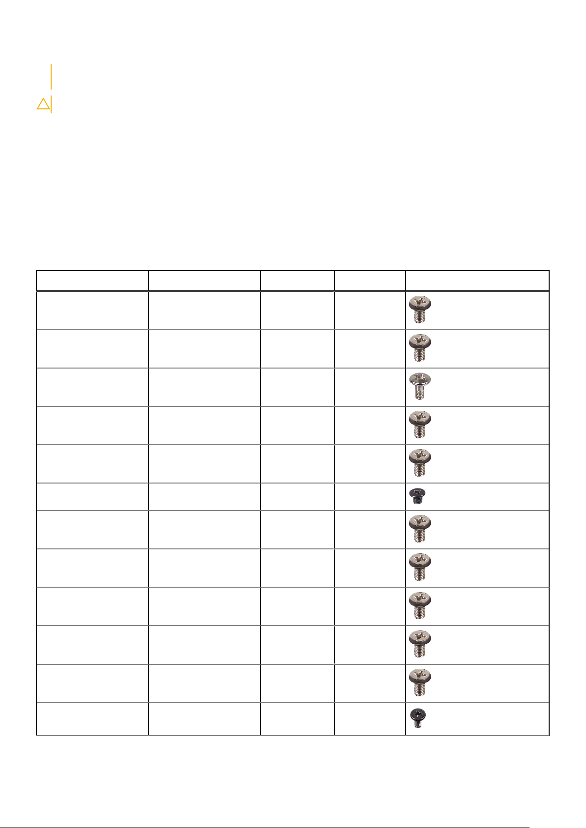
Table 1. Screw list
Component Secured to Screw type Quantity Screw image
Camera Middle frame M3x5 2
Chassis fan Middle frame M3x5 3
Front bezel Middle frame Step-type
M3x5.6
I/O board Middle frame M3x5 4
Hard-drive bracket Middle frame M3x5 1
Hard drive Hard-drive bracket M3x3.5 3
I/O panel Middle frame M3x5 9
I/O board Middle frame M3x5 4
I/O bracket Middle frame M3x5 9
Inner frame Middle frame M3x5 9
4
Media-card reader Middle frame M3x5 2
Microphones (4) Middle frame M2x4 4
Before working inside your computer 9
Page 10
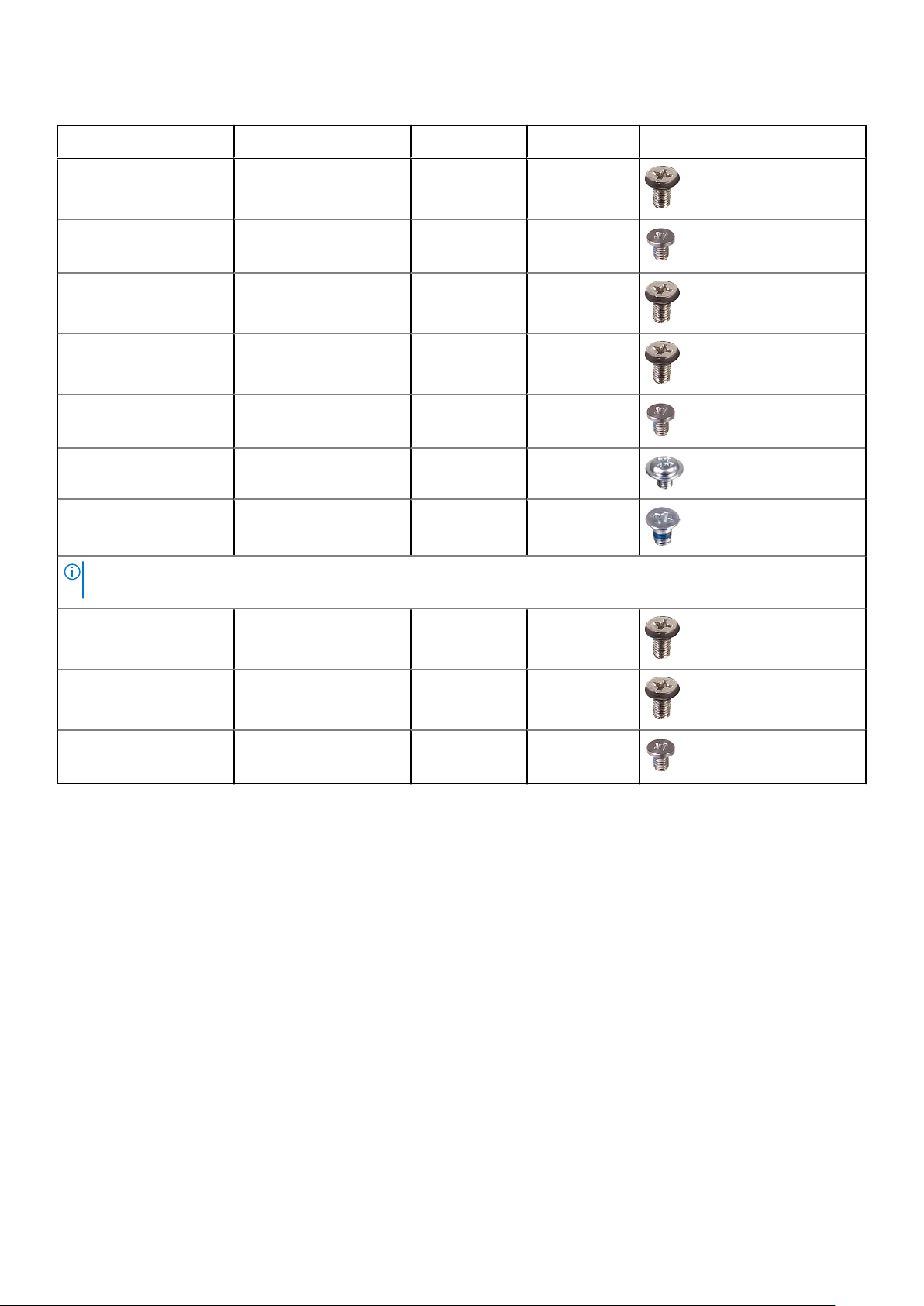
Table 1. Screw list (continued)
Component Secured to Screw type Quantity Screw image
Middle frame Display assembly M3x5 11
Power-button board Middle frame M2x3.5 2
Side I/O-board Middle frame M3x5 2
Side I/O-board bracket Middle frame M3x5 2
Solid-state drive System board M2x3.5 1
Speakers (2) Middle frame Washer-type
M3x4
Stand I/O bracket M4x6 6
NOTE: The number and type of screws securing the stand to the computer is the same for both pedestal and articulating
stand options.
System-board shield System board M3x5 5
System board Middle frame M3x5 5
Wireless card System board M2x3.5 1
4
10 Before working inside your computer
Page 11

After working inside your computer
CAUTION: Leaving stray or loose screws inside your computer may severely damage your computer.
1. Replace all screws and ensure that no stray screws remain inside your computer.
2. Connect any external devices, peripherals, or cables you removed before working on your computer.
3. Replace any media cards, discs, or any other parts that you removed before working on your computer.
4. Connect your computer and all attached devices to their electrical outlets.
5. Turn on your computer.
2
After working inside your computer 11
Page 12
Technical overview
NOTE: Before working inside your computer, read the safety information that shipped with your computer and follow the
steps in Before working inside your computer. After working inside your computer, follow the instructions in After working
inside your computer. For more safety best practices, see the Regulatory Compliance home page at www.dell.com/
regulatory_compliance.
Topics:
• Inside view of your computer
• System board components
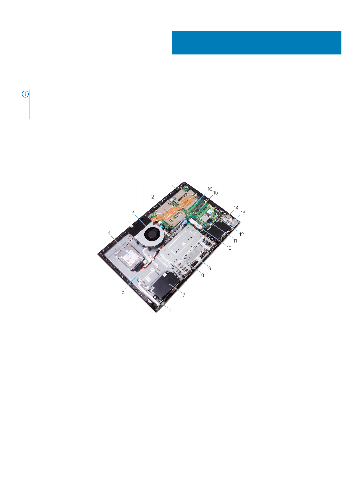
Inside view of your computer
3
Figure 1. : Inside view of your computer
Microphone 2. Processor heat-sink
1.
3. Chassis fan 4. Hard drive
5. Middle frame 6. Power-button board
7. Speaker 8. I/O bracket
9. Camera assembly 10. Solid-state drive
11. Coin-cell assembly 12. Wireless card
13. Side I/O-board 14. Media-card reader
15. Memory module 16. System board
12 Technical overview
Page 13
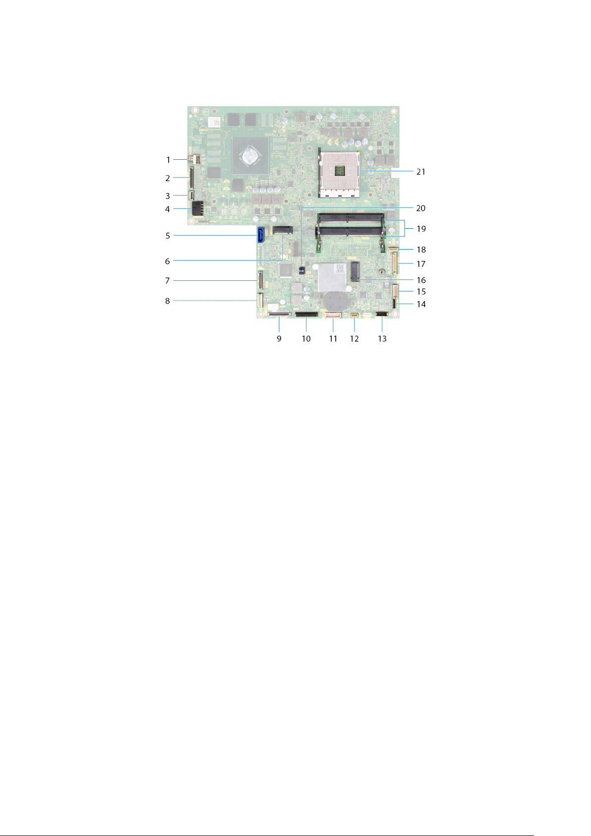
System board components
1. fan-power cable (FAN_SYS) connector 2. display-cable (MB-DISPC) connector
3. power-button board cable (0SDC1) connector 4. power-cable (MB-DCPWR) connector
5. hard-drive data cable (SATA0) connector 6. SSD-card connector (M.2)
7. rear I/O-cable (RUSBC1) connector 8. hard-drive power cable (SATA_PWR1) connector
9. USB Type-C cable (MB-TYPEC1) connector 10. rear I/O-board power cable (RPWRC1) connector
11. rear I/O-board cable (LAUOC1) connector 12. touch-screen cable (TOUCH1) connector
13. speaker-cable (SPEAKER) connector 14. media-card reader cable (SDRDC1) connector
15. side I/O-board cable (MB-SUSBC) connector 16. wireless-card slot
17. camera-cable (WEBCAM) connector 18. microphones-cable (DMIC1) connectors
19. memory-modules (2) slots 20. CMOS/Password jumper
21. processor socket
Technical overview 13
Page 14
Removing the back cover
NOTE: Before working inside your computer, read the safety information that shipped with your computer and follow the
steps in Before working inside your computer. After working inside your computer, follow the instructions in After working
inside your computer. For more safety best practices, see the Regulatory Compliance home page at www.dell.com/
regulatory_compliance.
Topics:
• Procedure
Procedure
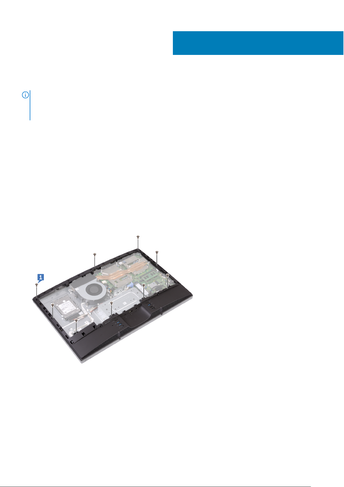
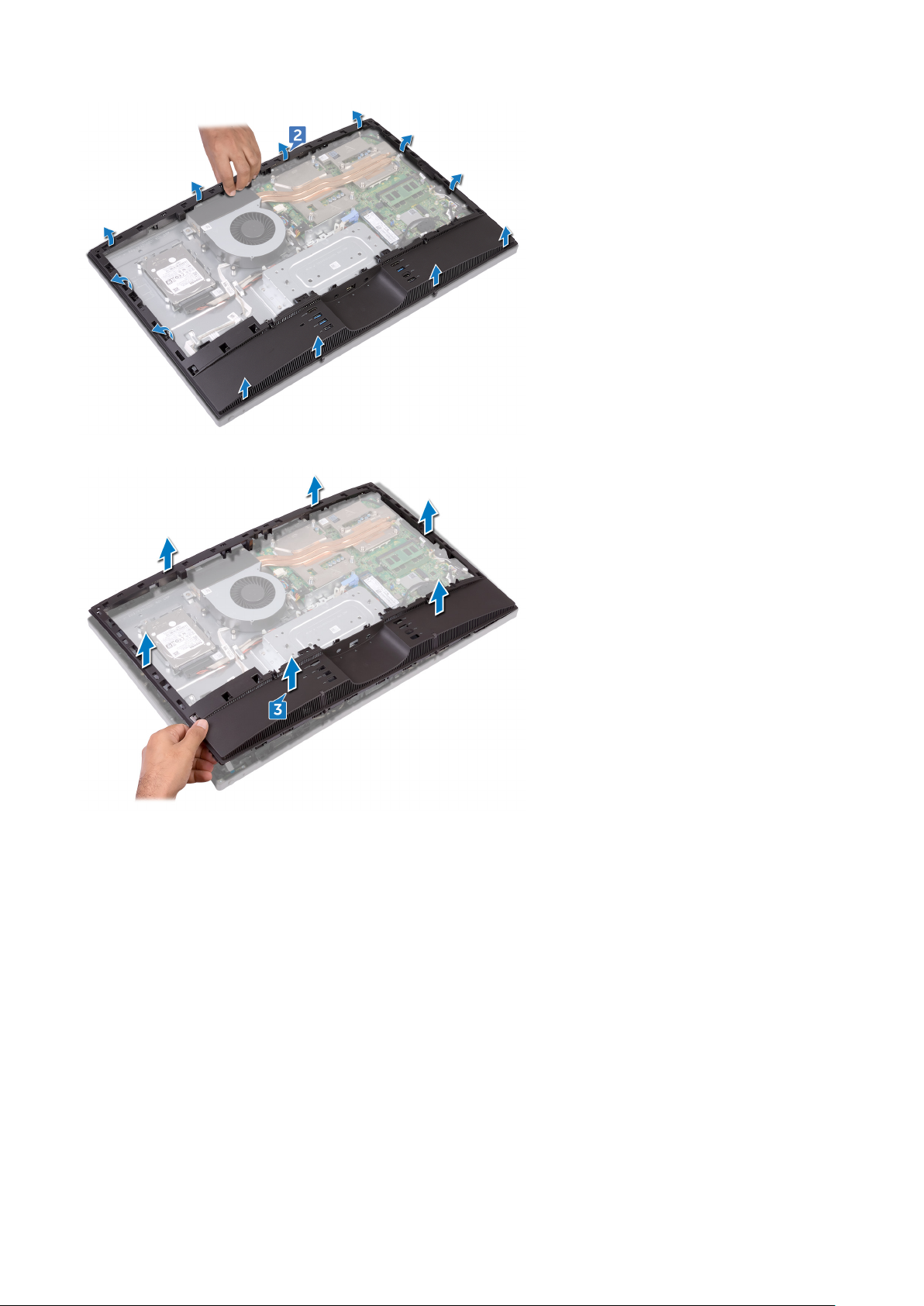
1. Loosen the two captive screws that secure the back cover to the inner frame.
2. Slide and lift the back cover off the inner frame.
4
14 Removing the back cover
Page 15

Replacing the back cover
NOTE: Before working inside your computer, read the safety information that shipped with your computer and follow the
steps in Before working inside your computer. After working inside your computer, follow the instructions in After working
inside your computer. For more safety best practices, see the Regulatory Compliance home page at www.dell.com/
regulatory_compliance.
Topics:
• Procedure
Procedure
1. Align the tabs on the back cover with the slots on the inner frame.
2. Slide the back cover towards the bottom of the computer and snap the back cover in place.
3. Tighten the captive screws that secure the back cover to the inner frame.
5
Replacing the back cover 15
Page 16
Removing the stand
NOTE: Before working inside your computer, read the safety information that shipped with your computer and follow the
steps in Before working inside your computer. After working inside your computer, follow the instructions in After working
inside your computer. For more safety best practices, see the Regulatory Compliance home page at www.dell.com/
regulatory_compliance.
Topics:
• Prerequisites
• Procedure
Prerequisites
Remove the back cover.
Procedure
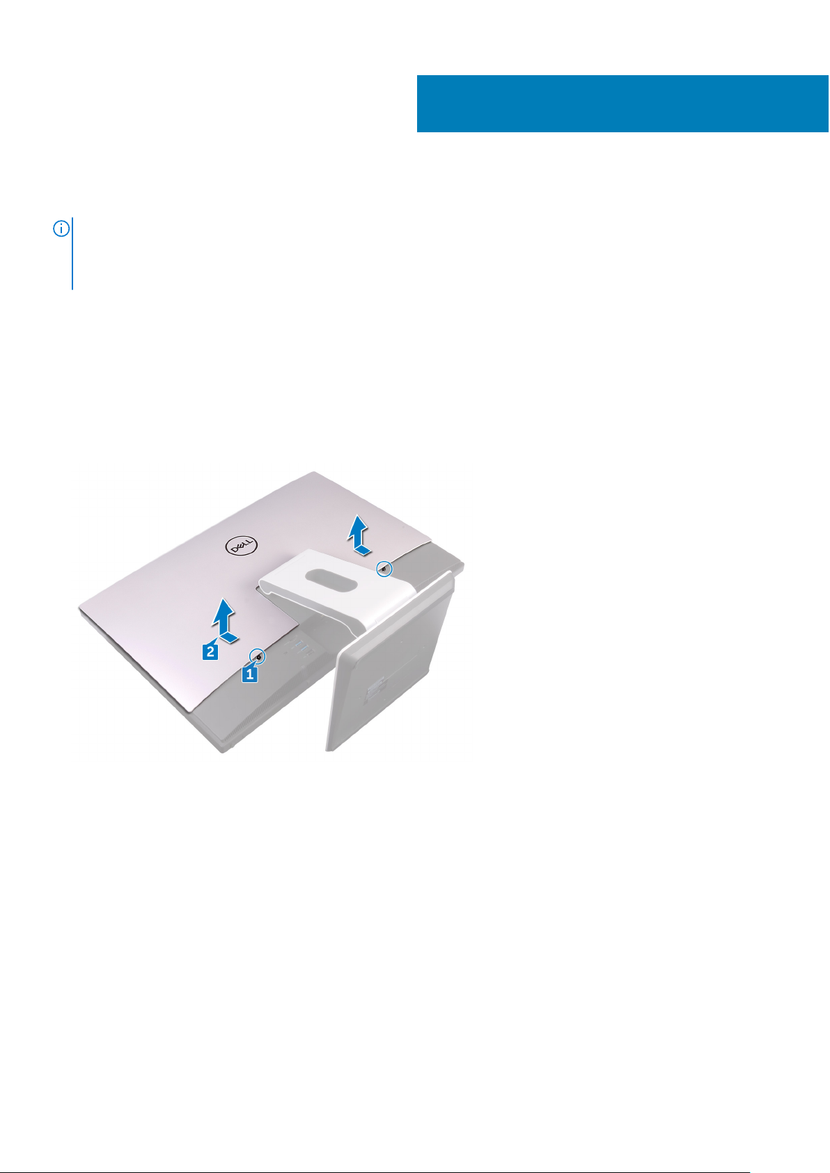
6
NOTE: The removal and replacement process is the same for articulating and pedestal stands.
1. Remove the six screws (M4x6) that secure the stand to the middle frame.
2. Forcefully lift the stand off the I/O bracket. A snapping sound should be heard when the stand is removed correctly.
NOTE: Exercise caution when removing the stand so as to not damage the chassis fan.
16 Removing the stand
Page 17

Replacing the stand
NOTE: Before working inside your computer, read the safety information that shipped with your computer and follow the
steps in Before working inside your computer. After working inside your computer, follow the instructions in After working
inside your computer. For more safety best practices, see the Regulatory Compliance home page at www.dell.com/
regulatory_compliance.
Topics:
• Procedure
• Post-requisites
Procedure
NOTE: The following procedure applies for both articulating and pedestal stand options.
1. Place the tabs on the stand into the slots on the inner frame and snap them into place.
2. Align the screw holes on the stand with the screw holes on the middle frame.
3. Replace the six screws (M4x6) that secure the stand to the middle frame.
7
Post-requisites
Replace the back cover.
Replacing the stand 17
Page 18
Removing the hard drive
NOTE: Before working inside your computer, read the safety information that shipped with your computer and follow the
steps in Before working inside your computer. After working inside your computer, follow the instructions in After working
inside your computer. For more safety best practices, see the Regulatory Compliance home page at www.dell.com/
regulatory_compliance.
CAUTION: Hard drives are fragile. Exercise care when handling the hard drive.
CAUTION: To avoid data loss, do not remove the hard drive while the computer is in sleep or on state.
Topics:
• Prerequisites
• Procedure
Prerequisites
Remove the back cover.
8
Procedure
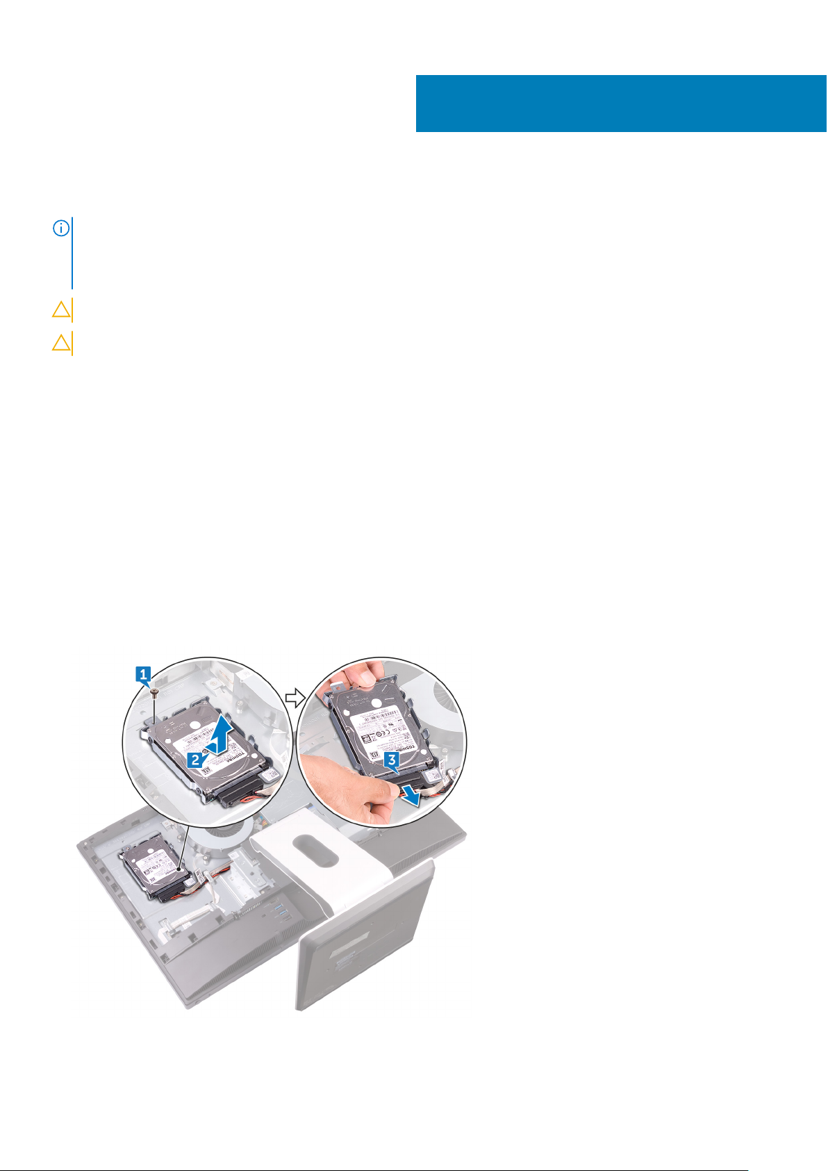
1. Remove the screw (M3x5) that secures the hard-drive assembly to the middle frame.
2. Slide and lift the hard-drive assembly from the middle frame.
3. Disconnect the hard-drive data and power cable (SATA0 and SATA_PWR1) from the hard-drive assembly.
4. Remove the three screws (M3x3.5) that secure the hard drive to the hard-drive bracket.
5. Lift the hard drive off the hard-drive bracket.
18 Removing the hard drive
Page 19
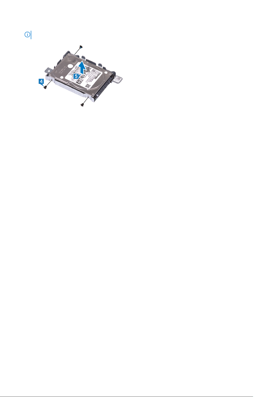
NOTE: Note the orientation of the hard drive so that you can replace it correctly.
Removing the hard drive 19
Page 20

Replacing the hard drive
NOTE: Before working inside your computer, read the safety information that shipped with your computer and follow the
steps in Before working inside your computer. After working inside your computer, follow the instructions in After working
inside your computer. For more safety best practices, see the Regulatory Compliance home page at www.dell.com/
regulatory_compliance.
CAUTION: Hard drives are fragile. Exercise care when handling the hard drive.
Topics:
• Procedure
• Post-requisites
Procedure
1. Align the screw holes on the disk drive with the screw holes on the disk-drive bracket.
2. Replace the three screws (M3x3.5) that screw the hard drive to the hard-drive bracket.
3. Connect the hard-drive data and power cable (SATA0 and SATA_PWR1) to the hard-drive assembly.
4. Place and slide the hard-drive assembly into the middle frame.
5. Replace the screw (M3x5) that secures the hard-drive assembly to the middle frame.
9
Post-requisites
Replace the back cover.
20 Replacing the hard drive
Page 21
Removing the inner frame
NOTE: Before working inside your computer, read the safety information that shipped with your computer and follow the
steps in Before working inside your computer. After working inside your computer, follow the instructions in After working
inside your computer. For more safety best practices, see the Regulatory Compliance home page at www.dell.com/
regulatory_compliance.
Topics:
• Prerequisites
• Procedure
Prerequisites
1. Remove the back cover.
2. Remove the stand.
Procedure
10
1. Remove the nine screws (M3x5) that secure the inner frame to the middle frame.
2. Gently pry the inner frame from the sides off the middle frame.
Removing the inner frame 21
Page 22
3. Lift the inner frame from the middle frame.
22 Removing the inner frame
Page 23

Replacing the inner frame
NOTE: Before working inside your computer, read the safety information that shipped with your computer and follow the
steps in Before working inside your computer. After working inside your computer, follow the instructions in After working
inside your computer. For more safety best practices, see the Regulatory Compliance home page at www.dell.com/
regulatory_compliance.
Topics:
• Procedure
• Post-requisites
Procedure
1. Sliding the inner frame at an angle, align the audio-out port through the respective slot on the inner frame and the screw
holes on the inner frame with the screw holes on the middle frame.
2. Starting from the edge closest to the I/O bracket, press the inner frame down until it clicks in place.
3. Replace the nine screws (M3x5) that secure the inner frame to the middle frame.
11
Post-requisites
1. Replace the stand.
2. Replace the back cover.
Replacing the inner frame 23
Page 24
Removing the camera
NOTE: Before working inside your computer, read the safety information that shipped with your computer and follow the
steps in Before working inside your computer. After working inside your computer, follow the instructions in After working
inside your computer. For more safety best practices, see the Regulatory Compliance home page at www.dell.com/
regulatory_compliance.
Topics:
• Prerequisites
• Procedure
Prerequisites
1. Remove the back cover.
2. Remove the stand.
3. Remove the inner frame.
12
Procedure
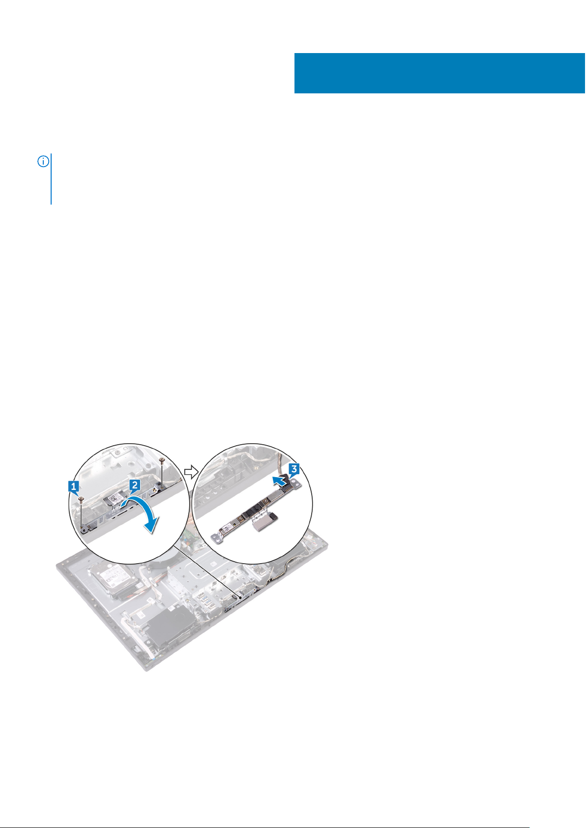
1. Remove the two screws (M3x5) that secure the camera assembly to the middle frame.
2. Lift the camera assembly off the middle frame.
3. Disconnect the camera cable (WEBCAM) from the camera assembly.
24 Removing the camera
Page 25

Replacing the camera
NOTE: Before working inside your computer, read the safety information that shipped with your computer and follow the
steps in Before working inside your computer. After working inside your computer, follow the instructions in After working
inside your computer. For more safety best practices, see the Regulatory Compliance home page at www.dell.com/
regulatory_compliance.
Topics:
• Procedure
• Post-requisites
Procedure
1. Connect the camera cable (WEBCAM) to the camera assembly.
2. Turn the camera assembly and align the screw holes on the camera assembly with the screw holes on the middle frame.
3. Replace the two screws (M3x5) that secure camera assembly to the middle frame.
13
Post-requisites
1. Replace the inner frame.
2. Replace the stand.
3. Replace the back cover.
Replacing the camera 25
Page 26
Removing the microphones
NOTE: Before working inside your computer, read the safety information that shipped with your computer and follow the
steps in Before working inside your computer. After working inside your computer, follow the instructions in After working
inside your computer. For more safety best practices, see the Regulatory Compliance home page at www.dell.com/
regulatory_compliance.
Topics:
• Prerequisites
• Procedure
Prerequisites
1. Remove the back cover.
2. Remove the stand.
3. Remove the inner frame.
14
Procedure
1. Disconnect the microphones cable (DMIC1) from the microphone modules (4).
2. Remove the four screws (M2x4) that secure the microphone modules (4) to the middle frame.
3. Using a plastic scribe, carefully pry and lift the microphone modules (4) off the slots on the middle frame.
26 Removing the microphones
Page 27

Replacing the microphones
NOTE: Before working inside your computer, read the safety information that shipped with your computer and follow the
steps in Before working inside your computer. After working inside your computer, follow the instructions in After working
inside your computer. For more safety best practices, see the Regulatory Compliance home page at www.dell.com/
regulatory_compliance.
Topics:
• Procedure
• Post-requisites
Procedure
1. Connect the microphones cable (DMIC1) to the microphone modules.
2. Align the microphone modules (4) with their slots on the middle frame.
3. Route the microphones cable (DMIC1) through the routing guides on middle frame.
4. Replace the four screws (M2x4) that secure the microphone module to the middle frame.
15
Post-requisites
1. Replace the inner frame.
2. Replace the stand.
3. Replace the back cover.
Replacing the microphones 27
Page 28

Removing the power-button board
NOTE: Before working inside your computer, read the safety information that shipped with your computer and follow the
steps in Before working inside your computer. After working inside your computer, follow the instructions in After working
inside your computer. For more safety best practices, see the Regulatory Compliance home page at www.dell.com/
regulatory_compliance.
Topics:
• Prerequisites
• Procedure
Prerequisites
1. Remove the back cover.
2. Remove the stand.
3. Remove the inner frame.
16
Procedure
1. Remove the two screws (M2x3.5) that secure the power-button board shield to the middle frame.
2. Slide and lift the power-button board off the middle frame.
3. Open the latch, disconnecting the power-button board cable (0SDC1) from its slot on the power-button board. Then,
remove the power-button board cable (0SDC1) from the routing guide on the middle frame.
28 Removing the power-button board
Page 29

17
Replacing the power-button board
NOTE: Before working inside your computer, read the safety information that shipped with your computer and follow the
steps in Before working inside your computer. After working inside your computer, follow the instructions in After working
inside your computer. For more safety best practices, see the Regulatory Compliance home page at www.dell.com/
regulatory_compliance.
Topics:
• Procedure
• Post-requisites
Procedure
1. Connect the power-button board cable (0SDC1) to the power-button board and route the cable through the routing guide
on the middle frame.
2. Align the power-button board to the slot on the middle frame and place the power-button board on the middle frame.
3. Align the screw holes on power-button board shield to the screw holes on middle frame.
4. Replace the two screws (M2x3.5) that secure the power-button board shield to middle frame.
Post-requisites
1. Replace the inner frame.
2. Replace the stand.
3. Replace the back cover.
Replacing the power-button board 29
Page 30

Removing the front bezel
NOTE: Before working inside your computer, read the safety information that shipped with your computer and follow the
steps in Before working inside your computer. After working inside your computer, follow the instructions in After working
inside your computer. For more safety best practices, see the Regulatory Compliance home page at www.dell.com/
regulatory_compliance.
Topics:
• Prerequisites
• Procedure
Prerequisites
1. Remove the back cover.
2. Remove the stand.
3. Remove the inner frame.
4. Remove the camera.
18
Procedure
1. Remove the four screws (Step-type M3x5.6) that secure the front bezel to the middle frame.
2. Lift and hold in place the system at an angle.
3. Release the ten latches securing the front bezel to the display assembly.
30 Removing the front bezel
Page 31

4. Gently lift the front bezel off the display assembly.
Removing the front bezel 31
Page 32

Replacing the front bezel
NOTE: Before working inside your computer, read the safety information that shipped with your computer and follow the
steps in Before working inside your computer. After working inside your computer, follow the instructions in After working
inside your computer. For more safety best practices, see the Regulatory Compliance home page at www.dell.com/
regulatory_compliance.
Topics:
• Procedure
• Post-requisites
Procedure
1. Aligning the latches on the front bezel to the slots on the middle frame, snap the front bezel back in place.
2. Replace the four screws (Step-type M3x5.6) that secure the front bezel to the middle frame
Post-requisites
19
1. Replace the camera.
2. Replace the inner frame.
3. Replace the stand.
4. Replace the back cover.
32 Replacing the front bezel
Page 33

Removing the system-board shield
NOTE: Before working inside your computer, read the safety information that shipped with your computer and follow the
steps in Before working inside your computer. After working inside your computer, follow the instructions in After working
inside your computer. For more safety best practices, see the Regulatory Compliance home page at www.dell.com/
regulatory_compliance.
Topics:
• Prerequisites
• Procedure
Prerequisites
Remove the back cover.
Procedure
20
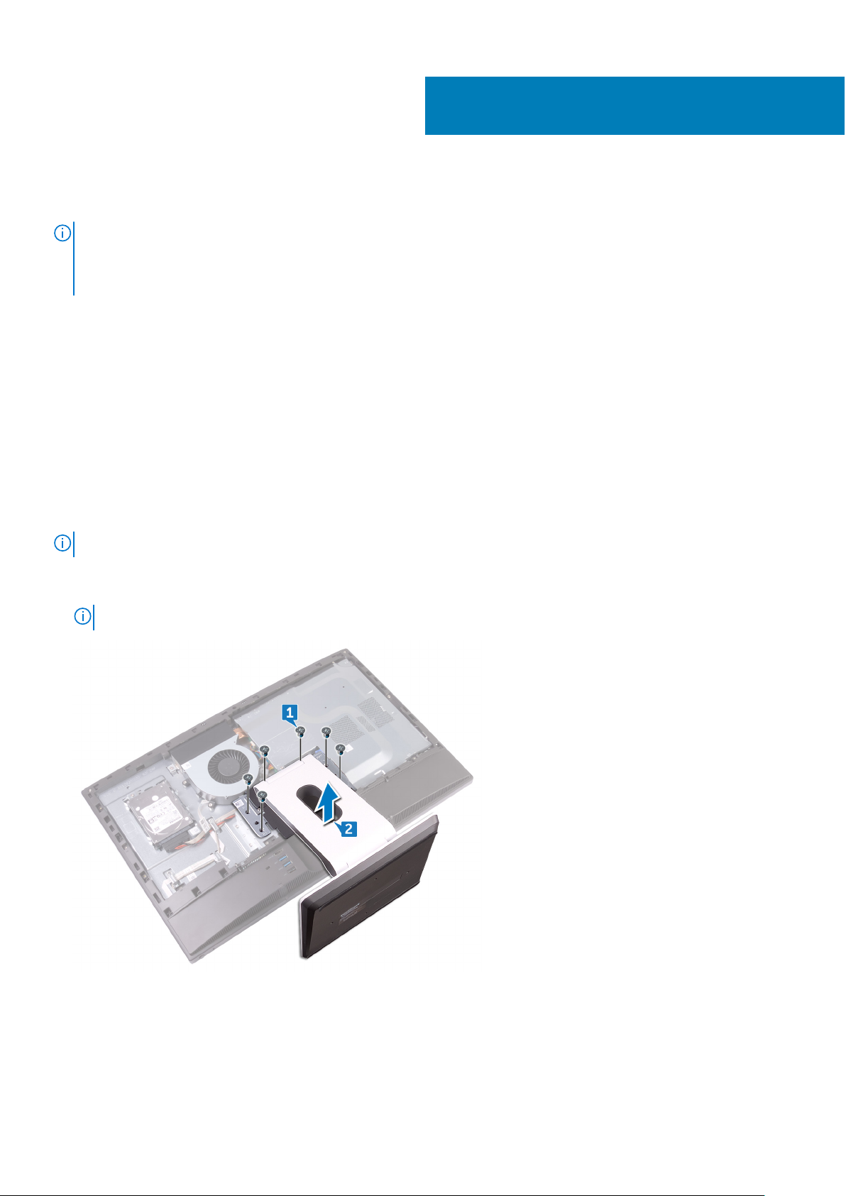
1. Remove the five screws (M3x5) that secure the system-board shield to the middle frame.
2. Lift the system-board shield off the middle frame.
Removing the system-board shield 33
Page 34

Replacing the system-board shield
NOTE: Before working inside your computer, read the safety information that shipped with your computer and follow the
steps in Before working inside your computer. After working inside your computer, follow the instructions in After working
inside your computer. For more safety best practices, see the Regulatory Compliance home page at www.dell.com/
regulatory_compliance.
Topics:
• Procedure
• Post-requisites
Procedure
1. Align the screw holes on the system-board shield with the screw holes on the middle frame.
2. Replace the five screws (M3x5) that secure the system-board shield to the middle frame.
Post-requisites
21
Replace the back cover.
34 Replacing the system-board shield
Page 35

Removing the chassis fan
NOTE: Before working inside your computer, read the safety information that shipped with your computer and follow the
steps in Before working inside your computer. After working inside your computer, follow the instructions in After working
inside your computer. For more safety best practices, see the Regulatory Compliance home page at www.dell.com/
regulatory_compliance.
Topics:
• Prerequisites
• Procedure
Prerequisites
1. Remove the back cover.
2. Remove the system-board shield.
Procedure
22
1. Disconnect the fan-power cable (FAN_SYS) from its connector on the system board.
2. Remove the three screws (M3x5) that secure the chassis fan to the middle frame.
3. Lift the chassis fan off the middle frame.
Removing the chassis fan 35
Page 36

Replacing the chassis fan
NOTE: Before working inside your computer, read the safety information that shipped with your computer and follow the
steps in Before working inside your computer. After working inside your computer, follow the instructions in After working
inside your computer. For more safety best practices, see the Regulatory Compliance home page at www.dell.com/
regulatory_compliance.
Topics:
• Procedure
• Post-requisites
Procedure
1. Align the screw holes on the chassis fan with the screw holes on the middle frame.
2. Replace the three screws (M3x5) that secure the chassis fan to the middle frame.
3. Connect the fan-power cable to the system board.
23
Post-requisites
1. Replace the system-board shield.
2. Replace the back cover.
36 Replacing the chassis fan
Page 37

Removing the speakers
NOTE: Before working inside your computer, read the safety information that shipped with your computer and follow the
steps in Before working inside your computer. After working inside your computer, follow the instructions in After working
inside your computer. For more safety best practices, see the Regulatory Compliance home page at www.dell.com/
regulatory_compliance.
Topics:
• Prerequisites
• Procedure
Prerequisites
1. Remove the back cover.
2. Remove the stand.
3. Remove the inner frame.
4. Remove the system-board shield.
24
Procedure
1. Disconnect the side I/O-board cable (MB-SUSBC) from the system board and remove it from the routing guide on the
middle frame.
2. Disconnect the speaker cable (SPEAKER) from the system board and remove it from the routing guide on the middle frame.
3. Remove the four screws (Washer-type M3x4) that secure the speakers to the middle frame.
4. Remove the speaker cable (SPEAKER) from the routing guide on the I/O bracket.
5. Lift the speakers along with the cable off the middle frame.
Removing the speakers 37
Page 38

25
Replacing the speakers
NOTE: Before working inside your computer, read the safety information that shipped with your computer and follow the
steps in Before working inside your computer. After working inside your computer, follow the instructions in After working
inside your computer. For more safety best practices, see the Regulatory Compliance home page at www.dell.com/
regulatory_compliance.
Topics:
• Procedure
• Post-requisites
Procedure
1. Align the screw holes on the speakers to the screw holes on the middle frame.
2. Route the speaker (SPEAKER) cable through the routing guide on the I/O bracket.
3. Replace the four screws (Washer-type M3x4) that secure the speakers to the middle frame.
4. Reconnect the speaker cable (SPEAKER) from the system board and route the cable through the routing guide on the
middle frame.
5. Reconnect the side I/O-board cable (MB-SUSBC) from the system board and route the cable through the routing guide on
the middle frame.
Post-requisites
1. Replace the system-board shield.
2. Replace the inner frame.
3. Replace the stand.
4. Replace the back cover.
38 Replacing the speakers
Page 39

Removing the side I/O-board
NOTE: Before working inside your computer, read the safety information that shipped with your computer and follow the
steps in Before working inside your computer. After working inside your computer, follow the instructions in After working
inside your computer. For more safety best practices, see the Regulatory Compliance home page at www.dell.com/
regulatory_compliance.
Topics:
• Prerequisites
• Procedure
Prerequisites
1. Remove the back cover.
2. Remove the stand.
3. Remove the inner frame.
4. Remove the system-board shield.
26
Procedure
Before conducting the following removal procedure, disconnect and remove from the respective routing the following cables:
● Antenna cables from the wireless-card.
● Speaker cable (SPEAKER) from the system board.
● Camera cable (WEBCAM) from the system board.
1. Disconnect the side I/O-board cable (MB-SUSBC) from the side I/O-board.
2. Disconnect the media-card reader cable (SDRDC1) from the media-card reader board.
3. Release the side I/O-board and media-card reader cables (MB-SUSBC and SDRDC1) from the routing guides on the middle
frame.
4. Remove the two screws (M3x5) that secure the side I/O-bracket to the middle frame.
5. Lift the side I/O-bracket from the middle frame.
Removing the side I/O-board 39
Page 40

6. Remove the four screws (M3x5) that secure the side I/O-board and the media-card reader board to the side I/O-bracket.
7. Slide and lift the side I/O-board from the side I/O-bracket.
8. Lift the media-card reader board from the side I/O-bracket.
40
Removing the side I/O-board
Page 41

27
Replacing the side I/O-board
NOTE: Before working inside your computer, read the safety information that shipped with your computer and follow the
steps in Before working inside your computer. After working inside your computer, follow the instructions in After working
inside your computer. For more safety best practices, see the Regulatory Compliance home page at www.dell.com/
regulatory_compliance.
Topics:
• Procedure
• Post-requisites
Procedure
After conducting the following replacement procedure, and if the following cables were disconnected and removed in the
removal process reconnect and route through the respective routing guides the following cables:
● Antenna cables from the wireless-card.
● Speaker cable (SPEAKER) to the system board.
● Camera cable (WEBCAM) to the system board.
1. Replace the media-card reader board and the side I/O-board aligning the screw holes with the screw holes on the side I/Obracket.
2. Replace the four screws (M3x5) that secure the side I/O-board and the media-card reader board to the side I/O-bracket.
3. Replace the side I/O-bracket aligning the guiding pins and screw holes to the respective slots and screw holes on the middle
frame.
4. Replace the two screws (M3x5) that secure the side I/O-bracket to the middle frame.
5. Route the side I/O-board and media-card reader cables (MB-SUSBC and SDRDC1) through the routing guides on middle
frame.
6. Connect the side I/O-board cable (MB-SUSBC) to the side I/O-board
7. Connect the media-card reader cable (SDRDC1) to the media-card reader board.
Post-requisites
1. Replace the system-board shield.
2. Replace the inner frame.
3. Replace the stand.
4. Replace the back cover.
Replacing the side I/O-board 41
Page 42

Removing the coin-cell battery
NOTE: Before working inside your computer, read the safety information that shipped with your computer and follow the
steps in Before working inside your computer. After working inside your computer, follow the instructions in After working
inside your computer. For more safety best practices, see the Regulatory Compliance home page at www.dell.com/
regulatory_compliance.
CAUTION: Removing the coin-cell battery resets the BIOS setup program’s settings to default. It is
recommended that you note the BIOS setup program’s settings before removing the coin-cell battery.
Topics:
• Prerequisites
• Procedure
Prerequisites
1. Remove the back cover.
2. Remove the system-board shield.
28
Procedure
1. Pull the coin-cell rubber cap from the system board.
2. Using a plastic scribe, press on the metal clip. Then carefully pry and lift off the coin-cell battery from the coin-cell holder on
the system board.
42 Removing the coin-cell battery
Page 43

29
Replacing the coin-cell battery
NOTE: Before working inside your computer, read the safety information that shipped with your computer and follow the
steps in Before working inside your computer. After working inside your computer, follow the instructions in After working
inside your computer. For more safety best practices, see the Regulatory Compliance home page at www.dell.com/
regulatory_compliance.
Topics:
• Procedure
• Post-requisites
Procedure
1. With the positive-side facing up, insert the coin-cell battery into the battery socket on the system board and press down the
battery into place.
2. Adhere the coin-cell rubber cap onto the positive-side of the coin cell battery.
Post-requisites
1. Replace the system-board shield.
2. Replace the back cover.
Replacing the coin-cell battery 43
Page 44

Removing the memory modules
NOTE: Before working inside your computer, read the safety information that shipped with your computer and follow the
steps in Before working inside your computer. After working inside your computer, follow the instructions in After working
inside your computer. For more safety best practices, see the Regulatory Compliance home page at www.dell.com/
regulatory_compliance.
Topics:
• Prerequisites
• Procedure
Prerequisites
1. Remove the back cover.
2. Remove the system-board shield.
Procedure
30
1. Locate the memory modules on the system board.
2. Using your fingertips, spread apart the securing clips at each end of the memory-module slot until the memory module pops
up.
3. Slide and remove the memory module from the memory-module slot.
44 Removing the memory modules
Page 45

Removing the memory modules 45
Page 46

Replacing the memory modules
NOTE: Before working inside your computer, read the safety information that shipped with your computer and follow the
steps in Before working inside your computer. After working inside your computer, follow the instructions in After working
inside your computer. For more safety best practices, see the Regulatory Compliance home page at www.dell.com/
regulatory_compliance.
Topics:
• Procedure
• Post-requisites
Procedure
1. Align the notch on the memory module with the tab on the memory-module slot.
2. Slide the memory module firmly into the slot at an angle.
3. Press the memory module down until it clicks into place.
NOTE: If you do not hear the click, remove the memory module and reinstall it.
31
Post-requisites
1. Replace the system-board shield.
2. Replace the back cover.
46 Replacing the memory modules
Page 47

Removing the solid-state drive
NOTE: Before working inside your computer, read the safety information that shipped with your computer and follow the
steps in Before working inside your computer. After working inside your computer, follow the instructions in After working
inside your computer. For more safety best practices, see the Regulatory Compliance home page at www.dell.com/
regulatory_compliance.
CAUTION: Solid-state drives are fragile. Exercise care when handling the solid-state drive.
CAUTION: To avoid data loss, do not remove the solid-state drive while the computer is in sleep or on state.
Topics:
• Prerequisites
• Procedure
Prerequisites
1. Remove the back cover.
2. Remove the system-board shield.
32
Procedure
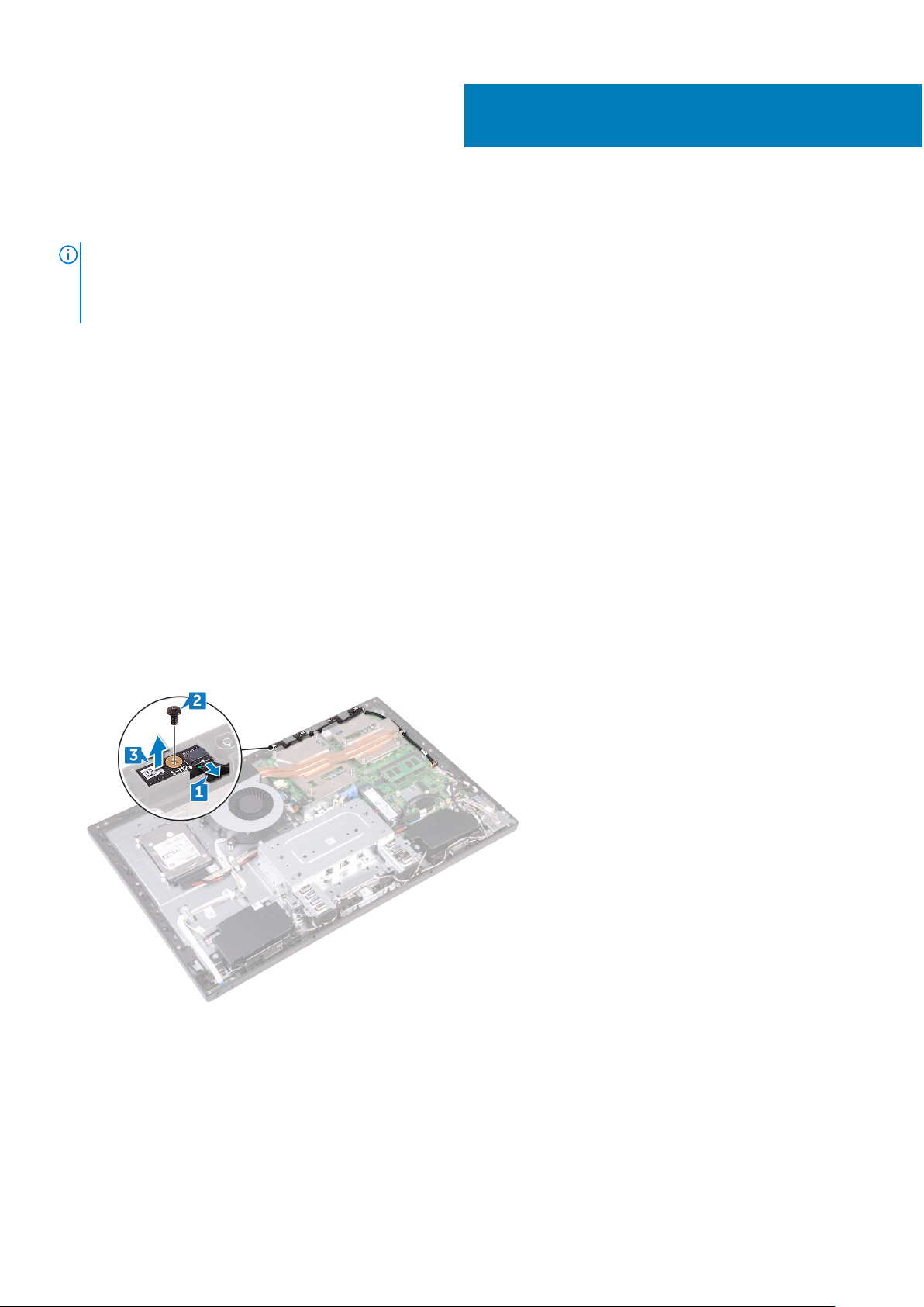
1. Locate the solid-state drive on the system board.
2. Remove the screw (M2x3.5) that secures the solid-state drive to the system board.
3. Slide and remove the solid-state drive from the solid-state drive slot.
Removing the solid-state drive 47
Page 48

48 Removing the solid-state drive
Page 49

Replacing the solid-state drive
NOTE: Before working inside your computer, read the safety information that shipped with your computer and follow the
steps in Before working inside your computer. After working inside your computer, follow the instructions in After working
inside your computer. For more safety best practices, see the Regulatory Compliance home page at www.dell.com/
regulatory_compliance.
CAUTION: Solid-state drives are fragile. Exercise care when handling the solid-state drive.
Topics:
• Procedure
• Post-requisites
Procedure
1. Align the notch on the solid-state drive with the tab on the solid-state drive slot.
2. Slide the solid-state drive into the solid-state drive slot.
3. Replace the screw (M2x3.5) that secures the solid-state drive to the system board.
33
Post-requisites
1. Replace the system-board shield.
2. Replace the back cover.
Replacing the solid-state drive 49
Page 50

Removing the wireless card
NOTE: Before working inside your computer, read the safety information that shipped with your computer and follow the
steps in Before working inside your computer. After working inside your computer, follow the instructions in After working
inside your computer. For more safety best practices, see the Regulatory Compliance home page at www.dell.com/
regulatory_compliance.
Topics:
• Prerequisites
• Procedure
Prerequisites
1. Remove the back cover.
2. Remove the system-board shield.
Procedure
34
1. Locate the wireless card on the system board.
2. Remove the screw (M2x3.5) that secures the wireless card to the system board.
3. Lift the wireless-card shield off the system board.
4. Disconnect the antenna cables from the wireless card.
5. Slide and remove the wireless card out of the wireless-card slot.
50 Removing the wireless card
Page 51

Removing the wireless card 51
Page 52

35
Replacing the wireless card
NOTE: Before working inside your computer, read the safety information that shipped with your computer and follow the
steps in Before working inside your computer. After working inside your computer, follow the instructions in After working
inside your computer. For more safety best practices, see the Regulatory Compliance home page at www.dell.com/
regulatory_compliance.
Topics:
• Procedure
• Post-requisites
Procedure
CAUTION: To avoid damaging the wireless card, do not place any cables under it.
1. Align the notch on the wireless card with the tab on the wireless-card slot and slide the wireless card into the wireless-card
slot.
2. Connect the antenna cables to the wireless card.
The following table provides the antenna-cable color scheme for the wireless card supported by your computer:
Table 2. : Wirelesscard colour scheme
Connectors on the wireless card Antenna-cable color
Main (white triangle) White
Auxiliary (black triangle) Black
3. Press down the other end of the wireless card and align the screw hole on the wireless-card shield and wireless card with
the screw hole on the system board.
4. Replace the screw (M2x3.5) that secures the wireless-card bracket and the wireless card to the system board.
52 Replacing the wireless card
Page 53

Post-requisites
1. Replace the system-board shield.
2. Replace the back cover.
Replacing the wireless card 53
Page 54

Removing the processor heat-sink
NOTE: Before working inside your computer, read the safety information that shipped with your computer and follow the
steps in Before working inside your computer. After working inside your computer, follow the instructions in After working
inside your computer. For more safety best practices, see the Regulatory Compliance home page at www.dell.com/
regulatory_compliance.
CAUTION: For maximum cooling of the processor, do not touch the heat transfer areas on the heat sink. The oils
in your skin can reduce the heat transfer capability of the thermal grease.
Topics:
• Prerequisites
• Procedure for computers with discrete graphics
Prerequisites
1. Remove the back cover.
2. Remove the system-board shield.
36
Procedure for computers with discrete graphics
NOTE:
Depending on the configuration you ordered, the appearance of the processor heat-sink and the number of screws
may differ.
1. In sequential order (indicated on the heat sink), loosen the captive screws that secure the processor heat-sink to the system
board.
2. Lift the processor heat-sink off the system board.
NOTE: Computers that support the AMD Radeon RX560 graphics configuration are shipped with 9 captive screws.
NOTE: Computers that ship with only integrated graphics processors are shipped with 5 captive screws.
54 Removing the processor heat-sink
Page 55

Removing the processor heat-sink 55
Page 56

37
Replacing the processor heat-sink
NOTE: Before working inside your computer, read the safety information that shipped with your computer and follow the
steps in Before working inside your computer. After working inside your computer, follow the instructions in After working
inside your computer. For more safety best practices, see the Regulatory Compliance home page at www.dell.com/
regulatory_compliance.
CAUTION: For maximum cooling of the processor, do not touch the heat transfer areas on the heat sink. The oils
in your skin can reduce the heat transfer capability of the thermal grease.
Topics:
• Procedure
• Post-requisites
Procedure
1. Align the captive screws on the processor heat-sink with the screw holes on the system board.
2. In reverse sequential order (indicated on the processor heat-sink), tighten the captive screws that secure the processor
heat-sink to the system board.
Post-requisites
1. Replace the system-board shield.
2. Replace the back cover.
56 Replacing the processor heat-sink
Page 57

Removing the processor
NOTE: Before working inside your computer, read the safety information that shipped with your computer and follow the
steps in Before working inside your computer. After working inside your computer, follow the instructions in After working
inside your computer. For more safety best practices, see the Regulatory Compliance home page at www.dell.com/
regulatory_compliance.
Topics:
• Prerequisites
• Procedure
Prerequisites
1. Remove the back cover.
2. Remove the system-board shield.
3. Remove the processor heat sink.
38
Procedure
1. Locate the processor on the system board.
2. Press the release-lever down and then pull it outwards to release it from the securing tab.
3. Pull up the release-lever completely to unlock the processor.
4. Gently lift the processor and remove it from the processor socket.
Removing the processor 57
Page 58

58 Removing the processor
Page 59

Replacing the processor
NOTE: Before working inside your computer, read the safety information that shipped with your computer and follow the
steps in Before working inside your computer. After working inside your computer, follow the instructions in After working
inside your computer. For more safety best practices, see the Regulatory Compliance home page at www.dell.com/
regulatory_compliance.
CAUTION: If either the processor or the heat sink is replaced, use the thermal grease provided in the kit to
ensure that thermal conductivity is achieved.
NOTE: A new processor ships with a thermal pad in the package. In some cases, the processor may ship with the thermal
pad attached to it.
Topics:
• Procedure
• Post-requisites
Procedure
39
1. Ensure that the release lever on the processor socket is fully extended in the open position.
CAUTION:
the processor socket. When the processor is properly seated, all four corners are aligned at the same height.
If one or more corners of the processor are higher than the others, the processor is not seated properly.
2. Align the notches on the processor with the tabs on the processor socket and place the processor in the processor socket.
CAUTION: Ensure that the processor-cover notch is positioned underneath the alignment post.
3. When the processor is fully seated in the socket, close the processor cover.
4. Pivot the release-lever down and place it under the tab on the processor cover.
The pin-1 corner of the processor has a triangle that aligns with the triangle on the pin-1 corner on
Post-requisites
1. Replace the processor heat sink.
2. Replace the system-board shield.
3. Replace the back cover.
Replacing the processor 59
Page 60

Removing the I/O bracket
NOTE: Before working inside your computer, read the safety information that shipped with your computer and follow the
steps in Before working inside your computer. After working inside your computer, follow the instructions in After working
inside your computer. For more safety best practices, see the Regulatory Compliance home page at www.dell.com/
regulatory_compliance.
Topics:
• Prerequisites
• Procedure
Prerequisites
1. Remove the back cover.
2. Remove the stand.
3. Remove the inner frame.
40
Procedure
1. Remove the nine screws (M3x5) that secure the I/O bracket to the middle frame.
2. Lift the I/O bracket off the middle frame.
60 Removing the I/O bracket
Page 61

Replacing the I/O bracket
NOTE: Before working inside your computer, read the safety information that shipped with your computer and follow the
steps in Before working inside your computer. After working inside your computer, follow the instructions in After working
inside your computer. For more safety best practices, see the Regulatory Compliance home page at www.dell.com/
regulatory_compliance.
Topics:
• Procedure
• Post-requisites
Procedure
1. Align the screw holes on the I/O bracket with the screw holes on the middle frame.
2. Replace the nine screws (M3x5) that secure the I/O bracket to the middle frame.
Post-requisites
41
1. Replace the inner frame.
2. Replace the stand.
3. Replace the back cover.
Replacing the I/O bracket 61
Page 62

Removing the I/O board
NOTE: Before working inside your computer, read the safety information that shipped with your computer and follow the
steps in Before working inside your computer. After working inside your computer, follow the instructions in After working
inside your computer. For more safety best practices, see the Regulatory Compliance home page at www.dell.com/
regulatory_compliance.
Topics:
• Prerequisites
• Procedure
Prerequisites
1. Remove the back cover.
2. Remove the stand.
3. Remove the inner frame.
4. Remove the I/O board bracket.
42
Procedure
1. Open the latch and disconnect the display-panel cable (EDPCN1) from the I/O board.
2. Disconnect the rear I/O-board power cable (RPWRC1) from the I/O board.
3. Using the pull tab, disconnect the display cable (SB-DISPC) from the I/O board.
4. Using the pull tab, disconnect the USB Type-C cable (SB-TYPEC1) from the I/O board.
5. Press down the latch on the power-cable connector and pull the connector to disconnect the power cable (SB-DCPWR)
from the I/O board.
6. Using the pull tab, disconnect the rear I/O cable (RUSBC1) from the I/O board.
7. Open the latch and disconnect the rear I/O-board cable (LAUOC1) from the I/O board.
8. Disconnect the display-converter cable (CONVERTER) from the I/O board.
9. Remove the cables from the routing guide on the I/O board.
62 Removing the I/O board
Page 63

10. Remove the four screws (M3x5) that secure the I/O board to the middle frame.
11. Lift the I/O board off the middle frame.
Removing the I/O board
63
Page 64

Replacing the I/O board
NOTE: Before working inside your computer, read the safety information that shipped with your computer and follow the
steps in Before working inside your computer. After working inside your computer, follow the instructions in After working
inside your computer. For more safety best practices, see the Regulatory Compliance home page at www.dell.com/
regulatory_compliance.
Topics:
• Procedure
• Post-requisites
Procedure
1. Align the screw holes on the I/O board with the screw holes on the middle frame.
2. Replace the four screws (M3x5) that secure the I/O board to the middle frame.
3. Route and connect the following cables through the respective routing guides and connectors on the I/O board:
● Display-converter cable (CONVERTER)
● Rear I/O-board cable (LAUOC1)
● Rear I/O cable (RUSBC1)
● Power cable (SB-DCPWR)
● USB Type-C cable (SB-TYPEC1)
● Display cable (SB-DISPC)
● Rear I/O-board power cable (RPWRC1)
● Display-panel cable (EDPCN1)
43
Post-requisites
1. Replace the I/O bracket.
2. Replace the inner frame.
3. Replace the stand.
4. Replace the back cover.
64 Replacing the I/O board
Page 65

Removing the system board
NOTE: Before working inside your computer, read the safety information that shipped with your computer and follow the
steps in Before working inside your computer. After working inside your computer, follow the instructions in After working
inside your computer. For more safety best practices, see the Regulatory Compliance home page at www.dell.com/
regulatory_compliance.
NOTE: Your computer’s Service Tag is stored in the system board. You must enter the Service Tag in the BIOS setup
program after you replace the system board.
NOTE: Replacing the system board removes any changes you have made to the BIOS using the BIOS setup program. You
must make the appropriate changes again after you replace the system board.
NOTE: Before disconnecting the cables from the system board, note the location of the connectors so that you can
reconnect the cables correctly after you replace the system board.
Topics:
• Prerequisites
• Procedure
44
Prerequisites
1. Remove the back cover.
2. Remove the system-board shield.
3. Remove the memory modules.
4. Remove the solid-state drive.
5. Remove the wireless card.
6. Remove the processor heat sink.
7. Remove the processor.
Procedure
NOTE: To avoid any potential damage to the cables, ensure to release them from the routing guides.
NOTE: Note the routing of each cable as you remove them and the order of removal so that you can reroute it correctly
during the replacement of the system board.
1. Disconnect the microphones cable (DMIC1) from the system board.
2. Disconnect the camera cable (WEBCAM) from the system board.
3. Disconnect the side I/O-board cable (MB-SUSBC) from the system board.
4. Disconnect the media-card reader cable (SDRDC1) from the system board.
5. Disconnect the speaker cable (SPEAKER) from the system board.
6. Disconnect the touch-screen cable (TOUCH1) from the system board. This step is applicable only for touch screen systems.
7. Disconnect the rear I/O-board power cable (RPWRC1) from the system board.
8. Open the latch and disconnect the rear I/O-board cable (LAUOC1) from the system board.
9. Using the pull tab, disconnect the USB Type-C cable (MB-TYPEC1) from the system board.
10. Using the pull tab, disconnect the rear I/O cable (RUSBC1) from the system board.
11. Disconnect the hard-drive power cable (SATA_PWR1) from the system board.
Removing the system board 65
Page 66

12. Using the pull tab, disconnect the hard-drive data cable (SATA0) from the system board.
13. Open the latch and disconnect the power cable (MB-DCPWR) from the system board.
14. Open the latch and disconnect the power-button board cable (0SDC1) from the system board.
15. Using the pull tab, disconnect the display cable (MB-DISPC) from the system board.
16. Disconnect the fan-power cable (FAN_SYS) from the system board.
17. Release and lift the microphones cable from the routing guide on the system board.
18. Remove the five screws (M3x5) that secure the system board to the middle frame.
19. Lift the system board off the middle frame.
66
Removing the system board
Page 67

Removing the system board 67
Page 68

Replacing the system board
NOTE: Before working inside your computer, read the safety information that shipped with your computer and follow the
steps in Before working inside your computer. After working inside your computer, follow the instructions in After working
inside your computer. For more safety best practices, see the Regulatory Compliance home page at www.dell.com/
regulatory_compliance.
NOTE: Your computer’s Service Tag is stored in the system board. You must enter the Service Tag in the BIOS setup
program after you replace the system board.
NOTE: Replacing the system board removes any changes you have made to the BIOS using the BIOS setup program. You
must make the appropriate changes again after you replace the system board.
Topics:
• Procedure
• Post-requisites
Procedure
45
NOTE: The system board is shipped with the coin-cell battery.
1. Align the screw holes on the system board with the screw holes on the middle frame.
2. Replace the five screws (M3x5) that secure the system board to the middle frame.
3. Route and connect the following cables though the respective routing guides and connectors on the system board:.
● Fan-power cable (FAN_SYS)
● Display cable (MB-DISPC)
● Power-button board cable (0SDC1)
● Power cable (MB-DCPWR)
● Hard-drive data cable (SATA0)
● Hard-drive power cable (SATA_PWR1)
● Rear I/O cable (RUSBC1)
● USB Type-C cable (MB-TYPEC1)
● Rear I/O-board cable (LAUOC1)
● Rear I/O-board power cable (RPWRC1)
● Touch-screen cable (TOUCH1)
● Speaker cable (SPEAKER)
● Media-card reader cable (SDRDC1)
● Side I/O-board cable (MB-SUSBC)
● Camera cable (WEBCAM)
● Microphones cable (DMIC1)
Post-requisites
1. Replace the processor.
2. Replace the processor heat-sink.
3. Replace the wireless card.
4. Replace the solid-state drive.
5. Replace the memory modules.
68 Replacing the system board
Page 69

6. Replace the system-board shield.
7. Replace the back cover.
Replacing the system board 69
Page 70

Removing the middle frame
NOTE: Before working inside your computer, read the safety information that shipped with your computer and follow the
steps in Before working inside your computer. After working inside your computer, follow the instructions in After working
inside your computer. For more safety best practices, see the Regulatory Compliance home page at www.dell.com/
regulatory_compliance.
Topics:
• Prerequisites
• Procedure
Prerequisites
1. Remove the back cover.
2. Remove the stand.
3. Remove the hard drive.
4. Remove the inner frame.
5. Remove the camera.
6. Remove the microphones.
7. Remove the power-button board.
8. Remove the front bezel.
9. Remove the system-board shield.
10. Remove the chassis fan.
11. Remove the speakers.
12. Remove the side I/O-board.
13. Remove the wireless card.
14. Remove the processor heat sink.
15. Remove the I/O bracket.
16. Remove the I/O board.
17. Remove the system board.
46
Procedure
NOTE: Depending on the configuration you ordered, the appearance of the middle frame may differ.
1. Press the tabs on the display-converter cable (CONVERTER) and disconnect the cable from the display assembly through its
slot on the middle frame.
2. Remove all of the cables from the routing guides on the middle frame.
Note the routing of each cable as you remove them and the order of removal so that you can reroute it correctly
NOTE:
during the replacement of the middle frame.
70 Removing the middle frame
Page 71

3. Remove the 11 screws (M3x5) that secure the middle frame to the display assembly.
4. Lift the middle frame off the display assembly.
5. Push the touch-screen cable (TOUCH1) and the display-panel cable (EDPCN1) through the slot on the middle frame.
Removing the middle frame 71
Page 72

47
Replacing the middle frame
NOTE: Before working inside your computer, read the safety information that shipped with your computer and follow the
steps in Before working inside your computer. After working inside your computer, follow the instructions in After working
inside your computer. For more safety best practices, see the Regulatory Compliance home page at www.dell.com/
regulatory_compliance.
Topics:
• Procedure
• Post-requisites
Procedure
1. Push the touch-screen cable (TOUCH1) and the display-panel cable (EDPCN1) through the slot on the middle frame.
2. Aligning the display assembly to the slot on the middle frame slide the display assembly into the slot on the middle frame.
3. In sequential order replace the four screws (M3x5) that secure the middle frame to the display assembly.
72 Replacing the middle frame
Page 73

4. Replace the seven remaining screws (M3x5) that secure the middle frame to the display assembly.
5.
Route all the cables through the routing guides on the middle frame.
6. Connect the display-converter cable (CONVERTER) to the display assembly through its slot on the middle frame.
Post-requisites
1. Replace the system board.
2. Replace the I/O board.
3. Replace the I/O bracket.
4. Replace the processor heat-sink.
5. Replace the wireless card.
6. Replace the side I/O-board.
7. Replace the speakers.
8. Replace the chassis fan.
9. Replace the system-board shield.
10. Replace the front bezel.
Replacing the middle frame
73
Page 74

11. Replace the power-button board.
12. Replace the microphones.
13. Replace the camera.
14. Replace the inner frame.
15. Replace the hard drive.
16. Replace the stand.
17. Replace the back cover.
74 Replacing the middle frame
Page 75

Removing the display assembly
NOTE: Before working inside your computer, read the safety information that shipped with your computer and follow the
steps in Before working inside your computer. After working inside your computer, follow the instructions in After working
inside your computer. For more safety best practices, see the Regulatory Compliance home page at www.dell.com/
regulatory_compliance.
Topics:
• Prerequisites
• Procedure
Prerequisites
1. Remove the back cover.
2. Remove the stand.
3. Remove the inner frame.
4. Remove the system-board shield.
5. Remove the I/O bracket.
6. Remove the I/O board.
48
Procedure
1. Disconnect the touch-screen cable (TOUCH1) from the system board.
2. Disconnect the display-converter cable (CONVERTER) from the display assembly through its slot on the middle frame.
3. Remove the 11 screws (M3x5) that secure the middle frame to the display assembly.
4. Lift the middle frame and hold in place at an angle off the display assembly.
5. Push the touch-screen cable (TOUCH1) and the display-panel cable (EDPCN1) through the slots on the middle frame.
6. Lift the middle frame off the display assembly.
Removing the display assembly 75
Page 76

After performing all the above steps, we are left with the display assembly.
76
Removing the display assembly
Page 77

49
Replacing the display assembly
NOTE: Before working inside your computer, read the safety information that shipped with your computer and follow the
steps in Before working inside your computer. After working inside your computer, follow the instructions in After working
inside your computer. For more safety best practices, see the Regulatory Compliance home page at www.dell.com/
regulatory_compliance.
Topics:
• Procedure
• Post-requisites
Procedure
1. Route the touch-screen cable (TOUCH1) and the display-panel cable (EDPCN1) through the slots on the middle frame.
2. Align the display assembly to the slot on the middle frame and slide the display assembly into the slot on the middle frame.
3. Turn the computer over.
4. Connect touch-screen cable (TOUCH1) to the system board.
5. Connect display-converter cable (CONVERTER) to the display assembly through its slot on the middle frame.
6. In sequential order, replace the four screws (M3x5) that secure the display assembly to the middle frame.
Replacing the display assembly 77
Page 78

7. Replace the seven remaining screws (M3x5) that secure the display assembly to the middle frame.
Post-requisites
1. Replace the I/O board.
2. Replace the I/O bracket.
3. Replace the system-board shield.
4. Replace the inner frame.
5. Replace the stand.
6. Replace the back cover.
78
Replacing the display assembly
Page 79

50
BIOS setup program
Topics:
• BIOS overview
Entering BIOS setup program
•
• System Setup Options
• Clearing forgotten passwords
• Clearing CMOS settings
BIOS overview
CAUTION: Unless you are an expert computer user, do not change the settings in the BIOS Setup program.
Certain changes can make your computer work incorrectly.
NOTE: Before you change BIOS Setup program, it is recommended that you write down the BIOS Setup program screen
information for future reference.
Use the BIOS Setup program for the following purposes:
● Get information about the hardware installed in your computer, such as the amount of RAM and the size of the hard drive.
● Change the system configuration information.
● Set or change a user-selectable option, such as the user password, type of hard drive installed, and enabling or disabling
base devices.
Entering BIOS setup program
1. Turn on (or restart) your computer.
2. During POST, when the DELL logo is displayed, watch for the F2 prompt to appear, and then press F2 immediately.
NOTE:
The F2 prompt indicates that the keyboard is initialized. This prompt can appear very quickly, so you must watch
for it, and then press F2. If you press F2 before the F2 prompt, this keystroke is lost. If you wait too long and the
operating system logo appears, continue to wait until you see the desktop. Then, turn off your computer and try again.
System Setup Options
NOTE: Depending on your computer and its installed devices, the items listed in this section may or may not appear.
Table 3. System information
Main — System Information
BIOS Revision Displays the BIOS revision number.
BIOS Build Date Displays the BIOS build date in mm/dd/yyyy format.
System Name Displays the computer model.
System Time Displays the current time in hh:mm:ss format.
System Date Displays the current date in mm/dd/yyyy format.
Service Tag Displays the Service Tag of the computer.
BIOS setup program 79
Page 80

Table 3. System information (continued)
Main — System Information
Service Tag Input Allows you to enter the Service Tag of the computer if the Service Tag field is empty.
Asset Tag Displays the asset tag of the computer when the asset tag is present.
Table 4. Processor information
Main — Processor Information
Processor Type Displays the processor type.
Processor ID Displays the processor ID.
Processor Core Count Processor Core Count.
Processor L1 Cache Displays the processor’s L1 cache size.
Processor L2 Cache Displays the processor’s L2 cache size.
Processor L3 Cache Displays the processor’s L3 cache size.
Table 5. Memory Information
Main — Memory Information
Memory Installed Displays the memory installed.
Memory Available Displays the memory available.
Memory Running Speed Displays the memory speed in MHz.
Memory Technology Displays the type of installed memory.
Table 6. SATA Information
Main — SATA Information
SATA 1:
Device Type Displays the SATA device connected to the SATA 1 connector.
Device ID Displays the serial number of the SATA 1 device.
Device Size Displays the size of the SATA 1 device in GB, if t=he device is a hard drive.
Table 7. USB Configuration
Advanced — USB Configuration
Rear USB Ports Allows you to enable or disable the rear USB ports — Enabled or Disabled (Enabled by default).
Side USB Ports Allows you to enable or disable the side USB ports — Enabled or Disabled (Enabled by default).
Table 8. Onboard Device Configuration
Advanced — Onboard Device Configuration
Onboard Audio Controller Allows you to enable or disable the onboard audio controller — Enabled or Disabled (Enabled
by default).
SATA Mode Displays the SATA mode on your computer —ATA, AHCI or RAID (RAID or AHCI by default).
Onboard LAN Controller Allows you to enable or disable the onboard LAN controller — Enabled or Disabled (Enabled by
default).
Onboard LAN Boot ROM Allows you to boot your computer from a network — Enabled or Disabled (Disabled by default).
80 BIOS setup program
Page 81

Table 9. Boot options
Boot
Numlock Key Allows you to set the status of the Num Lock key during boot to On or Off (On by default).
Secure Boot Control Allows you to enable or disable the secure boot control—Enabled or Disabled (Enabled by
default).
NOTE: To enable this feature, the computer must be in the UEFI boot mode.
Load Legacy OPROM Allows you to load the legacy OPROM when in the UEFI boot mode. (Never by default).
Keyboard Errors Allows you to enable or disable the display of keyboard-related errors during boot — Report or
Do Not Report (Report by default).
USB Boot Support Allows you to enable or disable booting from USB mass storage devices such as external hard
drive, optical drive, USB key, and so on — Enable or Disable (Enabled by default).
Boot Mode:
1st Boot Device Displays the first boot device.
2nd Boot Device Displays the second boot device.
3rd Boot Device Displays the third boot device.
4th Boot Device Displays the fourth boot device.
5th Boot Device Displays the fifth boot device.
Hard Disk Drivers Displays the boot sequence of the hard drive.
USB Storage Drivers Displays the boot sequence of the USB storage drive.
CD/DVD ROM Drivers Displays the boot sequence of the optical drive.
Table 10. Power options
Power
Wake Up by Integrated LAN/
WLAN
AC Recovery Allows you to configure the behavior of your computer after it recovers from a power failure
Auto Power On Allows you to enable or disable the computer from turning on automatically — Enabled or
Auto Power On Mode Allows you to set the computer to turn on automatically every day or on a preselected date.
Auto Power On Date Allows you to set the date on which the computer must turn on automatically.
Auto Power On Time Allows you to set the time at which the computer must turn on automatically.
Allow the computer to be powered on by special LAN or wireless LAN signals — Enabled or
Disabled (Disabled by default).
NOTE: This option can be enabled only if the Deep Sleep Mode is set to Disable.
— Power Off, Power On, or Last Power State (Power Off by default).
Disabled (Disabled by default).
NOTE: This option can be configured only if the Auto Power On mode is set to Enabled
Everyday .or Selected Day (Selected Day by default).
NOTE: This option can be configured only if the Auto Power On mode is set to Enabled 1
to 31 (15 by default).
NOTE: This option can be configured only if the Auto Power On mode is set to Enabled
hh:mm:ss (12:30:30 by default).
Deep Sleep Control Allows you to set Deep Sleep Mode — Disabled. Enabled in S5 (computer is off) only, Enabled
in S4 (Hibernate state of computer)and S5 by default.
Table 11. Security options
Security
Supervisor Password Displays the supervisor password.
BIOS setup program 81
Page 82

Table 11. Security options (continued)
Security
User Password Displays the user password.
Set User Password Allows you to set, change, or clear the user password.
Password Check Allows you to enable password verification either when you attempt to enter system setup or
each time the computer boots Setup or Always (Setup by default).
NOTE: Password Check option is visible only when the user password is set.
Set Supervisor Password Allows you to set, change, or delete the supervisor password. The supervisor password
controls access to the system setup utility.
NOTE: Deleting the supervisor password deletes the user password. Set the supervisor
password before setting the user password.
User Access Level Allows you to restrict or provide access to the system setup utility — No Access, View Only,
Limited, or Full Access (Full Access by default).
● No Access: Restricts users from editing system setup options
● View Only: Allows users to only view system setup options
● Limited: Allows users to edit limited system setup options
● Full Access: Allows users to edit all system setup options except the supervisor password
Table 12. Exit options
Exit
Save Changes and Reset Allows you to exit system setup and save your changes.
Discard Changes and Reset Allows you to exit system setup and load previous values for all system setup options.
Load Defaults Allows you to load default values for all system setup options.
Clearing forgotten passwords
NOTE:
Before working inside your computer, read the safety information that shipped with your computer and follow the
steps in Before working inside your computer. After working inside your computer, follow the instructions in After working
inside your computer. For more safety best practices, see the Regulatory Compliance home page at www.dell.com/
regulatory_compliance.
Prerequisites
1. Remove the back cover.
2. Remove the system-board shield.
Procedure
NOTE: For the location of the jumper, see “System board components”.
1. Remove the jumper plug from the password jumper-pins.
2. Wait for 5 seconds and then replace the jumper plug in its original location.
82
BIOS setup program
Page 83

Post-requisites
1. Replace the system-board shield.
2. Replace the back cover.
Clearing CMOS settings
NOTE:
Before working inside your computer, read the safety information that shipped with your computer and follow the
steps in Before working inside your computer. After working inside your computer, follow the instructions in After working
inside your computer. For more safety best practices, see the Regulatory Compliance home page at www.dell.com/
regulatory_compliance.
Prerequisites
1. Remove the back cover.
2. Remove the system-board shield.
Procedure
NOTE: For more information on the location of the CMOS reset jumper, see “System board components".
1. Remove the jumper plug from the password jumper-pins and connect it to the CMOS jumper-pins.
2. Wait for 5 seconds and replace the jumper plug to its original location.
BIOS setup program
83
Page 84

Post-requisites
1. Replace the system-board shield.
2. Replace the back cover.
84
BIOS setup program
Page 85

51
Flashing the BIOS
You may need to flash (update) the BIOS when an update is available or when you replace the system board. To flash the BIOS:
1. Turn on your computer.
2. Go to www.dell.com/support.
3. Click Product support, enter the Service Tag of your computer, and then click Submit.
NOTE: If you do not have the Service Tag, use the auto-detect feature or manually browse for your computer model.
4. Click Drivers & downloads > Find it myself.
5. Select the operating system installed on your computer.
6. Scroll down the page and expand BIOS.
7. Click Download to download the latest version of the BIOS for your computer.
8. After the download is complete, navigate to the folder where you saved the BIOS update file.
9. Double-click the BIOS update file icon and follow the instructions on the screen.
Flashing the BIOS 85
Page 86

52
Diagnostics
Power status light: Indicates the power status.
Solid Amber – The computer is unable to boot to the operating system. This indicates that the power supply or another device
in the computer is failing.
Blinking Amber – The computer is unable to boot to the operating system. This indicates that the power supply is normal but
another device in the computer is failing or not installed properly.
NOTE: See the light patterns to determine the device that is failing.
Off – Computer is in hibernation or turned off.
The power status light blinks amber along with beep codes indicating failures.
For example, the power status light blinks amber two times followed by a pause, and then blinks white three times followed by a
pause. This 2,3 pattern continues until the computer is turned off indicating the Recovery image is not found.
The following table shows different light patterns and what they indicate:
Table 13. System diagnostic lights
Light pattern Problem description
1 System board, BIOS corruption, or ROM error
3 System board, Chipset error, Clock failure, Gate A20 failure, Super I/O
failure, or Keyboard controller failure
4 Memory or RAM failure
5 Coin-cell battery failure
6 GPU failure
7 CPU failure
8 Display failure
3,6 BIOS recovery image not found
3,7 BIOS recovery image found but invalid
The computer may emit a series of beeps during start-up if the errors or problems cannot be displayed. The repetitive beep
codes help the user troubleshoot problems with the computer.
Camera status light: Indicates whether the camera is in use.
● Solid white – Camera is in use.
● Off – Camera is not in use.
86 Diagnostics
Page 87

Getting help and contacting Dell
Self-help resources
You can get information and help on Dell products and services using these self-help resources:
Table 14. Self-help resources
Information about Dell products and services www.dell.com
Dell Help & Support app
Get started app
Accessing help In Windows search, type Help and Support, and press
Enter.
Online help for operating system www.dell.com/support/windows
www.dell.com/support/linux
53
Troubleshooting information, user manuals, setup instructions,
product specifications, technical help blogs, drivers, software
updates, and so on.
Learn about your operating system, setting up and using your
computer, data backup, diagnostics, and so on.
www.dell.com/support
See Me and My Dell at www.dell.com/support/manuals.
Contacting Dell
To contact Dell for sales, technical support, or customer service issues, see www.dell.com/contactdell.
NOTE: Availability varies by country and product, and some services may not be available in your country.
NOTE: If you do not have an active internet connection, you can find contact information on your purchase invoice, packing
slip, bill, or Dell product catalog.
Getting help and contacting Dell 87
 Loading...