

Page 1

Inspiron 15
7000 Series 2-in-1
Service Manual
Computer Model: Inspiron 15-7569
Regulatory Model: P58F
Regulatory Type: P58F001
Page 2
Notes, cautions, and warnings
NOTE: A NOTE indicates important information that helps you make better
use of your computer.
CAUTION: A CAUTION indicates either potential damage to hardware or loss
of data and tells you how to avoid the problem.
WARNING: A WARNING indicates a potential for property damage, personal
injury, or death.
© 2016 Dell Inc. All rights reserved. This product is protected by U.S. and international
copyright and intellectual property laws. Dell and the Dell logo are trademarks of Dell Inc. in
the United States and/or other jurisdictions. All other marks and names mentioned herein may
be trademarks of their respective companies.
2016 - 05
Rev. A01
Page 3

Contents
Before working inside your computer...................................12
Before you begin .............................................................................................12
Safety instructions............................................................................................12
Recommended tools....................................................................................... 13
After working inside your computer......................................15
Removing the base cover.........................................................16
Procedure.........................................................................................................16
Replacing the base cover.........................................................18
Procedure.........................................................................................................18
Removing the battery............................................................... 19
Prerequisites.....................................................................................................19
Procedure.........................................................................................................19
Replacing the battery................................................................21
Procedure.........................................................................................................21
Post-requisites................................................................................................. 21
Removing the memory module..............................................22
Prerequisites.....................................................................................................22
Procedure.........................................................................................................23
Replacing the memory module.............................................. 25
Procedure.........................................................................................................25
Post-requisites.................................................................................................26
3
Page 4

Removing the solid-state drive...............................................27
Prerequisites.....................................................................................................27
Procedure.........................................................................................................27
Replacing the solid-state drive...............................................29
Procedure........................................................................................................ 29
Post-requisites.................................................................................................30
Removing the coin-cell battery.............................................. 31
Prerequisites..................................................................................................... 31
Procedure.........................................................................................................31
Replacing the coin-cell battery.............................................. 33
Procedure.........................................................................................................33
Post-requisites................................................................................................. 33
Removing the wireless card.................................................... 34
Prerequisites.....................................................................................................34
Procedure........................................................................................................ 34
Replacing the wireless card.....................................................36
Procedure........................................................................................................ 36
Post-requisites................................................................................................. 37
Removing the keyboard daughter-board.............................38
Prerequisites.....................................................................................................38
Procedure........................................................................................................ 38
Replacing the keyboard daughter-board.............................40
Procedure........................................................................................................ 40
Post-requisites.................................................................................................40
4
Page 5

Removing the status-light board........................................... 41
Prerequisites.....................................................................................................41
Procedure.........................................................................................................41
Replacing the status-light board........................................... 44
Procedure........................................................................................................ 44
Post-requisites.................................................................................................44
Removing the touch pad......................................................... 45
Prerequisites.....................................................................................................45
Procedure........................................................................................................ 46
Replacing the touch pad..........................................................50
Procedure........................................................................................................ 50
Post-requisites.................................................................................................50
Removing the speakers............................................................ 51
Prerequisites..................................................................................................... 51
Procedure.........................................................................................................51
Replacing the speakers............................................................ 54
Procedure........................................................................................................ 54
Post-requisites.................................................................................................54
Removing the fan...................................................................... 55
Prerequisites.....................................................................................................55
Procedure.........................................................................................................55
Replacing the fan.......................................................................57
Procedure.........................................................................................................57
Post-requisites................................................................................................. 57
5
Page 6

Removing the heat sink............................................................58
Prerequisites.....................................................................................................58
Procedure........................................................................................................ 58
Replacing the heat sink............................................................60
Procedure........................................................................................................ 60
Post-requisites.................................................................................................60
Removing the power-adapter port........................................61
Prerequisites.....................................................................................................61
Procedure.........................................................................................................61
Replacing the power-adapter port........................................ 63
Procedure........................................................................................................ 63
Post-requisites.................................................................................................63
Removing the power and volume-buttons board..............64
Prerequisites.................................................................................................... 64
Procedure........................................................................................................ 64
Replacing the power and volume-buttons board.............. 66
Procedure........................................................................................................ 66
Post-requisites.................................................................................................66
Removing the I/O board.......................................................... 67
Prerequisites.....................................................................................................67
Procedure.........................................................................................................67
Replacing the I/O board...........................................................70
Procedure........................................................................................................ 70
Post-requisites.................................................................................................70
6
Page 7

Removing the system board.................................................... 71
Prerequisites..................................................................................................... 71
Procedure......................................................................................................... 71
Replacing the system board.................................................... 75
Procedure.........................................................................................................75
Post-requisites................................................................................................. 76
Entering the Service Tag in the BIOS setup program.....................................76
Removing the display assembly..............................................77
Prerequisites.....................................................................................................77
Procedure.........................................................................................................78
Replacing the display assembly..............................................80
Procedure........................................................................................................ 80
Post-requisites.................................................................................................80
Removing the keyboard........................................................... 81
Prerequisites.....................................................................................................81
Procedure.........................................................................................................81
Replacing the keyboard...........................................................84
Procedure........................................................................................................ 84
Post-requisites.................................................................................................84
Removing the palm rest........................................................... 85
Prerequisites.....................................................................................................85
Procedure........................................................................................................ 85
Replacing the palm rest........................................................... 87
Procedure.........................................................................................................87
Post-requisites................................................................................................. 87
7
Page 8

Removing the display panel.................................................... 88
Prerequisites.................................................................................................... 88
Procedure........................................................................................................ 88
Replacing the display panel.....................................................91
Procedure.........................................................................................................91
Post-requisites................................................................................................. 91
Removing the display cable.................................................... 92
Prerequisites.....................................................................................................92
Procedure........................................................................................................ 92
Replacing the display cable.....................................................95
Procedure........................................................................................................ 95
Post-requisites.................................................................................................95
Removing the display back-cover and antenna
assembly......................................................................................96
Prerequisites.................................................................................................... 96
Procedure........................................................................................................ 96
Replacing the display back-cover and antenna
assembly..................................................................................... 98
Procedure........................................................................................................ 98
Post-requisites.................................................................................................98
Removing the camera.............................................................. 99
Prerequisites.................................................................................................... 99
Procedure........................................................................................................ 99
Replacing the camera.............................................................101
Procedure.......................................................................................................101
Post-requisites............................................................................................... 101
8
Page 9

Removing the sensor board.................................................. 102
Prerequisites...................................................................................................102
Procedure...................................................................................................... 102
Replacing the sensor board.................................................. 104
Procedure...................................................................................................... 104
Post-requisites...............................................................................................104
Flashing the BIOS.................................................................... 105
Technology and components...............................................106
Audio..............................................................................................................106
Downloading the audio driver................................................................ 106
Identifying the audio controller.............................................................. 106
Changing the audio settings....................................................................107
Camera...........................................................................................................107
Identifying the webcam in device manager........................................... 107
Starting the camera application.............................................................. 107
Getting the Dell Webcam Central...........................................................108
Display............................................................................................................109
Adjusting the brightness..........................................................................109
Changing the screen resolution..............................................................109
Rotating the display..................................................................................110
Cleaning the display..................................................................................111
HDMI............................................................................................................... 111
Connecting to external display devices...................................................111
Graphics..........................................................................................................113
Downloading the graphics driver............................................................ 113
Identifying the display adapter.................................................................113
Changing the display settings in Intel HD Graphics Control Panel........113
Intel WiDi........................................................................................................ 114
Downloading the Intel WiDi application..................................................115
9
Page 10

Setting up the wireless display.................................................................115
USB..................................................................................................................115
Downloading the USB 3.0 driver............................................................. 116
Enabling or disabling the USB in BIOS setup program...........................116
Fixing a no-boot issue caused by USB emulation...................................117
Wi-Fi................................................................................................................117
Turning on or off Wi-Fi.............................................................................117
Downloading the Wi-Fi driver..................................................................117
Configuring the Wi-Fi...............................................................................118
Bluetooth........................................................................................................118
Turning on or off Bluetooth.....................................................................119
Pairing the Bluetooth-enabled devices...................................................119
Removing the Bluetooth device..............................................................120
Transferring files between devices using Bluetooth.............................. 120
Hard drive....................................................................................................... 121
Identifying the hard drive......................................................................... 121
Identifying the hard drive in BIOS setup program.................................. 122
Media-card reader......................................................................................... 122
Downloading the media-card reader driver........................................... 122
Browsing a media card............................................................................ 122
Keyboard........................................................................................................ 123
Changing the keyboard language........................................................... 123
Keyboard shortcuts..................................................................................123
Touch pad......................................................................................................124
Identifying the touch pad........................................................................ 125
Touch pad gestures................................................................................. 125
Power adapter................................................................................................125
Battery............................................................................................................ 126
Chipset........................................................................................................... 126
Downloading the chipset driver..............................................................126
Identifying the chipset..............................................................................127
Memory..........................................................................................................128
Checking the system memory in Windows............................................128
Checking the system memory in BIOS setup program..........................128
10
Page 11

Testing memory using ePSA....................................................................128
Processors......................................................................................................128
Identifying the processors in Windows...................................................129
Checking the processor usage in the task manager..............................129
Operating System.......................................................................................... 130
Service Tag location...................................................................................... 130
Device drivers................................................................................................ 130
Intel Dynamic Platform and Thermal Framework.................................. 130
Intel Chipset Software Installation Utility................................................130
Intel HD Graphics 520 driver................................................................... 131
Intel Serial IO driver.................................................................................. 131
Intel Trusted Execution Engine Interface................................................133
Intel Virtual Button driver.........................................................................134
Intel Wireless 3165 Wi-Fi and Bluetooth drivers.....................................135
BIOS overview................................................................................................136
Entering the BIOS setup program........................................................... 136
Boot menu............................................................................................... 136
Boot menu enhancements......................................................................136
Timing key sequences............................................................................. 136
System diagnostic lights........................................................ 138
Getting help and contacting Dell.........................................140
Self-help resources....................................................................................... 140
Contacting Dell.............................................................................................. 141
11
Page 12
Before working inside your computer
NOTE: The images in this document may differ from your computer
depending on the configuration you ordered.
Before you begin
1 Save and close all open files and exit all open applications.
2 Shut down your computer.
The shut-down instruction varies depending on the operating system
installed on your computer.
– Windows 10: Click or tap Start → Power → Shut down.
– Windows 8.1: On the Start screen, click or tap the power icon →
Shut down.
– Windows 7: Click or tap Start → Shut down.
NOTE: If you are using a different operating system, see the
documentation of your operating system for shut-down
instructions.
3 Disconnect your computer and all attached devices from their electrical
outlets.
4 Disconnect all cables such as telephone cables, network cables, and so
on, from your computer.
5 Disconnect all attached devices and peripherals, such as keyboard,
mouse, monitor, and so on, from your computer.
6 Remove any media card and optical disc from your computer, if
applicable.
Safety instructions
Use the following safety guidelines to protect your computer from potential
damage and ensure your personal safety.
12
Page 13

WARNING: Before working inside your computer, read the safety
information that shipped with your computer. For more safety best
practices, see the Regulatory Compliance home page at
www.dell.com/regulatory_compliance.
WARNING: Disconnect all power sources before opening the
computer cover or panels. After you finish working inside the
computer, replace all covers, panels, and screws before connecting to
the electrical outlet.
CAUTION: To avoid damaging the computer, ensure that the work
surface is flat and clean.
CAUTION: To avoid damaging the components and cards, handle
them by their edges, and avoid touching pins and contacts.
CAUTION: You should only perform troubleshooting and repairs as
authorized or directed by the Dell technical assistance team. Damage
due to servicing that is not authorized by Dell is not covered by your
warranty. See the safety instructions that shipped with the product or
at www.dell.com/regulatory_compliance.
CAUTION: Before touching anything inside your computer, ground
yourself by touching an unpainted metal surface, such as the metal at
the back of the computer. While you work, periodically touch an
unpainted metal surface to dissipate static electricity, which could
harm internal components.
CAUTION: When you disconnect a cable, pull on its connector or on
its pull tab, not on the cable itself. Some cables have connectors with
locking tabs or thumb-screws that you must disengage before
disconnecting the cable. When disconnecting cables, keep them
evenly aligned to avoid bending any connector pins. When connecting
cables, ensure that the ports and connectors are correctly oriented
and aligned.
CAUTION: Press and eject any installed card from the media-card
reader.
Recommended tools
The procedures in this document may require the following tools:
• Phillips screwdriver
13
Page 14

• Plastic scribe
14
Page 15

After working inside your computer
CAUTION: Leaving stray or loose screws inside your computer may
severely damage your computer.
1 Replace all screws and ensure that no stray screws remain inside your
computer.
2 Connect any external devices, peripherals, or cables you removed before
working on your computer.
3 Replace any media cards, discs, or any other parts that you removed
before working on your computer.
4 Connect your computer and all attached devices to their electrical
outlets.
5 Turn on your computer.
15
Page 16
Removing the base cover
WARNING: Before working inside your computer, read the safety
information that shipped with your computer and follow the steps in
Before working inside your computer. After working inside your
computer, follow the instructions in After working inside your
computer. For more safety best practices, see the Regulatory
Compliance home page at
Procedure
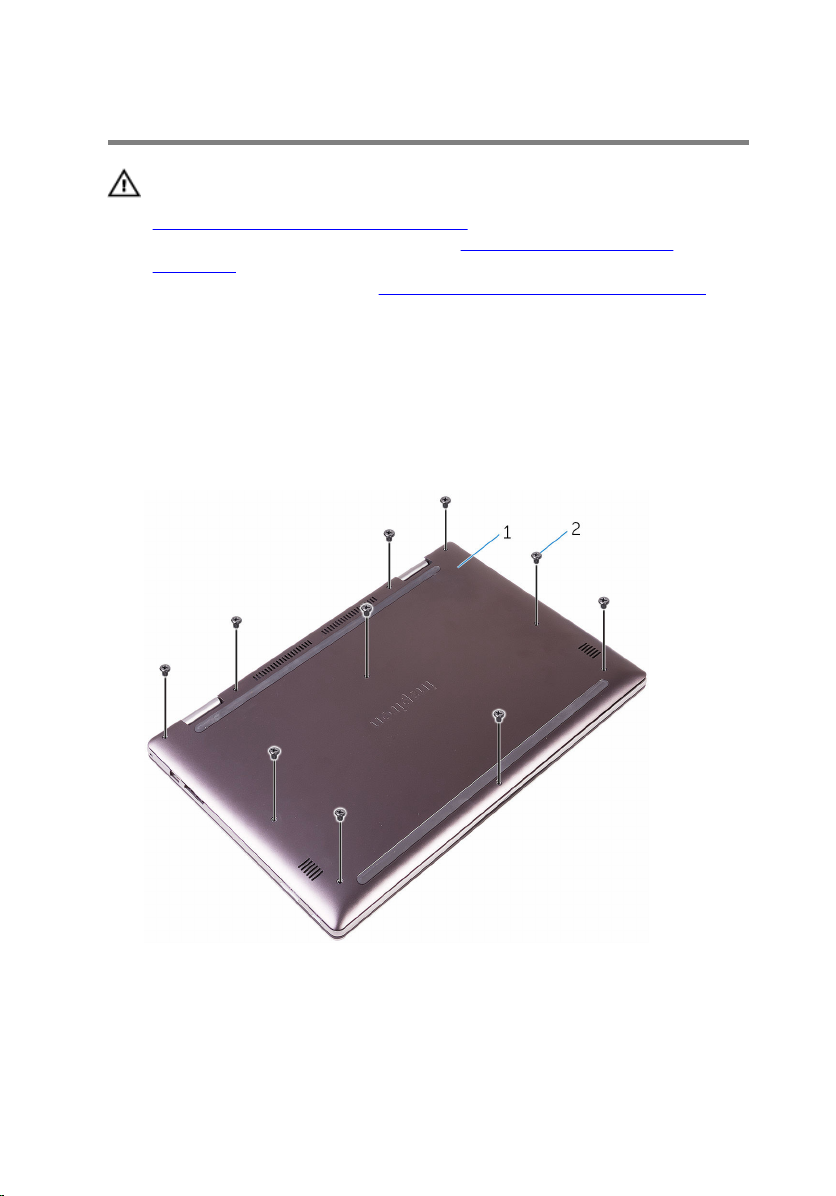
1 Close the display and turn the computer over.
2 Remove the screws that secure the base cover to the palm-rest
assembly.
www.dell.com/regulatory_compliance.
16
1 base cover 2 screws (10)
Page 17
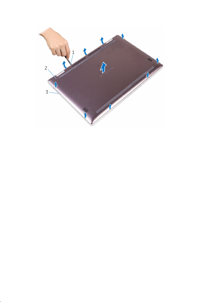
3 Using a plastic scribe, pry the base cover off the palm-rest assembly.
1 plastic scribe 2 base cover
3 palm-rest assembly
17
Page 18

Replacing the base cover
WARNING: Before working inside your computer, read the safety
information that shipped with your computer and follow the steps in
Before working inside your computer. After working inside your
computer, follow the instructions in After working inside your
computer. For more safety best practices, see the Regulatory
Compliance home page at
Procedure
1 Slide the tabs on the base cover into the slots on the palm-rest assembly
and snap the base cover into place.
2 Replace the screws that secure the base cover to the palm-rest assembly.
www.dell.com/regulatory_compliance.
18
Page 19

Removing the battery
WARNING: Before working inside your computer, read the safety
information that shipped with your computer and follow the steps in
Before working inside your computer. After working inside your
computer, follow the instructions in After working inside your
computer. For more safety best practices, see the Regulatory
Compliance home page at
Prerequisites
Remove the base cover.
Procedure
1 Disconnect the battery cable from the system board.
2 Remove the screws that secure the battery to the palm-rest assembly.
www.dell.com/regulatory_compliance.
19
Page 20
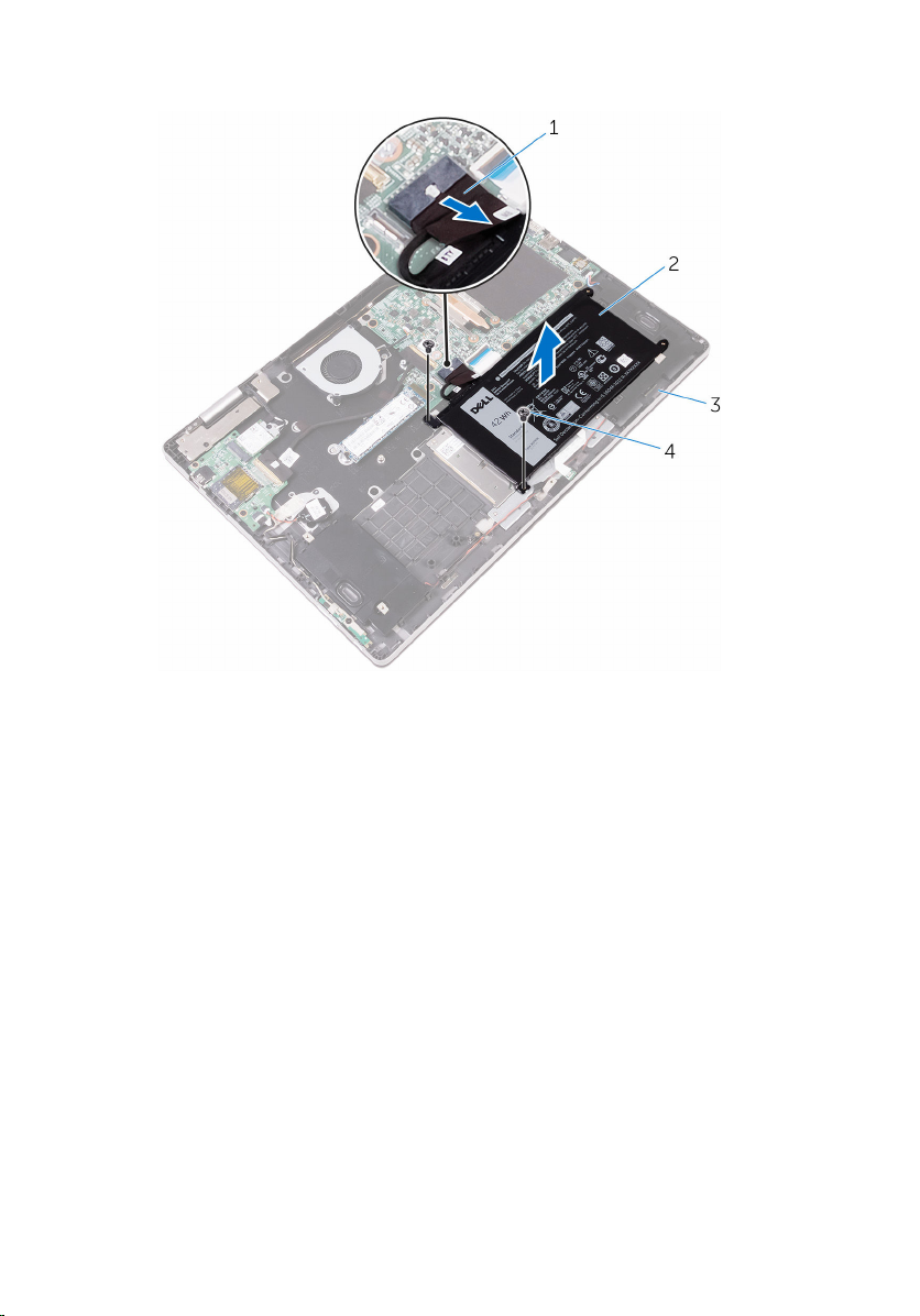
3 Lift the battery along with the battery cable off the palm-rest assembly.
1 battery cable 2 battery
3 palm-rest assembly 4 screws (2)
4 Press and hold the power button for 5 seconds to ground the system
board.
20
Page 21

Replacing the battery
WARNING: Before working inside your computer, read the safety
information that shipped with your computer and follow the steps in
Before working inside your computer. After working inside your
computer, follow the instructions in After working inside your
computer. For more safety best practices, see the Regulatory
Compliance home page at
Procedure
1 Align the screw holes on the battery with the screw holes on the palm-
rest assembly.
2 Replace the screws that secure the battery to the palm-rest assembly.
3 Connect the battery cable to the system board.
Post-requisites
Replace the base cover.
www.dell.com/regulatory_compliance.
21
Page 22

Removing the memory module
WARNING: Before working inside your computer, read the safety
information that shipped with your computer and follow the steps in
Before working inside your computer. After working inside your
computer, follow the instructions in After working inside your
computer. For more safety best practices, see the Regulatory
Compliance home page at
Prerequisites
1 Remove the base cover.
2 Remove the battery.
www.dell.com/regulatory_compliance.
22
Page 23
Procedure
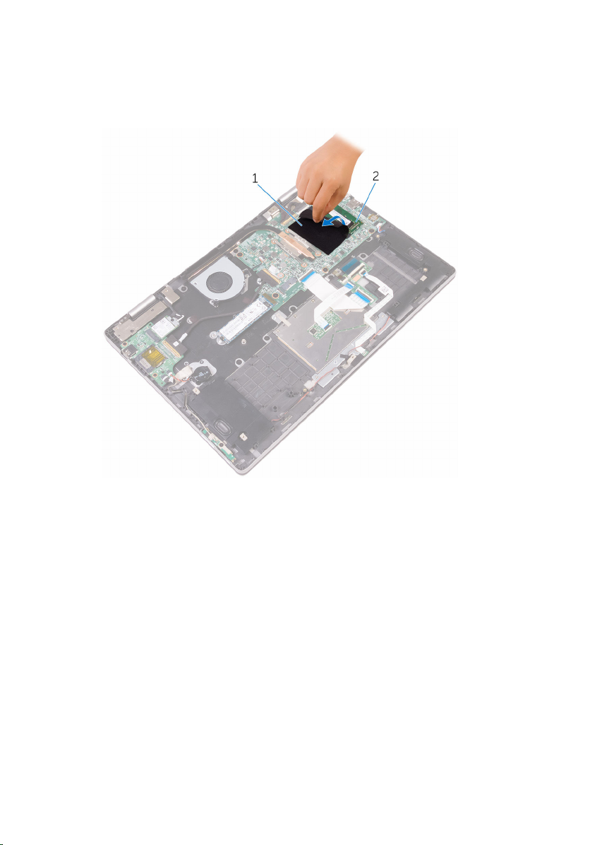
1 Lift the Mylar to access the memory module.
1 Mylar 2 memory module
2 Use your fingertips to carefully spread apart the securing-clips on each
end of the memory-module slot until the memory module pops up.
23
Page 24
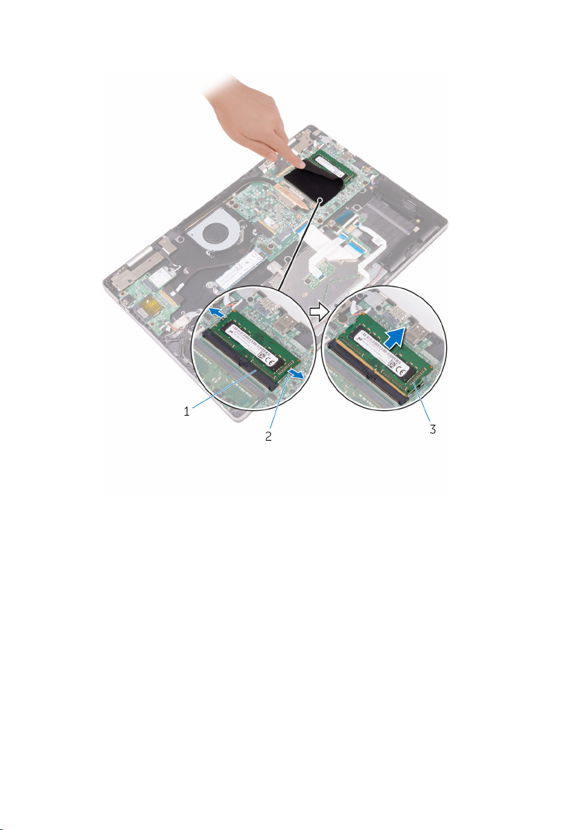
3 Remove the memory module from the memory-module slot.
24
1 memory-module slot 2 securing clips (2)
3 memory module
Page 25

Replacing the memory module
WARNING: Before working inside your computer, read the safety
information that shipped with your computer and follow the steps in
Before working inside your computer. After working inside your
computer, follow the instructions in After working inside your
computer. For more safety best practices, see the Regulatory
Compliance home page at
Procedure
1 Lift the Mylar to access the memory-module slot.
2 Align the notch on the memory module with the tab on the memory-
module slot.
www.dell.com/regulatory_compliance.
25
Page 26
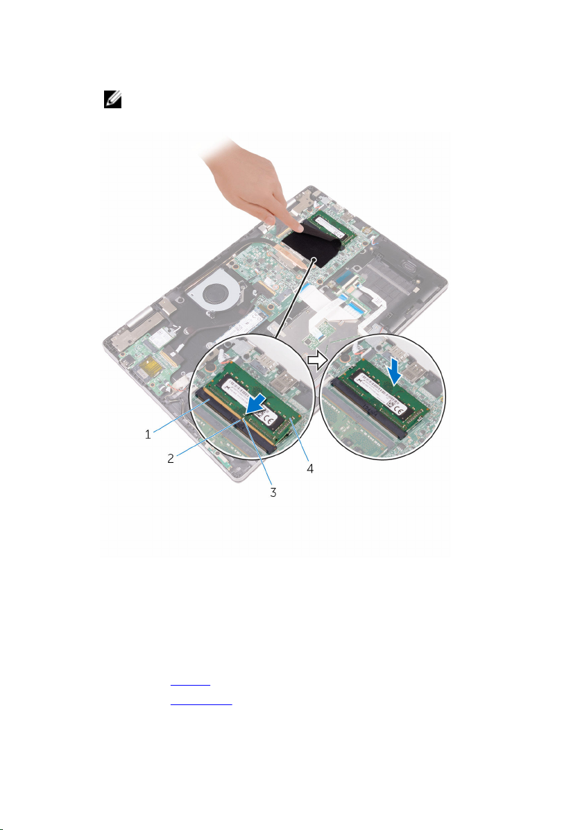
3 Slide the memory module firmly into the slot at an angle and press the
memory module down until it clicks into place.
NOTE: If you do not hear the click, remove the memory module
and reinstall it.
1 memory-module slot 2 tab
3 notch 4 memory module
Post-requisites
1 Replace the battery.
2 Replace the base cover.
26
Page 27

Removing the solid-state drive
WARNING: Before working inside your computer, read the safety
information that shipped with your computer and follow the steps in
Before working inside your computer. After working inside your
computer, follow the instructions in After working inside your
computer. For more safety best practices, see the Regulatory
Compliance home page at
CAUTION: Solid-state drives are fragile. Exercise care when handling
the solid-state drive.
CAUTION: To avoid data loss, do not remove the solid-state drive
while the computer is in sleep or on state.
Prerequisites
1 Remove the base cover.
2 Remove the battery.
Procedure
1 Remove the screw that secures the solid-state drive to the palm-rest
assembly.
www.dell.com/regulatory_compliance.
27
Page 28
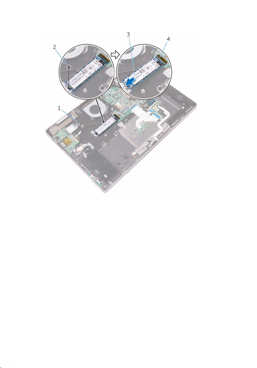
2 Remove the solid-state drive from the solid-state drive slot.
28
1 palm-rest assembly 2 screw
3 solid-state drive 4 solid-state drive slot
Page 29

Replacing the solid-state drive
WARNING: Before working inside your computer, read the safety
information that shipped with your computer and follow the steps in
Before working inside your computer. After working inside your
computer, follow the instructions in After working inside your
computer. For more safety best practices, see the Regulatory
Compliance home page at
CAUTION: Solid-state drives are fragile. Exercise care when handling
the solid-state drive.
Procedure
1 Align the notch on the solid-state drive with the tab on the solid-state
drive slot.
2 Slide the solid-state drive firmly into the slot and align the screw hole on
the solid-state drive with the screw hole on the palm-rest assembly.
www.dell.com/regulatory_compliance.
29
Page 30
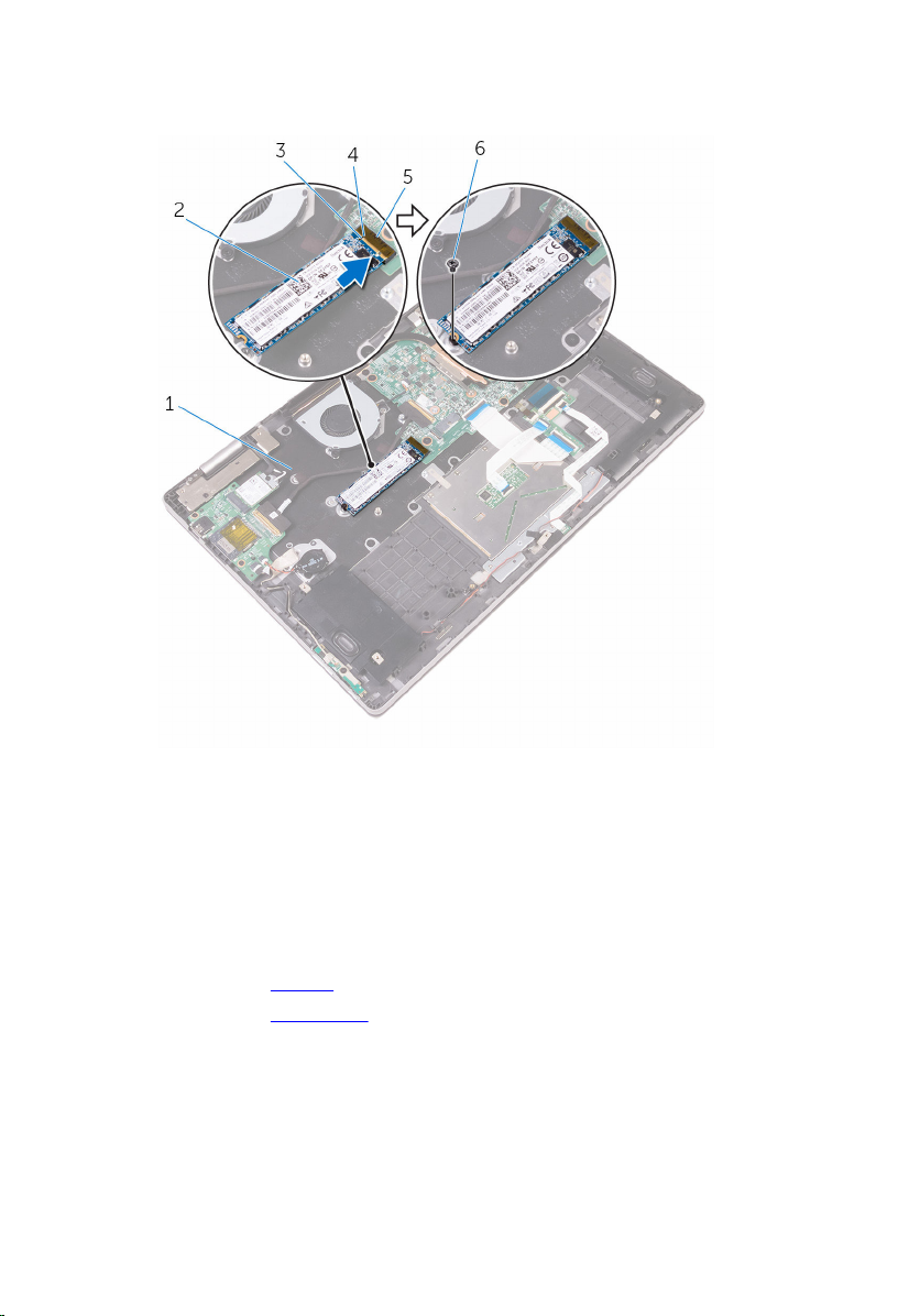
3 Replace the screw that secures the solid-state drive to the palm-rest
assembly.
1 palm-rest assembly 2 solid-state drive
3 notch 4 tab
5 solid-state drive slot 6 screw
Post-requisites
1 Replace the battery.
2 Replace the base cover.
30
Page 31

Removing the coin-cell battery
WARNING: Before working inside your computer, read the safety
information that shipped with your computer and follow the steps in
Before working inside your computer. After working inside your
computer, follow the instructions in After working inside your
computer. For more safety best practices, see the Regulatory
Compliance home page at www.dell.com/regulatory_compliance.
CAUTION: Removing the coin-cell battery resets the BIOS setup
program’s settings to default. It is recommended that you note the
BIOS setup program’s settings before removing the coin-cell battery.
Prerequisites
1 Remove the base cover.
2 Remove the battery.
Procedure
1 Disconnect the coin-cell battery cable from the I/O board.
31
Page 32

2 Peel the coin-cell battery off the palm-rest assembly.
1 coin-cell battery cable 2 coin-cell battery
3 I/O board 4 palm-rest assembly
32
Page 33

Replacing the coin-cell battery
WARNING: Before working inside your computer, read the safety
information that shipped with your computer and follow the steps in
Before working inside your computer. After working inside your
computer, follow the instructions in After working inside your
computer. For more safety best practices, see the Regulatory
Compliance home page at
Procedure
1 Connect the coin-cell battery cable to the I/O board.
2 Adhere the coin-cell battery to the palm-rest assembly.
Post-requisites
1 Replace the battery.
2 Replace the base cover.
www.dell.com/regulatory_compliance.
33
Page 34

Removing the wireless card
WARNING: Before working inside your computer, read the safety
information that shipped with your computer and follow the steps in
Before working inside your computer. After working inside your
computer, follow the instructions in After working inside your
computer. For more safety best practices, see the Regulatory
Compliance home page at
Prerequisites
1 Remove the base cover.
2 Remove the battery.
Procedure
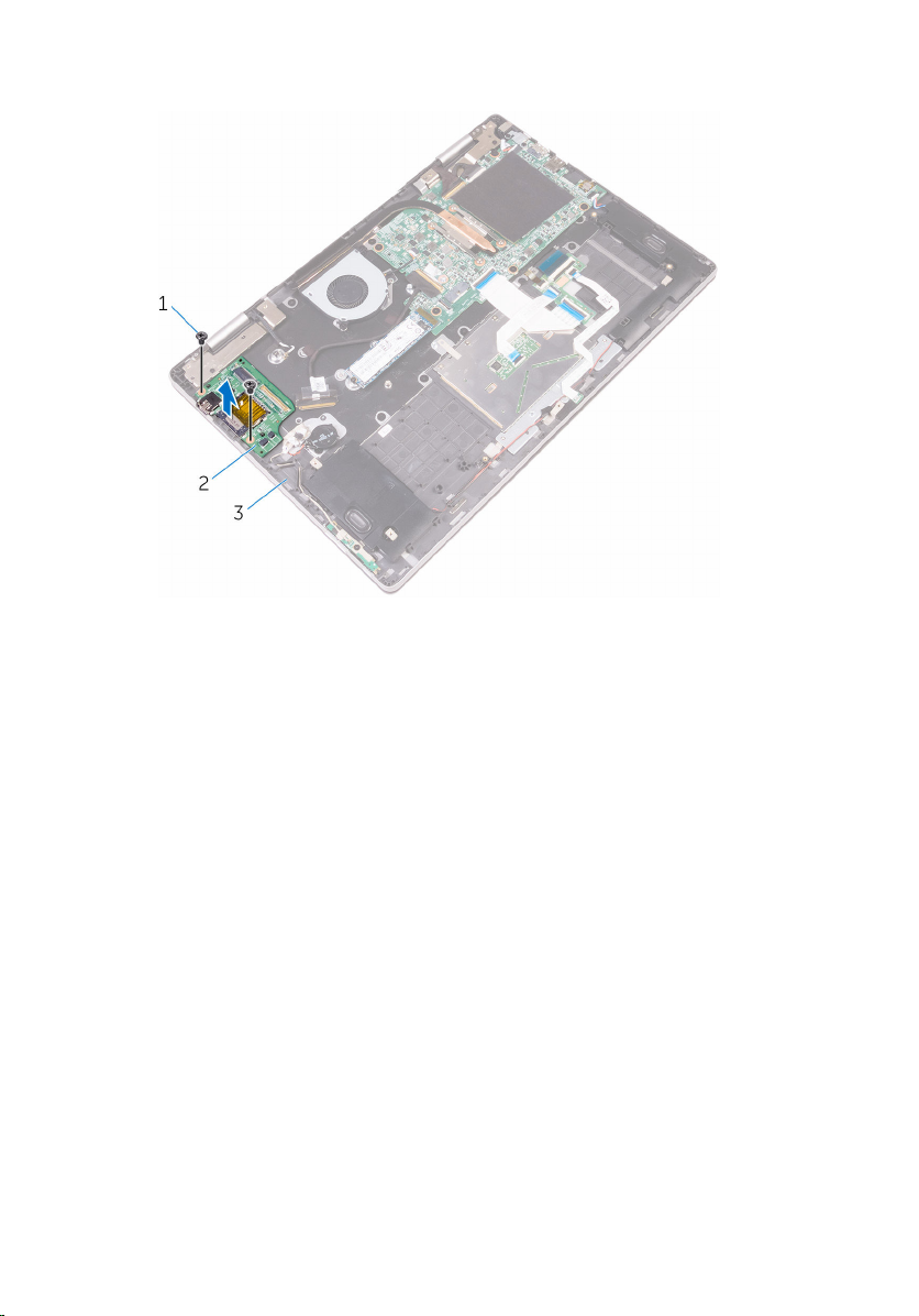
1 Remove the screw that secures the wireless-card bracket to the wireless
card and the palm-rest assembly.
2 Remove the wireless-card bracket and disconnect the antenna cables
from the wireless card.
www.dell.com/regulatory_compliance.
34
Page 35

3 Slide and remove the wireless card from the wireless-card slot.
1 wireless-card bracket 2 screw
3 antenna cables (2) 4 wireless-card slot
5 wireless card
35
Page 36

Replacing the wireless card
WARNING: Before working inside your computer, read the safety
information that shipped with your computer and follow the steps in
Before working inside your computer. After working inside your
computer, follow the instructions in After working inside your
computer. For more safety best practices, see the Regulatory
Compliance home page at
Procedure
CAUTION: To avoid any damages to the wireless card, do not place
any cables under it.
1 Align the notch on the wireless card with the tab on the wireless-card
slot.
2 Insert the wireless card at an angle into the wireless-card slot.
3 Connect the antenna cables to the wireless card.
The following table provides the antenna-cable color scheme for the
wireless card supported by your computer.
Connectors on the wireless card Antenna-cable color
Main (white triangle) White
www.dell.com/regulatory_compliance.
Auxiliary (black triangle) Black
4 Align the screw hole on the wireless-card bracket with the screw hole on
the wireless card and the palm-rest assembly.
36
Page 37

5 Replace the screw that secures the wireless-card bracket to the wireless
card and the palm-rest assembly.
1 tab 2 notch
3 wireless card 4 antenna cables (2)
5 screw 6 wireless-card bracket
7 wireless-card slot
Post-requisites
1 Replace the battery.
2 Replace the base cover.
37
Page 38

Removing the keyboard daughter-board
WARNING: Before working inside your computer, read the safety
information that shipped with your computer and follow the steps in
Before working inside your computer. After working inside your
computer, follow the instructions in After working inside your
computer. For more safety best practices, see the Regulatory
Compliance home page at www.dell.com/regulatory_compliance.
Prerequisites
1 Remove the base cover.
2 Remove the battery.
Procedure
1 Open the latches and disconnect the keyboard cables, keyboard-
backlight cable, status-light board cable, and the touch-pad cable from
the keyboard daughter-board.
38
Page 39

2 Using a plastic scribe, gently pry out the keyboard daughter-board from
the palm-rest assembly.
1 keyboard cable 2 touch-pad cable
3 keyboard-backlight cable 4 keyboard cable
5 latches (5) 6 status-light board cable
7 plastic scribe 8 keyboard daughter-board
39
Page 40

Replacing the keyboard daughter-board
WARNING: Before working inside your computer, read the safety
information that shipped with your computer and follow the steps in
Before working inside your computer. After working inside your
computer, follow the instructions in After working inside your
computer. For more safety best practices, see the Regulatory
Compliance home page at www.dell.com/regulatory_compliance.
Procedure
1 Adhere the keyboard daughter-board to the palm-rest assembly.
2 Slide the keyboard cables, keyboard-backlight cable, status-light board
cable, and the touch-pad cable into their respective connectors on the
keyboard daughter-board, and then close the latches to secure the
cables.
Post-requisites
1 Replace the battery.
2 Replace the base cover.
40
Page 41

Removing the status-light board
WARNING: Before working inside your computer, read the safety
information that shipped with your computer and follow the steps in
Before working inside your computer. After working inside your
computer, follow the instructions in After working inside your
computer. For more safety best practices, see the Regulatory
Compliance home page at www.dell.com/regulatory_compliance.
Prerequisites
1 Remove the base cover.
2 Remove the battery.
Procedure
1 Open the latch and disconnect the status-light board cable from the
keyboard daughter-board.
2 Peel off the tape that secures the speaker cable to the palm-rest
assembly.
41
Page 42

3 Note the speaker cable routing and remove the speaker cable from the
routing guides on the palm-rest assembly.
1 latch 2 status-light board cable
3 palm-rest assembly 4 speaker cable
5 tape 6 routing guides (3)
4 Peel off the foam that secures the status-light board to the palm-rest
assembly.
5 Peel off the status-light board cable from the palm-rest assembly.
42
Page 43

6 Lift the status-light board along with its cable off the palm-rest assembly.
1 status-light board cable 2 palm-rest assembly
3 status-light board 4 foam
43
Page 44

Replacing the status-light board
WARNING: Before working inside your computer, read the safety
information that shipped with your computer and follow the steps in
Before working inside your computer. After working inside your
computer, follow the instructions in After working inside your
computer. For more safety best practices, see the Regulatory
Compliance home page at www.dell.com/regulatory_compliance.
Procedure
1 Place the status-light board into the slot on the palm-rest assembly.
2 Adhere the foam that secures the status-light board to the palm-rest
assembly.
3 Slide the status-light board cable into the connector on the keyboard
daughter-board and close the latch to secure the cable.
4 Adhere the foam that secures the status-light board to the palm-rest
assembly.
5 Adhere the status-light board cable to the palm-rest assembly.
6 Route the speaker cable through the routing guides on the palm-rest
assembly and adhere the tape that secures the speaker cable to the
palm-rest assembly.
Post-requisites
1 Replace the battery.
2 Replace the base cover.
44
Page 45

Removing the touch pad
WARNING: Before working inside your computer, read the safety
information that shipped with your computer and follow the steps in
Before working inside your computer. After working inside your
computer, follow the instructions in After working inside your
computer. For more safety best practices, see the Regulatory
Compliance home page at
Prerequisites
1 Remove the base cover.
2 Remove the battery.
3 Remove the status-light board.
www.dell.com/regulatory_compliance.
45
Page 46

Procedure
1 Open the latches, and then disconnect the touch-pad cable from the
keyboard daughter-board and the touch pad.
46
1 latches (2) 2 touch-pad cable
3 keyboard daughter-board 4 touch pad
Page 47

2 Open the latches, and then disconnect the keyboard cable from the
keyboard daughter-board and the system board.
1 latches (2) 2 keyboard cable
3 keyboard daughter-board
3 Remove the screws that secure the touch-pad bracket to the palm-rest
assembly.
47
Page 48

4 Lift the touch-pad bracket off the palm-rest assembly.
1 screws (3) 2 touch-pad bracket
3 palm-rest assembly
5 Peel off the pieces of tape that secure the touch pad to the palm-rest
assembly.
6 Remove the screws that secure the touch pad to the palm-rest assembly.
48
Page 49

7 Lift the touch pad off the palm-rest assembly.
1 screws (3) 2 tape (2)
3 touch pad 4 palm-rest assembly
49
Page 50

Replacing the touch pad
WARNING: Before working inside your computer, read the safety
information that shipped with your computer and follow the steps in
Before working inside your computer. After working inside your
computer, follow the instructions in After working inside your
computer. For more safety best practices, see the Regulatory
Compliance home page at
Procedure
1 Align the screw holes on the touch pad with the screw holes on the
palm-rest assembly.
2 Replace the screws that secure the touch pad to the palm-rest assembly.
3 Adhere the pieces of tape that secure the touch pad to the palm-rest
assembly.
4 Align the screw holes on the touch-pad bracket with the screw holes on
the palm-rest assembly.
5 Replace the screws that secure the touch-pad bracket to the palm-rest
assembly.
6 Slide both ends of the keyboard cable into their respective connectors
and close the latches to secure the cable.
7 Slide both ends of the touch-pad cable into their respective connectors
and close the latches to secure the cable.
www.dell.com/regulatory_compliance.
Post-requisites
1 Replace the status-light board.
2 Replace the battery.
3 Replace the base cover.
50
Page 51

Removing the speakers
WARNING: Before working inside your computer, read the safety
information that shipped with your computer and follow the steps in
Before working inside your computer. After working inside your
computer, follow the instructions in After working inside your
computer. For more safety best practices, see the Regulatory
Compliance home page at
Prerequisites
1 Remove the base cover.
2 Remove the battery.
Procedure
1 Disconnect the speaker cable from the system board.
2 Remove the speaker cable from the routing guides on the palm-rest
assembly.
www.dell.com/regulatory_compliance.
51
Page 52

3 Peel off the tape that secures the speaker cable to the touch-pad
bracket.
1 system board 2 speaker cable
3 palm-rest assembly 4 routing guides (3)
5 tape
4 Using a plastic scribe, pry up the speakers to release the tabs on the
speakers from the slots on the palm-rest assembly.
52
Page 53

5 Lift the speakers along with its cable off the palm-rest assembly.
1 plastic scribe 2 palm-rest assembly
3 tabs (8) 4 speakers (2)
53
Page 54

Replacing the speakers
WARNING: Before working inside your computer, read the safety
information that shipped with your computer and follow the steps in
Before working inside your computer. After working inside your
computer, follow the instructions in After working inside your
computer. For more safety best practices, see the Regulatory
Compliance home page at
Procedure
1 Using the alignment posts, place the speakers in the slots on the palm-
rest assembly and snap the speakers into place.
2 Route the speaker cable through the routing guides on the palm-rest
assembly.
3 Adhere the tape that secures the speaker cable to the touch-pad bracket.
4 Connect the speaker cable to the system board.
Post-requisites
1 Replace the battery.
2 Replace the base cover.
www.dell.com/regulatory_compliance.
54
Page 55

Removing the fan
WARNING: Before working inside your computer, read the safety
information that shipped with your computer and follow the steps in
Before working inside your computer. After working inside your
computer, follow the instructions in After working inside your
computer. For more safety best practices, see the Regulatory
Compliance home page at
Prerequisites
1 Remove the base cover.
2 Remove the battery.
Procedure
1 Disconnect the fan cable from the system board.
2 Remove the screws that secure the fan to the palm-rest assembly.
www.dell.com/regulatory_compliance.
55
Page 56

3 Lift the fan along with its cable off the palm-rest assembly.
1 fan cable 2 system board
56
3 screws (2) 4 fan
5 palm-rest assembly
Page 57

Replacing the fan
WARNING: Before working inside your computer, read the safety
information that shipped with your computer and follow the steps in
Before working inside your computer. After working inside your
computer, follow the instructions in After working inside your
computer. For more safety best practices, see the Regulatory
Compliance home page at
Procedure
1 Align the screw holes on the fan with the screw holes on the palm-rest
assembly.
2 Replace the screws that secure the fan to the palm-rest assembly.
3 Connect the fan cable to the system board.
Post-requisites
1 Replace the battery.
2 Replace the base cover.
www.dell.com/regulatory_compliance.
57
Page 58

Removing the heat sink
WARNING: Before working inside your computer, read the safety
information that shipped with your computer and follow the steps in
Before working inside your computer. After working inside your
computer, follow the instructions in After working inside your
computer. For more safety best practices, see the Regulatory
Compliance home page at
WARNING: The heat sink may become hot during normal operation.
Allow sufficient time for the heat sink to cool before you touch it.
CAUTION: For maximum cooling of the processor, do not touch the
heat transfer areas on the heat sink. The oils in your skin can reduce
the heat transfer capability of the thermal grease.
Prerequisites
1 Remove the base cover.
2 Remove the battery.
Procedure
1 In sequential order (as indicated on the heat sink), loosen the captive
screws that secure the heat sink to the system board.
www.dell.com/regulatory_compliance.
58
Page 59

2 Lift the heat sink off the system board.
1 captive screws (4) 2 system board
3 heat sink
59
Page 60

Replacing the heat sink
WARNING: Before working inside your computer, read the safety
information that shipped with your computer and follow the steps in
Before working inside your computer. After working inside your
computer, follow the instructions in After working inside your
computer. For more safety best practices, see the Regulatory
Compliance home page at
CAUTION: Incorrect alignment of the heat sink can damage the
system board and processor.
NOTE: The original thermal grease can be reused if the original system
board and heat sink are reinstalled together. If either the system board
or the heat sink is replaced, use the thermal pad provided in the kit to
ensure that thermal conductivity is achieved.
Procedure
1 Align the screw holes on the heat sink with the screw holes on the
system board.
2 In sequential order (indicated on the heat sink), tighten the captive screws
that secure the heat sink to the system board.
Post-requisites
www.dell.com/regulatory_compliance.
1 Replace the battery.
2 Replace the base cover.
60
Page 61

Removing the power-adapter port
WARNING: Before working inside your computer, read the safety
information that shipped with your computer and follow the steps in
Before working inside your computer. After working inside your
computer, follow the instructions in After working inside your
computer. For more safety best practices, see the Regulatory
Compliance home page at www.dell.com/regulatory_compliance.
Prerequisites
1 Remove the base cover.
2 Remove the battery.
Procedure
1 Disconnect the power-adapter port cable from the system board.
2 Remove the screw that secures the power-adapter port to the palm-rest
assembly.
61
Page 62

3 Lift the power-adapter port along with its cable off the palm-rest
assembly.
62
1 screw 2 power-adapter port
3 palm-rest assembly 4 power-adapter port cable
5 system board
Page 63

Replacing the power-adapter port
WARNING: Before working inside your computer, read the safety
information that shipped with your computer and follow the steps in
Before working inside your computer. After working inside your
computer, follow the instructions in After working inside your
computer. For more safety best practices, see the Regulatory
Compliance home page at www.dell.com/regulatory_compliance.
Procedure
1 Place the power-adapter port into the slot on the palm-rest assembly.
2 Align the screw hole on the power-adapter port with the screw hole on
the palm-rest assembly.
3 Replace the screw that secures the power-adapter port to the palm-rest
assembly.
4 Connect the power-adapter port cable to the system board.
Post-requisites
1 Replace the battery.
2 Replace the base cover.
63
Page 64

Removing the power and volume-buttons board
WARNING: Before working inside your computer, read the safety
information that shipped with your computer and follow the steps in
Before working inside your computer. After working inside your
computer, follow the instructions in After working inside your
computer. For more safety best practices, see the Regulatory
Compliance home page at www.dell.com/regulatory_compliance.
Prerequisites
1 Remove the base cover.
2 Remove the battery.
Procedure
1 Disconnect the coin-cell battery cable from the I/O board.
2 Peel off the tape that secures the power and volume-buttons board cable
to the palm-rest assembly.
3 Disconnect the power and volume-buttons board cable from the I/O
board.
4 Remove the power and volume-buttons board cable from the routing
guides on the palm-rest assembly.
5 Remove the screw that secures the power and volume-buttons board to
the palm-rest assembly.
64
Page 65

6 Lift the power and volume-buttons board along with its cable off the
palm-rest assembly.
1 coin-cell battery cable 2 power and volume-
buttons board cable
3 I/O board 4 routing guides
5 power and volume-buttons
board
7 palm-rest assembly
6 screw
65
Page 66

Replacing the power and volume-buttons board
WARNING: Before working inside your computer, read the safety
information that shipped with your computer and follow the steps in
Before working inside your computer. After working inside your
computer, follow the instructions in After working inside your
computer. For more safety best practices, see the Regulatory
Compliance home page at www.dell.com/regulatory_compliance.
Procedure
1 Align the screw hole on the power and volume-buttons board with the
screw hole on the palm-rest assembly.
2 Replace the screw that secures the power and volume-buttons board to
the palm-rest assembly.
3 Route the power and volume-buttons board cable through the routing
guides on the palm-rest assembly.
4 Connect the power and volume-buttons board cable to the I/O board.
5 Adhere the tape that secures the power and volume-buttons board cable
to the palm-rest assembly.
6 Connect the coin-cell battery cable to the I/O board.
Post-requisites
1 Replace the battery.
2 Replace the base cover.
66
Page 67

Removing the I/O board
WARNING: Before working inside your computer, read the safety
information that shipped with your computer and follow the steps in
Before working inside your computer. After working inside your
computer, follow the instructions in After working inside your
computer. For more safety best practices, see the Regulatory
Compliance home page at
Prerequisites
1 Remove the base cover.
2 Remove the battery.
3 Remove the wireless card.
Procedure
1 Peel off the tape that secures the I/O-board cable to the I/O board.
2 Open the latch and disconnect the I/O-board cable from the I/O board.
www.dell.com/regulatory_compliance.
67
Page 68

3 Disconnect the coin-cell battery cable and the power and volume-
buttons board cable from the I/O board.
1 I/O-board cable 2 tape
3 latch 4 I/O board
5 coin-cell battery cable 6 power and volume-
buttons board cable
4 Remove the screws that secure the I/O board to the palm-rest assembly.
68
Page 69
5 Lift the I/O board off the palm-rest assembly.
1 screws (2) 2 I/O board
3 palm-rest assembly
69
Page 70

Replacing the I/O board
WARNING: Before working inside your computer, read the safety
information that shipped with your computer and follow the steps in
Before working inside your computer. After working inside your
computer, follow the instructions in After working inside your
computer. For more safety best practices, see the Regulatory
Compliance home page at
Procedure
1 Using the alignment posts, place the I/O board on the palm-rest
assembly.
2 Align the screw holes on the I/O board with the screw holes on the palm-
rest assembly.
3 Replace the screws that secure the I/O board to the palm-rest assembly.
4 Connect the power and volume-buttons board cable and the coin-cell
battery cable to the I/O board.
5 Slide the I/O-board cable into the connector on the I/O board and close
the latch to secure the cable.
6 Adhere the tape that secures the I/O-board cable to the I/O board.
Post-requisites
www.dell.com/regulatory_compliance.
1 Replace the wireless card.
2 Replace the battery.
3 Replace the base cover.
70
Page 71

Removing the system board
WARNING: Before working inside your computer, read the safety
information that shipped with your computer and follow the steps in
Before working inside your computer. After working inside your
computer, follow the instructions in After working inside your
computer. For more safety best practices, see the Regulatory
Compliance home page at
NOTE: Your computer’s Service Tag is stored in the system board. You
must enter the Service Tag in the BIOS setup program after you replace
the system board.
NOTE: Replacing the system board removes any changes you have
made to the BIOS using the BIOS setup program. You must make the
appropriate changes again after you replace the system board.
NOTE: Before disconnecting the cables from the system board, note the
location of the connectors so that you can reconnect the cables
correctly after you replace the system board.
Prerequisites
1 Remove the base cover.
2 Remove the battery.
3 Remove the solid-state drive.
4 Remove the memory module.
5 Remove the heat sink.
www.dell.com/regulatory_compliance.
Procedure
1 Disconnect the fan cable and the power-adapter port cable from the
system board.
2 Peel off the pieces of tape that secure the display cable and touch-screen
board cable from their respective connectors.
71
Page 72

3 Open the latches and disconnect the display cable and the touch-screen
board cable from the system board.
1 fan cable 2 latches (2)
3 display cable 4 touch-screen board cable
5 power-adapter port cable 6 system board
4 Disconnect the speaker cable from the system board.
72
Page 73

5 Open the latches and disconnect the keyboard cable and the I/O-board
cable from the system board.
1 speaker cable 2 system board
3 latches (2) 4 keyboard cable
5 I/O-board cable
6 Remove the screws that secure the I/O bracket to the system board and
the palm-rest assembly.
7 Remove the screws that secure the system board to the palm-rest
assembly.
73
Page 74

8 Lift the system board off the palm-rest assembly.
74
1 screws (7) 2 I/O bracket
3 system board 4 palm-rest assembly
Page 75
Replacing the system board
WARNING: Before working inside your computer, read the safety
information that shipped with your computer and follow the steps in
Before working inside your computer. After working inside your
computer, follow the instructions in After working inside your
computer. For more safety best practices, see the Regulatory
Compliance home page at
NOTE: Your computer’s Service Tag is stored in the system board. You
must enter the Service Tag in the BIOS setup program after you replace
the system board.
NOTE: Replacing the system board removes any changes you have
made to the BIOS using the BIOS setup program. You must make the
appropriate changes again after you replace the system board.
Procedure
1 Align the screw holes on the system board with the screw holes on the
palm-rest assembly.
2 Replace the screws that secure the system board to the palm-rest
assembly.
3 Align the screw holes on the I/O bracket with the screw holes on the
system board and palm-rest assembly.
4 Replace the screws that secure the I/O bracket to the system board and
palm-rest assembly.
5 Connect the fan cable, power-adapter port cable, and speaker cable to
the system board.
6 Slide the keyboard cable and the I/O-board cable into their respective
connectors on the system board, and then close the latches to secure
the cables.
7 Slide the display cable and the touch-screen board cable into their
respective connectors on the system board, and then close the latches to
secure the cables.
8 Adhere the pieces of tape that secure the display cable and the touch-
screen board cable to their respective connectors on the system board.
www.dell.com/regulatory_compliance.
75
Page 76

Post-requisites
1 Replace the heat sink.
2 Replace the solid-state drive.
3 Replace the memory module.
4 Replace the battery.
5 Replace the base cover.
Entering the Service Tag in the BIOS setup program
1 Turn on or restart your computer.
2 Press F2 when the Dell logo is displayed to enter the BIOS setup program.
3 Navigate to the Main tab and enter the Service Tag in the Service Tag
Input field.
76
Page 77

Removing the display assembly
WARNING: Before working inside your computer, read the safety
information that shipped with your computer and follow the steps in
Before working inside your computer. After working inside your
computer, follow the instructions in After working inside your
computer. For more safety best practices, see the Regulatory
Compliance home page at www.dell.com/regulatory_compliance.
Prerequisites
1 Remove the base cover.
2 Remove the battery.
3 Remove the wireless card.
4 Remove the solid-state drive.
5 Remove the memory module.
6 Remove the heat sink.
7 Remove the system board.
77
Page 78

Procedure
1 Turn the computer over and open the display to 180-degree angle.
CAUTION: Place the computer on a soft and clean surface to avoid
scratching the display.
1 palm-rest assembly 2 display assembly
2 Place the computer on a flat surface with the display facing down.
3 Remove the screws that secure the display assembly to the palm-rest
assembly.
78
Page 79

4 Lift the display assembly off the palm-rest assembly.
1 display assembly 2 screws (2)
3 display hinges (2) 4 palm-rest assembly
79
Page 80

Replacing the display assembly
WARNING: Before working inside your computer, read the safety
information that shipped with your computer and follow the steps in
Before working inside your computer. After working inside your
computer, follow the instructions in After working inside your
computer. For more safety best practices, see the Regulatory
Compliance home page at
Procedure
CAUTION: Place the computer on a soft and clean surface to avoid
scratching the display.
1 With the display facing down, align the screw holes on the display hinges
with the screw holes on the palm-rest assembly.
2 Replace the screws that secure the display assembly to the palm-rest
assembly.
3 Turn the computer over and close the display.
Post-requisites
1 Replace the system board.
2 Replace the heat sink.
3 Replace the solid-state drive.
4 Replace the memory module.
5 Replace the wireless card.
6 Replace the battery.
7 Replace the base cover.
www.dell.com/regulatory_compliance.
80
Page 81

Removing the keyboard
WARNING: Before working inside your computer, read the safety
information that shipped with your computer and follow the steps in
Before working inside your computer. After working inside your
computer, follow the instructions in After working inside your
computer. For more safety best practices, see the Regulatory
Compliance home page at
Prerequisites
1 Remove the base cover.
2 Remove the battery.
3 Remove the memory module.
4 Remove the wireless card.
5 Remove the coin-cell battery.
6 Remove the solid-state drive.
7 Remove the fan.
8 Remove the heat sink.
9 Remove the I/O board.
10 Remove the system board.
11 Remove the display assembly.
www.dell.com/regulatory_compliance.
Procedure
1 Remove the screws that secure the keyboard bracket to the palm-rest
assembly.
81
Page 82

2 Lift the keyboard bracket off the keyboard.
1 screws (16) 2 keyboard bracket
3 palm-rest assembly
3 Open the latches and disconnect the keyboard cable and keyboard-
backlight cable from the keyboard daughter-board.
4 Remove the screws that secure the keyboard assembly to the palm-rest
assembly.
82
Page 83

5 Lift the keyboard along with its cables off the palm-rest assembly.
1 screws (11) 2 keyboard
3 keyboard cable 4 latch
5 keyboard daughter-board 6 keyboard-backlight cable
83
Page 84

Replacing the keyboard
WARNING: Before working inside your computer, read the safety
information that shipped with your computer and follow the steps in
Before working inside your computer. After working inside your
computer, follow the instructions in After working inside your
computer. For more safety best practices, see the Regulatory
Compliance home page at
Procedure
1 Align the screw holes on the keyboard with the screw holes on the palm-
rest assembly.
2 Slide the keyboard cable and the keyboard-backlight cable into the
respective connectors and press down the latches to secure the cables.
3 Replace the screws that secure the keyboard to the palm-rest assembly.
4 Align the screw holes on the keyboard bracket with the screw holes on
the palm-rest assembly.
5 Replace the screws that secure the keyboard bracket to the palm-rest
assembly.
Post-requisites
www.dell.com/regulatory_compliance.
1 Replace the display assembly.
2 Replace the system board.
3 Replace the I/O board.
4 Replace the heat sink.
5 Replace the fan.
6 Replace the solid-state drive.
7 Replace the coin-cell battery.
8 Replace the wireless card.
9 Replace the memory module.
10 Replace the battery.
11 Replace the base cover.
84
Page 85

Removing the palm rest
WARNING: Before working inside your computer, read the safety
information that shipped with your computer and follow the steps in
Before working inside your computer. After working inside your
computer, follow the instructions in After working inside your
computer. For more safety best practices, see the Regulatory
Compliance home page at
Prerequisites
1 Remove the base cover.
2 Remove the battery.
3 Remove the memory module.
4 Remove the wireless card.
5 Remove the coin-cell battery.
6 Remove the solid-state drive.
7 Remove the keyboard daughter-board.
8 Remove the status-light board.
9 Remove the touch pad.
10 Remove the speakers.
11 Remove the fan.
12 Remove the heat sink.
13 Remove the I/O board.
14 Remove the power and volume-buttons board.
15 Remove the power-adapter port.
16 Remove the system board.
17 Remove the display assembly.
18 Remove the keyboard.
www.dell.com/regulatory_compliance.
Procedure
After performing the steps in prerequisites, we are left with the palm rest.
85
Page 86

1 palm rest
86
Page 87

Replacing the palm rest
WARNING: Before working inside your computer, read the safety
information that shipped with your computer and follow the steps in
Before working inside your computer. After working inside your
computer, follow the instructions in After working inside your
computer. For more safety best practices, see the Regulatory
Compliance home page at
Procedure
Place the palm rest on a clean and flat surface.
Post-requisites
1 Replace the keyboard.
2 Replace the display assembly.
3 Replace the system board.
4 Replace the power-adapter port.
5 Replace the power and volume-buttons board.
6 Replace the I/O board.
7 Replace the heat sink.
8 Replace the fan.
9 Replace the speakers.
10 Replace the touch pad.
11 Replace the status-light board.
12 Replace the keyboard daughter-board.
13 Replace the solid-state drive.
14 Replace the coin-cell battery.
15 Replace the wireless card.
16 Replace the memory module.
17 Replace the battery.
18 Replace the base cover.
www.dell.com/regulatory_compliance.
87
Page 88

Removing the display panel
WARNING: Before working inside your computer, read the safety
information that shipped with your computer and follow the steps in
Before working inside your computer. After working inside your
computer, follow the instructions in After working inside your
computer. For more safety best practices, see the Regulatory
Compliance home page at
Prerequisites
1 Remove the base cover.
2 Remove the battery.
3 Remove the display assembly.
Procedure
1 Remove the display cable from inside the hinge covers.
www.dell.com/regulatory_compliance.
88
Page 89

2 Using a plastic scribe, pry up the display-panel assembly to release the
tabs that secure display-panel assembly to the display back-cover and
antenna assembly.
1 display-panel assembly 2 plastic scribe
3 hinge covers (2) 4 display cable
5 display back-cover and
antenna assembly
3 Remove the camera.
4 Remove the sensor board.
89
Page 90

5 Remove the display cable.
After performing the preceding steps, we are left with the display panel.
1 display panel
90
Page 91

Replacing the display panel
WARNING: Before working inside your computer, read the safety
information that shipped with your computer and follow the steps in
Before working inside your computer. After working inside your
computer, follow the instructions in After working inside your
computer. For more safety best practices, see the Regulatory
Compliance home page at
Procedure
CAUTION: Place the display panel on a soft and clean surface to avoid
scratching the display.
1 Place the display panel on a flat surface with the display facing down.
2 Replace the display cable.
3 Replace the sensor board.
4 Replace the camera.
5 Turn over the display-panel assembly.
6 Align the display-panel assembly with the display back-cover and
antenna assembly and gently snap the display-panel assembly into place.
Post-requisites
www.dell.com/regulatory_compliance.
1 Replace the display assembly.
2 Replace the battery.
3 Replace the base cover.
91
Page 92

Removing the display cable
WARNING: Before working inside your computer, read the safety
information that shipped with your computer and follow the steps in
Before working inside your computer. After working inside your
computer, follow the instructions in After working inside your
computer. For more safety best practices, see the Regulatory
Compliance home page at
Prerequisites
1 Remove the base cover.
2 Remove the battery.
3 Remove the display assembly.
4 Follow the procedure from step 1 to step 2 in “Removing the display
panel”.
5 Remove the camera.
Procedure
1 Peel off the tape on the sensor-board connector.
www.dell.com/regulatory_compliance.
92
Page 93
2 Open the latch and disconnect the sensor-board cable from the sensor
board.
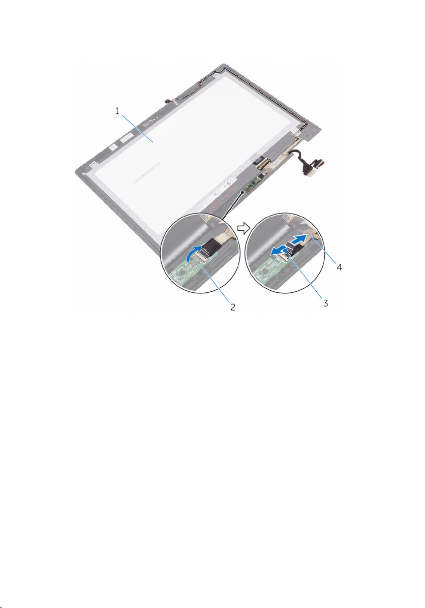
1 display panel 2 tape
3 latch 4 sensor-board cable
3 Peel off the tape on the display-cable connector.
4 Open the latch and disconnect the display cable from the display panel.
5 Note the display cable routing and remove the display cable from the
routing guides on the display-panel assembly.
6 Peel off the tape that secures the display cable from the display-panel
assembly.
93
Page 94

7 Lift the display cable off the display-panel assembly.
1 tape 2 display-panel assembly
3 latch 4 display cable
94
5 tape
Page 95

Replacing the display cable
WARNING: Before working inside your computer, read the safety
information that shipped with your computer and follow the steps in
Before working inside your computer. After working inside your
computer, follow the instructions in After working inside your
computer. For more safety best practices, see the Regulatory
Compliance home page at
Procedure
1 Adhere the tape that secures the display cable to the display-panel
assembly.
2 Route the display cable through the routing guides on the display-panel
assembly.
3 Slide the display cable into the connector on the display panel and close
the latch to secure the cable.
4 Adhere the tape on the display-cable connector.
5 Slide the sensor-board cable into the connector on the sensor board and
close the latch to secure the cable.
6 Adhere the tape on the sensor-board connector.
Post-requisites
www.dell.com/regulatory_compliance.
1 Replace the camera.
2 Follow the procedure from step 5 to step 6 in “Replacing the display
panel”.
3 Replace the display assembly.
4 Replace the battery.
5 Replace the base cover.
95
Page 96

Removing the display backcover and antenna assembly
WARNING: Before working inside your computer, read the safety
information that shipped with your computer and follow the steps in
Before working inside your computer. After working inside your
computer, follow the instructions in After working inside your
computer. For more safety best practices, see the Regulatory
Compliance home page at www.dell.com/regulatory_compliance.
Prerequisites
1 Remove the base cover.
2 Remove the battery.
3 Remove the display assembly.
4 Follow the procedure from step 1 to step 2 in “Removing the display
panel”.
Procedure
After performing the steps in prerequisites, we are left with the display backcover and antenna assembly.
96
Page 97

1 display back-cover and antenna
assembly
2 antenna cables
97
Page 98

Replacing the display backcover and antenna assembly
WARNING: Before working inside your computer, read the safety
information that shipped with your computer and follow the steps in
Before working inside your computer. After working inside your
computer, follow the instructions in After working inside your
computer. For more safety best practices, see the Regulatory
Compliance home page at www.dell.com/regulatory_compliance.
Procedure
Place the display back-cover and antenna assembly on a flat surface.
Post-requisites
1 Follow the procedure from step 5 to step 6 in “Replacing the display
panel”.
2 Replace the display assembly.
3 Replace the battery.
4 Replace the base cover.
98
Page 99

Removing the camera
WARNING: Before working inside your computer, read the safety
information that shipped with your computer and follow the steps in
Before working inside your computer. After working inside your
computer, follow the instructions in After working inside your
computer. For more safety best practices, see the Regulatory
Compliance home page at
Prerequisites
1 Remove the base cover.
2 Remove the battery.
3 Remove the display assembly.
4 Follow the procedure from step 1 to step 2 in “Removing the display
panel”.
Procedure
CAUTION: Place the display-panel assembly on a soft and clean
surface to avoid scratching the display.
1 Place the display-panel assembly on a flat surface with the display facing
down.
2 Using a plastic scribe, pry the camera module off the display-panel
assembly.
www.dell.com/regulatory_compliance.
99
Page 100

3 Turn the camera over and disconnect the display cable from the camera
module.
100
1 camera module 2 plastic scribe
3 display cable 4 display-panel assembly
 Loading...