

Page 1

Inspiron 13 5000
Service Manual
Computer Model: Inspiron 5370
Regulatory Model: P87G
Regulatory Type: P87G001
Page 2

Notes, cautions, and warnings
NOTE: A NOTE indicates important information that helps you make
better use of your product.
CAUTION: A CAUTION indicates either potential damage to hardware or
loss of data and tells you how to avoid the problem.
WARNING: A WARNING indicates a potential for property damage,
personal injury, or death.
Copyright © 2017 Dell Inc. or its subsidiaries. All rights reserved. Dell, EMC, and other
trademarks are trademarks of Dell Inc. or its subsidiaries. Other trademarks may be
trademarks of their respective owners.
2017 - 11
Rev. A00
Page 3

Contents
Before working inside your computer............................ 11
Before you begin ......................................................................................11
Safety instructions....................................................................................11
Recommended tools................................................................................ 12
Screw list................................................................................................. 13
After working inside your computer..............................15
Removing the base cover............................................. 16
Procedure................................................................................................16
Replacing the base cover.............................................20
Procedure............................................................................................... 20
Removing the battery................................................... 21
Prerequisites............................................................................................ 21
Procedure................................................................................................22
Replacing the battery...................................................24
Procedure................................................................................................24
Post-requisites........................................................................................ 24
Removing the memory module.....................................25
Prerequisites........................................................................................... 25
Procedure............................................................................................... 26
3
Page 4

Replacing the memory module.....................................28
Procedure................................................................................................28
Post-requisites........................................................................................ 29
Removing the wireless card......................................... 30
Prerequisites........................................................................................... 30
Procedure................................................................................................ 31
Replacing the wireless card..........................................33
Procedure................................................................................................33
Post-requisites........................................................................................ 34
Removing the coin-cell battery.................................... 35
Prerequisites........................................................................................... 35
Procedure............................................................................................... 35
Replacing the coin-cell battery.....................................37
Procedure................................................................................................37
Post-requisites.........................................................................................37
Removing the fan.........................................................38
Prerequisites............................................................................................38
Procedure............................................................................................... 38
Replacing the fan.........................................................40
Procedure............................................................................................... 40
Post-requisites........................................................................................ 40
Removing the solid-state drive..................................... 41
Prerequisites............................................................................................ 41
Procedure................................................................................................42
4
Page 5

Replacing the solid-state drive.....................................43
Procedure................................................................................................43
Post-requisites........................................................................................ 44
Removing the touchpad...............................................45
Prerequisites........................................................................................... 45
Procedure............................................................................................... 45
Replacing the touchpad............................................... 47
Procedure................................................................................................47
Post-requisites........................................................................................ 47
Removing the speakers................................................48
Prerequisites............................................................................................48
Procedure............................................................................................... 48
Replacing the speakers................................................50
Procedure............................................................................................... 50
Post-requisites........................................................................................ 50
Removing the heat sink................................................ 51
Prerequisites............................................................................................ 51
Procedure................................................................................................ 51
Replacing the heat sink................................................53
Procedure............................................................................................... 53
Post-requisites........................................................................................ 53
Removing the power-adapter port............................... 54
Prerequisites........................................................................................... 54
Procedure............................................................................................... 55
5
Page 6

Replacing the power-adapter port............................... 58
Procedure .............................................................................................. 58
Post-requisites........................................................................................ 58
Removing the display assembly....................................59
Prerequisites........................................................................................... 59
Procedure............................................................................................... 59
Replacing the display assembly....................................64
Procedure .............................................................................................. 64
Post-requisites........................................................................................ 64
Removing the I/O board.............................................. 66
Prerequisites........................................................................................... 66
Procedure................................................................................................67
Replacing the I/O board...............................................70
Procedure ...............................................................................................70
Post-requisites......................................................................................... 71
Removing the power button.........................................72
Prerequisites............................................................................................72
Procedure................................................................................................72
Replacing the power button......................................... 74
Procedure ...............................................................................................74
Post-requisites.........................................................................................74
Removing the power button with ngerprint reader.....75
Prerequisites............................................................................................75
Procedure................................................................................................75
6
Page 7

Replacing the power button with ngerprint reader..... 77
Procedure ...............................................................................................77
Post-requisites.........................................................................................77
Removing the system board.........................................78
Prerequisites............................................................................................78
Procedure................................................................................................79
Replacing the system board......................................... 82
Procedure................................................................................................82
Post-requisites........................................................................................ 83
Entering the Service Tag in the BIOS setup program...............................83
Removing the palm rest and keyboard assembly.......... 84
Prerequisites............................................................................................84
Procedure............................................................................................... 85
Replacing the palm rest and keyboard assembly.......... 86
Procedure............................................................................................... 86
Post-requisites........................................................................................ 86
Removing the display bezel..........................................88
Prerequisites........................................................................................... 88
Procedure............................................................................................... 88
Replacing the display bezel.......................................... 90
Procedure .............................................................................................. 90
Post-requisites........................................................................................ 90
Removing the camera...................................................91
Prerequisites............................................................................................ 91
Procedure................................................................................................91
7
Page 8

Replacing the camera.................................................. 93
Procedure ...............................................................................................93
Post-requisites........................................................................................ 93
Removing the display panel..........................................94
Prerequisites........................................................................................... 94
Procedure............................................................................................... 94
Replacing the display panel.......................................... 97
Procedure ...............................................................................................97
Post-requisites.........................................................................................97
Removing the display hinges........................................98
Prerequisites........................................................................................... 98
Procedure............................................................................................... 98
Replacing the display hinges.......................................100
Procedure .............................................................................................100
Post-requisites.......................................................................................100
Removing the display cable.........................................101
Prerequisites...........................................................................................101
Procedure...............................................................................................101
Replacing the display cable.........................................103
Procedure..............................................................................................103
Post-requisites.......................................................................................103
Removing the display back-cover and antenna
assembly.................................................................... 104
Prerequisites.......................................................................................... 104
Procedure..............................................................................................104
8
Page 9

Replacing the display back-cover and antenna
assembly.................................................................... 106
Procedure..............................................................................................106
Post-requisites.......................................................................................106
Downloading drivers................................................... 107
Downloading the audio driver.................................................................107
Downloading the graphics driver............................................................108
Downloading the USB 3.0 driver............................................................ 108
Downloading the Wi-Fi driver................................................................ 109
Downloading the media-card reader driver............................................ 109
Downloading the chipset driver.............................................................. 110
Downloading the network driver.............................................................110
System setup.............................................................. 112
Boot Sequence.......................................................................................112
Navigation keys...................................................................................... 113
BIOS overview........................................................................................113
Entering BIOS setup program................................................................. 114
Enabling or disabling the USB in BIOS setup program.......................114
Identifying the storage drive in BIOS setup program.........................115
Checking the system memory in BIOS setup program......................115
System setup options.............................................................................115
System and setup password....................................... 124
Assigning a system password and setup password................................ 124
Deleting or changing an existing system and or setup password............125
Clearing CMOS settings........................................................................ 126
Clearing forgotten passwords................................................................ 126
9
Page 10

Troubleshooting.......................................................... 127
Flea power release................................................................................. 127
Flashing the BIOS.................................................................................. 127
Flashing BIOS (USB key)....................................................................... 128
Fixing a no-boot issue caused by USB-boot support............................. 128
Enhanced Pre-Boot System Assessment (ePSA) diagnostics................129
Running the ePSA diagnostics.........................................................130
System diagnostic lights........................................................................ 130
Wi-Fi power cycle...................................................................................131
Getting help and contacting Dell.................................133
Self-help resources................................................................................ 133
Contacting Dell...................................................................................... 134
10
Page 11
Identifier GUID-5D3B1051-9384-409A-8D5B-9B53BD496DE8
Status Released
Before working inside your computer
NOTE: The images in this document may dier from your computer
depending on the conguration you ordered.
Identifier GUID-B2521C24-A407-4ABB-8022-6D88B53F0B94
Status Released
Before you begin
1 Save and close all open les and exit all open applications.
2 Shut down your computer. Click Start → Power → Shut down.
NOTE: If you are using a dierent operating system, see the
documentation of your operating system for shut-down instructions.
3 Disconnect your computer and all attached devices from their electrical outlets.
4 Disconnect all attached network devices and peripherals, such as keyboard,
mouse, and monitor from your computer.
5 Remove any media card and optical disc from your computer, if applicable.
Identifier GUID-71128823-CE64-4E17-9439-DEE95AF668C4
Status Released
Safety instructions
Use the following safety guidelines to protect your computer from potential damage
and ensure your personal safety.
11
Page 12
WARNING: Before working inside your computer, read the safety
information that shipped with your computer. For more safety best
practices, see the Regulatory Compliance home page at www.dell.com/
regulatory_compliance.
WARNING: Disconnect all power sources before opening the computer
cover or panels. After you nish working inside the computer, replace all
covers, panels, and screws before connecting to the electrical outlet.
CAUTION: To avoid damaging the computer, ensure that the work surface is
at and clean.
CAUTION: To avoid damaging the components and cards, handle them by
their edges, and avoid touching pins and contacts.
CAUTION: You should only perform troubleshooting and repairs as
authorized or directed by the Dell technical assistance team. Damage due to
servicing that is not authorized by Dell is not covered by your warranty. See
the safety instructions that shipped with the product or at www.dell.com/
regulatory_compliance.
CAUTION: Before touching anything inside your computer, ground yourself
by touching an unpainted metal surface, such as the metal at the back of
the computer. While you work, periodically touch an unpainted metal surface
to dissipate static electricity, which could harm internal components.
CAUTION: When you disconnect a cable, pull on its connector or on its pull
tab, not on the cable itself. Some cables have connectors with locking tabs
or thumb-screws that you must disengage before disconnecting the cable.
When disconnecting cables, keep them evenly aligned to avoid bending any
connector pins. When connecting cables, ensure that the ports and
connectors are correctly oriented and aligned.
CAUTION: Press and eject any installed card from the media-card reader.
Identifier GUID-DEA55279-6FE6-4A1F-A152-21F8A5572B33
Status Released
Recommended tools
The procedures in this document may require the following tools:
12
Page 13
• Phillips screwdriver #1
• Plastic scribe
Identifier GUID-AF7A1F16-23EF-4AD1-AD2A-F028A123874E
Status Released
Screw list
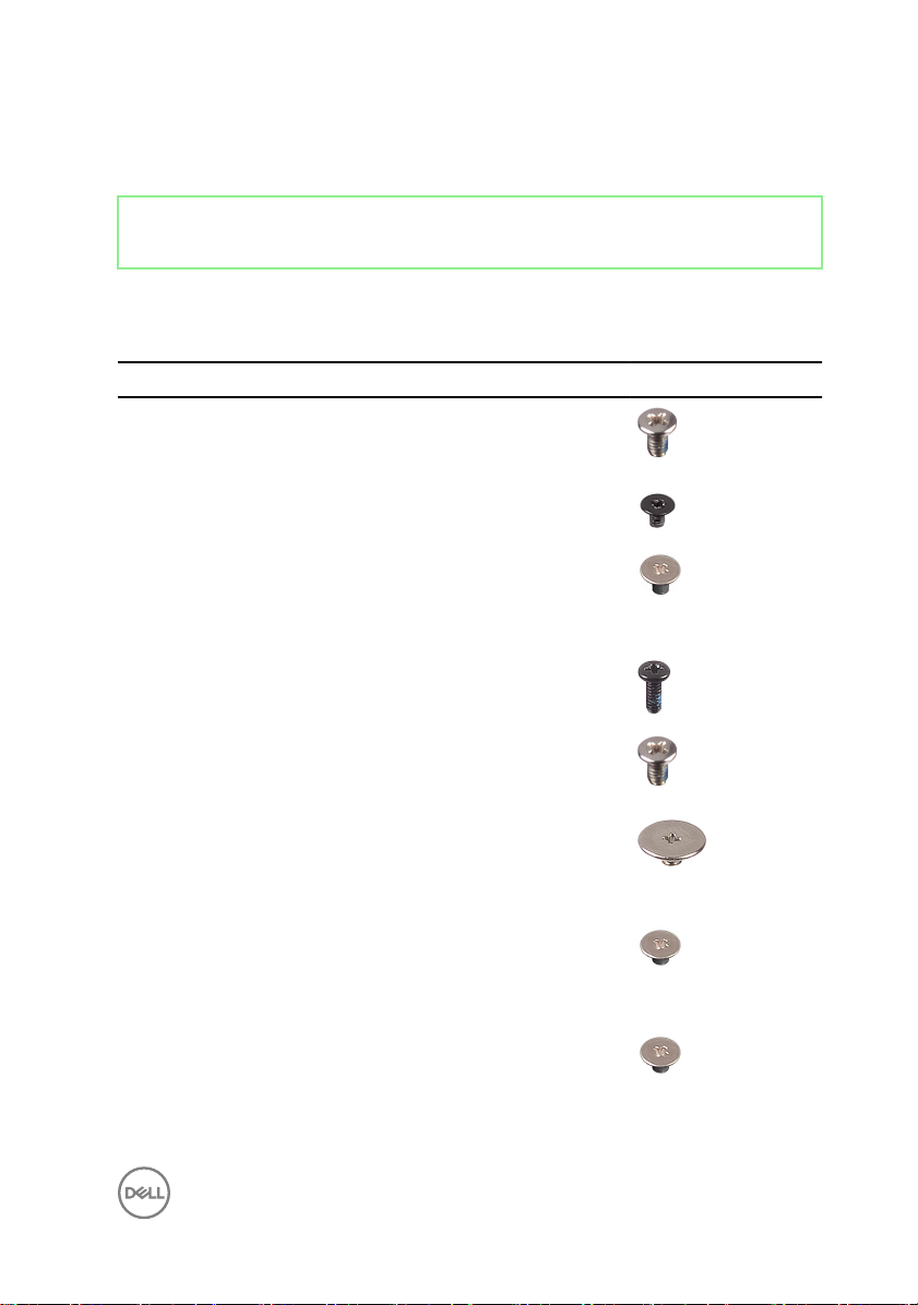
Table 1. Screw list
Component Secured to Screw type Quantity Screw image
Base cover Palm-rest and
keyboard
assembly
Battery System board M2x3 4
M2.5x4 7
Display panel Display back-
cover and
antenna
assembly
Fan System board M2x5 2
Hinges Palm-rest and
keyboard
assembly
Hinge brackets Display back-
cover and
antenna
assembly
Hinge brackets Display back-
cover and
antenna
assembly
I/O board Palm-rest and
keyboard
assembly
M2x2.5 4
M2.5x4 6
M2.5x2.5 6
M2x2 2
M2x2 2
13
Page 14
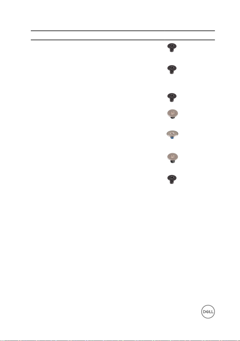
Component Secured to Screw type Quantity Screw image
Power-button Palm-rest and
keyboard
assembly
Power button
with ngerprint
reader
(optional)
Solid-state
drive
Palm-rest and
keyboard
assembly
System board M2x3 1
M2x3 2
M2x3 2
System board Palm-rest and
keyboard
assembly
Touchpad Palm-rest and
keyboard
assembly
Touchpad
(Support
brackets)
Wireless-card
bracket
Palm-rest and
keyboard
assembly
I/O board M2x5 1
M2x2 6
M2x2 4
M2x2.5 3
14
Page 15

Identifier GUID-06588814-2678-4667-9FF9-C009F4BCE185
Status Released
After working inside your computer
CAUTION: Leaving stray or loose screws inside your computer may severely
damage your computer.
1 Replace all screws and ensure that no stray screws remain inside your computer.
2 Connect any external devices, peripherals, or cables you removed before working
on your computer.
3 Replace any media cards, discs, or any other parts that you removed before
working on your computer.
4 Connect your computer and all attached devices to their electrical outlets.
5 Turn on your computer.
15
Page 16
Identifier GUID-98068FC2-1C1C-46DE-B3FA-DF9D488E9BA1
Status Released
Removing the base cover
WARNING: Before working inside your computer, read the safety
information that shipped with your computer and follow the steps in Before
working inside your computer. After working inside your computer, follow
the instructions in After working inside your computer. For more safety best
practices, see the Regulatory Compliance home page at www.dell.com/
regulatory_compliance.
Identifier GUID-13D13AE8-F0F8-481C-A244-7CB48C273392
Status Released
Procedure
1 Loosen the three captive screws on the base cover.
16
Page 17
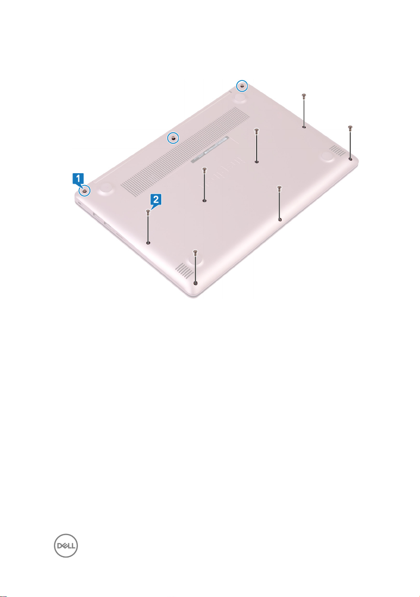
2 Remove the seven screws (M2.5x4) that secure the base cover to the palm-rest
and keyboard assembly.
3 Pry the base cover starting from the top-left corner of the computer base.
17
Page 18
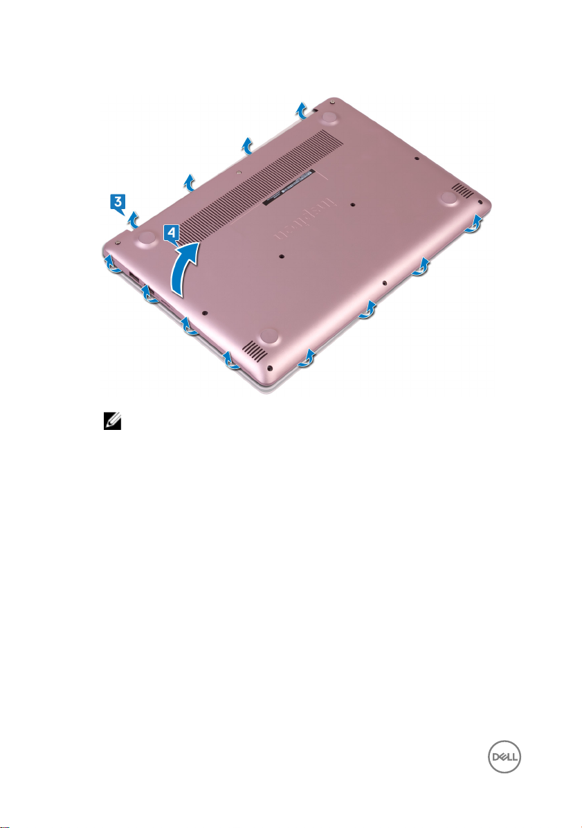
4 Lift the base cover o the palm-rest and keyboard assembly.
NOTE: The following steps are applicable only if you want to further
remove any other component from your computer.
18
Page 19
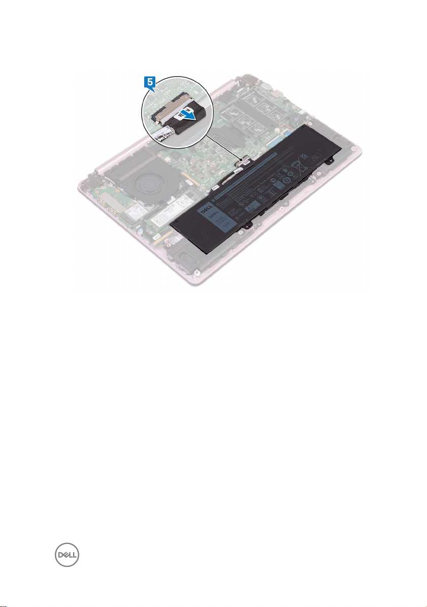
5 Disconnect the battery cable from the system board.
6 Press and hold the power button for 5 seconds to ground the computer and
drain the ea power.
19
Page 20
Identifier GUID-27446428-82D7-4881-9220-9EB090B046EA
Status Released
Replacing the base cover
WARNING: Before working inside your computer, read the safety
information that shipped with your computer and follow the steps in Before
working inside your computer. After working inside your computer, follow
the instructions in After working inside your computer. For more safety best
practices, see the Regulatory Compliance home page at www.dell.com/
regulatory_compliance.
Identifier GUID-B47BF7C4-C9B0-4896-A150-6B45442A712F
Status Released
Procedure
1 Connect the battery cable to the system board, if applicable.
CAUTION: To avoid accidental damage to the power-adapter port, do
not press the base cover against the power-adapter port when you
snap the base cover to the computer base.
2 Place the base cover on the palm-rest and keyboard assembly, and snap the
base cover into place starting from the power-adapter port.
3 Replace the seven screws (M2.5x4) that secure the base cover to the palm-rest
and keyboard assembly.
4 Tighten the three captive screws that secure the base cover to the palm-rest
and keyboard assembly.
20
Page 21

Identifier GUID-D9015C06-6CEE-42EA-9215-9D0FD7B827D5
Status Released
Removing the battery
WARNING: Before working inside your computer, read the safety
information that shipped with your computer and follow the steps in Before
working inside your computer. After working inside your computer, follow
the instructions in After working inside your computer. For more safety best
practices, see the Regulatory Compliance home page at www.dell.com/
regulatory_compliance.
Identifier GUID-155D1CCB-2139-4AF4-B1ED-97DF2BF00AA1
Status Released
Prerequisites
Remove the base cover.
21
Page 22
Identifier GUID-54359F58-556A-4BE8-A39B-A7E43DEDEBC5
Status Released
Procedure
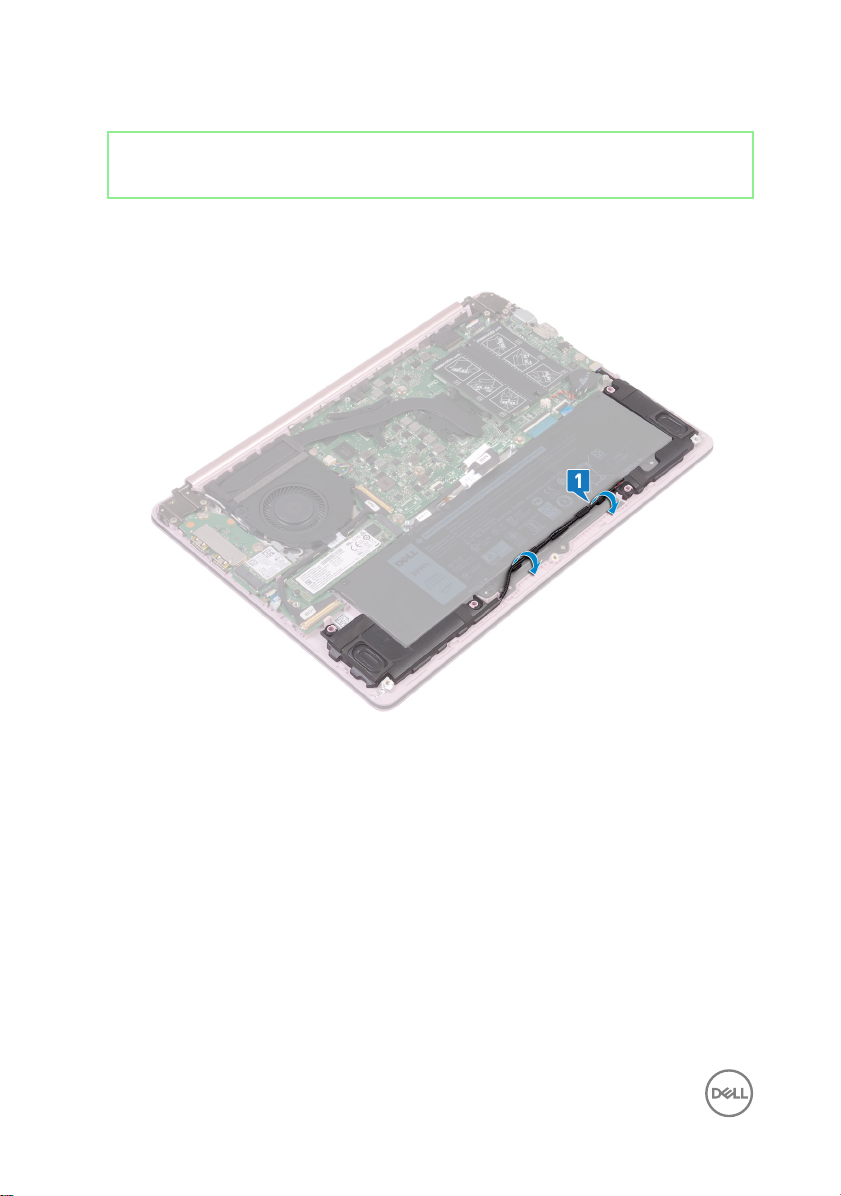
1 Remove the speaker cable from the cable routing on the battery.
2 Remove the four screws (M2x3) that secure the battery to the palm-rest and
keyboard assembly.
22
Page 23

3 Lift the battery o the palm-rest and keyboard assembly.
23
Page 24
Identifier GUID-E15EE482-44FD-4E71-91FC-899D4B61532E
Status Released
Replacing the battery
WARNING: Before working inside your computer, read the safety
information that shipped with your computer and follow the steps in Before
working inside your computer. After working inside your computer, follow
the instructions in After working inside your computer. For more safety best
practices, see the Regulatory Compliance home page at www.dell.com/
regulatory_compliance.
Identifier GUID-23E9F678-D1A9-43CA-9935-5FA5EABBB604
Status Released
Procedure
1 Align the screw holes on the battery with the screw holes on the palm-rest and
keyboard assembly.
2 Replace the four screws (M2x3) that secure the battery to the palm-rest and
keyboard assembly.
3 Replace the speaker cable along the cable routing on the battery.
Identifier GUID-174AF13A-4525-4DF6-A83C-B8131643436A
Status Released
Post-requisites
Replace the base cover.
24
Page 25

Identifier GUID-4290FDC0-A098-4D76-91B1-4DB14D54CD01
Status Released
Removing the memory module
WARNING: Before working inside your computer, read the safety
information that shipped with your computer and follow the steps in Before
working inside your computer. After working inside your computer, follow
the instructions in After working inside your computer. For more safety best
practices, see the Regulatory Compliance home page at www.dell.com/
regulatory_compliance.
Identifier GUID-155D1CCB-2139-4AF4-B1ED-97DF2BF00AA1
Status Released
Prerequisites
Remove the base cover.
25
Page 26
Identifier GUID-169E16C5-7890-4384-8FD6-5E21308E6D6F
Status Released
Procedure
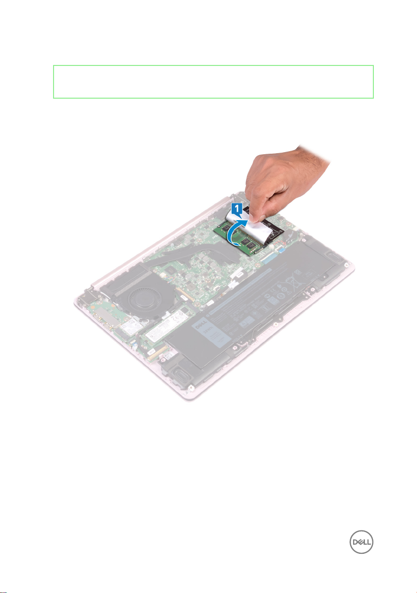
1 Locate the memory module and lift the Mylar to access the memory module.
2 Use your ngertips to carefully spread apart the securing-clips on each end of
the memory-module slot until the memory module pops up.
26
Page 27
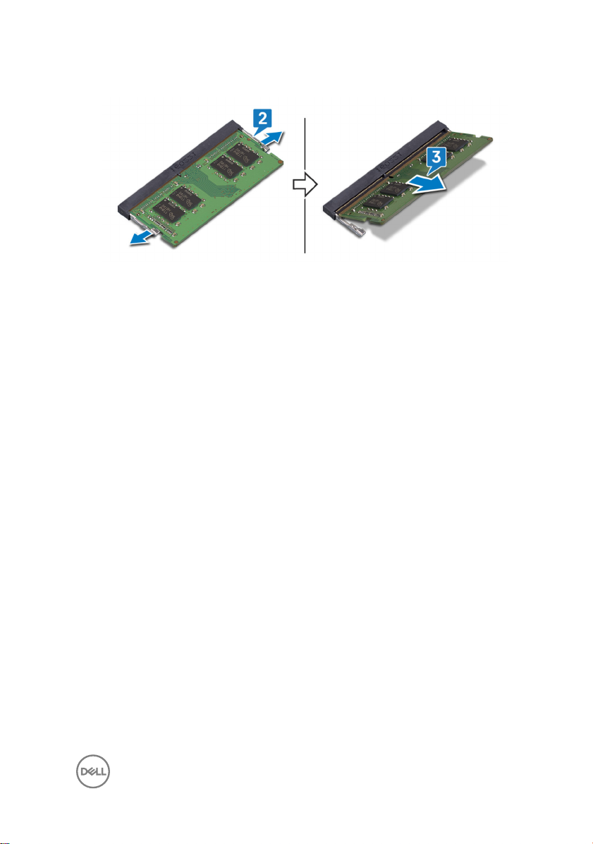
3 Remove the memory module from the memory-module slot.
27
Page 28
Identifier GUID-74047A37-7618-4FC3-8768-7B6A31495EB9
Status Released
Replacing the memory module
WARNING: Before working inside your computer, read the safety
information that shipped with your computer and follow the steps in Before
working inside your computer. After working inside your computer, follow
the instructions in After working inside your computer. For more safety best
practices, see the Regulatory Compliance home page at www.dell.com/
regulatory_compliance.
Identifier GUID-2163C33C-D12A-4DD2-A083-089BAFD66F28
Status Released
Procedure
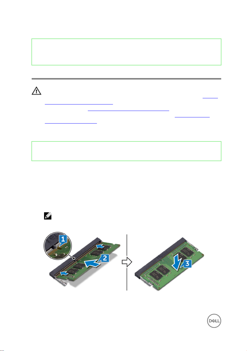
1 Lift the Mylar to access the memory-module slot.
2 Align the notch on the memory module with the tab on the memory-module slot.
3 Slide the memory module rmly into the slot at an angle.
4 Press the memory module down until it clicks into place.
NOTE: If you do not hear the click, remove the memory module and
reinstall it.
28
Page 29

Identifier GUID-174AF13A-4525-4DF6-A83C-B8131643436A
Status Released
Post-requisites
Replace the base cover.
29
Page 30

Identifier GUID-4AF7A7F4-79DC-43F4-A4DF-63362F890FB6
Status Released
Removing the wireless card
WARNING: Before working inside your computer, read the safety
information that shipped with your computer and follow the steps in Before
working inside your computer. After working inside your computer, follow
the instructions in After working inside your computer. For more safety best
practices, see the Regulatory Compliance home page at www.dell.com/
regulatory_compliance.
Identifier GUID-155D1CCB-2139-4AF4-B1ED-97DF2BF00AA1
Status Released
Prerequisites
Remove the base cover.
30
Page 31

Identifier GUID-8B8504EE-5A33-416B-9052-2147D33B6FF0
Status Released
Procedure
1 Locate the wireless card on your computer.
2 Remove the screw (M2x5) that secures the wireless-card bracket to the I/O
board.
3 Remove the wireless-card bracket from the wireless card.
4 Using a plastic scribe, disconnect the antenna cables from the wireless card.
31
Page 32

5 Angle and pull the wireless card to remove it from the wireless-card slot.
32
Page 33

Identifier GUID-94E88AEC-6F12-4B0E-AA6A-B28D8E200225
Status Released
Replacing the wireless card
WARNING: Before working inside your computer, read the safety
information that shipped with your computer and follow the steps in Before
working inside your computer. After working inside your computer, follow
the instructions in After working inside your computer. For more safety best
practices, see the Regulatory Compliance home page at www.dell.com/
regulatory_compliance.
Identifier GUID-94792422-279C-4098-B635-D4C4E04CF63D
Status Released
Procedure
CAUTION: To avoid damage to the wireless card, do not place any cables
under it.
1 Connect the antenna cables to the wireless card.
The following table provides the antenna-cable color scheme for the wireless
card supported by your computer.
Table 2. Antenna-cable color scheme
Connectors on the wireless card Antenna-cable color
Main (white triangle) White
Auxiliary (black triangle) Black
2 Align the notch on the wireless card with the tab on the wireless-card slot and
insert the wireless card at an angle into the wireless-card slot.
3 Place the wireless card bracket on the wireless card.
33
Page 34

4 Replace the screw (M2x5) that secures the wireless-card bracket to the wireless
card and the I/O board.
Identifier GUID-174AF13A-4525-4DF6-A83C-B8131643436A
Status Released
Post-requisites
Replace the base cover.
34
Page 35

Identifier GUID-30EEBC49-DE3E-4C3F-8226-86CE5F32F388
Status Released
Removing the coin-cell battery
WARNING: Before working inside your computer, read the safety
information that shipped with your computer and follow the steps in Before
working inside your computer. After working inside your computer, follow
the instructions in After working inside your computer. For more safety best
practices, see the Regulatory Compliance home page at www.dell.com/
regulatory_compliance.
CAUTION: Removing the coin-cell battery resets the BIOS setup program’s
settings to default. It is recommended that you note the BIOS setup
program’s settings before removing the coin-cell battery.
Identifier GUID-155D1CCB-2139-4AF4-B1ED-97DF2BF00AA1
Status Released
Prerequisites
Remove the base cover.
Identifier GUID-771C6BF5-50DF-46B9-9166-41EC35502AFC
Status Released
Procedure
CAUTION: Removing the coin-cell battery resets the BIOS setup program’s
settings to default. Before removing the coin-cell battery, it is recommended
to note the BIOS setup program’s settings.
1 Disconnect the coin-cell battery cable from the system board.
35
Page 36

2 Lift the coin-cell battery o from the system board.
36
Page 37

Identifier GUID-5E22F4A0-F01F-4522-8155-BE22A8CA6E5F
Status Released
Replacing the coin-cell battery
WARNING: Before working inside your computer, read the safety
information that shipped with your computer and follow the steps in Before
working inside your computer. After working inside your computer, follow
the instructions in After working inside your computer. For more safety best
practices, see the Regulatory Compliance home page at www.dell.com/
regulatory_compliance.
Identifier GUID-0058AB63-DE59-4398-B496-54EA8357DF69
Status Released
Procedure
1 Adhere the coin-cell battery on the system board.
2 Connect the coin-cell battery cable to the system board.
Identifier GUID-174AF13A-4525-4DF6-A83C-B8131643436A
Status Released
Post-requisites
Replace the base cover.
37
Page 38

Identifier GUID-FAA962E5-AD4D-4E85-BCA3-D99993D9AFD2
Status Released
Removing the fan
WARNING: Before working inside your computer, read the safety
information that shipped with your computer and follow the steps in Before
working inside your computer. After working inside your computer, follow
the instructions in After working inside your computer. For more safety best
practices, see the Regulatory Compliance home page at www.dell.com/
regulatory_compliance.
Identifier GUID-155D1CCB-2139-4AF4-B1ED-97DF2BF00AA1
Status Released
Prerequisites
Remove the base cover.
Identifier GUID-C7A536D9-510F-48B0-BE6C-CBA11AEBB3B6
Status Released
Procedure
1 Disconnect the fan cable from the system board.
2 Remove the two screws (M2x5) that secure the fan to the keyboard bracket.
38
Page 39

3 Lift the fan o the keyboard bracket.
39
Page 40

Identifier GUID-2596AFC0-F1E8-4A0E-A603-7D2CFE582ECE
Status Released
Replacing the fan
WARNING: Before working inside your computer, read the safety
information that shipped with your computer and follow the steps in Before
working inside your computer. After working inside your computer, follow
the instructions in After working inside your computer. For more safety best
practices, see the Regulatory Compliance home page at www.dell.com/
regulatory_compliance.
Identifier GUID-48D41CD6-79CC-4D5F-8DA1-1FB6A63A6D69
Status Released
Procedure
1 Align the screw holes on the fan with the screw holes on the system board.
2 Replace the two screws (M2x5) securing the fan to the system board.
3 Connect the fan cable to the system board.
Identifier GUID-174AF13A-4525-4DF6-A83C-B8131643436A
Status Released
Post-requisites
Replace the base cover.
40
Page 41

Identifier GUID-1C25F362-25CF-40CD-8A9B-2B98FB94F5FC
Status Released
Removing the solid-state drive
WARNING: Before working inside your computer, read the safety
information that shipped with your computer and follow the steps in Before
working inside your computer. After working inside your computer, follow
the instructions in After working inside your computer. For more safety best
practices, see the Regulatory Compliance home page at www.dell.com/
regulatory_compliance.
CAUTION: Solid-state drives are fragile. Exercise care when handling the
solid-state drive.
CAUTION: To avoid data loss, do not remove the solid-state drive while the
computer is in sleep or on state.
Identifier GUID-155D1CCB-2139-4AF4-B1ED-97DF2BF00AA1
Status Released
Prerequisites
Remove the base cover.
41
Page 42

Identifier GUID-69C33873-2D99-4505-99F2-6FEF20AB5A42
Status Released
Procedure
1 Locate the solid-state drive on the system board.
2 Remove the screw (M2x3) that secures the solid-state drive to the I/O board.
3 Lift and slide the solid-state drive to remove it from the solid-state drive slot on
the system board.
42
Page 43

Identifier GUID-792E5316-8EFA-4894-AE68-995416D3FD47
Status Released
Replacing the solid-state drive
WARNING: Before working inside your computer, read the safety
information that shipped with your computer and follow the steps in Before
working inside your computer. After working inside your computer, follow
the instructions in After working inside your computer. For more safety best
practices, see the Regulatory Compliance home page at www.dell.com/
regulatory_compliance.
CAUTION: Solid-state drives are fragile. Exercise care when handling the
solid-state drive.
Identifier GUID-F3ABFE45-5D15-43BC-A486-F0763178145E
Status Released
Procedure
1 Align the notch on the solid-state drive with the tab on the solid-state drive slot.
2 Slide the solid-state drive into the solid-state drive slot.
3 Replace the screw (M2x3) that secures the solid-state drive to the palm-rest
and keyboard assembly.
43
Page 44

Identifier GUID-174AF13A-4525-4DF6-A83C-B8131643436A
Status Released
Post-requisites
Replace the base cover.
44
Page 45

Identifier GUID-8D2AE471-594B-46FC-808B-9037BC410EC5
Status Released
Removing the touchpad
WARNING: Before working inside your computer, read the safety
information that shipped with your computer and follow the steps in Before
working inside your computer. After working inside your computer, follow
the instructions in After working inside your computer. For more safety best
practices, see the Regulatory Compliance home page at www.dell.com/
regulatory_compliance.
Identifier GUID-D4851626-2CCC-4647-B63A-149082551E1F
Status Released
Prerequisites
1 Remove the base cover.
2 Remove the battery.
Identifier GUID-490FD788-6CD1-40E3-8DFC-55279AE93E2F
Status Released
Procedure
1 Peel o the adhesive tape that secures the touchpad to the system board.
2 Open the latch and disconnect the touchpad cable from the system board.
3 Remove the four screws (M2x2) securing the touchpad to the palm-rest and
keyboard assembly.
45
Page 46

4 Angle and lift the touchpad from the slot on the palm-rest and keyboard
assembly.
46
Page 47

Identifier GUID-B55423C5-03BB-46A2-9B5F-B8F3B4C854AB
Status Released
Replacing the touchpad
WARNING: Before working inside your computer, read the safety
information that shipped with your computer and follow the steps in Before
working inside your computer. After working inside your computer, follow
the instructions in After working inside your computer. For more safety best
practices, see the Regulatory Compliance home page at www.dell.com/
regulatory_compliance.
Identifier GUID-BA365D1F-EA09-4C8C-821A-08EEE807DF19
Status Released
Procedure
1 Angle and slide the touchpad into the slots on the palm-rest and keyboard
assembly.
2 Replace the four screws (M2x2) that secure the touchpad to the palm-rest and
keyboard assembly.
3 Reconnect the touchpad cable to the system board and close the latch to secure
it.
4 Adhere the adhesive tape that secures the touchpad to the system board.
Identifier GUID-957FD87B-A0FD-42EE-ABEB-DA6D9BD2F27A
Status Released
Post-requisites
1 Replace the battery.
2 Replace the base cover.
47
Page 48

Identifier GUID-BF7F1ECA-BC62-4949-B1BE-EC64E351719E
Status Released
Removing the speakers
WARNING: Before working inside your computer, read the safety
information that shipped with your computer and follow the steps in Before
working inside your computer. After working inside your computer, follow
the instructions in After working inside your computer. For more safety best
practices, see the Regulatory Compliance home page at www.dell.com/
regulatory_compliance.
Identifier GUID-155D1CCB-2139-4AF4-B1ED-97DF2BF00AA1
Status Released
Prerequisites
Remove the base cover.
Identifier GUID-62AC26E6-E36D-4436-9E89-2B010D0898C5
Status Released
Procedure
1 Disconnect the speaker cable from the system board.
2 Lift the left speaker o the palm-rest and keyboard assembly.
3 Remove the speaker cable from the routing guides on the battery.
48
Page 49

4 Lift the right speaker o the palm-rest and keyboard assembly.
49
Page 50

Identifier GUID-40DC76F7-B3EC-450A-848E-632D68C352E2
Status Released
Replacing the speakers
WARNING: Before working inside your computer, read the safety
information that shipped with your computer and follow the steps in Before
working inside your computer. After working inside your computer, follow
the instructions in After working inside your computer. For more safety best
practices, see the Regulatory Compliance home page at www.dell.com/
regulatory_compliance.
Identifier GUID-4EB0E554-61A4-440C-A24B-AD74243EFF1C
Status Released
Procedure
1 Using the alignment posts, align and place the right speaker on the palm-rest and
keyboard assembly.
NOTE: Ensure the rubber seals t inside the grip of the alignment
posts.
2 Route the speaker cable through the routing guides on the battery.
3 Using the alignment posts, align and place the left speaker on the palm-rest and
keyboard assembly.
NOTE: Ensure the rubber seals t inside the grip of the alignment
posts.
4 Connect the speaker cable to the system board.
Identifier GUID-174AF13A-4525-4DF6-A83C-B8131643436A
Status Released
Post-requisites
Replace the base cover.
50
Page 51

Identifier GUID-3AE08A92-614C-4411-90FB-8693F1DE2634
Status Released
Removing the heat sink
WARNING: Before working inside your computer, read the safety
information that shipped with your computer and follow the steps in Before
working inside your computer. After working inside your computer, follow
the instructions in After working inside your computer. For more safety best
practices, see the Regulatory Compliance home page at www.dell.com/
regulatory_compliance.
WARNING: The heat sink may become hot during normal operation. Allow
sucient time for the heat sink to cool before you touch it.
CAUTION: For maximum cooling of the processor, do not touch the heat
transfer areas on the heat sink. The oils in your skin can reduce the heat
transfer capability of the thermal grease.
Identifier GUID-155D1CCB-2139-4AF4-B1ED-97DF2BF00AA1
Status Released
Prerequisites
Remove the base cover.
Identifier GUID-4910BE3D-64BF-4422-8661-AF975ACF6535
Status Released
Procedure
1 In reverse-sequential order (indicated on the heat-sink), loosen the captive
screws that secure the heat sink to the system board.
51
Page 52

2 Lift the heat sink o the system board.
NOTE: Depending on the conguration ordered, the type of heat sink
may be dierent from the illustration.
52
Page 53

Identifier GUID-69332260-F504-4C70-A535-1E11124CC185
Status Released
Replacing the heat sink
WARNING: Before working inside your computer, read the safety
information that shipped with your computer and follow the steps in Before
working inside your computer. After working inside your computer, follow
the instructions in After working inside your computer. For more safety best
practices, see the Regulatory Compliance home page at www.dell.com/
regulatory_compliance.
CAUTION: Incorrect alignment of the heat sink can damage the system
board and processor.
NOTE: The original thermal grease can be reused if the original system
board and heat sink are reinstalled together. If either the system board or
the heat sink is replaced, use the thermal pad provided in the kit to ensure
that thermal conductivity is achieved.
Identifier GUID-089BEFCC-CA73-4DC1-B3F3-1BD12B22CABB
Status Released
Procedure
1 Align the screw holes on the heat sink with the screw holes on the system board.
2 In sequential order (indicated on the heat sink), tighten the captive screws that
secure the heat sink to the system board.
Identifier GUID-174AF13A-4525-4DF6-A83C-B8131643436A
Status Released
Post-requisites
Replace the base cover.
53
Page 54

Identifier GUID-35D5032D-9652-403C-9A8A-F98FFABA8776
Status Released
Removing the power-adapter port
WARNING: Before working inside your computer, read the safety
information that shipped with your computer and follow the steps in
working inside your computer. After working inside your computer, follow
the instructions in After working inside your computer. For more safety best
practices, see the Regulatory Compliance home page at www.dell.com/
regulatory_compliance.
Identifier GUID-D4851626-2CCC-4647-B63A-149082551E1F
Status Released
Prerequisites
1 Remove the base cover.
2 Remove the battery.
Before
54
Page 55

Identifier GUID-19E9D97E-FE0F-4634-AAE6-DA30E8509DD9
Status Released
Procedure
1 Remove the two screws (M2.5x4) that secure the right hinge to the system
board and palm-rest and keyboard assembly.
55
Page 56

2 Lift the palm-rest and keyboard assembly at an angle to lift up the right hinge.
3 Disconnect the power-adapter port cable from the system board.
56
Page 57

4 Lift the power-adapter port, along with its cable, o the palm-rest and keyboard
assembly.
57
Page 58

Identifier GUID-A99140DB-7AF3-4218-B305-532FF94DF51D
Status Released
Replacing the power-adapter port
WARNING: Before working inside your computer, read the safety
information that shipped with your computer and follow the steps in
working inside your computer. After working inside your computer, follow
the instructions in After working inside your computer. For more safety best
practices, see the Regulatory Compliance home page at www.dell.com/
regulatory_compliance.
Identifier GUID-C29D8C26-1B0B-48A7-8AE1-F7CAB7EBB48F
Status Released
Procedure
1 Align the screw hole on the power-adapter port with the screw hole on the
palm-rest and keyboard assembly.
2 Connect the power-adapter port cable to the system board.
3 Close the right hinge and replace the two screws (M2.5x4) that secure the right
hinge to the system board and palm-rest and keyboard assembly.
Before
Identifier GUID-957FD87B-A0FD-42EE-ABEB-DA6D9BD2F27A
Status Released
Post-requisites
1 Replace the battery.
2 Replace the base cover.
58
Page 59

Identifier GUID-AB1F153B-621B-42FC-89BE-0E1105FF1786
Status Released
Removing the display assembly
WARNING: Before working inside your computer, read the safety
information that shipped with your computer and follow the steps in Before
working inside your computer. After working inside your computer, follow
the instructions in After working inside your computer. For more safety best
practices, see the Regulatory Compliance home page at www.dell.com/
regulatory_compliance.
Identifier GUID-B4299300-D1DA-4BD6-A6CF-AAEC73498A2D
Status Released
Prerequisites
1 Remove the base cover.
2 Remove the wireless card.
Identifier GUID-A215D1F0-2496-4D5D-9060-D3A5347D2B1F
Status Released
Procedure
1 Remove the four screws (M2.5x4) that secure the left and right hinges to the
system board and I/O board.
2 Note the routing of the antenna cables and remove the cables from the routing
guides on the fan.
59
Page 60

3 Disconnect the display cable from the system board.
60
Page 61

4 Lift the palm-rest and keyboard assembly at an angle.
61
Page 62

5 Slide and remove the palm-rest and keyboard assembly o the display assembly.
62
Page 63

6 After performing all the above steps, you are left with display assembly.
63
Page 64

Identifier GUID-2DF70EB1-9D26-4051-8B7C-FB14A89925D8
Status Released
Replacing the display assembly
WARNING: Before working inside your computer, read the safety
information that shipped with your computer and follow the steps in Before
working inside your computer. After working inside your computer, follow
the instructions in After working inside your computer. For more safety best
practices, see the Regulatory Compliance home page at www.dell.com/
regulatory_compliance.
Identifier GUID-D4C84B92-8049-4863-B02B-F1EB227D8C77
Status Released
Procedure
NOTE: Ensure that the hinges are opened to the maximum before replacing
the display assembly on the palm-rest and keyboard assembly.
1 Place the palm-rest and keyboard assembly under the hinges on the display
assembly.
2 Press the hinges down on the system board and I/O board.
3 Replace the four screws (M2.5x4) that secure the left and right hinges to the
system board and I/O board, ensuring they are aligned with the screw holes on
the alignment posts.
4 Connect the display cable to the system board.
5 Route the antenna cables through the routing guides on the fan.
Identifier GUID-CFA00B8E-6DC6-420A-8C89-EB3D66C287DD
Status Released
Post-requisites
1 Replace the wireless card.
64
Page 65

2 Replace the base cover.
65
Page 66

Identifier GUID-DC61C8F1-86D0-49DE-B8D8-229750E714D6
Status Released
Removing the I/O board
WARNING: Before working inside your computer, read the safety
information that shipped with your computer and follow the steps in Before
working inside your computer. After working inside your computer, follow
the instructions in After working inside your computer. For more safety best
practices, see the Regulatory Compliance home page at www.dell.com/
regulatory_compliance.
Identifier GUID-B270E7D3-1484-4A50-AA7C-FC2F7FA304C4
Status Released
Prerequisites
1 Remove the base cover.
2 Remove the solid-state drive.
3 Follow the procedure from step 1 to step 4 in Removing the wireless card.
66
Page 67

Identifier GUID-28E4D8EA-0C20-44F1-A579-48D01F711E62
Status Released
Procedure
1 Remove the two screws (M2.5x4) that secure the left hinge to the palm-rest
and keyboard assembly.
67
Page 68

2 Lift the palm-rest and keyboard assembly at an angle to lift up the left hinge.
3 Open the latch that secures the I/O-board cable, then disconnect the cable from
the I/O board.
4 Open the latch securing the ngerprint reader cable, then disconnect the cable
from the I/O board–Optional for computers shipped with ngerprint readers.
68
Page 69

5 Remove the two screws (M2x2) that secure the I/O board to the palm-rest and
keyboard assembly.
69
Page 70

Identifier GUID-98F27B1C-9F09-48EC-83D7-FC85C825E6A4
Status Released
Replacing the I/O board
WARNING: Before working inside your computer, read the safety
information that shipped with your computer and follow the steps in Before
working inside your computer. After working inside your computer, follow
the instructions in After working inside your computer. For more safety best
practices, see the Regulatory Compliance home page at www.dell.com/
regulatory_compliance.
Identifier GUID-538CD654-373E-4894-B946-C8CB3D76E4F8
Status Released
Procedure
NOTE: Ensure that the left hinge is opened to the maximum before replacing
the I/O board on palm-rest and keyboard assembly.
1 Using the alignment posts, place the I/O board on the palm-rest and keyboard
assembly.
2 Replace two screws (M2x2) that secure the I/O board to the palm-rest and
keyboard assembly.
3 Open the latch for securing the ngerprint reader cable to the I/O board, then
connect the cable to the I/O board–Optional for computers shipped with
ngerprint readers.
4 Open the latch for securing the I/O-board cable to the I/O board, then connect
the cable to the I/O board.
5 Close the left hinge down on to the palm-rest and keyboard assembly.
6 Replace the two screws (M2.5x4) that secure the left hinge to the palm-rest
and keyboard assembly.
70
Page 71

Identifier GUID-8F30ADCB-BFB6-418C-A8C9-9CCB6A50F1B7
Status Released
Post-requisites
1 Replace the wireless card.
2 Replace the solid-state drive.
3 Replace the base cover
71
Page 72

Identifier GUID-4F06B024-5674-42E6-943B-3000A6480544
Status Released
Removing the power button
WARNING: Before working inside your computer, read the safety
information that shipped with your computer and follow the steps in Before
working inside your computer. After working inside your computer, follow
the instructions in After working inside your computer. For more safety best
practices, see the Regulatory Compliance home page at www.dell.com/
regulatory_compliance.
Identifier GUID-CF260A94-1E93-43CB-AC32-36CFA1C664A6
Status Released
Prerequisites
1 Remove the base cover.
2 Remove the solid-state drive.
3 Remove the wireless card.
4 Remove the I/O board.
Identifier GUID-E7CE132E-35D8-425E-B639-793D165CE950
Status Released
Procedure
1 Remove the two screws (M2x3) that secure the power button to the palm-rest
and keyboard assembly.
72
Page 73

2 Lift the power button o the palm-rest and keyboard assembly.
73
Page 74

Identifier GUID-1A16CC4B-9BCB-45D9-A00E-CB738682EE96
Status Released
Replacing the power button
WARNING: Before working inside your computer, read the safety
information that shipped with your computer and follow the steps in Before
working inside your computer. After working inside your computer, follow
the instructions in After working inside your computer. For more safety best
practices, see the Regulatory Compliance home page at www.dell.com/
regulatory_compliance.
Identifier GUID-D0B6D94A-8D03-4B77-B0BC-E049F7081A4A
Status Released
Procedure
1 Using the alignment posts, align and place the power button on the palm-rest
and keyboard assembly.
2 Replace the screws (M2x3) that secure the power button to the palm-rest and
keyboard assembly.
Identifier GUID-C59C26BE-9C43-4CB5-93EC-0115AF21808C
Status Released
Post-requisites
1 Replace the I/O board.
2 Replace the wireless card.
3 Replace the solid-state drive.
4 Replace the base cover
74
Page 75

Identifier GUID-43423BFB-7BAA-4C7E-BA7A-12118E225EBA
Status Released
Removing the power button with
ngerprint reader
WARNING: Before working inside your computer, read the safety
information that shipped with your computer and follow the steps in
working inside your computer. After working inside your computer, follow
the instructions in After working inside your computer. For more safety best
practices, see the Regulatory Compliance home page at www.dell.com/
regulatory_compliance.
NOTE: Applicable only for computers that are shipped with ngerprint
reader.
Identifier GUID-CF260A94-1E93-43CB-AC32-36CFA1C664A6
Status Released
Prerequisites
1 Remove the base cover.
2 Remove the solid-state drive.
3 Remove the wireless card.
4 Remove the I/O board.
Before
Identifier GUID-11BA495C-6BF1-48C4-AECE-8174D6EDDFEC
Status Released
Procedure
1 Remove the screw (M2x3) that secures the power button with ngerprint reader
to the palm-rest and keyboard assembly.
2 Using a plastic scribe, release the ngerprint-reader board from the guides on
the palm-rest and keyboard assembly.
75
Page 76

3 Lift the power button with ngerprint reader, along with its cable, o the palm-
rest and keyboard assembly.
76
Page 77

Identifier GUID-0C3EE813-46D4-4A46-9435-5A8AE8783F68
Status Released
Replacing the power button with
ngerprint reader
WARNING: Before working inside your computer, read the safety
information that shipped with your computer and follow the steps in
working inside your computer. After working inside your computer, follow
the instructions in After working inside your computer. For more safety best
practices, see the Regulatory Compliance home page at www.dell.com/
regulatory_compliance.
NOTE: Applicable only for computers that are shipped with ngerprint
reader.
Identifier GUID-2951C8A3-4616-4A59-9D42-B3BD05DD3072
Status Released
Procedure
1 Using the alignment posts, align and place the power button with ngerprint
reader on the palm-rest and keyboard assembly.
2 Replace the screw (M2x3) that secures the power button with ngerprint reader
to the palm-rest and keyboard assembly.
Before
Identifier GUID-C59C26BE-9C43-4CB5-93EC-0115AF21808C
Status Released
Post-requisites
1 Replace the I/O board.
2 Replace the wireless card.
3 Replace the solid-state drive.
4 Replace the base cover
77
Page 78

Identifier GUID-B54497E8-5AD5-4FF9-AD4A-F32FDBEDE1E8
Status Released
Removing the system board
WARNING: Before working inside your computer, read the safety
information that shipped with your computer and follow the steps in Before
working inside your computer. After working inside your computer, follow
the instructions in After working inside your computer. For more safety best
practices, see the Regulatory Compliance home page at www.dell.com/
regulatory_compliance.
NOTE: Your computer’s Service Tag is stored in the system board. You must
enter the Service Tag in the BIOS setup program after you replace the
system board.
NOTE: Replacing the system board removes any changes you have made to
the BIOS using the BIOS setup program. You must make the appropriate
changes again after you replace the system board.
NOTE: Before disconnecting the cables from the system board, note the
location of the connectors so that you can reconnect the cables correctly
after you replace the system board.
Identifier GUID-FDBA4CE9-A347-475F-BB17-9D1818356502
Status Released
Prerequisites
1 Remove the base cover.
2 Remove the battery.
3 Remove the solid-state drive.
4 Remove the fan.
5 Remove the heat sink.
6 Remove the memory module.
78
Page 79

Identifier GUID-E3E78115-81ED-44E3-ACC6-5020DB7C4437
Status Released
Procedure
1 Disconnect the display cable from the system board.
2 Disconnect the power-adapter port cable from the system board.
3 Remove the two screws (M2x5) that secure the USB Type C port bracket to the
system board.
4 Remove the USB Type C port bracket.
5 Disconnect the speaker cable from the system board.
6 Open the latch and disconnect the touchpad cable from the system board.
7 Open the latch and disconnect the keyboard cable from the system board.
8 Open the latch and disconnect the keyboard back-light cable from the system
board–Optional for computers shipped with backlit keyboards.
79
Page 80

9 Open the latch and disconnect the I/O board cable from the system board.
10 Remove the six screws (M2x2) that secure the system board to the palm-rest
and keyboard assembly.
80
Page 81

11 Lift the system board o the palm-rest and keyboard assembly.
81
Page 82

Identifier GUID-67274E98-E2F1-4B7B-A903-F38BA6B62028
Status Released
Replacing the system board
WARNING: Before working inside your computer, read the safety
information that shipped with your computer and follow the steps in Before
working inside your computer. After working inside your computer, follow
the instructions in After working inside your computer. For more safety best
practices, see the Regulatory Compliance home page at www.dell.com/
regulatory_compliance.
NOTE: Your computer’s Service Tag is stored in the system board. You must
enter the Service Tag in the BIOS setup program after you replace the
system board.
NOTE: Replacing the system board removes any changes you have made to
the BIOS using the BIOS setup program. You must make the appropriate
changes again after you replace the system board.
Identifier GUID-66FBE441-7580-4C3B-8D58-B3D1D92EE5BA
Status Released
Procedure
1 Align the screw holes on the system board with the screw holes on the palm-rest
and keyboard assembly.
2 Replace the six screws (M2x2) that secure the system board to the palm-rest
and keyboard assembly.
3 Slide the I/O-board cable into its respective connector on the system board and
close the latch.
4 Slide the keyboard back-light cable into its respective connector on the system
board and close the latch–Optional for computers shipped with backlit
keyboards.
5 Slide the keyboard cable into its respective connector on the system board and
close the latch.
82
Page 83

6 Slide the touchpad cable into its respective connector on the system board and
close the latch.
7 Connect the speaker cable from the system board.
8 Align the screw holes of the USB Type C bracket with the screw holes on the
system board and palm-rest and keyboard assembly.
9 Replace the two screws (M2x5) that secure the USB Type C port bracket to the
system board.
10 Connect the power-adapter port cable to the system board.
11 Connect the display cable to the system board.
Identifier GUID-5CBD1806-EF57-4769-9E26-75062C502E20
Status Released
Post-requisites
1 Replace the memory module.
2 Replace the heat sink.
3 Replace the fan.
4 Replace the solid-state drive.
5 Replace the battery.
6 Replace the base cover.
Identifier GUID-C264FC4F-B5CD-4F08-9183-CB9FC26A5E6A
Status Released
Entering the Service Tag in the BIOS setup program
1 Turn on or restart your computer.
2 Press F2 when the Dell logo is displayed to enter the BIOS setup program.
3 Navigate to the Main tab and enter the Service Tag in the Service Tag Input
eld.
NOTE: Service tag is the alphanumeric identier located at the back side of
your computer.
83
Page 84

Identifier GUID-631184FE-18D9-4002-8F9F-DDB8690B3A74
Status Released
Removing the palm rest and keyboard assembly
WARNING: Before working inside your computer, read the safety
information that shipped with your computer and follow the steps in
working inside your computer. After working inside your computer, follow
the instructions in After working inside your computer. For more safety best
practices, see the Regulatory Compliance home page at www.dell.com/
regulatory_compliance.
Identifier GUID-88238D1C-DF55-4EEB-A9F8-D09A762EADFC
Status Released
Prerequisites
1 Remove the base cover.
2 Remove the battery.
3 Remove the speakers.
4 Remove the solid-state drive.
5 Remove the wireless card.
6 Remove the I/O board.
7 Remove the power button or power button with ngerprint reader(if installed).
8 Remove the fan.
9 Remove the heat sink.
10 Remove the coin-cell battery.
11 Remove the display assembly.
12 Remove the system board.
13 Remove the touchpad.
Before
84
Page 85

Identifier GUID-0353C77F-F4FB-4BCA-B792-542BF785D623
Status Released
Procedure
After performing the above steps, we are left with the palm-rest and keyboard
assembly.
85
Page 86

Identifier GUID-A7F798E1-C24C-44A0-9D6E-60A24BC170F6
Status Released
Replacing the palm rest and keyboard assembly
WARNING: Before working inside your computer, read the safety
information that shipped with your computer and follow the steps in
working inside your computer. After working inside your computer, follow
the instructions in After working inside your computer. For more safety best
practices, see the Regulatory Compliance home page at www.dell.com/
regulatory_compliance.
Identifier GUID-80E891B4-8E62-4A04-B0A2-ABA989294A60
Status Released
Procedure
Place the palm-rest and keyboard assembly on a at surface.
Identifier GUID-2E68A426-1C5E-45E5-BE95-407A88D28DCF
Status Released
Before
Post-requisites
1 Replace the touchpad.
2 Replace the system board.
3 Replace the display assembly.
4 Replace the coin-cell battery.
5 Replace the heat sink.
6 Replace the fan.
7 Replace the power button or power button with ngerprint reader(if installed).
8 Replace the I/O board.
86
Page 87

9 Replace the wireless card.
10 Replace the solid-state drive.
11 Replace the battery.
12 Replace the speakers.
13 Replace the base cover.
87
Page 88

Identifier GUID-5C27B5F7-0EC4-42CD-AB68-CFC88E655D56
Status Released
Removing the display bezel
WARNING: Before working inside your computer, read the safety
information that shipped with your computer and follow the steps in Before
working inside your computer. After working inside your computer, follow
the instructions in After working inside your computer. For more safety best
practices, see the Regulatory Compliance home page at www.dell.com/
regulatory_compliance.
Identifier GUID-6D14CBC1-99CB-44AC-A38C-EF018E7A6A72
Status Released
Prerequisites
1 Remove the base cover.
2 Remove the wireless card.
3 Remove the display assembly.
Identifier GUID-4DCF6C4F-E45A-4149-AFB0-7977A70A8680
Status Released
Procedure
1 Using a plastic scribe, carefully pry the display bezel from the top-left,outer edge
of the display back-cover and antenna assembly.
88
Page 89

2 Remove the display bezel o the display back-cover and antenna assembly.
89
Page 90

Identifier GUID-619F529E-294B-4F0D-BB9D-9B71EB448811
Status Released
Replacing the display bezel
WARNING: Before working inside your computer, read the safety
information that shipped with your computer and follow the steps in Before
working inside your computer. After working inside your computer, follow
the instructions in After working inside your computer. For more safety best
practices, see the Regulatory Compliance home page at www.dell.com/
regulatory_compliance.
Identifier GUID-F23615E5-DCEF-4464-BFC5-2B203D6B9441
Status Released
Procedure
Align the display bezel with the display back-cover and antenna assembly, then gently
snap the display bezel into place.
Identifier GUID-D26E8501-D718-4922-B27C-D035281DFE3D
Status Released
Post-requisites
1 Replace the display assembly.
2 Replace the wireless card.
3 Replace the base cover.
90
Page 91

Identifier GUID-1FB16E7C-AF0C-4FA0-8736-EAD91D8969A8
Status Released
Removing the camera
WARNING: Before working inside your computer, read the safety
information that shipped with your computer and follow the steps in Before
working inside your computer. After working inside your computer, follow
the instructions in After working inside your computer. For more safety best
practices, see the Regulatory Compliance home page at www.dell.com/
regulatory_compliance.
Identifier GUID-CC46340A-BBC5-430D-A286-F736D7F61421
Status Released
Prerequisites
1 Remove the base cover.
2 Remove the wireless card.
3 Remove the display assembly.
4 Remove the display bezel.
5 Remove the display panel.
Identifier GUID-04EE7807-2678-4A7A-BF92-F248631082DA
Status Released
Procedure
1 Using a plastic scribe, gently pry the camera o the display back-cover and
antenna assembly.
2 Disconnect the camera cable from the camera module.
91
Page 92

3 Lift the camera module from the display back-cover and antenna assembly.
92
Page 93

Identifier GUID-690FF12D-2581-4326-8270-C4B813388FD3
Status Released
Replacing the camera
WARNING: Before working inside your computer, read the safety
information that shipped with your computer and follow the steps in Before
working inside your computer. After working inside your computer, follow
the instructions in After working inside your computer. For more safety best
practices, see the Regulatory Compliance home page at www.dell.com/
regulatory_compliance.
Identifier GUID-C06A2E8F-C2F2-4A3D-8190-589A92377471
Status Released
Procedure
1 Connect the camera cable to the camera module.
2 Using the alignment post adhere the camera module on the display back-cover
and antenna assembly.
Identifier GUID-7EEE38D1-7D07-4267-8495-D699814FA763
Status Released
Post-requisites
1 Replace the display panel.
2 Replace the display bezel.
3 Replace the display assembly.
4 Replace the wireless card.
5 Replace the base cover.
93
Page 94

Identifier GUID-7D2CEA1B-1FC0-4606-86EB-F51C5DFB6E52
Status Released
Removing the display panel
WARNING: Before working inside your computer, read the safety
information that shipped with your computer and follow the steps in Before
working inside your computer. After working inside your computer, follow
the instructions in After working inside your computer. For more safety best
practices, see the Regulatory Compliance home page at www.dell.com/
regulatory_compliance.
Identifier GUID-01302A0E-60AE-44C3-ACBE-927639F64D86
Status Released
Prerequisites
1 Remove the base cover.
2 Remove the wireless card.
3 Remove the display assembly.
4 Remove the display bezel.
Identifier GUID-CB3D62AF-8575-4094-AB31-F6BE6222940F
Status Released
Procedure
1 Remove the four screws (M2x2.5) that secure the display panel to the display
back-cover and antenna assembly.
94
Page 95

2 Lift the display panel and turn it over.
3 Peel the tape adhering the display cable to the back of the display panel.
4 Lift the latch and disconnect the display cable from the display-panel cable
connector.
95
Page 96

5 Lift the display panel away from the display back-cover and antenna assembly.
96
Page 97

Identifier GUID-6FD32244-34F4-4843-983D-B6C14903EFC9
Status Released
Replacing the display panel
WARNING: Before working inside your computer, read the safety
information that shipped with your computer and follow the steps in Before
working inside your computer. After working inside your computer, follow
the instructions in After working inside your computer. For more safety best
practices, see the Regulatory Compliance home page at www.dell.com/
regulatory_compliance.
Identifier GUID-A2D8EE11-0781-4425-B764-A6F7D5560882
Status Released
Procedure
1 Place the display panel on a at and clean surface.
2 Connect the display cable to the connector at the back of the display panel and
close the latch to secure the cable.
3 Adhere the tape that secures the display cable to the back of the display panel.
4 Align the screw holes on the display panel with the screw holes on the display
back-cover and antenna assembly.
5 Replace the four screws (M2 x2.5) that secure the display panel to the display
back-cover and antenna assembly.
Identifier GUID-49EE712E-57EE-4EB5-8927-0BAB3C595DE7
Status Released
Post-requisites
1 Replace the display bezel.
2 Replace the display assembly.
3 Replace the wireless card.
4 Replace the base cover.
97
Page 98

Identifier GUID-6C4E9746-B780-409D-B703-9A43273C227D
Status Released
Removing the display hinges
WARNING: Before working inside your computer, read the safety
information that shipped with your computer and follow the steps in Before
working inside your computer. After working inside your computer, follow
the instructions in After working inside your computer. For more safety best
practices, see the Regulatory Compliance home page at www.dell.com/
regulatory_compliance.
Identifier GUID-ADEDC61C-95BA-47CA-98CD-DF686728A0DA
Status Released
Prerequisites
1 Remove the base cover.
2 Remove the wireless card.
3 Remove the display assembly.
4 Remove the display bezel.
5 Remove the display panel.
Identifier GUID-9CE1A5DB-816A-49A4-9CFC-E8347F240D94
Status Released
Procedure
1 Remove the six screws (M2.5x2.5) that secure the hinges to the display back-
cover and antenna assembly.
2 Remove the two screws (M2x2) that secure the hinge brackets to the display
back-cover and antenna assembly.
3 Using a plastic scribe, pry the brackets away from the guides on the display
back-cover and antenna assembly.
98
Page 99

4 Lift the hinges and brackets o the display back-cover and antenna assembly.
99
Page 100

Identifier GUID-E3D5A4DB-BAB5-4F6F-B7B6-8BC4EF0CC57D
Status Released
Replacing the display hinges
WARNING: Before working inside your computer, read the safety
information that shipped with your computer and follow the steps in Before
working inside your computer. After working inside your computer, follow
the instructions in After working inside your computer. For more safety best
practices, see the Regulatory Compliance home page at www.dell.com/
regulatory_compliance.
Identifier GUID-48ED5BAA-A313-45EB-8062-1674CE879F78
Status Released
Procedure
1 Align the screw holes on the hinges and brackets with the screw holes on the
display back-cover and antenna assembly.
2 Replace the two screws (M2x2) that secure the hinges to the display back-
cover and antenna assembly.
3 Replace the six screws (M2.5x2.5) that secure the hinges to the display back-
cover and antenna assembly .
Identifier GUID-D7DB8FF8-D4A4-4CE7-9604-12364347D480
Status Released
Post-requisites
1 Replace the display panel.
2 Replace the display bezel.
3 Replace the display assembly.
4 Replace the wireless card.
5 Replace the base cover.
100
 Loading...