

Dell Inspiron 15R, Inspiron 15R 5520, I15R-2105SLV Owner's Manual

лчиттничюнльтцию.
глтчн.Бзвыдны
www.sotmarket.ru
дбняинфмциятв,
тзывы,бзыиы
Инструкция для
Dell Inspiron 7520
Перейти в карточку товара
8 800 775 98 98

Dell Inspiron 15R
Owner’s Manual
Computer model: Inspiron 5520/7520
Regulatory model: P25F
Regulatory type: P25F001

Notes, Cautions, and Warnings
NOTE: A NOTE indicates important information that helps you make
better use of your computer.
CAUTION: A CAUTION indicates potential damage to hardware or loss
of data if instructions are not followed.
WARNING: A WARNING indicates a potential for property damage,
personal injury, or death.
____________________
Information in this document is subject to change without notice.
© 2012 Dell Inc. All rights reserved.
Reproduction of these materials in any manner whatsoever without the written permission
of Dell Inc. is strictly forbidden.
Trademarks used in this text: Dell™, the DELL logo, and Inspiron™ are trademarks of Dell
Inc.; Microsoft
®
, Windows®, and the Windows start button logo
are either trademarks
or registered trademarks of Microsoft corporation in the United States and/or other
countries; Bluetooth
®
is a registered trademark owned by Bluetooth SIG, Inc. and is used
by Dell under license.
Other trademarks and trade names may be used in this document to refer to either the
entities claiming the marks and names or their products. Dell Inc. disclaims any proprietary
interest in trademarks and trade names other than its own.
2012 - 04 Rev. A00

Contents | 3
Contents
1Before You Begin . . . . . . . . . . . . . . . . . . . . . . . . 7
Turn Off Your Computer and Connected Devices . . . 7
Safety Instructions . . . . . . . . . . . . . . . . . . . . . . . . 7
Recommended Tools . . . . . . . . . . . . . . . . . . . . . . 8
2 After Working Inside Your Computer . . . . . . . . 9
3Switch. . . . . . . . . . . . . . . . . . . . . . . . . . . . . . . . 11
Removing the Switch . . . . . . . . . . . . . . . . . . . . . 11
Replacing the Switch . . . . . . . . . . . . . . . . . . . . . 12
4Battery. . . . . . . . . . . . . . . . . . . . . . . . . . . . . . . . 13
Removing the Battery . . . . . . . . . . . . . . . . . . . . . 13
Replacing the Battery . . . . . . . . . . . . . . . . . . . . . 13
5Keyboard. . . . . . . . . . . . . . . . . . . . . . . . . . . . . . 15
Removing the Keyboard . . . . . . . . . . . . . . . . . . . 15
Replacing the Keyboard . . . . . . . . . . . . . . . . . . . 16
6 Base Cover . . . . . . . . . . . . . . . . . . . . . . . . . . . . 17
Removing the Base Cover . . . . . . . . . . . . . . . . . . 17
Replacing the Base Cover . . . . . . . . . . . . . . . . . . 18
7 Memory Module(s) . . . . . . . . . . . . . . . . . . . . . . 19
Removing the Memory Module(s). . . . . . . . . . . . . 19
Replacing the Memory Module(s) . . . . . . . . . . . . . 20
8Hard Drive. . . . . . . . . . . . . . . . . . . . . . . . . . . . . 21
Removing the Hard Drive . . . . . . . . . . . . . . . . . . 21
Replacing the Hard Drive . . . . . . . . . . . . . . . . . . 23
9 Optical Drive. . . . . . . . . . . . . . . . . . . . . . . . . . . 25
Removing the Optical Drive. . . . . . . . . . . . . . . . . 25
Replacing the Optical Drive . . . . . . . . . . . . . . . . . 26

4 | Contents
10 Palm Rest . . . . . . . . . . . . . . . . . . . . . . . . . . . . . 27
Removing the Palm Rest . . . . . . . . . . . . . . . . . . . 27
Replacing the Palm Rest . . . . . . . . . . . . . . . . . . . 31
11 Power-Adapter Port. . . . . . . . . . . . . . . . . . . . . 33
Removing the Power-Adapter Port . . . . . . . . . . . . 33
Replacing the Power-Adapter Port . . . . . . . . . . . . 34
12 Display Assembly . . . . . . . . . . . . . . . . . . . . . . . 35
Removing the Display Assembly . . . . . . . . . . . . . . 35
Replacing the Display Assembly . . . . . . . . . . . . . . 37
Removing the Display Bezel . . . . . . . . . . . . . . . . 37
Replacing the Display Bezel. . . . . . . . . . . . . . . . . 38
Removing the Hinge Caps. . . . . . . . . . . . . . . . . . 39
Replacing the Hinge Caps . . . . . . . . . . . . . . . . . . 40
Removing the Display Panel . . . . . . . . . . . . . . . . 40
Replacing the Display Panel. . . . . . . . . . . . . . . . . 43
13 Camera Module . . . . . . . . . . . . . . . . . . . . . . . . 45
Removing the Camera Module. . . . . . . . . . . . . . . 45
Replacing the Camera Module . . . . . . . . . . . . . . . 48
14 System Board . . . . . . . . . . . . . . . . . . . . . . . . . . 49
Removing the System Board . . . . . . . . . . . . . . . . 49
Replacing the System Board . . . . . . . . . . . . . . . . 52
Entering the Service Tag in the BIOS . . . . . . . . . . . 53
15 Thermal-Cooling Assembly. . . . . . . . . . . . . . . 55
Removing the Thermal-Cooling Assembly . . . . . . . 55
Replacing the Thermal-Cooling Assembly . . . . . . . 57
16 Processor . . . . . . . . . . . . . . . . . . . . . . . . . . . . . 59
Removing the Processor . . . . . . . . . . . . . . . . . . . 59
Replacing the Processor . . . . . . . . . . . . . . . . . . . 61
17 Coin-Cell Battery . . . . . . . . . . . . . . . . . . . . . . . 63
Removing the Coin-Cell Battery. . . . . . . . . . . . . . 63
Replacing the Coin-Cell Battery . . . . . . . . . . . . . . 65

Contents | 5
18 Speakers . . . . . . . . . . . . . . . . . . . . . . . . . . . . . . 67
Removing the Speakers . . . . . . . . . . . . . . . . . . . 67
Replacing the Speakers. . . . . . . . . . . . . . . . . . . . 69
19 Media Card Reader. . . . . . . . . . . . . . . . . . . . . . 71
Removing the Media Card Reader . . . . . . . . . . . . 71
Replacing the Media Card Reader. . . . . . . . . . . . . 73
20 Daughter Board . . . . . . . . . . . . . . . . . . . . . . . . 75
Removing the Daughter Board. . . . . . . . . . . . . . . 75
Replacing the Daughter Board . . . . . . . . . . . . . . . 77
21 Mini-Card . . . . . . . . . . . . . . . . . . . . . . . . . . . . . 79
Removing the Mini-Card. . . . . . . . . . . . . . . . . . . 79
Replacing the Mini-Card . . . . . . . . . . . . . . . . . . . 80
22 Flashing the BIOS . . . . . . . . . . . . . . . . . . . . . . . 83

6 | Contents

Before You Begin | 7
1
Before You Begin
Turn Off Your Computer and Connected Devices
CAUTION: To avoid losing data, save and close all open files and exit all open
programs before you turn off your computer.
1 Save and close all open files and exit all open programs.
2 Click Start and click Shut down.
Microsoft Windows shuts down and then the computer turns off.
NOTE: If you are using a different operating system, see the documentation of
your operating system for shut-down instructions.
3 Disconnect your computer and all attached devices from their electrical outlets.
4 Disconnect all telephone cables, network cables, and attached devices from your
computer.
5 Press and hold the power button for about 5 seconds, after the computer is
unplugged, to ground the system board.
Safety Instructions
Use the following safety guidelines to protect your computer from potential damage and
ensure your personal safety.
WARNING: Before working inside your computer, read the safety information
that shipped with your computer. For additional safety best practices
information, see the Regulatory Compliance Homepage at dell.com/
regulatory_compliance.
WARNING: Disconnect all power sources before opening the computer cover or
panels. After you finish working inside the computer, replace all covers, panels,
and screws before connecting to the power source.
CAUTION: To avoid damaging the computer, ensure that the work surface is flat
and clean.
CAUTION: To avoid damaging the components and cards, handle them by their
edges and avoid touching pins and contacts.
CAUTION: Only a certified service technician is authorized to remove the
computer cover and access any of the components inside the computer. See the
safety instructions for complete information about safety precautions, working
inside your computer, and protecting against electrostatic discharge.
CAUTION: Before touching anything inside your computer, ground yourself by
touching an unpainted metal surface, such as the metal at the back of the
computer. While you work, periodically touch an unpainted metal surface to
dissipate static electricity, which could harm internal components.

8 | Before You Begin
CAUTION: When you disconnect a cable, pull on its connector or on its pull-tab,
not on the cable itself. Some cables have connectors with locking tabs or
thumb-screws that you must disengage before disconnecting the cable. When
disconnecting cables, keep them evenly aligned to avoid bending any connector
pins. When connecting cables, ensure that the connectors and ports are correctly
oriented and aligned.
CAUTION: To disconnect a network cable, first unplug the cable from your
computer and then unplug the cable from the network device.
Recommended Tools
The procedures in this document may require the following tools:
• Phillips screwdriver
• Plastic scribe
• Small flat-blade screwdriver

After Working Inside Your Computer | 9
2
After Working Inside Your Computer
After you complete replacement procedures, ensure the following:
• Replace all screws and ensure that no stray screws remain inside your computer
• Connect any external devices, cables, cards, and any other part(s) you removed
before working on your computer
• Connect your computer and all attached devices to their electrical outlets
CAUTION: Before turning on your computer, replace all screws and ensure that
no stray screws remain inside the computer. Failure to do so may damage your
computer.

10 | After Working Inside Your Computer
Switch | 11
3
Switch
WARNING: Before working inside your computer, read the safety information
that shipped with your computer and follow the steps in "Before You Begin" on
page 7. For additional safety best practices information, see the Regulatory
Compliance Homepage at dell.com/regulatory_compliance.
Removing the Switch
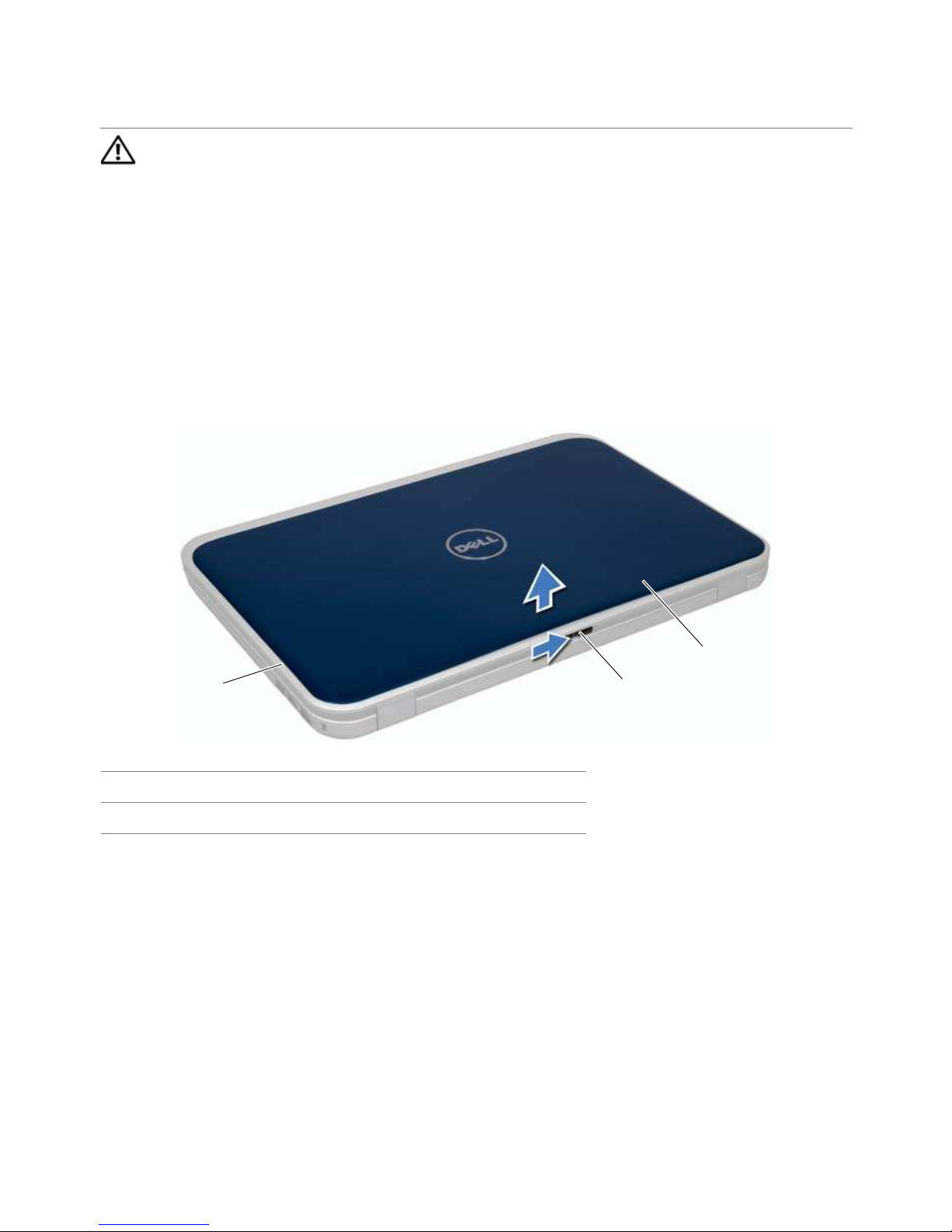
1 Slide the switch release latch to the side.
The switch pops up.
2 Lift the switch off the computer.
1 display cover 2 switch release latch
3switch
1
2
3
12 | Switch
Replacing the Switch
Procedure
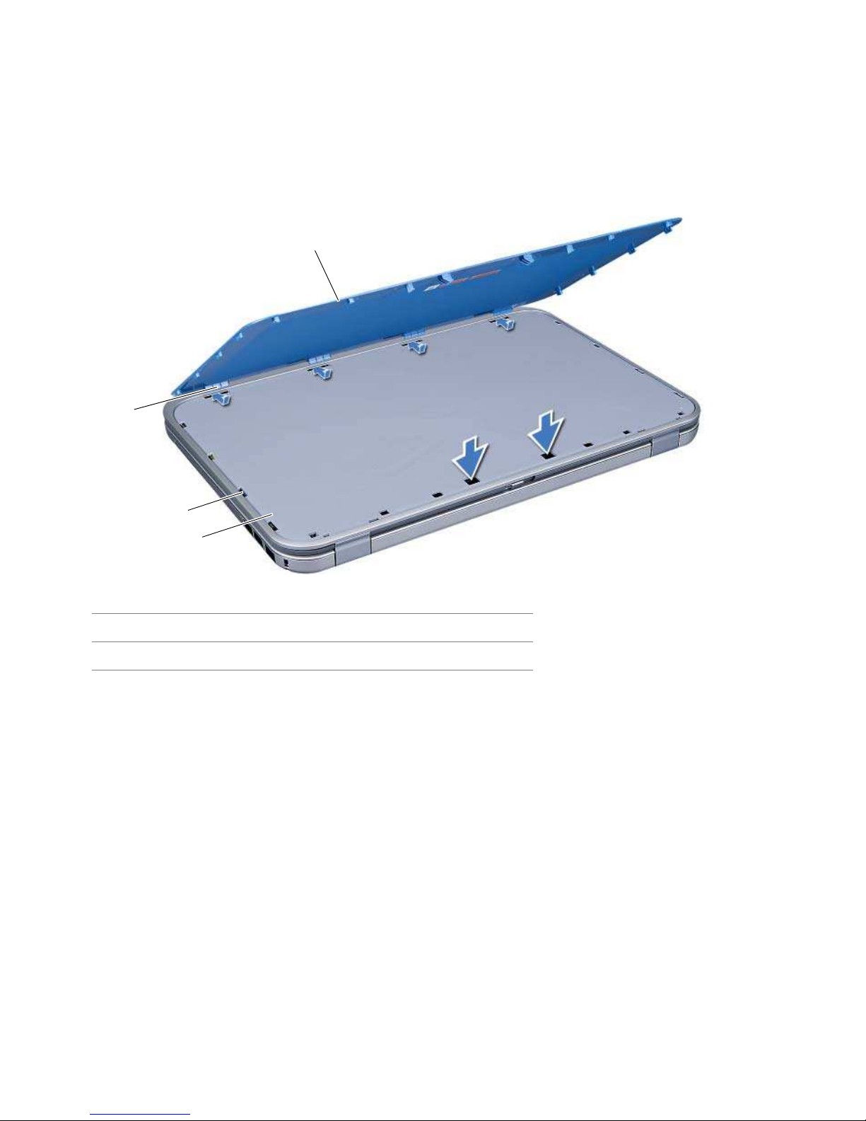
1 Align the tabs at the bottom of the switch with the slots on the display cover and
snap the switch into place.
2 Follow the instructions in "After Working Inside Your Computer" on page 9.
1display cover 2slots
3tabs 4switch
4
1
2
3

Battery | 13
4
Battery
WARNING: Before working inside your computer, read the safety information
that shipped with your computer and follow the steps in "Before You Begin" on
page 7. For additional safety best practices information, see the Regulatory
Compliance Homepage at dell.com/regulatory_compliance.
Removing the Battery
1 Close the display and turn the computer over.
2 Slide the battery release latches to the unlock position.
3 Lift the battery out of the battery bay.
Replacing the Battery
1 Align the tabs on the battery with the slots on the battery bay and snap the battery
until it clicks into place.
2 Follow the instructions in "After Working Inside Your Computer" on page 9.
1 battery release latches (2) 2 battery
1
2

14 | Battery
Keyboard | 15
5
Keyboard
WARNING: Before working inside your computer, read the safety information
that shipped with your computer and follow the steps in "Before You Begin" on
page 7. For additional safety best practices information, see the Regulatory
Compliance Homepage at dell.com/regulatory_compliance.
Removing the Keyboard
Prerequisites
1 Remove the battery. See "Removing the Battery" on page 13.
Procedure
CAUTION: The keycaps on the keyboard are fragile, easily dislodged, and
time-consuming to replace. Be careful when removing and handling the keyboard.
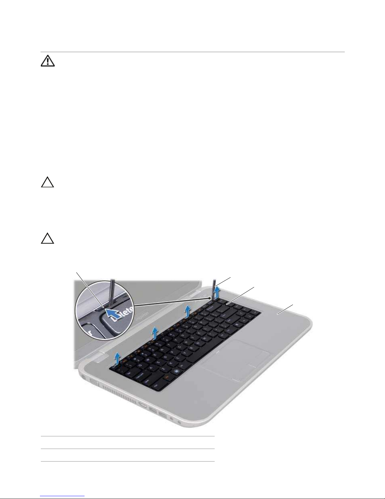
1 Turn the computer over and open the display as far as possible.
2 Using a plastic scribe, release the keyboard from the tabs on the palm rest and ease
the keyboard up until it clears off the palm rest.
CAUTION: Be extremely careful when removing and handling the keyboard.
Failure to do so could result in scratching the display panel.
1 tabs (4) 2 plastic scribe
3 keyboard 4 palm rest
1
2
3
4

16 | Keyboard
3 Carefully turn the keyboard over and place it on the palm rest.
4 Lift the connector latch and pull the pull-tab to disconnect the keyboard cable
from the connector on the system board.
5 Lift the keyboard away from the computer.
Replacing the Keyboard
Procedure
1 Slide the keyboard cable into the connector on the system board and press down
on the connector latch to secure the cable.
2 Slide the tabs at the bottom of the keyboard into the slots on the palm rest and
place the keyboard on the palm rest.
3 Gently press around the edges of the keyboard to secure the keyboard under the
tabs on the palm rest.
4 Close the display and turn the computer over.
Postrequisites
1 Replace the battery. See "Replacing the Battery" on page 13.
2 Follow the instructions in "After Working Inside Your Computer" on page 9.
1 keyboard cable 2 connector latch
3tabs (5)
2
1
3
Base Cover | 17
6
Base Cover
WARNING: Before working inside your computer, read the safety information
that shipped with your computer and follow the steps in "Before You Begin" on
page 7. For additional safety best practices information, see the Regulatory
Compliance Homepage at dell.com/regulatory_compliance.
Removing the Base Cover
Prerequisites
1 Remove the battery. See "Removing the Battery" on page 13.
Procedure
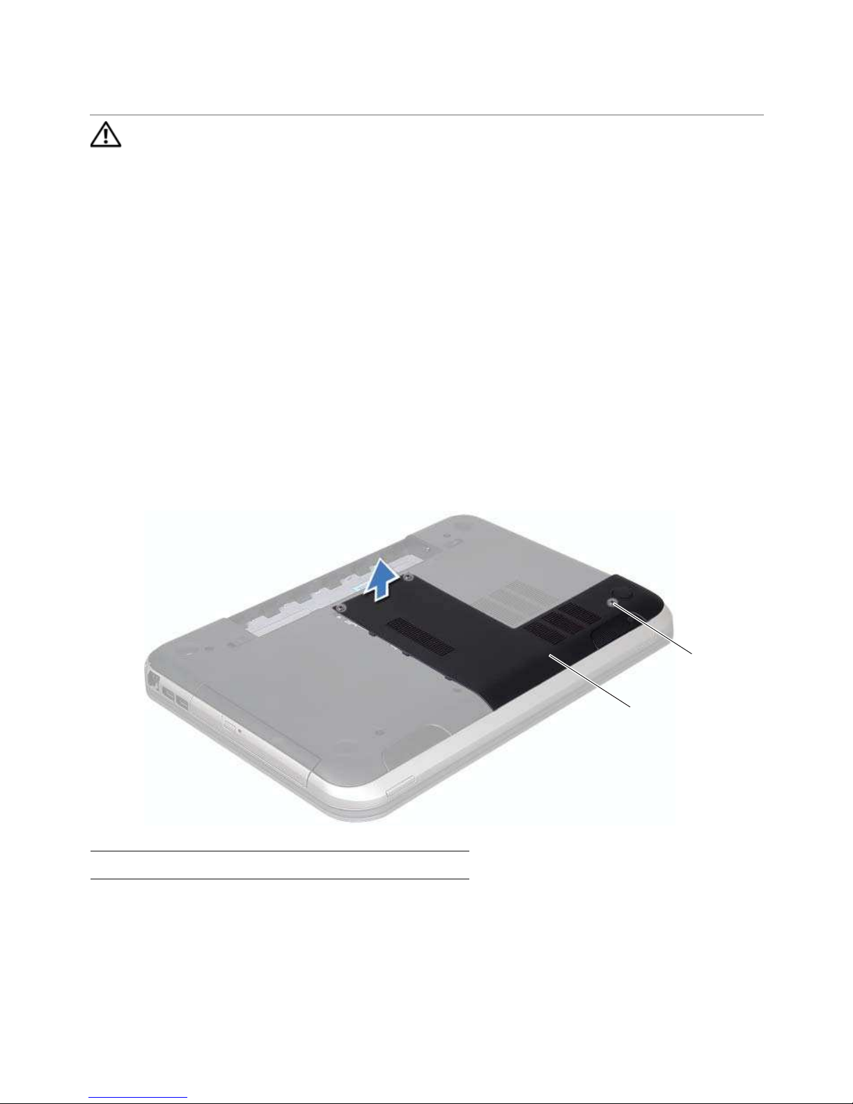
1 Loosen the captive screws that secure the base cover to the computer base.
2 Using your fingertips, pry the base cover from the computer base.
3 Lift the base cover off the computer base.
1 base cover 2 captive screws (3)
1
2

18 | Base Cover
Replacing the Base Cover
Procedure
1 Slide the tabs on the base cover into the slots on the computer base and snap the
base cover into place.
2 Tighten the captive screws that secure the base cover to the computer base.
Postrequisites
1 Replace the battery. See "Replacing the Battery" on page 13.
2 Follow the instructions in "After Working Inside Your Computer" on page 9.
Memory Module(s) | 19
7
Memory Module(s)
WARNING: Before working inside your computer, read the safety information
that shipped with your computer and follow the steps in "Before You Begin" on
page 7. For additional safety best practices information, see the Regulatory
Compliance Homepage at dell.com/regulatory_compliance.
Removing the Memory Module(s)
Prerequisites
1 Remove the battery. See "Removing the Battery" on page 13.
2 Remove the base cover. See "Removing the Base Cover" on page 17.
Procedure
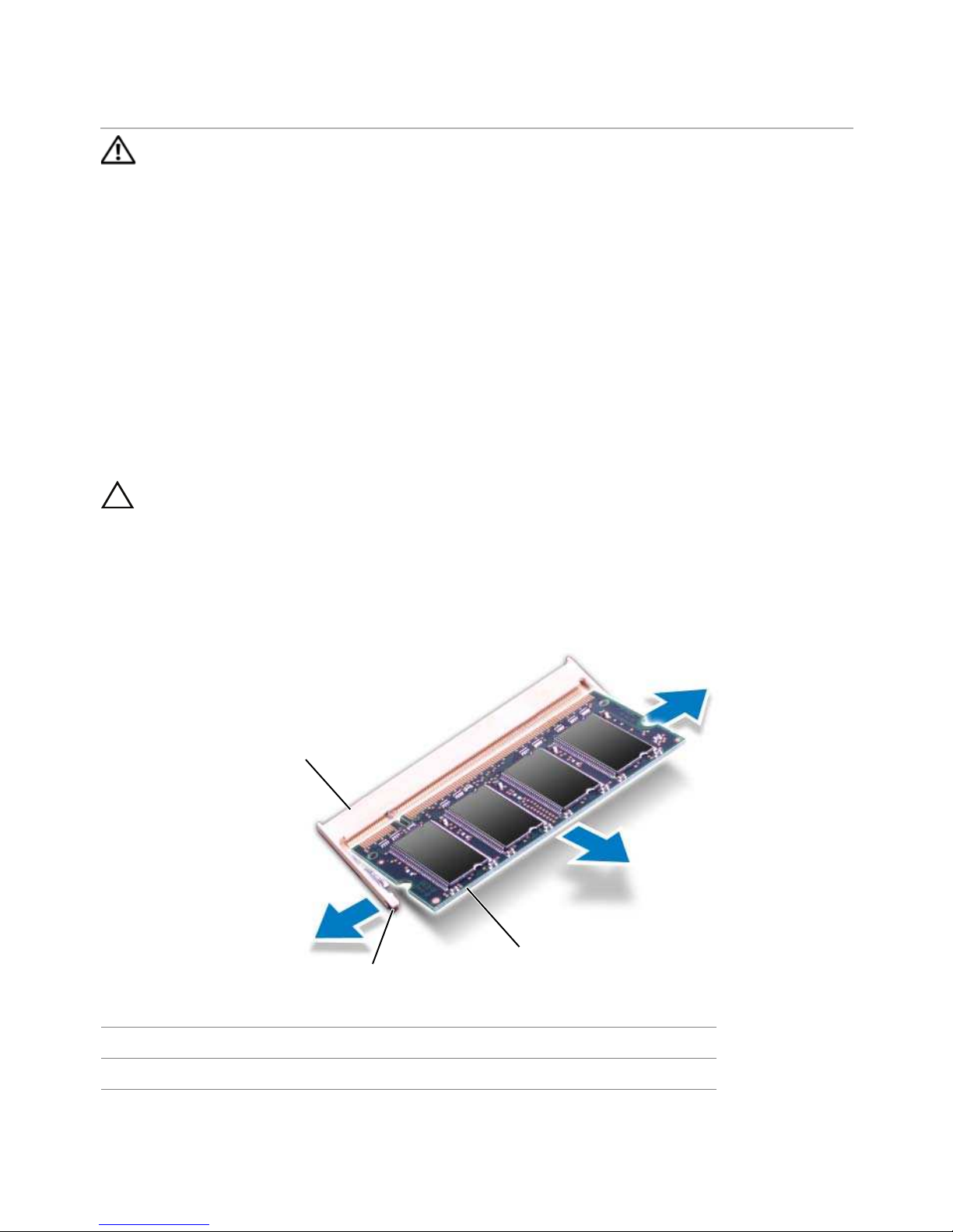
CAUTION: To prevent damage to the memory-module connector, do not use
tools to spread the memory-module securing clips.
1 Use your fingertips to carefully spread apart the securing clips on each end of the
memory-module connector until the memory module pops up.
2 Remove the memory module from the memory-module connector.
1 memory-module connector 2 securing clips (2)
3 memory module
1
2
3
20 | Memory Module(s)
Replacing the Memory Module(s)
Procedure
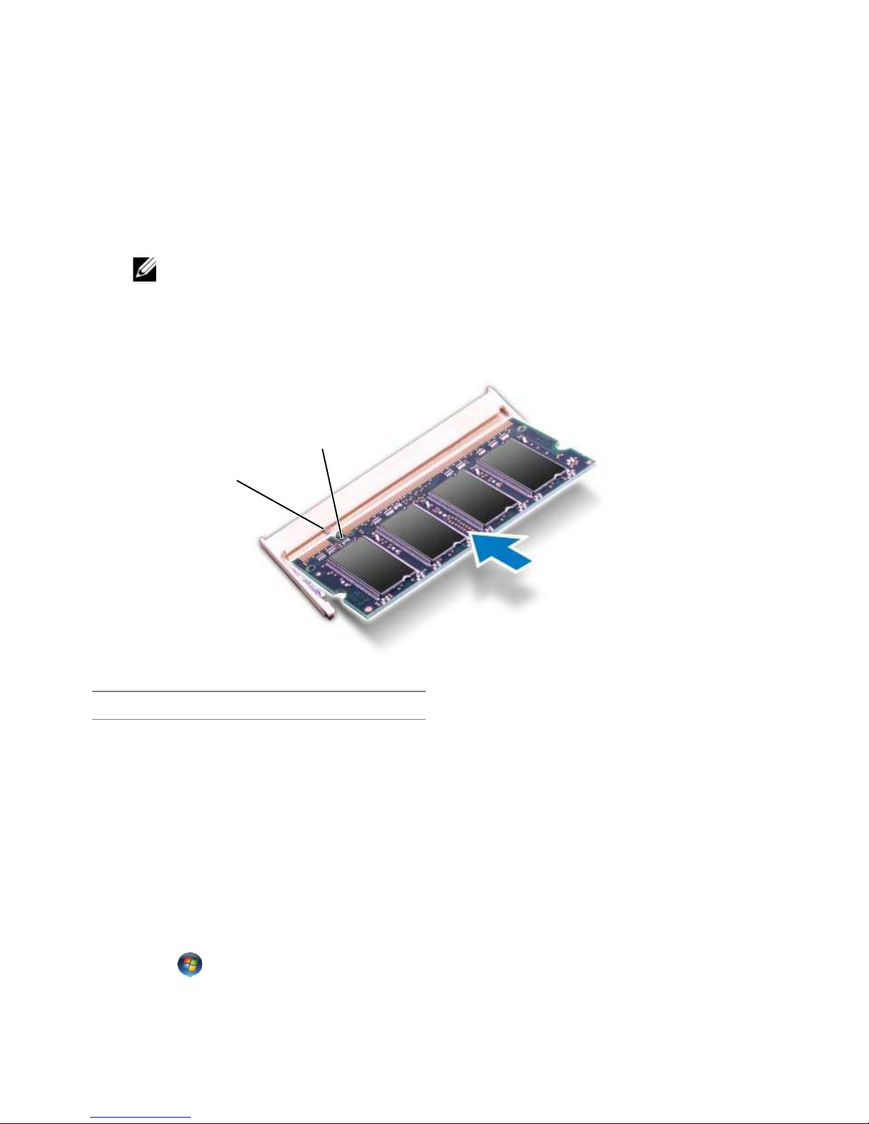
1 Align the notch on the memory module with the tab on the memory-module
connector.
2 Slide the memory module firmly into the slot at a 45-degree angle, and press the
memory module down until it clicks into place. If you do not hear the click, remove
the memory module and reinstall it.
NOTE: If the memory module is not installed properly, the computer may not
boot.
Postrequisites
1 Replace the base cover. See "Replacing the Base Cover" on page 18.
2 Replace the battery. See "Replacing the Battery" on page 13.
3 Follow the instructions in "After Working Inside Your Computer" on page 9.
4 Turn on the computer.
As the computer boots, it detects the memory module(s) and automatically updates the
system configuration information.
To confirm the amount of memory installed in the computer:
Click Start → Control Panel→ System and Security→ System.
1tab 2notch
1
2

Hard Drive | 21
8
Hard Drive
WARNING: Before working inside your computer, read the safety information
that shipped with your computer and follow the steps in "Before You Begin" on
page 7. For additional safety best practices information, see the Regulatory
Compliance Homepage at dell.com/regulatory_compliance.
CAUTION: To avoid data loss, do not remove the hard drive while the computer is
On or in Sleep state.
CAUTION: Hard drives are extremely fragile. Exercise care when handling the
hard drive.
Removing the Hard Drive
Prerequisites
1 Remove the battery. See "Removing the Battery" on page 13.
2 Remove the base cover. See "Removing the Base Cover" on page 17.
22 | Hard Drive
Procedure
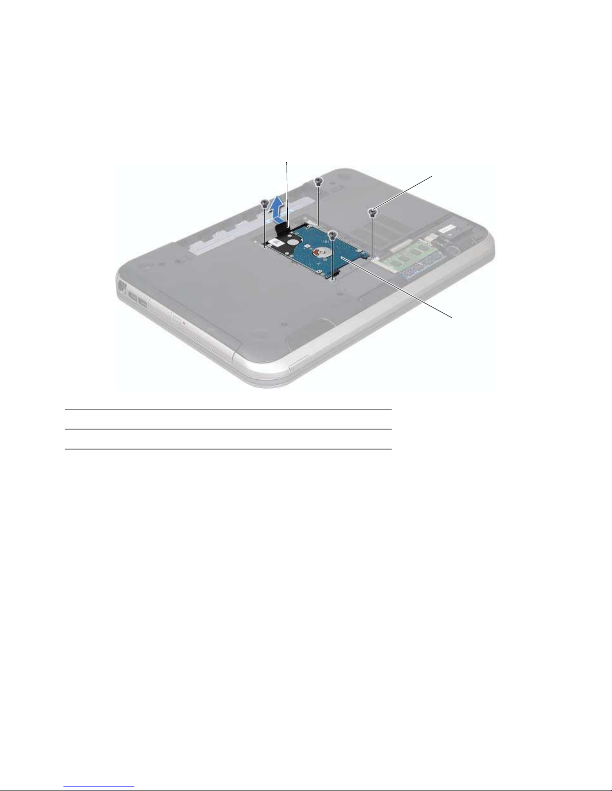
1 Remove the screws that secure the hard-drive assembly to the computer base.
2 Using the pull-tab, slide the hard-drive assembly toward the back of the computer
to disconnect the hard-drive assembly from the connector on the system board.
3 Lift the hard-drive assembly out of the computer base.
1pull-tab 2screws (4)
3 hard-drive assembly
3
2
1

Hard Drive | 23
4 Remove the screws that secure the hard-drive bracket to the hard drive.
5 Lift the hard drive off the hard-drive bracket.
Replacing the Hard Drive
Procedure
1 Remove the new hard drive from its packaging.
Save the original packaging for storing or shipping the hard drive.
2 Align the screw holes on the hard drive-bracket with the screw holes on the hard
drive.
3 Replace the screws that secure the hard-drive bracket to the
hard drive.
4 Place the hard-drive assembly on the computer base.
5 Using the pull-tab, slide the hard-drive assembly toward the front of the computer,
to connect the hard-drive assembly to the connector on the system board.
6 Replace the screws that secure the hard-drive assembly to the computer base.
1screws (4) 2hard drive
3 hard-drive bracket
1
2
3

24 | Hard Drive
Postrequisites
1 Replace the base cover. See "Replacing the Base Cover" on page 18.
2 Replace the battery. See "Replacing the Battery" on page 13.
3 Follow the instructions in "After Working Inside Your Computer" on page 9.

Optical Drive | 25
9
Optical Drive
WARNING: Before working inside your computer, read the safety information
that shipped with your computer and follow the steps in "Before You Begin" on
page 7. For additional safety best practices information, see the Regulatory
Compliance Homepage at dell.com/regulatory_compliance.
Removing the Optical Drive
Prerequisites
1 Remove the battery. See "Removing the Battery" on page 13.
2 Remove the base cover. See "Removing the Base Cover" on page 17.
Procedure
1 Remove the screw that secures the optical-drive assembly to the computer base.
2 Using your fingertips, slide the optical-drive assembly out of the optical-drive bay.
1 optical-drive assembly 2 screw
2
1
 Loading...