

Page 1

Dell Precision 3240 Compact
Setup and Specifications
Reg ula tor y M ode l: D16 S
Reg ula tor y T ype : D 16S 001
Aug ust 20 20
Rev . A 00
Page 2

Notes, cautions, and warnings
NOTE: A NOTE indicates important information that helps you make better use of your product.
CAUTION: A CAUTION indicates either potential damage to hardware or loss of data and tells you how to avoid
the problem.
WARNING: A WARNING indicates a potential for property damage, personal injury, or death.
© 2020 Dell Inc. or its subsidiaries. All rights reserved. Dell, EM C, and other trademarks are trademarks of Dell Inc. or its subsidiaries. Oth er
trademarks may be trademarks of their respective owners.
Page 3

Contents
Chapter 1: Set up your computer................................................................................................... 5
Chapter 2: Views of Precision 3240 Compact............................................................................... 10
Front......................................................................................................................................................................................10
Back........................................................................................................................................................................................11
Side........................................................................................................................................................................................12
Chapter 3: Specifications of Precision 3240 Compact.................................................................. 13
System specifications....................................................................................................................................................... 13
Dimensions and weight............................................................................................................................................... 13
Processors..................................................................................................................................................................... 13
Chipset............................................................................................................................................................................14
Operating system......................................................................................................................................................... 14
Memory...........................................................................................................................................................................15
Ports and connectors..................................................................................................................................................15
Ethernet..........................................................................................................................................................................16
Wireless module............................................................................................................................................................16
Audio................................................................................................................................................................................ 17
Storage............................................................................................................................................................................17
Power adapter...............................................................................................................................................................18
GPU—Integrated......................................................................................................................................................... 18
GPU—Discrete............................................................................................................................................................. 18
Add-in cards.................................................................................................................................................................. 19
Regulatory......................................................................................................................................................................19
Data security................................................................................................................................................................. 19
Operating and storage environment....................................................................................................................... 20
Chapter 4: System setup............................................................................................................. 21
BIOS overview.................................................................................................................................................................... 21
Entering BIOS setup program................................................................................................................................... 21
Boot menu......................................................................................................................................................................21
Navigation keys.................................................................................................................................................................. 21
Boot Sequence...................................................................................................................................................................22
System setup options.......................................................................................................................................................22
General options............................................................................................................................................................ 22
System information.....................................................................................................................................................23
Video screen options.................................................................................................................................................. 24
Security.......................................................................................................................................................................... 24
Secure boot options....................................................................................................................................................25
Intel Software Guard Extensions options.............................................................................................................. 26
Performance................................................................................................................................................................. 26
Power management.................................................................................................................................................... 27
Post behavior................................................................................................................................................................28
Manageability................................................................................................................................................................29
Contents 3
Page 4

Virtualization support................................................................................................................................................. 29
Wireless options...........................................................................................................................................................29
Maintenance................................................................................................................................................................. 30
System logs...................................................................................................................................................................30
Advanced configuration............................................................................................................................................. 30
SupportAssist System Resolution............................................................................................................................ 31
Updating the BIOS in Windows ..................................................................................................................................... 31
Updating BIOS on systems with BitLocker enabled............................................................................................32
Updating your system BIOS using a USB flash drive..........................................................................................32
System and setup password...........................................................................................................................................33
Assigning a system setup password....................................................................................................................... 33
Deleting or changing an existing system setup password................................................................................. 33
Clearing BIOS (System Setup) and System passwords...........................................................................................34
Chapter 5: Software....................................................................................................................35
Downloading Windows drivers....................................................................................................................................... 35
Chapter 6: Getting help and contacting Dell................................................................................ 36
4 Contents
Page 5
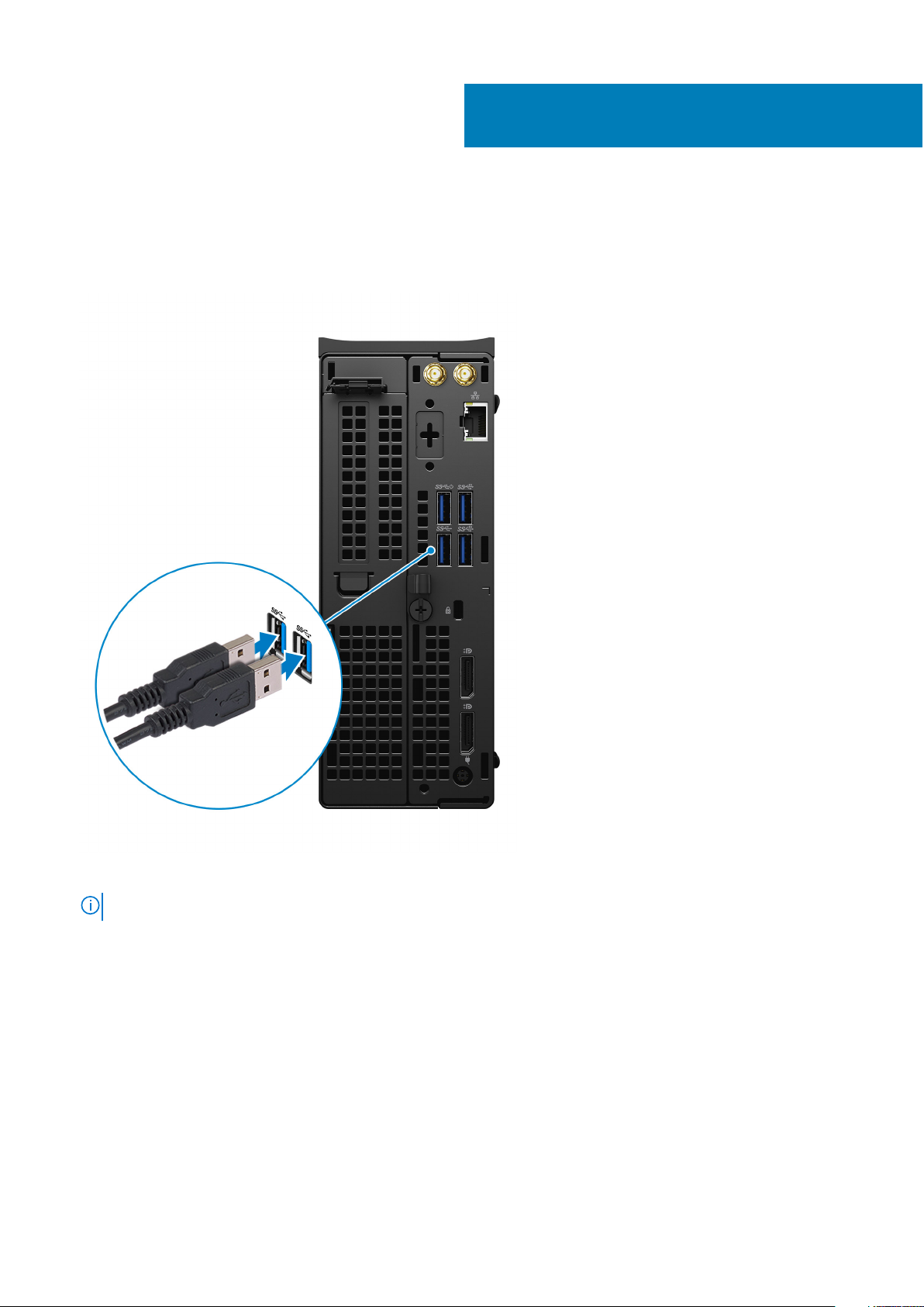
Steps
1. Connect the keyboard and mouse.
1
Set up your computer
2. Connect to your network using a cable, or connect to a wireless network.
NOTE: The wireless network card is optional and needs to be purchased separately.
Set up your computer 5
Page 6
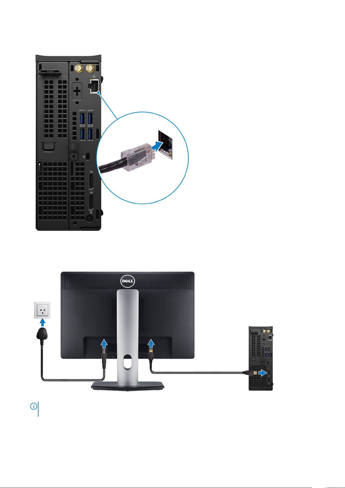
3. Connect the display.
NOTE:
If you ordered the computer with a discrete graphics card, the HDMI and the display ports on the back panel of
the computer are covered. Connect the display to the discrete graphics card.
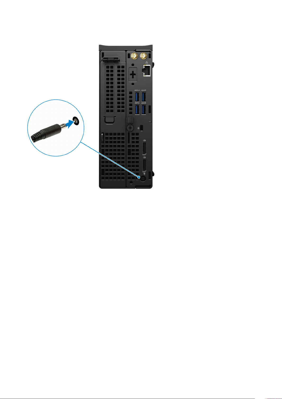
4. Connect the power adapter.
6
Set up your computer
Page 7
5. Press the power button.
Set up your computer
7
Page 8
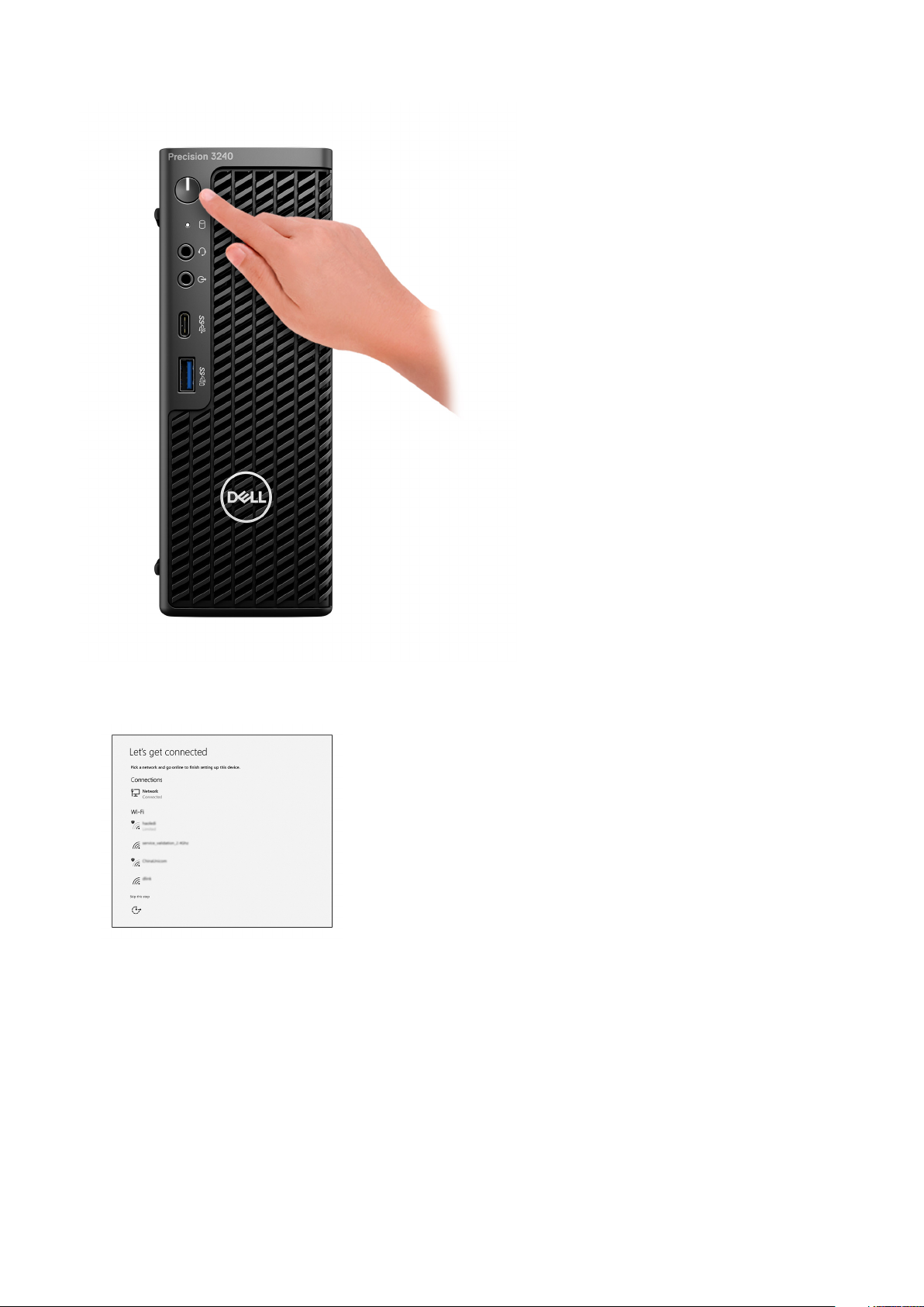
6. Follow the instructions on the screen to finish Windows setup:
a. Connect to a network.
b. Sign-in to your Microsoft account or create a new account.
8
Set up your computer
Page 9
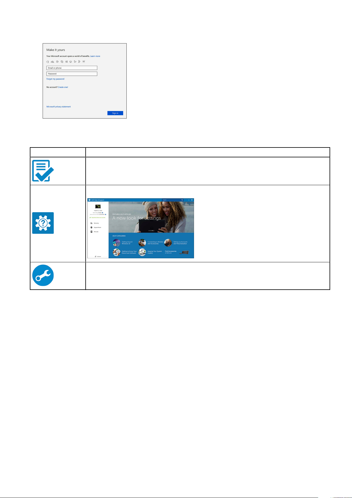
7. Locate Dell apps.
Table 1. Locate Dell apps
Icons Functions
Register your computer
Dell Help & Support
SupportAssist — Check and update your computer
Set up your computer 9
Page 10
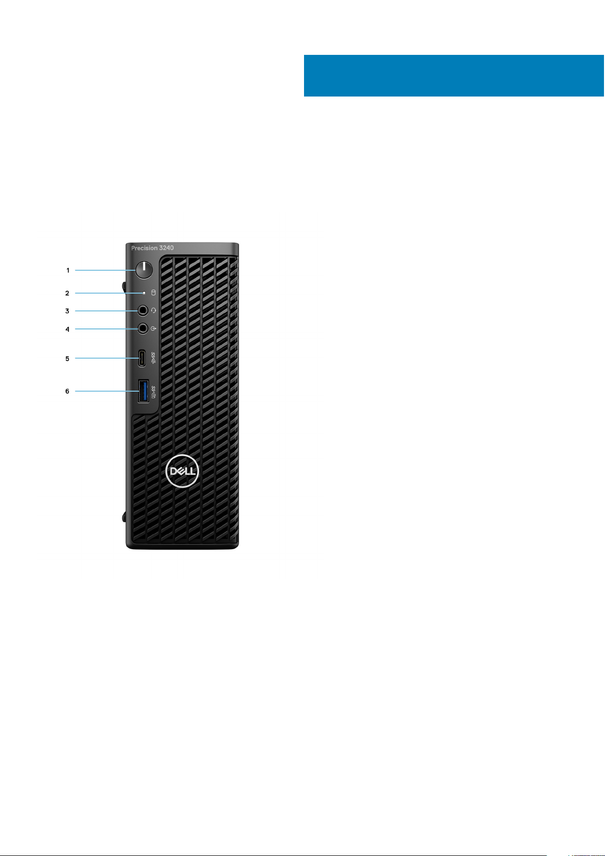
Front
2
Views of Precision 3240 Compact
1. Power button (Diagnostics indicator)
2. Storage activity LED
3. Headset port
4. Line-out/Line-in audio port
5. USB 3.2 Type-C Gen 2 (10 Gbps)
6. USB 3.2 Type-A Gen 2 (10 Gbps), with PowerShare
10 Views of Precision 3240 Compact
Page 11
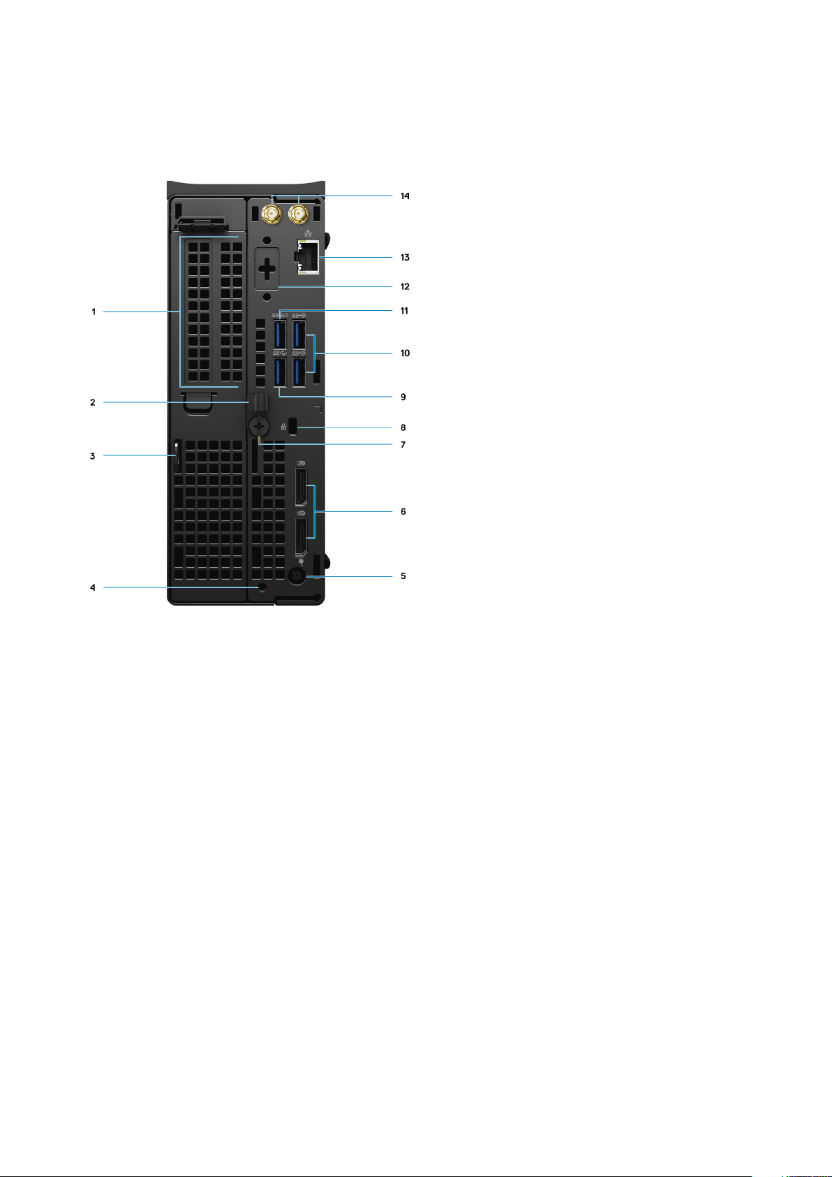
Back
1. Expansion card slot
2. Cable management bracket
3. Padlock hoop
4. Mounting screw hole
5. Power adapter port
6. Two DisplayPort 1.4
7. Thumbscrew
8. Kensington cable lock slot
9. USB 3.2 Type-A Gen 1 (5 Gbps)
10. Two USB 3.2 Type-A Gen 2 (10 Gbps)
11. USB 3.2 Type-A Gen 1 (5 Gbps), with SmartPower
12. Optional Port (VGA, HDMI 2.0, DisplayPort++ 1.4, USB Type-C with DP 1.4-alt mode)
13. RJ45 Network Connector
14. Integrated external SMA antenna connectors (Optional)
Views of Precision 3240 Compact
11
Page 12
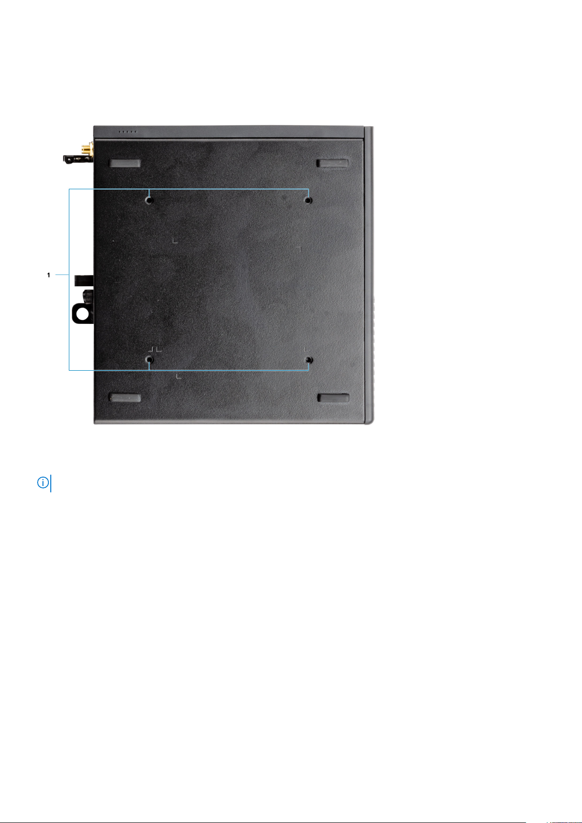
Side
1. Four M4x10 screw posts for VESA mounting options.
NOTE: The Dell Precision 3240 Compact system has screw holes 100 mmx100 mm apart.
12 Views of Precision 3240 Compact
Page 13
Specifications of Precision 3240 Compact
System specifications
NOTE: Offerings may vary by region. The following specifications are only those required by law to ship with your
computer. For more information about the configuration of your computer, go to Help and Support in your Windows
operating system and select the option to view information about your computer.
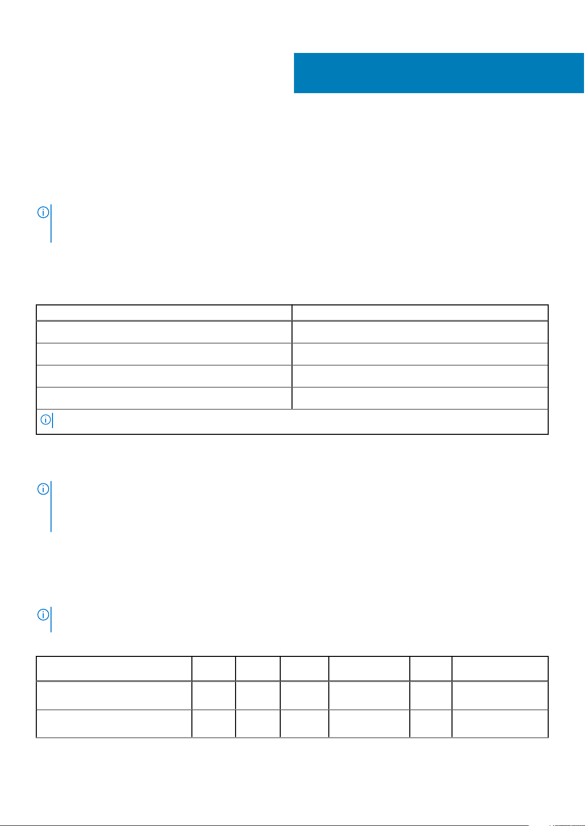
Dimensions and weight
Table 2. Dimensions and weight
Description Values
3
Height
Width
Depth
Weight (approximate)
NOTE: The weight of your system unit varies depending on the configuration ordered and the manufacturing variability.
188.10 mm (7.40 in.)
70.20 mm (2.76 in.)
178.65 mm (7.03 in.)
1.71 kg (3.77 lb)
Processors
NOTE:
Global Standard Products (GSP) are a subset of Dell’s relationship products that are managed for availability and
synchronized transitions on a worldwide basis. They ensure the same platform is available for purchase globally. This allows
customers to reduce the number of configurations managed on a worldwide basis, thereby reducing their costs. They also
enable companies to implement global IT standards by locking in specific product configurations worldwide.
Device Guard (DG) and Credential Guard (CG) are the new security features that are only available on Windows 10 Enterprise
today. Device Guard is a combination of enterprise-related hardware and software security features. When you configure them
together, it locks a device down so that it can only run trusted applications. Credential Guard uses virtualization-based security
to isolate secrets (credentials) so that only privileged system software can access them. Unauthorized access to these secrets
can lead to credential theft attacks. Credential Guard prevents these attacks by protecting NT LAN Manager (NTLM) password
hashes and Kerberos Ticket Granting Tickets.
Processor numbers are not a measure of performance. Processor availability is subject to change and may vary by
NOTE:
region/country.
Table 3. Processors
Processors WattageCore
count
10th Generation Intel Core i3-10100 65 W 4 8 3.6 GHz to 4.3
10th Generation Intel Core i5-10500 65 W 6 12 3.1 GHz to 4.5
Thread
count
Speed
GHz
GHz
Specifications of Precision 3240 Compact 13
Cache Integrated graphics
6 MB Intel UHD Graphics
630
12 MB Intel UHD Graphics
630
Page 14
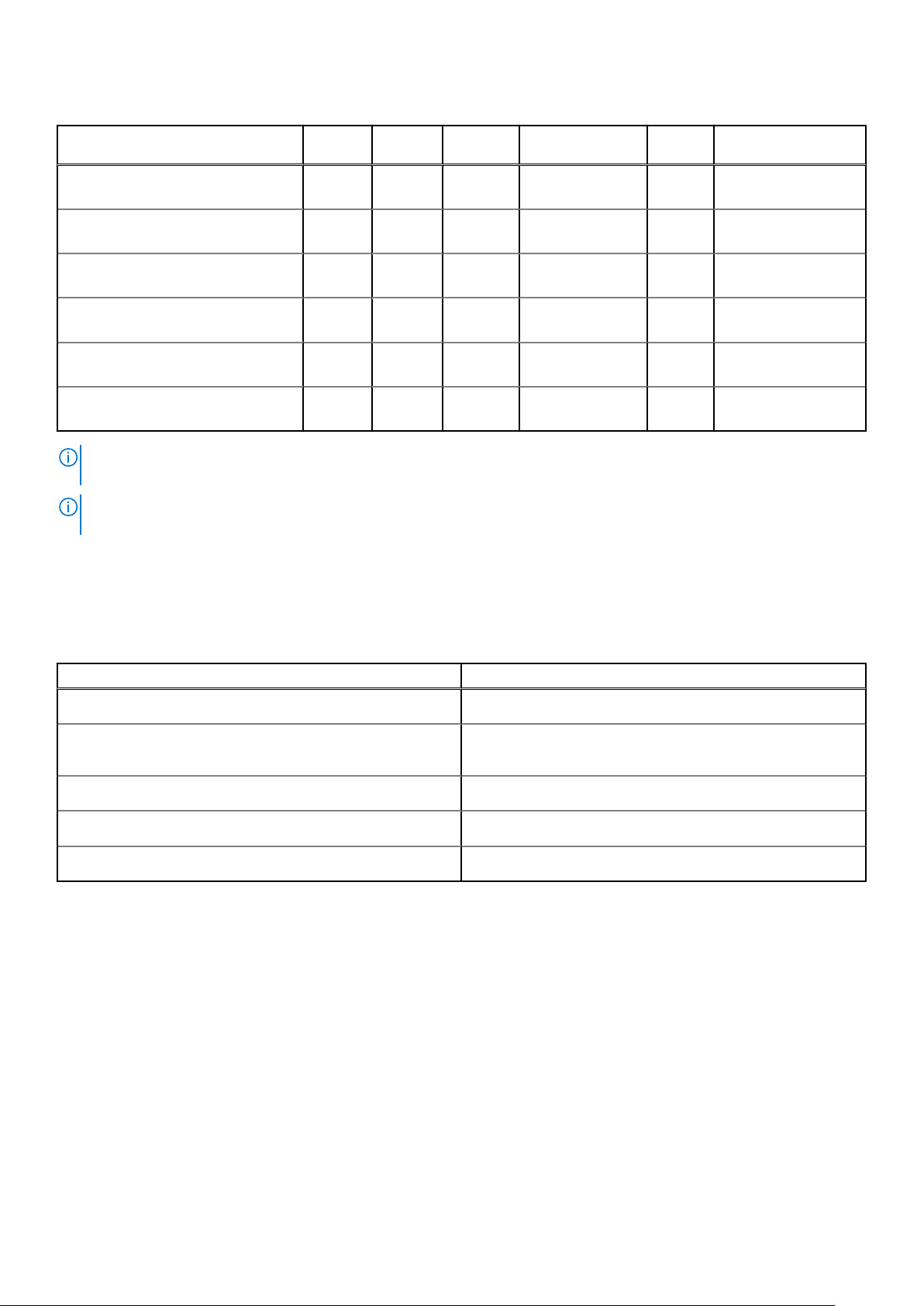
Table 3. Processors (continued)
Processors WattageCore
count
10th Generation Intel Core i5-10600 65 W 6 12 3.3 GHz to 4.8
10th Generation Intel Core i7-10700 65 W 8 16 2.9 GHz to 4.7
10th Generation Intel Core i9-10900 65 W 10 20 2.8 GHz to 5.2
10th Generation Intel Xeon W-1250 80 W 6 12 3.3 GHz to 4.7
10th Generation Intel Xeon W-1270 80 W 8 16 3.4 GHz to 4.9
10th Generation Intel Xeon W-1290 80 W 10 20 3.2 GHz to 5.2
NOTE: 10th Generation Intel Core i3-10100, i5-10500, i5-10600 and, Xeon W-1250 processors supports the shipped 3200
MHz memory at 2666 MHz.
NOTE: 10th Generation Intel Core i7-10700, i9-10900, W-1270 and, W-1290 processors supports the shipped 3200 MHz
memory at 2933 MHz.
Thread
count
Speed
GHz
GHz
GHz
GHz
GHz
GHz
Cache Integrated graphics
12 MB Intel UHD Graphics
630
16 MB Intel UHD Graphics
630
20 MB Intel UHD Graphics
630
12 MB Intel UHD Graphics
P630
16 MB Intel UHD Graphics
P630
20 MB Intel UHD Graphics
P630
Chipset
The following table lists the details of the chipset supported by your Precision 3240 Compact.
Table 4. Chipset
Description Values
Chipset
Processor
DRAM bus width
Flash EPROM
PCIe bus
Intel W480 PCH
10th Generation Intel Core i3/i5/i7/i9 and Xeon W-series
processors
64-bit
32 MB
Up to Gen 3.0
Operating system
Your Precision 3240 Compact supports the following operating systems:
● Windows 10 Home (64-bit)
● Windows 10 Pro (64-bit)
● Windows 10 Pro (64-bit) National Academic
● Windows 10 Pro Workstation (64-bit)
● Windows 10 IoT Enterprise 2019, LTSC
● Ubuntu Linux 18.04 SP1
14
Specifications of Precision 3240 Compact
Page 15
Memory
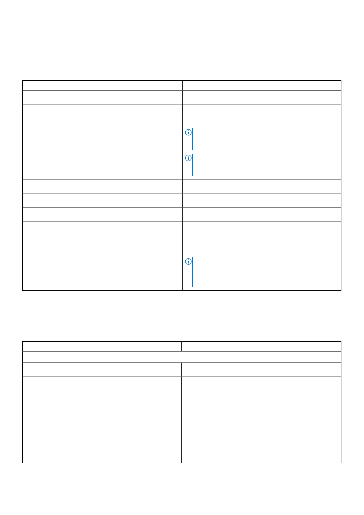
The following table lists the memory specifications of your Precision 3240 Compact.
Table 5. Memory specifications
Description Values
Memory slots
Memory type
Memory speed
Maximum memory configuration
Minimum memory configuration
Memory size per slot
Memory configurations supported
Two-SODIMM slots
Single-channel DDR4
3200 MHz
NOTE: 10th Generation Intel Core i3-10100, i5-10500,
i5-10600 and, Xeon W-1250 processors supports the
shipped 3200 MHz memory at 2666 MHz.
NOTE: 10th Generation Intel Core i7-10700, i9-10900,
W-1270 and, W-1290 processors supports the shipped
3200 MHz memory at 2933 MHz.
64 GB
8 GB
8 GB, 16 GB, 32 GB
● 8 GB = 2 x 4 GB or 1 x 8 GB
● 16 GB = 2 x 8 GB or 1 x 16 GB
● 32 GB = 1 x 32 GB or 2 x 16 GB
● 64 GB = 2 x 32 GB
NOTE: A multiple DIMM memory option is recommended
to prevent any performance reduction. If the system
configuration includes integrated graphics, consider
selecting 2 or more DIMMs
Ports and connectors
The following table lists the external and internal ports available on your Precision 3240 Compact.
Table 6. Ports and connectors
Description Values
External:
Network
USB
One RJ-45 port
● Front:
○ One USB 3.2 Type A Gen 2 (10 Gbps), with
PowerShare
○ One USB 3.2 Type C Gen 2 (10 Gbps)
● Rear:
○ One USB 3.2 Type A Gen 1 (5 Gbps)
○ One USB 3.2 Type A Gen 1 (5 Gbps), with SmartPower
○ Two USB 3.2 Type A Gen 2 (10 Gbps)
Specifications of Precision 3240 Compact 15
Page 16
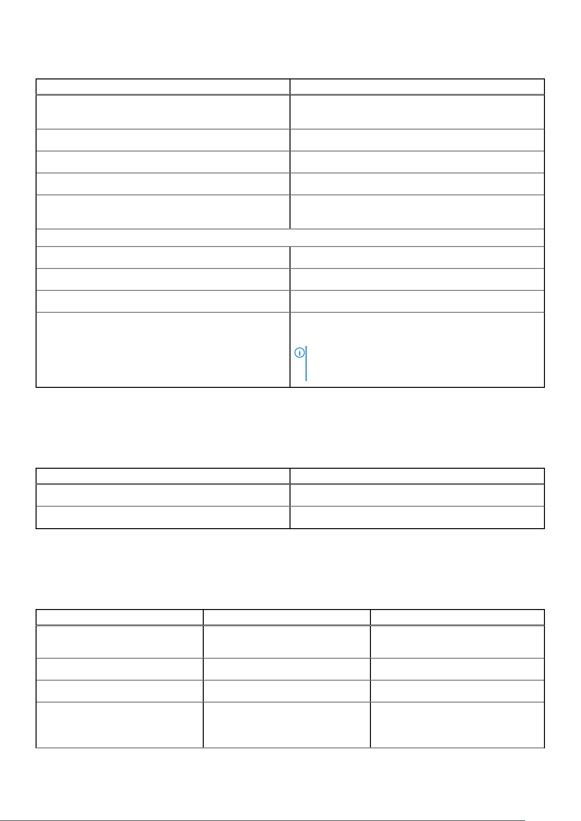
Table 6. Ports and connectors (continued)
Description Values
Audio
Video
Media-card reader
Power port
Security
Internal:
PCIe expansion card slots
mSATA
SATA
M.2
● One Line-out/Line-in audio port
● One 3.5 mm headset port
Two DisplayPort 1.4
Not supported
7.4 mm DC barrel-type
● One Kensington security-cable slot
● One Padlock hoop
One Half-height Gen 3 PCIe x8 slot
Not supported
One SATA slot for 2.5-inch HDD
● One M.2 2230 slot for WiFi/Bluetooth combo card
● Two M.2 2230/2280 slot for PCIe solid-state drive
NOTE: To learn more about the features of different
types of M.2 cards, see the knowledge base article
SLN301626.
Ethernet
The following table lists the wired Ethernet Local Area Network (LAN) specifications of your Precision 3240 Compact.
Table 7. Ethernet specifications
Description Values
Model number
Transfer rate
Intel i219-LM
10/100/1000 Mbps
Wireless module
The following table lists the Wireless Local Area Network (WLAN) modules supported on your Precision 3240 Compact.
Table 8. Wireless module specifications
Description Option one Option two
Model number
Transfer rate
Frequency bands supported
Qualcomm QCA61x4A (DW1820) with
Bluetooth 5.1
Up to 867 Mbps Up to 2400 Mbps
2.4 GHz/5 GHz 2.4 GHz /5 GHz
Intel Wi-Fi 6, AX201, 2x2, 802.11ax with
Bluetooth 5.1
Wireless standards
16 Specifications of Precision 3240 Compact
● WiFi 802.11a/b/g
● Wi-Fi 4 (WiFi 802.11n)
● Wi-Fi 5 (WiFi 802.11ac)
● WiFi 802.11a/b/g
● Wi-Fi 4 (WiFi 802.11n)
Page 17

Table 8. Wireless module specifications (continued)
Description Option one Option two
● Wi-Fi 5 (WiFi 802.11ac)
● Wi-Fi 6 (WiFi 802.11ax)
Encryption
Bluetooth
● 64-bit/128-bit WEP
● AES-CCMP
● TKIP
Bluetooth 5.1 Bluetooth 5.1
Audio
The following table lists the audio specifications of your Precision 3240 Compact.
Table 9. Audio specifications
Description Values
Audio type
Audio controller
Internal audio interface
External audio interface
High Definition (HD) Audio
Realtek ALC3246
HD audio interface
Universal Audio Jack and One Line-out port (re-taskable Linein)
● 64-bit/128-bit WEP
● AES-CCMP
● TKIP
Storage
This section lists the storage options on your Precision 3240 Compact.
Your computer supports one of the following configurations:
● One 2.5-inch hard-disk drive (HDD)
● Two M.2 2230/2280 Solid-State Drive (SSD)
The primary drive of your computer varies with the storage configuration. For computers:
● with a M.2 SSD drive, the SSD is the primary drive
● without a M.2 SSD drive, the 2.5-inch HDD is the primary drive
Table 10. Storage specifications
Storage type Interface type Capacity
2.5-inch, 5400 RPM, HDD SATA 3.0 AHCI, up to 6 Gbps Up to 2 TB
2.5-inch, 7200 RPM, HDD SATA 3.0 AHCI, up to 6 Gbps Up to 1 TB
2.5-inch, 7200 RPM, FIPS Self
Encrypting Opal 2.0, HDD
M.2 2280 SSD Gen 3 PCIe x4 NVMe, Class 40 Up to 2 TB
M.2 2280 SSD Gen 3 PCIe x4 NVMe, Class 50 Up to 1 TB
SATA 3.0 AHCI, up to 6 Gbps Up to 512 GB
M.2 2280 SSD, self-encrypting drive Gen 3 PCIe x4 NVMe, Class 40 Up to 1 TB
Specifications of Precision 3240 Compact 17
Page 18

Power adapter
The following table lists the power adapter specifications of your Precision 3240 Compact.
Table 11. Power adapter specifications
Description Option one Option two
Type
Connector dimensions:
External diameter
Internal diameter
Input voltage
Input frequency
Input current (maximum)
Output current (continuous)
Rated output voltage
Temperature range:
Operating
Storage
180 W 240 W (required for Xeon and discrete
graphics card configurations)
7.40 mm (0.29 in.) 7.40 mm (0.29 in.)
5.10 mm (0.20 in.) 5.10 mm (0.20 in.)
100 VAC or 240 VAC 100 V VAC or 240 V VAC
50 Hz or 60 Hz 50 Hz or 60 Hz
2.34 A 3.5 A or 5 A
9.23 A 12.31 A
19.50 VDC 19.5 VDC
0 °C to 40 °C (32 °F to 104 °F) 0 °C to 40 °C (32 °F to 104 °F)
40 °C to -40 °C (104 °F to -40 °F) 40 °C to -40 °C (104 °F to -40 °F)
GPU—Integrated
The following table lists the specifications of the integrated Graphics Processing Unit (GPU) supported by your Precision 3240
Compact.
Table 12. GPU—Integrated
Controller External display support Memory size Processor
Intel UHD Graphics 630 Two DisplayPort 1.4 Shared system memory 10th Generation Intel Core
i3/i5/i7/i9 processors
Intel UHD Graphics P630 Two DisplayPort 1.4 Shared system memory 10th Generation Intel Xeon
W-series processor
GPU—Discrete
The following table lists the specifications of the discrete Graphics Processing Unit (GPU) supported by your Precision 3240
Compact.
Table 13. GPU—Discrete
Controller External display support Memory size
NVIDIA Quadro P1000 Four Mini-DisplayPort 1.4 4 GB
NVIDIA Quadro P620 Four Mini-DisplayPort 1.4 2 GB
18 Specifications of Precision 3240 Compact
Page 19

Table 13. GPU—Discrete (continued)
Controller External display support Memory size
NVIDIA Quadro P400 Three Mini-DisplayPort 1.4 2 GB
NVIDIA Quadro RTX3000 (coming soon) Four Mini-DisplayPort 1.4 6 GB
Add-in cards
Table 14. Add-in cards
Add-in cards
Dell Ultra Speed Drive
2.5/5.0GbE NIC (Aquantia) add-in card
Intel Ethernet server adapter I210-T1
USB 3.2 Type-C PCIe card
USB 3.2 Gen 1 PCIe card
Powered Serial PCIe add-in card
ThunderBolt 3.0 - Dual port with DP 1.4 loopback
Regulatory
Table 15. Regulatory compliance
Features Specifications
ENERGY STAR 8.0 qualified Compliant
EPEAT Gold Registered available in select configurations and regions only
China CECP Compliant
China RoHS Compliant
TCO 8.0 available in select configurations and regions only
China CEL Compliant
WEEE Compliant
Japan Energy Law Compliant
South Korea E-standby Compliant
EU RoHS Compliant
Data security
Table 16. Data security
Data security options Values
Dell Data Protection—Endpoint Security Suite and Endpoint
Security Suite Enterprise
Dell Data Protection—Software Encryption Supported
Dell Data Protection—External Media Encryption Not supported
Supported
Specifications of Precision 3240 Compact 19
Page 20

Table 16. Data security (continued)
Data security options Values
Windows 10 Device Guard and Credential Guard (Enterprise
SKU)
Microsoft Windows BitLocker Supported
Local hard drive data wipe through BIOS (secure erase) Supported
FIPS Self-Encrypting Opal 2.0 hard drive Supported
Dell Data Guardian Supported
Supported
Operating and storage environment
This table lists the operating and storage specifications of your Precision 3240 Compact.
Airborne contaminant level: G1 as defined by ISA-S71.04-1985
Table 17. Computer environment
Description Operating Storage
Temperature range
Relative humidity (maximum)
Vibration (maximum)
Shock (maximum)
*
0°C to 35°C (32°F to 95°F) -40°C to 65°C (-40°F to 149°F)
10% to 90% (non-condensing) 0% to 95% (non-condensing)
0.66 GRMS 1.3 GRMS
110 G† 160 G†
Altitude range
* M eas ure d u sin g a ra ndo m v ibr ati on spectrum that simulates user en vir onm ent .
† M eas ure d u sin g a 2 ms hal f-s ine pulse when the hard drive is i n u se.
-15.2 m to 3048 m (4.64 ft to 5518.4 ft) -15.2 m to 10668 m (4.64 ft to 19234.4
ft)
20
Specifications of Precision 3240 Compact
Page 21

4
System setup
CAUTION: Unless you are an expert computer user, do not change the settings in the BIOS Setup program.
Certain changes can make your computer work incorrectly.
NOTE: Before you change BIOS Setup program, it is recommended that you write down the BIOS Setup program screen
information for future reference.
Use the BIOS Setup program for the following purposes:
● Get information about the hardware installed in your computer, such as the amount of RAM and the size of the hard drive.
● Change the system configuration information.
● Set or change a user-selectable option, such as the user password, type of hard drive installed, and enabling or disabling
base devices.
BIOS overview
The BIOS manages data flow between the computer's operating system and attached devices such as hard disk, video adapter,
keyboard, mouse, and printer.
Entering BIOS setup program
About this task
Turn on (or restart) your computer and press F2 immediately.
Boot menu
Press <F12> when the Dell logo appears to initiate a one-time boot menu with a list of the valid boot devices for the system.
Diagnostics and BIOS Setup options are also included in this menu. The devices listed on the boot menu depend on the bootable
devices in the system. This menu is useful when you are attempting to boot to a particular device or to bring up the diagnostics
for the system. Using the boot menu does not make any changes to the boot order stored in the BIOS.
The options are:
● UEFI Boot:
○ Windows Boot Manager
● Other Options:
○ BIOS Setup
○ BIOS Flash Update
○ Diagnostics
○ Change Boot Mode Settings
Navigation keys
For most of the System Setup options, changes that you make are recorded but do not take effect until you restart
NOTE:
the system.
System setup 21
Page 22

Keys Navigation
Up arrow Moves to the previous field.
Down arrow Moves to the next field.
Enter Selects a value in the selected field (if applicable) or follow the link in the field.
Spacebar Expands or collapses a drop-down list, if applicable.
Tab Moves to the next focus area.
Esc Moves to the previous page until you view the main screen. Pressing Esc in the main screen displays a
message that prompts you to save any unsaved changes and restarts the system.
Boot Sequence
Boot Sequence allows you to bypass the System Setup–defined boot device order and boot directly to a specific device (for
example: optical drive or hard drive). During the Power-on Self Test (POST), when the Dell logo appears, you can:
● Access System Setup by pressing F2 key
● Bring up the one-time boot menu by pressing F12 key
The one-time boot menu displays the devices that you can boot from including the diagnostic option. The boot menu options
are:
● Removable Drive (if available)
● STXXXX Drive (if available)
NOTE: XXX denotes the SATA drive number.
● Optical Drive (if available)
● SATA Hard Drive (if available)
● Diagnostics
NOTE: Choosing Diagnostics, will display the diagnostics screen.
The boot sequence screen also displays the option to access the System Setup screen.
System setup options
NOTE: Depending on the and its installed devices, the items listed in this section may or may not appear.
General options
Table 18. General
Option Description
System Information Displays the following information:
● System Information: Displays BIOS Version, Service Tag, Asset Tag, Ownership Tag,
Manufacture Date, Ownership Date, and the Express Service Code.
● Memory Information: Displays Memory Installed, Memory Available, Memory Speed,
Memory Channel Mode, Memory Technology, DIMM 1 Size, and DIMM 2 Size.
● PCI Information: Displays Slot1_M.2, Slot2_M.2, Slot3_M.2
● Processor Information: Displays Processor Type, Core Count, Processor ID, Current
Clock Speed, Minimum Clock Speed, Maximum Clock Speed, Processor L2 Cache,
Processor L3 Cache, HT Capable, and 64-Bit Technology.
● Device Information: Displays SATA-0, M.2 PCIe SSD-2, LOM MAC Address, Video
Controller, Audio Controller, Wi-Fi Device, and Bluetooth Device.
Boot Sequence Allows you to specify the order in which the computer attempts to find an operating system
from the devices specified in this list.
22 System setup
Page 23

Table 18. General (continued)
Option Description
UEFI Boot Path Security This option controls whether or not the system prompts the user to enter the Admin
password when booting a UEFI boot path from the F12 Boot Menu.
Date/Time Allows you to set the date and time settings. Changes to the system date and time take
effect immediately.
.
System information
Table 19. System Configuration
Option Description
Integrated NIC Allows you to control the onboard LAN controller. The option ‘Enable UEFI Network Stack’ is
not selected by default. The options are:
● Disabled
● Enabled
● Enabled w/PXE (default)
NOTE: Depending on the computer and its installed devices, the items that are listed in
this section may or may not appear.
SATA Operation Allows you to configure the operating mode of the integrated hard drive controller.
● Disabled = The SATA controllers are hidden
● AHCI = SATA is configured for AHCI mode
● RAID ON = SATA is configured to support RAID mode (selected by default)
Drives Allows you to enable or disable the various drives onboard:
● SATA-0 (enabled by default)
● M.2 PCIe SSD-0 (enabled by default)
Smart Reporting This field controls whether hard-drive errors for integrated drives are reported during system
startup. The Enable Smart Reporting option is disabled by default.
USB Configuration Allows you to enable or disable the integrated USB controller for:
● Enable USB Boot Support
● Enable Front USB Ports
● Enable Rear USB Ports
All the options are enabled by default.
Front USB Configuration Allows you to enable or disable the front USB ports. All the ports are enabled by default.
Rear USB Configuration Allows you to enable or disable the back USB ports. All the ports are enabled by default.
USB PowerShare This option allows you to charge the external devices, such as mobile phones, music player.
This option is disabled by default.
Audio Allows you to enable or disable the integrated audio controller. The option Enable Audio is
selected by default.
● Enable Microphone
● Enable Internal Speaker
Both the options are selected by default.
Dust Filter Maintenance Allows you to enable or disable BIOS messages for maintaining the optional dust filter that is
installed in your computer. BIOS will generate a pre-boot reminder to clean or replace the
dust filter based on the interval set. The option Disabled is selected by default.
System setup 23
Page 24

Table 19. System Configuration (continued)
Option Description
● Disabled
● 15 days
● 30 days
● 60 days
● 90 days
● 120 days
● 150 days
● 180 days
Video screen options
Table 20. Video
Option Description
Multi-Display The option is selected by default.
Primary Display Allows you to select the primary display when multiple controllers are available in the system.
● Auto (default)
● Intel HD Graphics
NOTE: If you do not select Auto, the on-board graphics device will be present and
enabled.
Security
Table 21. Security
Option Description
Admin Password Allows you to set, change, and delete the admin password.
System Password Allows you to set, change, and delete the system password.
Password Configuration Allows you to control the minimum and maximum number of characters that are allowed for
an administrative password and the system password. The range of characters is between 4
and 32.
Password Bypass This option lets you bypass the System (Boot) Password and the internal hard drive
password prompts during a system restart.
● Disabled — Always prompt for the system and internal HDD password when they are set.
This option is disabled by default.
● Reboot Bypass — Bypass the password prompts on Restarts (warm boots).
NOTE: The system will always prompt for the system and internal HDD passwords when
powered on from the off state (a cold boot). Also, the system will always prompt for
passwords on any module bay HDDs that may be present.
Password Change This option lets you determine whether changes to the System and Hard Disk passwords are
permitted when an administrator password is set.
Allow Non-Admin Password Changes - This option is enabled by default.
UEFI Capsule Firmware
Updates
24 System setup
This option controls whether this system allows BIOS updates via UEFI capsule update
packages. This option is selected by default. Disabling this option will block BIOS updates
from services such as Microsoft Windows Update and Linux Vendor Firmware Service
(LVFS).
Page 25

Table 21. Security (continued)
Option Description
TPM 2.0 Security Allows you to control whether the Trusted Platform Module (TPM) is visible to the operating
system.
● TPM On (default)
● Clear
● PPI Bypass for Enable Commands
● PPI Bypass for Disable Commands
● PPI Bypass for Clear Commands
● Attestation Enable (default)
● Key Storage Enable (default)
● SHA-256 (default)
Choose any one option:
● Disabled
● Enabled (default)
Absolute This field lets you Enable, Disable or permanently Disable the BIOS module interface of the
optional Absolute Persistence Module service from Absolute Software.
● Enabled - This option is selected by default.
● Disable
● Permanently Disabled
Chassis Intrusion This field controls the chassis intrusion feature.
Choose any one of the options:
● Disabled (default)
● Enabled
● On-Silent
OROM Keyboard Access This option determines whether users can enter Option ROM Configuration screens using
hotkeys during boot.
● Enabled - This option is selected by default.
● Disable
● One Time Enable
Admin Setup Lockout Allows you to prevent users from entering Setup when Admin password is set. This option is
not set by default.
Master Password Lockout Allows you to disable master password support. Hard Disk passwords need to be cleared
before the settings can be changed. This option is not set by default.
SMM Security Mitigation Allows you to enable or disable additional UEFI SMM Security Mitigation protections. This
option is not set by default.
Secure boot options
Table 22. Secure Boot
Option Description
Secure Boot Enable Allows you to enable or disable Secure Boot feature
● Secure Boot Enable.
This option is not selected by default.
Secure Boot Mode Allows you to modify the behavior of Secure Boot to allow evaluation or enforcement of
UEFI driver signatures.
● Deployed Mode (default).
System setup 25
Page 26

Table 22. Secure Boot (continued)
Option Description
● Audit Mode.
Expert key Management Allows you to manipulate the security key databases only if the system is in Custom Mode.
The Enable Custom Mode option is disabled by default. The options are:
● PK (default).
● KEK.
● db.
● dbx.
If you enable the Custom Mode, the relevant options for PK, KEK, db, and dbx appear.
The options are:
● Save to File- Saves the key to a user-selected file.
● Replace from File- Replaces the current key with a key from a user-selected file.
● Append from File- Adds a key to the current database from a user-selected file.
● Delete- Deletes the selected key.
● Reset All Keys- Resets to default setting.
● Delete All Keys- Deletes all the keys.
NOTE: If you disable the Custom Mode, all the changes made will be erased and the
keys will restore to default settings.
Intel Software Guard Extensions options
Table 23. Intel Software Guard Extensions
Option Description
Intel SGX Enable
Enclave Memory Size
This field specifies you to provide a secured environment for
running code/storing sensitive information in the context of
the main OS.
Click one of the following options:
● Disabled
● Enabled
● Software controlled—Default
This option sets SGX Enclave Reserve Memory Size
Click one of the following options:
● 32 MB
● 64 MB
● 128 MB—Default
Performance
Table 24. Performance
Option Description
Multi Core Support
26 System setup
This field specifies whether the processor has one or all cores
enabled. The performance of some applications improves with
the additional cores.
● All—Default
● 1
Page 27

Table 24. Performance (continued)
Option Description
● 2
● 3
Intel SpeedStep
C-States Control
Cache Prefetcher
Intel TurboBoost
Allows you to enable or disable the Intel SpeedStep mode of
processor.
● Enable Intel SpeedStep
This option is set by default.
Allows you to enable or disable the additional processor sleep
states.
● C states
This option is set by default.
● Hardware Prefetcher (default)
● Adjacent Cache Prefetch (default)
When Hardware Prefetcher is enabled, the processor’s
hardware prefetcher will automatically prefetch data and code
for the processor.
When Adjacent Cache is enabled, the process will retrieve the
currently requested cache line, as well as subsequent cache
line.
Allows you to enable or disable the Intel TurboBoost mode of
the processor.
● Enable Intel TurboBoost
This option is set by default.
Hyper-Thread Control
Allows you to enable or disable the HyperThreading in the
processor.
● Disabled
● Enabled—Default
Power management
Table 25. Power Management
Option Description
AC Recovery Determines how the system responds when AC power is re-applied after a power loss. You
can set the AC Recovery to:
● Power Off
● Power On
● Last Power State
This option is Power Off by default.
Enable Intel Speed Shift
Technology
Auto On Time Sets time to automatically turn on the computer. Time is kept in standard 12-hour format
Allows you to enable or disable Intel Speed Shift Technology support. The option Enable
Intel Speed Shift Technology is set by default.
(hour:minutes:seconds). Change the startup time by typing the values in the time and
AM/PM fields.
NOTE: This feature does not work if you turn off your computer using the switch on a
power strip or surge protector or if Auto Power is set to disabled.
System setup 27
Page 28

Table 25. Power Management (continued)
Option Description
Deep Sleep Control Allows you to define the controls when Deep Sleep is enabled.
● Disabled
● Enabled in S5 only
● Enabled in S4 and S5
This option is Enabled in S4 and S5 by default
USB Wake Support Allows you to enable the USB devices to wake the computer from standby mode. The option
Enable USB Wake Support is selected by default.
Wake on LAN/WWAN This option allows the computer to power up from the off state when triggered by a special
LAN signal. This feature only works when the computer is connected to AC power supply.
● Disabled - Does not allows the system to power on by special LAN signals when it
receives a wake-up signal from the LAN or wireless LAN.
● LAN or WLAN - Allows the system to be powered on by special LAN or wireless LAN
signals.
● LAN Only - Allows the system to be powered on by special LAN signals.
● LAN with PXE Boot - A wakeup packet sent to the system in either the S4 or S5 state,
that will cause the system to wake-up and immediately boot to PXE.
● WLAN Only - Allows the system to be powered on by special WLAN signals.
This option is Disabled by default.
Block Sleep Allows you to block entering to sleep (S3 state) in OS environment. This option is disabled by
default.
Post behavior
Table 26. POST Behavior
Option Description
Adapter Warnings This option lets you choose whether the system displays warning messages when you use
certain power adapters. This option is enabled by default.
Numlock LED Allows you to enable or disable the Numlock feature when your computer starts. This option
is enabled by default.
Keyboard Errors Allows you to enable or disable the keyboard error reporting when the computer starts. The
option Enable Keyboard Error Detection is enabled by default.
Fast Boot This option can speed up the boot process by bypassing some compatibility steps:
● Minimal — The system boots quickly, unless the BIOS has been updated, memory
changed, or the previous POST did not complete.
● Thorough — The system does not skip any steps in the boot process.
● Auto — This allows the operating system to control this setting (this works only when
the operating system supports Simple Boot Flag).
This option is set to Thorough by default.
Extend BIOS POST Time This option creates an additional pre-boot delay.
● 0 seconds (default)
● 5 seconds
● 10 seconds
Full Screen Logo This option will display full screen logo if your image match screen resolution. The option
Enable Full Screen Logo is not set by default.
Warnings and Errors This option causes the boot process to only pause when warning or errors are detected.
Choose any one of the option:
28 System setup
Page 29

Table 26. POST Behavior (continued)
Option Description
● Prompt on Warnings and Errors - default
● Continue on Warnings
● Continue on Warnings and Errors
Manageability
Table 27. Manageability
Option Description
Intel AMT Capability Allows you to provision AMT and MEB Hotkey function is
enabled, during the system boot.
● Disabled
● Enabled
● Restrict MEBx Access - by default
USB Provision When enabled Intel AMT can be provisioned using the local
provisioning file using a USB storage device.
● Enable USB Provision - disabled by default
MEBx Hotkey Allows you to specify whether the MEBx Hotkey function
should enable, during the system boot.
● Enable MEBx hotkey—disabled by default
Virtualization support
Table 28. Virtualization Support
Option Description
Virtualization
VT for Direct I/O
Trusted Execution
This option specifies whether a Virtual Machine Monitor (VMM) can utilize the additional
hardware capabilities provided by the Intel Virtualization technology.
● Enable Intel Virtualization Technology
This option is set by default.
Enables or disables the Virtual Machine Monitor (VMM) from utilizing the additional hardware
capabilities provided by the Intel Virtualization technology for direct I/O.
● Enable VT for Direct I/O
This option is set by default.
This option specifies whether a Measured Virtual Machine Monitor (MVMM) can utilize the
additional hardware capabilities provided by Intel Trusted Execution Technology.
● Trusted Execution
This option is not set by default.
Wireless options
Table 29. Wireless
Option Description
Wireless Device Enable
Allows you to enable or disable the internal wireless devices.
System setup 29
Page 30
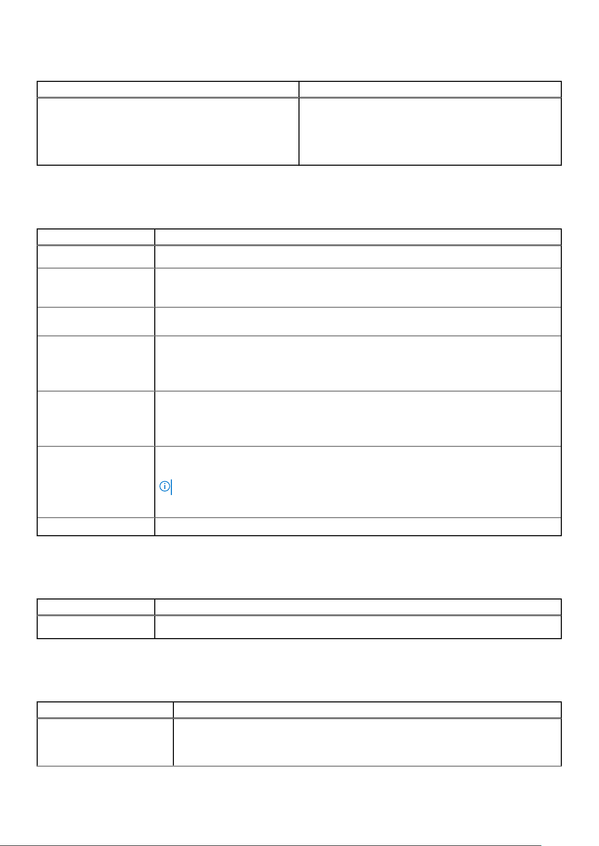
Table 29. Wireless
Option Description
The options are:
● WLAN/WiGig
● Bluetooth
All the options are enabled by default.
Maintenance
Table 30. Maintenance
Option Description
Service Tag
Asset Tag
SERR Messages Controls the SERR message mechanism. This option is set by default. Some graphics cards
BIOS Downgrade
Data Wipe
BIOS Recovery
First Power On Date Allows you the set Ownership date. The option Set Ownership Date is not set by default.
Displays the service tag of your computer.
Allows you to create a system asset tag if an asset tag is not already set.
This option is not set by default.
require that the SERR message mechanism be disabled.
Allows you to flash previous revisions of the system firmware.
● Allow BIOS Downgrade
This option is set by default.
Allows you to securely erase data from all internal storage devices.
● Wipe on Next Boot
This option is not set by default.
BIOS Recovery from Hard Drive—This option is set by default. Allows you to recover the
corrupted BIOS from a recovery file on the HDD or an external USB key.
NOTE: BIOS Recovery from Hard Drive field must be enabled.
Always Perform Integrity Check—Performs integrity check on every boot.
System logs
Table 31. System Logs
Option Description
BIOS events
Allows you to view and clear the System Setup (BIOS) POST events.
Advanced configuration
Table 32. Advanced configuration
Option Description
ASPM Allows you to set the ASPM level.
● Auto (default) - There is handshaking between the device and PCI Express hub to
determine the best ASPM mode supported by the device.
30 System setup
Page 31

Table 32. Advanced configuration (continued)
Option Description
● Disabled - ASPM power management is turned off at all time.
● L1 Only - ASPM power management is set to use L1.
PCIe Linkspeed Allows you to select the max PCIe link speed attainable by devices within the system.
● Auto (default)
● Gen1
● Gen2
SupportAssist System Resolution
Table 33. SupportAssist System Resolution
Option Description
Auto OS Recovery Threshold Allows you to control the automatic boot flow for
SupportAssist System. Options are:
● Off
● 1
● 2 (Enabled by default)
● 3
SupportAssist OS Recovery Allows you to recover the SupportAssist OS Recovery
(Enabled by default).
BIOSConnect BIOSConnect enable or disable cloud Service OS upon
absence of Local OS Recovery (Enabled by default).
Updating the BIOS in Windows
Prerequisites
It is recommended to update your BIOS (System Setup) when you replace the system board or if an update is available.
About this task
NOTE:
If BitLocker is enabled, it must be suspended prior to updating the system BIOS, and then re enabled after the BIOS
update is completed.
Steps
1. Restart the computer.
2. Go to Dell.com/support.
● Enter the Service Tag or Express Service Code and click Submit.
● Click Detect Product and follow the instructions on screen.
3. If you are unable to detect or find the Service Tag, click Choose from all products.
4. Choose the Products category from the list.
NOTE: Choose the appropriate category to reach the product page.
5. Select your computer model and the Product Support page of your computer appears.
6. Click Get drivers and click Drivers and Downloads.
The Drivers and Downloads section opens.
7. Click Find it myself.
8. Click BIOS to view the BIOS versions.
System setup
31
Page 32
9. Identify the latest BIOS file and click Download.
10. Select your preferred download method in the Please select your download method below window, click Download File.
The File Download window appears.
11. Click Save to save the file on your computer.
12. Click Run to install the updated BIOS settings on your computer.
Follow the instructions on the screen.
Updating BIOS on systems with BitLocker enabled
CAUTION: If BitLocker is not suspended before updating the BIOS, the next time you reboot the system it will
not recognize the BitLocker key. You will then be prompted to enter the recovery key to progress and the
system will ask for this on each reboot. If the recovery key is not known this can result in data loss or an
unnecessary operating system re-install. For more information on this subject, see Knowledge Article:
https://www.dell.com/support/article/sln153694
Updating your system BIOS using a USB flash drive
About this task
If the computer cannot load into Windows but there is still a need to update the BIOS, download the BIOS file using another
computer and save it to a bootable USB flash drive.
NOTE: You must use a bootable USB flash drive. For more information, see the knowledge base article SLN143196.
Steps
1. Download the BIOS update .exe file to another computer.
2. Copy the .exe file onto the bootable USB flash drive.
3. Insert the USB flash drive into the computer that requires the BIOS update.
4. Restart the computer and press F12 when the Dell logo appears to display the One Time Boot Menu.
5. Using arrow keys, select USB Storage Device and press Enter.
6. The computer restarts to a Diag C:\> prompt.
7. Run the file by typing the complete filename and press Enter.
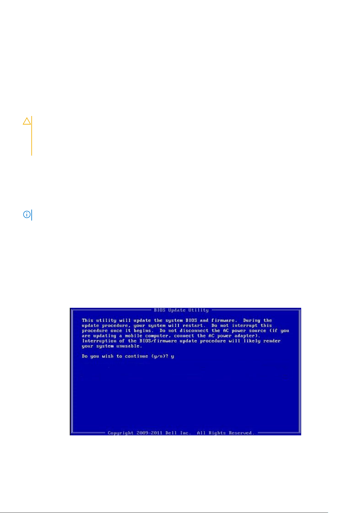
8. The BIOS Update Utility is displayed. Follow the on-screen instructions.
Figure 1. DOS BIOS Update Screen
32
System setup
Page 33

System and setup password
Table 34. System and setup password
Password type Description
System password Password that you must enter to log on to your system.
Setup password Password that you must enter to access and make changes to
the BIOS settings of your computer.
You can create a system password and a setup password to secure your computer.
CAUTION: The password features provide a basic level of security for the data on your computer.
CAUTION: Anyone can access the data stored on your computer if it is not locked and left unattended.
NOTE: System and setup password feature is disabled.
Assigning a system setup password
Prerequisites
You can assign a new System or Admin Password only when the status is in Not Set.
About this task
To enter the system setup, press F2 immediately after a power-on or reboot.
Steps
1. In the System BIOS or System Setup screen, select Security and press Enter.
The Security screen is displayed.
2. Select System/Admin Password and create a password in the Enter the new password field.
Use the following guidelines to assign the system password:
● A password can have up to 32 characters.
● The password can contain the numbers 0 through 9.
● Only lower case letters are valid, upper case letters are not allowed.
● Only the following special characters are allowed: space, (”), (+), (,), (-), (.), (/), (;), ([), (\), (]), (`).
3. Type the system password that you entered earlier in the Confirm new password field and click OK.
4. Press Esc and a message prompts you to save the changes.
5. Press Y to save the changes.
The computer reboots.
Deleting or changing an existing system setup password
Prerequisites
Ensure that the Password Status is Unlocked (in the System Setup) before attempting to delete or change the existing
System and Setup password. You cannot delete or change an existing System or Setup password, if the Password Status is
Locked.
About this task
To enter the System Setup, press F2 immediately after a power-on or reboot.
System setup
33
Page 34

Steps
1. In the System BIOS or System Setup screen, select System Security and press Enter.
The System Security screen is displayed.
2. In the System Security screen, verify that Password Status is Unlocked.
3. Select System Password, alter or delete the existing system password and press Enter or Tab.
4. Select Setup Password, alter or delete the existing setup password and press Enter or Tab.
NOTE: If you change the System and/or Setup password, re enter the new password when prompted. If you delete the
System and Setup password, confirm the deletion when prompted.
5. Press Esc and a message prompts you to save the changes.
6. Press Y to save the changes and exit from System Setup.
The computer restarts.
Clearing BIOS (System Setup) and System passwords
About this task
NOTE: To conduct a BIOS and System password reset, you must call the Dell Tech Support number in your region.
Steps
1. Key in your computer's service tag number into the locked BIOS/system setup screen.
2. Convey the code generated to the Dell Tech Support agent.
3. The Dell Tech Support agent will provide a 32 character Master System Password that can be used to access the locked
BIO/system setup.
34
System setup
Page 35

Software
This chapter details the supported operating systems along with instructions on how to install the drivers.
Downloading Windows drivers
Steps
1. Turn on the .
2. Go to Dell.com/support.
3. Click Product Support, enter the Service Tag of your , and then click Submit.
NOTE: If you do not have the Service Tag, use the auto detect feature or manually browse for your model.
4. Click Drivers and Downloads.
5. Select the operating system installed on your .
6. Scroll down the page and select the driver to install.
7. Click Download File to download the driver for your .
8. After the download is complete, navigate to the folder where you saved the driver file.
9. Double-click the driver file icon and follow the instructions on the screen.
5
Software 35
Page 36
Getting help and contacting Dell
Self-help resources
You can get information and help on Dell products and services using these self-help resources:
Table 35. Self-help resources
Self-help resources Resource location
Information about Dell products and services https://www.dell.com/
Dell Support
Tips
Contact Support In Windows search, type Contact Support, and press
Enter.
6
Online help for operating system
Troubleshooting information, user manuals, set up
instructions, product specifications, technical help blogs,
drivers, software updates, and so on.
Dell knowledge base articles for various of system concerns:
Learn and get more information about your product:
● Product specifications
● Operating system
● Setting up and using your product
● Data backup
● Troubleshooting and diagnostics
● Factory and system restore
● BIOS information
● Windows: https://www.dell.com/support/windows
● Linux: https://www.dell.com/support/linux
https://www.dell.com/support/home/
1. Go to https://www.dell.com/support/home/?
app=knowledgebase.
2. Type the subject or keyword in the Search box.
3. Click Search to retrieve the related articles.
Dell provides several online and telephone-based support and
service options. If you do not have an active Internet
connection, you can find contact information about your
purchase invoice, packing slip, bill, or Dell product catalog.
● Select Detect Product.
● Locate your product through the drop-down menu under
View Products.
● Enter the Service Tag number or Product ID in the
search bar.
● Once on product support page, scroll down to Manuals and
Documents section to preview all the Manuals, documents,
and other information for your product.
36 Getting help and contacting Dell
Page 37

Contacting Dell
Dell provides several online and telephone-based support and service options. If you do not have an active Internet connection,
you can find contact information about your purchase invoice, packing slip, bill, or Dell product catalog. Availability varies by
country/region and product, and some services may not be available in your area. To contact Dell for sales, technical support, or
customer service issues:
1. Go to https://www.dell.com/support/.
2. Select your country/region from the drop-down menu on the lower right corner of the page.
3. For customized support:
a. Enter your system Service Tag in the Enter your Service Tag field.
b. Click submit.
● The support page that lists the various support categories is displayed.
4. For general support:
a. Select your product category.
b. Select your product segment.
c. Select your product.
● The support page that lists the various support categories is displayed.
5. For contact details of Dell Global Technical Support, see https://www.dell.com/contactdell.
NOTE: The Contact Technical Support page is displayed with details to call, chat, or email the Dell Global Technical
Support team.
NOTE: Availability varies by country/region and product, and some services may not be available in your area.
Getting help and contacting Dell 37
 Loading...