

Page 1

Dell EMC VxRail G560 and G560F Appliance
Owner's Manual
Regulatory Model: E43S Series
Regulatory Type: E43S001
Page 2

Notes, cautions, and warnings
NOTE: A NOTE indicates important information that helps you make better use of your product.
CAUTION: A CAUTION indicates either potential damage to hardware or loss of data and tells you how to avoid the problem.
WARNING: A WARNING indicates a potential for property damage, personal injury, or death.
Copyright © 2018 Dell Inc. or its subsidiaries. All rights reserved. Dell, EMC, and other trademarks are trademarks of Dell Inc. or its subsidiaries. Other
trademarks may be trademarks of their respective owners.
2018 - 07
Rev. A00
Page 3

Contents
1 Overview........................................................................................................................................................5
Supported congurations..................................................................................................................................................5
Front view of the appliance...............................................................................................................................................7
Front view of the control panels................................................................................................................................ 8
Back view of the appliance...............................................................................................................................................9
Diagnostic indicators.........................................................................................................................................................11
Drive indicator codes...................................................................................................................................................11
Power supply unit indicator codes.............................................................................................................................11
Locating serial number of your appliance...................................................................................................................... 12
Looking up your appliance serial number in VxRail Manager.................................................................................13
Locating your physical VxRail Service Tag number and PSNT ............................................................................ 13
2 Technical specications................................................................................................................................14
Dimensions of the VxRail G Series appliance................................................................................................................15
Chassis weight..................................................................................................................................................................16
Processor specications..................................................................................................................................................16
PSU specications............................................................................................................................................................16
System battery..................................................................................................................................................................17
Expansion bus specications...........................................................................................................................................17
Memory specications..................................................................................................................................................... 17
Hard drives and storage specications.......................................................................................................................... 17
Video specications..........................................................................................................................................................18
Environmental specications...........................................................................................................................................18
Temperature specications........................................................................................................................................18
Relative humidity specications................................................................................................................................19
Maximum vibration specications............................................................................................................................ 19
Maximum shock specications................................................................................................................................. 19
Maximum altitude specications...............................................................................................................................19
Operating temperature de-rating specications.................................................................................................... 20
Particulate and gaseous contamination specications..........................................................................................20
Standard operating temperature specications......................................................................................................21
Expanded operating temperature specications ...................................................................................................24
3 Documentation resources............................................................................................................................ 25
4 Initial setup and conguration......................................................................................................................26
5 Pre-operating system management applications..........................................................................................27
Options to manage the pre-operating system applications........................................................................................27
iDRAC conguration.........................................................................................................................................................27
Log in to iDRAC.......................................................................................................................................................... 27
Contents
3
Page 4

6 Replacing and adding hardware................................................................................................................... 29
Using the SolVe Desktop application for VxRail Series hardware tasks....................................................................29
Supported hardware components................................................................................................................................. 29
System memory...............................................................................................................................................................30
General memory module installation guidelines......................................................................................................30
Expansion cards................................................................................................................................................................31
PCIe slot priority ........................................................................................................................................................ 31
7 Getting help.................................................................................................................................................33
Contacting Dell EMC.......................................................................................................................................................33
Registering for online support........................................................................................................................................33
Accessing support resources..........................................................................................................................................33
4 Contents
Page 5

Overview
The VxRail G Series appliance is an ultra-dense 2U enclosure that can support up to four independent one-socket (1S) or two-socket (2S)
sleds. Each sled supports up to two Intel Xeon Scalable product family processors up to 28 cores per processor. The sled also supports 16
memory modules, dedicated mezzanine, PCIe and Open Compute Project (OCP) adapters for expansion and connectivity. The appliance
supports up to 24 x 2.5 inch SAS or SATA drives including up to 4 NVMe SSDs.
Topics:
• Supported congurations
• Front view of the appliance
• Back view of the appliance
• Diagnostic indicators
• Locating serial number of your appliance
Supported congurations
The VxRail G Series appliance supports the following congurations:
1
Overview 5
Page 6
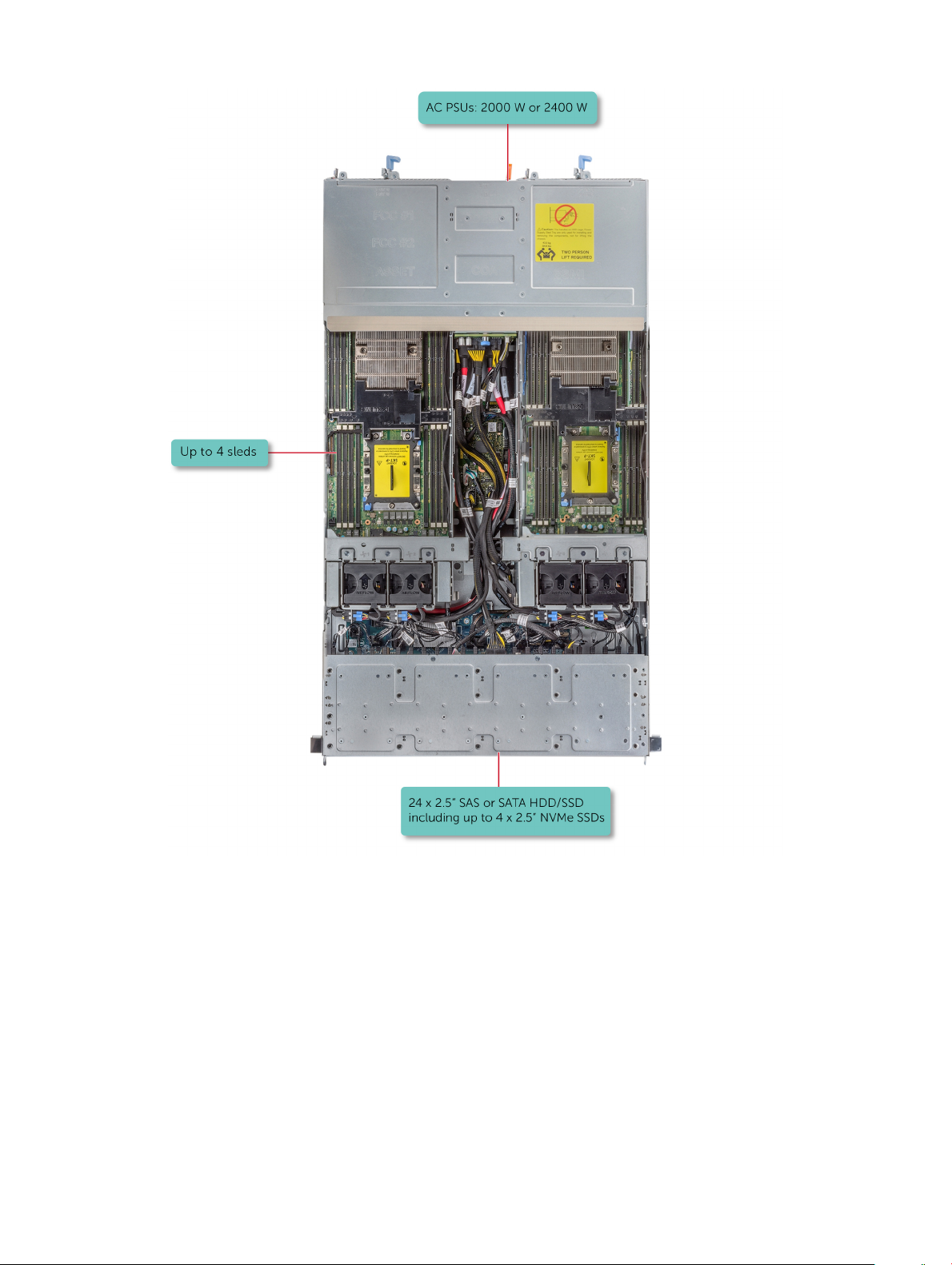
Figure 1. Supported congurations for enclosure
6
Overview
Page 7
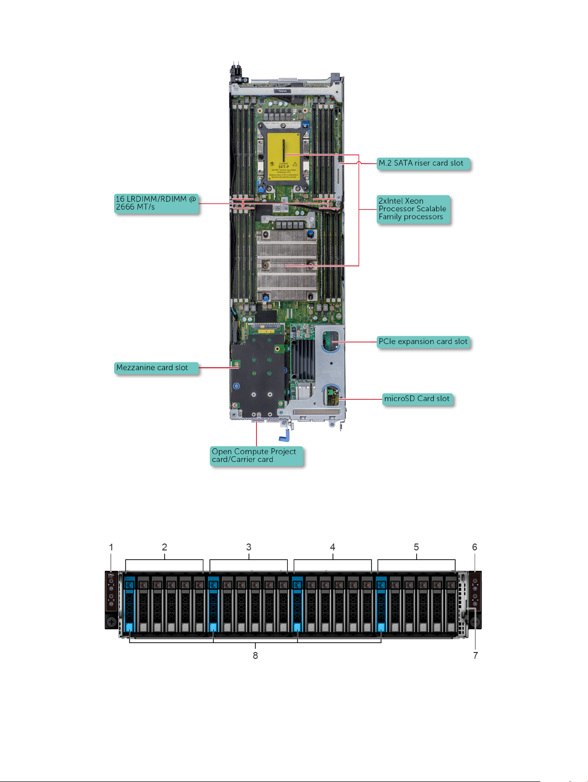
Figure 2. Supported congurations for sled
Front view of the appliance
Figure 3. Front view of the enclosure with 24 x 2.5 inch drives
left control panel 2 drives 0–5 mapped to sled 1
1
Overview 7
Page 8
3 drives 6-11 mapped to sled 2 4 drives 12-17 mapped to sled 3
5 drives 18-23 mapped to sled 5 6 right control panel
7 EST tag 8 (optional) NVMe hard drive location
Front view of the control panels
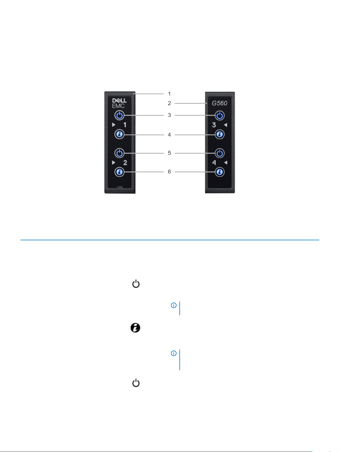
Figure 4. Front view of the left and right control panels
Table 1. Control panel
Item Indicator or button Icon Description
1 left control panel - The power-on indicator and system identication LED for sleds 1 and
2 are located on the left control panel.
2 right control panel - The power-on indicator and system identication LED for sleds 3 and
4 are located on the right control panel.
3 power-on indicator or system
state indicator or power button
for sleds 1 and 3
4 system identication button for
sleds 1 and 3
Press the power button to turn the sled on or o.
The power-on indicator turns amber when a critical system event
occurs.
NOTE: To gracefully shut down an ACPI-compliant
operating system, press the power button.
Press the system ID button:
• To locate a particular sled within the enclosure.
• To turn the system ID on or o.
NOTE: If the sled stops responding during POST, press and
hold the system ID button (for more than ve seconds) to
enter the BIOS progress mode.
5 power-on indicator or system
state indicator or power button
for sleds 2 and 4
8 Overview
Press the power button to turn the sled on or o.
The power-on indicator turns amber when a critical system event
occurs.
Page 9
Item Indicator or button Icon Description
NOTE: To gracefully shut down an ACPI-compliant
operating system, press the power button.
6 system identication button for
sleds 2 and 4
Back view of the appliance
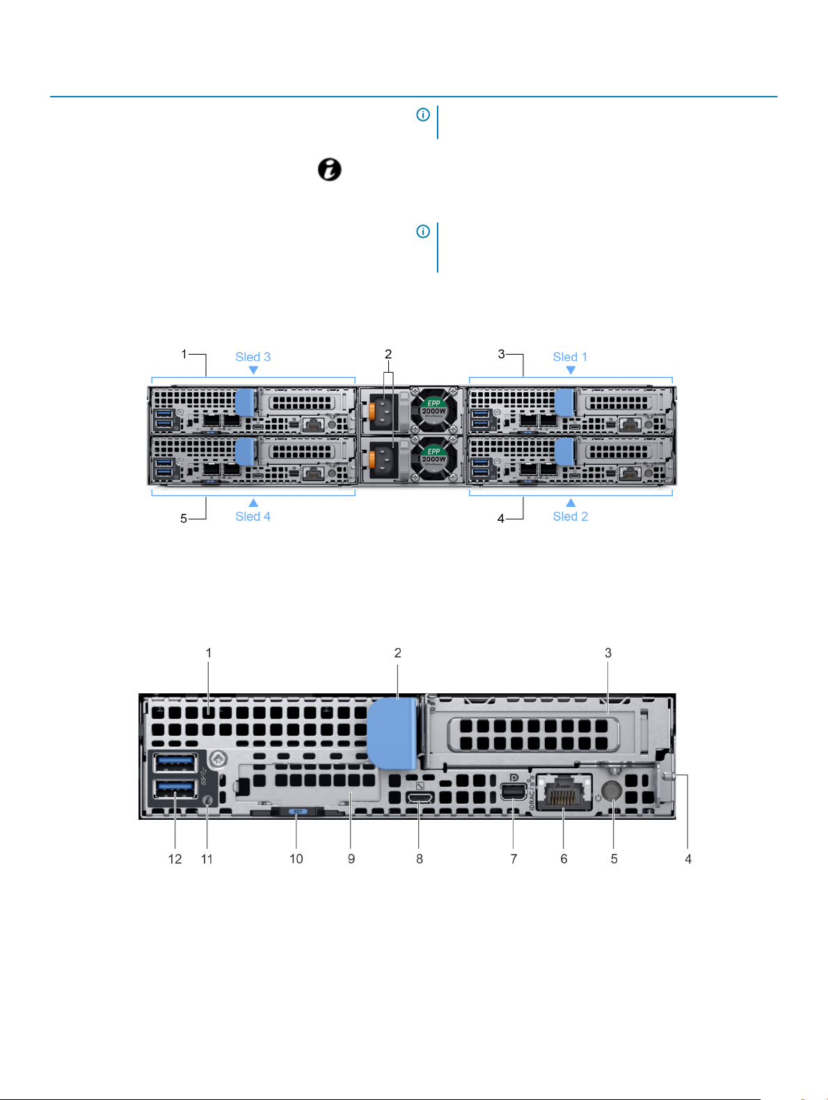
Figure 5. Back view of the enclosure with sleds
Press the system ID button:
• To locate a particular sled within the enclosure.
• To turn the system ID on or o.
NOTE: If the sled stops responding during POST, press and
hold the system ID button (for more than ve seconds) to
enter the BIOS progress mode.
1
sled 3 2 power supply unit (2)
3 sled 1 4 sled 2
5 sled 4
Figure 6. Back view of the sled
Overview
9
Page 10

Table 2. Back panel features
Item Indicator, button, or connector Icon Description
1 mezzanine card slot N/A
Enables you to connect mezzanine expansion cards.
For more information, see Technical specications.
2 sled release handle N/A
3 Low Prole PCIe card slot N/A
4 sled release lock N/A
5 rear power button N/A
6 iDRAC or NIC port Enables you to remotely access iDRAC.
7 mini display port Enables you to connect a display device to the
8 iDRAC Direct micro USB port
9 OCP card slot N/A
10 EST pull out tab N/A This tab has the unique Express Service Code,
11 system id indicator The System Identication (ID) LED is available on the
Enables you to remove the sled from the enclosure.
Enables you to connect PCI Express expansion cards.
For more information, see Technical specications.
Enables you to remove the sled from the enclosure.
Enables you to power on the sled while accessing it
from the rear.
system. For more information, see Technical
specications.
Enables you to connect a portable device to the sled.
Enables you to connect Open Compute Project
(OCP) expansion cards. For more information, see
Technical specications.
Service Tag, and MAC address labels.
back of the system. Press the system ID button on
the front of the enclosure to identify a system in a
rack.
12 USB 3.0 port (2) The USB ports are 9-pin and 3.0-compliant. These
ports enable you to connect USB devices to the
system.
10 Overview
Page 11

Diagnostic indicators
The diagnostic indicators on the appliance indicate operation and error status.
Drive indicator codes
Each drive carrier has an activity LED indicator and a status LED indicator. The indicators provide information about the current status of
the drive. The activity LED indicator indicates whether the drive is currently in use or not. The status LED indicator indicates the power
condition of the drive.
Figure 7. Drive indicators
1
Drive activity LED indicator 2 Drive status LED indicator
3 Drive capacity label
NOTE: This appliance uses a passive backplane and the status LED indicator does not turn on.
NOTE: Drive status indicator behavior is managed by VxRail. Not all drive status indicators may be used.
Power supply unit indicator codes
AC power supply units (PSUs) have an illuminated translucent handle that serves as an indicator. The indicator shows whether power is
present or if a power fault has occurred.
: The 2400 W and 2000 W PSUs use a C19 or C20 connector.
NOTE
Overview 11
Page 12

Figure 8. AC PSU status indicator
1 AC PSU status indicator/handle
Table 3. AC PSU status indicator codes
Power indicator codes Condition
Green A valid power source is connected to the PSU and the PSU is operational.
Blinking amber Indicates a problem with the PSU.
Not illuminated Power is not connected to the PSU.
Blinking green When the rmware of the PSU is being updated, the PSU handle blinks green.
CAUTION: Do not disconnect the power cable or unplug the PSU when updating rmware. If
rmware update is interrupted, the PSUs do not function.
Blinking green and turns o When hot-plugging a PSU, the PSU handle blinks green ve times at a rate of 4 Hz and turns o. This
indicates a PSU mismatch with respect to eciency, feature set, health status, or supported voltage.
CAUTION: The PSUs must have the same type of label; for example, Extended Power
Performance (EPP) label. Mixing PSUs from previous generations of VxRail servers is not
supported, even if the PSUs have the same power rating. This results in a PSU mismatch
condition or failure to turn the system on.
CAUTION: When correcting a PSU mismatch, replace only the PSU with the blinking indicator.
Swapping the PSU to make a matched pair can result in an error condition and unexpected
system shutdown. To change from a high output conguration to a low output conguration or
vice versa, you must turn o the system.
CAUTION: If two PSUs are used, they must be of the same type and have the same maximum
output power.
Locating serial number of your appliance
To get support for your appliance, use the VxRail Appliance serial number, also called the Product Serial Number Tag (PSNT). The PSNT is
a 14-digit number used to identify your appliance to Dell EMC support.
: Only use the VxRail Appliance serial number to contact Customer Support. Sometimes, you may need to supply the 7-
NOTE
digit Service Tag number.
There are two identication tags on your appliance:
• The VxRail appliance serial number—You can nd the serial number in VxRail Manager, or printed on the information tag.
• The Service Tag — You can nd the Service Tag printed on the physical appliance.
Overview
12
Page 13

Looking up your appliance serial number in VxRail Manager
1 In VxRail Manager, on the left navigation bar, click Health.
2 To display appliance information, click Physical.
3 Observe the VxRail Appliance serial number, listed under the appliance ID as the PSNT.
Locating your physical VxRail Service Tag number and PSNT
Your hardware is identied by a unique Service Tag number and Product Serial Number Tag (PSNT) . The Service Tag and PSNT is found
on the front of the appliance by pulling out the information tag.
Alternatively, the information may be on a sticker on the chassis of the appliance. This information is used by Dell EMC to route support
calls to the appropriate personnel.
NOTE: Use the 7-digit Service Tag, only if instructed by Technical Support.
Figure 9. VxRail Service Tag
1
Service Tag number 2 PSNT
Overview 13
Page 14

Technical specications
The technical and environmental specications of your appliance are outlined in this section.
Topics:
• Dimensions of the VxRail G Series appliance
• Chassis weight
• Processor specications
• PSU specications
• System battery
• Expansion bus specications
• Memory specications
• Hard drives and storage specications
• Video specications
• Environmental specications
2
14 Technical specications
Page 15

Dimensions of the VxRail G Series appliance
Figure 10. Dimensions of the enclosure
Table 4. Dimensions of the enclosure
Xa Xb Y Za Zb Zc
482.6 mm (19 inches) 448 mm (17.63
inches)
86.8 mm (3.41
inches)
26.8 mm (1.05
inches)
763.2 mm (30.28
inches)
797.3 mm (31.38
inches)
Technical specications 15
Page 16

Figure 11. Dimensions of the sled
Table 5. Dimensions of the sled
X Y Z
17.44 mm (6.86 inches) 4.05 mm (1.59 inches) 57.45 mm (22.61 inches)
Chassis weight
Table 6. Chassis weight of the
System Maximum weight (with all sleds and drives)
24 x 2.5-inch hard drive systems 41.46 Kg (91.40 lb)
VxRail G Series appliance
Processor specications
The VxRail G Series appliance supports up to two Intel Xeon Scalable product family processors in each of the four independent sleds. Each
processor supports up to 28 cores.
PSU specications
The VxRail G Series appliance supports two AC power supply units (PSUs).
Table 7. PSU
PSU wattage Class Heat dissipation
2400 W AC
2000 W AC
specications
Platinum
Platinum
(maximum)
Frequency Voltage Maximum input current
715 BTU/hr 50/60 Hz
635 BTU/hr 50/60 Hz
100–240 V AC,
autoranging
100–240 V AC,
autoranging
14 A–16 A
11.5 A
16 Technical specications
Page 17

NOTE: Heat dissipation is calculated using the PSU wattage rating.
NOTE: This system is also designed to connect to the IT power systems with a phase to phase voltage not exceeding 240 V.
NOTE: If a system with 2400 W AC PSU operates at low line 100–120 V AC, then the power rating per PSU is derated to 1400 W.
NOTE: If a system with 2000 W AC PSU operates at low line 100–120 V AC, then the power rating per PSU is derated to 1000 W.
System battery
The VxRail G Series appliance uses a CR 2032 3V replaceable lithium coin cell battery.
Expansion bus specications
The VxRail G Series appliance supports four Generation 3 capable PCIe slots.
Table 8. Expansion bus specications
PCIe Slots Description Form factor
x8 Mezz PCIe riser Slot 1: x8 PCIe Gen3 from CPU 1 Custom form factor
x8+x8 OCP Mezz riser
x16 PCIe main riser Slot 4: x16 PCIe Gen3 CPU 1 Standard Low Prole PCIe form factor
x16 buried PCIe riser Slot 5: x16 PCIe Gen3 from CPU 2 Custom form factor
Slot 3: x8 PCIe Gen3 from CPU 1 Standard Open Compute Project (OCP)
form factor
NOTE: M.2 SATA riser is supported
on the buried riser.
Memory specications
The VxRail G Series appliance supports DDR4 registered DIMMs (RDIMMs) and Load Reduced DIMMS (LRDIMMs).
Table 9. Memory
Memory module sockets Architecture Memory capacity and
Sixteen 288-pin 2666 MT/s DDR4
specications
RDIMMs and LRDIMMS
with support for
advanced ECC or
memory optimized
operation
ranking
• Dual rank - 16 GB
• Dual rank - 32 GB
• Dual rank - 64 GB
• Octa rank - 128GB
Minimum RAM Maximum RAM
• 64 GB with a single
processor
• 128 GB with dual
processor
• 1024 GB with a single
processor
• 2048 GB with dual
processor
Hard drives and storage specications
The VxRail G Series appliance supports SAS and SATA hard drives and Solid State Drives (SSDs).
Table 10. Supported drives for
Maximum number of drives in the enclosure Maximum number of drives assigned per sled
24 x 2.5-inch drive systems with NVMe The NVMe backplane supports either of these congurations:
appliance
Technical specications 17
Page 18

Maximum number of drives in the enclosure Maximum number of drives assigned per sled
• One NVMe drive and ve SAS or SATA hard drives and SSDs per sled
• Six SAS or SATA hard drives and SSDs per sled
M.2 SATA drive The supported capacity of the M.2 SATA card is 240 GB
NOTE: The M.2 SATA card can be installed on the x16 riser slot (slot
5).
microSD card (64 GB) One on each PCIe riser of each sled
Video specications
The VxRail G Series appliance supports a Matrox G200 integrated graphics card with 16 MB RAM.
Table 11. Supported video resolution options
Resolution Refresh rate (Hz) Color depth (bits)
1024 x 768 60 up to 24
1280 x 800 60 up to 24
1280 x 1024 60 up to 24
1360 x 768 60 up to 24
1440 x 900 60 up to 24
Environmental specications
The sections below contains information about the environmental specications of the system.
Temperature specications
Table 12. Temperature
Temperature Specications
Storage –40°C to 65°C (–40°F to 149°F)
Continuous operation (for altitude less than 950 m or 3117 ft) 10°C to 35°C (50°F to 95°F) with no direct sunlight on the
Fresh air For information about fresh air, see Expanded operating
Maximum temperature gradient (operating and storage) 20°C/h (36°F/h)
NOTE: Some congurations require a lower ambient temperature for more information, see Standard operating temperature
specications.
specications
equipment.
temperature.
18 Technical specications
Page 19

Relative humidity specications
Table 13. Relative humidity specications
Relative humidity Specications
Storage 5% to 95% RH with 33°C (91°F) maximum dew point. Atmosphere
must be non-condensing at all times.
Operating 10% to 80% relative humidity with 29°C (84.2°F)
Maximum vibration specications
Table 14. Maximum vibration specications
Maximum vibration Specications
Operating 0.26 Grms at 5 Hz to 350 Hz (all operation orientations).
Storage 1.88 Grms at 10 Hz to 500 Hz for 15 min (all six sides tested).
Maximum shock specications
Table 15. Maximum shock
Maximum shock Specications
Operating 24 executed shock pulses 6 G in the positive and negative x, y, z
Storage Six consecutively executed shock pulses of 71 G in the positive and
specications
axis for up to 11 ms (four pulses on each side of the system).
negative x, y, z axes for up to 2 ms (one pulse on each side of the
system).
Maximum altitude specications
Table 16. Maximum altitude
Maximum altitude Specications
Operating 3048 m (10,000 ft)
Storage 12,000 m (39,370 ft)
specications
Technical specications 19
Page 20

Operating temperature de-rating specications
Table 17. Operating temperature
Operating temperature de-rating Specications
Up to 35°C (95°F) Maximum temperature is reduced by 1°C/300 m (1°F/547 ft)
above 950 m (3,117 ft).
35°C to 40°C (95°F to 104°F) Maximum temperature is reduced by 1°C/175 m (1°F/319 ft) above
950 m (3,117 ft).
40°C to 45°C (104°F to 113°F) Maximum temperature is reduced by 1°C/125 m (1°F/228
Particulate and gaseous contamination specications
Table 18. Particulate contamination specications
Particulate contamination Specications
Air ltration Data center air ltration as dened by ISO
Class 8 per ISO 14644-1 with a 95% upper
condence limit.
NOTE: This condition applies only to data center environments. Air ltration requirements do not apply to IT equipment
designed to be used outside a data center, in environments such as an oce or factory oor.
NOTE: Air entering the data center must have MERV11 or MERV13 ltration.
Conductive dust Air must be free of conductive dust, zinc
whiskers, or other conductive particles.
NOTE: This condition applies to data center and non-data center environments.
Corrosive dust Air must be free of corrosive dust.
Residual dust present in the air must have a deliquescent point less than 60% relative humidity.
NOTE: This condition applies to data center and non-data center environments.
Table 19. Gaseous contamination specications
Gaseous contamination Specications
Copper coupon corrosion rate <300 Å/month per Class G1 as dened by ANSI/ISA71.04-1985.
Silver coupon corrosion rate <200 Å/month as dened by AHSRAE TC9.9.
NOTE: Maximum corrosive contaminant levels measured at ≤50% relative humidity.
20 Technical specications
Page 21

Standard operating temperature specications
NOTE: All components including the DIMMs, communication cards, M.2 SATA, and PERC cards can be supported with sucient
thermal margin if the ambient temperature is equal to or below to the maximum continuous operating temperature listed in these
tables with the exception of the Mellanox DP LP card.
Table 20. Standard operating temperature specications
Standard operating temperature Specications
Temperature ranges (for altitude less than 950 m or 3117 ft) 10°C to 35°C (50°F to 95°F) with no direct sunlight on the
equipment.
NOTE: Some congurations require a lower ambient temperature. For more information see the following tables.
NOTE: Not supported: Indicates that the conguration is not thermally supported.
Table 21. Maximum continuous operating temperature for dual processor conguration
TDP (W)
205 W
200 W
165 W
155 W
150 W
Processor model
number
8180 CPU1: FMM2M | CPU2: V2DRD
8180M CPU1: FMM2M | CPU2: V2DRD
8168 CPU1: FMM2M | CPU2: V2DRD
6154 CPU1: FMM2M | CPU2: V2DRD
6150 CPU1: JYKMM | CPU2: V2DRD
6146 CPU1: JYKMM | CPU2: V2DRD
8176 CPU1: JYKMM | CPU2: V2DRD
8176M CPU1: JYKMM | CPU2: V2DRD
8170M CPU1: JYKMM | CPU2: V2DRD
8170 CPU1: JYKMM | CPU2: V2DRD
6144 CPU1: FMM2M | CPU2: V2DRD
6148 CPU1: JYKMM | CPU2: V2DRD
Supported heat sinks
Max DIMM count per
CPU
CPU1: 6 | CPU2: 8
CPU1: 6 | CPU2: 8
CPU1: 6 | CPU2: 8
CPU1: 6 | CPU2: 8
CPU1: 8 | CPU2: 8
CPU1: 6 | CPU2: 8
CPU1: 8 | CPU2: 8
CPU1: 8 | CPU2: 8
CPU1: 8 | CPU2: 8
CPU1: 8 | CPU2: 8
CPU1: 6 | CPU2: 8
CPU1: 8 | CPU2: 8 30°C/86°F
24x 2.5” HDDs enclosure
Not supported
Not supported
Not supported
6142 CPU1: FMM2M | CPU2: V2DRD
6136 CPU1: JYKMM | CPU2: V2DRD
8164 CPU1: JYKMM | CPU2: V2DRD
8160M CPU1: JYKMM | CPU2: V2DRD
CPU1: 8 | CPU2: 8 30°C/86°F
CPU1: 8 | CPU2: 8 30°C/86°F
CPU1: 8 | CPU2: 8 30°C/86°F
CPU1: 8 | CPU2: 8 30°C/86°F
Technical specications 21
Page 22

TDP (W)
Processor model
number
8160 CPU1: JYKMM | CPU2: V2DRD
Supported heat sinks
Max DIMM count per
CPU
CPU1: 8 | CPU2: 8 30°C/86°F
24x 2.5” HDDs enclosure
140 W
130 W
125 W
115 W
105 W
6132 CPU1: JYKMM | CPU2: V2DRD
6152 CPU1: JYKMM | CPU2: V2DRD
6140M CPU1: JYKMM | CPU2: V2DRD
6140 CPU1: JYKMM | CPU2: V2DRD
6134 CPU1: JYKMM | CPU2: V2DRD
6126 CPU1: JYKMM | CPU2: V2DRD
8153 CPU1: JYKMM | CPU2: V2DRD
6138 CPU1: JYKMM | CPU2: V2DRD
6130 CPU1: JYKMM | CPU2: V2DRD
6128 CPU1: FMM2M | CPU2: V2DRD
5122 CPU1: FMM2M | CPU2: V2DRD
5120 CPU1: JYKMM | CPU2: V2DRD
5118 CPU1: JYKMM | CPU2: V2DRD
CPU1: 8 | CPU2: 8 30°C/86°F
CPU1: 8 | CPU2: 8 30°C/86°F
CPU1: 8 | CPU2: 8 30°C/86°F
CPU1: 8 | CPU2: 8 30°C/86°F
CPU1: 8 | CPU2: 8 30°C/86°F
CPU1: 8 | CPU2: 8 30°C/86°F
CPU1: 8 | CPU2: 8 30°C/86°F
CPU1: 8 | CPU2: 8 30°C/86°F
CPU1: 8 | CPU2: 8 30°C/86°F
CPU1: 6 | CPU2: 8 30°C/86°F
CPU1: 6 | CPU2: 8 35°C/95°F
CPU1: 8 | CPU2: 8 35°C/95°F
CPU1: 8 | CPU2: 8 35°C/95°F
85 W
Table 22. Maximum continuous operating temperature for single processor conguration
TDP (W)
205 W
5115 CPU1: JYKMM | CPU2: V2DRD
4116 CPU1: JYKMM | CPU2: V2DRD
4114 CPU1: JYKMM | CPU2: V2DRD
4112 CPU1: JYKMM | CPU2: V2DRD
4110 CPU1: JYKMM | CPU2: V2DRD
4108 CPU1: JYKMM | CPU2: V2DRD
3106 CPU1: JYKMM | CPU2: V2DRD
3104 CPU1: JYKMM | CPU2: V2DRD
Processor model
number
8180 CPU1: FMM2M
8180M CPU1: FMM2M
Supported heat sinks Max DIMM count per CPU 24x 2.5” HDDs enclosure
CPU1: 8 | CPU2: 8 35°C/95°F
CPU1: 8 | CPU2: 8 35°C/95°F
CPU1: 8 | CPU2: 8 35°C/95°F
CPU1: 8 | CPU2: 8 35°C/95°F
CPU1: 8 | CPU2: 8 35°C/95°F
CPU1: 8 | CPU2: 8 35°C/95°F
CPU1: 8 | CPU2: 8 35°C/95°F
CPU1: 8 | CPU2: 8 35°C/95°F
CPU1: 6
CPU1: 6
35°C/95°F
35°C/95°F
22 Technical specications
Page 23

TDP (W)
Processor model
number
8168 CPU1: FMM2M
Supported heat sinks Max DIMM count per CPU 24x 2.5” HDDs enclosure
CPU1: 6
35°C/95°F
200 W
165 W
155 W
150 W
6154 CPU1: FMM2M
6150 CPU1: FMM2M
6146 CPU1: FMM2M
8176 CPU1: FMM2M
8176M CPU1: FMM2M
8170M CPU1: FMM2M
8170 CPU1: FMM2M
6144 CPU1: FMM2M
6148 CPU1: FMM2M
6142 CPU1: FMM2M
6136 CPU1: FMM2M
8164 CPU1: FMM2M
8160M CPU1: FMM2M
CPU1: 6
CPU1: 8
CPU1: 6
CPU1: 8
CPU1: 8
CPU1: 8
CPU1: 8
CPU1: 6
CPU1: 8
CPU1: 8
CPU1: 8
CPU1: 8
CPU1: 8
35°C/95°F
35°C/95°F
35°C/95°F
35°C/95°F
35°C/95°F
35°C/95°F
35°C/95°F
35°C/95°F
35°C/95°F
35°C/95°F
35°C/95°F
35°C/95°F
35°C/95°F
140 W
130 W
125 W
115 W
105 W
8160 CPU1: FMM2M
6132 CPU1: FMM2M
6152 CPU1: FMM2M
6140M CPU1: FMM2M
6140 CPU1: FMM2M
6134 CPU1: FMM2M
6126 CPU1: FMM2M
8153 CPU1: FMM2M
6138 CPU1: FMM2M
6130 CPU1: FMM2M
6128 CPU1: FMM2M
5122 CPU1: FMM2M
5120 CPU1: FMM2M
CPU1: 8
CPU1: 8
CPU1: 8
CPU1: 8
CPU1: 8
CPU1: 8
CPU1: 8
CPU1: 8
CPU1: 8
CPU1: 8
CPU1: 6
CPU1: 6
CPU1: 8
35°C/95°F
35°C/95°F
35°C/95°F
35°C/95°F
35°C/95°F
35°C/95°F
35°C/95°F
35°C/95°F
35°C/95°F
35°C/95°F
35°C/95°F
35°C/95°F
35°C/95°F
Technical specications 23
Page 24

TDP (W)
Processor model
number
5118 CPU1: FMM2M
Supported heat sinks Max DIMM count per CPU 24x 2.5” HDDs enclosure
CPU1: 8
35°C/95°F
85 W
70 W
5115 CPU1: FMM2M
4116 CPU1: FMM2M
4114 CPU1: FMM2M
4112 CPU1: FMM2M
4110 CPU1: FMM2M
4108 CPU1: FMM2M
3106 CPU1: FMM2M
3104 CPU1: FMM2M
4109T CPU1: FMM2M
CPU1: 8
CPU1: 8
CPU1: 8
CPU1: 8
CPU1: 8
CPU1: 8
CPU1: 8
CPU1: 8
CPU1: 8
Expanded operating temperature specications
Table 23. Expanded operating temperature
Expanded operating temperature Specications
35°C/95°F
35°C/95°F
35°C/95°F
35°C/95°F
35°C/95°F
35°C/95°F
35°C/95°F
35°C/95°F
35°C/95°F
Continuous operation 5°C to 40°C at 5% to 85% RH with 29°C dew point.
NOTE: Outside the standard operating temperature (10°C to 35°C), the system
can operate continuously in temperatures as low as 5°C and as high as 40°C.
For temperatures between 35°C and 40°C, de-rate maximum allowable temperature by 1°C
per 175 m above 950 m (1°F per 319 ft).
≤ 1% of annual operating hours –5°C to 45°C at 5% to 90% RH with 29°C dew point.
NOTE: Outside the standard operating temperature (10°C to 35°C), the system
can operate down to –5°C or up to 45°C for a maximum of 1% of its annual
operating hours.
For temperatures between 40°C and 45°C, de-rate maximum allowable temperature by 1°C
per 125 m above 950 m (1°F per 228 ft).
NOTE: When operating in the expanded temperature range, system performance may be impacted.
NOTE: When operating in the expanded temperature range, ambient temperature warnings may be reported in the System Event
Log.
24 Technical specications
Page 25

Documentation resources
The documentation resources provides information on documents that you can refer while setting up and managing your appliance.
Table 24. Documentation resources
Document Provides information about... Location
Software Documents
3
Online help in the VxRail
Manager UI
Administrator Guide admin tasks and conceptual information. emc.com/vxrailsupport
Release Notes the product and any critical information about the release. emc.com/vxrailsupport
Hardware Documents
Getting started with your
appliance
Owner's Manual hardware details for your appliance along with technical
Service Procedure Documents
SolVe Desktop application the SolVe Desktop application. The SolVe Desktop application
all admin tasks, licensing, and product architecture
information.
setting up your appliance. emc.com/vxrailsupport
specications.
gathers critical information from EMC product guides and
combines it with expert Dell EMC support advice to generate
a procedure document that is concise and task driven.
VxRail Manager Online Help
emc.com/vxrailsupport
EMC Online Support site
NOTE: Download the SolVe Desktop
application, all generators are
available within the Solve Desktop.
Documentation resources 25
Page 26

Initial setup and conguration
For assistance on installation and deployment, contact your Dell EMC account team or your reseller for installation services.
WARNING: During the VxRail deployment process, an iDRAC account named vxadmin or PTAdmin is created. This account
provides hardware information the VxRail Manager and is required for VxRail Manager and cluster to function properly. Ensure
that you do not modify or delete this account.
NOTE: Do not install the appliance into a rack, or turn on the appliance without the initial conguration of your appliance.
4
26 Initial setup and conguration
Page 27

Pre-operating system management applications
You can manage basic settings and features of an appliance without booting to the operating system by using the appliance rmware.
NOTE:
• This appliance requires installation and deployment services. Do not rack the appliance, or turn on the appliance without the initial
congurations on your appliance. Contact your Dell EMC account team or your reseller for setting up your appliance.
• Dell EMC has optimized your appliance. It is not recommended to change any of these settings.
Topics:
• Options to manage the pre-operating system applications
• iDRAC conguration
Options to manage the pre-operating system applications
5
Your appliance has the following options to manage the pre-operating system applications:
• System Setup
• Boot Manager
• Dell Lifecycle Controller
• Preboot Execution Environment (PXE)
NOTE
: Dell EMC has optimized your appliance and it is not recommended to change any of these settings.
iDRAC conguration
The Integrated Dell Remote Access Controller (iDRAC) is designed to make appliance administrators more productive and improve the
overall availability of Dell EMC appliances. iDRAC alerts administrators to appliance issues, helps them perform remote appliance
management, and reduces the need for physical access to the appliance.
Log in to iDRAC
You can log in to iDRAC as:
• iDRAC user
• Microsoft Active Directory user
• Lightweight Directory Access Protocol (LDAP) user
If you have opted for secure default access to iDRAC, the iDRAC secure default password is available on the back of the appliance
Information tag. If you have not opted for secure default access to iDRAC, then the default user name and password are root and
calvin. You can also log in by using Single Sign-On or Smart Card.
Pre-operating system management applications 27
Page 28

NOTE: You must have iDRAC credentials to log in to iDRAC.
NOTE: Ensure that you change the default user name and password after setting up the iDRAC IP address.
The iDRAC IP address is pre-congured for DHCP. This can be changed to a static IP address by logging into iDRAC.
NOTE:
• To access iDRAC, connect the network cable to the Ethernet connector 1 on the system board.
• Ensure that you change the default user name and password after setting up the iDRAC IP address.
28 Pre-operating system management applications
Page 29

6
Replacing and adding hardware
Adding or replacing hardware component procedures on your VxRail appliance, such as hard disk drives (HDDs), solid state drives (SSDs),
and power supply units must be performed only by Dell EMC certied service technicians. For certain hardware components, you may need
to contact Customer Support for repair or replacement.
Using the SolVe Desktop application for VxRail Series hardware tasks
Step-by-step hardware component tasks such as replacement and upgrade procedures are available through the SolVe Desktop
application.
You must have an online support account to use the SolVe Desktop application.
NOTE: You can access SolVe Online at https://solveonline.emc.com.
WARNING: The VxRail Series procedures in the SolVe Desktop application for replacing hardware or any upgrade procedures
must be performed only by Dell EMC certied service technicians.
CAUTION: To avoid data loss, ensure that you refer to the VxRail Series procedures in the SolVe Desktop application before
replacing hardware or performing any upgrade procedures.
1 Log in to the EMC Online Support site.
2 Click SolVe on the main page.
3 Click the download link for the SolVe Desktop application.
4 Save the executable le and then run it to install the SolVe Desktop.
NOTE
: You can access support resources for your VxRail Series at https://solve.emc.com.
Supported hardware components
NOTE
: The list of FRU and CRU components is not exhaustive.
Table 25. Supported hardware components
Hardware Components Customer Replaceable Unit (CRU) Field Replaceable Unit (FRU)
System Memory No Yes
Hard Drive Yes No
Solid State Drive Yes No
PCIe Network Interface Cards No Yes
Micro SDHC Card No Yes
Power Supply Unit Yes No
Processor No Yes
System board No Yes
Host Bus Adapter (HBA330) No Yes
Replacing and adding hardware 29
Page 30

Hardware Components Customer Replaceable Unit (CRU) Field Replaceable Unit (FRU)
M.2 SATA disk No Yes
Intel Ethernet X710 OCP server
adapter
No Yes
System memory
The system supports DDR4 registered DIMMs (RDIMMs) and load reduced DIMMs (LRDIMMs). System memory holds the instructions
that are executed by the processor.
NOTE: MT/s indicates DIMM speed in MegaTransfers per second.
Memory bus operating frequency can be 2666 MT/s, 2400 MT/s, or 2133 MT/s depending on the following factors:
• DIMM type (RDIMM or LRDIMM)
• Number of DIMMs populated per channel
• System prole selected (for example, Performance Optimized, or Custom [can be run at high speed or lower])
• Maximum supported DIMM frequency of the processors
Your system contains 16 memory sockets split into two sets of 8 sockets, one set per processor. Each 8-socket set is organized into
channels. In each channel, the release tabs of the rst socket are marked white, the second socket black.
Figure 12. Memory socket locations
Memory channels are organized as follows:
Table 26. Memory channels
Processor Channel 0 Channel 1 Channel 2 Channel 3 Channel 4 Channel 5
Processor 1 Slots A1 and A7 Slots A2 Slots A3 Slots A8 and A4 Slots A5 Slots A6
Processor 2 Slots B1 and B7 Slots B2 Slots B3 Slots B8 and B4 Slots B5 Slots B6
General memory module installation guidelines
: Memory congurations that fail to observe these guidelines can prevent your appliance from booting, stop responding
NOTE
during memory conguration, or operating with reduced memory.
The following are the recommended guidelines for installing memory modules:
• RDIMMs and LRDIMMs must not be mixed.
Replacing and adding hardware
30
Page 31

• Up to two RDIMMs can be populated per channel.
• Up to two LRDIMMs can be populated per channel.
• If memory modules with dierent speeds are installed, they will operate at the speed of the slowest installed memory module(s) or
slower depending on appliance DIMM conguration.
• Populate memory module sockets only if a processor is installed. For single-processor appliance, sockets A1 to A12 are available. For
dual-processor appliance, sockets A1 to A12 and sockets B1 to B12 are available.
• Populate all the sockets with white release tabs rst, and then followed by the black release tabs.
• In a dual-processor conguration, the memory conguration for each processor should be identical. For example, if you populate socket
A1 for processor 1, then populate socket B1 for processor 2, and so on.
Expansion cards
PCIe slot priority
Table 27. Supported expansion options
Riser Form factor Slot CPU mapping Slot width Maximum power
PCIe Slot (slot 4) Low prole 4 CPU1 PCIe Gen3 x16 (x16
connector)
Mezzanine slot (slot 1) Mezzanine 1 CPU1 PCIe Gen3 x8 (through
Bridge Board)
Open Computing Project
(OCP) mezzanine slot
(slot 3)
Riser slot (SATA M.2)
(slot 5)
NOTE: For the expansion bus specication see Expansion bus specications.
Table 28. Supported expansion cards
Location Card type Form factor Link width Slot priority Maximum number of
OCP (slot 3) Intel CNA X710 -
Mezzanine (slot 1) Dell HBA H330 mini
Mezzanine 3 CPU1 PCIe Gen3 x16 25 W
Low prole 5 CPU2
Mezzanine x8 3 1
Dual Port Adapter
Mezzanine x8 1 1
Adapter
PCIe connector data
lanes not used for M.2
SATA Riser
consumption
75 W
25 W
25 W
cards
Slot 5 SATA M.2 Low prole x16 4 1
Slot 4 Intel Ethernet CNA
XL710-Q2 Adapter
Slot 4 Intel Ethernet 10G
Dual Port X550-t
Adapter
Low prole x8 4 1
Low prole x4 4 1
Replacing and adding hardware 31
Page 32

Location Card type Form factor Link width Slot priority Maximum number of
cards
Slot 4 Broadcom
BCM57414 25G SFP
Dual Port Adapter
Slot 4 Intel Ethernet X710
Dual port 10 GbE
SFP+ Adapter
Slot 4 Intel 10 GbE Quad
Port X710-t Adapter
Low prole x8 4 1
Low prole x8 4 1
Low prole x8 4 1
32 Replacing and adding hardware
Page 33

Getting help
Topics:
• Contacting Dell EMC
• Registering for online support
• Accessing support resources
Contacting Dell EMC
You can link your Online Support account with VxRail Manager and access support resources without having to log in separately.
NOTE: If you plan to set up EMC Secure Remote Services (ESRS), you must link your Online Support account to VxRail
Manager under the same ID or it may not work properly.
Registering for online support
You can create an Online Support account to access support resources such as:
7
• Register your appliance.
• Obtain product license les and software updates.
• Download Dell EMC VxRail Series product documentation.
• Download the SolVe Desktop application.
• Browse the Dell EMC VxRail Series community and support information.
• Link your support account for access to resources from within VxRail Manager.
To register for online support:
1 Open emc.com/vxrailsupport or support.emc.com.
2 Click Register here.
3 Fill in the required information.
You will receive a conrmation email within 48 hours.
Accessing support resources
You can access support resources for your VxRail Series using one of the following methods:
• VxRail Manager Support
• emc.com/vxrailsupport (or support.emc.com)
• https://solve.emc.com
: Additional VxRail Series information is available through the SolVe Desktop application. SolVe includes step-by-step
NOTE
procedures for replacing certain hardware components, and other tasks.
Getting help 33
 Loading...