

Page 1

FC4700
SETUP GUIDE
P/N 014003071-A01
Page 2

Notice
Copyright © 2001 EMC Corporation. All rights reserved.
Printed September, 2001
EMC believes the information in this publication is accurate as of its publication date. However, the information is
subject to change without notice.
THE INFORMATION IN THIS PUBLICATION IS PROVIDED “AS IS.” EMC CORPORATION MAKES NO
REPRESENTATIONS OR WARRANTIES OF ANY KIND WITH RESPECT TO THE INFORMATION IN THIS
PUBLICATION, AND SPECIFICALLY DISCLAIMS IMPLIED WARRANTIES OF MERCHANTABILITY OR
FITNESS FOR A PARTICULAR PURPOSE.
Use, copying, and distribution of any EMC software described in this publication require an applicable software
license.
Trademark Information
EMC2, EMC, CLARalert, CLARiiON, and Navisphere are registered trademarks and Access Logix, MirrorView, and SnapView are trademarks of EMC
Corporation.
All other trademarks mentioned herein are the property of their respective owners.
Page 3

About This Guide
This FC4700 Setup Guide outlines the steps you must take and the
information you need to get your storage system up and running as
quickly as possible. Refer to it as you perform the following tasks:
• Gather Network Information
• Verify Power Supply Settings
• Confirm the Standby Power Supply (SPS) Connections
• Start the FC4700
• Initialize the FC4700
• Connect a Management Station
• Configure the FC4700 System
• Make Switch or Host Connections
• Set Up the Hosts
• Create FC4700 Storage Groups
• Complete the Host Setup
• Set Up MirrorView™ and SnapView™ Software (optional)
• Set Up Event Monitor
• Set Up CLARalert® Remote Service
The If You Need Help section that starts on page 19 of this guide lists and
describes additional resources you might need to solve typical installation and
operating problems.
IMPORTANT This guide refers to various documents that
provide detailed descriptions of each step. You received copies of
these manuals/notes with your system; the most current versions of
FC4700 documentation are available on the EMC PowerLink web
site, http://powerlink.emc.com
select Services, then Document Library and CLARiiON for lists
and .pdf copies of relevant manuals, notes, and articles.
. Once logged in to PowerLink,
1
Page 4

Parts Checklist for Basic Configuration
Before you start, be sure you have the following materials available.
Most required parts were provided with your system, but some are
shipped with particular components and others, like LAN cables,
should be on site already.
❑ FC4700 Disk Processor Enclosure (DPE) with
• Minimum of nine hard disk drives
• Two storage processors (SP)
❑ Standby Power Supply (SPS) (2)
❑ Null modem cable (1) for initialization with service laptop
❑ Modem 10baseT crossover cable (1) for configuration with service
laptop
❑ Ethernet LAN RJ45 cables (1 per SP) for storage system
management
❑ Fibre Channel optical cables (1 or 2 per SP) for host/switch
connection
❑ 1-meter copper Fibre Channel DB9-DB9 cable (1 per SP) for
external disks on second back-end bus.
❑ Fibre Alliance MIB Support CD-ROM and Release Notice
❑ EMC Fibre Channel Storage System Model FC4700
Configuration Planning Guide (P/N 014003016)
❑ EMC Navisphere Event Monitor Administrator’s Guide
(P/N 069001037)
❑ EMC Navisphere Manager Administrator’s Guide
(P/N 069001036)
❑ EMC Navisphere Server Setup Administration Guide
(appropriate for your operating system environment)
❑ FC4700 Rackmount Model Hardware Reference (P/N 014003017)
2
Page 5
Before You Start
IMPORTANT Be sure you have completed all of the following site
and configuration preparations before you attempt to set up your
FC4700 system.
DAE
DAE
DAE
Storage
processor B
(SP-B)
DPE
Storage
processor A
(SP-A)
Rear of cabinet
Standby power
supply A (SPS-A)
Standby power
supply B (SPS-B)
EMC1990
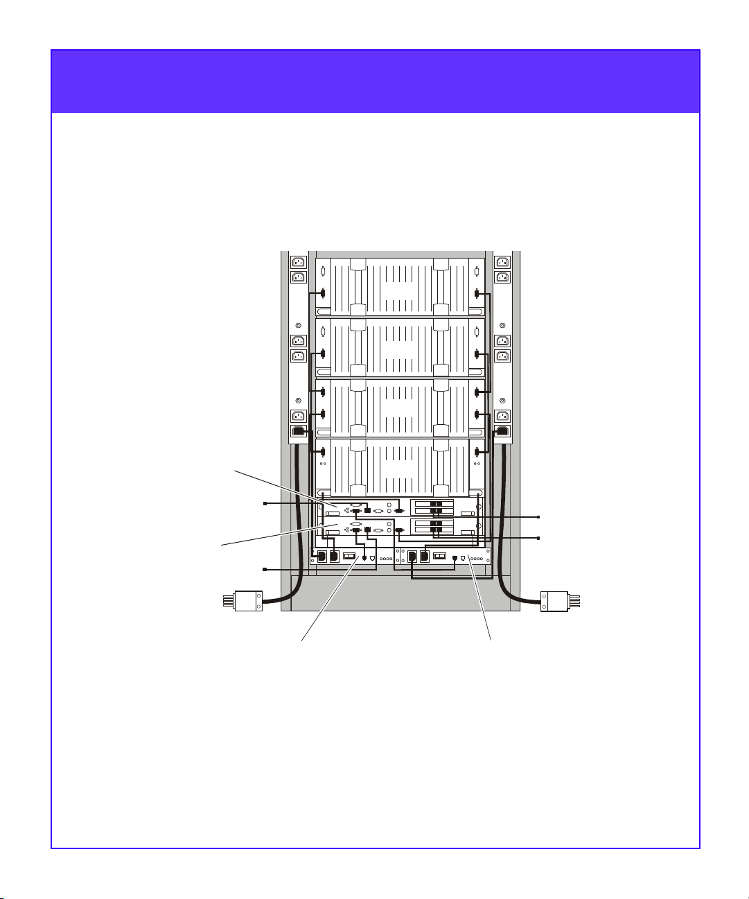
1. Confirm that electrical wiring is in place at your facility to
accommodate the cabinet’s two 240-volt ac power cables. To
support all of the FC4700 high-availability features, you must
connect each power outlet to a different circuit.
3
Page 6

Before You Start (continued)
2. Verify that your facility has adequate network wiring for your
sub-network (subnet) connections. To manage the storage
system, each storage processor (SP) requires a separate network
connection.
3. If your environment includes switches on the path between the
FC4700 and the hosts (servers) that have access to it, make sure
the switches are installed. Refer to the device-specific
installation manuals for each switch.
4. Verify that the Standby Power Supplies (SPSs), Disk Processor
Enclosure (DPE), and any optional Disk Array Enclosures
(DAEs) are installed in your cabinet. If necessary, refer to the
appropriate cabinet, rail, or device hardware installation
documentation you received with your system.
5. Have the network administrator at your facility set up IP
addresses for the FC4700 and complete the worksheet provided
in Step 1 on page 5.
6. Make sure that the latest revisions of Navisphere® Manager and
Event Monitor are installed on the Windows® 2000 or Windows
NT® host you will use as the Navisphere management station.
Refer to the EMC Navisphere Manager Administrator’s Guide,
EMC Navisphere Event Monitor Administrator’s Guide, and the
appropriate Release Notes as necessary.
4
Page 7

Step 1
Gather Network Information
SP-A SP-B
Hostname
_______________ _______________
Up to 15 alphanumeric characters. Dashes are acceptable.
Special characters such as dots, spaces, or underscores are
not allowed. Examples: Array1-A, Array1-B.
IP Address _______________ _______________
Subnet Mask _______________ ______________
Gateway _______________ ______________
Step 2
Verify Power Supply Settings
1. Remove the disk drive fan pack.
2. Confirm that the power switch on each power supply behind the
fan pack is on, then replace the fan pack.
Power
switch
Disk drive
fan pack
Power
switch
5
Page 8
Step 3
B
Confirm the Standby Power Supply (SPS) Connections
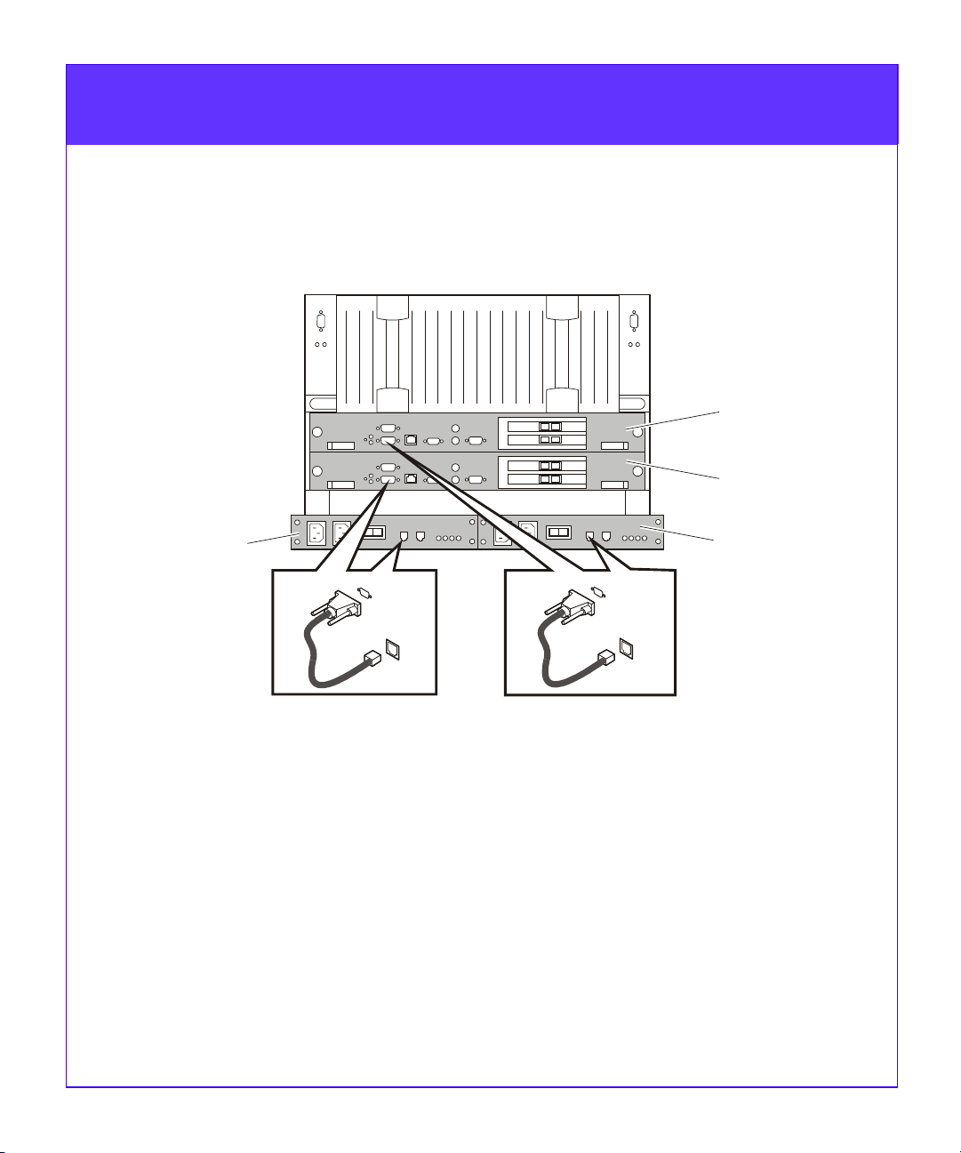
In most cases, standby power supplies are connected to the storage
processors prior to shipment. Verify that your FC4700 SPS connections
are correct and fully seated.
SP-B
SP-A
SPS-A
COM2
COM2
SPS-
EMC1994
1. Standby power supply A (SPS-A) connects to the lower serial port
(COM2) of SP-A.
2. Standby power supply B (SPS-B) connects to the lower serial port
(COM2) of SP-B.
6
Page 9
Step 4
Start the FC4700
Circuit
breaker
SPS-A
power
switch
Circuit
breaker
SPS-B
power
switch
EMC1995
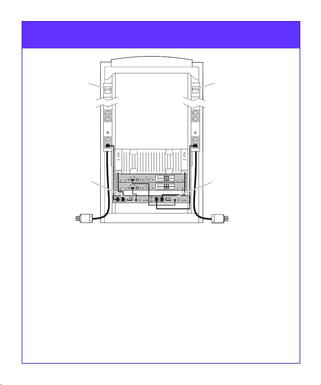
1. Plug the two 240-volt ac power cables into the power outlets in
your facility. We recommend connecting each power cable to a
different branch circuit. Both power cables must be connected to
the appropriate power supply. Connecting only one power source
will degrade the FC4700’s performance.
2. Turn on the circuit breakers on each of the cabinet’s side power
strips.
3. Turn on the power switch on each standby power supply.
If warning lights appear on the front of the DPE, make sure the system is
correctly cabled and then refer to the fault code explanations in Chapter 4
of the FC4700 Hardware Reference. If you cannot determine any reasons
for errors, contact your FC4700 service provider. (Operators with valid
contracts can contact EMC Customer Service at USA (800) 782-4362,
Canada (800) 543-4782, or worldwide (508) 497-7901.)
7
Page 10
Step 5
A
Initialize the FC4700
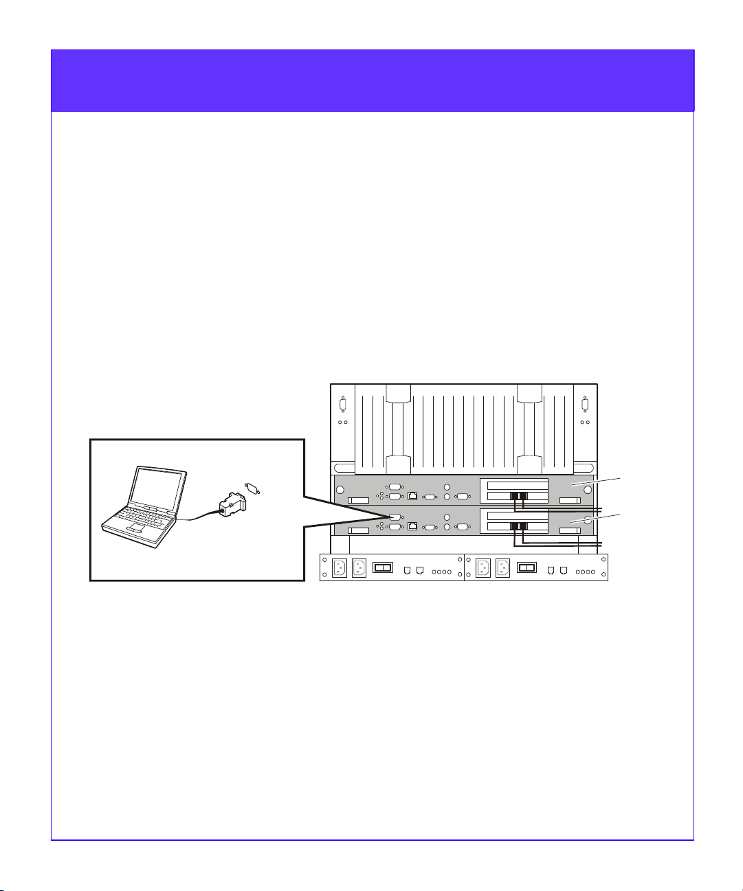
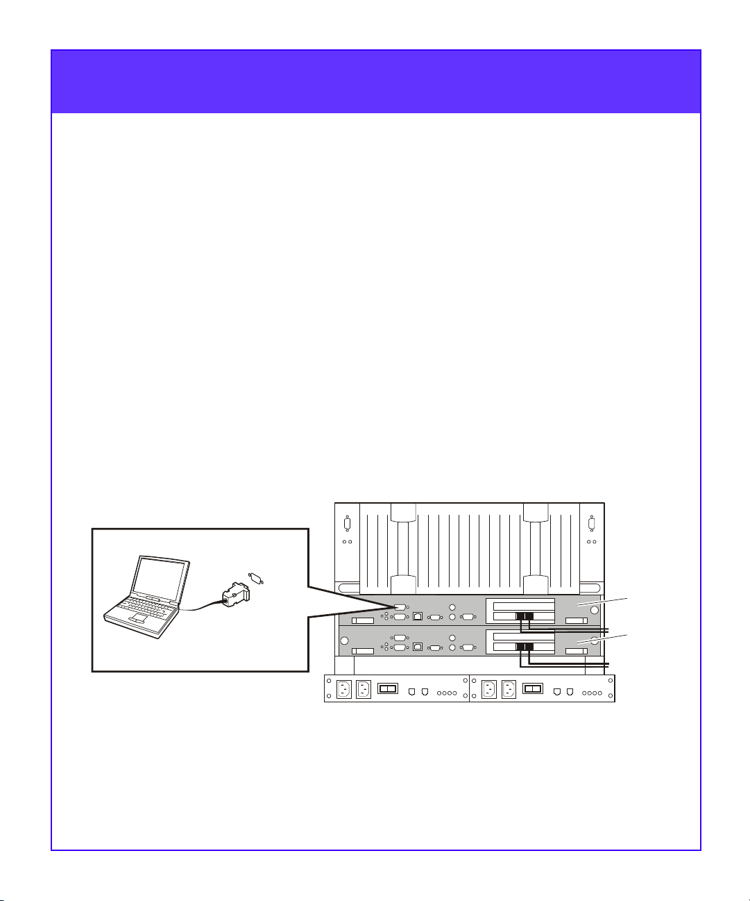
Initializing the FC4700 requires a directly connected computer -—
usually a laptop model — that we refer to as a service laptop.
IMPORTANT The following guidelines outline how experienced
technical personnel initialize an FC4700 storage system. For
explanations and detailed initialization instructions, refer to
Chapter 3 in the FC4700 Rackmount Model Hardware Reference.
Service Laptop Setup
1. Connect the service laptop to the serial port on SP-A with the
null modem cable.
COM1
RS-232 cable
Service
laptop
2. Make sure Dial-Up Networking between 2 PCs is installed
and set up on the service laptop.
3. Set up Dial-Up Networking.
4. Modify the laptop’s TCP/IP network settings to use DHCP.
8
SP-B
SP-
EMC1996
Page 11
Initialize the FC4700 (continued)
A
Critical Parameter Setup
On the FC4700:
5. Set up a user account.
6. Create the Persistent Storage Management (PSM) LUN.
7. Specify privileged users for the FC4700.
8. Set the SPS test time for each SPS in your system.
Network Information Setup
9. Specify the hostname, IP address, subnet mask, and gateway
address for SP-A. Use the information you collected and entered
earlier in Step 1, Gather Network Information.
10.Disconnect the service laptop from SP-A and connect it to the
serial port on SP-B.
Step 5
COM1
RS-232 cable
Service
laptop
11.Specify the hostname, IP address, subnet mask, and gateway
address for SP-B. Use the information you collected and entered
earlier in Step 1, Gather Network Information.
9
SP-B
SP-
EMC1997
Page 12
Initialize the FC4700 (continued)
SP ALPHA SCSI ID Setup
12.Use Navisphere Manager to select each FC4700 SP Agent to be
managed.
13.Set the ALPHA SCSI ID value for each port on SP-A and SP-B.
Setup Confirmation
14.Make certain all software packages are committed. In
Navisphere Manager, check the Software tab of the Array
Properties selection for any software packages requiring a
COMMIT. Perform the commit if necessary.
NOTE Keep the service laptop connected until you have tested
the LAN connections to the Navisphere management station.
Step 5
Step 6
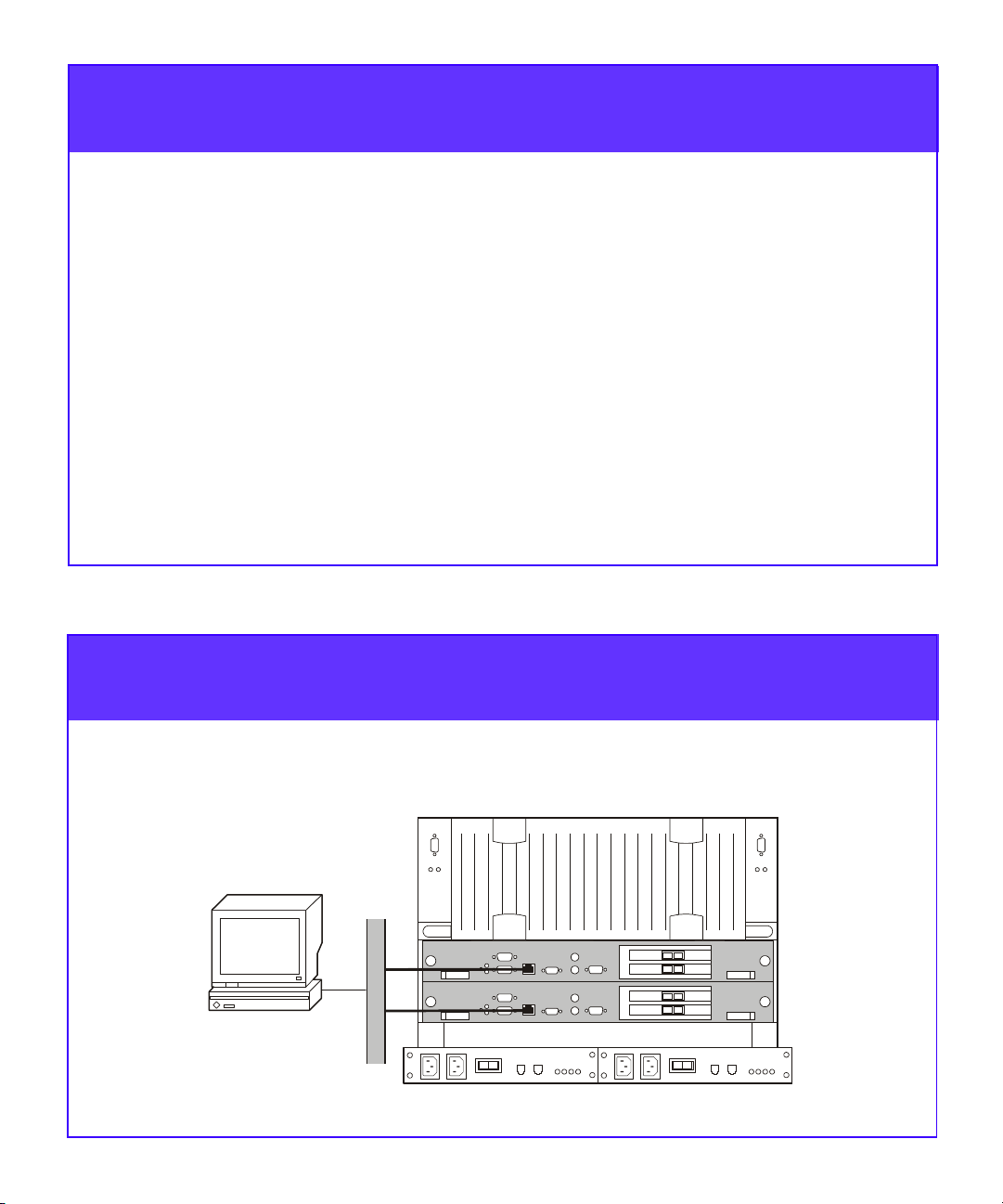
Connect a Management Station
Connect each SP separately to the LAN to which your Navisphere
management station is connected.
.
Management
station
LAN
EMC1991
10
Page 13

Step 7
Configure the FC4700 System
Configure the storage system using Navisphere Manager from the
Navisphere management station.
IMPORTANT The following steps summarize how to configure an
FC4700 storage system. For detailed instructions on each procedure,
refer to the EMC Navisphere Manager Administrator’s Guide.
1. Select the FC4700 storage system you want to configure.
Optional FC4700 Software Installation
2. If you have Access Logix™, SnapView, or MirrorView software,
install them in the same non-disruptive software installation
(NDU). Refer to the option-specific documentation as
appropriate.
Make certain all software packages are committed. In
Navisphere Manager, check the Software tab of the Array
Properties selection for any software packages requiring a
COMMIT. Perform the commit if necessary.
Remote SP Agent Configuration
3. Specify any additional privileged users for each SP.
Storage-System Properties Setup
4. Set the general configuration properties — enable automatic
polling, automatic polling priority, and SP-A and SP-B statistics
logging.
5. Set the read and write cache memory properties for each SP.
6. Set the FC4700 cache properties.
7. If the FC4700 is running Access Logix, set the data access
property.
Make Switch or Host Connections
11
Page 14
Step 8
A
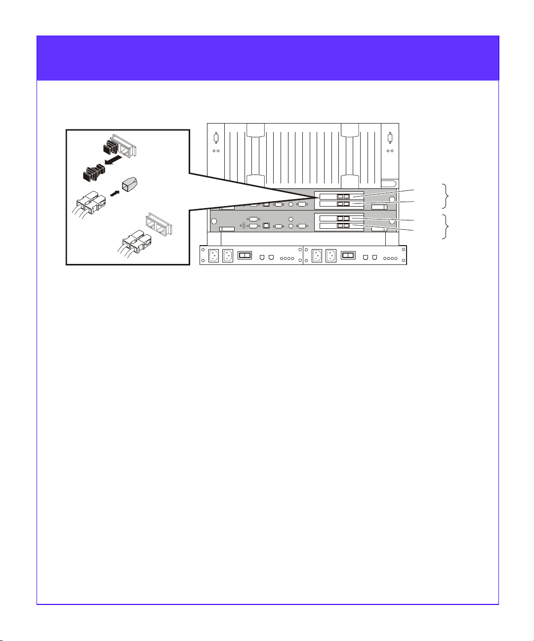
Make Switch or Host Connections
Por t 0
Por t 1
Por t 0
Por t 1
Optical
GBIC
cable
RX
TX
1. Remove the protective covers from each optical GBIC connector
and cable.
2. Plug the cables into the SP host ports.
3. Connect the other end of the Port 0 (top) cable to:
• Direct attach — The host server’s host bus adapter (HBA).
NOTE If the HBA is not yet installed in the host server,
complete Step 9, then connect the SP.
• Storage Area Network (SAN) — A Fibre Channel switch port.
4. Connect the other end of the Port 1 (bottom) cable as follows:
• Without RemoteMirror — to an HBA port (direct-attach
configurations) or switch port (SAN configurations)
SP-B
SP-
EMC1992
• With RemoteMirror — to a storage processor (SP) host port on
the remote storage system.
12
Page 15

Step 9
Set Up the Hosts
HBA and Driver Installation
Complete the following tasks on each host that will use the storage
system.
IMPORTANT The following steps summarize how experienced
technical personnel set up FC4700 hosts. For explanations and
detailed instructions, refer to the EMC Fibre Channel Storage
System Model FC4700 Configuration Planning Guide, installation
instructions provided with the host bus adapter and its drivers, and
the host hardware documentation.
1. Install the host bus adapters (HBAs) in the host. Refer to the
• EMC Fibre Channel HBA and Driver Installation Guide and
• EMC Fibre Channel HBA/Driver Release Notes
appropriate for your operating system.
2. For a SAN configuration, connect each HBA to the appropriate
switch port.
3. For a direct attach configuration, connect each HBA to the
appropriate SP port.
4. Install the HBA driver and any utilities from the HBA media (if
appropriate) on each host.
Switch Zone Creation
Refer to the device-specific documentation provided with your Fibre
Channel switch(es) to complete the following:
5. On each switch fabric, create a zone for each HBA and all the SP
ports that you want the HBA to access. Use worldwide port
names (WWPNs) to specify the HBA and the SP ports for the
zone.
13
Page 16

Step 9
Set Up the Hosts (continued)
HBA and Driver Installation (continued)
6. Install CLARiiON® Driver Extension (CDE) software if CDE is
available for your host, and your configuration requires it.
• FC4700 storage systems support CDE in IBM AIX
Solaris®, and Microsoft Windows NT® and Windows® 2000
environments.
®
, Sun
• Configurations with only one host HBA require CDE.
7. Activate the driver. Depending on the host, you may need to
reboot the host.
Navisphere Host Software Installation
Refer to the appropriate EMC Navisphere Server Software Setup Guide
to complete the following for each host that will use the storage system.
1. If the host has multiple HBAs connected to the storage system
and Navisphere® Application Transparent Failover (ATF) is
available, install ATF.
FC4700 storage systems support ATF in AIX, NetWare, Solaris,
Windows NT and Windows 2000 environments.
2. Activate the ATF devices by rebooting the host.
3. Install the Navisphere Host Agent and optional CLI.
4. Start the Host Agent.
5. If you plan to install SnapView software, install the admsnap
host management utility software.
14
Page 17

Step 10
Create FC4700 Storage Groups
Create storage groups using Navisphere Manager from the Navisphere
management station.
IMPORTANT The following steps summarize the process for
creating storage groups in an FC4700 storage system. For detailed
instructions on each procedure, refer to the EMC Navisphere
Manager Administrator’s Guide.
LUN and Storage Group Creation
Refer to the worksheets you filled out in the EMC Fibre Channel
Storage System Model FC4700 Configuration Planning Guide as you
perform the following tasks.
1. Select the FC4700 storage system you want to configure.
2. Create the RAID Groups you want on the FC4700.
3. Bind one or more LUNs in each RAID Group.
4. When you have bound all the LUNs on an FC4700 without
Access Logix, reboot the server.
The host will now recognize the new LUNs. Skip the next procedures
and continue with Step 11, Complete the Host Setup.
5. If your system includes Access Logix, create each Storage Group
you want and assign it to the appropriate hosts.
• You can connect a host to only one Storage Group per array.
• You must connect clustered hosts to the same Storage Group.
6. Reboot the server before continuing with the next step.
15
Page 18

Step 11
Complete the Host Setup
Refer to the appropriate EMC Navisphere Server Software Setup Guide
to complete the following for each host that will use the storage system.
1. Make the LUNs for each host available to the host’s operating
system. Depending on the operating system, this may involve:
• Labeling and partitioning LUNs
• Making file systems or creating volumes on the partitions
• Mounting the file systems or volumes.
2. If hosts are clustered, set up the clustering software to work with
the FC4700.
16
Page 19

Step 12
Set Up MirrorView™ and SnapView™ Software (optional)
IMPORTANT If you purchased the MirrorView or the SnapView
option, refer to the EMC Navisphere Manager Administrator’s Guide
and the option-specific installation guides to complete the following
procedures.
MirrorView Setup
1. Allocate the write intent log if you plan to use it.
2. Create a remote mirror.
3. If desired, add a secondary image to the remote mirror.
SnapView Setup
1. If you do not have bound LUNs available for the snapshot cache,
bind them.
2. Configure the snapshot cache for each SP that owns LUNs for
which you want to create snapshots.
3. Add a snapshot to the Storage Group for the host that will access
it.
17
Page 20

Step 13
Set Up Event Monitor
Refer to the EMC Navisphere Event Monitor Administrator’s Guide to
complete the following tasks.
1. Plan your monitoring configuration (for example, whether to use
distributed or centralized monitoring).
2. Install Event Monitor on your management station from the
Event Monitor CD-ROM.
3. Set user options, create templates, and use Event Viewer to
configure Event Monitor.
Step 14
Set Up CLARalert® Remote Service
CLARalert Remote Service (CRS) is a highly recommended call-out/
dial-in service tool available to all EMC customers. It polls the
Navisphere agents in each host on a specified LAN, analyzes the agent
logs, and initiates a call to the EMC Customer Support Center when
warranted. A CRS connection also allows a qualified service engineer at
the Support Center to call an array to investigate events, verify
configurations, or monitor array operation.
CRS resides on a Navisphere management station running
Windows NT.
Qualified EMC service personnel will set up CLARalert Remote Service
without charge.
18
Page 21

Your Next Step
You are now ready to read and write to the FC4700 and to use
Navisphere Manager to activate remote mirrors or start a SnapView
session.
If You Need Help
These resources are available in case you encounter problems while
setting up or using the FC4700.
For questions about
• Storage system
configurations
• Configuration
planning
Use this resource
EMC Fibre Channel
Storage System Model
FC4700 Configurati on
Planning Guide
It contains Find it here
• Background
information
• Worksheets for
planning a storage
system environment
• Supported/suggested
configurations
19
• Documents and
Media box
Page 22

.
For questions about
If You Need Help (continued)
Use this resource
It contains Find it here
• Supported host bus
adapters and their
drivers
• Hardware
component
installation or
maintenance
• Managing the
storage system
• Navisphere host
software
• Storage system
software
HBA and driver
Release Notes
FC4700 Rackmount
Model Hardware
Reference
EMC Navisphere®
Manager
Administrator’s Guide
EMC Navisphere®
Server Software for
[your environment]
Administrator’s Guide
• Required software
environment
• Changes and
enhancements
• Notes and warnings
• Installation and
maintenance for
DPE components
• Storage system
concepts
• Instructions for
managing the
storage system
• Troubleshooting
• Glossary
•Environment-specific
information on:
- HBA drivers
- ATF
- Navisphere Agent
- CLI
• Documents and
Media box
• Documents and
Accessories box
• Documents and
Media box
• Documents and
Media box
• Last minute
changes to
documentation
Appropriate Release
Notes for your
operating system,
application(s), and
hardware
environment
• Required software
environment
• Changes and
enhancements
• Notes and warnings
• Documents and
Media box
For questions about technical support and service, contact your service
provider.
If you have a valid EMC service contract, contact EMC Customer
Service at USA (800) 782-4362, Canada (800) 543-4782, or worldwide
(508) 497-7901.
For questions about upgrades, contact your local sales office.
20
 Loading...