

Dell External OEMR R710, PowerEdge R710 Technical Manual
PowerEdge R710
Technical Guide
The Dell PowerEdge
R710, with the
performance of Intel®
Xeon® processors,
offers you a 2U rack
server to efficiently
address a wide range
of key business
applications.

Dell
This document is for informational purposes only. Dell reserves the right to make changes without
further notice to any products herein. The content provided is as is and without express or implied
warranties of any kind.
Dell, PowerEdge, and ReadyRails are trademarks of Dell, Inc. Citrix is a registered trademark and
XenServer is a trademark of Citrix Systems, Inc. and/or one or more of its subsidiaries, and may be
registered in the United States Patent and Trademark Office and in other countries. Intel and Xeon
are registered trademarks of Intel Corporation in the U.S. and other countries. Broadcom is a
registered trademark and NetXtreme is a trademark of Broadcom Corporation and/or its affiliates in
the United States, certain other countries and/or the EU. Matrox is a registered trademark of Matrox
Electronic Systems Ltd. Microsoft and SQL Server are either registered trademarks or trademarks of
Microsoft Corporation in the United States and/or other countries. Red Hat is a registered trademark
of Red Hat, Inc. in the United States and other countries. Linux is a registered trademark of Linus
Torvalds. Symantec and Altiris are trademarks owned by Symantec Corporation or its affiliates in the
U.S. and other countries. VMware is a registered trademark and vSphere is a trademark of VMware,
Inc. in the United States and/or other jurisdictions. Other trademarks and trade names may be used
in this document to refer to either the entities claiming the marks and names or their products. Dell
disclaims proprietary interest in the marks and names of others.
©Copyright 2011 Dell Inc. All rights reserved. Reproduction or translation of any part of this work
beyond that permitted by U.S. copyright laws without the written permission of Dell Inc. is unlawful
and strictly forbidden.
Revision 1 January 2011
PowerEdge R710 Technical Guidebook ii

Dell
Table of Contents
1 Product Comparison ........................................................................................... 7
1.1 Overview .................................................................................................. 7
1.1.1 Strong IT Foundation............................................................................... 7
1.1.2 Customer-Inspired Design ......................................................................... 7
1.1.3 Enhanced Virtualization ........................................................................... 7
1.1.4 Energy Efficient .................................................................................... 7
1.1.5 Easy to Manage ..................................................................................... 8
1.1.6 Dell Services ........................................................................................ 8
1.2 Comparison ............................................................................................... 8
2 Key Technologies ............................................................................................. 11
2.1 Overview ................................................................................................ 11
2.2 Detailed Information .................................................................................. 11
3 System Overview ............................................................................................. 12
4 Mechanical .................................................................................................... 15
4.1 Chassis Description..................................................................................... 15
4.2 Dimensions and Weight ................................................................................ 15
4.3 Front Panel View and Features ...................................................................... 15
4.4 Back Panel View and Features ....................................................................... 16
4.5 Power Supply Indicators ............................................................................... 16
4.6 NIC Indicators ........................................................................................... 17
4.7 Internal Chassis Views ................................................................................. 17
4.8 Rails and Cable Management ......................................................................... 18
4.8.1 ReadyRails Sliding Rails ......................................................................... 18
4.8.2 ReadyRails Static Rails .......................................................................... 19
4.9 Fans ...................................................................................................... 19
4.10 LCD Control Panel ...................................................................................... 19
4.11 Security .................................................................................................. 20
4.11.1 Cover Latch ....................................................................................... 20
4.11.2 Bezel ............................................................................................... 20
4.11.3 Hard Drive ......................................................................................... 20
4.11.4 TPM ................................................................................................. 21
4.11.5 Power Off Security ............................................................................... 21
4.11.6 Intrusion Alert .................................................................................... 21
4.11.7 Secure Mode ...................................................................................... 21
4.12 USB Key .................................................................................................. 21
4.13 Battery ................................................................................................... 21
4.14 Field Replaceable Units (FRU)........................................................................ 21
4.15 User Accessible Jumpers, Sockets, and Connectors ............................................... 21
5 Power, Thermal, Acoustic .................................................................................. 22
5.1 Power Efficiency ....................................................................................... 22
5.2 Main Power Supply ..................................................................................... 22
5.3 Power Supply Specifications .......................................................................... 23
5.4 Heat Dissipation ........................................................................................ 23
5.5 Environmental Specifications......................................................................... 23
5.6 Power Consumption Testing .......................................................................... 24
5.7 Maximum Input Amps .................................................................................. 25
5.8 Energy Smart Enablement ............................................................................ 25
5.9 Energy Star Compliance ............................................................................... 25
5.10 Acoustics ................................................................................................ 25
PowerEdge R710 Technical Guidebook iii

Dell
6 Processors ..................................................................................................... 27
6.1 Overview ................................................................................................ 27
6.2 Features ................................................................................................. 28
6.3 Supported Processors .................................................................................. 28
6.4 Processor Configurations .............................................................................. 29
6.4.1 Single Processor Configuration ................................................................. 29
6.4.2 Processor Power Voltage Regulation Modules (EVRD 11.1) ................................. 29
6.5 Processor Installation .................................................................................. 29
7 Memory ........................................................................................................ 30
7.1 Overview ................................................................................................ 30
7.2 DIMMs Supported ....................................................................................... 30
7.2.1 Memory Modes .................................................................................... 30
7.2.2 DIMM Population Rules .......................................................................... 31
7.3 Speed .................................................................................................... 31
7.4 DIMM Slots ............................................................................................... 32
7.5 Low Voltage DIMMs ..................................................................................... 32
7.6 Mirroring ................................................................................................. 32
7.7 Sparing ................................................................................................... 33
7.8 Memory Scrubbing...................................................................................... 33
7.9 Advanced ECC (Lockstep) Mode ...................................................................... 33
7.10 Optimizer (Independent Channel) Mode ............................................................ 33
7.11 Supported Configurations ............................................................................. 33
8 Chipset ........................................................................................................ 34
8.1 Overview ................................................................................................ 34
8.1.1 Intel I/O Hub (IOH) ............................................................................... 34
8.1.2 IOH QuickPath Interconnect (QPI) ............................................................. 34
8.1.3 IOH PCI Express ................................................................................... 34
8.1.4 Intel I/O Controller Hub 9 (ICH9) .............................................................. 34
9 BIOS ............................................................................................................ 36
9.1 Overview ................................................................................................ 36
9.2 Supported ACPI States ................................................................................. 36
9.3 I2C (Inter-Integrated Circuit) ......................................................................... 36
10 Embedded NICs/LAN on Motherboard (LOM) ............................................................. 38
11 PCI Slots ....................................................................................................... 39
11.1 Overview ................................................................................................ 39
11.2 PCI Express Risers ...................................................................................... 39
11.3 Express Card Specifications (x16) .................................................................... 39
11.4 Quantities and Priorities .............................................................................. 39
11.5 PCI Card Dimensions ................................................................................... 40
12 Storage ........................................................................................................ 41
12.1 Overview ................................................................................................ 41
12.2 Internal Hard Disk Drives .............................................................................. 41
12.2.1 Diskless Configuration Support ................................................................. 42
12.2.2 Hard Drive LED Indicators ....................................................................... 42
12.3 RAID Configurations .................................................................................... 42
12.4 Storage Controllers .................................................................................... 44
12.4.1 SAS 6/iR ........................................................................................... 44
12.4.2 PERC 6/i ........................................................................................... 44
12.4.3 PERC H200 ......................................................................................... 44
12.4.4 PERC H700 ......................................................................................... 45
12.5 Optical Drives ........................................................................................... 46
12.6 Tape Drives ............................................................................................. 46
PowerEdge R710 Technical Guidebook iv

Dell
12.7 External Storage Support ............................................................................. 46
13 Video ........................................................................................................... 47
14 Rack Information ............................................................................................. 48
14.1 Overview ................................................................................................ 48
14.2 Rails ...................................................................................................... 48
14.3 Cable Management Arm (CMA) ....................................................................... 50
14.4 Rack View ............................................................................................... 50
15 Operating Systems ........................................................................................... 53
16 Systems Management ........................................................................................ 54
16.1 Overview ................................................................................................ 54
16.2 Server Management .................................................................................... 54
16.3 Embedded Server Management ...................................................................... 55
16.4 Dell Lifecycle Controller and Unified Server Configurator ....................................... 55
16.5 Integrated Dell Remote Access Controller .......................................................... 55
16.6 iDRAC6 Express ......................................................................................... 56
16.7 iDRAC6 Enterprise ...................................................................................... 56
16.8 iDRAC6 Enterprise with Virtual Flash (vFlash) Media ............................................. 56
17 USB Peripherals .............................................................................................. 59
Appendix A. Certifications ..................................................................................... 60
A.1 Regulatory Certifications ............................................................................. 60
A.2 Product Safety Certifications ......................................................................... 60
A.3 Electromagnetic Compatibility ....................................................................... 61
A.4 Ergonomics, Acoustics and Hygienics ............................................................... 61
Appendix B. Additional Information and Options ........................................................... 62
Tables
Table 1. Feature Comparison to PowerEdge R610 and R810............................................... 8
Table 2. Product Features Summary ........................................................................ 12
Table 3. Power Supply Status ................................................................................ 17
Table 4. Power Supply Specifications ....................................................................... 23
Table 5. Environmental Specifications ...................................................................... 23
Table 6. Power Consumption Testing ....................................................................... 24
Table 7. Acoustical Performance ............................................................................ 25
Table 8. Intel Xeon 5500 and 5600 Processor Series Features ........................................... 27
Table 9. Supported Processors ............................................................................... 28
Table 10. Supported Hard Drives .............................................................................. 41
Table 11. Factory RAID Configurations ....................................................................... 42
Table 12. Storage Card Support Matrix ....................................................................... 45
Table 13. Graphics Video Modes .............................................................................. 47
Table 14. Supported Racks ..................................................................................... 49
Table 15. Rail Adjustability Ranges and Depth ............................................................. 50
Table 16. Unified Server Configurator Features and Description......................................... 55
Table 17. Features List for Base Management Functionality, iDRAC, and vFlash ...................... 57
Table 18. Product Safety Certifications ...................................................................... 60
Table 19. Electromagnetic Compatibility Certifications ................................................... 61
Table 20. Ergonomics, Acoustics and Hygienics ............................................................. 61
Table 21. Industry Standards .................................................................................. 62
PowerEdge R710 Technical Guidebook v

Dell
Figures
Figure 1. Chassis Dimensions ................................................................................. 15
Figure 2. Front View (3.5‖ Hard Drive Chassis) ............................................................ 16
Figure 3. Front View (2.5‖ Hard Drive Chassis) ............................................................ 16
Figure 4. Front View (With Optional Bezel) ................................................................ 16
Figure 5. Back View ............................................................................................ 16
Figure 6. Internal Chassis View .............................................................................. 18
Figure 7. Fan Gantry ........................................................................................... 19
Figure 8. Control Panel ....................................................................................... 20
Figure 9. Power Supplies ...................................................................................... 23
Figure 10. Memory Channels ................................................................................... 31
Figure 11. R710 Sliding Rails with Optional CMA ............................................................ 48
Figure 12. 2U Threaded Rack Adapter Brackets Kit ........................................................ 49
Figure 13. R710 Static Rails .................................................................................... 49
Figure 14. R710 Mounted in B1 Sliding Rails ................................................................. 51
Figure 15. R710 Mounted in the B1 Sliding Rails with the CMA ........................................... 51
Figure 16. R710 Mounted in the A2 Static Rails (2-post Center Mount Configuration) ................ 52
PowerEdge R710 Technical Guidebook vi

Dell
1 Product Comparison
1.1 Overview
The Dell™ PowerEdge™ R710 is a 2-socket 2U rack server that can help you operate efficiently and
lower total cost of ownership (TCO) with enhanced virtualization capabilities, improved energy
efficiency, and innovative system management tools.
1.1.1 Strong IT Foundation
You want a data center built for organic growth and the ability to scale based on your company’s
changing requirements. You need complete solutions that let you focus your time and money on
managing and growing your business. Dell responds with an expanding portfolio of enterprise servers,
storage technologies, and services with a single goal: to help you simplify IT. The PowerEdge R710 is
designed for versatility and high performance, providing many of the virtualization, system
management, and energy-efficiency features you need now with the necessary scalability to change
as your business grows.
1.1.2 Customer-Inspired Design
Dell PowerEdge 11th generation servers are designed to meet customer needs with excellent
reliability, security, and commonality, making your experience easier. With Dell’s system
commonality, once your IT managers learn one system, they understand how to manage nextgeneration Dell servers. Logical component layout and power supply placement provide a
straightforward installation and redeployment experience. The PowerEdge R710 provides an
interactive LCD for alerting and control of basic management. The LCD also provides system health
monitoring and checks the AC power meter and ambient temperature monitor that is included with
each server. The PowerEdge R710 features robust metal hard drive carriers and organized cabling,
designed to help improve component access and airflow across the server for better reliability.
1.1.3 Enhanced Virtualization
Featuring embedded hypervisors, large memory capacity with 18 DIMM slots, and four integrated
network connections, the Dell PowerEdge R710 delivers better overall system performance and
greater virtual machine-per-server capacity. The latest Intel® Xeon® processor technology adapts to
your software in real-time, processing more tasks simultaneously. With optional factory-integrated
virtualization capabilities, you get tailored solutions that allow you to streamline deployment and
simplify virtual infrastructures. Choose your hypervisor from market leaders such as VMware®,
Citrix®, and Microsoft®, and enable virtualization with a few mouse clicks.
1.1.4 Energy Efficient
The PowerEdge R710 reduces power consumption while increasing performance capacity with Energy
Smart technologies such as right-sized efficient power supply units, improved system-level design
efficiency, and policy-driven power and thermal management. Dell’s advanced thermal control
delivers optimal performance at minimal power consumption without compromising enterprise
performance.
PowerEdge R710 Technical Guide 7
Dell
Feature
R610
R710
R810
Processor
Intel® Xeon®
processor 5500 and
5600 series
Intel® Xeon®
processor 5500 and
5600 series
Intel® Xeon®
processor 6500 and
7500 series
Form Factor
1U rack
2U rack
2U rack
Front Side Bus
Intel® QuickPath
Interconnect (QPI)
Intel® QuickPath
Interconnect (QPI)
Intel® QuickPath
Interconnect (QPI)
# Sockets
2 2 4
# Cores
2, 4, or 6
2, 4, or 6
4, 6, or 8
L2/L3 Cache
4MB, 8MB, and 12MB
4MB, 8MB, and 12MB
12MB, 18MB, or
24MB (shared)
Chipset
Intel® 5520
Intel® 5520
Intel® 7500
DIMMs
12 DDR3
18 DDR3
32 DDR3
Min/Max RAM
1GB/192GB
1GB/288GB
1GB/512GB
1.1.5 Easy to Manage
The PowerEdge R710 lets you devote more focus to running your business. The Dell OpenManage™
suite offers enhanced operations and standards-based commands designed to integrate with existing
systems for effective control.
Lifecycle Controller, the optional advanced embedded systems management engine, automates
common management tasks and gives you zero-media, low-touch deployment that is efficient, secure
and user-friendly. Lifecycle Controller works with the standard iDRAC Express or optional iDRAC
Enterprise to help simplify administrator tasks by performing a comprehensive set of provisioning
functions such as system deployment, system updates, hardware configuration, and diagnostics from
a single intuitive interface called Unified Server Configurator (USC) in a pre-OS environment. This
helps eliminate the need to use and maintain multiple pieces of disparate CD/DVD media. With Dell
Lifecycle Controller server deployment automation, the R610 can be up and running fast.
Dell Management Console (DMC), powered by Altiris™ from Symantec™, delivers a single view and a
common data source into the entire infrastructure. DMC is an easily extensible, modular foundation
that can provide basic hardware management or more advanced functions such as asset and security
management. It helps reduce or eliminate manual processes so less time and money is spent keeping
the lights on and more time can be spent on strategic uses of technology.
1.1.6 Dell Services
Dell Services can help reduce IT complexity, lower costs, and eliminate inefficiencies by making IT
and business solutions work harder for you. The Dell Services team takes a holistic view of your needs
and designs solutions for your environment and business objectives while leveraging proven delivery
methods, local talent, and in-depth domain knowledge for the lowest TCO.
1.2 Comparison
Table 1. Feature Comparison to PowerEdge R610 and R810
PowerEdge R710 Technical Guide 8

Dell
Feature
R610
R710
R810
Drive Bays
6 x 2.5‖
4 x 3.5" with optional
flex bay,
6 x 3.5" without flex
bay, or
8 x 2.5‖
6 x 2.5‖
Hard Drive Types
Hot-plug SAS and
SATA, nearline SAS
and SSD
Hot-plug SAS and
SATA, nearline SAS
and SSD
Hot-plug SAS and
SATA, SATA SSD
External Drive
Bay(s)
Optional internal
SATA slimline optical
drives such as DVDROM or DVD+RW
Optional flex bay
expansion to support
half-height tape
backup unit
N/A
Embedded Hard
Drive Controller
PERC 6/i, SAS 6/iR,
PERC H200, PERC
H700
PERC 6/i, SAS 6/iR,
PERC H200, PERC
H700
PERC H200, PERC
H700
Optional Storage
Controller
Non-RAID:
SAS 5/E
LSI 2032 (for tape
backup unit only)
6Gps SAS HBA
RAID:
SAS 6/iR
PERC 6/i
PERC 6/E
PERC H200
PERC H700
PERC H800
Non-RAID:
SAS 5/E
LSI 2032 (for tape
backup unit only)
6Gps SAS HBA
RAID:
SAS 6/iR
PERC 6/i
PERC 6/E
PERC H200
PERC H700
PERC H800
Non-RAID:
SAS 5/E
LSI 2032 (for tape
backup unit only)
6Gps SAS HBA
RAID:
PERC H200
PERC H700
PERC H800
Availability
Hot-plug hard drives,
hot-plug redundant
power and cooling,
ECC memory,
Single Device Data
Correction (SDDC),
memory demand and
patrol scrubbing,
high-availability
failover cluster
Hot-plug hard drives,
hot-plug redundant
power and cooling,
ECC memory,
Single Device Data
Correction (SDDC),
memory demand and
patrol scrubbing,
high-availability
failover cluster
Hot-plug hard
drives,
hot-plug redundant
power,
ECC memory,
dual internal SD
module
Server
Management
iDRAC6 Express, BMC,
IPMI 2.0, Dell
OpenManage™
Optional: iDRAC6
Enterprise, vFlash
iDRAC6 Express,
BMC, IPMI 2.0, Dell
OpenManage™
Optional: iDRAC6
Enterprise, vFlash
iDRAC6 Express,
BMC, IPMI 2.0, Dell
OpenManage™
Optional: iDRAC6
Enterprise, vFlash
I/O Slots
2 PCIe x8 G2
2 PCIe x8 + 2 PCIe x4
G2 or
1 x PCIe x16 + 2 PCIe
x4 G2
5 PCIe x8 + 2 PCIe
x4
PowerEdge R710 Technical Guide 9

Dell
Feature
R610
R710
R810
RAID
SAS 6/iR and PERC
H200: RAID 0, 1
PERC 6/i and PERC
H700: RAID 0, 1, 5, 6,
10, 50, 60
SAS 6/iR and PERC
H200: RAID 0, 1
PERC 6/i and PERC
H700: RAID 0, 1, 5,
6, 10, 50, 60
PERC H200:
RAID 0, 1
PERC H700/H800:
RAID 0, 1, 5, 6, 10,
50, 60
NIC/LOM
Broadcom®
BCM5709C
4 x iSCSI TOE
Optional: various NICs
available
Broadcom®
BCM5709C
4 x iSCSI TOE
Optional: various
NICs available
Broadcom®
BCM5709C
4 x iSCSI TOE
Optional: various
NICs available
USB
2 front, 2 back,
1 internal
2 front, 2 back,
1 internal
2 front, 4 back,
1 internal
Power Supplies
Two redundant hotplug high-efficiency
502W or
two redundant hotplug high-output
717W
Two redundant hotplug high-efficiency
570W or
two redundant hotplug high-output
870W
Two redundant hotplug 1100W
Fans
Six dual-rotor fans
(dual processor
configuration) or
five dual-rotor fans
(single processor
configuration)
Five hot-plug fans
(default processor
configuration) or
four hot-plug fans
(single processor
configuration)
Six hot-plug fans
PowerEdge R710 Technical Guide 10

Dell
2 Key Technologies
2.1 Overview
Key features of the PowerEdge R710 include dual Intel® Xeon® 5500 and 5600 series quad-core and
six-core processors, Intel® 5520 I/O Hub (IOH) with QuickPath Architecture, DDR3 memory, DIMM
thermal sensors, PCI Express Generation 2, iDRAC with integrated video controller, dual-port
embedded Gigabit Ethernet controllers, Internal SD Module, iDRAC6 Express, and optional iDRAC6
Enterprise.
2.2 Detailed Information
The Intel® Xeon® processor 5500 and 5600 series is designed specifically for servers and workstation
applications. The processor features quad-core and six-core processing to maximize performance and
performance/watt for data center infrastructures and highly dense deployments. The processor also
features the Intel Core™ micro-architecture and Intel 64 architecture for flexibility in 64-bit and 32bit applications and operating systems. See section 6 for more information.
PowerEdge R710 Technical Guide 11
Dell
Feature
Technical Specification
Form Factor
2U rack
Processors
Dual-core, quad-core, or six-core Intel® Xeon® processor 5500 and
5600 series
Processor Sockets
2
Front Side Bus or
HyperTransport
Intel® QuickPath Interconnect (QPI) (maximum 6.4GT/s)
Cache
Up to 12MB
Chipset
Intel® 5520
Memory1
Up to 288GB (18 DIMM slots): 1GB/2GB/4GB/8GB/16GB DDR3
800MHz, 1066MHz, or 1333MHz
I/O Slots
2 PCIe x8 + 2 PCIe x4 Gen2 or
1 x16 + 2 x4 Gen2
RAID Controller
Internal Controllers:
PERC H200 (6Gb/s)
PERC H700 (6Gb/s) (non-
volatile battery-backed cache:
512MB, 1G)
SAS 6/iR
PERC 6/i (battery-backed
cache: 256MB)
External Controllers:
PERC H800 (6Gb/s) (non-volatile
battery-backed cache: 512MB, 1G)
PERC 6/E (battery-backed cache:
256MB, 512MB)
External HBAs (non-RAID):
6Gb/s SAS HBA
SAS 5/E HBA
LSI2032 PCIe SCSI HBA
Drive Bays
Up to four 3.5‖ drives with optional flex bay,
up to six 3.5‖ drives without flex bay, or
up to eight 2.5‖ SAS or SATA drives with flex bay
Optional flex bay expansion supports half-height tape backup unit
(TBU)
Peripheral bay options:
Slim optical drive bay with choice of DVD-ROM, Combo CD-RW/DVD-
ROM, or DVD+RW
Maximum Internal
Storage
12TB (with 2TB 3.5‖ nearline SAS or SATA drives)
3 System Overview
For the latest information on supported features for the PowerEdge R710, visit Dell.com.
Table 2. Product Features Summary
PowerEdge R710 Technical Guide 12

Dell
Feature
Technical Specification
Hard Drives1
2.5‖ SAS (10,000 rpm): 146GB,
300GB, 600GB
2.5‖ SAS (15,000 rpm): 73GB,
146GB
2.5‖ SATA II (7,200 rpm):
160GB, 250GB, 500GB, 1TB
2.5‖ nearline SAS (7,200 rpm):
500GB, 1TB
2.5‖ nearline SAS (7,200 rpm):
1TB
3.5‖ SATA (7,200 rpm): 250GB,
500GB, 1TB, 2TB
3.5‖ SATA (5,400 rpm): 2TB
3.5‖ 6Gps SAS (7,200 rpm): 2TB
3.5‖ SAS (10,000 rpm): 146GB,
600GB
3.5‖ SAS (15,000 rpm): 146GB,
300GB, 450GB, 600GB
3.5‖ nearline SAS (7,200 rpm):
500GB, 1TB, 2TB
2.5‖ SATA SSD: 50GB, 100GB
2.5‖ SAS SSD: 149GB
Solid State Storage Cards:
Fusion-io® 160IDSS—160GB ioDrive
PCIe solid state storage card
Fusion-io® 640IDSS—640GB ioDrive
Duo PCIe solid state storage card
Communications
Four embedded Broadcom®
NetXtreme II™ 5709C Gigabit
Ethernet NICs with failover and
load balancing; TOE (TCPIP
Offload Engine) supported on
Microsoft® Windows Server®
2003 SP1 or higher with
Scalable Networking Pack;
Optional 1GBe and 10GBe
add-in NICs:
Broadcom® NetXtreme II™
57711 Dual Port Direct Attach
10Gb Ethernet PCI-Express
Network Interface Card with
TOE and iSCSI Offload
Intel® Gigabit ET Dual Port Server
Adapter and Intel® Gigabit ET
Quad Port Server Adapter
Dual Port 10GB Enhanced Intel
Ethernet Server Adapter X520-DA2
(FcoE Ready for Future
Enablement)
Optional add-in NICs:
Brocade® CNA (1020) Dual Port
Server Adapter
Optional add in HBAs:
Brocade® 8 GB HBAs
Emulex® OCE10102-IX-DCNA iSCSI
HBA stand-up adapter
Power Supply
Energy Smart: redundant hot-plug high-efficient 570W or
High Output: redundant hot-plug 870W
Availability
DDR3 memory, hot-plug hard drives, optional hot-plug redundant
power supplies, dual embedded NICs with failover and load
balancing support, optional PERC6/i integrated daughtercard
controller with battery-backed cache (or other controllers with
battery-backed cache or non-volatile cache), hot-plug redundant
cooling, toolless chassis, fibre and SAS cluster support, validated for
Dell/EMC SAN
Video
Matrox® G200 with 8MB of cache
Remote Management
iDRAC6 Enterprise (optional)
Systems Management
Dell™ OpenManage™
Microsoft® System Center Essential (SCE) 2010 v2
PowerEdge R710 Technical Guide 13

Dell
Feature
Technical Specification
Rack Support
ReadyRails™ sliding rails with optional cable management arm for 4post racks (optional adapter brackets required for threaded hole
racks)
ReadyRails™ static rails for 2-post and 4-post racks
Operating Systems
Microsoft® Windows® Small Business Server 2008
Microsoft® Windows® Essential Business Server 2008
Microsoft® Windows Server® 2008 SP2, x86/x64 (x64 includes
Hyper-V™)
Microsoft® Windows Server® 2008 R2, x64 (includes Hyper-V™ v2)
Windows® HPC Server 2008 R2
Novell® SUSE® Linux® Enterprise Server
Red Hat® Enterprise Linux®
Sun® Solaris™
Optional Embedded Hypervisors:
Citrix® XenServer™
Microsoft® Hyper-V™ through Microsoft® Windows Server® 2008
VMware® vSphere™ 4.1 (including VMware ESX® 4.1 or VMware ESXi™
4.1)
For more information on the specific versions and additions, visit
www.dell.com/OSsupport.
Featured Database
Applications
Microsoft® SQL Server® solutions (see Dell.com/SQL)
Oracle® database solutions (see Dell.com/Oracle)
1
GB means 1 billion bytes and TB equals 1 trillion bytes; actual capacity varies with
preloaded material and operating environment and will be less.
PowerEdge R710 Technical Guide 14
Dell
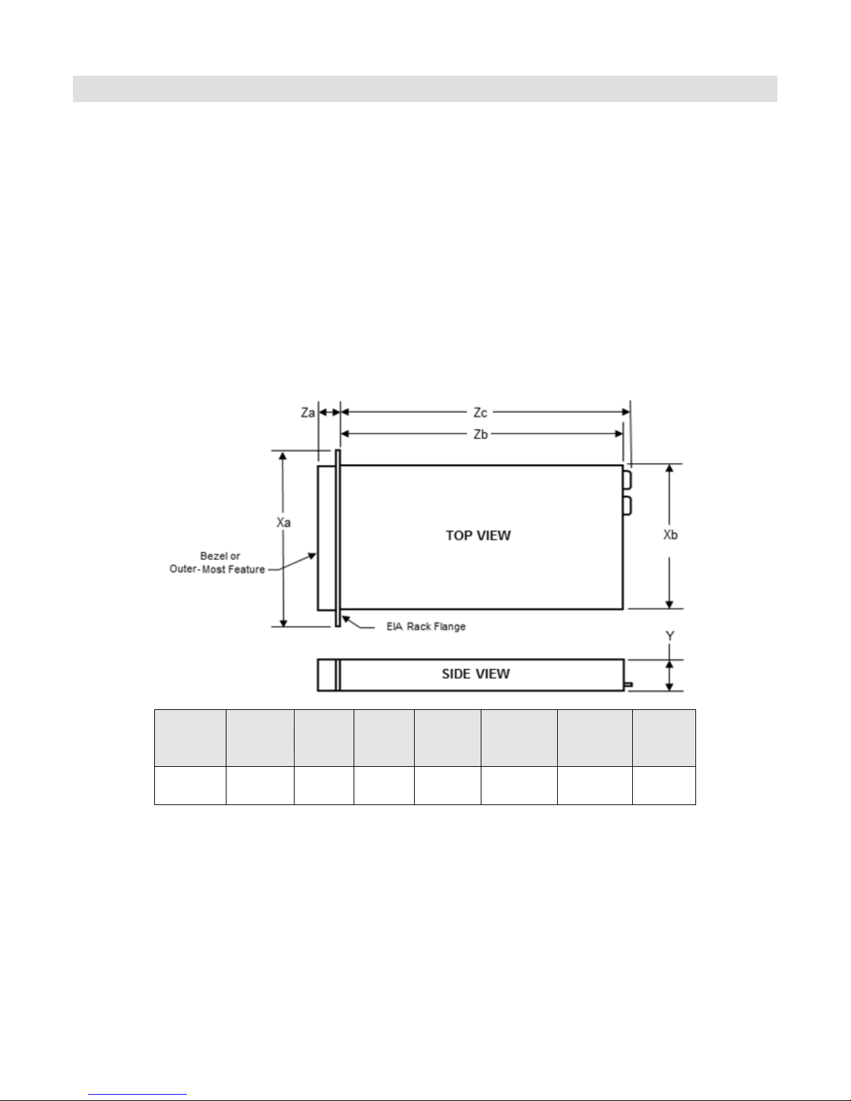
Xa
Xb
Y
Za
(With
Bezel)
Za
(Without
Bezel)
Zb
Zc
Max
Weight
482.4mm
443.1mm
86.4mm
35.0mm
23.5mm
680.7mm
720.6mm
26.1Kg
4 Mechanical
4.1 Chassis Description
The PowerEdge R710 is a 2U rack-mount design that supports the following features:
New LCD control panel, bezel, and hard-drive carriers
Toolless rack latches,
Pull-out tray for customer labels
Embedded NIC 1 and iDRAC MAC addresses
Support for persistent storage:
o Internal USB and SD card slot
o One external vFlash media slot (on optional iDRAC6 Enterprise card)
Updated power supplies and removal process
4.2 Dimensions and Weight
Figure 1 details the dimensions and weight for the PowerEdge R710.
4.3 Front Panel View and Features
The PowerEdge R710 is available in two chassis configurations: 3.5‖ hard drive chassis (see Figure 2)
and 2.5‖ hard drive chassis (see Figure 3).
PowerEdge R710 Technical Guide 15
Figure 1. Chassis Dimensions

Dell
Figure 2. Front View (3.5” Hard Drive Chassis)
Figure 3. Front View (2.5” Hard Drive Chassis)
Figure 4. Front View (With Optional Bezel)
See the Front-Panel Features and Indicators section in the About Your System chapter of the
PowerEdge R710 Hardware Owner’s Manual on Support.Dell.com for more information.
4.4 Back Panel View and Features
Figure 5 shows the back view of the PowerEdge R710 server.
Figure 5. Back View
See the Back-Panel Features and Indicators section in the About Your System chapter of the
PowerEdge R710 Hardware Owner’s Manual on Support.Dell.com for more information.
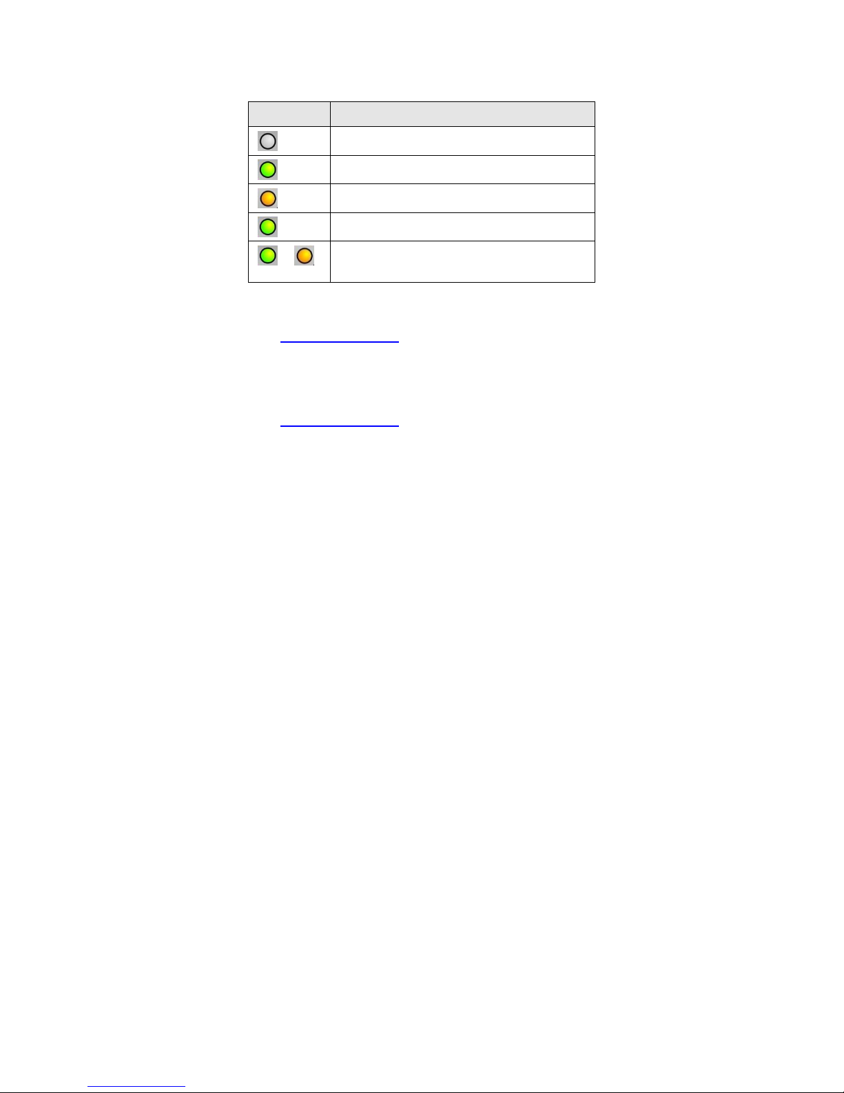
4.5 Power Supply Indicators
The PowerEdge R710 redundant power supplies have one status bi-color LED: green for AC power
present and amber for a fault as detailed in Table 3.
PowerEdge R710 Technical Guide 16
Dell
LED
Power Supply Status
AC Power is not present
AC Power is present
Fault of any kind is detected
DC Power is applied to the system
↔
Redundant power supply mismatch
(when hot-plugged/swapped)
Table 3. Power Supply Status
See the Power Indicator Codes section in the About Your System chapter of the PowerEdge R710
Hardware Owner’s Manual on Support.Dell.com for more information.
4.6 NIC Indicators
See the NIC Indicator Codes section in the About Your System chapter of the PowerEdge R710
Hardware Owner’s Manual on Support.Dell.com for more information.
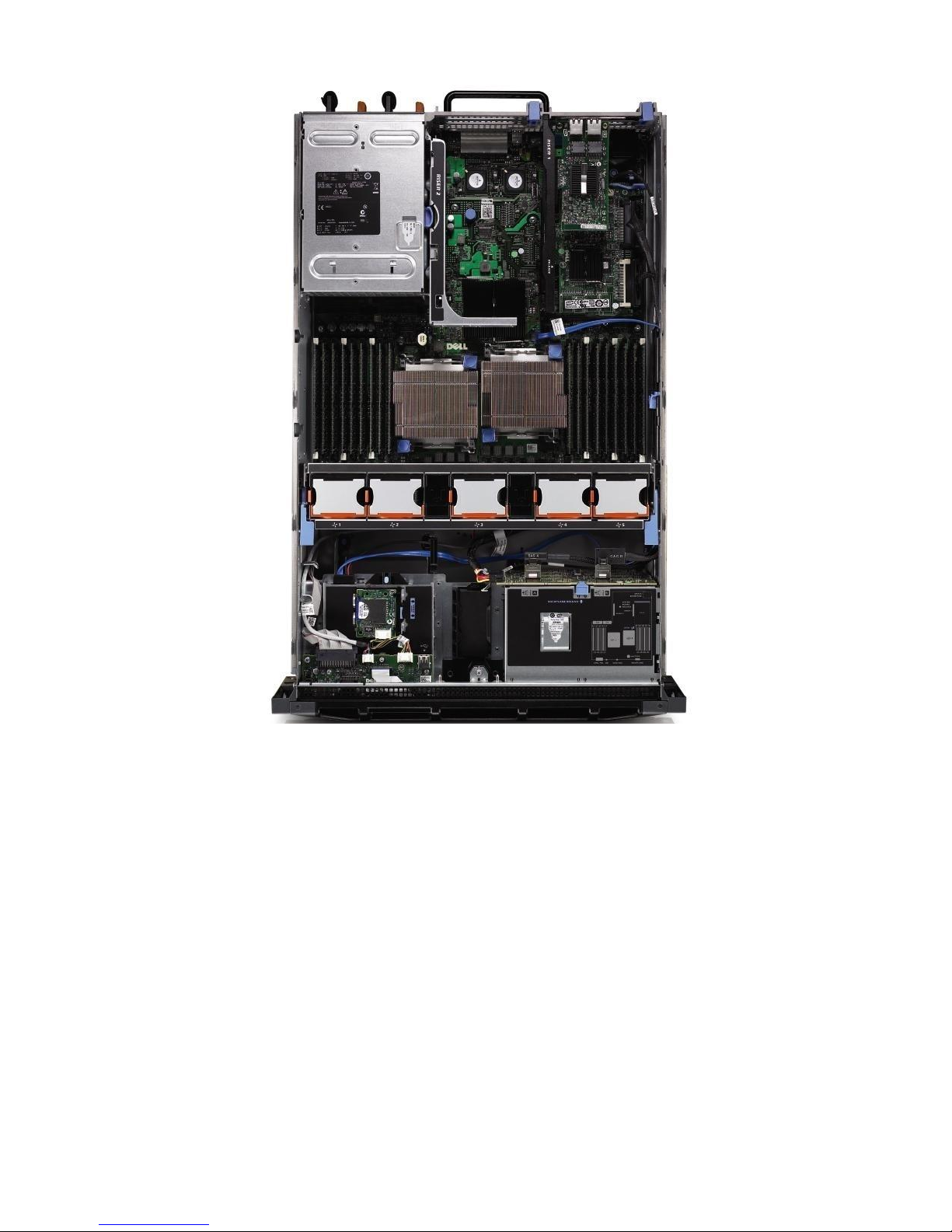
4.7 Internal Chassis Views
Figure 6 shows the internal view of the PowerEdge R710 server.
PowerEdge R710 Technical Guide 17
Dell
Figure 6. Internal Chassis View
4.8 Rails and Cable Management
4.8.1 ReadyRails Sliding Rails
ReadyRailsTM Sliding Rails for 4-post racks support the following:
Toolless installation in 19‖ EIA-310-E compliant square or unthreaded round hole 4-post racks
including all generations of Dell racks
Tooled installation in 19‖ EIA-310-E compliant threaded hole 4-post racks (requires the 2U
Threaded Rack Adapter Brackets Kit)
Full extension of the system out of the rack to allow serviceability of key internal components
Optional cable management arm (CMA)
PowerEdge R710 Technical Guide 18
Dell
4.8.2 ReadyRails Static Rails
ReadyRailsTM Static Rails for 4-post and 2-post racks support the following:
Toolless installation in 19‖ EIA-310-E compliant square or unthreaded round hole 4-post racks
including all generations of Dell racks
Tooled installation in 19‖ EIA-310-E compliant threaded hole 4-post and 2-post racks
See section 14 for more details.
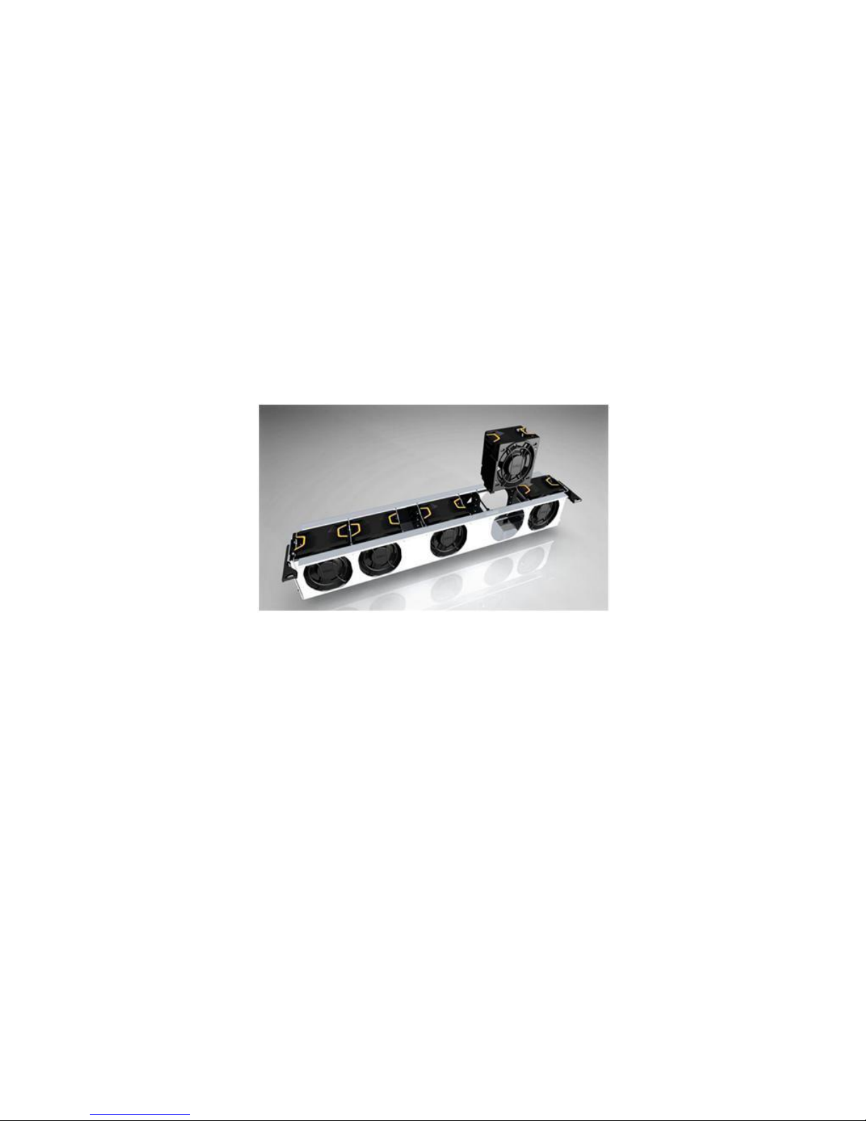
4.9 Fans
Five hot-swappable fans are mounted in a fan gantry that is located in the chassis between the hard
drive bay and the processors. See Figure 7. Each fan has a blind mate 2x2 connector that plugs
directly into the planar. There is an additional fan integrated in each power supply to cool the power
supply subsystem and also provide additional cooling for the whole system. Single processor
configurations have four fans populated.
Figure 7. Fan Gantry
The Embedded Server Management logic in the system monitors the speed of the fans. A fan failure
or over-temperature in the system results in a notification by iDRAC6. All system fans are pulse-width
modulated fans. Redundant cooling is supported.
4.10 LCD Control Panel
The LCD control panel is located on the front of the system chassis to provide user access to
switches, display, and I/O interfaces. See Figure 8. The control panel includes the following
features:
ACPI-compliant power button with an integrated green power LED (controlled by iDRAC6)
128x20 pixel LCD with controls:
o Two navigation buttons
o Select button
o System ID button
Non-maskable Interrupt (NMI) button (recessed)
Ambient temperature sensor
PowerEdge R710 Technical Guide 19
 Loading...