

Dell External OEMR R5500XL Setup & Features Manual
Dell Precision R5500
Setup And Features Information
About Warnings
WARNING: A WARNING indicates a potential for property damage, personal injury,
or death.
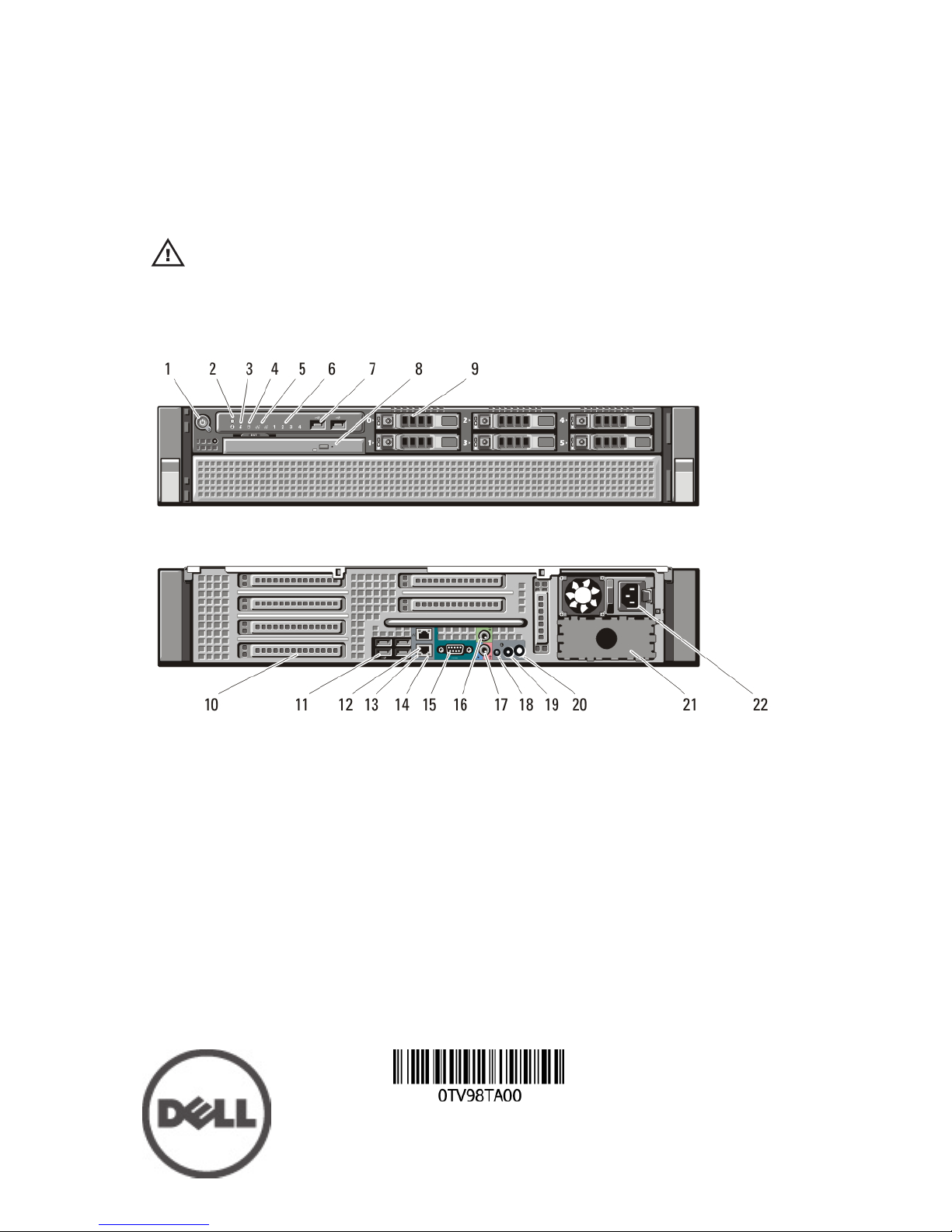
Front And Back View
Figure 1. Front And Back View
1. power button, power light
2. system identification button
3. system identification light
4. drive activity light
5. network link integrity lights (2)
6. diagnostic lights (4)
7. USB 2.0 connectors (2)
8. CD/DVD drive
9. hard drive bays (6)
10. expansion card slots
11. USB 2.0 connectors (4)
12. network adapter connector (2)
13. network link integrity light
14. network activity light
15. serial connector
16. line-out connector
17. line-in/microphone connector
18. system identification light
19. system identification button
Regulatory Model: E15S
Regulatory Type: E15S001
2011 – 04
20. remote system identification light
connector
21. second power supply bay (optional)
22. power connector
Quick Setup
WARNING: Before you begin any of the procedures in this section, read the safety
information that shipped with your computer. For additional best practices
information, see www.dell.com/regulatory_compliance.
NOTE: Some devices may not be included if you did not order them.
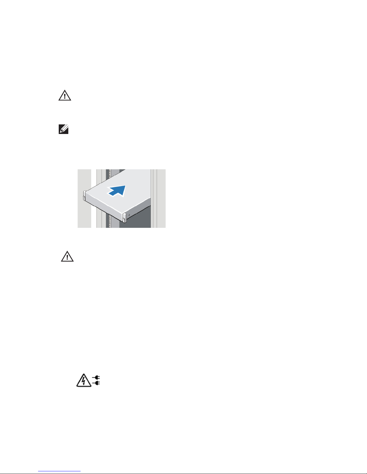
1. Install the rails and the computer in the rack. See your rack installation
documentation for safety instructions and instructions on installing
your computer in a rack.
Figure 2. Rack Installation
WARNING: Additional Instructions for Rack-Mounted Systems:
• Your rack kit has been approved only for the rack cabinet provided. It
is your responsibility to ensure that installation of the equipment
into any other rack complies with all applicable standards. Dell
disclaims all liability and warranties with respect to combinations of
equipment with any other rack.
• Before installing your equipment in a rack, install all front and side
stabilizers. Failure to install stabilizers can allow the rack to tip over.
• Always load from the bottom up, and load the heaviest items first.
• Do not overload the AC power supply branch circuit that provides
power to the rack.
• Do not stand or step on any components in the rack.
: The system may have more than one power supply cable. To
reduce the risk of electrical shock, a trained service technician may need
to disconnect all power supply cables before servicing the system.
2. Connect the network cable(s) (optional).
2
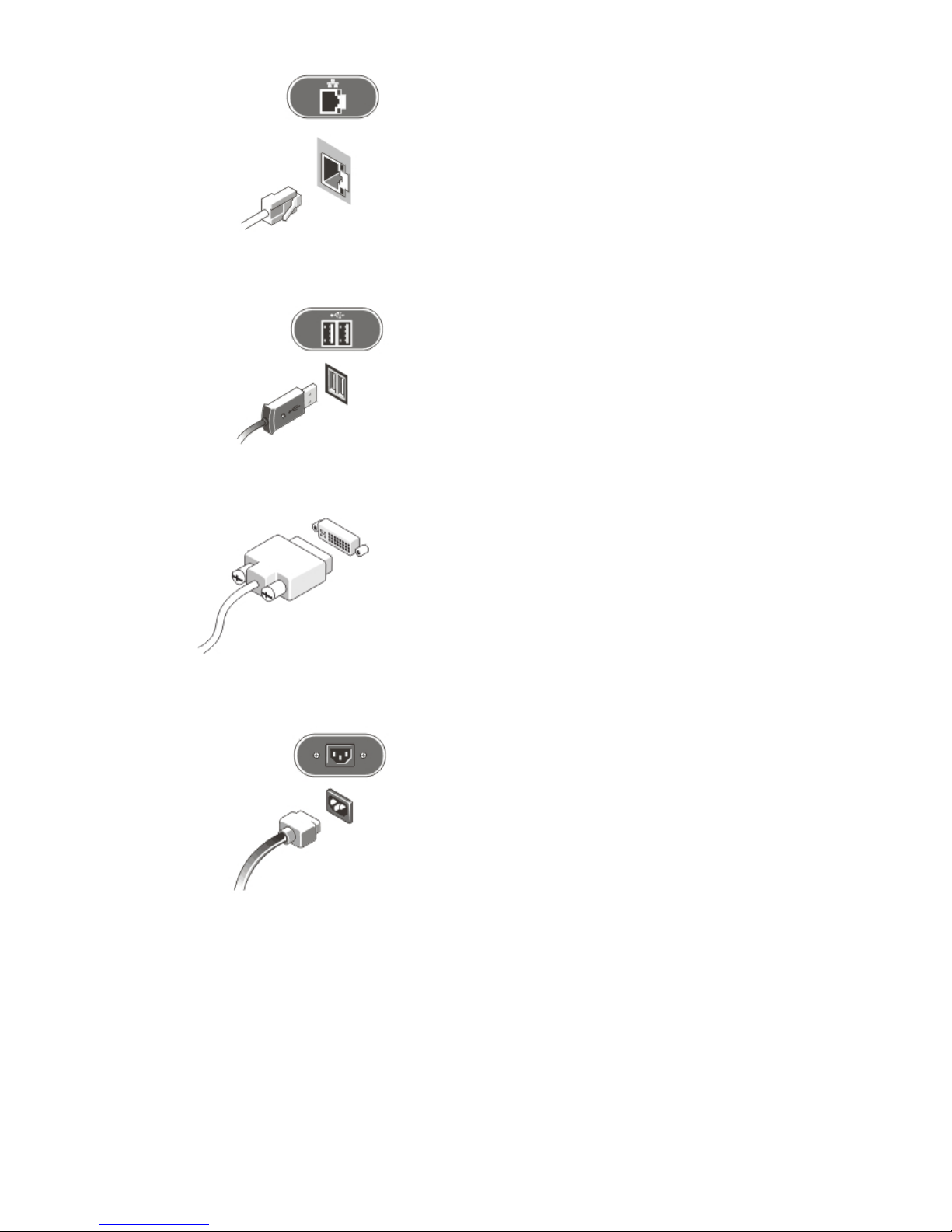
Figure 3. Network Connection
3. Connect the keyboard or mouse (optional).
Figure 4. Keyboard and Mouse Connection
4. Connect the monitor cable (optional).
Figure 5. Monitor Connection
5. Connect the power cable(s).
Figure 6. Power Connection
6. Bend the power cable into a loop and secure it to the power supply
handle using the strap.
3
 Loading...