

Dell External OEMR R410, PowerEdge R410 Technical Manual
PowerEdge R410
Technical Guide
Energy efficient and
compact, the
PowerEdge R410 is
designed with the
performance and
reliability needed for
High-Performance
Computing.

Dell
This document is for informational purposes only. Dell reserves the right to make changes without
further notice to any products herein. The content provided is as is and without express or implied
warranties of any kind.
Dell, PowerEdge, and ReadyRails are trademarks of Dell, Inc. Citrix® and XenServer™ are trademarks
of Citrix Systems, Inc. and/or one or more of its subsidiaries, and may be registered in the United
States Patent and Trademark Office and in other countries. Intel® and Xeon® are registered
trademark of Intel Corporation in the U.S. and other countries. HP and COMPAQ are trademarks of
Hewlett-Packard Company. Broadcom is a registered trademark and NetXtreme is a trademark of
Broadcom Corporation and/or its affiliates in the United States, certain other countries and/or the
EU. CommVault Galaxy® or Simpana® are registered trademarks of CommVault Systems, Inc.
InfiniBand is a registered trademark and service mark of the InfiniBand Trade Association. Matrox is a
registered trademark of Matrox Electronic Systems Ltd. Microsoft and SQL Server are either
registered trademarks or trademarks of Microsoft Corporation in the United States and/or other
countries. Mellanox is a registered trademark of Mellanox Technologies, Inc. and ConnectX,
InfiniBlast, InfiniBridge, InfiniHost, InfiniRISC, InfiniScale, and InfiniPCI are trademarks of Mellanox
Technologies, Inc. Red Hat is a registered trademark of Red Hat, Inc. in the United States and other
countries. Linux is a registered trademark of Linus Torvalds. Symantec and Backup Exec are
trademarks owned by Symantec Corporation or its affiliates in the U.S. and other countries. QLogic
and PathScale are registered trademarks of Qlogic Corporation. VMware is a registered trademark and
vSphere is a trademark of VMware, Inc. in the United States and/or other jurisdictions. Other
trademarks and trade names may be used in this document to refer to either the entities claiming
the marks and names or their products. Dell disclaims proprietary interest in the marks and names of
others.
©Copyright 2009–2010 Dell Inc. All rights reserved. Reproduction or translation of any part of this
work beyond that permitted by U.S. copyright laws without the written permission of Dell Inc. is
unlawful and strictly forbidden.
Revision 2 October 2010
PowerEdge R410 Technical Guide ii

Dell
Table of Contents
1 Product Comparison ........................................................................................... 7
1.1 Overview .................................................................................................. 7
1.2 Design for Usability ...................................................................................... 7
1.3 Energy Efficient .......................................................................................... 7
1.4 Easy to Manage ........................................................................................... 7
1.5 Comparison to Other Dell Servers ..................................................................... 8
2 System Overview ............................................................................................. 11
2.1 Overview ................................................................................................ 11
2.2 Product Features Summary ........................................................................... 11
3 Mechanical .................................................................................................... 14
3.1 Chassis Description..................................................................................... 14
3.2 Dimensions and Weight ................................................................................ 14
3.3 Front Panel View and Features ...................................................................... 15
3.4 Back Panel View and Features ....................................................................... 15
3.5 Power Supply Indicators ............................................................................... 16
3.6 NIC Indicators ........................................................................................... 17
3.7 Side Views ............................................................................................... 17
3.8 Rails and Cable Management ......................................................................... 18
3.8.1 ReadyRails Sliding Rails ......................................................................... 18
3.8.2 ReadyRails Static Rails .......................................................................... 18
3.9 Fans ...................................................................................................... 18
3.10 Control Panel/LCD ..................................................................................... 19
3.10.1 Cover Latch ....................................................................................... 20
3.10.2 Bezel ............................................................................................... 20
3.10.3 Hard Drive ......................................................................................... 20
3.10.4 Trusted Platform Management (TPM) ......................................................... 20
3.10.5 Power-Off Security ............................................................................... 20
3.10.6 Intrusion Alert .................................................................................... 20
3.10.7 Secure Mode ...................................................................................... 21
3.11 USB Key .................................................................................................. 21
3.12 Battery ................................................................................................... 21
3.13 Field Replaceable Units (FRU)........................................................................ 23
4 Power, Thermal, Acoustic .................................................................................. 24
4.1 Power Supplies ......................................................................................... 24
4.2 Power Supply Specifications .......................................................................... 24
4.3 Environmental Specifications......................................................................... 26
4.4 Maximum Input Amps .................................................................................. 27
4.5 Acoustics ................................................................................................ 27
5 Processors ..................................................................................................... 28
5.1 Overview ................................................................................................ 28
5.2 Processor Configurations .............................................................................. 28
5.3 Processor Installation .................................................................................. 28
6 Memory ........................................................................................................ 29
6.1 Overview ................................................................................................ 29
6.2 DIMMs Supported ....................................................................................... 29
6.3 Mirroring ................................................................................................. 29
6.4 Sparing ................................................................................................... 29
PowerEdge R410 Technical Guide iii

Dell
7 Chipset ........................................................................................................ 30
7.1 Overview ................................................................................................ 30
7.2 Intel 5500 Chipset Features .......................................................................... 30
7.2.1 Intel QuickPath Interconnect ................................................................... 30
7.2.2 System Memory Interface ....................................................................... 30
7.2.3 PCI Express* Interfaces .......................................................................... 31
7.2.4 SMBus Interfaces ................................................................................. 31
7.2.5 ESI interface ...................................................................................... 31
7.3 Intel ICH10R South Bridge ............................................................................. 31
7.3.1 DMI interface ..................................................................................... 31
7.3.2 SATA interface .................................................................................... 31
7.3.3 USB interface ..................................................................................... 31
7.3.4 PCI Express interface ............................................................................ 32
8 BIOS ............................................................................................................ 33
8.1 Overview ................................................................................................ 33
8.2 Supported ACPI States ................................................................................. 33
8.3 I2C (Inter-Integrated Circuit) ......................................................................... 34
9 Embedded NICs/LAN on Motherboard (LOM) ............................................................. 35
9.1 Overview ................................................................................................ 35
10 I/O Slots ....................................................................................................... 36
10.1 Overview ................................................................................................ 36
10.2 Quantities and Priorities .............................................................................. 36
10.3 Boot Order .............................................................................................. 37
11 Storage ........................................................................................................ 38
11.1 Overview with Description ............................................................................ 38
11.2 Drives .................................................................................................... 39
11.3 RAID Configurations .................................................................................... 39
11.4 Storage Controllers .................................................................................... 40
11.5 LED Indicators .......................................................................................... 41
11.6 Optical Drives ........................................................................................... 41
11.7 Tape Drives ............................................................................................. 41
12 Video ........................................................................................................... 42
13 Rack Information ............................................................................................. 43
13.1 Overview ................................................................................................ 43
13.2 Rails ...................................................................................................... 43
13.3 Cable Management Arm (CMA) ....................................................................... 45
13.4 Rack View ............................................................................................... 46
14 Operating Systems and Virtualization ..................................................................... 47
15 Systems Management ........................................................................................ 48
15.1 Overview/Description ................................................................................. 48
15.2 Server Management .................................................................................... 48
15.3 Embedded Server Management ...................................................................... 49
15.4 Lifecycle Controller and Unified Server Configurator ............................................ 49
15.5 iDRAC Express........................................................................................... 50
15.6 iDRAC6 Enterprise ...................................................................................... 50
16 Peripherals .................................................................................................... 53
16.1 USB Peripherals ......................................................................................... 53
16.2 External Storage ........................................................................................ 53
17 Packaging Options ........................................................................................... 54
PowerEdge R410 Technical Guide iv

Dell
Tables
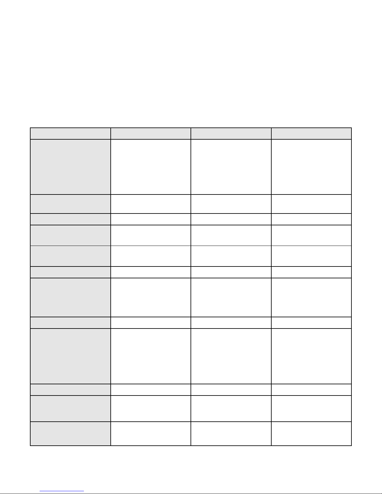
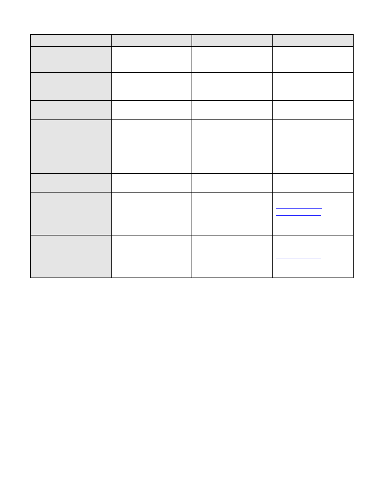
Table 1. Comparison of R410 to R310 and R510 ............................................................. 8
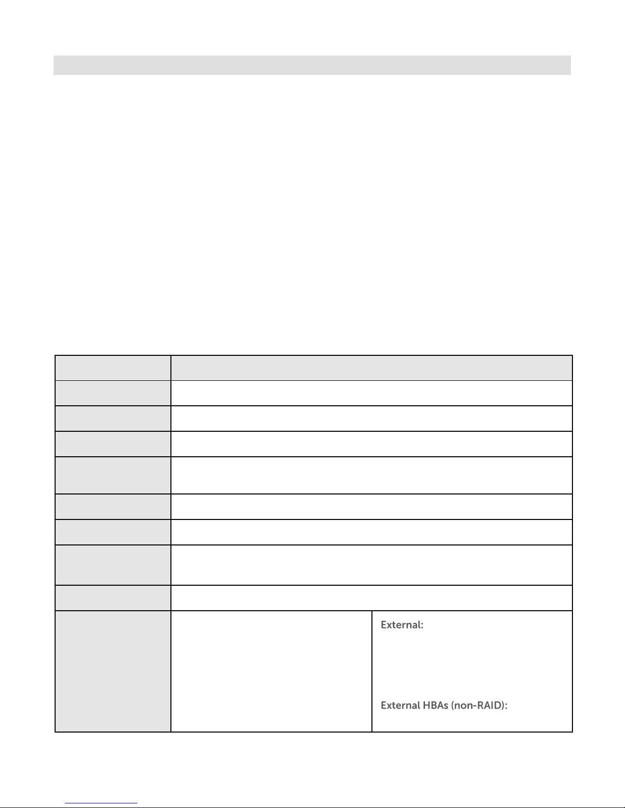
Table 2. PowerEdge R410 Features and Descriptions ..................................................... 11
Table 3. R410 Overall Dimensions and Weight ............................................................. 14
Table 4. NIC Indicator LED States ........................................................................... 17
Table 5. Power Supply Connector (24 pins) Signals ....................................................... 25
Table 6. Power Supply Connector (8 pins) Signals ........................................................ 26
Table 7. Operating/Non-Operating Storage Requirements .............................................. 26
Table 8. R410 Acoustical Information ....................................................................... 27
Table 9. Supported Processor Descriptions and Features ................................................ 28
Table 10. Wake-Up States ...................................................................................... 34
Table 11. Insert I/O Slot information......................................................................... 36
Table 12. Descriptions of R410 Controllers .................................................................. 36
Table 13. RAID Configurations ................................................................................. 39
Table 14. Rack Types Supported .............................................................................. 45
Table 15. Rail Adjustability Range and Rail Depth ......................................................... 45
Table 16. Unified Server Configurator Features and Description......................................... 49
Table 17. Features List for BMC, iDRAC, and vFlash ....................................................... 50
Table 18. R410 Volatility Table ............................................................................... 55
Figures
Figure 1. R410 Detailed Dimensions.......................................................................... 14
Figure 2. Front Without Bezel ................................................................................ 15
Figure 3. With Bezel View ..................................................................................... 15
Figure 4. Front Panel Controller .............................................................................. 15
Figure 5. With Redundant Power Supply .................................................................... 16
Figure 6. With Non-redundant Power Supply ............................................................... 16
Figure 7. Redundant Power Supply Units .................................................................... 16
Figure 8. Dual-Stacked RJ45 Connectors with NIC Indicators ............................................ 17
Figure 9. Left Side View ....................................................................................... 18
Figure 10. Right Side View ................................................................................... 18
Figure 11. R410 Fans .......................................................................................... 19
Figure 12. Front Controller Board with LCD ............................................................... 19
Figure 13. Front Controller Board with Diagnostic LED .................................................. 19
Figure 14. Chassis Intrusion Switch ......................................................................... 21
Figure 15. Battery Holder for PERC 6/i .................................................................... 21
Figure 16. Battery Holder for PERC ......................................................................... 22
Figure 17. Power Supply Connector (24 pins) ............................................................. 25
Figure 18. Power Supply Connector (8 pins) .............................................................. 25
Figure 19. Embedded NICs/LAN on Motherboard ......................................................... 35
Figure 20. Hot-Swap HDD Configuration with Backplane ................................................ 38
Figure 21. Top-View for Hot-Swap HDD Connection ..................................................... 38
Figure 22. Top-View for Cabled HDD Connection ......................................................... 38
Figure 23. Cabled HDD Connectors ......................................................................... 39
Figure 24. LED Indicators .................................................................................... 41
Figure 25. R410 Sliding Rails with Optional CMA ......................................................... 43
PowerEdge R410 Technical Guide v

Dell
Figure 26. 1U Threaded Rack Adapter Brackets Kit ...................................................... 44
Figure 27. R410 Static Rails .................................................................................. 44
Figure 28. R410 Mounted in the A3 Sliding Rails with the CMA ......................................... 46
Figure 29. R410 Mounted in the A4 Static Rails in 2-post Center Mount Configuration ............. 46
PowerEdge R410 Technical Guide vi

Dell
1 Product Comparison
1.1 Overview
The Dell™ PowerEdge™ R410 is ideal for compute-intensive applications in space-constrained
environments. It is a powerful, ultra-dense 2-socket 1U server that offers the performance of Intel®
Xeon® processor 5500 and 5600 series, DDR3 memory, and the availability of up to four hard drives
(3.5‖ or 2.5‖), and is an exceptional value.
The PowerEdge R410 features include an available ―open‖ HPCC (High Performance Computing
Cluster) software stack, excellent diagnostics with an interactive LCD, and an optimum chassis depth
of 24‖ for space-constrained data centers and HPCC environments.
The Dell PowerEdge R410 was developed with a customer-inspired design, energy-optimized
technology, advanced virtualization capabilities, and simplified systems management.
1.2 Design for Usability
The PowerEdge R410 follows the 11th generation PowerEdge portfolio specifications and features the
same system design commonality and reliability true to the entire portfolio. All 11th generation
servers are designed to make the user experience easier. We put all external ports, power supplies,
LCD screens, and LED lights in the same location for familiar experience as well as easy installation
and deployment.
Robust, metal hard drive carriers and organized cabling are designed to help improve component
access and airflow across the server. The PowerEdge R410 provides reduced complexity, showcasing
clutter-free cable routing for more efficient airflow and easier maintenance. An LCD screen
positioned by the front of the bezel provides aisle-level access to deploy the server.
1.3 Energy Efficient
The PowerEdge R410 features energy-tuned technologies that reduce power consumption while
increasing performance capacity so you can compute more while consuming less. It incorporates
Energy Smart design using low-flow fans and logical component layout of the internal components
which aids with airflow direction and policy-driven power and thermal management, helping to keep
the server cool and reduce noise as much as possible. A robust fan cage design with hot-plug, singlepull fan modules provides efficient airflow and eases maintenance. Energy efficient and compact,
the PowerEdge R410 is designed with value and reliability for HPCC environments.
1.4 Easy to Manage
With the optional advanced embedded systems management capabilities of Lifecycle Controller, Dell
provides comprehensive enterprise class manageability already on the motherboard. Lifecycle
Controller is delivered as part of the optional iDRAC Express or iDRAC Enterprise in the PowerEdge
R410. The Lifecycle Controller helps to simplify administrator tasks by performing a comprehensive
set of provisioning functions such as system deployment, system updates, hardware configuration and
diagnostics from a single intuitive interface called Unified Server Configurator (USC) in a pre-OS
environment. This helps eliminate the need to use and maintain multiple pieces of disparate CD/DVD
media.
PowerEdge R410 Technical Guide 7
Dell
Feature
R410
R310
R510
Processor
Quad-core or six-Core
Intel® Xeon® processors
5500 and 5600 series
Quad-Core Intel® Xeon®
processors 3400 series
Intel® Core™ i3-540
Intel® Core™ i3-530
Intel® Pentium® G6950
Intel® Celeron® G1101
Quad-core or six-Core
Intel® Xeon® processors
5500 and 5600 series
Front Side Bus
Intel® QuickPath
Interconnect (QPI)
®
Intel® Direct Media
Interface (DMI)
Intel® QuickPath
Interconnect (QPI)
# Processors
1 to 2
1
1 to 2
# Cores
2/4/6
Intel® Xeon®: Quad
DT proc: Dual
2/4/6
L2/L3 Cache
4MB, 8MB or 12MB
Intel® Xeon®: 8MB
DT proc: 4, 3 or 2M
4MB, 8MB or 12MB
Chipset
Intel® 5500 chipset
Intel® 3420
Intel® 5500 chipset
DIMMs
4+4 DDR3
Unbuffered with ECC or
Registered with ECC
1333/1066/800M Hz
DDR3
6 R-DIMMs or
4 U-DIMMs
4+4 DDR3
Unbuffered with ECC or
Registered with ECC
1333/1066/800M Hz
Minimum/Maximum RAM
1 GB/64 GB
1GB/32GB
HD Bays
4 x 3.5‖
Optional Hot-Swap
Support 2.5" HDDs via
Hot-Swap tray
4 x 3.5‖
Optional hot-swap
Or 2.5‖ SAS/ SSD via hot
swap chassis
4x 3.5‖
or
8x 3.5‖ or 2.5‖
or
12x 3.5‖ or 2.5‖ + 2x
internal 2.5‖
HD Types
SATA/SAS/SSD
SATA/SAS/SSD
SATA/SAS/SSD
External Drive Bay(s)
1 for slim ODD
1 for slim ODD
1 for slim ODD for 4 and
8-HDD chassis
configuration
Embedded HD Controller
Chipset-based SATA
Chipset-based SATA
Chipset-based SATA for 4HDD chassis
configuration. PERC HBA
Also part of the Dell OpenManage™ portfolio is the Dell Management Console which is included with
every Dell server and provides IT administrators with a consolidated console view of their IT
infrastructure. This console delivers a single view and a common data source into the entire
infrastructure management. It has an easily extensible, modular foundation that can provide basic
hardware management or more advanced functions, such as asset and security management. Dell
Management Console is designed to reduce or eliminate manual processes, enabling you to save time
and money for more strategic technology usage.
1.5 Comparison to Other Dell Servers
Table 1. Comparison of R410 to R310 and R510
PowerEdge R410 Technical Guide 8

Dell
Feature
R410
R310
R510
required for 8 and 12-HDD
chassis configuration.
Optional Storage
Controller
NON-RAID:
SAS 5/E
LSI2032 (For TBU only)
6Gbps SAS HBA
RAID:
SAS 6/iR Modular
PERC 6/i
PERC 6/E
PERC S300 Modular
PERC H200
PERC H700
PERC H800
NON-RAID:
SAS 5/E (Field Support
Only – No Factory Install)
LSI2032 (For TBU)
6Gbps SAS HBA
RAID:
PERC6/E (Field Support
Only)
SAS 5/E (Field Support
Only)
SAS 6/iR
PERC S300
H200
H700
H800
NON-RAID:
SAS 5/E
LSI2032 (For TBU only)
6Gbps SAS HBA
RAID:
SAS 6/iR Integrated
PERC 6/i Integrated
PERC 6/E
PERC S300
PERC H200 Integrated
PERC H700 Integrated
PERC H800
Support varies by model.
See the PowerEdge R510
Technical Guide for
detailed information.
Availability
Hot-swap HDD;
Redundant PSU; Quadpack LED diagnostic/LCD
with Hot-swap HDD
chassis; Memory RAS
ECC Memory, Hot-swap
HDD; Redundant PSU;
Quad-pack LED
diagnostic/LCD with Hotswap HDD chassis, TPM
Hot-swap HDD;
Redundant PSU; Quadpack LED diagnostic/LCD
diagnostic (depends on
chassis model); Memory
RAS
Server Mgt.
BMC, IPMI 2.0 compliant;
Full OpenManage™ suite
Optional; iDRAC6 Express,
iDRAC6 Enterprise, vFlash
BMC, IPMI 2.0 compliant;
Full OpenManage™ suite
Optional; iDRAC6 Express,
iDRAC6 Enterprise, vFlash
BMC, IPMI 2.0 compliant;
Full OpenManage™ suite
Optional; iDRAC6 Express,
iDRAC6 Enterprise, vFlash
I/O Slots
1 x PCIe x16 (True x16,
Gen2); full height, half
length
Riser 1: PCIe x16 (x8
routing), Full Height/
Half Length, Gen 2
Riser 2: PCIe x8 (x8
routing), Full Height/Half
Length, Gen 2
(embedded): PCIe x8 (x4
routing)
3 PCIe x 8 + 1 Internal
Storage Slot
or
1 x 16 + 1 Internal
Storage Slot
RAID
See Optional Storage
Controller
PERC S100: RAID 0, 1, 5,
10 (SATA only)
PERC S300: RAID 5, 10
(SATA & SAS)
SAS 6i/R: RAID 0, 1 (SATA
& SAS)
PERC H200: RAID 0, 1, 10
(SATA, SAS & SSD)
PERC H700: RAID 0, 1, 5,
See Optional Storage
Controller
PowerEdge R410 Technical Guide 9
Dell
Feature
R410
R310
R510
6, 10 (SATA, SAS & SSD)
PERC H800: RAID 0, 1, 5,
6, 10 (SATA, SAS & SSD)
NIC/LOM
2x GbE LOM
Optional: various NIC
available
2x GbE LOM
2x GbE LOM
Optional: various NIC
available
USB
Two front/two rear/two
internal
2 rear/2 front/2 internal
Two front/two rear/two
internal
Power Supplies
Non-Redundant, 480 W
(80+ SILVER)
Optional Redundant, 500
W (80+ GOLD)
Auto Ranging (100V~240V)
Non-Redundant, 350W
(80+ Bronze)
Optional Redundant,
400W (80+ Silver)
Auto Ranging (100V~240V)
R510-4: Non-Redundant
R510-8 and 12: Hot-swap,
Redundant
Fans
Non-redundant, non-hot
swappable
Non-redundant, non-hotswappable
R510-12 supports
redundant fan
Dimension (HxWxD)
43.0 x 434.0 x 627.1 (mm)
(without ear, without
bezel)
1.69 x 17.09 x 24.69 (in)
42.4 x 434.0 x 610 (mm)
( w/o bezel)
1.67 x 17.10 x 24.00 (in)
Varies by model. See the
PowerEdge R510
Technical Guide for
detailed information.
Weight
Max: 35.02lbs (15.9Kg)
Max: 33.02 lbs (15Kg)
Varies by model. See the
PowerEdge R510
Technical Guide for
detailed information.
PowerEdge R410 Technical Guide 10
Dell
Feature
Technical Specification
Form Factor
1U rack
Processors
Latest quad-core or six-core Intel® Xeon® processor 5500 and 5600 series
Processor Sockets
2
Front Side Bus or
HyperTransport
Intel® QuickPath Interconnect (QPI)
Cache
4MB and 8MB
Chipset
Intel 5500 Chipset
Memory1
Up to 64GB (8 DIMM slots): 1GB/2GB/4GB/8GB DDR3 800MHz, 1066MHz or 1333MHz
16GB Quad-Ranked 1066MHz DIMMs
I/O Slots
1 PCIe x 16 (True x16, Gen2), 1 Proprietary for SAS 6/iR Modular card only
RAID Controller
Internal:
PERC H200 (6Gb/s)
PERC H700 (6Gb/s) with 512MB battery-
backed cache; 512MB, 1GB Non-Volatile
battery-backed cache
SAS 6/iR
PERC 6/i with 256MB battery-backed
cache
PERC H800 (6Gb/s) with 512MB of
battery-backed cache; 512MB, 1GB NonVolatile battery cache
PERC 6/E with 256MB or 512MB of
battery-backed cache
6Gbps SAS HBA
2 System Overview
2.1 Overview
The PowerEdge R410 delivers the right combination of computing power and redundancy in an ultradense chassis. The PowerEdge R410 provides:
• Outstanding price and feature set combination
• Industry leading features configurability without burdening the entry configuration price
• Industry leading server management with LifeCycle Controller available via optional iDRAC
Express or iDRAC Enterprise
• Security features with TPM, internal USB, and IPv6
• Industry leading storage expandability and cost/GB with 4 x 3.5‖/2.5‖ HDD, cabled and hot-
swap
• Industry leading serviceability and diagnostics with optional interactive LCD
• Industry leading chassis depth of only 24‖ in its class for SMB closets, shallow racks, mobile
server enclosures, wall server enclosures, A/V racks and legacy server racks
2.2 Product Features Summary
Table 2. PowerEdge R410 Features and Descriptions
PowerEdge R410 Technical Guide 11
Dell
PERC S100 (software based)
PERC S300 (software based)
SAS 5/E HBA
LSI2032 PCIe SCSI HBA
Drive Bays
4 x 3.5‖ Cabled Hard Drive
Or 4 x 3.5‖ Hot-swap Hard Drive
Or 4x 2.5‖ Hot-swap hard Drive
And one slim type drive bay for DVD-ROM or DVD+/-RW
Maximum Internal
Storage
Up to 4 TB SATA or Near Line SAS
Hard Drives1
3.5‖ SATA ( 7.2K rpm) 160GB, 250GB, 500GB, 1TB, 2TB
3.5‖ Near Line SAS ( 7.2K rpm) 500GB, 1TB, 2TB
3.5‖ SAS (15K rpm) 146GB, 300GB, 450GB, 600GB
3.5‖ SAS (10K rpm) 600GB
2.5‖ SAS (10K rpm) 146GB, 300GB
2.5‖ SATA SSD 25GB, 50GB, 100GB
Communications
Embedded Dual-port Broadcom®
NetXtreme™ II 5716 Gigabit Ethernet
Intel® Gigabit ET Dual Port Server
Adapter and Intel® Gigabit ET Quad Port
Server Adapter
Intel® 10GbE NIC
Intel® Single Port 1GbE NIC
Intel® Dual Port 1GbE NIC
Intel® Quad Port 1GbE NIC
Broadcom® 10GbE NIC
Broadcom® Dual Port 1GbE NIC
Brocade® CNA Dual-port adapter
Brocade® FC4 and 8 GB HBAs
Emulex® CNA iSCSI HBA stand up adapter OCE10102-IX-D
Power Supply
Non-Redundant, 480W (80+ BRONZE)
Optional Redundant, 500W (80+ GOLD)
Availability
Quad-pack LED Diagnostic or LCD diagnostic with hot-swap HDD chassis; TPM;
optional hot-swap hard drives; optional hot-swap redundant power supply; optional
PERC 6/i RAID controller with battery-backed cache; toolless hot-swap hard drive
chassis
Video
Integrated Matrox® G200
Remote Management
BMC, IPMI2.0 compliant
Optional iDRAC6 Enterprise, iDRAC6 Express
Systems Management
Dell™ OpenManage™
Rack Support
ReadyRails™ sliding rails with optional cable management arm for 4-post racks
(optional adapter brackets required for threaded hole racks); ReadyRails™ static rails
for 2-post and 4-post racks
Operating Systems
Microsoft® Windows® Small Business Server 2008
Microsoft® Windows® Essential Business Server 2008
Microsoft® Windows Server® 2008 SP2, x86/x64 (x64 includes Hyper-V™)
PowerEdge R410 Technical Guide 12
Dell
Microsoft® Windows Server® 2008 R2, x64 (includes Hyper-V™ v2)
Microsoft® Windows® HPC Server 2008
Novell® SUSE® Linux® Enterprise Server
Red Hat® Enterprise Linux®
For more information on the specific versions and additions, visit
www.dell.com/OSsupport.
Featured Database
Applications
Microsoft® SQL Server® solutions (see Dell.com/SQL)
Oracle® database solutions (see Dell.com/Oracle)
1
GB means 1 billion bytes and TB equals 1 trillion bytes; actual capacity varies with preloaded material and
operating environment and will be less.
OEM Ready Models Available
OEM Ready platforms are grab-and-go products for OEM customers delivering a fast and simple
path to a custom-branded solution. For more information, please visit dell.com/OEM.
PowerEdge R410 Technical Guide 13
Dell
Dimension (HxWxD)
(without ear, without
bezel)
43.0 x 434.0 x 627.1 (mm)
1.69 x 17.09 x 24.69 (in)
Maximum Weight
15.9Kg/35.02lbs
Dimensions (mm)
Xa
Xb
Y
Za
with
bezel
Za
without
bezel
Zb*
Zc
482.4
434.0
43.0
35.0
20.1
606.0
641.9
3 Mechanical
3.1 Chassis Description
The PowerEdge R410 chassis design provides customers low-cost compute power with some hardware
redundancy ability. It is a new chassis design for two incoming chassis offering cabled hard drive with
LED module, and high-availability features such as hot-plug hard drives and LCD module. Features
include four 3.5‖ SATA or SAS hard drives (cabled or hot-swap), power supply (non-redundant or
redundant), dual Gigabit LOMs without TOE acceleration, four DIMM slots support each CPU, TPM,
one riser card for optional PCIe expansion card, optional iDRAC6 Enterprise and iDRAC6 Express card
mounted on planar without PCI slot occupied, and support 11G slim static and slim sliding rails.
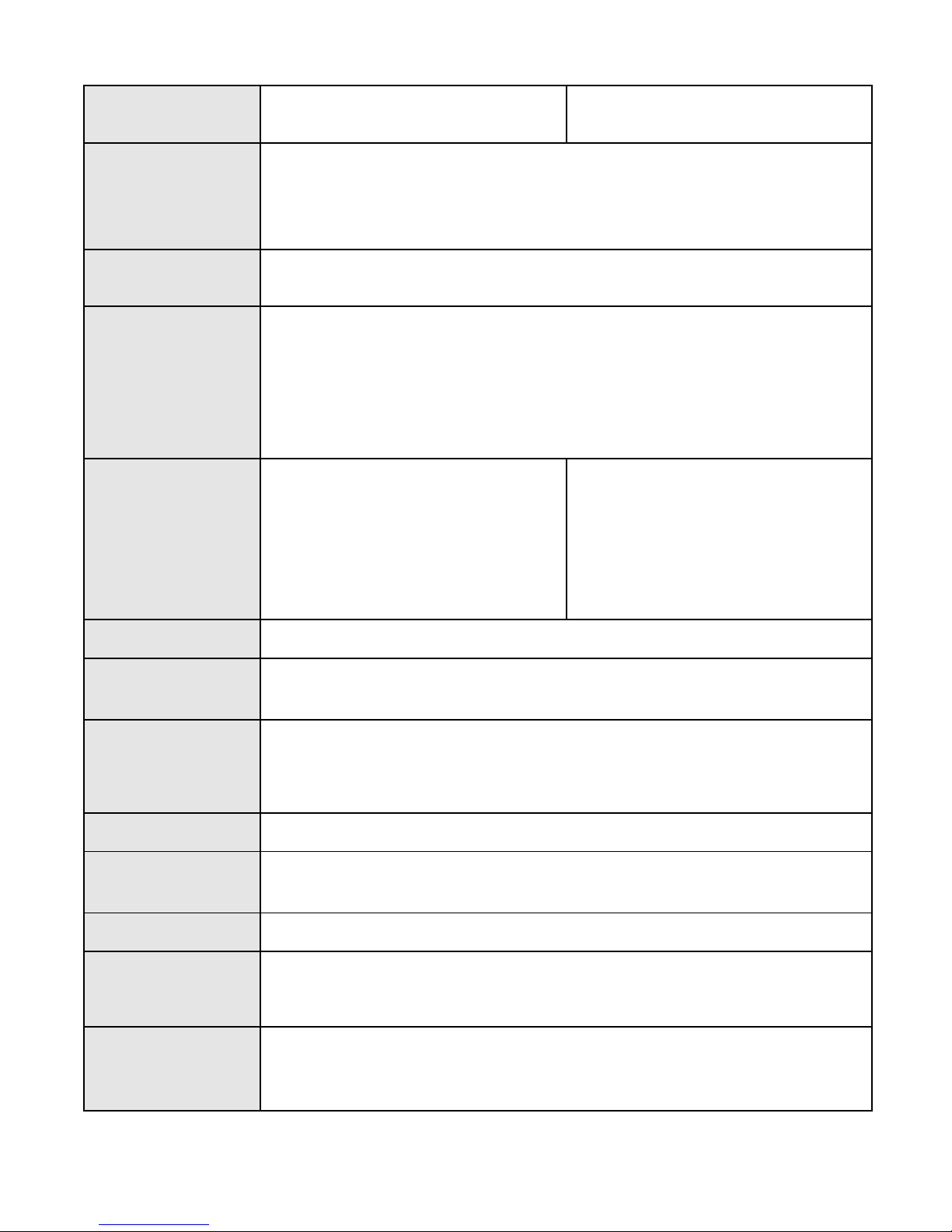
3.2 Dimensions and Weight
Table 3 provides the overall dimensions and weight for the PowerEdge R410 server.
Table 3. R410 Overall Dimensions and Weight
Figure 1 details the dimensions of the PowerEdge R410 server.
Zb goes to the nominal rear wall external surface where the motherboard I/O connectors reside.
Figure 1. R410 Detailed Dimensions
PowerEdge R410 Technical Guide 14
Dell
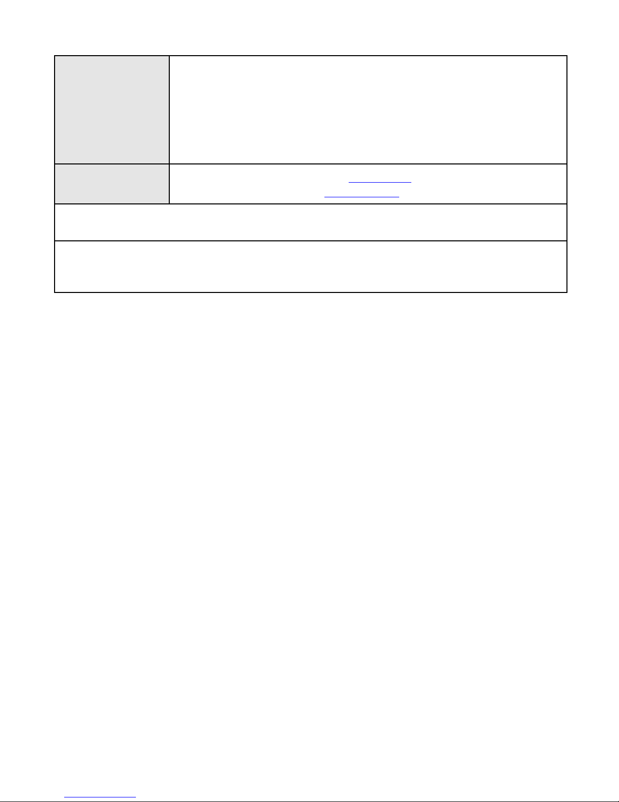
3.3 Front Panel View and Features
The front panel includes the following features:
Front KVM (2x USB, 1x Video)
Diagnostic indicator (quad-pack LED with cabled HDD configuration; 11G LCD with hot-swap
HDD configuration)
System ID button
Power button
HDD activity LED
NMI button
Asset Tag
Detailed views of the front panel are shown in the following figures. For more information, see the
Front-Panel Features and Indicators section in the About Your System Chapter of the PowerEdge R410
Hardware Owner’s Manual on Support.Dell.com.
Figure 2. Front Without Bezel
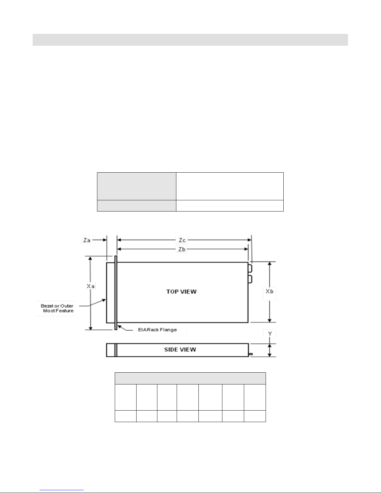
Figure 3. With Bezel View
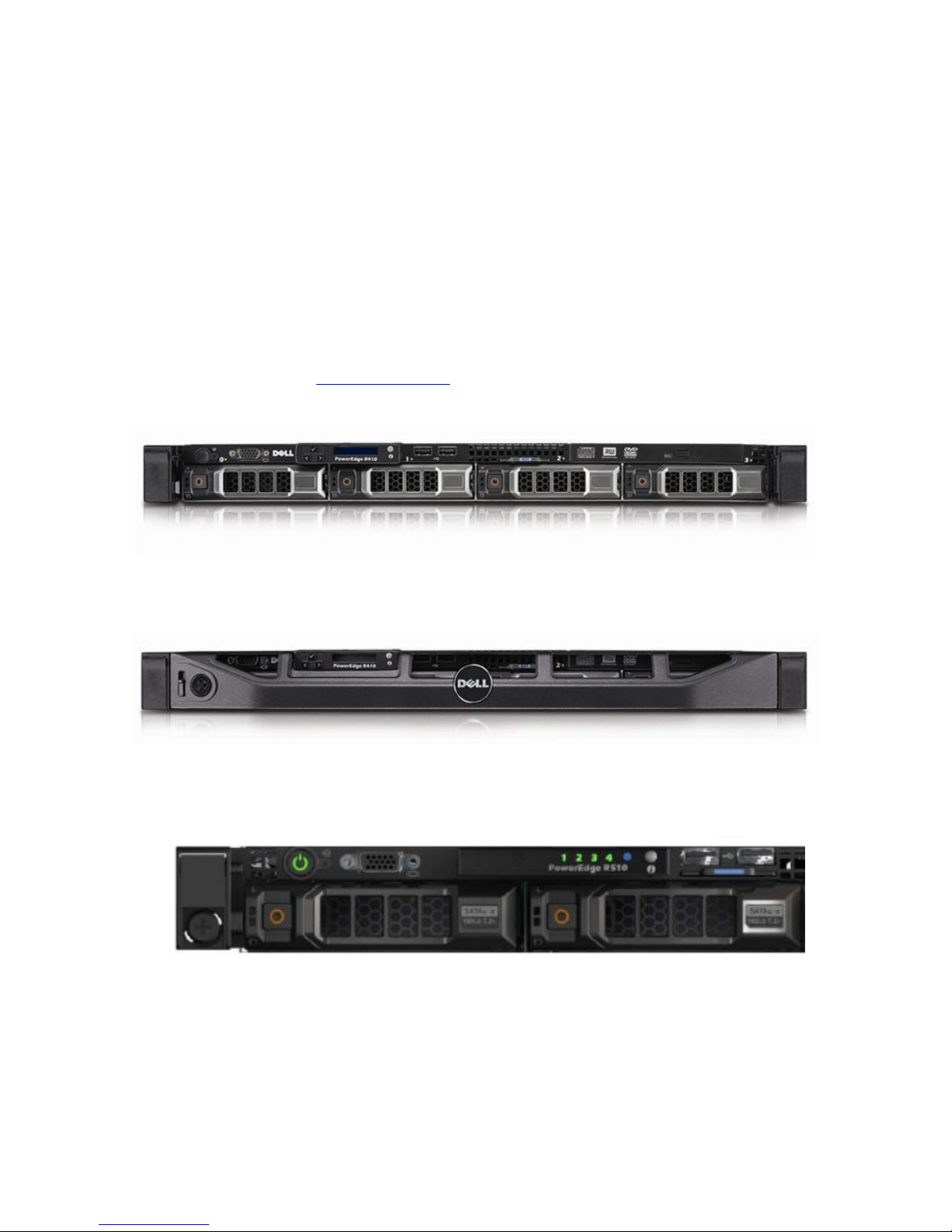
Figure 4. Front Panel Controller
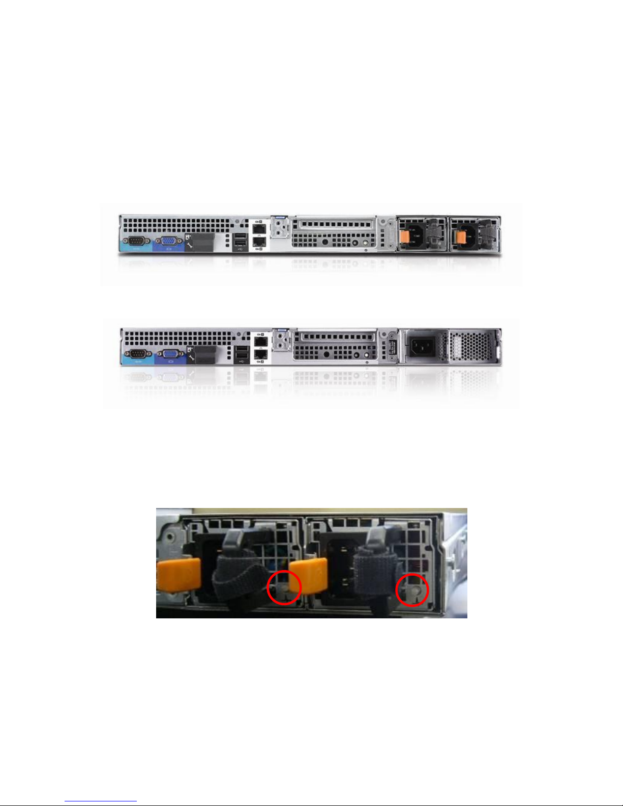
3.4 Back Panel View and Features
Back panel features include:
Active ID CMA Jack
PowerEdge R410 Technical Guide 15
Dell
System ID button
Bi-color system ID LED
(2) Gigabit NIC ports
(2) USB ports
Video
Serial port
RJ45 Connector on iDRAC6 Enterprise (optional)
The following figures show the back panel of the R410 server. For more information, see the BackPanel Features and Indicators in the About Your System Chapter of the PowerEdge R410 Hardware
Owner’s Manual.
Figure 5. With Redundant Power Supply
Figure 6. With Non-redundant Power Supply
3.5 Power Supply Indicators
Figure 7 shows the R410’s redundant Power Supply Unit (PSUs)
Figure 7. Redundant Power Supply Units
Indicator lights show the status of the PSU as follows:
Not lit — AC power is not connected.
Green — In standby mode, a green light indicates a valid AC source is connected to the power supply
and the power supply is operational. When the system is on, a green light also indicates that the
power supply is providing DC power to the system.
PowerEdge R410 Technical Guide 16
Dell
State
Link LED
(Green/Yellow)
Activity LED (Green)
No link
Off
Off
D0uninitalized (out of
box), D3cold, S4
(hibernation)
WOL disabled
Off
Off
WOL enabled, link, no
activity
Green if the port is
operating at maximum
port speed; Yellow
otherwise
Green if the port is
operating at maximum
port speed; Yellow
otherwise
Off
WOL enabled, link,
activity
On (blinking at speed
related to packet
density)
Pre-OS POST or OS
without driver
Link, no activity
Off
Link, activity
On (blinking at speed
related to packet
density)
OS with driver
Link, no activity
Off
Link, activity
On (blinking at speed
related to packet
density)
Amber — Indicates a problem with the power supply.
Alternating green and amber — When hot-adding a power supply, this indicates that the power supply
is mismatched with the other power supply (for example, a High-Output 500W power supply and a
400W power supply are installed in the same system). Capacity of the installed power supplies must
match.
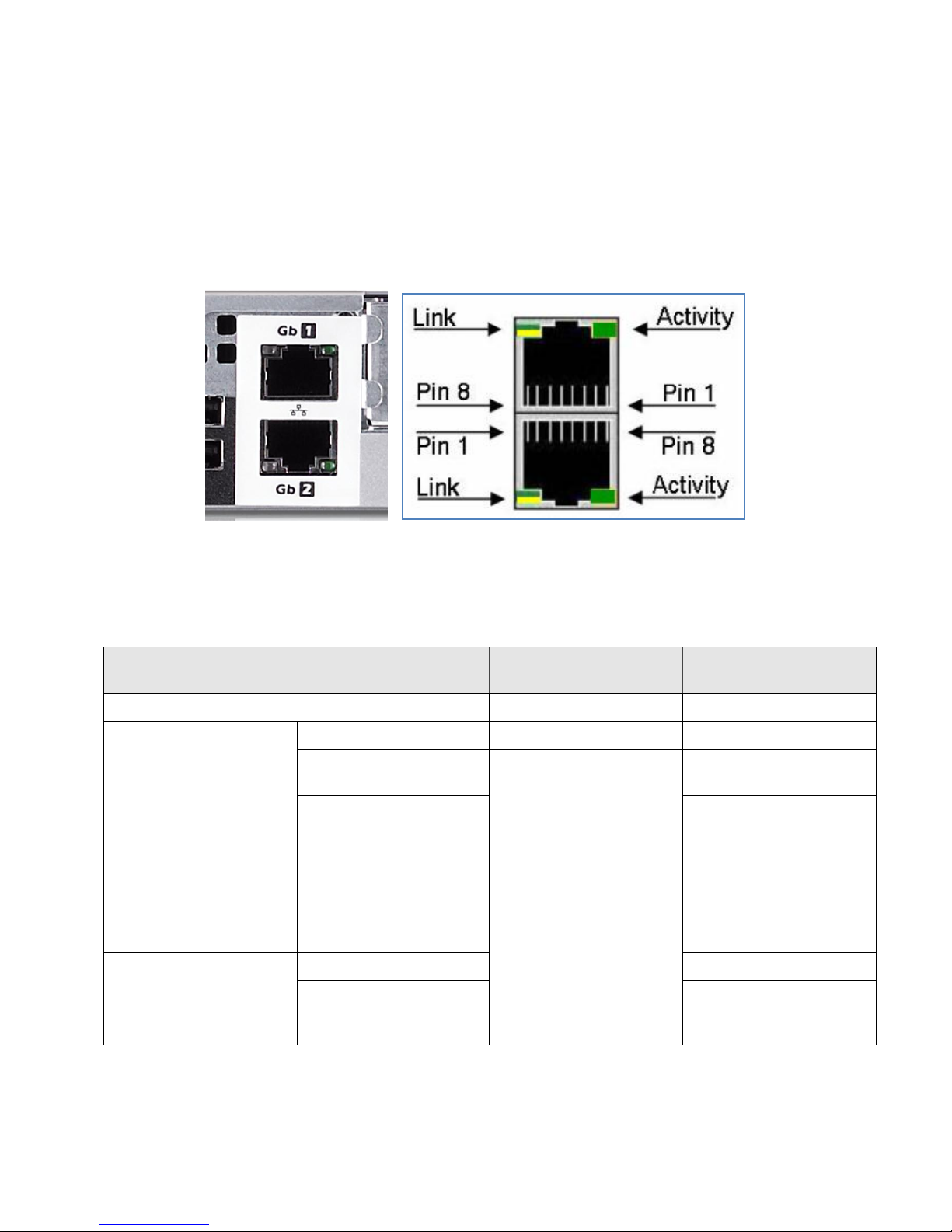
3.6 NIC Indicators
Figure 8 shows the RJ45 connectors.
Figure 8. Dual-Stacked RJ45 Connectors with NIC Indicators
Table 4 details the NIC indicator LED states.
Table 4. NIC Indicator LED States
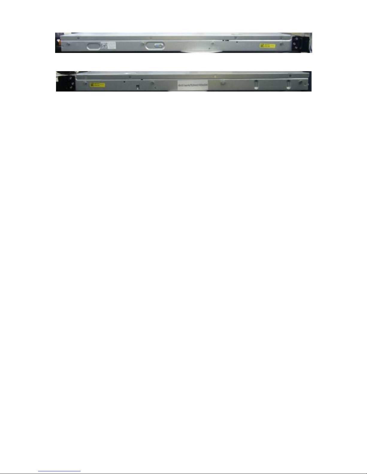
3.7 Side Views
Side views are shown in Figure 9 and Figure 10.
PowerEdge R410 Technical Guide 17
Dell
Figure 9. Left Side View
Figure 10. Right Side View
3.8 Rails and Cable Management
3.8.1 ReadyRails Sliding Rails
ReadyRailsTM Sliding Rails for 4-post racks support includes:
Toolless installation in 19‖ EIA-310-E compliant square or unthreaded round hole 4-post racks
including all generations of Dell racks
Tooled installation in 19‖ EIA-310-E compliant threaded hole 4-post racks (requires the 1U
Threaded Rack Adapter Brackets Kit)
Full extension of the system out of the rack to allow serviceability of key internal components
Optional cable management arm (CMA)
Rail depth and adjustment ranges are as follows:
Rail depth without the CMA: 714 mm
Rail depth with the CMA: 835 mm
Square-hole rack adjustment range: 686-883 mm
Round-hole rack adjustment range: 672-876 mm
Threaded-hole rack adjustment range: 651-897 mm
3.8.2 ReadyRails Static Rails
ReadyRailsTM Static Rails for 4-post & 2-post Racks support:
Toolless installation in 19‖ EIA-310-E compliant square or unthreaded round hole 4-post racks
including all generations of Dell racks
Tooled installation in 19‖ EIA-310-E compliant threaded hole 4-post and 2-post racks
Rail depth and adjustment ranges are as follows:
Rail depth: 622 mm
Square-hole rack adjustment range: 608-879 mm
Round-hole rack adjustment range: 594-872 mm
Threaded-hole rack adjustment range: 604-890 mm
3.9 Fans
There are total of six fans with redundant PSU in the system and four fans with non-redundant PSU.
Figure 11 shows the R410 fans. The four fans at right are the fans for the system, especially for the
CPUs and memories. The two fans at left are there when the system is configured with redundant
PSU. They cool down the redundant PSU.
PowerEdge R410 Technical Guide 18
 Loading...