

Dell External OEMR R310, PowerEdge R310 Technical Manual
PowerEdge R310
Technical Guide
The PowerEdge
R310 is an
enterprise-class
server with the
right balance of
performance and
value.

Dell
This document is for informational purposes only. Dell reserves the right to make changes without
further notice to any products herein. The content provided is as is and without express or implied
warranties of any kind.
Dell, PowerEdge, EqualLogic, PowerVault, OpenManage, and ReadyRails are trademarks of Dell, Inc.
Citrix® and XenServer™ are trademarks of Citrix Systems, Inc. and/or one or more of its subsidiaries,
and may be registered in the United States Patent and Trademark Office and in other countries.
Intel, Xeon, and Speedstep are registered trademarks and MMX, Celeron, and Core are trademarks of
Intel Corporation in the U.S. and other countries. HP and COMPAQ are trademarks of HewlettPackard Company. Broadcom is a registered trademark and NetXtreme is a trademark of Broadcom
Corporation and/or its affiliates in the United States, certain other countries and/or the EU.
CommVault Galaxy® and Simpana® are registered trademarks of CommVault Systems, Inc. InfiniBand
is a registered trademark and service mark of the InfiniBand Trade Association. Matrox is a registered
trademark of Matrox Electronic Systems Ltd. Microsoft, Windows, Windows Server, SQL Server, and
BitLocker, and Hyper-V are either registered trademarks or trademarks of Microsoft Corporation in
the United States and/or other countries. Mellanox is a registered trademark of Mellanox
Technologies, Inc. and ConnectX, InfiniBlast, InfiniBridge, InfiniHost, InfiniRISC, InfiniScale, and
InfiniPCI are trademarks of Mellanox Technologies, Inc. Red Hat is a registered trademark of Red Hat,
Inc. in the United States and other countries. Linux is a registered trademark of Linus Torvalds.
Nuvoton® is a registered trademark of Nuvoton Technology Corporation. Symantec and Backup Exec
are trademarks owned by Symantec Corporation or its affiliates in the U.S. and other countries.
QLogic and PathScale are registered trademarks of Qlogic Corporation. Vizioncore is a trademark of
of Vizioncore Inc. in the United States of America and other countries. VMware is a registered
trademark and vSphere is a trademark of VMware, Inc. in the United States and/or other
jurisdictions. Other trademarks and trade names may be used in this document to refer to either the
entities claiming the marks and names or their products. Dell disclaims proprietary interest in the
marks and names of others.
©Copyright 2010 Dell Inc. All rights reserved. Reproduction or translation of any part of this work
beyond that permitted by U.S. copyright laws without the written permission of Dell Inc. is unlawful
and strictly forbidden.
Initial Release July 2010
Dell PowerEdge R310 Technical Guide 1

Dell
Table of Contents
1 Product Description ............................................................................................ 7
1.1 Overview .................................................................................................. 7
1.1.1 Business Value ...................................................................................... 7
1.1.2 Easy to Manage ..................................................................................... 7
1.1.3 Easy to Set Up ...................................................................................... 7
1.2 Product Comparison ..................................................................................... 8
2 New Technologies ............................................................................................ 11
2.1 Overview ................................................................................................ 11
2.2 Detailed Information .................................................................................. 11
3 System Overview ............................................................................................. 12
4 Mechanical .................................................................................................... 15
4.1 Chassis Description..................................................................................... 15
4.2 Dimensions and Weight ................................................................................ 15
4.3 Front Panel View and Features ...................................................................... 15
4.4 Front View Cabled and Hot-Swap HDD Configurations ............................................ 16
4.5 Back Panel View and Features ....................................................................... 17
4.6 Power Supply Indicators ............................................................................... 17
4.7 NIC Indicators ........................................................................................... 18
4.8 Side Views and Features .............................................................................. 19
4.9 Internal Chassis Views ................................................................................. 20
4.10 Rails and Cable Management ......................................................................... 21
4.11 Fans ...................................................................................................... 22
4.12 Cabling ................................................................................................... 23
4.13 Control Panel LED & LCD .............................................................................. 24
4.14 LED Status Description ................................................................................ 24
4.15 R310 LCD (Optional) Configuration .................................................................. 24
5 Security ........................................................................................................ 26
5.1.1 Cover Latch ....................................................................................... 26
5.1.2 Bezel ............................................................................................... 26
5.1.3 Hard Drive ......................................................................................... 26
5.1.4 Trusted Platform Module (TPM) ................................................................ 26
5.1.5 Power Off Security ............................................................................... 26
5.1.6 Intrusion Alert .................................................................................... 26
5.1.7 Secure Mode ...................................................................................... 26
5.2 Battery ................................................................................................... 27
5.3 Field Replaceable Units (FRU)........................................................................ 27
5.4 User Accessible Jumpers, Sockets, and Connectors ............................................... 27
6 Power, Thermal, Acoustic .................................................................................. 28
6.1 Power Supplies ......................................................................................... 28
6.1.1 Power Supply Specifications .................................................................... 28
6.1.2 Power Supply Connectors ....................................................................... 28
6.2 Environmental Specifications......................................................................... 29
Dell PowerEdge R310 Technical Guide 2

Dell
6.3 Energy Star Compliance ............................................................................... 30
6.4 Acoustics ................................................................................................ 30
7 Processors ..................................................................................................... 32
7.1 Overview ................................................................................................ 32
7.2 Supported Processors .................................................................................. 33
7.3 Processor Configurations .............................................................................. 33
8 Memory ........................................................................................................ 35
8.1 Overview ................................................................................................ 35
8.1.1 UDIMM .............................................................................................. 35
8.1.2 RDIMM .............................................................................................. 36
8.2 Slots/Risers ............................................................................................. 37
8.3 Speed .................................................................................................... 37
8.4 Sparing ................................................................................................... 38
8.5 Mirroring ................................................................................................. 38
8.6 RAID ...................................................................................................... 38
9 Chipset ........................................................................................................ 40
9.1 Overview ................................................................................................ 40
9.2 Direct Media Interface (DMI) ......................................................................... 40
9.3 PCI Express Interface .................................................................................. 40
9.4 SATA Interface .......................................................................................... 40
9.5 AHCI ...................................................................................................... 40
9.6 Intel Rapid Storage Technology ...................................................................... 40
9.7 PCI Interface ............................................................................................ 41
9.8 Low Pin Count Interface (LPC) ....................................................................... 41
9.9 Serial Peripheral Interface (SPI) ..................................................................... 41
9.10 Compatibility Module (MDA Controller, Timer/Counters, Interrupt Controller) .............. 41
9.11 Advanced Programmable Interrupt Controller (APIC) ............................................. 41
9.12 Universal Serial Bus (USB) Controllers .............................................................. 41
9.13 Real-Time Clock (RTC) ................................................................................ 42
9.14 General Purpose Inputs and Outputs (GPIO) ....................................................... 42
9.15 Enhanced Power Management........................................................................ 42
9.16 Manageability ........................................................................................... 42
9.17 System Management Bus (SMBus 2.0) ............................................................... 43
9.18 Intel Anti-Theft Technology .......................................................................... 43
9.19 Intel Virtualization Technology for Directed I/O .................................................. 43
9.20 JTAG Boundary-Scan ................................................................................... 43
10 BIOS ............................................................................................................ 44
10.1 Overview ................................................................................................ 44
10.2 Supported ACPI States ................................................................................. 44
10.3 Power Management Modes ............................................................................ 45
10.3.1 Dell Active Power Controller ................................................................... 45
10.3.2 Power-Saving BIOS Setting (OS Control) ...................................................... 45
10.3.3 Maximum Performance .......................................................................... 45
11 Embedded NICs/LAN on Motherboard (LOM) ............................................................. 48
11.1 Overview ................................................................................................ 48
11.2 Multiple Speed Support................................................................................ 48
11.3 PCI Express Compliance ............................................................................... 48
11.4 Diagnostics .............................................................................................. 48
Dell PowerEdge R310 Technical Guide 3

Dell
11.5 Power Management .................................................................................... 48
11.6 Setting Power Management Options ................................................................. 48
11.7 Broadcom Advanced Control Suite 3 ................................................................ 49
11.8 Teaming ................................................................................................. 49
11.9 VLAN ..................................................................................................... 51
11.10 Preboot Environment .................................................................................. 52
11.11 iSCSI Boot ............................................................................................... 52
11.12 Diagnostic Tests ........................................................................................ 53
11.13 Flow Control ............................................................................................ 53
11.14 Network Controller Sideband Interface (NC-SI) .................................................... 53
11.15 IPv4 and IPv6 Checksum Offload ..................................................................... 53
11.16 IPv4 and IPv6 Large Send Offload .................................................................... 54
11.17 Jumbo MTU .............................................................................................. 54
11.18 LSO and Jumbo Frames ................................................................................ 54
11.19 Wake-Up Capabilities .................................................................................. 54
11.20 WOL Settings ............................................................................................ 54
11.21 Virtualization Functionality .......................................................................... 54
11.22 Usage of Multiple Queues ............................................................................. 55
11.23 LOM Performance ...................................................................................... 55
12 I/O Slots ....................................................................................................... 57
12.1 Overview ................................................................................................ 57
12.2 Quantities and Priorities .............................................................................. 57
12.3 Boot Order .............................................................................................. 58
12.4 External Controller Cards ............................................................................. 58
12.5 PCI Card Dimensions ................................................................................... 58
13 Storage ........................................................................................................ 59
13.1 Overview ................................................................................................ 59
13.2 Drives .................................................................................................... 60
13.3 RAID Configurations .................................................................................... 60
13.4 LED Indicators .......................................................................................... 61
13.5 Optical Drives ........................................................................................... 61
13.6 Tape Drives ............................................................................................. 62
14 Video and Audio .............................................................................................. 63
14.1 Video ..................................................................................................... 63
14.2 Audio ..................................................................................................... 63
15 Rack Information ............................................................................................. 64
15.1 Overview ................................................................................................ 64
15.2 Rails ...................................................................................................... 64
15.3 Cable Management Arm (CMA) ....................................................................... 66
15.4 Rack View ............................................................................................... 67
16 Operating Systems ........................................................................................... 68
17 Solutions ....................................................................................................... 69
17.1 Virtualization ........................................................................................... 69
17.2 Database ................................................................................................ 69
18 Systems Management ........................................................................................ 70
18.1 Overview ................................................................................................ 70
18.2 Server Management .................................................................................... 70
18.3 Embedded Server Management ...................................................................... 71
18.4 Lifecycle Controller and Unified Server Configurator ............................................ 71
18.5 iDRAC6 Express ......................................................................................... 72
Dell PowerEdge R310 Technical Guide 4

Dell
18.6 iDRAC6 Enterprise ...................................................................................... 72
19 Persistent Storage ........................................................................................... 75
19.1 Overview ................................................................................................ 75
19.2 Internal SD Module (Unmanaged Internal Persistent Storage) ................................... 75
19.3 Managed iDRAC6 Express and iDRAC6 Enterprise .................................................. 75
20 Peripherals .................................................................................................... 76
20.1 USB peripherals ......................................................................................... 76
20.2 External Storage ........................................................................................ 76
21 Packaging Options ........................................................................................... 78
Tables
Table 1. Comparison Table ..................................................................................... 8
Table 2. Product Features Summary ........................................................................ 12
Table 3. NIC Indicator Codes ................................................................................. 19
Table 4. Environmental Requirements ...................................................................... 29
Table 5. Acoustical Information ............................................................................. 30
Table 6. Supported Processors ............................................................................... 33
Table 7. DIMMs Supported .................................................................................... 35
Table 8. UDIMM Support ...................................................................................... 36
Table 9. RDIMM Support ....................................................................................... 36
Table 10. Memory Population ................................................................................. 38
Table 11. Supported Configurations .......................................................................... 39
Table 12. Supported ACPI States .............................................................................. 45
Table 13. Power Management Features on the R310 ....................................................... 46
Table 14. Current Power Profiles ............................................................................. 47
Table 15. Smart Load Balancing ............................................................................... 50
Table 16. Teaming Types and Detail ......................................................................... 50
Table 17. Broadcom Teaming Software Component ....................................................... 51
Table 18. LOM Performance ................................................................................... 56
Table 19. PCIe Slot Specification ............................................................................. 57
Table 20. I/O Slots Quantities and Priorities ................................................................ 57
Table 21. External Controller Cards .......................................................................... 58
Table 22. Add-in Card Sizes .................................................................................... 58
Table 23. RAID Configurations ................................................................................. 60
Table 24. Rail Information ..................................................................................... 66
Table 25. Unified Server Configurator Features and Description......................................... 72
Table 26. Features List for BMC, iDRAC6, and vFlash ...................................................... 73
Table 27. External Storage ..................................................................................... 76
Table 28. R310 Volatility ....................................................................................... 80
Dell PowerEdge R310 Technical Guide 5

Dell
Figures
Figure 1. Chassis Dimensions .................................................................................. 15
Figure 2. Front View Cabled HDD Configuration—With LED .............................................. 16
Figure 3. Front View Hot-swap HDD Configuration with LCD Panel ..................................... 16
Figure 4. Back Panel View ..................................................................................... 17
Figure 5. For Non-Redundant PSU ............................................................................ 18
Figure 6. For Redundant PSU .................................................................................. 18
Figure 7. NIC Indicators ........................................................................................ 19
Figure 8. Right Side ............................................................................................ 19
Figure 9. Left Side .............................................................................................. 19
Figure 10. Cable HDD Chassis with Single PSU ............................................................ 20
Figure 11. Hot Plug HDD Chassis with Redundant PSU ................................................... 21
Figure 12. Non-Redundant PSU Fan Configuration (3 Fans) ............................................. 22
Figure 13. Redundant PSU Fan Configuration (5 Fans) ................................................... 23
Figure 14. LED Control Panel ................................................................................ 24
Figure 15. System Control Panel ............................................................................ 24
Figure 16. Intrusion Detection Switch ...................................................................... 26
Figure 17. Battery ............................................................................................. 27
Figure 18. PERC Battery ...................................................................................... 27
Figure 19. Power Input Connectors ......................................................................... 29
Figure 20. Processor Location ............................................................................... 34
Figure 21. BCM5716C LOM‘s Multiple Queues in Virtual Environment ................................. 55
Figure 22. Broadcom LOM .................................................................................... 56
Figure 23. Cabled Hard Drive Chassis ...................................................................... 59
Figure 24. Hot-Swap Hard Drive Chassis ................................................................... 59
Figure 25. Backplane with Hot-Swap Option .............................................................. 59
Figure 26. Hard Drives ........................................................................................ 60
Figure 27. R310 Sliding Rails with Optional CMA ......................................................... 64
Figure 28. 1U Threaded Rack Adapter Brackets Kit ...................................................... 65
Figure 29. R310 Static Rails .................................................................................. 65
Figure 30. Rail Adjustability ................................................................................. 66
Figure 31. R310 Mounted in the A3 Sliding Rails with the CMA ......................................... 67
Figure 32. R310 Mounted in the A4 Static Rails in 2-post Center Mount Configuration ............. 67
Figure 33. Persistent Storage Options ...................................................................... 75
Dell PowerEdge R310 Technical Guide 6

Dell
1 Product Description
1.1 Overview
The Dell™ PowerEdge™ R310 is a high-performance, 1-socket 1U rack server with flexible computing power,
business scalability, simplified management, data protection, and security options.
Dell PowerEdge 11th generation servers are designed to meet customer needs by combining customerinspired design with excellent reliability, security, and commonality. The PowerEdge R310 embodies the
Dell 11G design principles with the same system design commonality, reliability, energy efficiency and
simplified systems management features true to the entire portfolio. The result is a compact, efficient
server that helps customers of all sizes lower IT-related costs, reduce complexity, and free up resources.
The Dell PowerEdge R310 provides the flexible computing power, business scalability, simplified
management, data protection, and security options to make it an ideal choice for small to midsize
businesses, remote offices, and enterprises.
The Dell PowerEdge R310 offers:
Business Value: The performance, security options, and availability scale to meet a variety of
business needs.
Simplified Management: With optional Dell Lifecycle Controller and optional full OpenManage™ suite
designed for improved diagnostics and reduced operational costs.
Flexible Technology: Energy-efficient, compact server for ease of deployment.
1.1.1 Business Value
The PowerEdge R310 rack server offers the right balance of performance, enterprise-class options, and
business value to meet the needs of small to midsized businesses, branch offices and enterprises alike with:
Price for performance that includes options for full redundancy in power supplies and hot-swap hard
drives.
Processor options and memory configurations that are balanced to run typical business applications
such as Microsoft® Windows® Small Business Server, Business Center Essentials, SQL Server®
Workgroup/Standard, Active Directory®, and SharePoint® as well as Oracle® 11g Standard, VMware®,
and file/print.
Multiple RAID options and up to four 2.5 or 3.5 inch hard drives to help keep your data safe.
1.1.2 Easy to Manage
The PowerEdge R310 lets you devote more focus to running your business. The optional advanced embedded
management engine, Lifecycle Controller, automates common management tasks and enables zero-media,
low-touch deployment that is efficient, secure, and user-friendly.
Dell Lifecycle Controller simplifies administrator tasks by performing a complete set of provisioning
functions such as system deployment, system updates, hardware configuration and diagnostics from a single
intuitive interface called Unified Server Configurator in a pre-OS environment. This eliminates the need to
use and maintain multiple pieces of disparate CD/DVD media. With Dell Lifecycle Controller server
deployment automation, the R310 can be up and running fast.
Also part of the Dell OpenManage portfolio is the Dell Management Console, which is included with every
Dell server and provides IT administrators with a consolidated console view of their IT infrastructure.
1.1.3 Easy to Set Up
The PowerEdge R310 features a compact chassis that allows flexibility for rack-oriented deployments. The
optional advanced systems management capabilities of Dell Lifecycle Controller along with an interactive
Dell PowerEdge R310 Technical Guide 7

Dell
Feature/Spec
R310
R300 (Predecessor)
R410 (Next level up)
Socket
Single, LGA1156
Single, LGA771
Double, LGA1366
Processor
Quad-Core Intel® Xeon®
processors 3400 series
Intel® Core™ i3-540
Intel® Core™ i3-530
Intel® Pentium® G6950
Intel® Celeron® G1101
Quad-Core Intel® Xeon®
Processor 5000 series
Dual and Quad-Core Intel®
Xeon® Processor 3000 series
Intel® Core 2 Duo® processor
Intel® Celeron® processor
2S Intel® Xeon® processor 5500
series
Data Rate
DMI @2.5 GT/s (for 4 lanes,
bandwidth 2GB/s)
DMI: CPU to PCH
1333MHz (bandwidth 10.4
GB/s)
FSB: CPU to north bridge
QPI @ 6.4 GT/s (for 20
lanes, bandwidth 25.6 GB/s)
QPI: CPU to IOH
# Processors
1 1 1 to 2
# Cores
Intel® Xeon®: Quad
DT proc: Dual
Dual or Quad
Dual or Quad
L2/L3 Cache
Intel® Xeon®: 8MB
DT proc: 4, 3 or 2M
Intel® Celeron®: 512 MB L2
Intel® Core™ 2 Duo: 2MB L2
Intel® Xeon® 3000 Series: 6MB
L2
Intel® Xeon® 5000 Series: 6MB
L2
4MB or 8MB
Chipset
Intel® 3420
Intel® 3400
Intel® 5520
DIMMs
DDR3
6 R-DIMMs or
4 U-DIMMs
DDR II
6 R-DIMMs
4+4 DDR3
Unbuffered w/ECC or
Registered w/ECC
1333/1066/800MHz
DIMM Speed
1333/1066MHz
667MHz
1333/1066/800MHz
Minimum/Maximum
RAM
1GB/32GB
512MB/24GB
1GB/64GB
HD Bays
4 x 3.5‖
Optional hot-swap
Or 2.5‖ SAS/ SSD via hot-
swap chassis
2 x 3.5‖
Cabled or hot-swap hard
drive bays
4x 3.5‖
Optional hot-swap
Support 2.5" HDDs via hot-swap
tray
HD Types
SATA/SAS/SSD
SATA/SAS
Default SATA. Optional SAS and
SSD via add-in controller
External Drive
Bay(s)
1 for slim ODD
1 for slim ODD
1 for slim ODD
LCD help simplify server set-up and maintenance. It is an ideal rack for small businesses and larger offices
needing manageability.
The PowerEdge R310 is an enterprise-class server with the right balance of performance and value.
1.2 Product Comparison
Table 1. Comparison Table
Dell PowerEdge R310 Technical Guide 8

Dell
Feature/Spec
R310
R300 (Predecessor)
R410 (Next level up)
Internal HD
Controller
Intel® 3420
PERC S100 (Embedded SW
RAID)
ICH9R
Chipset-based SATA
Optional HD
Controller
NON-RAID:
SAS 5/E (Field Support Only –
No Factory Install)
LSI2032 (For TBU)
6Gb/s SAS HBA
RAID:
PERC6/E (Field Support Only)
SAS 5/E (Field Support Only)
SAS 6/iR
PERC S300
H200
H700
H800
NON-RAID:
SAS 5/E
LSI2032 (For TBU)
RAID:
SAS 5/E
SAS 6/iR
PERC 6/i
PERC 6/E
NON-RAID:
SAS 5/E
LSI 2032 (For TBU only)
SAS 6/E
RAID:
SAS 6/iR
PERC 6/i
PERC 6/E
Availability
ECC Memory, Hot-swap HDD;
Redundant PSU; Quad-pack
LED diagnostic/LCD with Hotswap HDD chassis, TPM
ECC memory, Add-in RAID,
tool-less chassis, Hot-plug
HDD, Redundant PSU,
TPM/CTPM
Hot-swap HDD; Redundant PSU;
Quad-pack LED diagnostic/LCD
with Hot-swap HDD chassis;
Memory mirroring
Server
Management
BMC, IPMI 2.0 compliant; Full
Open Manage suite
Optional; iDRAC6 Express,
iDRAC6 Enterprise, Vflash
Full OpenManage™ suite
Optional DRAC5
BMC, IPMI 2.0 compliant; Full
Open Manage suite
Optional; iDRAC6 Express,
iDRAC6 Enterprise, Vflash
I/O Slots
Riser 1: PCIe x16 (x8
routing), Full Height/ Half
Length, Gen 2
Riser 2: PCIe x8 (x8 routing),
Full Height/Half Length, Gen
2
(embedded): PCIe x8 (x4
routing)
Riser 1: Two PCIe x8
Riser 2: One PCI-X 64/133
and one PCIe x8
One PCIe x16 (True x16, Gen2);
full height, half length
RAID
PERC S100: RAID 0, 1, 5, 10
(SATA only)
PERC S300: RAID 5, 10 (SATA
& SAS)
SAS 6i/R: RAID 0, 1 (SATA &
SAS)
PERC H200: RAID 0, 1, 10
(SATA, SAS & SSD)
PERC H700: RAID 0, 1, 5, 6,
10 (SATA, SAS & SSD)
PERC H800: RAID 0, 1, 5, 6,
0,1, 5, 6, 10
See optional Storage Controller
Dell PowerEdge R310 Technical Guide 9

Dell
Feature/Spec
R310
R300 (Predecessor)
R410 (Next level up)
10 (SATA, SAS & SSD)
NIC/LOM
2x GbE LOM
2x GbE LOM
2x GbE LOM
Optional: various NIC available
USB
2 rear/2 front/2 internal
2 rear/2 front/1 internal
2 front/2 rear/2 internal
Power Supplies
Non-Redundant, 350W (80+
Bronze)
Optional Redundant, 400W
(80+ Silver)
Auto Ranging (100V~240V)
Single power supply (400W)
Optional redundant power
supplies (400W each)
Non-Redundant, 480W (80+
SILVER)
Optional Redundant,
500W (80+ GOLD)
Auto Ranging (100V~240V)
Fan
Non-redundant, non-hotswappable
Non-redundant, non-hotswappable
Non-redundant, non-hotswappable
Chassis
Rack
Rack
Rack
Dimension
(HxWxD)
42.4 x 434.0 x 610 (mm)
( w/o bezel)
1.67 x 17.10 x 24.00 (in)
42.35 x 426.3 x 660.4 (mm)
(w/o bezel)
1.67 x 16.78 x 26 (in)
43.0 x 434.0 x 627.1 (mm)
(w/o ear, w/o bezel)
1.69 x 17.09 x 24.69 (in)
Weight
Max: 33.02 lbs (15Kg)
Max: 29.66 lbs (13.45Kg)
Max: 62.61lbs (28.4Kg)
Dell PowerEdge R310 Technical Guide 10

Dell
2 New Technologies
2.1 Overview
New Intel 1 Socket platform: Intel Xeon processor 3400 series with Intel 3420 chipset
SSD advantage (support SSD drives)
Self Encrypting Drives (SED)
Software RAID PERC S100 & PERC S300
6Gb/s SAS HBA
PERC7 support including: PERC H200, H700, H800
Next generation Dell embedded server management
o iDRAC express with Lifecycle Controller and Unified Server Configurator
o Optional iDRAC enterprise—Optional vFlash
DDR3 memory technology which replaces fully buffered DIMMs in the new Intel architecture (Native
DDR3 memory capability improves memory access speed, lowers latency and allows more memory
capacity (up to 6 DIMMs per 1 socket platform).)
2.2 Detailed Information
Platform Features:
Highly integrated single-processor solution
Processors:
Intel Xeon processor 3400 series with Intel 3420 chipset
Socket: LGA1156
Intel
Intel
8MB of Intel
®
Turbo Boost Technology for dynamic frequency scaling
®
Hyper-Threading technology for 8-thread processing with quad core performance
®
Smart Cache (Xeon)
Integrated memory controller (IMC)
o DDR 3 1066/1333 UDIMM, 1066/1333 RDIMM (Xeon only)
o Support 2 channels DDR3
o Up to 2 UDIMMs or 3 RDIMMs per channel
o 16GB UDIMMs and 32GB max with RDIMMs
o Up to 4 U-DIMMs, up to 1333 MHz
o Up to 6 R-DIMMs, up to 1333 MHz (6 DIMMs at 800 MHz)
Software RAID: Dell Software RAID is a chipset RAID enhanced version developed based on Intel chipset 3420.
PERC S100 is purely a firmware/driver upgrade from Intel chipset. PERC S300, in addition to chipset
firmware/driver upgrade, has a controller on the add-in PCIe adapter card.
PERC S100 and S300 support Microsoft® operating systems only (no Linux® OS or virtualization solutions).
Dell PowerEdge R310 Technical Guide 11

Dell
Feature
Technical Specifications
Form Factor
1-Socket 1U Rack
Processors
Quad-Core Intel® Xeon® processors 3400 series
Intel® Core™ i3 processors
Intel® Pentium® G6950
Intel® Celeron® G1101
Processor Sockets
1
Cache
2, 3, 4 and 8MB
Chipset
Intel® 3420 Chipset
Memory1
Up to 32GB (6 DIMM slots) 1GB/2GB/4GB/8GB 1066 & 1333MHz
I/O Slots
2 PCIe G2 slots:
Slot 1: PCIe x16 (x8 routing), Full Height/Half Length
Slot 2: PCIe x8 (x8 routing), Full Height /Half Length
RAID Controller
Internal Controllers:
6Gb/s SAS HBA
PERC H200 (6Gb/s)
PERC H700 (6Gb/s) with 512MB battery-backed cache; 512MB, 1GB
Non-Volatile battery-backed cache
SAS 6/iR
PERC S100 (software based)
PERC S300 (software based)
Drive Bays
Cabled or hot-swap options available:
4 hard drive chassis: 3.5‖ SAS and SATA or 2.5‖ SAS and SSD drives
Maximum Internal
Storage
Currently up to 8TB; increased to 12TB by end of 2010
3 System Overview
R310 is a 1S rack product designed to deliver value with flexible options allowing performance and
redundancy for small businesses and scaling to the enterprise. The R310 is an ideal for small business and
enterprise customers and offers features such as:
Feature configurability
Server management option with iDRAC features to help simplify your IT
Security features with TPM, internal USB and IPv6
Competitive storage expandability and $/GB with 4 x 3.5‖ HDD, both cabled and hot swap
Serviceability and diagnostics with optional interactive LCD
Compact chassis depth of 24‖ (61 cm) to address space constraints including closets, shallow racks,
mobile server enclosures, wall server enclosures, A/V racks and legacy server racks
Table 2. Product Features Summary
Dell PowerEdge R310 Technical Guide 12

Dell
Feature
Technical Specifications
Hard Drives1
3.5‖ cabled SATA (7.2K RPM): 160GB, 250GB, 500GB, 1000GB, 2000GB
3.5‖ cabled Near Line SAS (7.2K RPM): 500GB, 1000GB, 2000GB
3.5‖ hot-swap SAS (15K RPM): 146GB, 300GB, 450GB, 600GB, (10K
RPM) 600GB
3.5‖ hot swap SAS (10K RPM) 600GB
3.5‖ 6Gps SAS (7.2K): 2TB
2.5‖ hot-swap SAS (10K RPM): 146GB, 300GB
2.5‖ hot-swap SSD 50GB, 100GB
Communications
Intel® Gigabit ET Quad Port Server Adapter
Intel® Gigabit ET Dual Port Server Adapter
Broadcom® NetExtreme™ II 5709 Dual-Port Gb Ethernet TOE Server
Adapter
Broadcom® NetExtreme™ II 5709 Dual-Port Gb Ethernet TOE/iSCSI
Offload Server Adapter
Intel® PRO/1000 PT Server Adapter
Brocade® CNA Dual-port adapter
Optional Add-In HBAs:
Brocade® FC4 and 8 GB HBAs
Power Supply
One non-redundant 350W power supply
Two hot-pluggable redundant 400W hot-plug power supplies
Availability
Hot-plug hard drives, hot-plug redundant power supplies, DDR3 ECC
memory, and quad-pack LED or an interactive LCD display screen
Video
Matrox® G200eW w/ 8MB
Remote Management
Optional iDRAC Express, iDRAC 6 Enterprise
Systems Management
Full OpenManage™ Support:
BMC, IPMI2.0 compliant
Lifecycle Controller enabled via optional: iDRAC6 Express, iDRAC6
Enterprise and vFlash
Rack Support
ReadyRails™ sliding rails with optional cable management arm for 4post racks (optional adapter brackets required for threaded hole
racks); ReadyRails™ static rails for 2-post and 4-post racks
Operating Systems
Microsoft® Windows® Essential Business Server 2008
Microsoft® Windows Server® 2008 SP2, x86/x64 (x64 includes Hyper-
V™)
Microsoft® Windows Server® 2008 R2, x64 (includes Hyper-V™ v2)
Microsoft® Windows® HPC Server 2008
Novell® SUSE® Linux® Enterprise Server
Red Hat® Enterprise Linux®
Solaris™ 10 05/10 (update 10) x86-64
Virtualization OS Options:
Dell PowerEdge R310 Technical Guide 13
Dell
Feature
Technical Specifications
Citrix® XenServer™ Enterprise 5.6 x86-64
Microsoft® Hyper-V™ via Microsoft® Windows Server® 2008
VMware® vSphere™ 4.1 (including VMware ESX® 4.1 or VMware ESXi™
4.1)
Vizioncore™ vEssentials
Novell® PlateSpin® Migrate
For more information on the specific versions and additions, visit
www.dell.com/OSsupport.
Featured Database
Applications
Microsoft® SQL Server® solutions (see Dell.com/SQL)
Oracle® database solutions (see Dell.com/Oracle)
1 GB means 1 billion bytes and TB equals 1 trillion bytes; actual capacity varies with preloaded
material and operating environment and will be less.
Dell PowerEdge R310 Technical Guide 14
Dell
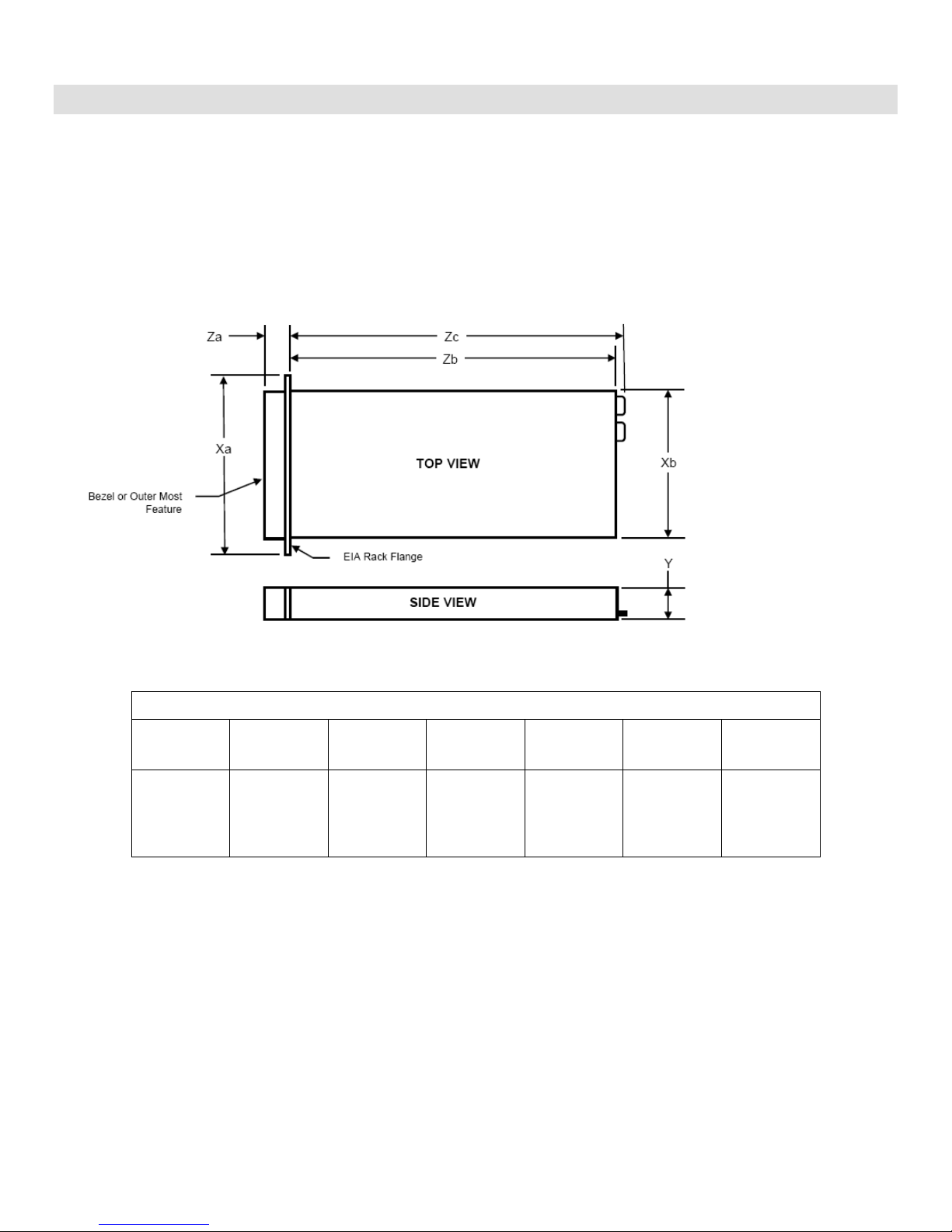
Chassis Dimensions
Xa
Xb (Width)
Y (Height)
Za
w/ bezel
Za
w/o bezel
Zb (Depth)
Zc
482.4
434 mm
(17.09
inch)
42.4 mm
(1.69 inch)
35.0
21.0
612.6 mm
(24.12
inch)
641.9
4 Mechanical
4.1 Chassis Description
The R310 is a 1U /1 Socket rack mount chassis. The updated design includes a new LCD (Optional), bezel
and hard-drive carriers. Additional changes include tool-less rack latches, a pull out tray for customer
labels, supports persistent storage with internal USB and SD card slot and updated power supplies.
4.2 Dimensions and Weight
Figure 1. Chassis Dimensions
Weight: 15.0 Kg (33.02 lb) (maximum configuration)
4.3 Front Panel View and Features
Front I/O panel access including USB and VGA interfaces. The following components are located on the
front:
System Identification panel (Information tag): A slide-out panel for system identification labels
including the Express Service tag, embedded NIC MAC address and iDRAC6 Enterprise card MAC
address. Space has been provided for an additional label
Dell PowerEdge R310 Technical Guide 15
Dell
Power on indicator, power button
NMI button (Non-maskable interrupt): A device sends an NMI to signal the processor about hardware
errors; it is used to troubleshoot software and device driver errors when using certain operating
system
(2) USB connectors: Connects USB devices to the system. The ports are USB2.0 compliant
Video connector
LED menu buttons: Allows you to navigate the control panel LED menu
Optional LCD panel: Provides system ID, status information, and system error messages
System identification button
Optical drive (optional)
Hard drives
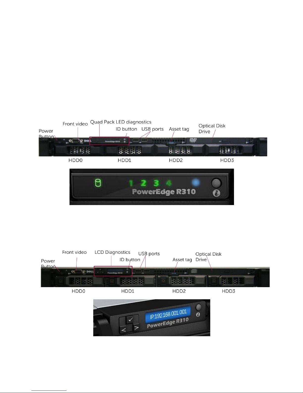
4.4 Front View Cabled and Hot-Swap HDD Configurations
Figure 2. Front View Cabled HDD Configuration—With LED
Figure 3. Front View Hot-swap HDD Configuration with LCD Panel
Dell PowerEdge R310 Technical Guide 16
Dell
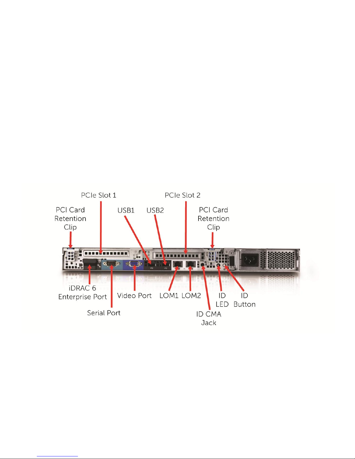
4.5 Back Panel View and Features
The following components are located on the rear panel of the R610 enclosure:
(1) 15-pin VGA connector
(1) 9-pin serial port connector
(2) Integrated 10/100/1000 Ethernet RJ-45 connectors
(1) Rear system ID button
(1) Active ID Cable Management Arm external LED jack
(2) USB ports
(1) (Optional) iDRAC6 Enterprise RJ-45 port
(1) (Optional) iDRAC6 Express vFlash media slot
(2) PCIe slots
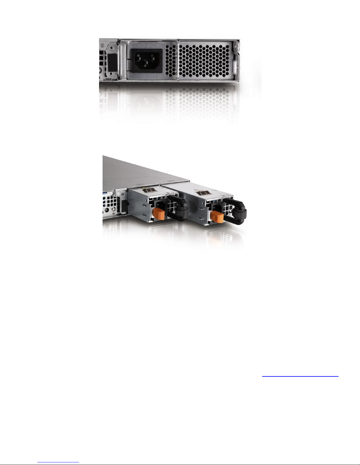
4.6 Power Supply Indicators
The PSUs on the R310 have one status bi-color LED: green LED indicates that AC power is present to the
system when the system is in standby mode. When the system is on, it also indicates that DC power has been
applied to the system for AC power present and amber for a fault.
Dell PowerEdge R310 Technical Guide 17
Figure 4. Back Panel View
Dell
Figure 5. For Non-Redundant PSU
Figure 6. For Redundant PSU
Not lit—AC power is not connected.
Green—In standby mode, a green light indicates that a valid AC source is connected to the power supply
and that the power supply is operational. When the system is on, a green light also indicates that the power
supply is providing DC power to the system.
Amber—Indicates a problem with the power supply.
Alternating green and amber—When hot-adding a power supply, this indicates that the power supply is
mismatched with the other power supply (a high output power supply and an Energy Smart power supply are
installed in the same system). Replace the power supply that has the flashing indicator with a power supply
that matches the capacity of the other installed power supply.
For additional information regarding the power supply indicators, please refer to the Hardware Owner’s Manual.
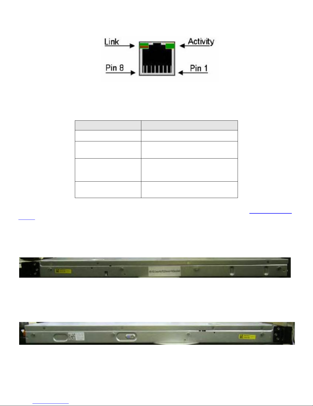
4.7 NIC Indicators
Figure 7 shows the NIC indicators.
Dell PowerEdge R310 Technical Guide 18
Dell
Indicator
Indicator Code
No Link
Off
Link Indicator is Green
The NIC is connected to a valid
network link at 1000 Mbps.
Link Indicator is Amber
The NIC is connected to a valid
network link at 10/100 Mbps.
Activity Indicator is
blinking
Network data is being sent or
received
Figure 7. NIC Indicators
Table 3 shows NIC indicator codes and their meanings.
Table 3. NIC Indicator Codes
For additional information regarding the NIC indicators and their status please refer to the Hardware Owner’s
Manual.
4.8 Side Views and Features
Figure 8. Right Side
Dell PowerEdge R310 Technical Guide 19
Figure 9. Left Side
Dell
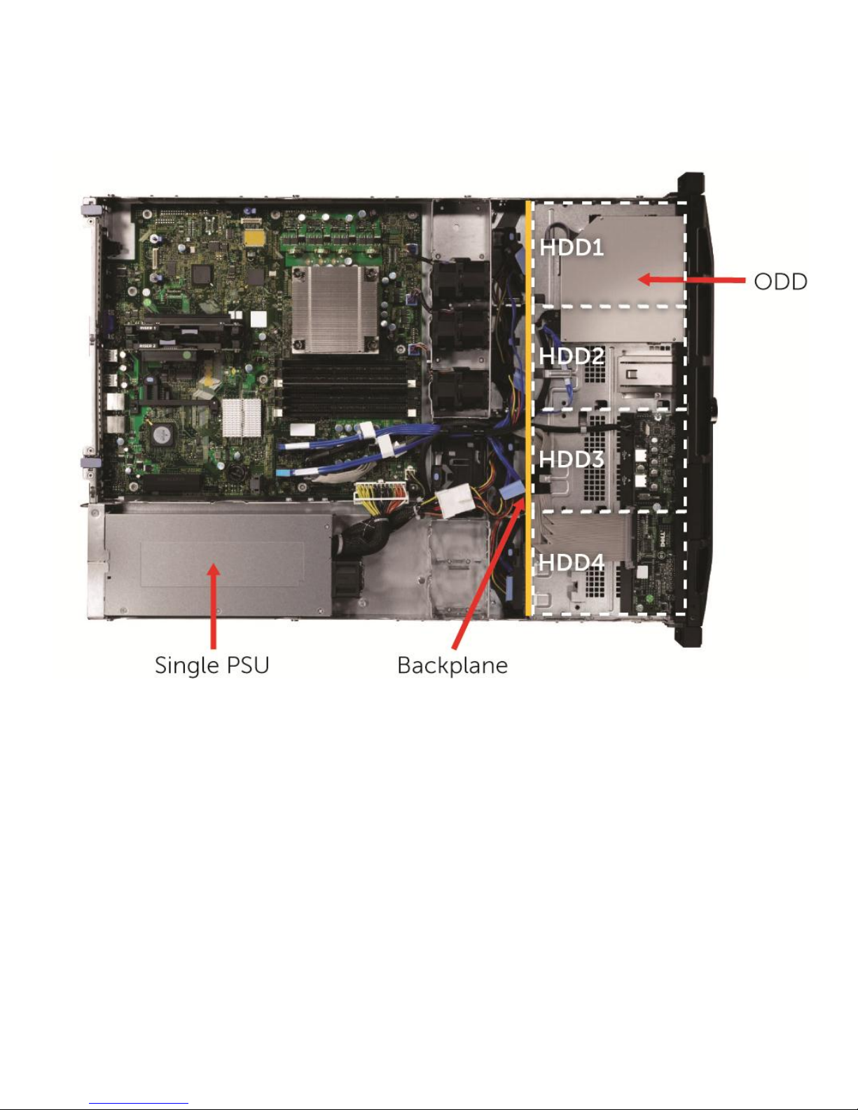
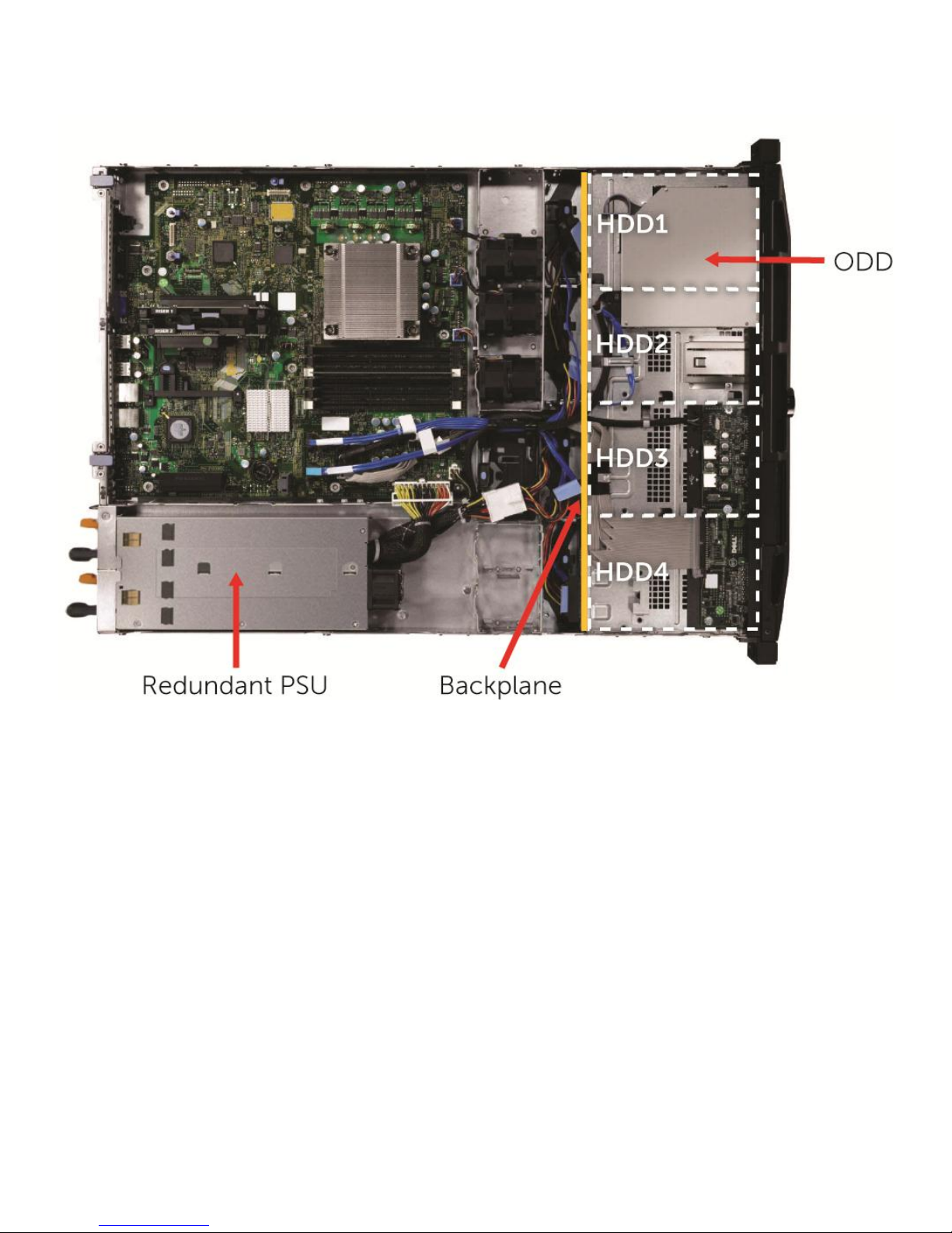
4.9 Internal Chassis Views
Figure 10. Cable HDD Chassis with Single PSU
Dell PowerEdge R310 Technical Guide 20
Dell
Figure 11. Hot Plug HDD Chassis with Redundant PSU
4.10 Rails and Cable Management
ReadyRailsTM Sliding Rails for 4-post Racks:
Support for tool-less installation in 19‖ EIA-310-E compliant square or unthreaded round hole 4-post
racks including all generations of Dell racks
Support for tooled installation in 19‖ EIA-310-E compliant threaded hole 4-post racks (requires the 1U
Threaded Rack Adapter Brackets Kit)
Support for full extension of the system out of the rack to allow serviceability of key internal
components
Support for optional cable management arm (CMA)
Rail depth without the CMA: 714 mm
Rail depth with the CMA: 835 mm
Square-hole rack adjustment range: 686-883 mm
Round-hole rack adjustment range: 672-876 mm
Threaded-hole rack adjustment range: 651-897 mm
Dell PowerEdge R310 Technical Guide 21
Dell
ReadyRailsTM Static Rails for 4-post & 2-post Racks:
Support for tool-less installation in 19‖ EIA-310-E compliant square or unthreaded round hole 4-post
racks including all generations of Dell racks
Support for tooled installation in 19‖ EIA-310-E compliant threaded hole 4-post and 2-post racks
Rail depth: 622 mm
Square-hole rack adjustment range: 608-879 mm
Round-hole rack adjustment range: 594-872 mm
Threaded-hole rack adjustment range: 604-890 mm
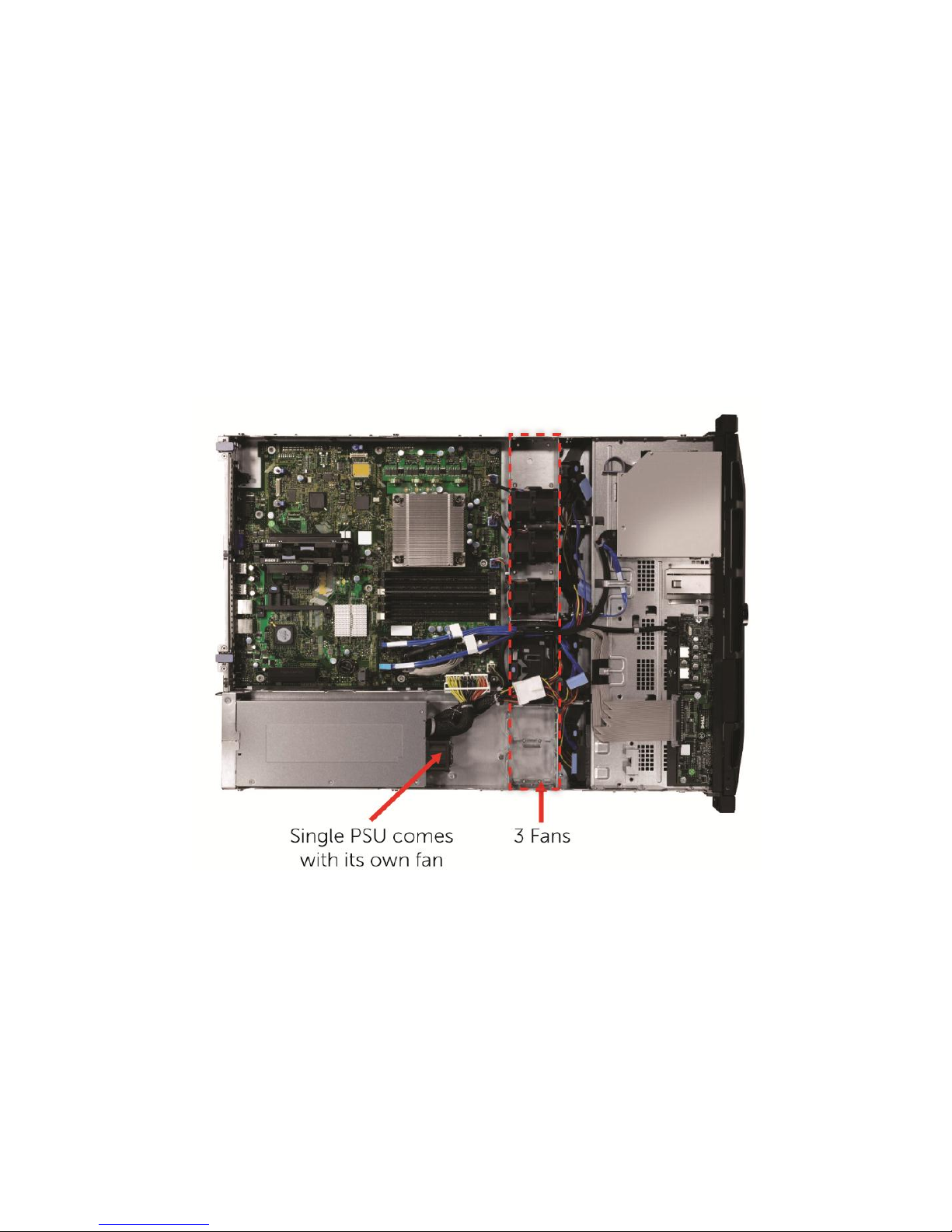
4.11 Fans
There are up to five fans in the chassis when a redundant PSU is configured with the system or three if
configured with non-redundant PSU. Refer to the figures below for further detail.
Figure 12. Non-Redundant PSU Fan Configuration (3 Fans)
Dell PowerEdge R310 Technical Guide 22

Dell
Figure 13. Redundant PSU Fan Configuration (5 Fans)
Additional details regarding the fans for the R310 include:
The Embedded Server Management logic in the system will control and monitor the speed of the fans. A
fan failure or over-temperature in the system will result in a notification from iDRAC6.
The R310 power supply units do not have any integrated fans; they are cooled by the system fan in front
of them. The system requires a PSU blank (metal cover) in place of the empty power supply slot.
System fan speed is pulse-width modulated.
Fans are non-redundant and not hot-swappable.
4.12 Cabling
All cables are clearly marked with Dell part numbers.
Dell PowerEdge R310 Technical Guide 23
Dell
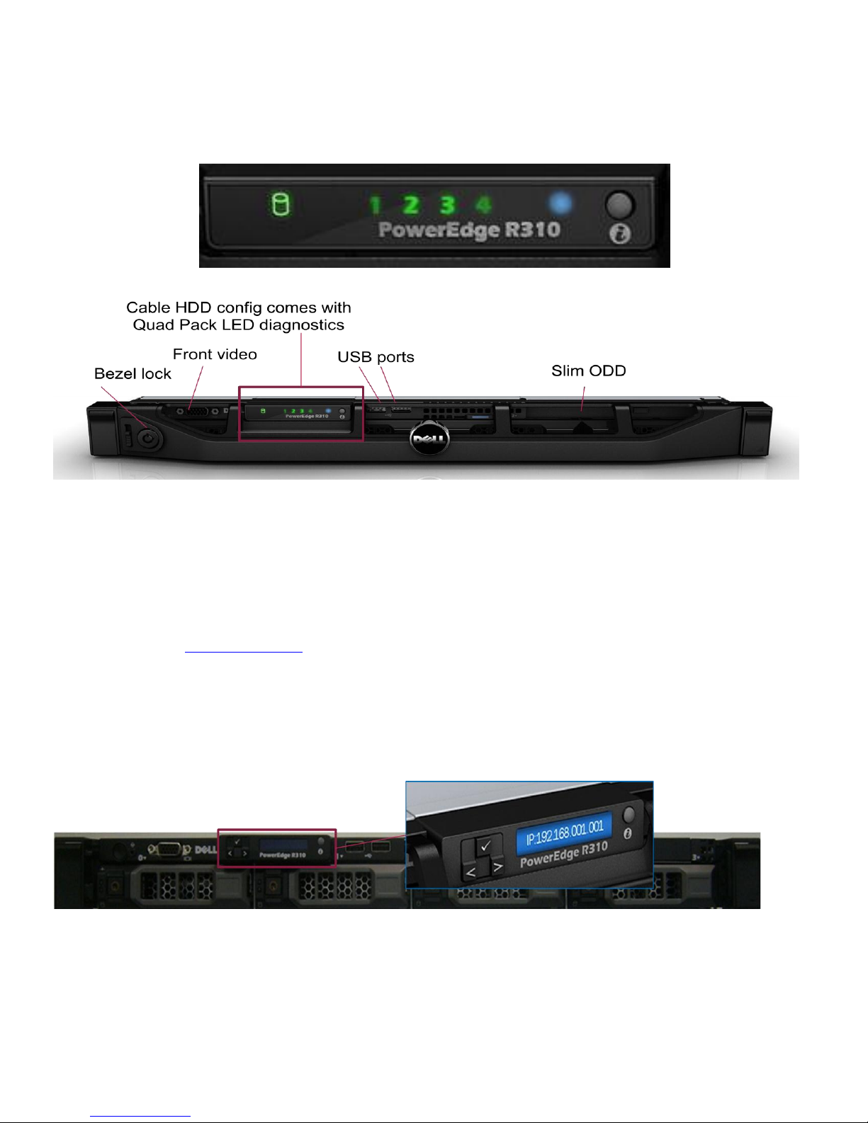
4.13 Control Panel LED & LCD
The R310 comes with an LED Configuration and an optional LCD.
Figure 14. LED Control Panel
4.14 LED Status Description
For a complete description of indicators, causes and possible courses of action to take to resolve errors,
please refer to Diagnostic Lights section in the Hardware Owner’s Manual.
4.15 R310 LCD (Optional) Configuration
The hot-swap HDD configuration comes with LCD panel diagnostics.
The system control panel is located on the front of the system chassis to provide user access to buttons,
display, and I/O interfaces. Features of the system control panel include:
Dell PowerEdge R310 Technical Guide 24
Figure 15. System Control Panel

Dell
ACPI-compliant power button with an integrated green power LED (controlled by iDRAC6)
128x20 pixel LCD panel with controls
o Two navigation buttons
o One select button
o One system ID button
Non-Maskable Interrupt (NMI) button (recessed)
Ambient temperature sensor
Two external USB 2.0 connectors (with an internal USB connector and Internal SD Module)
15-pin VGA connector
The LCD panel is a graphics display controlled by iDRAC6. Error codes can be sent to the display by either
iDRAC6 or BIOS.
The system's LCD panel provides system information and status messages to signify when the system is
operating correctly or when the system needs attention.
The LCD backlight is blue during normal operating conditions and changes to amber to indicate an error
condition. When the system is in standby mode, the LCD backlight is off and can be turned on by pressing
the Select button on the LCD panel. The LCD backlight will remain off if the "No Message" option is selected
through the iDRAC6, the LCD panel, or other tools.
BIOS has the ability to enter a ―Secure Mode‖ through Setup, which locks the Power and NMI buttons. When
in this mode, the Power button can still be used to turn on the system, but it cannot be used to turn off
power to the system.
Dell PowerEdge R310 Technical Guide 25
 Loading...