

Page 1

Dell Express Flash NVMe PCIe SSD User’s
Guide
May 20 20
Rev . A 01
Page 2

Notes, cautions, and warnings
NOTE: A NOTE indicates important information that helps you make better use of your product.
CAUTION: A CAUTION indicates either potential damage to hardware or loss of data and tells you how to avoid
the problem.
WARNING: A WARNING indicates a potential for property damage, personal injury, or death.
© 2019-2020 Dell Inc. or its subsidiaries. All rights reserved. Del l, EMC , and other trademarks are trademarks of Dell Inc. or its
subsidiaries. Other trademarks may be trademarks of their respec tiv e o wne rs.
Page 3

Contents
Chapter 1: NVMe PCIe SSD overview.............................................................................................4
NVMe PCIe SSD U.2...........................................................................................................................................................4
NVMe PCIe SSD AIC.......................................................................................................................................................... 5
NVMe PCIe SSD features..................................................................................................................................................5
Hot swap an NVMe PCIe SSD U.2 device............................................................................................................... 5
Device health.................................................................................................................................................................. 6
Boot from an NVMe PCIe SSD U.2...........................................................................................................................6
Chapter 2: Configure an NVMe PCIe SSD in different operating systems.......................................7
Windows.................................................................................................................................................................................7
Support for Surprise Removal in Windows.............................................................................................................. 7
Linux........................................................................................................................................................................................ 7
VMware..................................................................................................................................................................................8
Chapter 3: Troubleshooting...........................................................................................................9
NVMe PCIe SSD carrier LED indicators.........................................................................................................................9
Ungraceful system shutdown or power loss............................................................................................................... 10
General errors..................................................................................................................................................................... 10
NVMe drive properties intermittently not available in iDRAC........................................................................... 10
NVMe PCIe SSD is not listed in the operating system....................................................................................... 10
I/O device error on write to NVMe PCIe SSD...................................................................................................... 10
NVMe PCIe SSD performance measurement not optimal.................................................................................. 11
System becomes unresponsive when NVMe PCIe SSD is surprise removed................................................ 11
System becomes unresponsive or fails when NVMe PCIe SSD is inserted....................................................11
Chapter 4: Related documentation............................................................................................... 12
Chapter 5: Getting help............................................................................................................... 14
Locating your system Service Tag.................................................................................................................................14
Contacting Dell EMC.........................................................................................................................................................14
Documentation feedback................................................................................................................................................. 14
Contents 3
Page 4
NVMe PCIe SSD overview
Dell NVMe PCIe SSD products include both 2.5-inch (U.2) and add-in controller (AIC) form factors.
Storage management applications enable you to manage and configure the NVMe PCIe SSD. These applications also allow you
to control and monitor multiple NVMe PCIe SSDs, and provide online maintenance.
The NVMe PCIe SSD solution supports Unified Extensible Firmware Interface (UEFI) and Human Interface Infrastructure (HII)
for pre-operating system device management, OpenManage Server Administrator (OMSA) application for operating system
device management, and Integrated Dell Remote Access Controller (iDRAC) with Lifecycle Controller for local or remote device
management. The NVMe PCIe SSD solution supports UEFI, HII, and iDRAC with Lifecycle Controller management on select
PowerEdge systems only. OMSA for NVMe PCIe SSD device management is available on all supported PowerEdge systems.
NOTE: The Instant Secure Erase feature on NVMe PCIe SSD drives is compliant with National Institute for Standards and
Technology 800-88R1 requirements.
NOTE: This documentation assumes you use OMSA, iDRAC, or HII for all management and configuration tasks. See Related
documentation for links to information about the use of these tools.
NOTE: For the safety, regulatory, and ergonomic information associated with these devices, and for more information
about iDRAC/LC remote management, see your platform documentation.
1
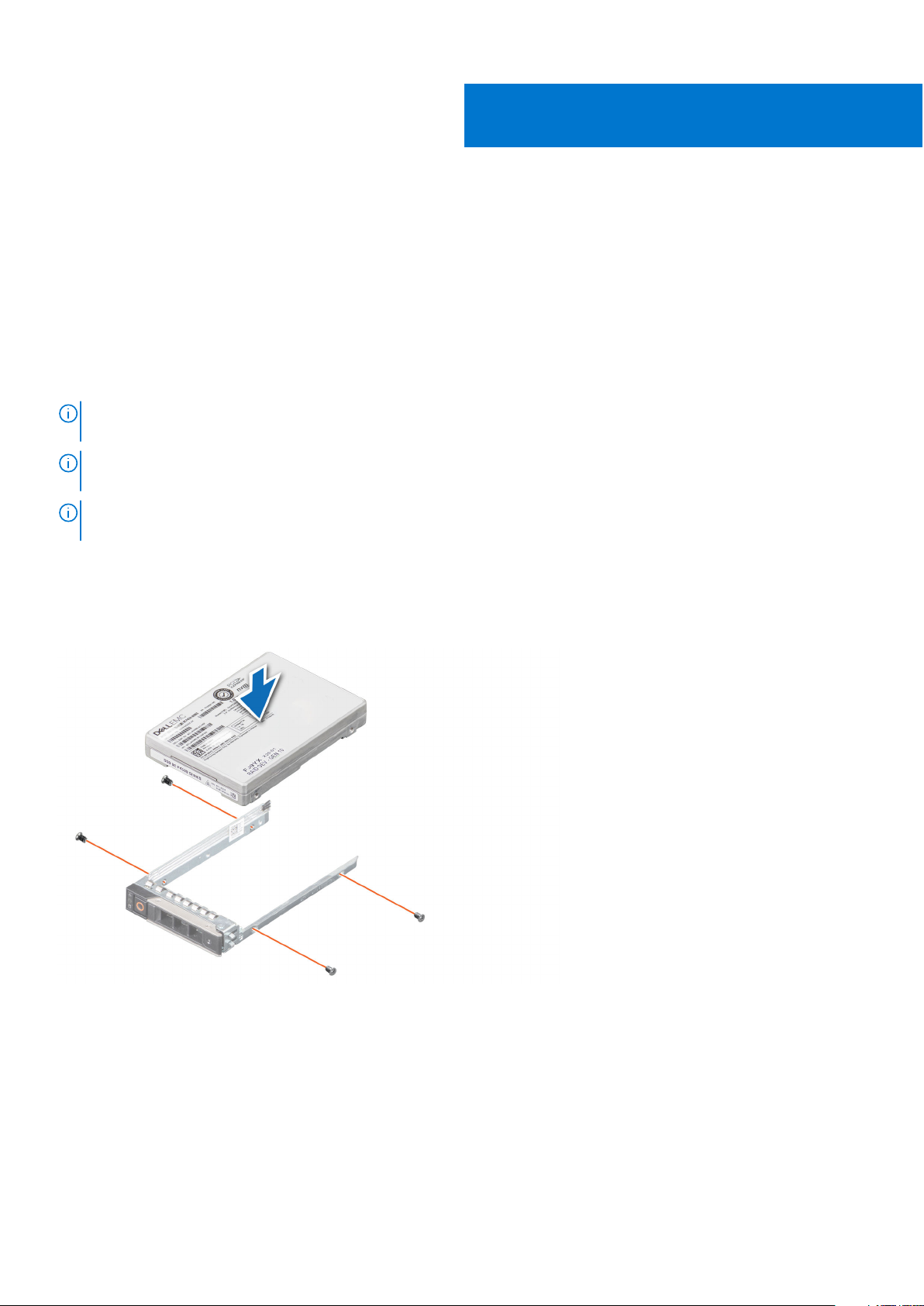
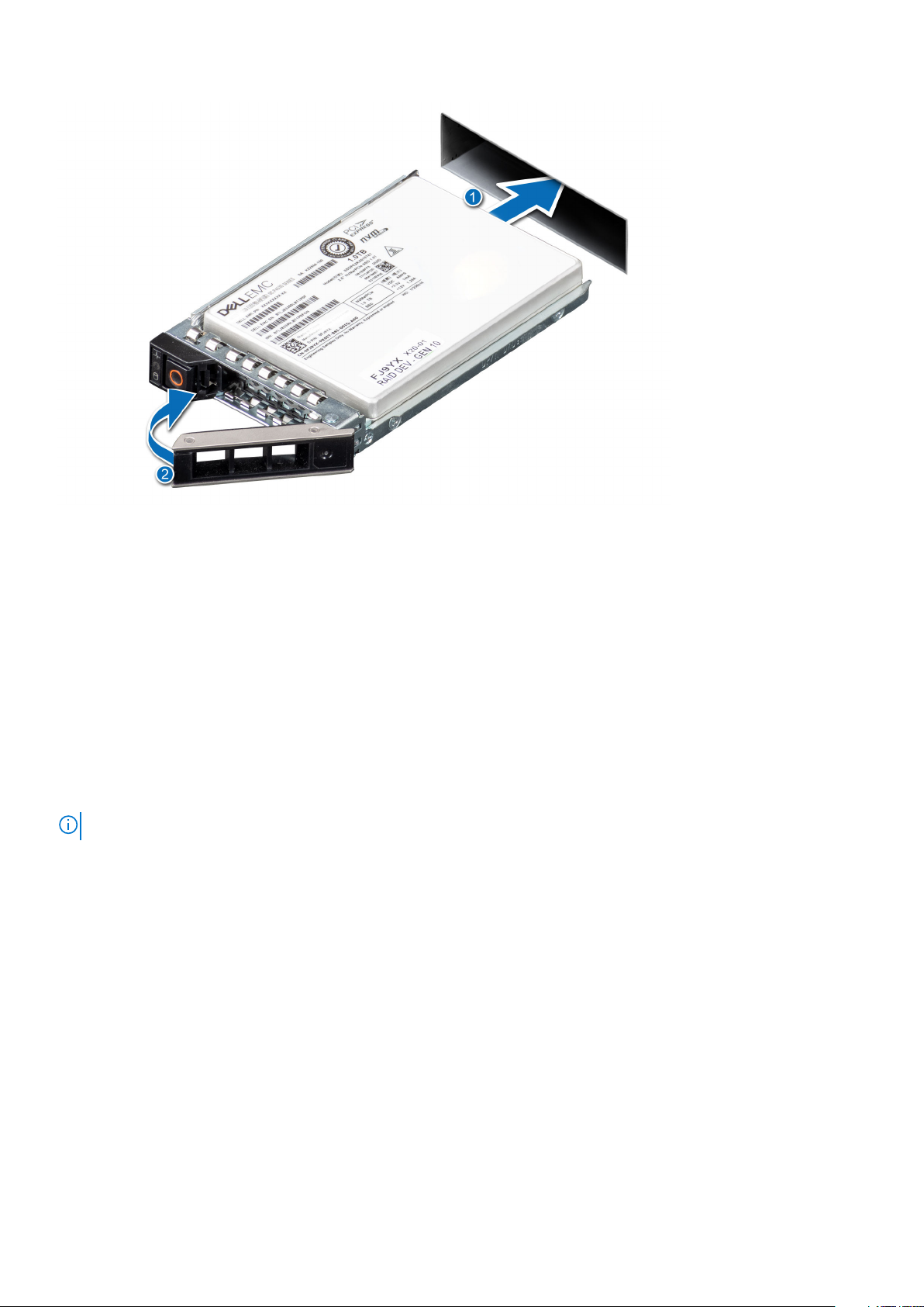
NVMe PCIe SSD U.2
Install the NVMe PCIe SSD U.2 into its carrier before installing it into the server.
4 NVMe PCIe SSD overview
Page 5
NVMe PCIe SSD AIC
Install the NVMe PCIe SSD AIC form factor into the appropriate system board slot. See your server documentation for more
information.
NVMe PCIe SSD features
NVMe PCIe SSDs offer features including hot swap, device health, SMART, remaining rated write, device write status, and boot
capabilities.
Hot swap an NVMe PCIe SSD U.2 device
NOTE: NVMe PCIe SSD AICs do not support hot swap.
Supported NVMe PCIe SSD U.2 device hot swappable functions are defined below:
Orderly or Hot
Insertion
Orderly Removal Remove a device from a running system. Prior to physically removing the device, you must notify the
Orderly Swap Remove a device from the system in an orderly fashion and replace it with a supported device. The device
Surprise Removal Remove a device from a running system without first notifying the system that the device is about to be
Insert a device into a running system where a similar device has not been previously inserted from the
time it was last booted. The systems that support NVMe PCIe SSDs are configured to handle PCIe
resource balancing in the event of a hot insertion when operating within a Dell supported operating
system. This preset system configuration makes hot insertion an orderly operation if performed with
supported operating systems.
system that the device is about to be removed. This notification defines hot removal as an orderly
operation.
that is removed and the device that replaced it use the same device driver.
removed. This feature is supported on systems running Microsoft Windows 2019 or later. See Support for
Surprise Removal in Windows for information about how to use this function.
NVMe PCIe SSD overview 5
Page 6

Device health
Dell Express Flash NVMe PCIe SSDs include several features such as SMART, remaining rated write endurance, and device write
status, that allow you to monitor device health.
Use these features to help maintain the health of your Dell Express Flash SSD.
Self-Monitoring Analysis and Reporting Technology (SMART)
Dell management tools such as Integrated Dell Remote Access Controller and Dell OpenManage Server Administrator use
SMART to provide alert content.
Remaining rated write endurance
The NVMe PCIe SSD is warrantied to a maximum amount of data written to the device in total bytes written. The NVMe PCIe
SSD self monitors for these limits, and software management applications notify you when you reach these limits.
NOTE: If you continue to write to the device after it reaches the threshold of total bytes written, the amount of time
the NVMe PCIe SSD retains data while powered off decreases below device specifications. For more information, see the
technical specification sheet for your SSD.
Device write status
If the device exhausts the available spare sectors, the NVMe PCIe SSD enters Write Protect (Read-Only) mode. In Write
Protect mode, you can only perform read operations to the device. The NVMe PCIe SSD self monitors for these limits, and
software management applications notify you when you reach these limits.
Boot from an NVMe PCIe SSD U.2
NOTE: You cannot boot from an NVMe PCIe SSD AIC.
Dell supports installation of operating systems to, and booting from, NVMe PCIe SSD U.2s on select PowerEdge platforms that
have been configured for UEFI BIOS boot mode. To determine whether or not an NVMe PCIe SSD U.2 may be used as a boot
device on your system, see the system-specific documentation at www.dell.com/manuals.
6
NVMe PCIe SSD overview
Page 7

2
Configure an NVMe PCIe SSD in different
operating systems
The NVMe PCIe SSD you ordered with your system is pre-configured and ready for use. The following describes how to access
those settings.
Windows
In Windows-based systems, NVMe PCIe SSD devices have a controller entity and a device entity. The controller entity is
displayed under the Storage controller menu in the Device Manager.
NOTE: When configured in Dell S140 RAID volumes, separate device entries are not shown. For more information, see the
Dell S140 documentation at www.dell.com/manuals.
Use the controller entity when installing or updating the NVMe PCIe SSD driver. You can configure the NVMe PCIe SSD for use
in Windows from Computer Management > Storage > Disk Management Tool.
Support for Surprise Removal in Windows
It is recommended that you notify the system prior to removing an NVMe PCIe SSD U.2 even though you can remove an NVMe
PCIe SSD U.2 without prior notification in Windows system.
CAUTION:
ensure that the data on your drive is no longer in use.
NOTE: It is strongly recommended that you notify the system prior to removing an NVMe PCIe SSD U.2. Refer
the OpenManage Server Administrator documentation at, www.dell.com/openmanagemanuals > OpenManage Server
Administrator or iDRAC User's Guide available at www.dell.com/idracmanuals for more information.
NOTE: Orderly hot swap is only supported when an NVMe PCIe SSD device is installed in a supported Dell system running
a supported operating system. Do not insert or remove an NVMe PCIe SSD device while accessing the system BIOS or
Hll configuration. To ensure that you have the correct hardware setup for your NVMe PCIe SSD device, see the system
specific owner's manual at www.dell.com/manuals.
To prevent data loss or corruption when doing a surprise removal of an NVMe PCIe SSD U.2 device,
Linux
On Linux-based systems, you can configure NVMe PCIe SSDs from the partitioning tool by specifying or selecting the device
name. The device name for NVMe PCIe SSDs is /dev/nvmeXn1, where X is the number corresponding to each NVMe PCIe
SSD in the system. For example:
/dev/nvme0n1
/dev/nvme1n1
/dev/nvme2n1
Use OpenManage Server Administrator for managing and performing NVMe PCIe SSD-related tasks.
NOTE: Surprise removal is not supported on Linux-based systems.
Configure an NVMe PCIe SSD in different operating systems 7
Page 8

VMware
In VMware systems, you can use vSphere Client to configure an NVMe PCIe SSDs as a datastore or for passthrough operation.
However, configuring an NVMe PCIe SSD for passthrough operation is not recommended due to the following limitations:
● Inability to take snapshots of the Virtual Machine (VM).
● VM is no longer able to use fail over features such as VMotion and Distributed Resources Scheduler (DRS).
● Loss of hot swap capability for other devices such as USB drives. To add another device, you must first shut down the VM.
Configuring an NVMe PCIe SSD for passthrough operation is not recommended except as defined by Dell-specific solutions.
See the solution-specific documentation at www.dell.com/manuals.
NOTE: Surprise removal is not supported on VMware systems.
8 Configure an NVMe PCIe SSD in different operating systems
Page 9

3
Troubleshooting
NOTE: To get help for your NVMe PCIe SSD, see Contacting Dell EMC.
NVMe PCIe SSD carrier LED indicators
The LEDs on the NVMe PCIe SSD U.2 carrier indicate the state of each physical device. Each NVMe PCIe SSD carrier in your
enclosure has an activity LED (green) and a status LED (bicolor, green/amber). The activity LED flashes whenever the device is
accessed.
Figure 1. NVMe PCIe SSD device carrier LED indicators
1. status indicator
2. activity indicator
3. release button
While the operating system is running, the status indicator provides the current status of the device. The following table lists
the device states along with the associated LED indicator codes.
Table 1. NVMe PCIe SSD U.2 states and LED indicator codes
State Name Slot/Device State Status LED (Green) Status LED (Amber)
Device status off The server or device is not
powered up.
Device online The device is powered up. On Off
Device identify (blink) The device is identifying the
slot location or is indicating
the device has received a
Prepare for Removal
command from the host
operating system.
Device failed The host operating system
no longer has access to the
device because the device
is not responding or has
encountered a critical error
condition.
Off Off
On for 250 msec
Off for 250 msec
Off
Off
On for 250 msec
Off for 250 msec
Read only The device will only service
read operations.
Predicted failure The SMART feature set has
predicted a degradation or
fault condition.
Off
Off for 250 msec
On for 250 msec
On for 250 msec
Off for 250 msec
On for 250 msec
Off for 250 msec
Troubleshooting 9
Page 10

Ungraceful system shutdown or power loss
If the host system experiences a power loss, the NVMe PCIe SSD may not have time to perform its internal shut down
procedure. In such an event, the device may enter a recovery mode.
This recovery process is also known as rebuilding. During rebuilding, there is very limited access from the host operating system.
After the recovery procedure is complete, the device is fully accessible from the host operating system.
NOTE: Dell recommends that you use power backup solutions for all Dell systems.
General errors
The following section describes general errors related to NVMe PCIe SSD.
NVMe drive properties intermittently not available in iDRAC
Description NVMe drive properties via sideband (iDRAC) may not be available after a PCIe SSD is hot-inserted into
the system. This is most likely to occur if the PCIe SSD is formatted with a file system or has existing
data.
Cause Side band controller on the NVMe drives does not complete initialization in time for iDRAC to inventory
the device.
Solution After an AC power cycle, the system should list the inserted devices in iDRAC.
NVMe PCIe SSD is not listed in the operating system
Cause
Solution Check the following components:
Hardware is not correctly installed.
● Devices: Ensure that the NVMe PCIe SSDs are installed in an NVMe PCIe SSD backplane.
NOTE: NVMe PCIe SSDs must be used with NVMe PCIe SSD backplanes. To ensure that you
have the correct configuration for the NVMe PCIe SSD, see the platform-specific owner’s manual
at www.dell.com/manuals.
● Backplane: Ensure that the cables for the NVMe PCIe SSD backplane are connected correctly.
● Cables: PCIe cables are unique for the configuration. Ensure that the backplane cable connectors are
connected to the backplane and the extender card or system board.
● Extender card: Ensure that the PCIe extender card, if used in your server configuration, is plugged
into the correct supported slot. See the system-specific owner's manual at www.dell.com/manuals.
I/O device error on write to NVMe PCIe SSD
Description
Windows event log may report the following entries on the first write attempt to an NVMe PCIe SSD:
Event ID 7: The device, \Device\Harddisk\DRX, has a bad block.
When attempting to initialize the device using Computer Management > Storage > Disk
Management, the following message is displayed: Virtual Disk Manager, Data Error
(cyclic redundancy check).
Linux messages log may report the following entries on a write attempt to an NVMe PCIe SSD:
● Buffer I/O error on device nvmeXn1, logical block Y (where X is the
number corresponding to the device and Y is the logical block)
● nvmeXn1: unable to read partition table (where X is the number
corresponding to the device)
10 Troubleshooting
Page 11

Cause NVMe PCIe SSDs have a finite number of write cycles. When an NVMe PCIe SSD exhausts the number of
writes, it goes into Write Protect (Read Only) mode.
Solution By using system management applications, you may check the NVMe PCIe SSD state to confirm if
the NVMe PCIe SSD is in Read-Only Mode. For further instructions, contact a Dell Technical Service
representative.
NVMe PCIe SSD performance measurement not optimal
Description There are several factors that may alter the performance of an NVMe PCIe SSD. It is recommended that
you configure performance optimization of these devices using the basic setup options.
Cause NVMe PCIe SSD has not been preconditioned, or the BIOS settings are not optimized.
Solution Without preconditioning the NVMe PCIe SSD, performance measurements can be misleading as they
might not reflect long-term performance of the device. Preconditioning enables flash management,
which stabilizes data throughput over a period of time. For the Solid-State Storage Performance Test
Specification, see snia.org.
System becomes unresponsive when NVMe PCIe SSD is surprise removed
Description The system becomes unresponsive when the device is removed without first preparing the device for
removal.
Cause Surprise removal is only supported in PowerEdge servers for NVMe PCIe SSD running under Windows.
Solution Execute the Prepare For Removal operation for the specific NVMe PCIe SSD from a Dell Management
application.
System becomes unresponsive or fails when NVMe PCIe SSD is inserted
Description
Cause Hot insertion is not supported in pre-operating system configuration utilities.
Solution
The system becomes unresponsive or fails when inserting an NVMe PCIe SSD while accessing the system
BIOS or HII configuration utilities.
Insert only after allowing the operating system to fully load or when the server is powered off.
Troubleshooting 11
Page 12

Related documentation
To... Refer to...
Install your system into a rack Rack documentation included with your rack solution.
4
Set up your system and know the system technical
specifications
Install the operating system Operating system documentation at www.dell.com/
Get an overview of the Dell Systems Management offerings Dell OpenManage Systems Management Overview Guide at
Configure and log in to iDRAC, set up managed and
management system, know the iDRAC features and
troubleshoot using iDRAC
Know about the RACADM subcommands and supported
RACADM interfaces
Launch, enable and disable Lifecycle Controller, know the
features, use and troubleshoot Lifecycle Controller
Use Lifecycle Controller Remote Services Dell Lifecycle Controller Remote Services Quick Start Guide at
Set up, use, and troubleshoot OpenManage Server
Administrator
Install, use and troubleshoot OpenManage Essentials Dell OpenManage Essentials User’s Guide at www.dell.com/
Getting Started Guide available at www.dell.com/
poweredgemanuals
operatingsystemmanuals
www.dell.com/openmanagemanuals
Integrated Dell Remote Access Controller User's Guide at
www.dell.com/idracmanuals
RACADM Command Line Reference Guide for iDRAC
and CMC at iDRAC RACADM CLI Guide available at
www.dell.com/idracmanuals
Dell Lifecycle Controller User’s Guide at www.dell.com/
idracmanuals > Lifecycle Controller
Dell.com/openmanagemanuals Lifecycle Controller Remote
Services Quick Start Guide available at www.dell.com/
idracmanuals
Dell OpenManage Server Administrator User’s Guide at
www.dell.com/openmanagemanuals > OpenManage Server
Administrator
openmanagemanuals > OpenManage Essentials
Know the system features, remove and install system
components, and troubleshoot components
Know the features of the storage controller cards, deploy the
cards, and manage the storage subsystem
Check the event and error messages generated by the system
firmware and agents that monitor system components
Your product documentation includes:
Getting Started
Guide
Owner’s Manual Provides information about system features and describes how to troubleshoot the system and install or
Rack Installation
Instructions
Administrator’s
Guide
Provides an overview of system features, setting up your system, and technical specifications. This
document is also shipped with your system.
replace system components.
Describes how to install your system into a rack. This document is shipped with your rack solution.
Provides information about configuring and managing the system.
Owner’s Manual at www.dell.com/poweredgemanuals
Storage controller documentation at www.dell.com/
storagecontrollermanuals
Dell Event and Error Messages Reference Guide at For
information about the event and error messages generated
by the system firmware and agents that monitor system
components, go to qrl.dell.com > Look Up > Error Code,
type the error code, and then click Look it up.
12 Related documentation
Page 13

Troubleshooting
Guide
OpenManageServ
er Administrator
User’s Guide
Provides information about troubleshooting the software and the system.
Provides information about using Dell OpenManage Server Administrator to manage your system.
Related documentation 13
Page 14

5
Getting help
Locating your system Service Tag
Your system is identified by a unique Express Service Code and Service Tag number. The Express Service Code and Service Tag
are found on the front of a physical DR Series system by pulling out the information tag. The service tag can also be found on
the Support page in the GUI. This information is used to route support calls to the appropriate personnel for resolution.
Contacting Dell EMC
Dell EMC provides several online and telephone based support and service options. If you do not have an active internet
connection, you can find contact information about your purchase invoice, packing slip, bill, or Dell EMC product catalog.
Availability varies by country and product, and some services may not be available in your area. To contact Dell EMCfor sales,
technical assistance, or customer service issues:
1. Go to Dell.com/support/home.
2. Select your country from the drop-down menu on the lower right corner of the page.
3. For customized support:
a. Enter your system Service Tag in the Enter your Service Tag field.
b. Click Submit.
The support page that lists the various support categories is displayed.
4. For general support:
a. Select your product category.
b. Select your product segment.
c. Select your product.
The support page that lists the various support categories is displayed.
5. For contact details of Dell EMC Global Technical Support:
a. Click Global Technical Support.
b. The Contact Technical Support page is displayed with details to call, chat, or e-mail the Dell EMC Global Technical
Support team.
Documentation feedback
Click the Feedback link in any of the Dell EMC documentation pages, fill out the form, and click Submit to send your feedback.
14 Getting help
 Loading...