

Dell EQUALLOGIC PS6500 Hardware Manual

PS6500 Storage Arrays
Hardware Maintenance
110-0118-EN-R2

Copyright 2010 Dell, Inc. All rights reserved.
Dell is a trademark of Dell, Inc.
EqualLogic is a registered trademark.
All trademarks and registered trademarks mentioned herein are the property of their respective owners.
Information in this document is subject to change without notice.
Reproduction in any manner whatsoever without the written permission of Dell is strictly forbidden.
August 2010
Part Number: 110-0118-EN Rev. 2
ii

Table of Contents
Preface ...................................................................................................................................................... iii
Audience ...................................................................................................................................................................iii
Organization .............................................................................................................................................................iii
Overview of Dell EqualLogic Products ...................................................................................................................iii
Related Documentation ..............................................................................................................................................v
Technical Support and Customer Service ..................................................................................................................v
Warranty Information ................................................................................................................................................vi
1 Basic Array Information ...................................................................................................................................1-1
Field Replaceable Components...............................................................................................................................1-1
Array Bezel and Front Panel................................................................................................................................... 1-2
Hardware Status LEDs ................................................................ .... ..... ............................................................1-3
LCD Panel Display...........................................................................................................................................1-4
Enclosure Switch Settings ................................................................................................................................1-6
Array Back Panel .................................................................................................................................................... 1-6
Serial Number Label ...............................................................................................................................................1-6
Protecting Hardware from Electrostatic Discharge.................................................................................................1-7
Removing and Installing the Bezel.........................................................................................................................1-8
Opening and Closing the Chassis Cover................................................................................................................. 1-9
Using the Cable Management System .................................................................................................................. 1-10
Turning on Power to an Array............................................................................................................................... 1-13
Shutting Down and Turning Off Power to an Array .............................................................................................1-13
Returning Hardware.............................................................................................................................................. 1-14
2 Maintaining Disk Drives .................................................................................................................................... 2-1
Disk Drive LEDs..................................................................................................................................................... 2-1
Disk Drive Status ............................................................. .... ..... .............................................................................. 2-2
Disk Drive Numbering............................................................................................. ..... .... ......................................2-3
Array Behavior When a Disk Drive Fails............................................................................................................... 2-3
Disk Drive Requirements.................................................................................................. ..... . ................................ 2-4
Removing Disk Drives............................................................................................................................................2-4
Installing Disk Drives..................................... .... .....................................................................................................2-7
3 Maintaining Control Modules...........................................................................................................................3-1
Identifying the Control Module............................................................................................................................... 3-1
Interpreting Control Module LEDs......................................................................................................................... 3-1
Identifying Control Module Failures....................................................................................................................... 3-3
Understanding Failover Behavior ........................................................................................................................... 3-3
Maintaining Control Module Firmware.................................................................................................................. 3-3
Control Module Handling Requirements................................................................................................................ 3-4
Removing a Control Module...................................................................................................................................3-4
Installing a Control Module....................................................................................................................................3-6
Replacing the MicroSD Card.................................................................................................................................. 3-7
Removing the MicroSD Card........................................................................................................................... 3-8
Inserting the MicroSD Card.............................................................................................................................. 3-9
Network Requirements and Recommendations....................................................................................................3-10
Connecting Network Cables.................................................................................................................................. 3-11
i

PS6500 Hardware Maintenance
4 Maintaining Power Supply and Cooling Modules.......................................................................................... 4-1
Power Supply and Cooling Module LEDs............................................................... ..... ..........................................4-1
Power Supply and Cooling Module Status .......................................................... .... ...............................................4-2
Array Behavior When a Power Supply Fails..........................................................................................................4-2
Power Requirements and Recommendations.......................................................................................................... 4-3
Removing a Power Supply and Cooling Module.................................................................................................... 4-3
Installing a Power Supply and Cooling Module.....................................................................................................4-4
5 Maintaining Channel Cards.............................................................................................................................. 5-1
Channel Card LEDs ................................................................................................................................................ 5-1
Channel Card Status................................................................................................................................................5-2
Array Behavior When a Channel Card Fails...........................................................................................................5-2
Channel Card Handling Requirements....................................................................................................................5-3
Replacing a Channel Card.......................................................................................................................................5-3
Removing a Channel Card................................................................................................................................ 5-3
Inserting a Channel Card..................................................................................................................................5-4
6 Maintaining the EIP Card.................................................................................................................................6-1
EIP Card LEDs........................................................................................................................................................ 6-1
EIP Card Status ....................................................................................................................................................... 6-3
Array Behavior When an EIP Card Fails................................................................................................................ 6-3
EIP Card Handling Requirements...........................................................................................................................6-3
Replacing the EIP Card...........................................................................................................................................6-3
A Array Technical Specifications ....................................................................................... .... ............................ A-1
Index................................................................................................................................................................Index-1
ii

Preface
This manual describes how to maintain the PS6500 storage array hardware, including disks, channel cards, EIP
card, control modules, and power supply and cooling modules. It also provides basic information about operating
an array .
Audience
This manual is designed for administrators responsible for installing or maintaining PS6500 array hardware.
Administrators are not required to have extensive network or storage system experience. However, it may be useful
to understand:
• Basic networking concepts
• Current network environment
• Disk storage space requirements
• RAID configurations
• Disk storage management
Note: Although this manual provides examples of using PS6500 arrays in some common network configurations,
detailed information about setting up a network is beyond its scope.
Organization
This manual is organized as follows:
• Chapter 1, Basic Array Information, describes the PS6500 array front and back panels and technical
specifications, in addition to basic array operations.
• Chapter 2, Maintaining Disk Drives, describes how to obtain disk drive status and how to install and remove
disk drives.
• Chapter 3, Maintaining Control Modules, describes how to obtain control module status, how to install and
remove a control module, and how to replace the micro SD card.
• Chapter 4, Maintaining Power Supply and Cooling Modules, describes how to obtain module status and how to
install and remove a module.
• Chapter 5, Maintaining Channel Cards, describes how to obtain channel card status and how to install and
remove a channel card.
• Chapter 6, Maintaining the EIP Card, describes how to obtain Enclosure Interface Processor (EIP) card status
and how to install and remove an EIP card.
• Appendix A, Array Technical Specifications, lists the environmental and physical specifications for the array.
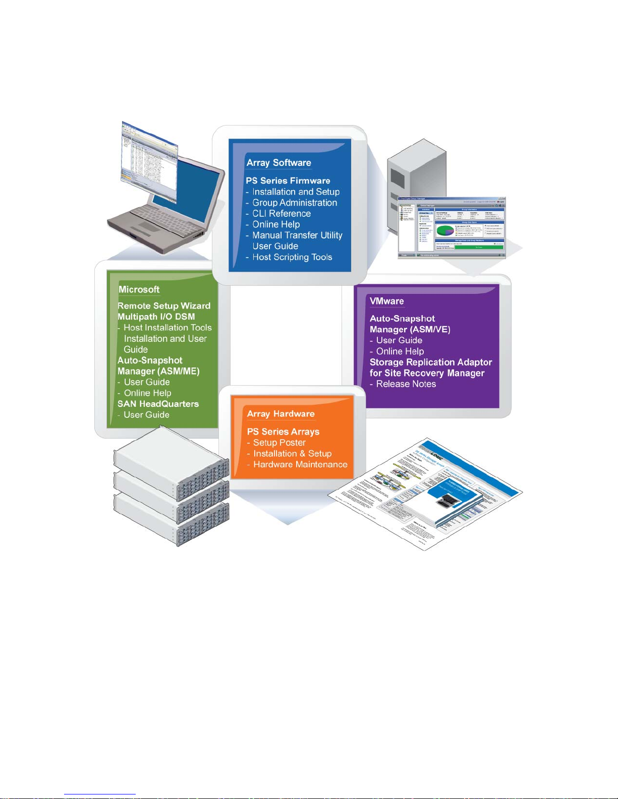
Overview of Dell EqualLogic Products
Thank you for your interest in Dell EqualLogic™ PS Series storage products. We hope you will find them intuitive
and simple to configure and manage.
iii

PS6500 Hardware Maintenance Preface
PS Series arrays optimize resources by automating performance and network load balancing. Additionally, PS
Series arrays offer all-inclusive array management software, host software, and free firmware updates. The features
and products described next are available at no additional cost.
PS Series Array Software
• Firmware - Installed on each array, PS Series firmware software allows you to manage your storage
environment and provides capabilities such as volume snapshots, cloning, and replication to ensure data hosted
on the arrays is protected in the event of an error or disaster.
- Group Manager GUI: Provides a graphical user interface for managing a group.
- Group Manager CLI: Provides a command line interface for managing a grou p.
• Manual Transfer Utility (MTU) – Runs on Windows and Linux systems and enables you to use physical media
to securely transfer large amounts of data to a replication partner, facilitating replication and preventing
network congestion.
Host Software for Windows
• Host Integration Tools
- Remote Setup Wizard (RSW): Initializes new PS Series arrays, configures host connections to PS Series
groups, and configures and manages multipathing.
- Multipath I/O Device Specific Module (MPIO DSM): Includes a connection awareness-module that
understands PS Series network load balancing and facilitates host connections to PS Series volumes.
- VSS and VDS Provider Services: Allows 3rd party backup software vendors to perform off-host backups.
- Auto-Snapshot Manager/Microsoft Edition (ASM/ME): Uses PS Series snapshots, cloning, and replication
to provide point-in-time protection of critical data for supported applications, including SQL Server,
Exchange Server, Hyper-V, and NTFS file shares.
• SAN HeadQuarters (SANHQ): Provides centralized monitoring, historical performance trending, and event
reporting for multiple PS Series groups.
Host Software for VMware
• Storage Adapter for Site Recovery Manager (SRM): Allows SRM to understand and recognize PS Series
replication for full SRM integration.
• Auto-Snapshot Manager/VMware Edition (ASM/VE): Integrates with VMware Virtual Center and PS Series
snapshots to allow administrators to enable Smart Copy protection of Virtual Center folders, datastores, and
virtual machines.
Current Customers Please Note: You may not be running the latest versions of the tools and software listed above.
If you are under a valid warranty or support agreement for your PS Series array , you are entitled to obtain the latest
updates and new releases as they become available.
iv
PS6500 Hardware Maintenance Preface
Related Documentation
For detailed information about PS Series arrays, groups, volumes, array software, and host software, see the
following documentation:
Technical Support and Customer Service
Dell's support service is available to answer your questions about PS Series arrays. If you have an Express Service
Code, have it ready when you call. The code helps Dell's automated-support telephone system direct your call more
efficiently.
Contacting Dell
Dell provides several online and telephone-based support and service options. Availability varies by country and
product, and some services may not be available in your area.
For customers in the United States, call 800-945-3355.
v

PS6500 Hardware Maintenance Preface
Note: If you do not have an Internet connection, you can find contact information on your purchase invoice,
packing slip, bill, or Dell product catalog.
Use the following procedure to contact Dell for sales, technical support, or customer service issues:
1. Visit
support.dell.com or the Dell support URL specified in information provided with the Dell product.
2. Select your locale. Use the locale menu or click on the link that specifies your country or region.
3. Select the required service. Click the "Contact Us" link, or select the Dell support service from the list of
services provided.
4. Choose your preferred method of contacting Dell support, such as e-mail or telephone.
Online Services
You can learn about Dell products and services using the following procedure:
1. Visit
www.dell.com (or the URL specified in any Dell product information).
2. Use the locale menu or click on the link that specifies your country or region.
Warranty Information
The PS6500 array warranty is included in the shipping box. For information about registering a warranty, visit
support.dell.com/EqualLogic.
vi
1 Basic Array Information
This chapter includes information about the location and basic operation of the replaceable components in a
PS6500 storage array, technical specifications, power on and off operations, and how to return failed components.
Field Replaceable Components
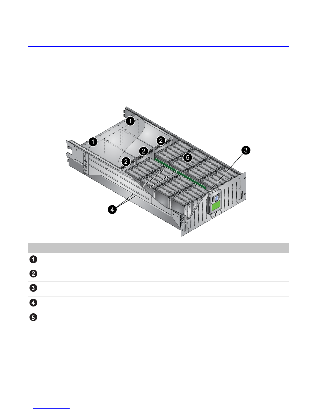
The PS6500 array includes the field-replaceable components shown in Figure 1-1.
Figure 1-1: Field-Replaceable Components
Figure 1-1 Description
Control modules. A PS6500 array includes two control modules.
Power supply and cooling modules. A PS6500 array includes three power supply and cooling modules.
EIP card. A PS6500 array includes one EIP card.
Channel cards. A PS6500 array includes two channel cards.
Disk drives. A PS6500 array includes 48 disk drives. Drives are protected with spare disks and RAID.
You access disk drives, channel cards, and the EIP card from the front of the array. You must remove the bezel and
open the chassis cover to access these components. See Removing and Installing the Bezel on page 1-8 and
Opening and Closing the Chassis Cover on page 1-9.
You access control modules and power supply and cooling modules from the rear of the array.
1–1
PS6500 Hardware Maintenance Basic Array Information
If a field-replaceable component fails, contact your PS Series support provider for information about obtaining a
replacement component.
Notes: Do not remove a component until you are ready to replace it. Do not operate the array for a long time with
a component removed.
To maintain adequate cooling, keep the PS6500 chassis cover closed when possible. If you must open the
cover to access the disk drives, channel cards, or EIP card, minimize the time that the cover is open.
Array Bezel and Front Panel
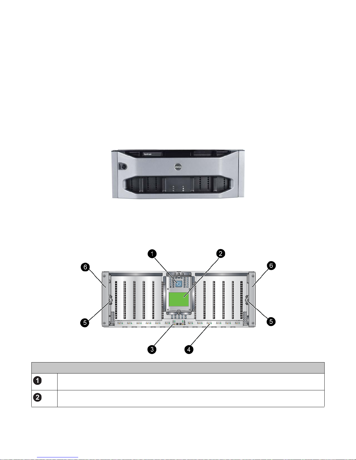
Figure 1-2 shows the bezel of a PS6500 array. The bezel conceals the array front panel and the power switch,
deterring a user from inadvertently turning off power to the array.
Figure 1-2: PS6500 Bezel
You must unlock and remove the bezel to view the front panel, as described in Removing and Installing the Bezel
on page 1-8.
Figure 1-3 shows the array front panel.
Figure 1-3: PS6500 Front Panel
Figure 1-3 Description
Power button. The power button is lit (blue) when you connect at least two power supply and cooling modules to
a source of power.
LCD Panel. If a hardware problem occurs, the affected component and a short description will appear in the LCD
panel. See LCD Panel Display on page 1-4.
1-2
PS6500 Hardware Maintenance Basic Array Information
Figure 1-3 Description
Hardware status LEDs. These LEDs indicate when hardware problems occur. These LEDs can also be seen
when the bezel is installed. See Hardware Status LEDs on page 1-3.
Disk drive LEDs. These LEDs indicate when a drive is present and disk drive activity. See Disk Drive LEDs on
page 2-1.
Cam screws. The two cam screws secure the array front panel to the chassis cover.
Chassis handles. The handles are used to pull out the chassis, opening the cover and exposing the disk drives,
channel cards, and EIP card.
Hardware Status LEDs
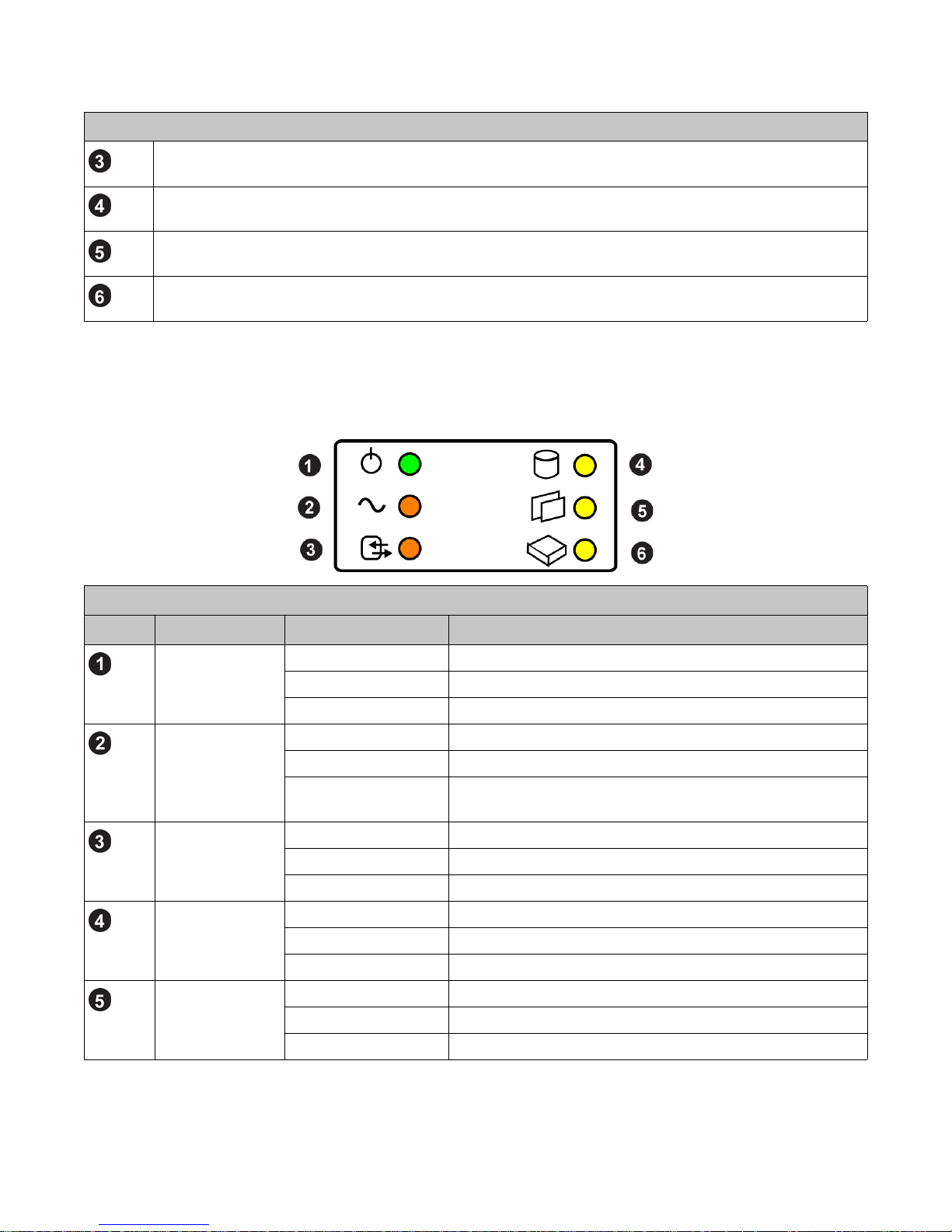
Figure 1-4 shows a detail view of the hard ware status LEDs.
Figure 1-4: PS6500 Hardware Status LEDs
Figure 1-4 Description
Indicator Status Description
Array power Off No power.
Green Normal operation.
Yellow Array is not turned on (standby mode).
Power supply and
cooling modules
Control modules Off Normal operation.
Disk drives Off Normal operation.
Channel cards Off Normal operation.
Off Normal operation.
Flashing orange Module removed.
Orange Power supply failure, fan failure, or upper or lower temperature
limit exceeded.
Flashing orange Module removed or upper or lower temperature limit exceeded.
Orange Module failure.
Flashing yellow One or more disk drive failures.
Yellow Array is running in standby mode.
Flashing yellow Channel card removed.
Yellow Channel card failure.
1-3
PS6500 Hardware Maintenance Basic Array Information
Figure 1-4 Description (Continued)
Indicator Status Description
EIP card Off Normal operation.
Flashing yellow EIP card removed.
Yellow EIP card failure.
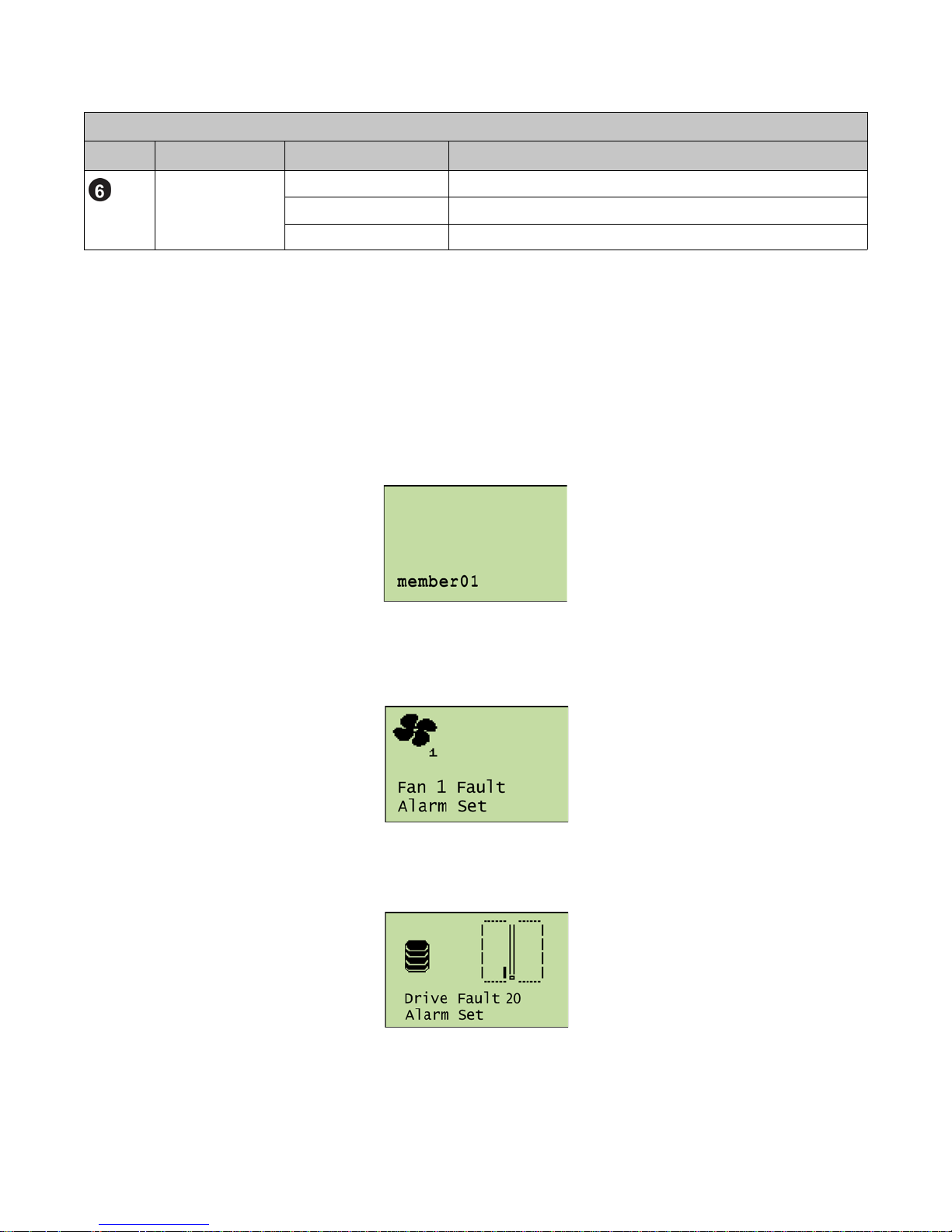
LCD Panel Display
The LCD panel, located on the array front panel behind the bezel, provides information about array hardware
status.
If the array is in standby mode, the word “standby” appears in the LCD panel.
If an array is a member of a group and there are no failures, the member name appears in the LCD panel. See
Figure 1-5.
Figure 1-5: LCD Panel – No Hardware Failures
If a hardware failure occurs, an icon and any numerical identifier for the affected component appear in the LCD
panel. See Figure 1-6.
Figure 1-6: LCD Panel – Fan Failure
If a disk drive fails, you will also see an icon showing the location of the failed drive in the chassis. See Figure 1-7.
Figure 1-7: LCD Panel – Disk Drive Failure
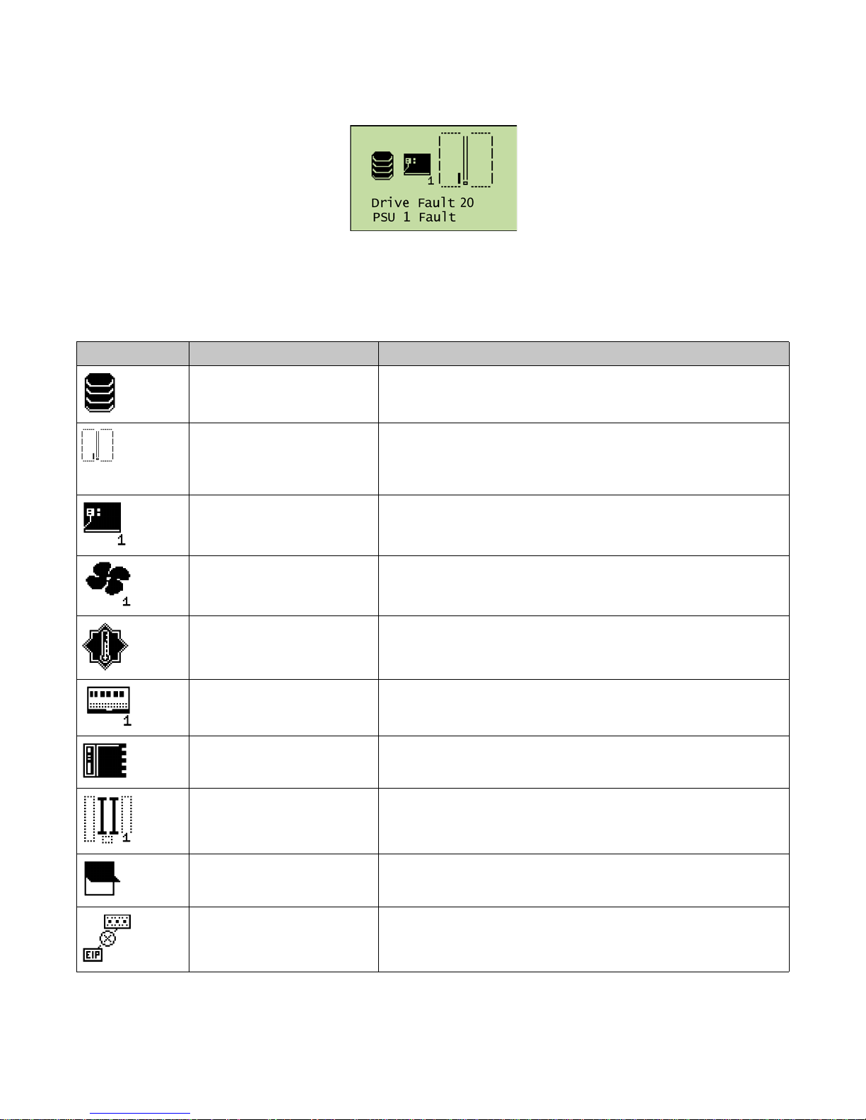
If multiple hardware failures occur simultaneously, the LCD panel displays multiple icons and descriptions. See
Figure 1-8.
1-4
PS6500 Hardware Maintenance Basic Array Information
Figure 1-8: LCD Panel – Disk Drive and Power Supply Failures
Table 1-1 describes the icons used in the LCD panel and the accompanying text.
Note: For detailed information about a hardware failure, use the Group Manager GUI to view the group event log.
Table 1-1: LCD Panel Hardware Icons
Icon Failure Text Description
Drive Fault n
N/A Approximate location of failed disk drive. A PS6500 chassis has 12
PSU n Fault
Disk drive failure, where n specifies the drive number (0 to 47).
columns of four disk drives. From left to right and from the front of the
array to the rear, the first column includes disk drives 0 to 3, the next
column includes disk drives 4 to 7, and so on.
Power supply and cooling module failure, where n (and the number
shown in the icon) specifies the module (
0, 1, or 2, numbered from left
to right when viewed from the rear of the array).
Fan n Fault
Fan failure in a power supply and cooling module, where n (and the
number shown in the icon) specifies the module (
0, 1, or 2, numbered
from left to right when viewed from the rear of the array).
Thermal Fault
I/O card n Fault
Array temperature exceeds upper or lower limit.
Control module failure, where n (and the number shown in the icon)
specifies the control module (
0 or 1, numbered from left to right when
viewed from the rear of the array).
EIP card Fault
Channel Crd n Er
EIP card has failed.
Channel card has failed, where n (and the number shown in the icon)
specifies the card (
0 or 1, numbered from right to left when viewed from
the front of the array).
Enclosure OPEN Chassis cover is open, exposing the disk drives.
Comms Fault The EIP card and active control module have not communicated for
more than 2.5 minutes.
1-5
PS6500 Hardware Maintenance Basic Array Information
Enclosure Switch Settings
Enclosure switches are located between the disk drives and the power supply and cooling modules. You access the
switches by removing the bezel and opening the chassis cover.
Each switch is numbered. Do not change the following default switch settings:
•4 - On
•9 - On
•10 - Off
•11 - On
The other switches are not used.
A switch is on when it is in the position closest to the rear of the chassis. A switch is off when it is in the position
closest to the front of the chassis.
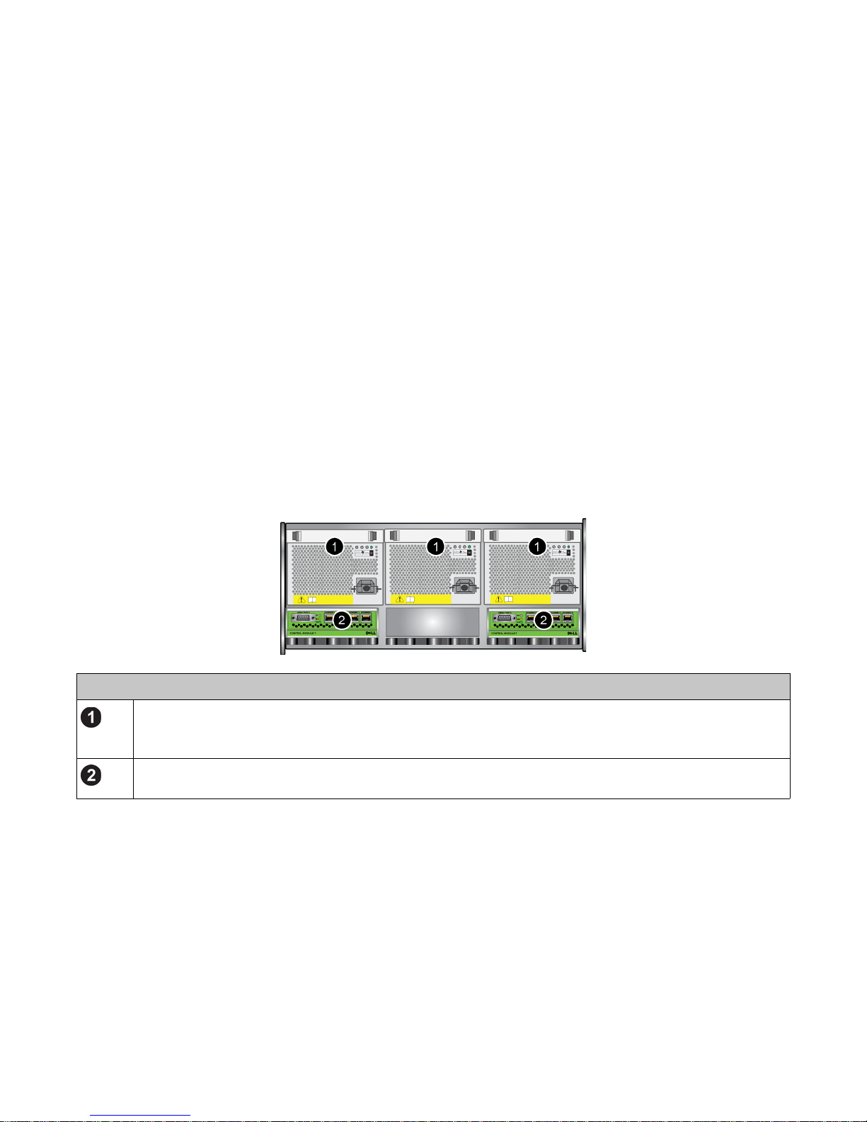
Array Back Panel
Figure 1-9 shows the back panel of a PS6500 array.
Figure 1-9: PS6500 Back Panel
Figure 1-9 Description
Power supply and cooling modules. At least two functioning power supply and cooling modules are required for
array operation. Three modules must be installed to start the array. Power supply and cooling modules are
numbered 0, 1, and 2, from left to right.
Control modules. At least one functioning control module is required for array operation. Control modules are
numbered 0 and 1, from left to right.
See Interpreting Control Module LEDs on page 3-1 and Power Supply and Cooling Module LEDs on page 4-1 for
descriptions of the LEDs shown on the back panel.
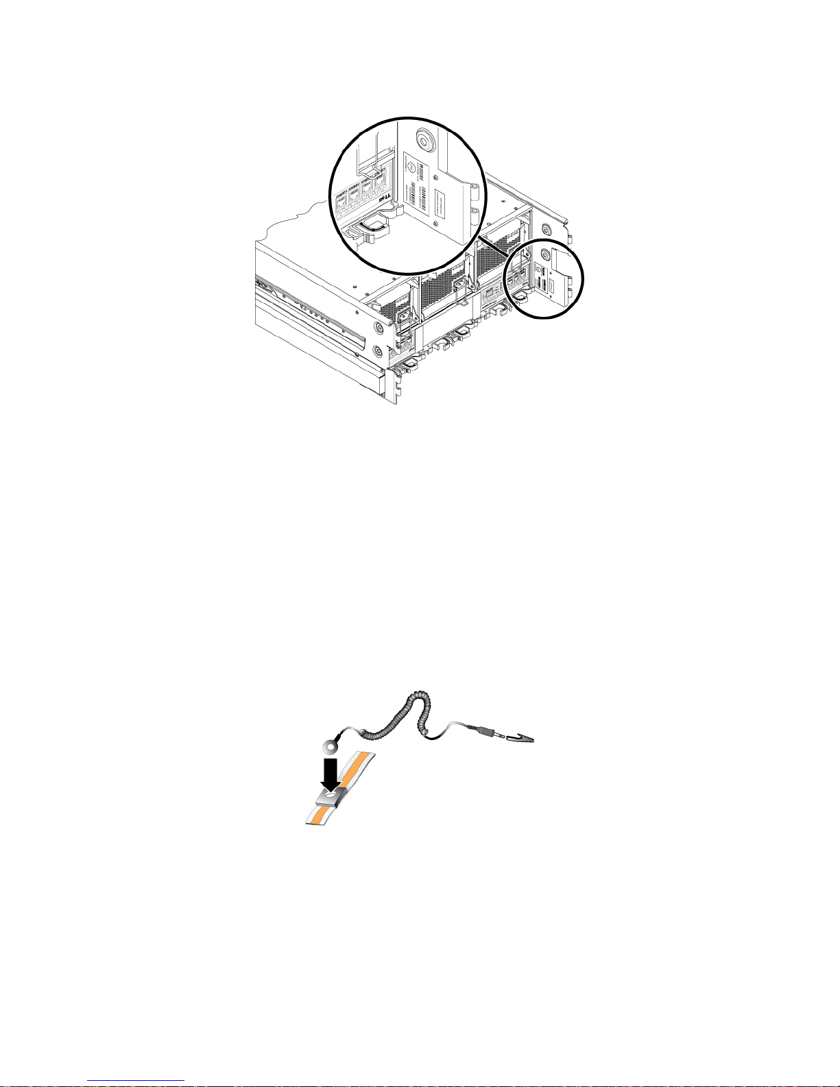
Serial Number Label
The serial number label for the array is on the rear chassis flange. See Figure 1-10.
1-6
PS6500 Hardware Maintenance Basic Array Information
Figure 1-10: Serial Number Label
The serial number is also displayed in the Group Manager GUI. See the Group Administration manual for more
information.
Protecting Hardware from Electrostatic Discharge
When handling the array chassis, disk drives, channel cards, EIP card, or control modules, you must use an
electrostatic protection device to prevent electrostatic discharge. Always store hardware where it is protected from
electrostatic discharge.
An electrostatic wrist strap is supplied in the array shipping box.
To use the wrist strap:
1. Connect the steel snap on the coil cord to the stud on the elastic band. See Figure 1-11.
Figure 1-11: Using an Electrostatic Wrist Strap
2. Fit the band closely around your wrist.
3. Connect the banana plug to ground, or attach the plug to the alligator clip and connect the clip to a grounded
device, such as an ESD mat or the metal frame of a grounded piece of equipment.
1-7
PS6500 Hardware Maintenance Basic Array Information
Removing and Installing the Bezel
You must remove the bezel to access the array front panel, which shows the LCD panel and disk activity LEDs and
provides access to the power button. Also, you must remove the bezel to access the cam screws that lock the
chassis cover.
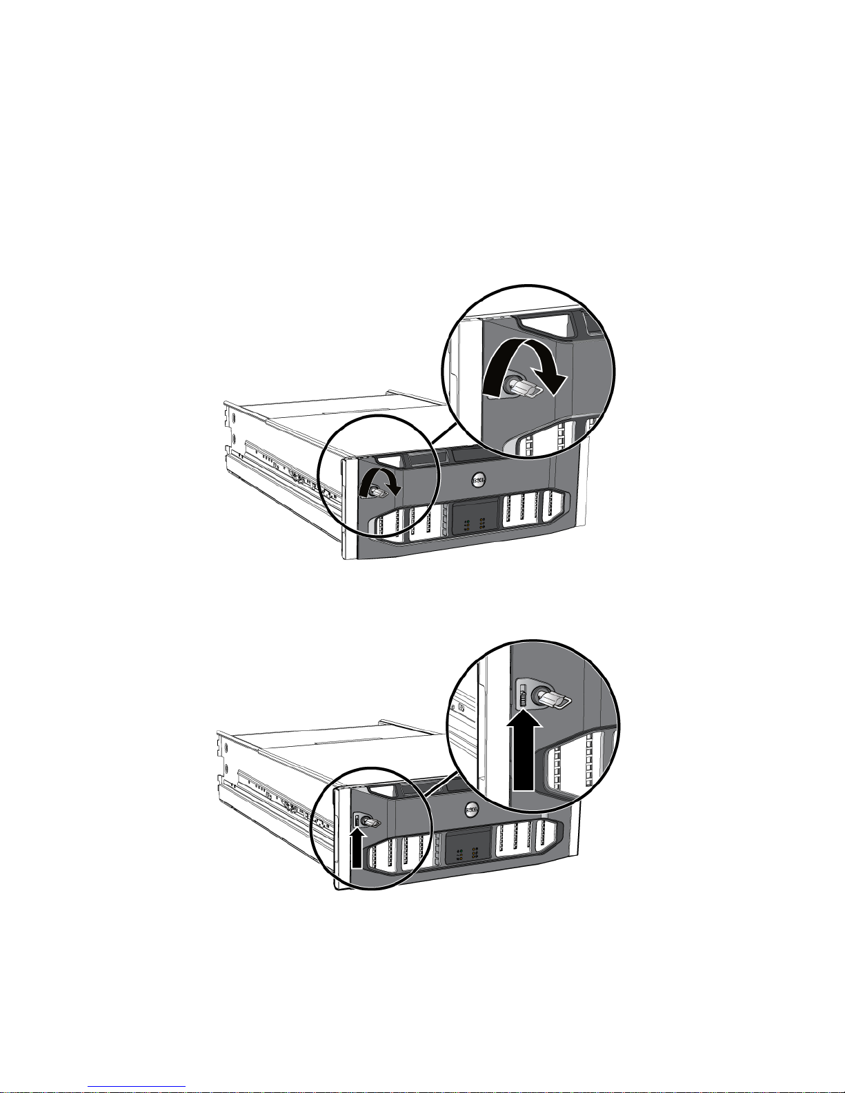
To unlock and remove the bezel:
1. Insert the bezel key and turn it clockwise to unlock the bezel. See Figure 1-12.
Figure 1-12: Unlocking the Bezel
2. Push the bezel release latch up to disengage the bezel from the chassis. See Figure 1-13.
Figure 1-13: Pushing Up the Bezel Release Latch
3. Hold the bezel and pull the bezel away from the chassis. See Figure 1-14.
1-8
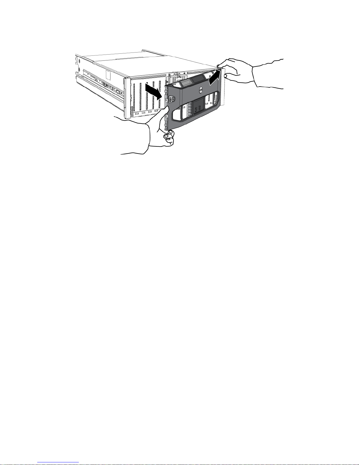
PS6500 Hardware Maintenance Basic Array Information
Figure 1-14: Detaching the Bezel from the Chassis
To install and lock the bezel:
1. Facing the front of the rack, fit the right side of the bezel into the right side of the chassis.
2. Push the bezel toward the chassis until the left side of the bezel engages with the chassis.
3. Insert the bezel key and turn it counter-clockwise to lock the bezel to the chassis.
Opening and Closing the Chassis Cover
To access disk drives, channel cards, and the EIP card, you must remove the bezel, then unlock and open the
chassis cover. See Removing and Installing the Bezel on page 1-8.
Note: To provide proper cooling in an array with full power, minimize the time that the chassis cover is open.
To unlock and open the chassis cover:
1. Facing the front of the array , use a flathead screwdriver to turn the cam screws on the right side and left side of
the front panel counter-clockwise. See Figure 1-15.
1-9
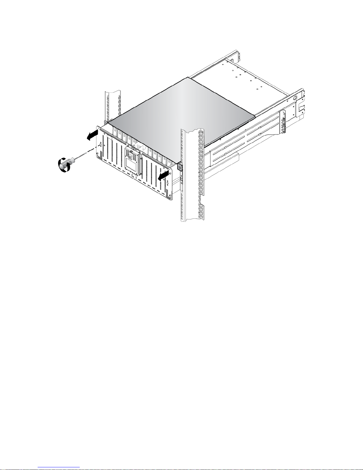
PS6500 Hardware Maintenance Basic Array Information
Figure 1-15: Opening the Chassis
2. Hold the chassis handles on the right side and the left side of the front panel and pull the chassis toward you,
exposing the disk drives.
To close and lock the chassis cover:
1. Slide the chassis completely into the rack.
Note: If the cover does not close completely, make sure the cam screws are turned counter-clockwise before
you slide the chassis into the rack.
2. Use a flathead screwdriver to turn the cam screws on the right side and left side of the front panel clockwise.
After you close and lock the chassis cover, you can install the bezel. See Removing and Installing the Bezel on
page 1-8.
Using the Cable Management System
The cable management system enables you to organize your power and network cables. It also enables you to open
the chassis cover without dislodging the cables.
Warning: For safety , you must use the cable management system to prevent pinching the cables and to reduce the
risk of electric shock.
The cable management system consists of two wire assemblies:
• One wire assembly has three arms, three clamps, and six fabric hook-and-loop fasteners.
• One wire assembly has one arm, two clamps, and three fabric hook-and-loop fasteners. See Figure 1-16.
1-10
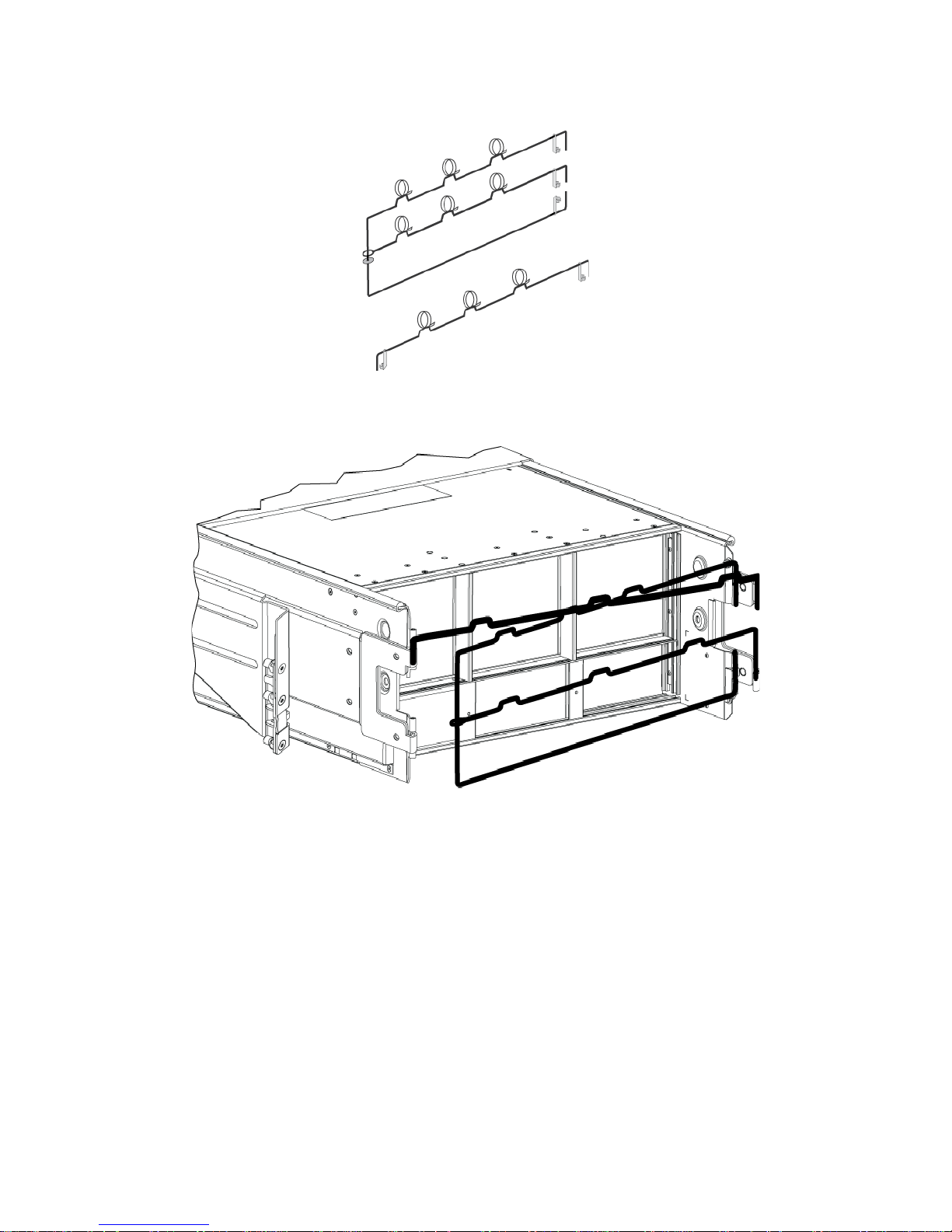
PS6500 Hardware Maintenance Basic Array Information
Figure 1-16: Cable Management System – Not Installed
The cable management system attaches to the rear of the array chassis and to the rack rails. See Figure 1-17.
Figure 1-17: Cable Management System – Installed
See the PS6500 Rack Mount Instructions for information about installing the cable management system.
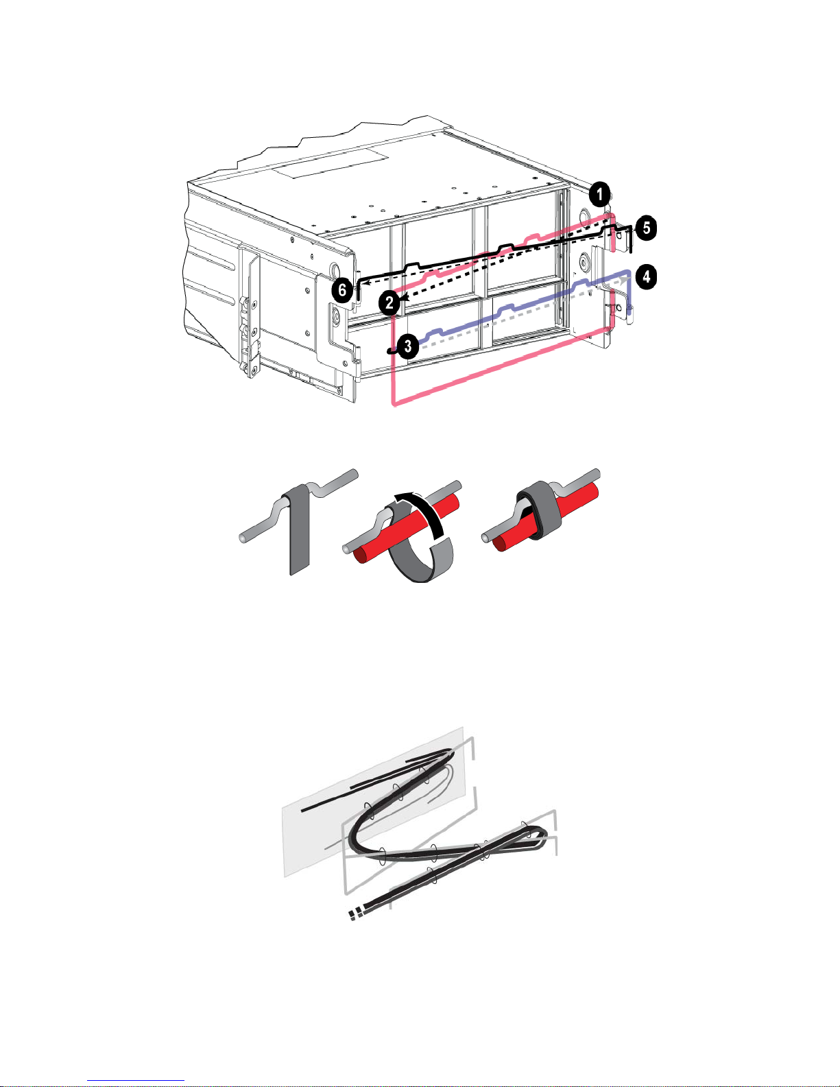
To use the cable management system:
1. Gather all the network and power cables and route the cables along the top arm of the three-arm assembly,
going fromcallout 1 to 2, as shown in Figure 1-18.
Make sure the cables have sufficient slack between the array back panel and the first connection to the cable
management system (callout 1 in Figure 1-18).
1-11
PS6500 Hardware Maintenance Basic Array Information
Figure 1-18: Routing Path on the Cable Management System
Connect all three fasteners on the arm and place the cables below the arms. See Figure 1-19.
Figure 1-19: Attaching the Hook-and-Loop Fasteners
2. Route the cables along the middle arm of the three-arm assembly, going from 3 to 4 in Figure 1-18.
3. Route the cables along the one-arm assembly (connected to the top of the left and right rails), going from 5 to 6
in Figure 1-18.
After routing the cables, the installation should resemble Figure 1-20.
Figure 1-20: Cables Attached to the Cable Management System
1-12

PS6500 Hardware Maintenance Basic Array Information
Turning on Power to an Array
There are two power modes for a PS6500 array:
• Standby mode. An array enter s standby mode if you turn of f power, but two or more functioning power supply
and cooling modules are connected to a source of power. In standby mode, the array is fully grounded, and
some array components are supplied with power. For example, the power button is lit and the LCD panel
displays “standby.” However, disks and control modules are not supplied with power, and the array is not
operational.
• Full-power mode. An array enters full-power mode when you push the power button on an array that is
currently in standby mode. All components and modules are supplied with power and the array becomes
operational.
To turn on power completely and restart an array:
1. Make sure three power supply and cooling modules are installed, and make sure at least two modules are
connected to a source of power, ideally on different circuits.
2. Remove the bezel, as described in Removing and Installing the Bezel on page 1-8.
3. Press the blue power button on the front panel.
When the array restart completes, if the array is a member of a group, the LCD panel will show the member name.
Shutting Down and Turning Off Power to an Array
Although a PS Series array includes hot-swappable hardware components, in some cases, you must cleanly shut
down the array and turn off power in order to perform maintenance.
Notes: When you shut down an array that is a member of a group, any volumes with data on the array will be set
offline until the array is restarted. This may affect initiators that are connected to the volumes.
Turning off power to an array will clear any messages on the LCD panel. Record any information shown in
the panel before turning off power.
To shut down and turn off power to an array:
1. Use one of the following procedures:
• Use telnet or SSH to connect to an IP address assigned to a functioning network interface on the array. Do
not connect to the group IP address.
• Use the serial cable shipped with the array to connect the serial port on the active control module (the ACT
LED will be green) to a console or a computer running a terminal emulator.
1-13
 Loading...