

Page 1

Dell Chassis Management Controller Version 3.0 for Dell
EMC PowerEdge VRTX
User's Guide
Page 2

Notes, cautions, and warnings
NOTE: A NOTE indicates important information that helps you make better use of your product.
CAUTION: A CAUTION indicates either potential damage to hardware or loss of data and tells you how to avoid the
problem.
WARNING: A WARNING indicates a potential for property damage, personal injury, or death.
Copyright © 2017 Dell Inc. or its subsidiaries. All rights reserved. Dell, EMC, and other trademarks are trademarks of Dell Inc. or its
subsidiaries. Other trademarks may be trademarks of their respective owners.
2017 - 09
Rev. A01
Page 3

Contents
1 Overview........................................................................................................................ 14
What is new in this release................................................................................................................................................15
Key Features..................................................................................................................................................................... 15
Management Features................................................................................................................................................15
Security Features........................................................................................................................................................16
Chassis Overview..............................................................................................................................................................16
Minimum CMC Version..................................................................................................................................................... 19
Supported Remote Access Connections........................................................................................................................... 19
Supported Platforms.........................................................................................................................................................19
Supported Web Browsers.................................................................................................................................................20
Managing Licenses ..........................................................................................................................................................20
Types of Licenses.......................................................................................................................................................20
Acquiring Licenses......................................................................................................................................................20
License Operations.....................................................................................................................................................20
License Component State or Condition and Available Operations............................................................................... 21
Managing Licenses Using CMC Web Interface............................................................................................................21
Managing Licenses Using RACADM............................................................................................................................21
Licensable Features in CMC........................................................................................................................................21
Viewing Localized Versions of the CMC Web Interface.................................................................................................... 23
Supported Management Console Applications................................................................................................................. 23
How to use this Guide...................................................................................................................................................... 23
Other Documents You May Need.....................................................................................................................................23
Accessing documents from the Dell EMC support site..................................................................................................... 24
2 Installing and Setting Up CMC...................................................................................... 25
Before You Begin..............................................................................................................................................................25
Installing CMC Hardware..................................................................................................................................................25
Checklist To Set up Chassis........................................................................................................................................25
Basic CMC Network Connection................................................................................................................................26
Installing Remote Access Software on a Management Station.........................................................................................26
Installing RACADM on a Linux Management Station.................................................................................................. 26
Uninstalling RACADM From a Linux Management Station..........................................................................................26
Conguring a Web Browser.............................................................................................................................................. 27
Proxy Server...............................................................................................................................................................27
Microsoft Phishing Filter.............................................................................................................................................27
Certicate Revocation List Fetching...........................................................................................................................28
Downloading Files From CMC With Internet Explorer.................................................................................................28
Enabling Animations In Internet Explorer.....................................................................................................................28
Setting Up Initial Access to CMC..................................................................................................................................... 28
Conguring Initial CMC Network................................................................................................................................29
Interfaces and Protocols to Access CMC..........................................................................................................................31
3
Page 4

Launching CMC Using Other Systems Management Tools.........................................................................................33
Downloading and Updating CMC Firmware......................................................................................................................33
Setting Chassis Physical Location and Chassis Name.......................................................................................................33
Setting Chassis Physical Location and Chassis Name Using Web Interface................................................................33
Setting Chassis Physical Location and Chassis Name Using RACADM.......................................................................33
Setting Date and Time on CMC........................................................................................................................................33
Setting Date and Time on CMC Using CMC Web Interface........................................................................................34
Setting Date and Time on CMC Using RACADM........................................................................................................34
Conguring LEDs to Identify Components on the Chassis................................................................................................34
Conguring LED Blinking Using CMC Web Interface.................................................................................................. 34
Conguring LED Blinking Using RACADM.................................................................................................................. 34
Conguring CMC Properties............................................................................................................................................35
Conguring iDRAC Launch Method Using CMC Web Interface....................................................................................... 35
Conguring iDRAC Launch Method Using RACADM........................................................................................................35
Conguring Login Lockout Policy Attributes Using CMC Web Interface ..........................................................................35
Conguring Login Lockout Policy Attributes Using RACADM........................................................................................... 35
Understanding Redundant CMC Environment..................................................................................................................36
About Standby CMC..................................................................................................................................................36
CMC Failsafe Mode....................................................................................................................................................36
Active CMC Election Process.....................................................................................................................................37
Obtaining Health Status of Redundant CMC.............................................................................................................. 37
Conguring Front Panel....................................................................................................................................................37
Conguring Power Button.......................................................................................................................................... 37
Conguring LCD.........................................................................................................................................................37
Accessing a Server Using KVM.................................................................................................................................. 38
3 Logging in to CMC........................................................................................................ 39
Accessing CMC Web Interface.........................................................................................................................................39
Logging in to CMC as a Local User, Active Directory User, or LDAP User.........................................................................39
Logging in to CMC Using a Smart Card............................................................................................................................40
Logging in to CMC Using Single Sign-on...........................................................................................................................41
Logging In To CMC Using Serial, Telnet, Or SSH Console..................................................................................................41
Accessing CMC Using RACADM.......................................................................................................................................41
Logging in to CMC Using Public Key Authentication.........................................................................................................42
Multiple CMC Sessions.....................................................................................................................................................42
Changing Default Login Password.................................................................................................................................... 42
Changing Default Login Password Using Web Interface............................................................................................. 43
Changing Default Login Password Using RACADM.................................................................................................... 43
Enabling or Disabling Default Password Warning Message .............................................................................................. 43
Enabling or Disabling Default Password Warning Message Using Web Interface........................................................ 43
Enabling or Disabling Warning Message to Change Default Login Password Using RACADM.....................................43
Use case scenarios...........................................................................................................................................................44
Conversion of External Shared PERC 8 card High Availability to Non-High Availability Mode using Web Interface..... 44
Conversion of External Shared PERC 8 card Non-High Availability to High Availability Mode using Web Interface..... 44
Conversion of External Shared PERC 8 card High Availability to Non-High Availability Mode using RACADM............44
Conversion of External Shared PERC 8 card Non-High Availability to High Availability Mode using RACADM............45
4
Page 5

4 Updating Firmware........................................................................................................46
Downloading CMC Firmware............................................................................................................................................46
Viewing Currently Installed Firmware Versions..................................................................................................................46
Viewing Currently Installed Firmware Versions Using CMC Web Interface..................................................................46
Viewing Currently Installed Firmware Versions Using RACADM.................................................................................. 47
Updating the CMC Firmware............................................................................................................................................47
Signed CMC Firmware Image.....................................................................................................................................48
Updating CMC and Mainboard Firmware................................................................................................................... 48
Updating CMC Firmware Using Web Interface...........................................................................................................49
Updating CMC rmware using RACADM................................................................................................................... 49
Updating Chassis Infrastructure Firmware........................................................................................................................49
Updating Chassis Infrastructure Firmware Using CMC Web Interface........................................................................49
Updating Chassis Infrastructure Firmware Using RACADM........................................................................................50
Updating Server iDRAC Firmware.................................................................................................................................... 50
Updating Server iDRAC Firmware Using Web Interface............................................................................................. 50
Updating Server Component Firmware............................................................................................................................. 51
Server Component Update Sequence........................................................................................................................52
Enabling Lifecycle Controller.......................................................................................................................................52
Choosing Server Component Firmware Update Type Using CMC Web Interface.......................................................53
Filtering Components for Firmware Updates.............................................................................................................. 53
Viewing Firmware Inventory............................................................................................................................................. 54
Viewing Firmware Inventory Using CMC Web Interface............................................................................................. 54
Viewing Firmware Inventory Using RACADM............................................................................................................. 55
Saving Chassis Inventory Report Using CMC Web Interface............................................................................................56
Conguring Network Share Using CMC Web Interface....................................................................................................56
Lifecycle Controller Job Operations..................................................................................................................................56
Reinstalling Server Component Firmware................................................................................................................... 57
Rolling Back Server Component Firmware........................................................................................................................57
Rolling Back Server Component Firmware Using the CMC Web Interface................................................................. 57
Upgrading Server Component Firmware.......................................................................................................................... 58
Upgrading Server Component Firmware From File Using CMC Web Interface...........................................................58
Server Component Single Click Update Using Network Share................................................................................... 59
Pre-requisites for Using Network Share Update Mode...............................................................................................59
Upgrading Server Component Firmware From Network Share Using CMC Web Interface........................................ 59
Supported Firmware Versions for Server Component Update....................................................................................60
Deleting Scheduled Server Component Firmware Jobs.....................................................................................................61
Deleting Scheduled Server Component Firmware Jobs Using the Web Interface........................................................61
Updating Storage Component Using CMC Web Interface................................................................................................ 61
Recovering iDRAC Firmware Using CMC.......................................................................................................................... 61
5 Viewing Chassis Information and Monitoring Chassis and Component Health............... 62
Viewing Chassis and Component Summaries...................................................................................................................62
Chassis Graphics........................................................................................................................................................63
Selected Component Information...............................................................................................................................63
Viewing Server Model Name and Service Tag............................................................................................................66
5
Page 6

Viewing Chassis Summary................................................................................................................................................66
Viewing Chassis Controller Information and Status.......................................................................................................... 66
Viewing Information and Health Status of All Servers.......................................................................................................66
Viewing Health Status and Information for Individual Server............................................................................................ 66
Viewing Information and Health Status of the IOM...........................................................................................................67
Viewing Information and Health Status of Fans................................................................................................................ 67
Conguring Fans........................................................................................................................................................ 68
Viewing Front Panel Properties........................................................................................................................................ 68
Viewing KVM Information and Health Status....................................................................................................................68
Viewing LCD Information and Health................................................................................................................................69
Viewing Information and Health Status of Temperature Sensors......................................................................................69
Viewing Storage Capacity and Status of the Storage Components..................................................................................69
6 Conguring CMC...........................................................................................................71
Viewing and Modifying CMC Network LAN Settings........................................................................................................ 71
Viewing and Modifying CMC Network LAN Settings Using CMC Web Interface........................................................72
Viewing and Modifying CMC Network LAN Settings Using RACADM........................................................................72
Enabling the CMC Network Interface.........................................................................................................................72
Enabling or Disabling DHCP for the CMC Network Interface Address........................................................................73
Enabling or Disabling DHCP for DNS IP Addresses.....................................................................................................73
Setting Static DNS IP addresses................................................................................................................................ 73
Conguring IPv4 and IPv6 DNS Settings ...................................................................................................................73
Conguring Auto Negotiation, Duplex Mode, and Network Speed for IPv4 and IPv6..................................................74
Setting the Maximum Transmission Unit for IPv4 and IPv6.........................................................................................74
Conguring CMC Network and Login Security Settings................................................................................................... 74
Conguring IP Range Attributes Using CMC Web Interface ...................................................................................... 74
Conguring IP Range Attributes Using RACADM....................................................................................................... 75
Conguring Virtual LAN Tag Properties for CMC............................................................................................................. 75
Conguring Virtual LAN Tag Properties for CMC Using RACADM..............................................................................75
Conguring Virtual LAN Tag Properties for CMC Using Web Interface.......................................................................76
Federal Information Processing Standards........................................................................................................................76
Enabling FIPS Mode Using CMC Web Interface......................................................................................................... 77
Enabling FIPS Mode Using RACADM..........................................................................................................................77
Disabling FIPS Mode...................................................................................................................................................77
Conguring Services.........................................................................................................................................................77
Conguring Services Using CMC Web Interface........................................................................................................ 78
Conguring Services Using RACADM.........................................................................................................................78
Conguring CMC Extended Storage Card........................................................................................................................78
Setting Up Chassis Group.................................................................................................................................................79
Adding Members To Chassis Group............................................................................................................................79
Removing a Member from the Leader........................................................................................................................80
Disbanding a Chassis Group....................................................................................................................................... 80
Disabling an Individual Member at the Member Chassis............................................................................................. 80
Accessing the Web page of a Member Chassis or Server.......................................................................................... 80
Propagating Leader Chassis Properties to Member Chassis........................................................................................81
Server Inventory for MCM group................................................................................................................................ 81
6
Page 7

Saving Server Inventory Report.................................................................................................................................. 81
Chassis Group Inventory and Firmware Version..........................................................................................................82
Viewing Chassis Group Inventory .............................................................................................................................. 83
Viewing Selected Chassis Inventory Using Web Interface...........................................................................................83
Viewing Selected Server Component Firmware Versions Using Web Interface...........................................................83
Chassis Conguration Proles.......................................................................................................................................... 83
Saving Chassis Conguration..................................................................................................................................... 83
Restoring Chassis Conguration Prole......................................................................................................................84
Viewing Stored Chassis Conguration Proles........................................................................................................... 84
Applying Chassis Conguration Proles......................................................................................................................84
Exporting Chassis Conguration Proles.................................................................................................................... 85
Editing Chassis Conguration Proles........................................................................................................................ 85
Deleting Chassis Conguration Proles...................................................................................................................... 85
Conguring Multiple CMCs Using RACADM.................................................................................................................... 85
Creating a CMC Conguration File............................................................................................................................. 86
Parsing Rules..............................................................................................................................................................87
Modifying the CMC IP Address..................................................................................................................................88
Conguring Multiple CMCs through RACADM Using Chassis Conguration Proles........................................................88
Exporting Chassis Conguration proles.................................................................................................................... 89
Importing Chassis Conguration proles.................................................................................................................... 89
Parsing Rules..............................................................................................................................................................89
Viewing and Ending CMC Sessions..................................................................................................................................90
Viewing and Ending CMC Sessions Using Web Interface........................................................................................... 90
Viewing and Ending CMC Sessions Using RACADM.................................................................................................. 90
7 Conguring Servers.......................................................................................................91
Conguring Slot Names.................................................................................................................................................... 91
Conguring iDRAC Network Settings...............................................................................................................................92
Conguring iDRAC QuickDeploy Network Settings.................................................................................................... 92
Assigning QuickDeploy IP Address to Servers............................................................................................................ 94
Modifying iDRAC Network Settings for Individual Server iDRAC................................................................................94
Modifying iDRAC Network Settings Using RACADM..................................................................................................94
Conguring iDRAC Virtual LAN Tag Settings....................................................................................................................95
Conguring iDRAC Virtual LAN Tag Settings Using RACADM.................................................................................... 95
Conguring iDRAC Virtual LAN Tag Settings Using Web Interface.............................................................................95
Setting First Boot Device.................................................................................................................................................95
Setting First Boot Device For Multiple Servers Using CMC Web Interface.................................................................96
Setting First Boot Device For Individual Server Using CMC Web Interface................................................................ 96
Setting First Boot Device Using RACADM................................................................................................................. 96
Conguring Server FlexAddress........................................................................................................................................97
Conguring Remote File Share......................................................................................................................................... 97
Conguring Prole Settings Using Server Conguration Replication.................................................................................97
Accessing Server Proles Page.................................................................................................................................. 98
Adding or Saving Prole.............................................................................................................................................98
Applying Prole.......................................................................................................................................................... 99
Importing Prole.........................................................................................................................................................99
7
Page 8

Exporting Prole.........................................................................................................................................................99
Editing Prole........................................................................................................................................................... 100
Deleting Prole......................................................................................................................................................... 100
Viewing Prole Settings............................................................................................................................................100
Viewing Stored Prole Settings................................................................................................................................. 101
Viewing Prole Log.................................................................................................................................................... 101
Completion Status And Troubleshooting....................................................................................................................101
Quick Deploy of Proles.............................................................................................................................................101
Assigning Server Proles to Slots ............................................................................................................................. 101
Boot Identity Proles................................................................................................................................................ 102
Saving Boot Identity Proles..................................................................................................................................... 102
Applying Boot Identity Proles..................................................................................................................................103
Clearing Boot Identity Proles...................................................................................................................................104
Viewing Stored Boot Identity Proles........................................................................................................................104
Importing Boot Identity Proles................................................................................................................................ 104
Exporting Boot Identity Proles................................................................................................................................ 104
Deleting Boot Identity Proles...................................................................................................................................104
Managing Virtual MAC Address Pool........................................................................................................................ 105
Creating MAC Pool................................................................................................................................................... 105
Adding MAC Addresses............................................................................................................................................105
Removing MAC Addresses....................................................................................................................................... 105
Deactivating MAC Addresses....................................................................................................................................106
Launching iDRAC using Single Sign-On.................................................................................................................... 106
Launching Remote Console.......................................................................................................................................107
8 Conguring CMC To Send Alerts................................................................................. 108
Enabling Or Disabling Alerts............................................................................................................................................ 108
Enabling Or Disabling Alerts Using CMC Web Interface............................................................................................ 108
Filtering Alerts...........................................................................................................................................................108
Conguring Alert Destinations........................................................................................................................................ 109
Conguring SNMP Trap Alert Destinations...............................................................................................................109
Conguring Email Alert Settings................................................................................................................................ 110
9 Conguring User Accounts and Privileges....................................................................112
Types of Users.................................................................................................................................................................112
Modifying Root User Administrator Account Settings......................................................................................................115
Conguring Local Users...................................................................................................................................................115
Conguring Local Users Using CMC Web Interface...................................................................................................115
Congure Local Users Using RACADM......................................................................................................................116
Conguring Active Directory Users.................................................................................................................................. 117
Supported Active Directory Authentication Mechanisms........................................................................................... 117
Standard Schema Active Directory Overview............................................................................................................ 117
Conguring Standard Schema Active Directory.........................................................................................................118
Extended Schema Active Directory Overview...........................................................................................................120
Conguring Extended Schema Active Directory........................................................................................................ 121
Conguring Generic LDAP Users.................................................................................................................................... 128
8
Page 9

Conguring the Generic LDAP Directory to Access CMC......................................................................................... 128
Conguring Generic LDAP Directory Service Using CMC Web Interface.................................................................. 128
Conguring Generic LDAP Directory Service Using RACADM.................................................................................. 129
10 Conguring CMC For Single Sign-On Or Smart Card Login........................................130
System Requirements..................................................................................................................................................... 130
Client Systems..........................................................................................................................................................130
CMC.........................................................................................................................................................................130
Prerequisites For Single Sign-On Or Smart Card Login.................................................................................................... 131
Generating Kerberos Keytab File......................................................................................................................................131
Conguring CMC For Active Directory Schema...............................................................................................................131
Conguring Browser For SSO Login................................................................................................................................ 131
Internet Explorer........................................................................................................................................................131
Mozilla Firefox ..........................................................................................................................................................132
Conguring Browser For Smart Card Login.....................................................................................................................132
Conguring CMC SSO Or Smart Card Login For Active Directory Users........................................................................132
Conguring CMC SSO Or Smart Card Login For Active Directory Users Using Web Interface................................. 132
Uploading Keytab File................................................................................................................................................132
Conguring CMC SSO Or Smart Card Login For Active Directory Users Using RACADM........................................ 133
11 Conguring CMC to Use Command Line Consoles......................................................134
CMC Command Line Console Features.......................................................................................................................... 134
CMC Command Line Interface Commands...............................................................................................................134
Using Telnet Console With CMC.....................................................................................................................................134
Using SSH With CMC...............................................................................................................................................135
Supported SSH Cryptography Schemes................................................................................................................... 135
Congure Public Key Authentication Over SSH........................................................................................................ 135
Conguring Terminal Emulation Software........................................................................................................................137
Conguring Linux Minicom........................................................................................................................................137
Connecting to Servers or Input Output Module Using Connect Command.....................................................................138
Conguring the Managed Server BIOS for Serial Console Redirection......................................................................139
Conguring Windows for Serial Console Redirection.................................................................................................140
Conguring Linux for Server Serial Console Redirection During Boot........................................................................140
Conguring Linux for Server Serial Console Redirection After Boot...........................................................................141
12 Using FlexAddress and FlexAdress Plus...................................................................... 143
About FlexAddress..........................................................................................................................................................143
About FlexAddress Plus............................................................................................................................................ 143
Viewing FlexAddress Activation Status..................................................................................................................... 144
Conguring FlexAddress.................................................................................................................................................145
Conguring FlexAddress for Chassis-Level Fabric and Slots..................................................................................... 145
Viewing World Wide Name or Media Access Control Addresses..................................................................................... 146
Fabric Conguration................................................................................................................................................. 146
Viewing WWN or MAC Address Information...................................................................................................................146
Viewing Basic WWN or MAC Address Information Using Web Interface......................................................................... 147
Viewing Advanced WWN or MAC Address Information Using Web Interface..................................................................148
9
Page 10

Viewing WWN or MAC Address Information Using RACADM......................................................................................... 148
Command Messages...................................................................................................................................................... 149
FlexAddress DELL SOFTWARE LICENSE AGREEMENT................................................................................................ 150
13 Managing Fabrics....................................................................................................... 152
Fresh Power-up Scenario................................................................................................................................................152
Monitoring IOM Health................................................................................................................................................... 152
Conguring Network Settings for IOM........................................................................................................................... 152
Conguring Network Settings for IOM Using CMC Web Interface........................................................................... 152
Conguring Network Settings for IOM Using RACADM............................................................................................153
Managing Power Control Operation for IOMs.................................................................................................................153
Enabling or Disabling LED Blinking for IOMs....................................................................................................................153
14 Managing and Monitoring Power................................................................................ 154
Redundancy Policies.......................................................................................................................................................154
Grid Redundancy Policy............................................................................................................................................154
Power Supply Redundancy Policy............................................................................................................................. 155
Dynamic Power Supply Engagement..............................................................................................................................155
Default Redundancy Conguration................................................................................................................................. 156
Grid Redundancy...................................................................................................................................................... 156
Power Supply Redundancy.......................................................................................................................................156
Power Budgeting For Hardware Modules....................................................................................................................... 156
Server Slot Power Priority Settings.................................................................................................................................157
Assigning Priority Levels To Servers................................................................................................................................158
Assigning Priority Levels To Servers Using CMC Web Interface......................................................................................158
Assigning Priority Levels To Servers Using RACADM......................................................................................................158
Viewing Power Consumption Status...............................................................................................................................158
Viewing Power Consumption Status Using CMC Web Interface...............................................................................158
Viewing Power Consumption Status Using RACADM...............................................................................................158
AC Power Recovery..................................................................................................................................................159
Viewing Power Budget Status Using CMC Web Interface.............................................................................................. 159
Viewing Power Budget Status Using RACADM........................................................................................................ 159
Redundancy Status and Overall Power Health................................................................................................................159
Power Management After PSU Failure..................................................................................................................... 159
Power Management After Removing PSU................................................................................................................159
New Server Engagement Policy............................................................................................................................... 160
Power Supply and Redundancy Policy Changes in System Event Log...................................................................... 160
Conguring power budget and redundancy..................................................................................................................... 161
Power Conservation and Power Budget....................................................................................................................161
Maximum Power Conservation Mode.......................................................................................................................162
Server Power Reduction to Maintain Power Budget.................................................................................................162
110V PSUs AC Operation.......................................................................................................................................... 162
Remote Logging........................................................................................................................................................162
External Power Management....................................................................................................................................162
Conguring Power Budget and Redundancy Using CMC Web Interface...................................................................163
Conguring Power Budget and Redundancy Using RACADM...................................................................................163
10
Page 11

Executing Power Control Operations.............................................................................................................................. 164
Executing Power Control Operations on the Chassis................................................................................................ 164
Executing Power Control Operations on the Chassis Using Web Interface............................................................... 165
Executing Power Control Operations on the Chassis Using RACADM...................................................................... 165
Executing Power Control Operations on a Server...........................................................................................................165
Executing Power Control Operations for Multiple Servers Using CMC Web Interface....................................................165
Executing Power Control Operations on the IOM........................................................................................................... 166
Executing Power Control Operations on IOM Using CMC Web Interface................................................................. 166
Executing Power Control Operations on the IOM Using RACADM........................................................................... 166
15 Managing Chassis Storage......................................................................................... 167
Viewing Status of the Storage Components................................................................................................................... 167
Viewing the Storage Topology.........................................................................................................................................167
Viewing Fault-tolerant Troubleshooting Information of SPERC Using CMC Web Interface............................................. 168
Assigning Virtual Adapters To Slots Using CMC Web Interface.......................................................................................168
Fault-Tolerance in Storage Controllers.............................................................................................................................169
Security Key Mismatch................................................................................................................................................... 170
Resolving Security Key Mismatch Using CMC Web Interface...................................................................................170
Viewing Controller Properties Using CMC Web Interface................................................................................................170
Viewing Controller Properties Using RACADM.................................................................................................................171
Importing or Clearing Foreign Conguration...............................................................................................................171
Conguring Storage Controller Settings...........................................................................................................................171
Conguring Storage Controller Settings Using CMC Web Interface.......................................................................... 171
Conguring Storage Controller Settings Using RACADM..........................................................................................172
Shared PERC Controllers................................................................................................................................................ 172
Enabling or Disabling RAID Controller Using CMC Web Interface....................................................................................172
Enabling or Disabling RAID Controller Using RACADM.................................................................................................... 174
Enabling or disabling fault tolerance of external RAID controller using RACADM.............................................................174
Viewing Physical Disk Properties Using the CMC Web Interface.....................................................................................174
Viewing Physical Disk Drives Properties Using RACADM................................................................................................ 175
Identifying Physical Disks and Virtual Disks..................................................................................................................... 175
Assigning Global Hot Spares Using CMC Web Interface................................................................................................. 175
Assigning Global Hot Spares Using RACADM..................................................................................................................175
Recovering Physical Disks...............................................................................................................................................175
Viewing Virtual Disk Properties Using CMC Web Interface............................................................................................. 175
Viewing Virtual Disk Properties Using RACADM..............................................................................................................175
Creating Virtual Disk Using CMC Web Interface..............................................................................................................176
Managing Encryption Keys..............................................................................................................................................176
Creating Encryption Key Using CMC Web Interface................................................................................................. 176
Creating Encryption Key Using RACADM..................................................................................................................176
Modifying Encryption Key Identier Using CMC Web Interface.................................................................................177
Modifying Encryption Identier Key Using RACADM.................................................................................................177
Deleting Encryption Key Using CMC Web Interface..................................................................................................177
Deleting Encryption Key Using RACADM.................................................................................................................. 177
Encrypting Virtual Disks...................................................................................................................................................177
Encrypting Virtual Disks Using CMC Web Interface.................................................................................................. 177
11
Page 12

Encrypting Virtual Disks Using RACADM...................................................................................................................178
Unlocking Foreign Conguration..................................................................................................................................... 178
Unlocking Foreign Conguration Using CMC Web Interface..................................................................................... 178
Unlocking Foreign Conguration Using RACADM......................................................................................................178
Cryptographic Erase....................................................................................................................................................... 179
Performing Cryptographic Erase............................................................................................................................... 179
Applying Virtual Adapter Access Policy To Virtual Disks...................................................................................................179
Modifying Virtual Disk Properties Using CMC Web Interface.......................................................................................... 179
Enclosure Management Module......................................................................................................................................180
Viewing EMM Status and attributes......................................................................................................................... 180
Viewing Enclosure Status and Attributes.................................................................................................................. 180
Reporting up to two Enclosures per Connector......................................................................................................... 181
Setting Asset Tag and Asset Name of the Enclosure................................................................................................. 181
Viewing Temperature Probe Status and attributes of the Enclosure.......................................................................... 181
Setting the Temperature Warning Threshold of the Enclosure................................................................................... 181
Viewing Fan Status and attributes of the Enclosure..................................................................................................182
Viewing Enclosure Properties Using CMC Web Interface................................................................................................182
16 Managing PCIe Slots.................................................................................................. 183
Viewing PCIe Slot Properties Using CMC Web Interface................................................................................................ 183
Assigning PCIe Slots To Servers Using CMC Web Interface............................................................................................183
Managing PCIe Slots Using RACADM.............................................................................................................................184
PCIe Power Ride-Through...............................................................................................................................................184
Viewing PCIe Ride-through Properties Using CMC Web Interface............................................................................185
Viewing PCIe Ridethrough Properties Status Using RACADM..................................................................................185
Conguring PCIe Ride-through Properties Using CMC Web Interface......................................................................185
Conguring PCIe Ride-through Properties Status Using RACADM...........................................................................185
17 Troubleshooting and Recovery.................................................................................... 187
Resetting Forgotten Administrative Password.................................................................................................................187
Gathering Conguration Information, Chassis Status, and Logs Using RACDUMP..........................................................187
Supported Interfaces................................................................................................................................................188
Downloading SNMP Management Information Base File..........................................................................................188
First Steps to Troubleshoot a Remote System................................................................................................................ 188
Power Troubleshooting............................................................................................................................................. 189
Troubleshooting Alerts.................................................................................................................................................... 190
Viewing Event Logs........................................................................................................................................................ 190
Viewing Hardware Log..............................................................................................................................................190
Viewing Chassis Log..................................................................................................................................................191
Using Diagnostic Console................................................................................................................................................ 191
Resetting Components....................................................................................................................................................191
Saving or Restoring Chassis Conguration......................................................................................................................192
Troubleshooting Network Time Protocol Errors...............................................................................................................192
Interpreting LED Colors and Blinking Patterns.................................................................................................................193
Troubleshooting Non-responsive CMC............................................................................................................................194
Observing LEDs to Isolate the Problem.....................................................................................................................194
12
Page 13

Obtain Recovery Information from DB-9 Serial Port................................................................................................. 195
Recovering Firmware Image......................................................................................................................................195
Troubleshooting Network Problems................................................................................................................................ 196
Troubleshooting Controller..............................................................................................................................................196
Hotplugging enclosures in fault-tolerant chassis............................................................................................................. 196
18 Using LCD Panel Interface..........................................................................................198
LCD Navigation...............................................................................................................................................................198
Main Menu............................................................................................................................................................... 199
KVM Mapping Menu.................................................................................................................................................199
DVD Mapping........................................................................................................................................................... 199
Enclosure Menu........................................................................................................................................................199
IP Summary Menu................................................................................................................................................... 200
Settings................................................................................................................................................................... 200
Diagnostics.................................................................................................................................................................... 200
Front Panel LCD Messages.............................................................................................................................................201
LCD Module and Server Status Information....................................................................................................................201
19 Frequently Asked Questions...................................................................................... 205
RACADM....................................................................................................................................................................... 205
Managing and Recovering a Remote System.................................................................................................................205
................................................................................................................................................................................ 206
Active Directory............................................................................................................................................................. 206
FlexAddress and FlexAddressPlus...................................................................................................................................207
IOM................................................................................................................................................................................208
13
Page 14

1
Overview
The Dell Chassis Management Controller (CMC) for Dell EMC PowerEdge VRTX is a Systems Management hardware and software
solution for managing the PowerEdge VRTX chassis. The CMC has its own microprocessor and memory and is powered by the
modular chassis into which it is plugged.
CMC enables an IT administrator to:
• View inventory
• Perform conguration and monitoring tasks
• Remotely turn on and turn o chassis and servers
• Enable alerts for events on servers and components in the server module
• View and manage storage controller and hard disk drives in the VRTX chassis
• Manage the PCIe subsystem in the VRTX chassis
• Provide a one–many management interface to the iDRACs and I/O modules in the chassis
You can congure the PowerEdge VRTX chassis either with a single CMC, or with redundant CMCs. In redundant CMC
congurations, if the primary CMC loses communication with the chassis or the management network, a standby CMC takes over
the chassis management.
CMC provides multiple System Management functions for servers. Power and thermal management are the primary functions of
CMC, which are listed as follows:
• Enclosure-level real-time automatic power and thermal management.
– CMC monitors system power requirements and supports the optional Dynamic Power Supply Engagement (DPSE) mode.
This mode enables CMC to improve power eciency by setting the power supplies while the server in standby mode and
dynamically managing the load and redundancy requirements.
– CMC reports real-time power consumption, which includes logging high and low points with a time stamp.
– CMC supports setting an optional enclosure maximum power limit (System Input Power Cap), which alerts and takes actions
such as limiting the power consumption of servers, and/or preventing the turning on of new servers to keep the enclosure
under the dened maximum power limit.
– CMC monitors and automatically controls the functions of cooling fans and blowers on the basis of actual ambient and
internal temperature measurements.
– CMC provides comprehensive enclosure inventory and status or error reporting.
• CMC provides a mechanism for centralized conguration of the:
– Network and security setting of the Dell PowerEdge VRTX enclosure.
– Power redundancy and power ceiling settings.
– I/O switch and iDRAC network settings.
– First boot device on the server module.
– I/O fabric consistency checks between the I/O module and servers. CMC also disables components, if required, to protect
the system hardware.
– User access security.
– Storage components, including the fault-tolerant mode for the storage controllers.
– PCIe slots.
You can congure CMC to send email alerts or SNMP trap alerts for warnings or errors such as temperature, hardware
misconguration, power outage, fan speed, and blowers.
14
Page 15

What is new in this release
This release of CMC for Dell EMC PowerEdge VRTX supports:
• Displaying fan speed and temperature information using WSMan.
• Integrating the LLDP opensource daemon to forward the LLDP packets to iDRAC through VLAN.
• Transferring CMC dumplogs to iDRAC.
• Unlocking secure foreign conguration using the CMC web interface.
• Displaying wear gauge details of Solid State Drives (SSDs).
Key Features
The CMC features are grouped into management and security features.
Management Features
CMC provides the following management features:
• Redundant CMC environment.
• Dynamic Domain Name System (DDNS) registration for IPv4 and IPv6.
• Login management and conguration for local users, Active Directory, and LDAP.
• Advanced cooling options such and ECM (Enhanced Cooling Mode) and Fan Oset can be enabled to provide additional cooling
for improved performance.
• Remote system management and monitoring using SNMP, a web interface, KVM, Telnet, or SSH connection.
• Monitoring — Provides access to system information and status of components.
• Access to system event logs — Provides access to the hardware log and chassis log.
• Firmware updates for various chassis components — Enables you to update the rmware for CMC, iDRAC on servers, chassis
infrastructure, and chassis storage.
• Firmware update of server components such as BIOS, network controllers, storage controllers, and so on across multiple servers
in the chassis using Lifecycle Controller.
• Dell OpenManage software integration — Enables you to launch the CMC web interface from Dell OpenManage Server
Administrator or OpenManage Essentials (OME) 1.2.
• CMC alert — Alerts you about potential managed node issues through Remote syslog email message or SNMP trap.
• Remote power management — Provides remote power management functions, such as turn o and reset of any chassis
component, from a management console.
• Power usage reporting.
• Secure Sockets Layer (SSL) encryption — Provides secure remote system management through the web interface.
• Launch point for the Integrated Dell Remote Access Controller (iDRAC) web interface.
• Support for WS-Management.
• FlexAddress feature — Replaces the factory-assigned World Wide Name/Media Access Control (WWN/MAC) addresses with
chassis-assigned WWN/MAC addresses for a particular slot.
• iDRAC I/O Identity feature support for enhanced WWN/MAC Address Inventory.
• Graphical display of chassis component status and health.
• Support for single and multi-slot servers.
• LCD iDRAC conguration wizard supports for iDRAC network conguration.
• iDRAC single sign-on.
• Network time protocol (NTP) support.
• Enhanced server summary, power reporting, and power control pages.
• Forced CMC failover and virtual reseat of servers.
• Multi-chassis management, allows up to eight other chassis to be visible from the lead chassis.
15
Page 16
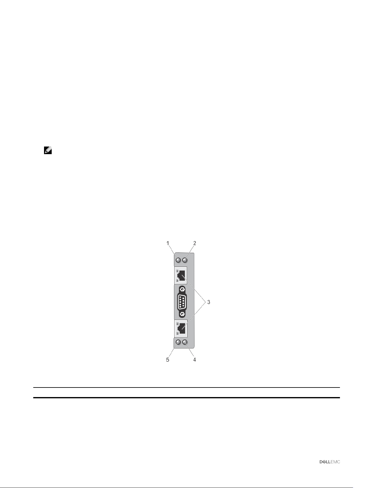
• Congure storage components on the chassis.
• Map PCIe slots to the servers and their identication.
Security Features
The CMC provides the following security features:
• Password-level security management — Prevents unauthorized access to a remote system.
• Centralized user authentication through:
– Active Directory using Standard Schema or an Extended Schema (optional).
– Hardware-stored user IDs and passwords.
• Role-based authority — Enables an administrator to congure specic privileges for each user.
• User ID and password conguration through the web interface. Web interface supports 128-bit SSL 3.0 encryption and 40-bit
SSL 3.0 encryption (for countries where 128-bit is not acceptable).
NOTE: Telnet does not support SSL encryption.
• Congurable IP ports (if applicable).
• Login failure limits per IP address, with login blocking from the IP address when the limit is exceeded.
• Congurable session auto time out, and more than one simultaneous sessions.
• Limited IP address range for clients connecting to CMC.
• Secure Shell (SSH), which uses an encrypted layer for higher security.
• Single Sign-on, Two-Factor Authentication, and Public Key Authentication.
Chassis Overview
The gure here shows a view of the CMC connectors.
Figure 1. CMC connectors and LEDs
Table 1. CMC connectors and LEDs
Item Indicator, Button, or Connector
1 Status/identication indicator (CMC 1)
2 Power indicator (CMC 1)
3 CMC connector ports (2)
4 Power indicator (CMC 2)
16
Page 17
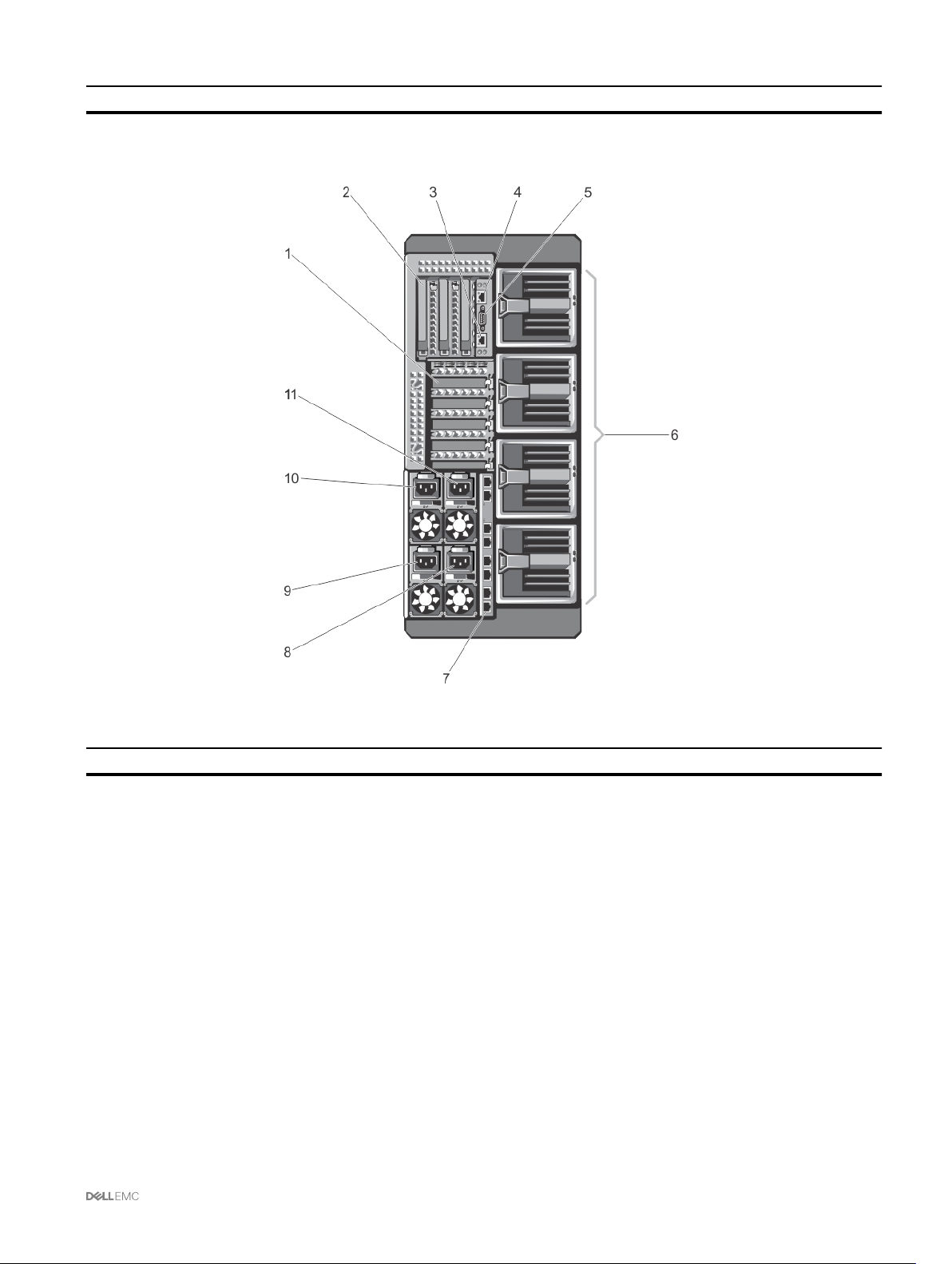
Item Indicator, Button, or Connector
5 Status/identication indicator (CMC 2)
A Back Panel view of the chassis is given here with a table that lists the parts and devices available in the CMC.
Figure 2. CMC back panel
Table 2. CMC back panel — parts
Item Indicator, Button, or Connector
1 PCIe expansion card slots low-prole (5)
2 PCIe expansion card slots full height (3)
3 CMC GB Ethernet port (CMC-2)
4 CMC GB Ethernet port (CMC-1)
5 Serial Connector
6 Blower modules (4)
7 I/O module ports
8 PSU 4
9 PSU 3
10 PSU 1
11 PSU 2
A Front Panel view of the chassis is given here with a table that lists the parts and devices available in the CMC.
17
Page 18
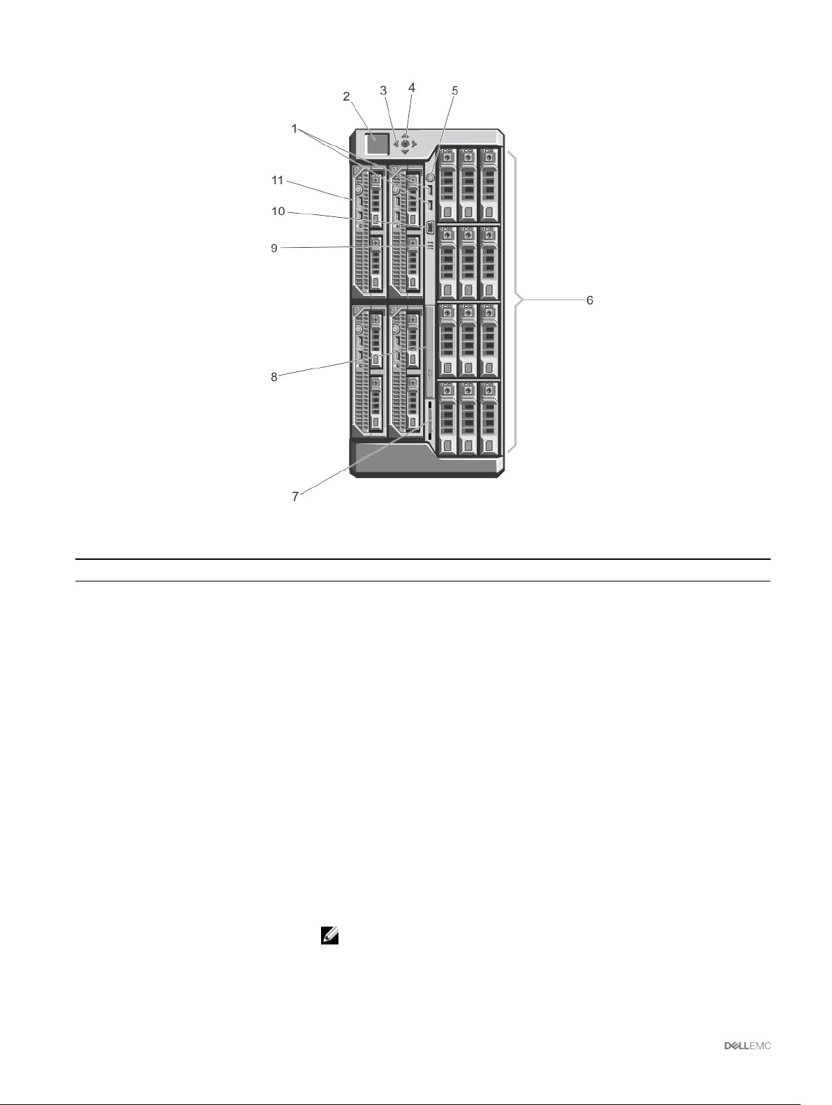
Figure 3. Front-Panel Features And Indicators—3.5 Inch Hard Disk Drive Chassis
Table 3. Front panel — features and indicators
Item Indicator, Button, or Connector Description
1 USB connectors (2) Allows a keyboard and mouse to be connected to the system.
2 LCD panel Provides system information and status, and error messages to indicate when the
system is operating correctly or when the system needs attention.
3 LCD menu scroll buttons (4) Moves the cursor in one-step increments.
4 Selection ("check") button Selects and saves an item on the LCD screen and moves to the next screen.
5 Enclosure power-on indicator, power
button
6 Hard disk drives (HDD)
The power-on indicator glows when the enclosure power is on. The power button
controls the PSU output to the system.
2.5 inch hard drive
Up to twenty-ve 2.5 inch hot-swappable hard disk drives.
enclosure
3.5 inch hard drive
Up to twelve 3.5 inch hot-swappable hard disk drives.
enclosure
7 Information tag A slide-out label panel which allows you to record system information such as Service
Tag, NIC, MAC address, the system's electrical rating, and Worldwide Regulatory
Agency marks.
8 Optical drive (optional) One optional SATA DVD-ROM drive or DVD+/-RW drive.
9 Vents Vents for the temperature sensor.
NOTE: To make sure about proper cooling, verify that the vents are not
blocked.
10 Video connector Allows a monitor to be connected to the system.
18
Page 19

Item Indicator, Button, or Connector Description
11 Server modules Up to four PowerEdge M520, M620, M630, or M640 server modules or 2 M820
server modules congured for the enclosure.
Minimum CMC Version
The following table lists the minimum CMC version required to enable the listed server modules.
Table 4. Minimum CMC Version for server modules
Servers Minimum version of CMC
PowerEdge M520 CMC 1.36
PowerEdge M620 CMC 1.36
PowerEdge M820 CMC 1.36
PowerEdge M630 CMC 2.00
PowerEdge M830 CMC 2.00
PowerEdge M640 CMC 3.00
The following table lists the minimum CMC version required to enable the listed I/O moduless.
Table 5. Minimum CMC Version for I/O modules
IOM Switches Minimum version of CMC
R1 VRTX 1Gb Pass-through CMC 1.20
R1-2401 VRTX 1GbE Switch CMC 1.20
R1-2210 VRTX 10Gb Switch CMC 2.00
Supported Remote Access Connections
The following table lists the supported Remote Access Controllers.
Table 6. Supported Remote Access Connections
Connection Features
CMC Network Interface ports
Serial port
• GB port: Dedicated network interface for the CMC web interface.
• DHCP support.
• SNMP traps and e-mail event notication.
• Network interface for the iDRAC and I/O Modules (IOMs).
• Support for Telnet/SSH command console and RACADM CLI commands including
system boot, reset, power-on, and shutdown commands.
• Support for serial console and RACADM CLI commands including system boot, reset,
power-on, and shutdown commands.
• Support for binary interchange for applications designed to communicate with a binary
protocol to a particular type of I/O Module.
• Serial port can be connected internally to the serial console of a server, or I/O module,
using the connect (or racadm connect) command.
• Provides access only to the active CMC.
Supported Platforms
CMC supports modular servers designed for the PowerEdge VRTX platform. For information about compatibility with CMC, see the
documentation for your device.
19
Page 20

For the latest supported platforms, see the Dell Chassis Management Controller (CMC) Version 3.0 for Dell PowerEdge VRTX
Release Notes available at dell.com/support/manuals.
Supported Web Browsers
The following web browsers are supported for Dell PowerEdge VRTX:
• Microsoft Internet Explorer 9
• Microsoft Internet Explorer 10
• Microsoft Internet Explorer 11
• Microsoft EDGE
• Safari version 7
• Safari version 8
• Safari version 9
• Mozilla Firefox version 52
• Mozilla Firefox version 53
• Google Chrome version 57
• Google Chrome version 58
NOTE: By default, TLS 1.1 and TLS 1.2 are supported in this release. However, to enable TLS 1.0 use the following racadm
command:
$ racadm config -g cfgRacTuning -o cfgRacTuneTLSProtocolVersionEnable TLSv1.0+
Managing Licenses
The CMC features are available based on the license (CMC Express or CMC Enterprise) purchased. Only licensed features are
available in the interfaces that allow you to congure or use CMC. For example, CMC Web interface, RACADM, WS-MAN, and so
on. CMC license management and rmware update functionality is always available through CMC Web interface and RACADM.
Types of Licenses
The types of licenses oered are:
• 30 day evaluation and extension — The license expires after 30 days that can be extended for 30 days. Evaluation licenses are
duration-based, and the timer runs when power is applied to the system.
• Perpetual — The license is bound to the service tag and is permanent.
Acquiring Licenses
Use any of the following methods to acquire the licenses:
• E-mail — License is attached to an e-mail that is sent after requesting it from the technical support center.
• Self-service portal — A link to the Self-Service Portal is available from CMC. Click this link to open the licensing Self-Service
Portal on the internet from where you can purchase licenses. For more information, see the online help for the self-service portal
page.
• Point-of-sale — License is acquired while placing the order for a system.
License Operations
Before you perform the license management tasks, make sure to acquire the licenses. For more information, see the Overview and
Feature Guide available at support.dell.com.
You can perform the following licensing operations using CMC, RACADM, and WS-MAN for one-to-one license management, and
Dell License Manager for one-to-many license management:
20
Page 21

NOTE: If you have purchased a system with all the licenses pre-installed, then license management is not required.
• View — View the current license information.
• Import — After acquiring the license, store the license in a local storage and import it into CMC using one of the supported
interfaces. The license is imported if it passes the validation checks.
NOTE: For a few features, a CMC restart may be required to enable the features.
• Export — Export the installed license into an external storage device back up or to reinstall it after a service part is replaced. The
le name and format of the exported license is <EntitlementID>.xml
• Delete — Delete the license that is assigned to a component if the component is missing. After the license is deleted, it is not
stored in CMC and the base product functions are enabled.
• Replace — Replace the license to extend an evaluation license, change a license type such as an evaluation license with a
purchased license, or extend an expired license.
• An evaluation license may be replaced with an upgraded evaluation license or with a purchased license.
• A purchased license may be replaced with an updated license or with an upgraded license. For more information about license,
click Dell Software License Management Portal .
• Learn More — Learn more about an installed license, or the licenses available for a component installed in the server.
NOTE: For the Learn More option to display the correct page, make sure that *.dell.com is added to the list of Trusted
Sites in the Security Settings. For more information, see the Internet Explorer help documentation.
License Component State or Condition and Available Operations
The following table provides the list of license operations available based on the license state or condition.
Table 7. License Operations Based on State and Condition
License/Component
state or condition
Non-administrator login No Yes No No Yes
Active license Yes Yes Yes Yes Yes
Expired license No Yes Yes Yes Yes
License installed but
component missing
Import Export Delete Replace Learn More
No Yes Yes No Yes
Managing Licenses Using CMC Web Interface
To manage the licenses using the CMC Web interface, go to Chassis Overview → Setup → Licenses.
Before importing a license, make sure to store a valid license le on the local system or on a network share that is accessible from
the CMC. The license is either embedded, or sent through an email from the Self-Service Web Portal, or from the License Key
Management tool.
The Licensing page displays the licenses that are associated to devices, or the licenses that are installed, but the device is not
present in the system. For more information about importing, exporting, deleting, or replacing a license, see the Online Help.
Managing Licenses Using RACADM
To manage licenses using the RACADM commands, use the following license subcommand.
racadm license <license command type>
For more information about the RACADM commands, see the Chassis Management Controller for PowerEdge VRTX RACADM
Command Line Reference Guide available at dell.com/support/Manuals.
Licensable Features in CMC
A list of CMC features that are enabled on the basis of your license is given here in the table.
21
Page 22

Table 8. Licensable features
Feature Express Enterprise Notes
CMC Network Yes Yes
CMC Serial Port Yes Yes
RACADM (SSH, Local, and
Yes Yes
Remote)
CMC Setup Backup No Yes
CMC Setup Restore Yes Yes
WS-MAN Yes Yes
SNMP Yes Yes
Telnet Yes Yes
SSH Yes Yes
Web-based Interface Yes Yes
Email Alerts Yes Yes
LCD Deployment Yes Yes
Extended iDRAC Management Yes Yes
Remote Syslog No Yes
Directory Services No* Yes *For non-default directory service setting, only Reset Directory
Services is allowed with an Express license. Reset Directory
Services will set the Directory services to factory default.
iDRAC Single Sign-On No Yes
Two-Factor Authentication No Yes
PK Authentication No Yes
Remote File Share Yes Yes
Slot Resource Management No Yes
Enclosure-level power capping No* Yes *For non-default power cap setting, only Restore Power Cap is
allowed with an Express license. Restore Power Cap will reset the
Power Cap settings to factory default.
Dynamic Power Supply
Engagement
No* Yes *For non-default DPSE settings, only Restore DPSE is allowed with
an Express license. Restore DPSE will reset the DPSE to factory
default.
Multi-chassis management No Yes
Advanced Conguration No Yes
Enclosure-level backup No Yes
FlexAddress Enablement No* Yes *For non-default FlexAddress settings, only Restore Default is
allowed with Express license. Restore Default will reset the
FlexAddress settings to the factory default.
PCIe Adapter Mapping Yes* Yes *A maximum of two PCIe Adapters can be assigned per Server with
Express License.
Virtual Adapter to Slot
Mapping
No* Yes *For non-default mapping of Virtual Adapters, only Default mapping
is allowed with an Express license. Restore Default will change
virtual adapter mapping to factory default.
Virtual Adapter to Slot
Yes Yes
UnMapping
Server cloning No Yes
22
Page 23

Feature Express Enterprise Notes
One-to-many Server Firware
Update
One-to-many conguration for
iDRAC
Boot Identity No Yes
Chassis Prole No Yes
Quick Deploy No Yes
No Yes
No Yes
Viewing Localized Versions of the CMC Web Interface
To view localized versions of the CMC web interface, read through your web browser's documentations.
Supported Management Console Applications
CMC supports integration with Dell OpenManage Console. For more information, see the OpenManage Console documentation
available at dell.com/support/manuals.
How to use this Guide
The contents of this User's Guide enable you to perform the tasks by using:
• The Web interface: Only the task-related information is given here. For information about the elds and options, see the CMC for
Dell PowerEdge VRTX Online Help that you can open from the Web interface.
• The RACADM commands: The RACADM command or the object that you must use is provided here. For more information about
a RACADM command, see the Chassis Management Controller for PowerEdge VRTX RACADM Command Line Reference
Guide available at dell.com/cmcmanuals.
Other Documents You May Need
To access the documents from the Dell Support site. Along with this Reference Guide, you can access the following guides available
at dell.com/support/manuals.
• The VRTX CMC Online Help provides information about using the Web interface. To access the Online Help, click Help on the
CMC web interface.
• The Chassis Management Controller Version 3.0 for Dell PowerEdge VRTX RACADM Command Line Reference Guide provides
information about using the VRTX–related RACADM features.
• The Dell Chassis Management Controller (CMC) for Dell PowerEdge VRTX Version 3.0 Release Notes, available at dell.com/
cmcmanuals, provides last-minute updates to the system or documentation or advanced technical reference material intended
for experienced users or technicians.
• The Integrated Dell Remote Access Controller (iDRAC) User’s Guide provides information about installation, conguration, and
maintenance of the iDRAC on managed systems.
• The Dell OpenManage Server Administrator’s User’s Guide provides information about installing and using Server Administrator.
• The Dell OpenManage SNMP Reference Guide for iDRAC and Chassis Management Controller provides information about
SNMP MIBs.
• The Dell Update Packages User's Guide provides information about obtaining and using Dell Update Packages as part of your
system update strategy.
• The Dell Shared PowerEdge RAID Controller (PERC) 8 User's Guide provides information about deploying the Shared PERC 8
card and managing the storage subsystem. This document is available online at dell.com/storagecontrollermanuals.
• Dell systems management application documentation provides information about installing and using the systems management
software.
The following system documents provide more information about the system in which VRTX CMC is installed:
23
Page 24

• The safety instructions that came with your system provide important safety and regulatory information. For additional regulatory
information, see the Regulatory Compliance home page at www.dell.com/regulatory_compliance. Warranty information may be
included within this document or as a separate document.
• The Dell PowerEdge VRTX Getting Started Guide shipped with your system provides an overview of system features, setting up
your system, and technical specications.
• The setup placemat shipped with your system provides information about the initial system setup and conguration.
• The server module's Owner's Manual provides information about the server module's features and describes how to troubleshoot
the server module and install or replace the server module's components. This document is available online at dell.com/
poweredgemanuals.
• The rack documentation included with your rack solution describes how to install your system into a rack, if required.
• For the full name of an abbreviation or acronym used in this document, see the Glossary at dell.com/support/manuals.
• Systems management software documentation describes the features, requirements, installation, and basic operation of the
software.
• Documentation for any components you purchased separately provides information to congure and install these options.
• Any media that ships with your system that provides documentation and tools for conguring and managing your system,
including those pertaining to the operating system, system management software, system updates, and system components that
you purchased with your system. For more information on the system, scan the Quick Resource Locator (QRL) available on your
system and the system setup placemat that shipped with your system. Download the QRL application from your mobile platform
to enable the application on your mobile device.
Accessing documents from the Dell EMC support site
You can access the required documents using the following links:
• For Dell EMC Enterprise Systems Management documents — Dell.com/SoftwareSecurityManuals
• For Dell EMC OpenManage documents — Dell.com/OpenManageManuals
• For Dell EMC Remote Enterprise Systems Management documents — Dell.com/esmmanuals
• For iDRAC and Dell EMC Lifecycle Controller documents — Dell.com/idracmanuals
• For Dell EMC OpenManage Connections Enterprise Systems Management documents — Dell.com/
OMConnectionsEnterpriseSystemsManagement
• For Dell EMC Serviceability Tools documents — Dell.com/ServiceabilityTools
• For Client Command Suite Systems Management documents — Dell.com/DellClientCommandSuiteManuals
•
a. Go to Dell.com/Support/Home.
b. Click Choose from all products.
c. From All products section, click Software & Security, and then click the required link from the following:
– Enterprise Systems Management
– Remote Enterprise Systems Management
– Serviceability Tools
– Dell Client Command Suite
– Connections Client Systems Management
d. To view a document, click the required product version.
• Using search engines:
– Type the name and version of the document in the search box.
24
Page 25

Installing and Setting Up CMC
This section provides information about how to install your CMC hardware, establish access to CMC, congure your management
environment to use CMC, and guides you through the tasks for conguring a CMC:
• Set up initial access to CMC.
• Access CMC through a network.
• Add and congure CMC users.
• Update CMC rmware.
For more information about installing and setting up redundant CMC environments, see Understanding Redundant CMC
Environment.
Before You Begin
Before setting up your CMC environment, download the latest version of CMC rmware for PowerEdge VRTX from dell.com/
support/.
Also, make sure that you have the Dell Systems Management Tools and Documentation DVD that was included with your system.
Installing CMC Hardware
2
CMC is pre-installed on your chassis and hence no installation is required. You can install a second CMC to run as a standby to the
active CMC.
Checklist To Set up Chassis
The following tasks enable you to accurately set up the chassis:
1. CMC and the management station, where you use your browser, must be on the same network, which is called the
management network. Connect an Ethernet network cable from the CMC active port to the management network.
2. Install the I/O module in the chassis and connect the network cable to the chassis.
3. Insert the servers in the chassis.
4. Connect the chassis to the power source.
5. Press the power button, or turn on the chassis from the CMC web interface after completing the task in step 7.
NOTE: Do not turn on the servers.
6. Using the LCD panel, navigate to the IP Summary and click on the Check button to select. Use the IP address for the CMC in
the management system browser (IE, Chrome, or Mozilla). To set up DHCP for CMC, use LCD panel to, click Main Menu →
Settings → Network Settings.
7. Connect to the CMC IP address by using a web browser by typing the default username (root) and password (calvin).
8. Provide each iDRAC with an IP address in the CMC web interface, and enable the LAN and IPMI interface.
NOTE: iDRAC LAN interface on some servers are disabled by default. This information can be found on the CMC
web interface under
use the SetUp feature for each server).
9. Provide the IO module with an IP address in the CMC web interface. You can get the IP address by clicking I/O Module
Overview, and then clicking Setup.
10. Connect to each iDRAC through the Web browser and provide nal conguration of iDRAC. The default user name is root and
password is
calvin.
Server Overview → Setup. This might be an advanced license option; in which case you must
25
Page 26

11. Connect to the I/O module by using the web browser and provide nal conguration of the IO module.
12. Turn on the servers and install the operating system.
Basic CMC Network Connection
For the highest degree of redundancy, connect each available CMC to your management network.
Installing Remote Access Software on a Management Station
You can access CMC from a management station using remote access software, such as Telnet, Secure Shell (SSH), or serial
console utilities provided on your operating system or using the web interface.
To use remote RACADM from your management station, install remote RACADM using the Dell Systems Management Tools and
Documentation DVD that is available with your system. This DVD includes the following Dell OpenManage components:
• DVD root — Contains the Dell Systems Build and Update Utility.
• SYSMGMT — Contains the systems management software products including Dell OpenManage Server Administrator.
• Docs — Contains documentation for systems, systems management software products, peripherals, and RAID controllers.
• SERVICE — Contains the tools required to congure your system, and delivers the latest diagnostics and Dell-optimized drivers
for your system.
For information about installing Dell OpenManage software components, see the Dell OpenManage Installation and Security User's
Guide available on the DVD or at dell.com/support/manuals. You can also download the latest version of the Dell DRAC Tools from
support.dell.com.
Installing RACADM on a Linux Management Station
1. Log in as root to the system running a supported Red Hat Enterprise Linux or SUSE Linux Enterprise Server operating system
where you want to install the managed system components.
2. Insert the Dell Systems Management Tools and Documentation DVD into the DVD drive.
3. To mount the DVD to a required location, use the mount command or a similar command.
NOTE: On the Red Hat Enterprise Linux 5 operating system, DVDs are auto-mounted with the -noexec mount
option. This option does not allow you to run any executable from the DVD. You need to mount the DVD-ROM
manually, and then run the commands.
4. Navigate to the SYSMGMT/ManagementStation/linux/rac directory. To install the RAC software, type the following
command:
rpm -ivh *.rpm
5. For help about the RACADM command, type racadm help after you run the previous commands. For more information
about RACADM, see the
.
Guide
NOTE: When using the RACADM remote capability, you must have the 'write' permission on the folders where you
are using the RACADM subcommands, involving the le operations. For example, racadm getconfig -f <file
.
name>
Chassis Management Controller for Dell PowerEdge VRTX RACADM Command Line Reference
Uninstalling RACADM From a Linux Management Station
1. Log in as root to the system where you want to uninstall the management station features.
2. Run the following rpm query command to determine which version of the DRAC tools is installed:
rpm -qa | grep mgmtst-racadm
3. Verify the package version to be uninstalled and uninstall the feature by using the rpm -e rpm -qa | grep mgmtst-
racadm command.
26
Page 27

Conguring a Web Browser
You can congure and manage CMC, servers, and modules installed in the chassis through a web browser. See the “Supported
Browsers" section in the Dell Systems Software Support Matrix at dell.com/support/manuals.
The CMC and the management station where you use your browser must be on the same network, which is called the management
network. On the basis of your security requirements, the management network can be an isolated and highly secure network.
NOTE: Make sure that the security measures on the management network such as rewalls and proxy servers, do not
prevent your web browser from accessing the CMC.
Some browser features can interfere with connectivity or performance, especially if the management network does not have a route
to the Internet. If your management station is running on a Windows operating system, some Internet Explorer settings can interfere
with connectivity, even though you use a command line interface to access the management network.
NOTE: To address security issues, Microsoft Internet Explorer strictly monitors the time on its cookie management. To
support this, the time on your computer that runs Internet Explorer must be synchronized with the time on the CMC.
Proxy Server
To browse through a proxy server that does not have access to the management network, you can add the management network
addresses to the exception list of the browser. This instructs the browser to bypass the proxy server while accessing the
management network.
Internet Explorer
To edit the exception list in Internet Explorer:
1. Start Internet Explorer.
2. Click Tools → Internet Options → Connections.
3. In the Local Area Network (LAN) settings section, click LAN Settings.
4. In the Proxy server section, select the Use a proxy server for your LAN (These settings will not apply to dial-up or VPN
connections)
5. In the Exceptions section, add the addresses for CMCs and iDRACs on the management network to the semicolon-separated
list. You can use DNS names and wildcards in your entries.
option, and then click Advanced.
Mozilla FireFox
To edit the exception list in Mozilla Firefox version 19.0:
1. Start Mozilla Firefox.
2. Click Tools → Options (for systems running on Windows), or click Edit → Preferences (for systems running on Linux).
3. Click Advanced, and then click the Network tab.
4. Click Settings.
5. Select Manual Proxy Conguration.
6. In the No Proxy for eld, type the addresses for CMCs and iDRACs on the management network to the comma-separated list.
You can use DNS names and wildcards in your entries.
Microsoft Phishing Filter
If the Microsoft Phishing Filter is enabled in Internet Explorer on your management system, and your CMC does not have Internet
access, accessing CMC may be delayed by a few seconds. This delay can happen if you are using the browser or another interface
such as remote RACADM. To disable the phishing lter:
1. Start Internet Explorer.
2. Click Tools → Phishing Filter, and then click Phishing Filter Settings.
3. Select the Disable Phishing Filter option and click OK.
27
Page 28

Certicate Revocation List Fetching
If your CMC has no access to the Internet, disable the certicate revocation list (CRL) fetching feature in Internet Explorer. This
feature tests whether a server such as the CMC web server uses a certicate that is on a list of revoked certicates retrieved from
the Internet. If the Internet is inaccessible, this feature can cause delays of several seconds when you access the CMC using the
browser or with a command line interface such as remote RACADM.
To disable CRL fetching:
1. Start Internet Explorer.
2. Click Tools → Internet Options, and then click Advanced.
3. Go to the Security section, clear the Check for publisher’s certicate revocation option, and then click OK.
Downloading Files From CMC With Internet Explorer
When you use Internet Explorer to download les from the CMC, you may experience problems when the Do not save encrypted
pages to disk
To enable the Do not save encrypted pages to disk option:
1. Start Internet Explorer.
2. Click Tools → Internet Options → Advanced.
3. In the Security section, select the Do not save encrypted pages to disk option.
option is not enabled.
Enabling Animations In Internet Explorer
When transferring les to and from the web interface, a le transfer icon spins to show transfer activity. While using Internet
explorer, you have to congure the browser to play animations.
To congure Internet Explorer to play animations:
1. Start Internet Explorer.
2. Click Tools → Internet Options → Advanced.
3. Go to the Multimedia section, and then select the Play animations in web pages option.
Setting Up Initial Access to CMC
To remotely manage the CMC, connect the CMC to your management network, and then congure the CMC network settings.
NOTE: To manage the PowerEdge VRTX solution, it must be connected to your management network.
For information about conguring CMC network settings, see Conguring Initial CMC Network. This initial conguration assigns the
TCP/IP networking parameters that enable access to CMC.
CMC and iDRAC on each server and the network management ports for the switch I/O module are connected to a common
integrated network in the PowerEdge VRTX chassis. This allows the management network to be isolated from the server data
network. It is important to separate this trac for uninterrupted access to chassis management.
CMC is connected to the management network. All external access to CMC and iDRACs is achieved through CMC. Access to the
managed servers, conversely, is accomplished through network connections to the I/O module (IOM). This allows the application
network to be isolated from the management network.
It is recommended to isolate chassis management from the data network. Due to the potential of trac on the data network, the
management interfaces on the internal management network can be saturated by trac intended for servers. This results in CMC
and iDRAC communication delays. These delays may cause unpredictable chassis behavior, such as CMC displaying iDRAC as oine
even when it is up and running, which in turn causes other unwanted behavior. If physically isolating the management network is
impractical, the other option is to separate CMC and iDRAC trac to a separate VLAN. CMC and individual iDRAC network
interfaces can be congured to use a VLAN.
28
Page 29

Conguring Initial CMC Network
NOTE: Changing your CMC Network settings may disconnect your current network connection.
You can perform the initial network conguration of CMC before or after CMC has an IP address. If you congure CMC’s initial
network settings before you have an IP address, you can use either of the following interfaces:
• The LCD panel on the front of the chassis
• Dell CMC serial console
If you congure initial network settings after the CMC has an IP address, you can use any of the following interfaces:
• Command line interfaces (CLIs) such as a serial console, Telnet, SSH, or the Dell CMC console.
• Remote RACADM
• CMC web interface
• LCD Panel interface
CMC supports both IPv4 and IPv6 addressing modes. The conguration settings for IPv4 and IPv6 are independent of each other.
Conguring CMC Network Using LCD Panel Interface
You can use the LCD panel interface to set up the CMC network.
NOTE: You can customize the orientation of an LCD display (for rack or tower mode) by keeping the up-down buttons
pressed for two seconds. Alternately, you can also use the right-left buttons. For more information about the buttons
available on a CMC LCD panel, see LCD Navigation.
1. To start the CMC conguration:
• For a chassis that has not been congured earlier, the LCD Language panel is displayed. On the LCD Language panel,
navigate to the required language using the arrow buttons. When the desired language is highlighted, select the language by
pressing the Center button. The Network Settings panel is displayed.
• For a chassis that has been congured earlier, the Main Menu panel is displayed. From the Main Menu, select Settings and
then Network Settings.
2. On the Network Settings panel, select the required mode of setup:
• Quick Setup (DHCP) — Select this mode to set up CMC quickly using DHCP addresses. For information on conguring
CMC using this mode see Conguring CMC Using Quick Setup (DHCP).
• Advanced Setup — Select this mode to set up CMC for advanced congurations. For information on conguring CMC
using this mode see Conguring CMC Using Advanced Setup.
Conguring CMC Using Quick Setup (DHCP)
To set up a network using the LCD panel interface:
1. From the Network Settings panel, select Quick Setup (DHCP). The panel displays the following message.
About to get DHCP addresses. Ensure CMC network cable is connected.
2. Press the center button to highlight the accept button. Press the center button again to accept the settings or navigate to the
back arrow and the press the center button to go back and modify the settings.
Conguring CMC Using Advanced Setup
1. On the Network Settings panel, if you select Advanced Setup, the following message is displayed to conrm if want to
congure CMC:
Configure CMC?
2. To congure CMC by using advanced setup properties, click the center button selecting the check icon.
NOTE: To skip the CMC conguration navigate to the ‘X’ icon and then press the center button.
3. If you are asked to select an appropriate network speed, select a network speed (Auto (1Gb), 10Mb, or 100Mb) using
appropriate buttons.
29
Page 30

For eective network throughput, the network speed setting must match your network conguration. Setting the network
speed lower than the speed of your network conguration increases bandwidth consumption and slows down the network
communication. Determine whether or not your network supports the above network speeds and set it accordingly. If the
network conguration does not match any of these values, it is recommended to select the Auto (1 Gb) option, or refer to your
network equipment manufacturer's user documentation.
4. Perform one of the following tasks:
• Select Auto (1Gb), by pressing the center button, and then pressing the center button again. The Protocol panel is
displayed. Go to step 6.
• Select 10Mb, or 100Mb. The Duplex panel
is displayed. Go to step 5.
Else, if you
5. On the Duplex panel, to select the duplex mode (Full or Half) that matches the network environment, press the center button,
and then press the center button. The Protocol panel is displayed.
NOTE: The network speed and duplex mode settings are not available if Auto Negotiation is set to On, or if 1000MB
(1Gbps) is selected. If auto negotiation is turned on for one device but not the other, the device that is using auto
negotiation can determine the network speed of the other device, but not the duplex mode. In this case, half duplex
is selected as the duplex mode during auto negotiation. Such a duplex mismatch results in a slow network
connection.
6. On the Protocol panel, select an Internet Protocol (IPv4 Only, IPv6 Only, or Both) that you want to use for CMC, press the
center button, and then press the center button.
7.
• If you select IPv4 or Both, select DHCP or Static mode. Go to step 8.
• Else, if you select IPv6, the Congure iDRAC panel is displayed. Go to step 11 later in this procedure.
8. On the Mode panel, select the mode in which the CMC must obtain the NIC IP addresses. If you select DHCP, CMC retrieves
IP conguration (IP address, mask, and gateway) automatically from a DHCP server on your network. CMC is assigned a unique
IP address that is allotted on your network. If you select DHCP, press the center button, and then press the center again. The
Congure iDRAC panel is displayed. Go to step 11 later in this procedure.
9. If you select Static, enter the IP address, gateway, and subnet mask by following the instructions on the LCD panel.
The IP information that you entered is displayed. Press the center button, and then press the center button again. The CMC
Conguration screen lists the Static IP Address, Subnet Mask, and Gateway settings you entered. Check the settings for
accuracy. To correct a setting, press appropriate buttons. Press the center button, and then press the center button. The
Register DNS? panel is displayed.
10. To register select the check icon and press the center button. Set the DNS IP address, select the check icon, and then press
the center button. If DNS registration is not required, then select the ‘X’ icon and press the center button.
11. Indicate whether or not you want to congure iDRAC:
• No: Select the ‘X’ icon then press the center button. Go to step 17 later in this procedure.
• Yes: Select the check icon then press the center button.
You can also congure iDRAC from the CMC web interface.
12. On the Protocol panel, select the IP type that you want to use for the servers:
• IPv4 — The options DHCP or Static are displayed.
• Both
— The options DHCP or Static are displayed.
• IPv6
— The iDRAC Conguration panel is displayed. Go to step 15.
13. Select DHCP or Static.
30
Page 31

Table 9. Network mode
Dynamic Host Conguration
Protocol (DHCP)
Static If you select Static, manually enter the IP address, gateway, and subnet mask by following the
14. From the The IPMI Over LAN panel, select Enable or Disable to enable or disable IPMI over LAN. Press the center button to
continue.
15. On the iDRAC Conguration panel, the following message is displayed.
Apply settings to installed servers?
iDRAC retrieves IP conguration (IP address, mask, and gateway) automatically from a DHCP
server on your network. The iDRAC is assigned a unique IP address allotted over your
network. Press the center button. The IPMI Over LAN panel is displayed.
instructions on the LCD screen.
If you have selected the Static option, press the center button, and then do the following:
a. The following message asks you whether or not you want to automatically increment by
using the IP of Slot–1.
IPs will auto-increment by slot number.
Click the center button. The following message asks you to enter the slot–1 IP number.
Enter slot 1 (starting) IP
Enter the slot–1 IP number, and then press the center button.
b. Set the Subnet mask, and then press the center button.
c. Set the gateway, and then press the center button.
d. The Network Summary screen lists the Static IP Address, Subnet Mask, and Gateway
settings you entered. Check the settings for accuracy. To correct a setting, press
appropriate buttons, and then press the center button.
e. When you have conrmed the accuracy of the settings you entered, go to step 10.
The IPMI Over LAN panel is displayed.
To apply all iDRAC network settings to the installed servers, select the check icon, and then press the center button. Else,
select the ‘X’ icon and press the center button.
16. On the next iDRAC Conguration panel, the following message is displayed.
Auto-Apply settings to newly-inserted servers?
To apply all iDRAC network settings to the newly installed servers, select the check icon and press the center button. When a
new server is inserted in the chassis, the LCD prompts you whether or not to automatically deploy the server using the
previously-congured network settings policies. If you do not want to apply the iDRAC network settings to newly-installed
servers, select the ‘X’ icon and press the center button. When a new server is inserted in the chassis, the iDRAC network
settings do not get congured.
17. On the iDRAC Conguration panel, the following message is displayed.
Apply All Enclosure Settings?
To apply all enclosure settings, select the check icon and press the center button. Else, select the ‘X’ icon and press the center
button.
18. On the IP Summary panel, after the 30 second wait panel, review the IP addresses you provided to make sure the addresses
are correct. To correct a setting, press the left arrow icon, and then press the center key to return to the screen for that
setting. After correcting an IP address, press the center button.
When you have conrmed that the settings you entered are accurate, press the center button, and then press the center
button. The Main Menu panel id displayed.
CMC and iDRACs are now available on the network. You can access the CMC on the assigned IP address using the Web
interface or CLIs such as a serial console, Telnet, and SSH.
Interfaces and Protocols to Access CMC
After you have congured the CMC network settings, you can remotely access CMC using various interfaces. The following table
lists the interfaces that you can use to remotely access CMC.
NOTE: Telnet is not as secure as the other interfaces, hence it is disabled by default. Enable Telnet by using web, SSH, or
remote RACADM.
31
Page 32

NOTE: Using more than one interface at the same time may generate unexpected results.
Table 10. CMC Interfaces
Interface Description
Web interface Provides remote access to CMC using a graphical user interface. The Web interface is built
into the CMC rmware and is accessed through the NIC interface from a supported web
browser on the management station.
For a list of supported Web browsers, see the “Supported Browsers” section in the Dell
System Software Support Matrix at dell.com/support/manuals.
Remote RACADM command line
interface
Use this command line utility to manage CMC and its components. You can use remote or
rmware RACADM:
• Remote RACADM is a client utility that runs on a management station. It uses the outof-band network interface to run RACADM commands on the managed system and
uses the HTTPs channel. The –r option runs the RACADM command over a network.
• Firmware RACADM is accessible by logging in to CMC using SSH or Telnet. You can run
the rmware RACADM commands without specifying the CMC IP, user name, or
password. After you enter the RACADM prompt, you can directly run the commands
without the racadm prex.
Chassis LCD Panel Use the LCD on the front panel to:
• View alerts and CMC IP.
• Set DHCP.
• Congure CMC static IP settings.
• View CMC MAC address for the active CMC.
• View the CMC VLAN ID appended to the end of CMC IP, if the VLAN is already
congured.
Telnet Provides command line access to CMC through the network. The RACADM command line
interface and the connect command, which is used to connect to the serial console of a
server or IO module, are available from the CMC command line.
NOTE: Telnet is not a secure protocol and is disabled by default. Telnet transmits
all data, including passwords in plain text. When transmitting sensitive
information, use the SSH interface.
SSH Use SSH to run RACADM commands. It provides the same capabilities as the Telnet
console using an encrypted transport layer for higher security. The SSH service is enabled
by default on CMC and can be disabled.
WSMan The WSMan Services are based on the Web Services for Management (WSMan) protocol
to perform one-to-many systems management tasks. You must use WSMan client such as
WinRM client (Windows) or the OpenWSMan client (Linux) to use the LC-Remote
Services functionality. You can also use Power Shell and Python script the WSMan
interface.
WSMan is a Simple Object Access Protocol (SOAP)–based protocol used for systems
management. CMC uses WS–Management to convey Distributed Management Task Force
(DMTF) Common Information Model (CIM)–based management information. The CIM
information denes the semantics and information types that can be modied in a
managed system.
The CMC WSMan implementation uses SSL on port 443 for transport security, and
supports basic authentication. The data available through WS-Management is provided by
CMC instrumentation interface mapped to the DMTF proles and extension proles.
For more information, see:
• MOFs and Proles — delltechcenter.com/page/DCIM.Library
• DTMF Web site — dmtf.org/standards/proles/
• WSMan Release notes le.
• www.wbemsolutions.com/ws_management.html
32
Page 33

Interface Description
• DMTF WSManagement Specications: www.dmtf.org/standards/wbem/wsman
Web services interfaces can be utilized by leveraging client infrastructure, such as Windows
WinRM and Powershell CLI, open source utilities like WSManCLI, and application
programming environments like Microsoft .NET.
For client connection using Microsoft WinRM, the minimum required version is 2.0. For
more information, refer to the Microsoft article, <support.microsoft.com/kb/968929>.
NOTE: The default values of CMC user name and password are root and calvin respectively.
Launching CMC Using Other Systems Management Tools
You can also launch CMC from the Dell Server Administrator or Dell OpenManage Essentials.
To access CMC interface using Dell Server Administrator, launch Server Administrator on your management station. In the left pane
of the Server Administrator home page, click System → Main System Chassis → Remote Access Controller. For more information,
see the Dell Server Administrator User’s Guide at dell.com/support/manuals.
Downloading and Updating CMC Firmware
To download the CMC rmware, see Downloading CMC Firmware.
To update the CMC rmware, see Updating CMC Firmware.
Setting Chassis Physical Location and Chassis Name
You can set the chassis location in a data center and the chassis name to identify the chassis on the network (default name is Dell
Rack System). For example, an SNMP query on the chassis name returns the name you congure.
Setting Chassis Physical Location and Chassis Name Using Web Interface
To set the chassis location and chassis name using the CMC web interface:
1. In the left pane, go to Chassis Overview, and then click Setup .
2. On the General Chassis Settings page, type the location properties and the chassis name. For more information about setting
chassis properties, see the CMC Online Help.
NOTE: The Chassis Location eld is optional. It is recommended to use the Data Center, Aisle, Rack, and Rack Slot
elds to indicate the physical location of the chassis.
3. Click Apply. The settings are saved.
Setting Chassis Physical Location and Chassis Name Using RACADM
To set the chassis name, location, date, and time by using the command line interface, see the setsysinfo and setchassisname
commands. For more information, see the Chassis Management Controller for PowerEdge VRTX RACADM Command Line
Reference Guide.
Setting Date and Time on CMC
You can manually set the date and time, or you can synchronize the date and time with a Network Time Protocol (NTP) server.
33
Page 34

Setting Date and Time on CMC Using CMC Web Interface
To set the date and time on CMC:
1.
In the left pane, click Chassis Overview → Setup → Date/Time.
2. To synchronize the date and time with a Network Time Protocol (NTP) server, on the Date/Time page, select Enable NTP and
specify up to three NTP servers. To manually set the date and time, clear the Enable NTP option, and then edit the Date and
Time elds.
3. Select the Time Zone from the drop-down menu, and then click Apply.
Setting Date and Time on CMC Using RACADM
To set the date and time using the command line interface, see the cong command and cfgRemoteHosts database property
group sections in the Chassis Management Controller for PowerEdge VRTX RACADM Command Line Reference Guide available at
dell.com/support/manuals.
Conguring LEDs to Identify Components on the Chassis
You can enable the LEDs of components (chassis, servers, physical disk drives, virtual disks, and I/O Modules) to blink so that you
can identify the component on the chassis.
NOTE: To modify these settings, you must have the Chassis Conguration Administrator privilege.
Conguring LED Blinking Using CMC Web Interface
To enable blinking for one, multiple, or all component LEDs:
• In the left pane, go to any of the following pages:
– Chassis Overview → Troubleshooting.
– Chassis Overview → Chassis Controller → Troubleshooting.
– Chassis Overview → Server Overview → Troubleshooting.
NOTE: Only servers can be selected on this page.
– Chassis Overview → I/O Module Overview → Troubleshooting.
– Storage → Troubleshooting → Identify.
NOTE: Physical disk per enclosures, virtual disks per enclosures, and external storage component LED can be
selected on this page.
To enable blinking of a component LED, select the Select/Deselect All option corresponding to the physical disk drive or virtual disk
or enclosures, and then click Blink. To disable blinking of a component LED, clear the Select/Deselect All option corresponding to
the LED, and then click Unblink.
Conguring LED Blinking Using RACADM
Open a serial/Telnet/SSH text console to CMC, log in, and type:
racadm setled -m <module> [-l <ledState>], where <module> species the module whose LED you want to
congure. Conguration options:
• server-n where n = 1-4
• switch-1
• cmc-active
and <ledState> species whether or not the LED should blink. Conguration options:
34
Page 35

• 0 — not blinking (default)
• 1 — blinking
racadm raid <operation> <component FQDD>, where the operation value is blink or unblink, and the FQDD is for
the component's physical disk drive, virtual disk and enclosures.
Conguring CMC Properties
You can congure CMC properties such as power budgeting, network settings, users, and SNMP and email alerts using the web
interface or RACADM commands.
Conguring iDRAC Launch Method Using CMC Web Interface
To congure the iDRAC launch method from the General Chassis Settings page:
1. In the left pane, click Chassis Overview → Setup.
The General Chassis Settings page is displayed.
2. In the drop-down menu for the iDRAC Launch Method property, select IP Address or DNS.
3. Click Apply.
NOTE: A DNS-based launch is used for any particular iDRAC only if:
• The chassis setting is DNS.
• CMC has detected that the specic iDRAC is congured with a DNS name.
Conguring iDRAC Launch Method Using RACADM
To update CMC rmware using RACADM, use the cfgRacTuneIdracDNSLaunchEnable subcommand. For more information,
see the Chassis Management Controller for PowerEdge VRTX RACADM Command Line Reference Guide available at dell.com/
support/manuals.
Conguring Login Lockout Policy Attributes Using CMC Web Interface
NOTE: To perform the following tasks, you must have Chassis Conguration Administrator privilege.
The Log in Security enables you to congure the IP range attributes for CMC login using the CMC web interface. To congure the
IP range attributes using CMC web interface:
1. In the left pane, go to Chassis Overview and click Network → Network.
The Network Conguration page is displayed.
2. In the IPv4 Settings section, click Advanced Settings. Alternatively, to access the Log in Security page, in the left pane, go to
Chassis Overview, click Security → Log in.
The Log in Security page is displayed.
3. To enable the user blocking or IP blocking feature, in the Login Lockout Policy section, select Lockout by User Name or
Lockout by IP Address (IPV4) .
The options to set the other login lockout policy attributes are activated.
4. Enter the required values for login lockout policy attributes in the activated elds — Lockout Fail Count, Lockout Fail Window ,
and Lockout Penalty Time. For more information, see the CMC Online Help.
5. To save these settings, click Apply.
Conguring Login Lockout Policy Attributes Using RACADM
You can use RACADM to congure the Login lockout policy attributes for the following features:
• User blocking
35
Page 36

• IP address blocking
• Number of login attempts allowed
• Timespan for the lockout failure counts to occur
• Lockout penalty time
• To enable user blocking feature, use:
racadm config -g cfgRacTuning -o cfgRacTuneUserBlkEnable <0|1>
• To enable IP blocking feature, use:
racadm config –g cfgRacTuning –o cfgRacTuneIPBlkEnable <0|1>
• To specify the number of login attempts, use:
racadm config –g cfgRacTuning –o cfgRacTuneIpBlkFailCount
• To specify the time span within which, lockout fail count failures must occur, use:
racadm config –g cfgRacTuning –o cfgRacTuneIpBlkFailWindow
• To specify value for lockout penalty time, use:
racadm config –g cfgRacTuning –o cfgRacTuneIpBlkPenaltyTime
For more information about these objects, see the Chassis Management Controller for PowerEdge VRTX RACADM Command Line
Reference Guide available at dell.com/support/manuals.
Understanding Redundant CMC Environment
You can install a standby CMC that takes over if your active CMC stops functioning. The redundant CMC may be pre-installed or
can be installed later. To make sure full redundancy or best performance, it is important that the CMC network is properly cabled.
Failovers can occur when you:
• Run the RACADM cmcchangeover command. See the cmcchangeover command section in the Chassis Management
Controller for PowerEdge VRTX RACADM Command Line Reference Guide available at dell.com/support/manuals.
• Run the RACADM racreset command on the active CMC. See the racreset command section in the Chassis Management
Controller for PowerEdge VRTX RACADM Command Line Reference Guide
• Reset the active CMC from web interface. See the Reset CMC option for Power Control Operations that is described in
Executing Power Control Operations.
• Remove the network cable from the active CMC.
• Remove the active CMC from the chassis.
• Initiate a CMC rmware ash on the active CMC.
• Have an active CMC that is no longer functional.
NOTE: In the event of a CMC failover, all iDRAC connections and all active CMC sessions are logged o. Users with
logged-o sessions must reconnect to the new active CMC.
available at dell.com/support/manuals..
About Standby CMC
The standby CMC is identical to and is maintained as a mirror of the active CMC. The active and standby CMCs must both be
installed with the same rmware revision. If the rmware revisions dier, the system reports as “redundancy degraded”.
The standby CMC assumes the same settings and properties of the active CMC. You must maintain the same rmware version on
both the CMCs, but you do not have to duplicate conguration settings on the standby CMC.
NOTE: For information about installing a CMC, see the
rmware on your standby CMC, see Updating Firmware.
VRTX Owner’s Manual
. For instructions about installing CMC
CMC Failsafe Mode
The PowerEdge VRTX enclosure enables the fail-safe mode to protect the servers and I/O module from not functioning. The failsafe mode is enabled when a CMC is not in control of the chassis. During the CMC failover period, or during a single CMC
management loss:
36
Page 37

• You cannot turn on the newly installed servers.
• You cannot remotely access existing servers.
• Server performance reduces to limit power consumption until management of the CMC is restored.
The following are some of the conditions that can result in CMC management loss:
• CMC removal — Chassis management resumes after replacing CMC, or after failover to standby CMC.
• CMC network cable removal or network connection loss — Chassis management resumes after the chassis fails over to the
standby CMC. Network failover is only enabled in redundant CMC mode.
• CMC reset — Chassis management resumes after CMC reboots or chassis fails over to the standby CMC.
• CMC failover command issued — Chassis management resumes after the chassis fails over to the standby CMC.
• CMC rmware update — Chassis management resumes after CMC reboots or chassis fails over to the standby CMC. It is
recommended that you update the standby CMC rst so that there is only one failover event.
• CMC error detection and correction — Chassis management resumes after CMC resets or chassis fails over to the standby
CMC.
NOTE: You can congure the enclosure either with a single CMC or with redundant CMCs. In redundant CMC
congurations, if the primary CMC loses communication with the enclosure or the management network, the standby
CMC takes over the chassis management.
Active CMC Election Process
There is no dierence between the two CMC slots; that is, slot does not indictate precedence. Instead, CMC that is installed or
started rst, assumes the role of an active CMC. If AC power is applied with two CMCs installed, CMC installed in CMC chassis slot
1 normally assumes the active role. The active CMC is indicated by a blue LED.
If two CMCs are inserted into a chassis that is already turned on, automatic active- or standby negotiation can take upto two
minutes. Normal chassis operation resumes when the negotiation is complete.
Obtaining Health Status of Redundant CMC
You can view the health status of the standby CMC in the web interface. For more information about accessing CMC health status
in the web interface, see Viewing Chassis Information and Monitoring Chassis and Component Health.
Conguring Front Panel
You can congure the following:
• Power button
• LCD
• DVD drive
Conguring Power Button
To congure the chassis power button:
1. In the left pane, click Chassis Overview → Front Panel → Setup.
2. On the Front Panel Conguration page, under the Power Button Conguration section, select the Disable Chassis Power
Button option, and then click Apply.
The chassis power button is disabled.
Conguring LCD
1. In the left pane, clickChassis Overview → Front Panel → Setup .
2. On the Conguration page, under the LCD Conguration section:
• Select the Lock Control Panel LCD option to disable any conguration that you can perform using the LCD interface.
37
Page 38

• From the LCD Language drop-down menu, select the required language.
• From the LCD Orientation drop-down menu, select the required mode — Tower Mode or Rack Mode.
NOTE: When you congure the chassis by using the LCD wizard, if you select the Auto-Apply settings to newly
inserted servers option, you cannot disable the Auto-Apply settings to newly inserted servers function by using a
basic license. If you do not want the function to take eect, either ignore the message displayed on the LCD, which
will automatically disappear; or, press the Do not accept button on the LCD, and then push the center button.
3. Click Apply.
Accessing a Server Using KVM
To map the server to the KVM and enable accessing the server remote console through the KVM interface, you can use the CMC
web interface, RACADM, or the LCD interface.
Mapping a Server to KVM Using CMC Web Interface
Make sure the KVM console is connected to the chassis.
To map a server to a KVM:
1. In the left pane, click Chassis Overview → Front Panel → Setup .
2. On the Front Panel Conguration page, under the KVM Conguration section, from the KVM Mapped list, select the slot that
must be mapped to a KVM, and then click Apply.
NOTE: The KVM allows mapping to all the server slots. Inserting a full–height or replacing a half–height server with full–
height server does not change the mapping behavior. However, if the KVM is mapped to a lower slot and the slot has a
full–height server, then the KVM is available only through the upper slot. You must remap the KVM to the upper slots.
Mapping the Server to KVM Using LCD
Make sure the KVM console is connected to the chassis.
To map the server to the KVM using the LCD — From the Main Menu screen on the LCD, go to KVM Mapping, select the server
that must be mapped, and then press OK.
Mapping a Server to a DVD Drive
To map the server to the chassis DVD drive:
1. In the left pane, click Chassis Overview → Front Panel → Setup .
2. On the Front Panel Conguration page, under the DVD Drive Conguration section:
From the DVD Mapped drop-down menu, select one of the servers. Select the servers for which chassis DVD drive access is
required.
3. Click Apply.
The DVD allows mapping to all the server slots. Inserting a full–height or replacing a half–height server with full–height server does
not change the mapping behavior. However, if the DVD is mapped to a lower slot and the slot has a full–height server, then the DVD
is available only through the upper slot. You must remap the DVD to the upper slots.
38
Page 39

3
Logging in to CMC
You can log in to CMC as a CMC local user, as a Microsoft Active Directory user, or as an LDAP user. The default user name and
password is root and calvin respectively. You can also log in using Single Sign-On or a Smart Card.
NOTE: CMC does not support the following special characters as user name or password from chassis prole using XML:
" , ! , #, $, %, ^, &, *, (, ), -, _, +, =, ?, {, }, +, &, >, |, ., ', [
Accessing CMC Web Interface
Before you log in to CMC using the web interface, make sure that you have congured a supported web browser (Internet Explorer
or Firefox) and the user account is created with the required privileges.
NOTE: If you are using Microsoft Internet Explorer, connect using a proxy, and if you see the error The XML page
cannot be displayed
To access the CMC web interface:
1. Open a web browser supported on your system.
For the latest information on supported web browsers, see the Dell Systems Software Support Matrix located at dell.com/
support/manuals.
2. In the Address eld, type the following URL, and then press <Enter>:
, you must disable the proxy to continue.
• To access CMC using IPv4 address: https://<CMC IP address>
If the default HTTPS port number (port 443) was changed, type: https://<CMC IP address>:<port number>
• To access CMC using IPv6 address: https://[<CMC IP address>]
If the default HTTPS port number (port 443) was changed, type: https://[<CMC IP address>]:<port number>,
where <CMC IP address> is the IP address for CMC and <port number> is the HTTPS port number.
The CMC Login page appears.
NOTE: While using IPv6, you must enclose the CMC IP address in parenthesis ([ ]).
Logging in to CMC as a Local User, Active Directory User, or LDAP User
To log in to CMC, you must have a CMC account with the Log In to CMC privilege. The default CMC user name is root, and the
password is calvin. The root account is the default administrative account that ships with CMC.
NOTE:
• For added security, it is strongly recommended that you change the default password of the root account during initial set
up.
• When Certicate Validation is enabled, FQDN of the system should be provided. If certicate validation is enabled and IP
address is provided for the Domain Controller, then the login is not successful.
CMC does not support extended ASCII characters, such as ß, å, é, ü, or other characters used primarily in non-English languages.
To log in as a local user, Active Directory user, or LDAP user.
1. In the Username eld, type your user name:
39
Page 40

• CMC user name: <user name>
• Active Directory user name: <domain>\<user name>, <domain>/<user name> or <user>@<domain>.
• LDAP user name: <user name>
NOTE: This eld is case-sensitive.
2. In the Password eld, type the user password.
NOTE: For Active Directory user, the Username eld is case-sensitive.
3. From the drop-down menu of the Domain eld, select the required domain.
4. Optionally, select a session timeout. This is the duration for which you can stay logged in with no activity before you are
automatically logged out. The default value is the
5. Click OK.
You are logged into CMC with the required user privileges.
You cannot log in to the Web interface with dierent user names in multiple browser windows on a single workstation.
NOTE: If LDAP authentication is enabled and you attempt logging into CMC using the local credentials, the credentials
are rst checked in the LDAP server and then in CMC.
Web Service Idle Timeout.
Logging in to CMC Using a Smart Card
To use this feature, you must have an Enterprise License. You can log in to CMC using a smart card. Smart cards provide Two Factor
Authentication (TFA) that provide two-layers of security:
• Physical smart card device.
• Secret code such as a password or PIN.
Users must verify their credentials using the smart card and the PIN.
NOTE: You cannot use the IP address to log in to CMC using the Smart Card login. Kerberos validates your credentials
based on the Fully Qualied Domain Name (FQDN).
Before you log in as an Active Directory user using a Smart Card, make sure to:
• Upload a Trusted Certicate Authority (CA) certicate (CA-signed Active Directory certicate) to CMC
• Congure the DNS server.
• Enable Active Directory login.
• Enable Smart Card login.
To log in to CMC as an Active Directory user using a smart card:
1. Log in to CMC using the link https://<cmcname.domain-name>.
The CMC Login page is displayed asking you to insert a smart card.
NOTE: If you changed the default HTTPS port number (port 80), access the CMC web page using
<cmcname.domain-name>:<port number>, where cmcname is the CMC host name for CMC,
the domain name, and
2. Insert the smart card and click Login.
The PIN dialog box is displayed.
3. Type the PIN and click Submit.
NOTE: If the smart card user is present in Active Directory, an Active Directory password is not required. Else, you
have to log in by using an appropriate username and password.
port number
is the HTTPS port number.
domain-name
is
You are logged in to CMC with your Active Directory credentials.
40
Page 41

Logging in to CMC Using Single Sign-on
When Single Sign-On (SSO) is enabled, you can log in to CMC without providing your domain user authentication credentials, such
as user name and password. To use this feature, you must have an Enterprise License.
NOTE: You cannot use the IP address to log in to the SSO. Kerberos validates your credentials against the Fully Qualied
Domain Name (FQDN).
Before logging in to CMC using SSO, make sure that:
• You have logged in to your system using a valid Active Directory user account.
• Single Sign-On option is enabled during the Active Directory conguration.
To log in to CMC using SSO:
1. Log in to the client system using your network account.
2. Access the CMC web interface by using: https://<cmcname.domain-name>
For example, cmc-6G2WXF1.cmcad.lab,, where cmc-6G2WXF1 is the cmc-name and cmcad.lab is the domain name.
NOTE: If you have changed the default HTTPS port number (port 80), access the CMC web interface using
<cmcname.domain-name>:<port number>, where the
name is the domain name, and port number is the HTTPS port number.
CMC logs you in, using the Kerberos credentials that were cached by your browser when you logged in using your valid Active
Directory account. If the login is unsuccessful, the browser is redirected to the normal CMC login page.
NOTE: If you are not logged in to the Active Directory domain and are using a browser other than Internet Explorer,
the login is unsuccessful and the browser displays a only blank page.
cmcname
is the CMC host name for CMC, domain-
Logging In To CMC Using Serial, Telnet, Or SSH Console
You can log in to CMC through a serial, Telnet, or SSH connection.
After you congure your management station terminal emulator software and managed node BIOS, perform the following tasks to
log in to CMC:
1. Connect to CMC using your management station terminal emulation software.
2. Type your CMC user name and password, and then press <Enter>.
You are logged in to CMC.
Related links
Using Telnet console with CMC
Conguring Linux Minicom
Accessing CMC Using RACADM
RACADM provides a set of commands that allow you to congure and manage CMC through a text-based interface. RACADM can
be accessed using a Telnet/SSH or serial connection, using the Dell CMC console on the KVM, or remotely using the RACADM
command line interface installed on a management station.
The RACADM interface is classied as:
• Remote RACADM — Allows you to run RACADM commands on a management station with the -r option and the DNS name or
IP address of the CMC.
NOTE: Remote RACADM is included on the
on a management station.
• Firmware RACADM — Allows you to log in to the CMC using Telnet, SSH, or a serial connection. With rmware RACADM, you
can the RACADM implementation that is part of the CMC rmware.
Dell Systems Management Tools and Documentation DVD
and is installed
41
Page 42

You can use remote RACADM commands in scripts to congure multiple CMCs. You cannot run the scripts directly on the CMC web
interface, because CMC does not support it.
For more information about RACADM, see the Chassis Management Controller for PowerEdge VRTX RACADM Command Line
Reference Guide.
For more information about conguring multiple CMCs, see Conguring Multiple CMCs Using RACADM.
Logging in to CMC Using Public Key Authentication
You can log in to the CMC over SSH without typing a password. You can also send a single RACADM command as a command line
argument to the SSH application. The command line options behave similar to the remote RACADM, because the session ends after
the command is completed.
Before logging in to CMC over SSH, make sure that the public keys are uploaded. To use this feature, you must have an Enterprise
License.
For example:
• Logging in: ssh service@<domain> or ssh service@<IP_address>, where IP_address is the CMC IP address.
• Sending RACADM commands: ssh service@<domain> racadm getversion and ssh service@<domain>
racadm getsel
When you log in using the service account, if a passphrase was set up when creating the public or private key pair, you may be
prompted to enter that passphrase again. If the passphrase is used with the keys, client systems running Windows and Linux provide
methods to automates the method. On client systems running Windows, you can use the Pageant application. It runs in the
background and makes entering the passphrase transparent. For client systems running Linux, you can use the ssh agent. For setting
up and using either of these applications, see their product documentation.
Multiple CMC Sessions
A list of multiple CMC sessions that are possible by using the various interfaces is given here.
Table 11. Multiple CMC sessions
Interface Number of Sessions
CMC web interface 4
RACADM 4
Telnet 4
SSH 4
Changing Default Login Password
The warning message that prompts you to change the default password is displayed if:
• You log in to CMC with Congure Users privilege.
• Default password warning feature is enabled.
• Default user name and password for any currently enabled account are root and calvin respectively.
The same warning message is displayed if you log in using Active Directory or LDAP. Active Directory and LDAP accounts are not
considered when determining if any (local) account has root and calvin as the credentials. A warning message is also displayed
when you log in to CMC using SSH, Telnet, remote RACADM, or the Web interface. For Web interface, SSH, and Telnet, a single
warning message is displayed for each session. For remote RACADM, the warning message is displayed for each command.
To change the credentials, you must have Congure Users privilege.
NOTE: A CMC log message is generated if the Do not show this warning again option is selected on the CMC Login page.
42
Page 43

Changing Default Login Password Using Web Interface
When you log in to the CMC web interface, if the Default Password Warning page is displayed, you can change the password. To do
this:
1. Select the Change Default Password option.
2. In the New Password eld, type the new password.
The maximum characters for the password are 20. The characters are masked. The following characters are supported:
• 0-9
• A-Z
• a-z
• Special characters: +, &, ?, >, -, }, |, ., !, (, ', ,, _,[, ", @, #, ), *, ;, $, ], /, §, %, =, <, :, {, I, \
3. In the Conrm Password eld, type the password again.
4. Click Continue. The new password is congured and you are logged in to CMC.
NOTE: Continue is enabled only if the passwords provided in the New Password and Conrm Password elds match.
For information about the other elds, see the Online Help.
Changing Default Login Password Using RACADM
To change the password, run the following RACADM command:
racadm config –g cfgUserAdmin –o cfgUserAdminPassword –i <index> <newpassword>
where, <index> is a value from 1 to 16 (indicates the user account) and <newpassword> is the new user–dened password.
For more information, see the Chassis Management Controller for PowerEdge VRTX RACADM Command Line Reference Guide
available at dell.com/support/manuals.
Enabling or Disabling Default Password Warning Message
You can enable or disable the display of the default password warning message. To do this, you must have Congure Users privilege.
Enabling or Disabling Default Password Warning Message Using Web Interface
To enable or disable the display of the default password warning message after logging in to iDRAC:
1. Go to Chassis Controller → User Authentication → Local Users .
The Users page is displayed.
2. In the Default Password Warning section, select Enable, and then click Apply to enable the display of the Default Password
Warning page when you log in to CMC. Else, select Disable.
Alternatively, if this feature is enabled and you do not want to display the warning message for subsequent login operations, on
the Default Password Warning page, select the Do not show this warning again option, and then click Apply.
Enabling or Disabling Warning Message to Change Default Login Password Using RACADM
To enable the display of the warning message to change the default login password using RACADM, use racadm config -g
cfgRacTuning -o cfgRacTuneDefCredentialWarningEnable<0> or <1> object. For more information, see the
Chassis Management Controller for PowerEdge VRTX RACADM Command Line Reference Guide available at dell.com/support/
manuals.
43
Page 44

Use case scenarios
This section describes typical use cases and tasks that you can perform with Chassis Management Controller Version 3.0 for Dell
PowerEdge VRTX.
Conversion of External Shared PERC 8 card High Availability to Non-High Availability Mode using Web Interface
Dell PowerEdge VRTX chassis must have 2 External Shared PERC 8 cards in PCI slot 5 and PCI slot 6 in HA mode.
Workow
1. Power down chassis. Disconnect all SAS cables from External Shared PERC 8 cards to MD12x0 enclosures.
2. Power Up chassis.
3. Login to CMC web interface and navigate to the Storage→ Controllers→ Troubleshooting and disable Fault tolerance from
the drop-down menu for External Shared PERC 8 card in slot 5, click Apply and select disable for slot 6, and then click Apply.
4. Resetting both the PERCs may take two minutes to reect in Non-HA mode.
5. Power down chassis and connect the enclosures in Non-HA Mode.
6. Power Up chassis.
7. External Shared PERC 8 card is not in HighAvailabiltiy Mode and navigate to Storage→ Troubleshooting→ Setup
Troubleshooting
Conversion of External Shared PERC 8 card Non-High Availability to High Availability Mode using Web Interface
to view the Non-HA status.
Dell PowerEdge VRTX chassis must have 2 External Shared PERC 8 cards in PCI slot 5 and PCI slot 6.
Workow
1. Power down chassis. Disconnect all SAS cables from External Shared PERC 8 cards to MD12x0 enclosures.
2. Power Up chassis.
3. Login to CMC web interface and navigate to the Storage→ Controllers→ Troubleshooting and enable Fault tolerance from
the drop-down menu for External Shared PERC 8 card in slot 5, click Apply and select disable for slot 6, and then click Apply.
4. Resetting both the PERCs may take two minutes to reect in HA mode.
5. Power down chassis and connect the enclosures in HA Mode.
6. Power Up chassis.
7. External Shared PERC 8 card is in HighAvailabiltiy Mode and navigate to Storage→ Troubleshooting→ Setup Troubleshooting
to view the HA status.
Conversion of External Shared PERC 8 card High Availability to Non-High Availability Mode using RACADM
Dell PowerEdge VRTX chassis must have 2 External Shared PERC 8 cards in PCI slot 5 and PCI slot 6 must be in HA mode.
Workow
1. Power down chassis. Disconnect all SAS cables from External Shared PERC 8 cards to MD12x0 enclosures.
2. Power Up chassis.
3. Login to CMC Racadm and run the following command when the servers are in powered o state:
racadm raid set controllers:RAID.ChassisSlot.5-1 –p HighAvailabilityMode None
4. Run the command racadm raid set controllers:RAID.ChassisSlot.6-1 –p HighAvailabilityMode
None on External Shared PERC 8 card in slot 6.
5. Resetting both the PERCs may take two minutes to reect in HA mode.
6. Power down chassis and connect the enclosures in Non-HA Mode.
44
Page 45

7. Power Up chassis.
8. External Shared PERC 8 card is not in HighAvailabiltiy Mode and the following command is used to view the status:
racadm raid get controllers -o -p HighAvailabilityMode
Conversion of External Shared PERC 8 card Non-High Availability to High Availability Mode using RACADM
Dell PowerEdge VRTX chassis must have External Shared PERC 8 cards in PCI slot 5 and PCI slot 6.
Workow
1. Power down chassis. Disconnect all SAS cables from External Shared PERC 8 cards to MD12x0 enclosures.
2. Power Up chassis.
3. Login to CMC Racadm and run the following command when the servers are in powered o state:
racadm raid set controllers:RAID.ChassisSlot.5-1 –p HighAvailabilityMode ha
4. Run the command racadm raid set controllers:RAID.ChassisSlot.6-1 –p HighAvailabilityMode ha
on External Shared PERC 8 card in slot 6.
5. Resetting both the PERCs may take two minutes to reect in HA mode.
6. Power down chassis and connect the enclosures in HA Mode.
7. Power Up chassis.
8. External Shared PERC 8 card is in HighAvailabiltiy Mode and the HA status is seen by using the following command:
racadm raid get controllers -o -p HighAvailabilityMode
.
45
Page 46

Updating Firmware
You can update rmware for:
• CMC
• Chassis infrastructure
• VRTX Expander or Storage Backplane Expander Firmware of Inegrated or external enclosures
• Physical Disks (HDD) per enclosure
NOTE: You can update the HDD rmware only if required.
You can update rmware for the following I/O and server components:
• I/O Module
• BIOS
• iDRAC
• Lifecycle Controller
• 32–bit diagnostics
• Operating System Drivers Pack
• Network Interface Controllers
• RAID controllers on the server module
NOTE: Firmware update may take several minutes to complete.
4
Downloading CMC Firmware
Before beginning the rmware update, download the latest rmware version from support.dell.com, and save it to your local system.
While updating VRTX Chassis rmware, it is recommended to update the rmware versions of the chassis components in the
following order:
1. Blade components rmware
2. CMC rmware
3. Chassis infrastructure rmware
4. Shared PERC8 rmware (integrated and external)
5. Internal Storage Backplane rmware and external enclosure's expanders
6. HDD rmware (external and integrated enclosures)
For more information about the update sequence for VRTX chassis, see the CMC Firmware 3.0 Release Notes available at dell.com/
cmcmanuals.
Viewing Currently Installed Firmware Versions
You can view the currently installed rmware versions using the CMC web interface or RACADM.
Viewing Currently Installed Firmware Versions Using CMC Web Interface
In the CMC web interface, go to any of the following pages to view the current rmware versions:
46
Page 47

• Chassis Overview → Update
• Chassis Overview → Chassis Controller → Update
• Chassis Overview → Server Overview → Server Component Update
• Chassis Overview → I/O Module Overview → Update
• Chassis Overview → Storage → Storage Component Update
The Firmware Update page displays the current version of the rmware for each listed component and allows you to update the
rmware to the latest version.
If the chassis contains an earlier generation server, whose iDRAC is in recovery mode or if CMC detects that iDRAC has corrupted
rmware, then the earlier generation iDRAC is also listed on the Firmware Update page.
Viewing Currently Installed Firmware Versions Using RACADM
To view the IP information for iDRAC and CMC, and the CMC service- or asset tag using RACADM, run the racadm getsysinfo
sub-command. For more information about other RACADM commands, see the Chassis Management Controller for PowerEdge
VRTX RACADM Command Line Reference Guide.
Updating the CMC Firmware
You can update the CMC rmware using web interface or RACADM. The rmware update, by default, retains the current CMC
settings. During the update process, you can reset CMC conguration settings back to the factory-default settings.
NOTE: To update rmware on CMC, you must have the Chassis Conguration Administrator privilege.
If a Web user interface session is used to update system component rmware, the Idle Timeout (0, 60–10800) setting must be set
to a higher value to accommodate the le transfer time. In some cases, the rmware le transfer time may be as high as 30 minutes.
To set the idle timeout value, see Conguring Services.
During CMC rmware updates, it is normal for some or all of the fan units in the chassis to rotate at 100% speed.
If you have redundant CMCs installed in the chassis, it is recommended to update both the CMCs to the same rmware version, at
the same time, with a single operation. If CMCs have dierent rmware and a failover occurs, unexpected results may occur.
NOTE:
• The CMC rmware cannot be updated to any earlier version other than 2.0 for a chassis that is congured with 1600W
PSU.
• CMC rmware update or roll back is supported only for rmware versions 1.2, 1.25, 1.3, 1.31, 1.35, 1.36, 2.0, 2.01 and 2.04
later. For any version other than these, rst update to any of these versions, and then update to the required version.
The Active CMC resets and becomes temporarily unavailable after the rmware has been uploaded successfully. If a standby CMC is
present, the standby and active roles swap. The standby CMC becomes the active CMC. If an update is applied only to the active
CMC, after the reset is complete, the active CMC does not run the updated image, only the standby CMC has that image. In
general, it is highly recommended to maintain identical rmware versions for the active and standby CMCs.
When the standby CMC has been updated, swap the CMCs’ roles so that the newly updated CMC becomes the active CMC and
the CMC with the earlier rmware becomes the standby. For information about swapping roles, see the cmcchangeover
command section in the Chassis Management Controller for PowerEdge VRTX RACADM Command Line Reference Guide. Running
this command helps you to verify that the update has succeeded and that the new rmware is working properly, before you update
the rmware in the second CMC. When both CMCs are updated, you can use the cmcchangeover command to restore the
CMCs to their previous roles. CMC rmware revision 2.x updates both the primary CMC and the redundant CMC without running
cmcchangeover command.
the
During the nal phases of the rmware update process in CMC, the browser session and connection with CMC is lost temporarily as
the CMC is not connected to the network. CMC generates the chassis overall health as critical owing to the temporary network loss.
When CMC restarts after a few minutes, log in to it. The CMC then generates the chassis overall health as healthy and the CMC
network link is up. After CMC resets, the new rmware version is displayed on the Firmware Update page.
To avoid disconnecting other users during a reset, notify authorized users who may log in to CMC and check for active sessions on
the Sessions page. To open the Sessions page, click Chassis Overview in the left pane, click Network, and then click the Sessions.
47
Page 48

When transferring les to and from CMC, the le transfer icon spins during the transfer. If your icon is not animated, make sure that
your browser is congured to allow animations. For more information about allowing animations in the browser, see Allow Animations
in Internet Explorer.
Signed CMC Firmware Image
For VRTX CMC 2.0 and later, the rmware includes a signature. The CMC rmware veries the signature to ensure the authenticity
of the uploaded rmware. The rmware update process is successful only if the rmware image is authenticated by CMC to be a
valid image from the service provider and has not been altered. The rmware update process is stopped if CMC cannot verify the
signature of the uploaded rmware image. A warning event is then logged and an appropriate error message is displayed.
Signature verication can be performed on VRTX rmware versions 1.2 and later. For rmware downgrade to VRTX versions earlier
than 1.2, rst update the rmware to a VRTX CMC version that is later than or equal to 1.2, but earlier than 2.0. After this update,
rmware downgrade to earlier, unsigned VRTX versions can be performed.
Updating CMC and Mainboard Firmware
The shared capabilities of External Shared PERC 8 card are not available until both CMC and mainboard rmware are updated.
NOTE:
• To view the MD12x0 cabling diagram, refer to Upgrading PowerEdge VRTX to Support Shared Storage Expansion User's
Guide or Dell Shared PowerEdge RAID Controller (PERC) 8 Cards For Dell PowerEdge VRTX Systems User’s Guide
available at dell.com/support/manuals.
• The external shared storage adapter requires that you update the CMC v2.20 or later and mainboard v2.21 or later to
support External Shared PERC 8 card.
• You cannot downgrade the CMC rmware prior to 2.2 with external shared adapters.
To update the CMC and mainboard rmware:
1. Update CMC rmware.
2. Update mainboard rmware.
3. Power down the chassis and install shared storage adapters in PCIe slot 5 and slot 6.
4. Power on chassis.
5. After powering on the chassis, update external shared storage adapters.
NOTE: By default, the external shared External Shared PERC 8 card is in non-fault tolerant mode. It has to be changed to
Fault Tolerant mode after it is cabled appropriately. For more information, refer
Shared Storage Expansion
In an event, if you want to rollback CMC or MPC/mainboard rmware or CMC and MPC rmware version, do the following tasks:
To Rollback the CMC and mainboard rmware:
1. Power o the chassis.
2. Remove all external storage adapters from the PCI slots.
3. Power on the chassis.
4. Roll back the CMC and/or mainboard rmware.
You cannot downgrade the CMC, if external shared storage adapter is detected.
If the processes are not followed in order, system behavior becomes random and parts of the system may become unstable. The
CMC logs IOV or RAID controller messages. Only shared storage VA mappings for PERC 1 and PERC 2 are visible in the older version
of CMC. All external shared storage VA mappings do not exist in the previous version of the CMC. If an External Shared PERC 8 card
is inserted after the rollback, the CMC treats it as a non-shared adapter. It may happen that the HOST PERC driver does not
support the External Shared PERC 8 card.
.
Upgrading PowerEdge VRTX to Support
48
Page 49

Updating CMC Firmware Using Web Interface
NOTE:
• Before applying the CMC update, ensure that the chassis is powered on. If the blades are powered on, it is not necessary
to power o the blades to perform the CMC update.
• Downgrading the CMC Firmware prior to 2.1 with external shared adapters is blocked.
To update the CMC rmware using the CMC web interface:
1. In the left pane, go to any of the following pages:
• Chassis Overview → Update
• Chassis Overview → Chassis Controller → Update
2. On the Firmware Update page, in the CMC Firmware section, select the required components under the Update Targets
column for the CMC or CMCs (if standby CMC is present) you want to update, and then click Apply CMC Update.
3. In the Firmware Image eld, click Browse (Internet Explorer or Firefox) or Choose File (Google Chrome) to browse through to
the le location. The default name of the CMC rmware image le is vrtx_cmc.bin.
4. Click Begin Firmware Update. The Firmware Update Progress section provides rmware update status information. A status
indicator displays on the page while the image le is uploaded. File transfer time varies based on the connection speed. When
the internal update process begins, the page automatically refreshes and the Firmware update timer is displayed.
5. For a standby CMC, when the update is complete, the Update State eld displays Done. For an active CMC, during the nal
phases of the rmware update process, the browser session and connection with CMC is lost temporarily because the active
CMC is not connected to the network. You must log in after a few minutes, when the active CMC has restarted. After CMC
resets, the new rmware is displayed on the Firmware Update page.
NOTE: After the rmware update, delete the les from the web browser cache. For instructions about clearing the
browser cache, see the web browser’s online help.
Additional instructions:
• During a le transfer, do not click the Refresh icon or navigate to another page.
• To cancel the process, select the Cancel File Transfer and Update option. This option is available only during le transfer.
• The Update State eld displays the rmware update status.
NOTE: The update process may take several minutes for CMC.
Updating CMC rmware using RACADM
To update CMC rmware using RACADM, use the fwupdate subcommand. For more information about RACADM commands, see
Chassis Management Controller for PowerEdge VRTX RACADM Command Line Reference Guide.
NOTE: Run the rmware update command through only one remote racadm session at a time.
Updating Chassis Infrastructure Firmware
The chassis infrastructure update operation updates components such as the Main Board and PCIe subsystem management
rmware.
NOTE: To update the chassis infrastructure rmware, make sure that the chassis is turned on and the servers are turned
o.
NOTE: When the mainboard is upgraded to a later version, the chassis and Chassis Management Controller may reboot.
Updating Chassis Infrastructure Firmware Using CMC Web Interface
1. Go to any of the following pages:
49
Page 50

• Chassis Overview → Update.
• Chassis Overview → Chassis Controller → Update.
2. On the Firmware Update page, in the Chassis Infrastructure Firmware section, in the Update Targets column, select the
option, and then click Apply Chassis Infrastructure Firmware.
3. On the Firmware Update page, click Browse, and then select the appropriate chassis infrastructure rmware.
4. Click Begin Firmware Update, and then click Yes.
The Firmware Update Progress section provides rmware update status information. While the image le uploads, a status
indicator displays on the page. File transfer time varies on the basis of connection speed. When the internal update process
begins, the page automatically refreshes and the rmware update timer is displayed.
Additional instructions to follow:
• Do not click the Refresh icon, or navigate to another page during the le transfer.
• The Update State eld displays the rmware update status.
When the update is complete, there is a brief loss of connectivity to the main board, because it resets and the new rmware is
displayed on the Firmware Update page.
Updating Chassis Infrastructure Firmware Using RACADM
To update chassis infrastructure rmware using RACADM, use the fwupdate sub-command. For more information about using the
RACADM commands, see the
Chassis Management Controller for PowerEdge VRTX RACADM Command Line Reference Guide.
Updating Server iDRAC Firmware
You can update rmware for iDRAC using the CMC Web interface or the RACADM. To use this feature, you must have an Enterprise
License.
The iDRAC rmware version must be 1.40.40 or later for servers with iDRAC.
The iDRAC (on a server) resets and is temporarily unavailable after a rmware update.
NOTE: To update an iDRAC rmware using the Chassis Management Controller, an SD card must be available in the
chassis. However, to update the iDRAC rmware through the iDRAC Web interface, an SD card is not required in CMC.
For more information on launching iDRAC Web interface from CMC, see Launching iDRAC from Server Status Page.
Updating Server iDRAC Firmware Using Web Interface
To update the iDRAC rmware in the server:
1. Go to any of the following pages:
• Chassis Overview → Update.
• Server Overview → Update → Server Component Update.
The Firmware Update page is displayed.
NOTE:
You can also update server iDRAC rmware using Chassis Overview → Server Overview → Update. For more
information, see Updating Server Component Firmware.
2. To update the iDRAC7 or iDRAC8 rmware, in the iDRAC7 Firmware or iDRAC8 Firmware section respectively, click the
Update link of the server for which you want to update the rmware.
The Server Component Update page is displayed. To continue, see Updating Server Component Firmware.
3. In the Firmware Image eld, enter the path to the rmware image le on the management station or shared network, or click
Browse to navigate to the le location. The default iDRAC rmware image name is rming.imc.
4. Click Begin Firmware Update, and then click Yes.
50
Page 51

The Firmware Update Progress section provides rmware update status information. A progress bar indicates the status of the
upload process. File transfer time varies on the basis of connection speed. When the internal update process begins, the page
automatically refreshes and the rmware update timer is displayed.
NOTE: Additional instructions to follow:
• Do not click the Refresh icon or navigate to another page during the le transfer.
• To cancel the process, click Cancel File Transfer and Update. This option is available only during le transfer.
• The Update State eld displays the rmware update status.
It may take up to 10 minutes to update the iDRAC rmware.
Updating Server Component Firmware
The one-to-many update feature in CMC enables you to update server component rmware across multiple servers. You can update
the server components using the Dell Update Packages available on the local system or on a network share. This operation is
enabled by leveraging the Lifecycle Controller functionality on the server.
The Lifecycle Controller service is available on each server and is facilitated by iDRAC. You can manage the rmware of the
components and devices on the servers using the Lifecycle Controller service. The Lifecycle Controller uses an optimization
algorithm to update the rmware that eciently reduces the number of restarts.
The Lifecycle Controller provides module update support for iDRAC7 and later servers.
NOTE: Before using the Lifecycle Controller–based update feature, server rmware versions must be updated. You must
also update the CMC rmware before updating the server component rmware modules.
NOTE: To update component rmware, the CSIOR option must be enabled for servers. To enable CSIOR on:
• 12th generation servers and later— After restarting the server, from the F2 setup, select iDRAC Settings → Lifecycle
Controller, enable CSIOR and save the changes.
• 13th generation servers —After rebooting the server, when prompted, press F10 to access Lifecycle Controller. Go to the
Hardware Inventory page by selecting Hardware Conguration → Hardware Inventory. On the Hardware Inventory
page, click Collect System Inventory on Restart.
The Update from File method enables you to update the server component rmware using DUP les stored on a local system. You
can select the individual server components to update the rmware using the required DUP les. You can update large number of
components at a time by using an SD Card to store DUP le of more than 48 MB memory size.
NOTE: Note the following:
• While selecting the individual server components for update, make sure that there are no dependencies between the
selected components. Else, selecting some components that have dependencies on other components for update may
cause the server to stop functioning abruptly.
• Make sure to update the server components in the recommended order. Else, the process of component rmware update
may become unsuccessful.
Always update the server component rmware modules in the following order:
– BIOS
– Lifecycle Controller
– iDRAC
The Single Click all blade update or the Update from Network Share method enables you to update the server component rmware
using DUP les stored on a network share. You can use the Dell Repository Manager (DRM) based update feature to access the
DUP les stored on a network share and update the server components in a single operation. You can set up a custom remote
repository of rmware DUPs and binary images using the Dell Repository Manager and share it on the Network Share. Alternatively,
use the Dell Repository Manager (DRM) to check for the latest available rmware updates. The Dell Repository Manager (DRM)
ensures that the Dell systems are up-to-date with the latest BIOS, driver, rmware, and software. You can search for the latest
updates available from the Support site (support.dell.com) for supported platforms based on Brand and Model or a Service Tag. You
can download the updates or build a repository from the search results. For more information on using the DRM to search for latest
rmware updates, see Using Dell Repository Manager to Search for the Latest Updates on the Dell Support Site on the Dell Tech
51
Page 52

Center. For information on saving the inventory le that DRM uses as input to create the repositories, see Saving Chassis Inventory
Report Using CMC Web Interface
NOTE: The Single Click all blade update method has the following benets:
• Enables you to update all the components on all the blade servers with minimal clicks.
• All the updates are packaged in a directory. This avoids individual upload of each component’s rmware.
• Faster and consistent method of updating the server components
• Enables you to maintain a standard image with the required updates versions of the server components that can be used
to update multiple servers in a single operation.
• You can copy the directories of updates from the Dell Server Update Utility (SUU) download DVD or create and customize
the required update versions in the Dell Repository Manager (DRM). You do not need the latest version of the Dell
Repository Manager to create this directory. However, Dell Repository Manager version 1.8 provides an option to create a
repository (directory of updates) based on the inventory that was exported from the servers in the chassis. For information
on creating a repository using the Dell Repository Manger see the
Guide and the Dell Repository Manager Business Client Version 1.8 User’s Guide available at dell.com/support/manuals.
Lifecycle Controller provides module update support through iDRAC. It is recommended to update the CMC rmware before
updating the server component rmware modules. After updating the CMC rmware, in the CMC Web interface, you can update the
server component rmware on the Chassis Overview → Server Overview → Update → Server Component Update page. It is also
recommended to select all the component modules of a server to be updated together. This enables Lifecycle Controller to use its
optimized algorithms to update the rmware, reducing the number of reboots.
To update the server component rmware, using the CMC Web interface, click Chassis Overview → Server Overview → Update
→ Server Component Update.
If the server does not support the Lifecycle Controller service, the Component/Device Firmware Inventory section displays Not
Supported. For the latest generation servers, install the Lifecycle Controller rmware and update the iDRAC rmware to enable the
Lifecycle Controller service on the server. For earlier generation servers, this upgrade is not possible.
Normally, the Lifecycle Controller rmware is installed using an appropriate installation package that is executed on the server
operating system. For supported servers, a special repair or installation package with an .usc le extension is available. This le
enables you to install the Lifecycle Controller rmware through the rmware update facility available on the native iDRAC Web
browser interface.
You can also install Lifecycle Controller rmware through an appropriate installation package executed on the server OS. For more
information, see the Dell Lifecycle Controller User’s Guide.
If Lifecycle Controller service is disabled on the server, the Component/Device Firmware Inventory section displays
Lifecycle Controller may not be enabled.
Dell Repository Manager Data Center Version 1.8 User’s
Server Component Update Sequence
In case of individual component updates, you must update the rmware versions for the server components in the following
sequence:
• iDRAC
• Lifecycle Controller
• Diagnostics (optional)
• OS Driver Packs (optional)
• BIOS
• NIC
• RAID
• Other components
NOTE: When you update the rmware versions for all the server components at one time, the update sequence is
handled by Lifecycle Controller.
Enabling Lifecycle Controller
You can enable the Lifecycle Controller service when turning on a server:
52
Page 53

• For iDRAC servers, on the boot console, to access System Setup, press the <F2> key.
• On the System Setup Main Menu page, go to iDRAC Settings → Lifecycle Controller, click Enabled. Go to the System Setup
Main Menu page and click Finish to save the settings.
Canceling System Services enables you to cancel all scheduled jobs that are pending and remove them from the queue.
For more information about the Lifecycle Controller and supported server components, and device rmware management, see:
• Lifecycle Controller-Remote Services Quick Start Guide.
• delltechcenter.com/page/Lifecycle+Controller.
The Server Component Update page enables you to update various rmware components on the server. To use the features and
functions on this page, you must have:
• For CMC: The Server Administrator privilege.
• For iDRAC: The Congure iDRAC privilege and Log in to iDRAC privilege.
In case of insucient privileges, you can only view the rmware inventory of components and devices on the server. You cannot
select any components or devices for any type of Lifecycle Controller operation on the server.
Choosing Server Component Firmware Update Type Using CMC Web Interface
To select the type of server component update type:
1. In the system tree, go to Server Overview, and then click Update → Server Component Update.
The Server Component Update page is displayed.
2. In the Choose Update Type section, select the required update method:
• Update from File
• Update from Network Share
Filtering Components for Firmware Updates
Information about all the components and devices across all servers is retrieved at one time. To manage this large amount of
information, Lifecycle Controller provides various ltering mechanisms.
NOTE: To use this feature, you must have an Enterprise License.
The Component/Device Update Filter section in the Server Component Update page that allows you to lter the information
based on the component, is available only for the Update by File mode.
These lters enable you to:
• Select one or more categories of components or devices for easy viewing.
• Compare rmware versions of components and devices across the server.
• To narrow the category of a particular component or device based on types or models, automatically lter the selected
components and devices.
NOTE: Automatic ltering feature is important while using the Dell Update Package (DUP). The update programming
of a DUP can be based on the type or model of a component or device. The automatic ltering behavior is designed
to minimize the subsequent selection decisions after an initial selection is made.
Following are some examples where the ltering mechanisms are applied:
• If the BIOS lter is selected, only the BIOS inventory of all the servers is displayed. If the set of servers consists of a number of
server models, and a server is selected for BIOS update, the automatic ltering logic automatically removes all the other servers
that do not match with the model of the selected server. This makes sure that the selection of the BIOS rmware update image
(DUP) is compatible with the correct model of the server.
Sometimes, a BIOS rmware update image may be compatible across a number of server models. Such optimizations are ignored
in case this compatibility is no longer true in the future.
53
Page 54

• Automatic ltering is important for rmware updates of Network Interface Controllers (NIC) and RAID Controllers. These device
categories have dierent types and models. Similarly, the rmware update images (DUP) may be available in optimized forms,
where a single DUP may be programmed to update multiple types or models of devices of a given category.
Filtering Components for Firmware Updates Using CMC Web Interface
To lter the devices:
1. In the left pane, go to Server Overview, and then click Update .
2. On the Server Component Update page, in the Component/Device Update Filter section, select one or more of the following:
• BIOS
• iDRAC
• Lifecycle Controller
• 32-Bit Diagnostics
• OS Driver Pack
• Network I/F Controller
• RAID Controller
The Component/Device Update Filter section is displayed only for the Update by File mode of rmware update.
The Firmware Inventory section displays only the associated components or devices across all servers present in the chassis.
After you select an item from the drop-down menu, only the components or devices associated with the ones in the are list
displayed.
After the ltered set of components and devices is displayed in the inventory section, further ltering may occur when a
component or device is selected for update. For example, if the BIOS lter is selected, then the inventory section displays all the
servers with only their BIOS component. If a BIOS component on one of the servers is selected, the inventory is further ltered
to display the servers that match the model name of the selected server.
If a lter is not selected and a selection for update of a component or device is made on the inventory section, then the lter
associated with that selection is automatically enabled. Further ltering may occur where the inventory section displays all the
servers that have a match for the selected component in terms of model, type, or some form of identity. For example, if a BIOS
component on one of the servers is selected for update, the lter is automatically set to the BIOS and the inventory section
displays the servers that match the model name of the selected server.
Filtering Components for Firmware Updates Using RACADM
To lter components for Firmware Updates using RACADM, run the getversion command:
racadm getversion -l [-m <module>] [-f <filter>]
For more information, see the Chassis Management Controller for PowerEdge VRTX RACADM Command Line Reference Guide
available at dell.com/support/manuals.
Viewing Firmware Inventory
You can view the summary of the rmware versions for all components and devices for all servers currently present in the chassis
along with their status.
NOTE: To use this feature, you must have an Enterprise License.
Viewing Firmware Inventory Using CMC Web Interface
To view the rmware inventory:
1. In the left pane, click Server Overview, and then click Update.
2. On the Server Component Update page, view the rmware inventory details in the Component/Device Firmware Inventory
section. On this page, you can view the following information:
• Servers that currently do not support the Lifecycle Controller service are listed as Not Supported. A hyperlink is provided to
an alternative page, where you can directly update only the iDRAC rmware. This page supports only iDRAC rmware
update and not any other component and device on the server. iDRAC rmware update is not dependent on the Lifecycle
Controller service.
54
Page 55

• If the server is listed as Not Ready, it indicates that when the rmware inventory was retrieved, the iDRAC on the server
was still initializing. Wait for the iDRAC to be fully operational, and then refresh the page to retrieve the rmware inventory
again.
• If the inventory of components and devices does not reect what is physically installed on the server, invoke the Lifecycle
Controller when the server is in the boot process. This action helps to refresh the integrated components and devices
information and allows you to verify the currently installed components and devices. The inventory does not reect the
component and device information accurately when:
– The server iDRAC rmware is updated to newly introduce the Lifecycle Controller functionality to the server
management.
– The new devices are inserted into the server.
To automate this action the iDRAC Settings Utility provides an option that can be accessed through the boot console:
1. For iDRAC servers, on the boot console, to access System Setup, press <F2>.
2. On the System Setup Main Menu page, click iDRAC Settings → Collect System Inventory on Restart, select
Enabled, go back to the System Setup Main Menu page, and then click Finish to save the settings.
• Options to perform the various Lifecycle Controller operations such as Update, Rollback, Reinstall, and Job Deletion are
available. Only one type of operation can be performed at a time. Components and devices that are not supported may be
listed as part of the inventory, but do not permit Lifecycle Controller operations.
The following table displays the component and devices information on the server:
Table 12. Component and Devices Information
Field Description
Slot Displays the slot occupied by the server in the chassis. Slot numbers are sequential IDs, from 1 to 4 (for
the four available slots in the chassis), that help to identify the location of the server in the chassis. When
there are less than four servers occupying slots, only those slots populated by servers are displayed.
Name Displays the name of the server in each slot.
Model Displays the model of the server.
Component/
Device
Current Version Displays the current version of component or device on the server.
Rollback Version Displays the rollback version of component or device on the server.
Job Status Displays the job status of any operations that are scheduled on the server. The job status is continuously
Update Click to select the component or device for rmware update on the server.
Displays a description of the component or device on the server. If the column width is too narrow, the
mouse-over tool provides a view of the description.
updated dynamically. If a job completion with state completed is detected, then the rmware versions for
the components and devices on that server are automatically refreshed in case there has been a change
of rmware version on any of the components or devices. An information icon is also presented adjacent
to the current state, which provides additional information about the current job status. This information
can be viewed by clicking or pausing the mouse over the icon.
Viewing Firmware Inventory Using RACADM
To view rmware inventory using RACADM, use the getversion command:
racadm getversion -l [-m <module>] [-f <filter>]
For more information, see the Chassis Management Controller for PowerEdge VRTX RACADM Command Line Reference Guide
available at dell.com/support/manuals.
55
Page 56

Saving Chassis Inventory Report Using CMC Web Interface
To save the chassis inventory report:
1. In the system tree, go to Server Overview, and then click Update → Server Component Update.
The Server Component Update page is displayed.
2. Click Save Inventory Report.
The Inventory.xml le is saved on an external system.
NOTE: The Dell Repository Manager Application uses the
updates for all the blades available in the chassis. This repository can be later exported to a network share. Update
from Network Share mode of rmware update uses this network share to update the components of all the servers.
You must have CSIOR enabled on the individual servers and save the chassis inventory report every time there is a
change to the chassis hardware and software conguration.
Inventory.xml
le as an input to create a repository of
Conguring Network Share Using CMC Web Interface
To congure or edit the Network Share location or credentials:
1. In the CMC Web interface, in the system tree, go to Server Overview and then click Network Share.
The Edit Network Share page is displayed.
NOTE: When you have same folder for chassis, server, and boot identity prole, you may see performance issues if
there is more than 100 proles.
2. In the Network Share Settings section, congure the following settings as required:
• Protocol
• IP Address or Host Name
• Share Name
• Update folder
• File Name (optional)
NOTE: Entering the File Name is optional only when the default catalog le name is
le name is changed then the new name must be entered in this eld.
• Prole Folder
• Domain Name
• User Name
• Password
catalog.xml
. If the catalog
For more information, see the CMC Online Help.
3. Click Test Directory to verify whether the directories are readable and writeable.
4. Click Test Network Connection to verify if the network share location is accessible.
5. Click Apply to apply the changes to the network share properties.
NOTE:
Click Back to return to the Server Component Update page.
Lifecycle Controller Job Operations
NOTE: To use this feature, you must have an Enterprise License.
You can perform Lifecycle Controller operations such as:
• Re-install
56
Page 57

• Rollback
• Update
• Delete Jobs
Only one type of operation can be performed at a time. Components and devices that are not supported may be listed as part of the
inventory, but do not permit Lifecycle Controller operations.
To perform the Lifecycle Controller operations, you must have:
• For CMC: Server Administrator privilege.
• For iDRAC: Congure iDRAC privilege and Log in to iDRAC privilege.
A Lifecycle Controller operation scheduled on a server may take 10 to 15 minutes to complete. The process involves several server
reboots during which the rmware installation is performed, which also includes a rmware verication stage. You can view the
progress of this process using the server console. If there are several components or devices that need to be updated on a server,
you can consolidate all the updates into one scheduled operation thus minimizing the number of reboots required.
Sometimes, when an operation is in the process of being submitted for scheduling through another session or context, another
operation is attempted. In this case, a conrmation message is displayed indicating the situation and the operation must not be
submitted. Wait for the operation in process to complete and then submit the operation again.
Do not navigate away from the page after an operation is submitted for scheduling. If an attempt is made, a conrmation message is
displayed allowing the intended navigation to be cancelled. Otherwise, the operation is interrupted. An interruption, especially during
an update operation may cause the rmware image le upload to be terminated before proper completion. After an operation has
been submitted for scheduling, ensure that the conrmation message indicating that the operation has been successfully scheduled
is acknowledged.
Reinstalling Server Component Firmware
You can reinstall the rmware image of the currently installed rmware for selected components or devices across one or more
servers. The rmware image is available within the Lifecycle Controller.
Re-installing Server Component Firmware Using Web Interface
To reinstall a server component rmware:
1. In the left pane, click Server Overview → Update.
2. On the Server Component Update page, in the Choose Update Type section, select Update from File.
3. In the Current Version column, select the option for the component or device for which you want to reinstall the rmware.
4. Select one of the following options:
• Reboot Now — Restart the server immediately.
• On Next Reboot — Manually restart the server at a later time.
5. Click Reinstall. The rmware version is reinstalled for the selected component or device.
Rolling Back Server Component Firmware
You can install the rmware image of the previously installed rmware for selected components or devices across one or more
servers. The rmware image is available within the Lifecycle Controller for a rollback operation. The availability is subject to the
version compatibility logic of the Lifecycle Controller. It also assumes the previous update was facilitated by the Lifecycle Controller.
NOTE: To use this feature, you must have an Enterprise License.
Rolling Back Server Component Firmware Using the CMC Web Interface
To roll back the server component rmware version to an earlier version:
1. In the left pane, click Server Overview→ Update.
2. On the Server Component Update page, in the Choose Update Type section, select Update from File.
57
Page 58

3. In the Rollback Version column, select the option for the component or device for which you want to roll back the rmware.
4. Select one of the following options:
• Reboot Now — Restart the server immediately.
• On Next Reboot - Manually restart the server at a later time.
5. Click Rollback. The previously installed rmware version is reinstalled for the selected component or device.
Upgrading Server Component Firmware
You can install the next version of the rmware image for selected components or devices across one or more servers. The rmware
image is available within the Lifecycle Controller for a rollback operation. To use this feature, you must have an Enterprise License.
NOTE: For iDRAC and Operating System Driver packs rmware update, make sure the Extended Storage feature is
enabled.
It is recommended to clear the job queue before initializing a server component rmware update. A list of all jobs on the servers is
available on the Lifecycle Controller Jobs page. This page enables deletion of single or multiple jobs or purging of all jobs on the
server.
BIOS updates are specic to the model of the server. Sometimes, even though a single Network Interface Controller (NIC) device is
selected for rmware update on a server, the update may get applied to all the NIC devices on the server. This behavior is inherent in
the Lifecycle Controller functionality and particularly the programming contained with the Dell Update Package (DUP). Currently, Dell
Update Packages (DUP) that are less than 48 MB in size are supported.
If the update le image size is greater, the job status indicates that the download has failed. If multiple server component updates are
attempted on a server, the combined size of all the rmware update les may also exceed 48 MB. In such a case, one of the
component updates fails as its update le is truncated. To update multiple components on a server, it is recommended to update the
Lifecycle Controller and 32-Bit Diagnostics components together rst. These do not require a server reboot and are relatively quick
to complete. The other components can then be updated together.
All Lifecycle Controller updates are scheduled for immediate execution. However, the system services can delay this execution
sometimes. In such situations, the update fails as a result of the remote share that is hosted by the CMC being no longer available.
Upgrading Server Component Firmware From File Using CMC Web Interface
To upgrade the server components rmware version to the next version using the Update from File method:
1. In the CMC Web interface, in the system tree, go to Server Overview and then click Update → Server Component Update.
The Server Component Update page is displayed.
2. In the Choose Update Type section, select Update from File. For more information, see Choosing Server Component Firmware
Update Type Using CMC Web Interface
3. In the Component/Device Update Filter section, lter the component or device (optional). For more information see Filtering
Components for Firmware Updates Using CMC Web.
4. In the Update column, select the checkbox(es) for the component or device for which you want to update the rmware to the
next version. Use the CRTL key shortcut to select a type of component or device for update across all the applicable servers.
Pressing and holding the CRTL key highlights all the components in yellow. While the CRTL key is pressed down, select the
required component or device by enabling the associated check box in the Update column.
A second table is displayed that lists the selected type of component or device and a selector for the rmware image le. For
each type of component, one selector for the rmware image le is displayed.
Few devices such as Network Interface Controllers (NICs) and RAID Controllers contain many types and models. The update
selection logic automatically lters the relevant device type or model based on the initially selected devices. The primary reason
for this automatic ltering behavior is that only one rmware image le for the category can be specied.
NOTE: The update size limitation of either a single DUP or combined DUPs can be ignored if the Extended Storage
feature is installed and enabled. For information on enabling extended storage, see Conguring CMC Extended
Storage Card.
5. Specify the rmware image le for the selected component(s) or devic(es). This is a Microsoft Windows Dell Update Package
(DUP) le.
58
Page 59

6. Select one of the following options:
• Reboot Now - Reboot immediately. The rmware update is applied immediately
• On Next Reboot - Manually reboot the server at a later time. The rmware update is applied after the next reboot.
NOTE: This step is not valid for Lifecycle Controller and 32-bit Diagnostics rmware update. A server reboot is not
required for these devices.
7. Click Update. The rmware version is updated for the selected component or device.
Server Component Single Click Update Using Network Share
The Servers or server component update from a network share using Dell Repository Manager and Dell PowerEdge VRTX chassis
integration simplies the update by using customized bundle rmware, so that you can deploy faster and more easily. Update from a
network share provides exibility to update all the 12G server components at the same time with a single catalog either from a CIFS
or from a NFS.
This method provides a quick and easy way to build a custom repository for connected systems that you own using the Dell
Repository Manager and the chassis inventory le exported using the CMC Web interface. DRM enables you to create a fully
customized repository that only includes the update packages for the specic system conguration. You can also build repositories
that contain updates for only out-of-date devices, or a baseline repository that contains updates for all the devices. You can also
create update bundles for Linux or Windows based on the update mode required. DRM enables you to save the repository to a CIFS
or NFS share. The CMC Web interface enables you to congure the credentials and location details for the share. Using the CMC
Web interface, you can then perform the server components update for a single server or multiple servers.
Pre-requisites for Using Network Share Update Mode
The following pre-requisites are required to update server component rmware using Network Share mode:
• The servers must belong to 12th or later generations and must have iDRAC Enterprise license.
• CMC version must be at version 2.0 or later.
• Lifecycle controller must be enabled on the servers.
• iDRAC Version 1.50.50 or later must be available on the 12th generation servers.
• Dell Repository Manager 1.8 or later must be installed on the system.
• You must have CMC Administrator privileges.
Upgrading Server Component Firmware From Network Share Using CMC Web Interface
To upgrade the server components rmware version to the next version using the Update from Network Share mode:
1. In the CMC Web interface, in the system tree, go to Server Overview and then click Update → Server Component Update .
The Server Component Update page is displayed.
2. In the Choose Update Type section, select Update from Network Share. For more information, see Choosing Server
Component Firmware Update Type.
3. If the Network Share is not connected, congure the Network Share for the chassis. To congure or edit the network share
details, in the Network Share Properties table click Edit. For more information see Conguring Network Share Using CMC Web
Interface.
4. Click Save Inventory Report to export the chassis inventory le that contains the components and rmware details.
The Inventory.xml le is saved on an external system. The Dell Repository Manager uses the inventory.xml le to create
customized bundles of updates. This Repository is stored in the CIFS or NFS Share congured by CMC. For information on
creating a repository using the Dell Repository Manger see the Dell Repository Manager Data Center Version 1.8 User’s Guide
and the Dell Repository Manager Business Client Version 1.8 User’s Guide available at dell.com/support/manuals.
5. Click Check for Updates to view the rmware updates available in the network share.
The Component/Device Firmware Inventory section displays the current rmware versions of the components and devices
across all the servers present in the chassis and rmware versions of the DUPs available in the Network Share.
59
Page 60

NOTE: Click Collapse against a slot to collapse the component and device rmware details for the specic slot.
Alternatively, to view all the details again, click Expand.
6. In the Component/Device Firmware Inventory section, select the check box against Select/Deselect All to select all the
supported servers. Alternatively, select the check box against the server for which you want to update the server component
rmware. You cannot select individual components for the server.
7. Select one of the following options to specify if a system reboot is required after the updates are scheduled:
• Reboot Now — Updates are scheduled and the server is rebooted, immediately applying the updates to the server
components.
• On Next Reboot — Updates are scheduled but are applied only after the next server reboot.
8. Click Update to schedule rmware updates for the available components of the selected servers.
A message is displayed based on the type of updates contained and asking you to conrm if you want to continue.
9. Click OK to continue and complete scheduling the rmware update for the selected servers. Note:
NOTE: The Job Status column displays the job status of the operations scheduled on the server. The job status is
dynamically updated.
Supported Firmware Versions for Server Component Update
The following section provides the Server Component Update for CMC.
The following table lists the supported rmware versions for server components in a scenario where the existing CMC Firmware
version is 3.0 and the server components are updated from N-1 version to N version.
NOTE: Server components rmware update from N-1 version to N version is successful when the CMC rmware is at
version 2.0 or later, for all the 12th, 13th, and 14th generation servers mentioned in the following table.
Table 13. Supported Server Component Versions For Server Component Update to N version
Platform Server Component Previous Component Version (N-1
Version)
M520 iDRAC 2.41.40.40 2.50.50.50
Lifecycle Controller 2.41.40.40 2.50.50.50
BIOS 2.3.2 2.4.2
M620 iDRAC 2.41.40.40 2.50.50.50
Lifecycle Controller 2.41.40.40 2.50.50.50
BIOS 2.5.2 2.4.2
M820 iDRAC 2.41.40.40 2.50.50.50
Lifecycle Controller 2.41.40.40 2.50.50.50
BIOS 2.3.2 2.3.3
M630 iDRAC 2.41.40.40 2.50.50.50
Lifecycle Controller 2.41.40.40 2.50.50.50
BIOS 2.4.2 2.5.4
M830 iDRAC 2.41.40.40 2.50.50.50
Lifecycle Controller 2.41.40.40 2.50.50.50
BIOS 2.4.2 2.5.4
M640 iDRAC Not Applicable 3.10.10.10
Lifecycle Controller Not Applicable 3.10.10.10
BIOS Not Applicable 1.0.0
Updated Component Version (N
Version)
60
Page 61

Deleting Scheduled Server Component Firmware Jobs
NOTE: To use this feature, you must have an Enterprise License.
You can delete jobs scheduled for the selected components and/or devices across one or more servers.
Deleting Scheduled Server Component Firmware Jobs Using the Web Interface
To delete scheduled server component rmware jobs:
1. In the left pane, click Server Overview, and then click Update.
2. On the Server Component Update page, lter the component or device (optional).
3. In the Job Status column, if a check box is displayed next to the job status, it implies that a Lifecycle Controller job is in progress
and currently in the indicated state. It can be selected for a job-deletion operation.
4. Click Delete Job. The jobs are deleted for the selected components or devices.
Updating Storage Component Using CMC Web Interface
Make sure the DUPs for the required storage components are downloaded.
To update the storage components:
1. In the left pane, click Chassis Overview → Storage → Update.
2. On the Storage Component Update page, click Browse.
The Choose to Upload File dialog box is displayed
3. Browse to location where the required DUP le was downloaded and saved from the Dell support Site and select the DUP le,
and click Open.
The DUP le name and path are displayed in the Browse eld.
4. Click Upload.
The DUP is uploaded to CMC. The Storage Component Update section displays only the components that are supported by
the downloaded DUP le. The current version, latest available version and the Update check box are displayed for the
components.
5. Select the appropriate Update check boxes for the required components.
6. Click Update.
The rmware update action is initiated for the selected components. The progress is displayed in the Update column
After the action is complete, an appropriate message is displayed to indicate the completion or failure of the rmware update.
NOTE:
• Servers must be turned o before updating the rmware.
• Component updates other corresponding components in the system similarly. For example The SPERC’s updates similarly
to the existing SPERCs and the EMMs updates similarly to the integrated EMMs.
• Click to view the HDD of dierent enclosures.
Recovering iDRAC Firmware Using CMC
iDRAC rmware is typically updated using iDRAC interfaces such as the iDRAC web interface, the SM-CLP command line interface,
or operating system specic update packages downloaded from support.dell.com. For more information, see the iDRAC User’s
Guide.
Early generations of servers can have corrupted rmware recovered using the new update iDRAC rmware process. When CMC
detects corrupted iDRAC rmware, it lists the server on the Firmware Update page. Complete the tasks mentioned in the Updating
Server iDRAC Firmware.
61
Page 62
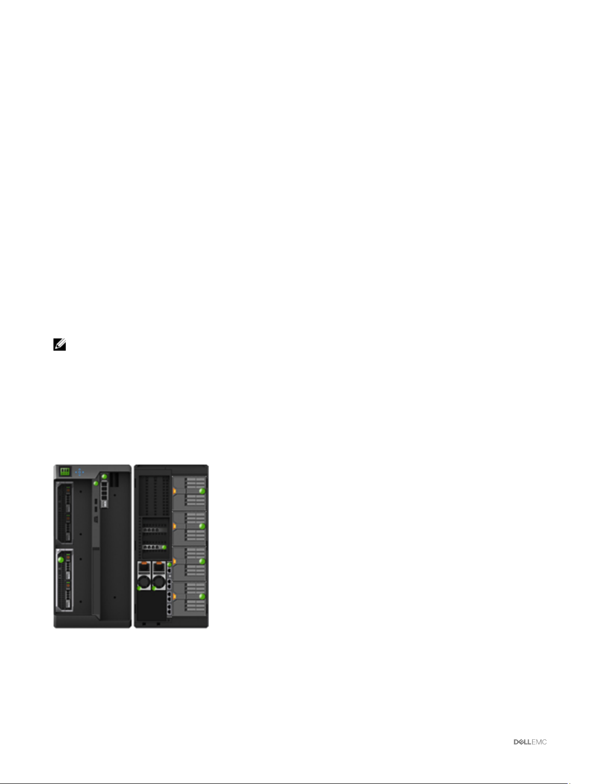
Viewing Chassis Information and Monitoring Chassis and Component Health
You can view information and monitor the health of the following:
• Active and standby CMCs
• All severs and individual servers
• IO Module
• Fans
• Power Supply Units (PSUs)
• Temperature sensors
• Hard disk drives
• LCD assembly
• Storage controllers
• PCIe devices
NOTE: The health of external components impacts the overall health of the storage component with existing storage
health and integrated storage components in VRTX. It indicates that the external components will not impact the health
of any component in the chassis.
5
Viewing Chassis and Component Summaries
When you log in to the CMC web interface, the Chassis Health page displays the health of the chassis and its components. It
displays a graphical view of the chassis and its components. It is dynamically updated, and the component sub-graphic overlays and
text hints are automatically changed to reect the current state.
To view the chassis health, click Chassis Overview. The system displays the overall health status of the chassis, active and standby
CMCs, server modules, IO Module (IOM), fans, blowers, power supply units (PSUs), LCD assembly, storage controller, and PCIe
devices. Detailed information about each component is displayed when you click that component. In addition, the latest events in the
CMC Hardware Log are also displayed. For more information, see the Online Help.
If your chassis is congured as a Group Lead, the Group Health page is displayed after login. It displays the chassis level information
and alerts. All active, critical, and non-critical alerts are displayed.
62
Page 63
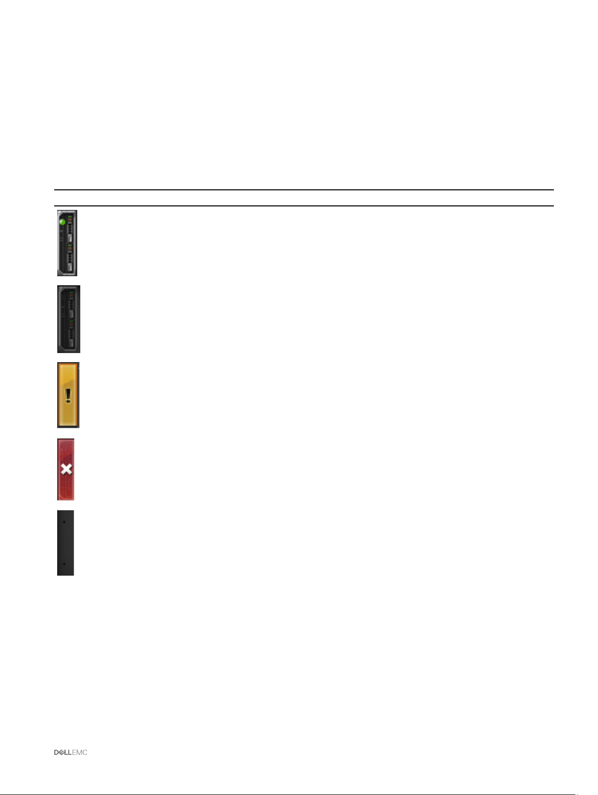
Chassis Graphics
The chassis is represented by the front and back views (the upper and lower images respectively). Servers, DVDs, HDDs, KVMs, and
LCD are shown in the front view and the remaining components are shown in the back view. Component selection is indicated by a
blue cast and is controlled by clicking the image of the required component. When a component is present in the chassis, an icon of
the component type is displayed in the graphics in the position (slot), where the component has been installed. Empty positions are
shown with a charcoal gray background. The component icon visually indicates the state of the component. Other components
display icons that visually represent the physical component. Pausing the cursor over a component displays a tool tip with additional
information about that component.
Table 14. Server Icon States
Icon Description
A server is present, turned on, and is operating normally.
A server is present, but turned o.
A server is present, but reporting a noncritical error.
A server is present, but reporting a critical error.
A server is not present.
Selected Component Information
Information for the selected component is displayed in three independent sections:
• Health and Performance, and Properties — Displays the active, critical, and non-critical events as displayed by the hardware logs
and the performance data that vary with time.
• Properties — Displays the component properties that do not vary with time, or that change only infrequently.
• Quick Links — Provides links to navigate to the most frequently accessed pages, and also the most frequently performed
actions. Only links applicable to the selected component are displayed in this section.
The following table lists the component properties and information displayed on the Chassis Health page in the web interface.
63
Page 64

NOTE: In Multi-Chassis Management (MCM), all the Quick Links associated with the servers are not displayed.
Table 15. Component properties
Component Heath and Performance
Properties
LCD Assembly
• LCD Health
• Chassis Health
Active and Standby
CMCs
• Redundancy Mode
• MAC Address
• IPv4
• IPv6
All Servers and
Individual Servers
• Power State
• Power Consumption
• Health
• Power Allocated
• Temperature
Properties Quick Links
• Chassis Power Button
Front Panel Conguration
• Lock Control Panel LCD
• LCD Language
• LCD Orientation
• Firmware
• Standby Firmware
• Last Update
• CMC Status
• Networking
• Firmware Update
• Hardware
• Name
• Model
• Service Tag
• Host Name
• iDRAC
• CPLD
• BIOS
• OS
• CPU Information
• Total System Memory
• Server Status
• Launch Remote Console
• Launch iDRAC GUI
• Power O Server
• Graceful Shutdown
• Remote File Share
• Deploy iDRAC Network
• Server Component Update
NOTE: Quick links for
Power O Server and
Graceful Shutdown are
displayed only if the
server power state is
On. If the server power
state is O, the quick
link for Power On Server
is displayed.
KVM Slot
DVD Slot
Disk Slot
64
Health
• KVM Mapped
Front Panel Conguration
• Slot 1 : Front Panel USB/Video
Enabled
• Slot 2 : Front Panel USB/Video
Enabled
• Slot 3 : Front Panel USB/Video
Enabled
• Slot 4 : Front Panel USB/Video
Enabled
• Health
• Power State
• DVD Mapped
• Slot 1 : DVD Enabled
Front Panel Conguration
• Slot 2 : DVD Enabled
• Slot 3 : DVD Enabled
• Slot 4 : DVD Enabled
• Health • Model • Physical Disk Status
Page 65

• State • Serial Number
• Power Status
• Firmware Version
• Size
• Type
• Physical Disk Setup
• View Controller for this
Physical Disk
• View Virtual Disks for this
Physical Disk
Power Supply Units
PCIe Devices
Fans
Blower
Power Status Capacity
• Installed
• Assigned
• Speed
• PWM (% of Max)
• Fan Oset
• Speed
• PWM (% of Max)
• Enhanced Cooling Mode
• Model
• Server Slot Mapping
• Vendor ID
• Device ID
• Slot Type
• Allocated Power
• Fabric
• Power Status
• Warning Threshold
• Critical Threshold
• Warning Threshold
• Critical Threshold
• Power Supply Status
• Power Consumption
• System Budget
• PCIe Status
• PCIe Setup
• Fans Status
• Fan Conguration
• Fans Status
• Fan Conguration
SPERC Slot
External Shared
PERC 8 card slot
IOM Slot
• Installed
• Assigned
• Installed
• Assigned
• Power State • Model
• Model
• Server Slot Mapping
• Vendor ID
• Device ID
• Slot Type
• Allocated Power
• Fabric
• Power Status
• Model
• Server Slot Mapping
• Vendor ID
• Device ID
• Slot Type
• Allocated Power
• Fabric
• Power Status
• Controller Status
• Controller Setup
• PCIe Slot Status
• PCIe Setup
IOM Status
65
Page 66

• Role • Service Tag
Launch IOM GUI
Viewing Server Model Name and Service Tag
You can view the model name and service tag of each server instantly using the following steps:
1. In the left pane, under Server Overview tree node, all the servers (SLOT-01 to SLOT-04) appear in the servers list. If a server is
not present in a slot, the corresponding image in the graphic is grayed out. When a full height server occupies slot 1 and slot 3,
slot 3 will show the slot name as Extension of 1.
2. Pause the cursor over the slot name or slot number of a server. A tool tip is displayed with the server’s model name and service
tag (if available).
Viewing Chassis Summary
To view the chassis summary information, in the left pane, click Chassis Overview → Properties → Summary.
The Chassis Summary page is displayed. For more information about this page, see the Online Help.
Viewing Chassis Controller Information and Status
To view the chassis controller information and status, in the CMC Web interface, click Chassis Overview → Chassis Controller.
The Chassis Controller Status page is displayed. For more information, see the Online Help.
Viewing Information and Health Status of All Servers
To view the health status of all the servers, do one of the following:
• Click Chassis Overview. The Chassis Health page displays a graphical overview of all the servers installed in the chassis. Server
health status is indicated by the overlay of the server subgraphic. For more information about the chassis health, see the Online
Help.
• Click Chassis Overview → Server Overview. The Servers Status page provides an overview of the servers in the chassis. For
more information, see the Online Help.
Viewing Health Status and Information for Individual Server
To view health status for individual servers, do any of the following:
1. Go to Chassis Overview → Properties → Health.
The Chassis Health page displays a graphical overview of all the servers installed in the chassis. Server health status is
indicated by the overlay of the server subgraphic. Move the cursor to hover over an individual server subgraphic. A
corresponding text hint or screen tip provides additional information for that server. Click the server subgraphic to view the I/O
Module information on the right. For more information, see the Online Help.
2. Go to Chassis Overview and expand Server Overview in the left pane. All the servers (1–4) appear in the expanded list. Click
the server (slot) you want to view.
The Server Status page (separate from the Servers Status page) provides the health status of the server in the chassis and a
launch point to the iDRAC web interface, which is the rmware used to manage the server. For more information, see the
Online Help.
NOTE: To use the iDRAC web interface, you must have an iDRAC user name and password. For more information
about iDRAC and the using the iDRAC web interface, see the
Guide
.
Integrated Dell Remote Access Controller User’s
66
Page 67

Viewing Information and Health Status of the IOM
To view health status of the IOMs, in the CMC Web interface, do any of the following:
1. Click Chassis Overview.
The Chassis Health page is displayed. The graphics in the left pane displays the rear, front, and side view of the chassis and
contains the health status for the IOM. IOM health status is indicated by the overlay of the IOM sub-graphic. Move the cursor
over the individual IOM sub-graphic. The text hint provides additional information about that IOM. Click the IOM sub-graphic to
view the IOM information in the right pane.
2. Go to Chassis Overview → I/O Module Overview.
The I/O Module Status page provides an overview of IOM associated with the chassis. For more information, see the Online
Help.
NOTE: After updating or power cycling the IOM/IOA, make sure that the operating system of the IOM/IOA is also booted
correctly. Else, the IOM status is displayed as "Oine".
Viewing Information and Health Status of Fans
CMC controls the speed of the chassis fan by increasing or decreasing the fan speed on the basis of system events. You can run the
fan in three modes such as Low, Medium, and High. For more information about conguring a fan, see the Online Help.
To set up the properties of fans by using RACADM commands, type the following command at the CLI interface.
racadm fanoffset [-s <off|low|medium|high>]
For more information about the RACADM commands, see the Chassis Management Controller for PowerEdge VRTX RACADM
Command Line Reference Guide available at dell.com/cmcmanuals.
NOTE: The CMC monitors the temperature sensors in the chassis and automatically adjust the fan speed as needed.
However, you can override to maintain a minimum fan speed by the racadm fanoset command. When overriden using
this command, the CMC will always run the fan to the selected speed even though the chassis does not require the fans
to run at that speed.
CMC generates an alert and increases the fan speeds when the following events occur:
• CMC ambient temperature threshold is exceeded.
• A fan stops functioning.
• A fan is removed from the chassis.
NOTE: During updates of CMC or iDRAC rmware on a server, some or all of the fan units in the chassis rotates at 100%.
This is normal.
To view the health status of fans, in the CMC Web interface, do any of the following:
1. Go to Chassis Overview.
The Chassis Health page is displayed. The lower section of chassis graphics provides the left view of the chassis and contains
the health status of the fans. Fan health status is indicated by the overlay of the fan sub-graphic. Move the cursor over the fan
sub-graphic. The text hint provides additional information about a fan. Click the fan subgraphic to view the fan information in
the right pane.
2. Go to Chassis Overview → Fans.
The Fans Status page provides the status, speed measurements in revolutions per minute (RPMs), and threshold values of the
fans in the chassis. There can be one or more fans.
NOTE: In the event of a communication failure between CMC and the fan unit, CMC cannot obtain or display the
health status for the fan unit.
NOTE: The following message is displayed when both the fans are not present in the slots or if a fan is rotating at a
low speed:
Fan <number> is less than the lower critical threshold.
67
Page 68

For more information, see the Online Help.
Conguring Fans
Fan Oset — A feature to provide increased cooling to the storage and PCIe regions of the chassis. This feature allows you to
increase the airow delivery to the HDDs, Shared PERC controllers, and PCIe card slots. An example usage of the Fan Oset is
when you use high-power or custom PCIe cards that require more cooling than normal. The Fan Oset feature has options of O,
Low, Medium, and High. These settings correspond to a fan speed oset (increase) of 20%, 50%, and 100% of the maximum speed
respectively. There are also minimum speeds setup for each option, which are 35% for Low, 65% for Medium, and 100% for High.
Using the Medium Fan Oset setting for example, increases the speed of fans 1–6 by 50% of its maximum speed. The increase is
above the speed already set by the system for cooling on the basis of installed hardware conguration.
With any of the Fan Oset options enabled, the power consumption will be increased. The system will be louder with the Low oset,
noticeably louder with the Medium oset, and signicantly louder with the High oset. When the Fan Oset option is not enabled,
the fan speeds will be reduced to the default speeds required for system cooling for the installed hardware conguration.
To set the oset feature, go to Chassis Overview → Fans → Setup. On the Advanced Fan Congurations page, in the Fan
Conguration table, from the Value drop-down menu corresponding to Fan Oset, select an option appropriately.
For more information about the Fan Oset feature, see the Online Help.
For setting up these features by using RACADM commands, user the following command:
racadm fanoffset [-s <off|low|medium|high>]
For more information about the fan oset-related RACADM commands, see the Chassis Management Controller for PowerEdge
VRTX RACADM Command Line Reference Guide available at dell.com/support/Manuals.
Enhanced Cooling Mode (ECM) — Is a feature in the CMC that allows increased cooling capacity for the servers installed within
the PowerEdge VRTX chassis. Example uses for ECM are operation in a high ambient environment or using servers with high power
(≥120W) CPUs installed. The increased cooling capacity is achieved by allowing the four chassis blower modules to run at a higher
speed. As a result, the system power consumption and noise level may be increased when ECM is enabled.
When enabled, ECM will only increase the cooling capacity to the server slots within the chassis. It is also important to note that
ECM is not designed to provide increased cooling to the servers at all times. Even with ECM enabled, the higher blower speeds will
only be seen when the increased cooling is needed. Examples of this situation include high levels of server utilization or stress, and
high ambient temperatures.
By default, ECM is o. When ECM is enabled, the blowers have the capability to deliver approximately 20% more airow per blade.
To set the ECM mode, go to Chassis Overview → Fans → Setup. On the Advanced Fan Congurations page, in the Blower
Congurationtable, from the Value drop-down menu corresponding to Enhanced Cooling Mode, select an option appropriately.
For more information about the ECM feature, see the Online Help.
Viewing Front Panel Properties
To view the front panel properties:
1. In the left pane, click Chassis Overview → Front Panel.
2. On the Properties page, you can view the following:
• Power Button Properties
• LCD Properties
• KVM Properties
• DVD Drive Properties
Viewing KVM Information and Health Status
To view the health status of the KVMs associated with the chassis, do any of the following:
1. Click Chassis Overview.
The Chassis Health page is displayed. The left pane displays the front view of the chassis and contains the health status of a
KVM. KVM health status is indicated by the overlay of the KVM sub-graphic. Move the pointer over an KVM sub-graphic and a
68
Page 69

corresponding text hint or screen tip is displayed. The text hint provides additional information about the KVM. Click the KVM
sub-graphic to view the KVM information in the right pane.
2. Alternatively, click Chassis Overview → Front Panel.
On the Status page, under the KVM Properties section, you can view the status and properties of a KVM associated with the
chassis. For more information, see the Online Help.
Viewing LCD Information and Health
To view the health status of an LCD:
1. In the left pane, click Chassis Overview.
The Chassis Health page is displayed. The left pane displays the front view of the chassis. LCD health status is indicated by the
overlay of the LCD sub-graphic.
2. Move the cursor over the LCD subgraphic. The corresponding text hint or screen tip provides additional information on the LCD.
3. Click the LCD sub-graphic to view the LCD information in the right pane. For more information, see the Online Help.
Alternatively, go to Chassis Overview → Front Panel → Properties → Status. On the Status page, under the LCD Properties,
you can view the status of the LCD available on the chassis. For more information, see Online Help.
Viewing Information and Health Status of Temperature Sensors
To view the health status of the temperature sensors:
In the left pane, click Chassis Overview → Temperature Sensors.
The Temperature Sensors Status page displays the status and readings of the temperature probes on the entire chassis
(chassis and servers). For more information, see Online Help.
NOTE: The temperature probes value cannot be edited. Any change beyond the threshold generates an alert that
causes the fan speed to vary. For example, if the CMC ambient temperature probe exceeds the threshold, the speed
of the fans on the chassis increases.
Viewing Storage Capacity and Status of the Storage Components
To view the capacity and fault-tolerant status of the storage components, do one of the following:
1. Go to Chassis Overview.
The Chassis Health page is displayed. The Storage capacity details, the Fault Tolerant Mode (Active/Passive), and Fault
Tolerant Status (Enabled) information is displayed on the right pane. This fault-tolerance information is displayed only if the fault
tolerant feature is enabled for the storage components.
The lower section of chassis graphics provides the left view of the chassis. Move the cursor over the storage component subgraphic. The text hint provides additional information about the storage component. Click the storage component subgraphic to
view the related information in the right pane.
2. Alternatively, in the left pane, click Chassis Overview → Storage → Properties → Status.
The Storage Overview page is displayed with the following information:
• View the graphic summary of the physical disk drives installed in the chassis and their status.
• View the summary of all the storage components with links to their respective pages.
• View the used capacity and total capacity of the storage.
• View controller information.
NOTE: In case of a fault-tolerant controller, the name format is: Shared
For example, the active controller is Shared PERC8 (Integrated 1) and the peer controller is Shared PERC8
(Integrated 2).
• View recently-logged storage events.
<PERC number
> (Integrated <number>).
69
Page 70

NOTE: For more information, see the
Online Help
.
70
Page 71

6
Conguring CMC
Chassis Management Controller enables you to congure properties, set up users, and alerts to perform remote management tasks.
Before you begin conguring the CMC, you must rst congure the CMC network settings to allow CMC to be managed remotely.
This initial conguration assigns the TCP/IP networking parameters that enable access to the CMC. For more information, see
Setting Up Initial Access to CMC.
You can congure CMC using Web interface or RACADM.
NOTE: When you congure CMC for the rst time, you must be logged in as root user to execute RACADM commands
on a remote system. Another user can be created with privileges to congure CMC.
After setting up the CMC and performing the basic congurations, you can do the following:
• Modify the network settings, if required.
• Congure interfaces to access CMC.
• Congure LCD display.
• Set up chassis groups, if required.
• Congure servers, I/O module, or front panel.
• Congure VLAN settings.
• Obtain the required certicates.
• Add and congure CMC users with privileges.
• Congure and enable e-mail alerts and SNMP traps.
• Set the power cap policy, if required.
NOTE: The following characters cannot be used in the property strings of both the CMC interfaces (GUI and CLI):
• &#
• < and > together
• ; (semicolon)
Viewing and Modifying CMC Network LAN Settings
The LAN settings, such as community string and SMTP server IP address, aect both the CMC and the external settings of the
chassis.
If you have two CMCs (active and standby) on the chassis that are connected to the network, the standby CMC automatically
assumes the network settings of the active CMC in the event of failover.
When IPv6 is enabled at boot time, three router solicitations are sent after every four seconds. If external network switches are
running the Spanning Tree Protocol (STP), the external switch ports may be blocked for more than 12 seconds in which the IPv6
router solicitations are sent. In such cases, there may be a period when IPv6 connectivity is limited, until router advertisements are
gratuitously sent by the IPv6 routers.
NOTE: Changing the CMC network settings may disconnect your current network connection.
NOTE: You must have Chassis Conguration Administrator privilege to set up CMC network settings.
71
Page 72

Viewing and Modifying CMC Network LAN Settings Using CMC Web Interface
To view and modify the CMC LAN network settings using CMC Web interface:
1. In the left pane, click Chassis Overview, and then click Network. The Network Conguration page displays the current
network settings.
2. Modify the general, IPv4, or IPv6 settings as required. For more information, see the Online Help.
3. Click Apply Changes for each section to apply the settings.
Viewing and Modifying CMC Network LAN Settings Using RACADM
To view IPv4 settings, use the objects from the cfgCurrentLanNetworking group with the following getniccfg and getconfig
subcommands.
To view IPv6 settings, use the objects from the cfgIpv6LanNetworking group with the getconfig subcommand.
To view IPv4 and IPv6 addressing information for the chassis, use the getsysinfo subcommand.
For more information about the subcommands and objects, see the Chassis Management Controller for PowerEdge VRTX RACADM
Command Line Reference Guide.
Enabling the CMC Network Interface
To enable or disable the CMC network interface for both IPv4 and IPv6, type:
racadm config -g cfgLanNetworking -o cfgNicEnable 1
racadm config -g cfgLanNetworking -o cfgNicEnable 0
NOTE: The CMC NIC is enabled by default.
To enable or disable the CMC IPv4 addressing, type:
racadm config -g cfgLanNetworking -o cfgNicIPv4Enable
1
racadm config -g cfgLanNetworking -o cfgNicIPv4Enable
0
NOTE: The CMC IPv4 addressing is enabled by default.
To enable or disable the CMC IPv6 addressing, type:
racadm config -g cfgIpv6LanNetworking -o cfgIPv6Enable
1
racadm config -g cfgIpv6LanNetworking -o cfgIPv6Enable
0
NOTE: Note the following:
• There is a 30 seconds delay between changing a network setting and actually applying it.
• The CMC IPv6 addressing is disabled by default.
By default, for IPv4, the CMC requests and automatically obtains a CMC IP address from the Dynamic Host Conguration Protocol
(DHCP) server. You can disable the DHCP feature and specify static CMC IP address, gateway, and subnet mask.
For an IPv4 network, to disable DHCP and specify static CMC IP address, gateway, and subnet mask, type:
racadm config -g cfgLanNetworking -o cfgNicUseDHCP 0
racadm config -g cfgLanNetworking -o cfgNicIpAddress <static IP address>
racadm config -g cfgLanNetworking -o cfgNicGateway <static gateway>
racadm config -g cfgLanNetworking -o cfgNicNetmask <static subnet mask>
By default, for IPv6, the CMC requests and automatically obtains a CMC IP address from the IPv6 autoconguration mechanism.
For an IPv6 network, to disable the Autoconguration feature and specify a static CMC IPv6 address, gateway, and prex length,
type:
racadm config -g cfgIPv6LanNetworking -o
cfgIPv6AutoConfig 0
racadm config -g cfgIPv6LanNetworking -o
72
Page 73

cfgIPv6Address <IPv6 address>
racadm config -g cfgIPv6LanNetworking -o
cfgIPv6PrefixLength 64
racadm config -g cfgIPv6LanNetworking -o
cfgIPv6Gateway <IPv6 address>
Enabling or Disabling DHCP for the CMC Network Interface Address
When enabled, the CMC’s DHCP for NIC address feature requests and obtains an IP address from the Dynamic Host Conguration
Protocol (DHCP) server automatically. This feature is enabled by default.
You can disable the DHCP for NIC address feature and specify a static IP address, subnet mask, and gateway. For more information,
see Setting Up Initial Access to CMC.
Enabling or Disabling DHCP for DNS IP Addresses
By default, the CMC’s DHCP for DNS address feature is disabled. When enabled, this feature obtains the primary and secondary
DNS server addresses from the DHCP server. While using this feature, you do not have to congure static DNS server IP addresses.
To disable the DHCP for DNS address feature and specify the static preferred and alternate DNS server addresses, type:
racadm config -g cfgLanNetworking -o
cfgDNSServersFromDHCP 0
To disable the DHCP for DNS address feature for IPv6 and specify the static preferred and alternate DNS server addresses, type:
racadm config -g cfgIPv6LanNetworking -o
cfgIPv6DNSServersFromDHCP6 0
Setting Static DNS IP addresses
NOTE: The static DNS IP addresses settings are not valid unless the DCHP for DNS address feature is disabled.
For IPv4, to set the preferred primary and secondary DNS IP server addresses, type:
racadm config -g cfgLanNetworking -o cfgDNSServer1 <IP-address>
racadm config -g cfgLanNetworking -o cfgDNSServer2 <IPv4-address>
For IPv6, to set the preferred and secondary DNS IP Server addresses, type:
racadm config -g cfgIPv6LanNetworking -o
cfgIPv6DNSServer1 <IPv6-address>
racadm config -g cfgIPv6LanNetworking -o
cfgIPv6DNSServer2 <IPv6-address>
Conguring IPv4 and IPv6 DNS Settings
• CMC Registration — To register the CMC on the DNS server, type:
racadm config -g cfgLanNetworking -o
cfgDNSRegisterRac 1
NOTE: Some DNS servers only register names of 31 characters or fewer. Make sure the designated name is within the
DNS required limit.
NOTE: The following settings are valid only if you have registered the CMC on the DNS server by setting
cfgDNSRegisterRac to 1.
• CMC Name — By default, the CMC name on the DNS server is cmc-<service tag>. To change the CMC name on the DNS
server, type:
racadm config -g cfgLanNetworking -o cfgDNSRacName <name>
where <name> is a string of up to 63 alphanumeric characters and hyphens. For example: cmc-1, d-345.
NOTE: If a DNS Domain name is not specied then the maximum number of characters is 63. If a domain name is
specied then the number of characters in CMC name plus the number of characters in the DNS Domain Name must
be less than or equal to 63 characters.
73
Page 74

• DNS Domain Name — The default DNS domain name is a single blank character. To set a DNS domain name, type:
racadm config -g cfgLanNetworking -o
cfgDNSDomainName <name>
where <name> is a string of up to 254 alphanumeric characters and hyphens. For example: p45, a-tz-1, r-id-001.
Conguring Auto Negotiation, Duplex Mode, and Network Speed for IPv4 and IPv6
When enabled, the auto negotiation feature determines whether the CMC automatically sets the duplex mode and network speed by
communicating with the nearest router or switch. By default, auto negotiation feature is enabled.
You can disable auto negotiation and specify the duplex mode and network speed by typing:
racadm config -g cfgNetTuning -o cfgNetTuningNicAutoneg 0
racadm config -g cfgNetTuning -o cfgNetTuningNicFullDuplex <duplex mode>
where:
<duplex mode> is 0 (half duplex) or 1 (full duplex, default)
racadm config -g cfgNetTuning -o cfgNetTuningNicSpeed <speed>
where:
<speed> is 10 or 100 (default).
Setting the Maximum Transmission Unit for IPv4 and IPv6
The Maximum Transmission Unit (MTU) property allows you to set a limit for the largest packet that can be passed through the
interface. To set the MTU, type:
racadm config -g cfgNetTuning -o cfgNetTuningMtu <mtu>
where <mtu> is a value between 576–1500 (inclusive; default is 1500).
NOTE: IPv6 requires a minimum MTU of 1280. If IPv6 is enabled, and cfgNetTuningMtu is set to a lower value, the
CMC uses an MTU of 1280.
Conguring CMC Network and Login Security Settings
The IP address blocking and User blocking features in CMC allow you to prevent security issues due to password guessing attempts.
This feature enables you to block a range of IP addresses and users who can access CMC. By deafult, the IP address blocking
feature is enabled in CMC. You can set the IP range attributes using CMC web interface or RACADM. To use the IP address blocking
and user blocking features, enable the options using CMC web interface or RACADM. Congure the login lockout policy settings to
enable you to set the number of unsuccessful login attempts for a specic user or for an IP address. After exceeding this limit, the
blocked user can log in only after the penalty time expires.
NOTE: Blocking by IP address is applicable only for IPV4 addresses.
Conguring IP Range Attributes Using CMC Web Interface
NOTE: To perform the following task, you must have Chassis Conguration Administrator privilege.
To congure the IP range attributes using CMC web interface:
1. In the left pane, go to Chassis Overview and click Network → Network. The Network Conguration page is displayed.
2. In the IPv4 Settings section, click Advanced Settings.
The Log in Security page is displayed.
Alternatively, to access the Log in Security page, in the left pane, go to Chassis Overview, click Security → Log in.
3. To enable the IP range checking feature, in the IP Range section, select the IP Range Enabled option.
The IP Range Address and IP Range Mask elds are activated.
4. In the IP Range Address and IP Range Mask elds, type the range of IP addresses and IP range masks that you want to block
from accessing CMC.
74
Page 75

For more information, see the Online Help.
5. Click Apply to save your settings.
Conguring IP Range Attributes Using RACADM
You can congure the following IP Range attributes for CMC using RACADM:
• IP range checking feature
• Range of IP addresses that you want to block from accessing CMC
• IP Range Mask that you want to block from accessing CMC
IP ltering compares the IP address of an incoming login to the IP address range that is specied. A login from the incoming IP
address is allowed only if both the following are identical:
• cfgRacTuneIpRangeMask bit-wise and with incoming IP address
• cfgRacTuneIpRangeMask bit-wise and with cfgRacTuneIpRangeAddr
• To enable the IP range checking feature, use the following property under cfgRacTuning group:
cfgRacTuneIpRangeEnable <0/1>
• To specify the range of IP addresses that you want to block from accessing CMC, use the following property under
cfgRacTuning group:
cfgRacTuneIpRangeAddr
•
To specify the IP Range Mask that you want to block from accessing CMC, use the following property under cfgRacTuning
group:
cfgRacTuneIpRangeMask
Conguring Virtual LAN Tag Properties for CMC
Virtual LANfunctionality enables multiple VLANs to coexist on the same physical network cable and to segregate the network trac
for security or load management purposes. When you enable the VLAN functionality, each network packet is assigned a VLAN tag.
Conguring Virtual LAN Tag Properties for CMC Using RACADM
1. Enable the Virtual LAN (VLAN) capabilities of the external chassis management network:
racadm config -g cfgLanNetworking -o
cfgNicVLanEnable 1
2. Specify the VLAN ID for the external chassis management network:
racadm config -g cfgLanNetworking -o cfgNicVlanID <VLAN id>
The valid values for <VLAN id> are 1– 4000 and 4021– 4094. Default value is 1.
For example:
racadm config -g cfgLanNetworking -o cfgNicVlanID
1
3. Then, specify the VLAN priority for the external chassis management network:
racadm config -g cfgLanNetworking -o
cfgNicVLanPriority <VLAN priority>
The valid values for <VLAN priority> are 0–7. Default value is 0.
For example:
racadm config -g cfgLanNetworking -o
cfgNicVLanPriority 7
You can also specify both the VLAN ID and the VLAN priority with a single command:
racadm setniccfg -v <VLAN id> <VLAN priority>
For example:
racadm setniccfg -v 1 7
75
Page 76

4. To remove the CMC VLAN, disable the VLAN capabilities of the external chassis management network:
racadm config -g cfgLanNetworking -o
cfgNicVLanEnable 0
You can also remove the CMC VLAN using the following command:
racadm setniccfg -v
Conguring Virtual LAN Tag Properties for CMC Using Web Interface
To congure Virtual LAN(VLAN) for CMC using the CMC Web interface:
1. Go to any of the following pages:
• In the left pane, click Chassis Overview and click Network → VLAN.
• In the left pane, click Chassis Overview → Server Overview and click Network → VLAN.
The VLAN Tag Settings page is displayed. VLAN tags are chassis properties. They remain with the chassis even when a
component is removed.
2. In the CMC section, enable VLAN for CMC, set the priority and assign the ID. For more information about the elds, see the
Online Help.
3. Click Apply. The VLAN tag settings are saved.
You can also access this page from the Chassis Overview → Servers → Setup → VLAN.
Federal Information Processing Standards
The agencies and contractors of the Federal government of the United States use Federal Information Processing Standards (FIPS),
a computer security standard, which is related to all applications that have communicative interfaces. The 140–2 comprises of four
levels — Level 1, Level 2, Level 3, and Level 4. The FIPS 140–2 series stipulate that all communicative interfaces must have the
following security properties:
• authentication
• condentiality
• message integrity
• non-repudiation
• availability
• access control
If any of the properties depend on cryptographic algorithms, then FIPS must approve these algorithms.
By default, the FIPS mode is disabled. When FIPS is enabled, the minimum key size for OpenSSL FIPS is SSH-2 RSA 2048 bits.
NOTE: PSU rmware update is not supported when the FIPS mode is enabled in the chassis.
For more information, see CMC Online Help.
The following features/applications support FIPS.
• Web GUI
• RACADM
• WSMan
• SSH v2
• SMTP
• Kerberos
• NTP Client
• NFS
76
Page 77

NOTE: SNMP is not FIPS-compliant. In FIPS mode, all SNMP features except Message Digest algorithm version 5
(MD5) authentication work.
Enabling FIPS Mode Using CMC Web Interface
To enable FIPS:
1. In the left pane, click Chassis Overview.
The Chassis Health page is displayed.
2. On the menu bar, click Network.
The Network Conguration page is displayed.
3. Under the Federal Information Processing Standards (FIPS) section, from the FIPS Mode drop-down menu, select Enabled.
A message is displayed that enabling FIPS resets CMC to the default settings.
4. Click OK to proceed.
Enabling FIPS Mode Using RACADM
To enable FIPS mode, run the following command:
racadm config –g cfgRacTuning –o cfgRacTuneFipsModeEnable 1
.
Disabling FIPS Mode
To disable FIPS mode, reset CMC to the default factory settings.
Conguring Services
You can congure and enable the following services on CMC:
• CMC serial console — Enable access to CMC using the serial console.
• Web Server — Enable access to CMC web interface. Disabling the web server also disables Remote RACADM.
• SSH — Enable access to CMC through rmware RACADM.
• Telnet — Enable access to CMC through rmware RACADM
• RACADM — Enable access to CMC using RACADM.
• SNMP — Enable CMC to send SNMP traps for events.
• Remote Syslog — Enable CMC to log events to a remote server. To use this feature, you must have an Enterprise license.
CMC includes a web server that is congured to use the industry-standard SSL security protocol to accept and transfer encrypted
data from and to clients over the Internet. The web server includes a Dell self-signed SSL Digital Certicate (Server ID), and is
responsible for accepting and responding to secure HTTP requests from clients. This service is required by the web interface and
remote RACADM CLI tool for communicating with CMC.
If the web server resets, wait at least one minute for the services to become available again. A web server reset usually happens as a
result of any of the following events:
• Network conguration or network security properties are changed through the CMC web user interface or RACADM.
• Web server port conguration is changed through the web user interface or RACADM.
• CMC is reset.
• A new SSL server certicate is uploaded.
NOTE: To modify service settings, you must have the Chassis Conguration Administrator privilege.
Remote syslog is an additional log target for CMC. After you congure the remote syslog, each new log entry generated by CMC is
forwarded to the respective destinations.
77
Page 78

NOTE: Because the network transport for the forwarded log entries is UDP, there is no guaranteed delivery of log
entries, nor is there any feedback to CMC about whether the log entries were received successfully.
Conguring Services Using CMC Web Interface
To congure CMC services using CMC web interface:
1. In the left pane, click Chassis Overview, and then click Network → Services. The Services Management page is displayed.
2. Congure the following services as required:
• CMC Serial
• Web Server
• SSH
• Telnet
• Remote RACADM
• SNMP
• Remote Syslog
For information about the elds, see the Online Help.
3. Click Apply, and then update all default time-out and maximum time-out limits.
Conguring Services Using RACADM
To enable and congure the various services, use the following RACADM objects:
• cfgRacTuning
• cfgRacTuneRemoteRacadmEnable
For more information about these objects, see the Chassis Management Controller for PowerEdge VRTX RACADM Command Line
Reference Guide available at dell.com/support/manuals.
If the rmware on the server does not support a feature, conguring a property related to that feature displays an error. For example,
using RACADM to enable remote syslog on an unsupported iDRAC displays an error message.
Similarly, when displaying the iDRAC properties using the RACADM getconfig command, the property values are displayed as N/A
for an unsupported feature on the server.
For example:
$ racadm getconfig -g cfgSessionManagement -m server-1
# cfgSsnMgtWebServerMaxSessions=N/A
# cfgSsnMgtWebServerActiveSessions=N/A
# cfgSsnMgtWebServerTimeout=N/A
# cfgSsnMgtSSHMaxSessions=N/A
# cfgSsnMgtSSHActiveSessions=N/A
# cfgSsnMgtSSHTimeout=N/A
# cfgSsnMgtTelnetMaxSessions=N/A
# cfgSsnMgtTelnetActiveSessions=N/A
# cfgSsnMgtTelnetTimeout=N/A
Conguring CMC Extended Storage Card
You can enable or repair the optional Removable Flash Media for use as an extended non-volatile storage. Some CMC features
depend on extended nonvolatile storage for their operation.
To enable or repair the Removable Flash Media using the CMC web interface:
1. In the left pane, go to Chassis Overview, and then click Chassis Controller → Flash Media.
2. On the Removable Flash Media page, from the drop-down menu, select one of the following as appropriate:
• Repair active controller media
78
Page 79

• Stop using ash media for storing chassis data
For more information about these options, see the Online Help.
3. Click Apply to apply the selected option.
If two CMCs are present in the chassis, both CMCs (active and standby) must contain ash media; else, the Extended Storage
functionality will be degraded unless both the active and standby CMCs contain ash media.
Setting Up Chassis Group
CMC enables you to monitor multiple chassis from a single lead chassis. When a chassis group is enabled, CMC in the lead chassis
generates a graphical display of the status of the lead chassis and all member chassis within the chassis group. To use this feature,
you must have an Enterprise License.
The Chassis group features are:
• Displays images portraying the front and back of each chassis, a set for the leader and a set for each member.
• Health concerns for the leader and members of a group are recognized by red or yellow overlays and an X or an ! on the
component with the symptoms. Details are visible below the chassis image when you click the chassis image or Details.
• Quick launch links are available for opening member chassis’s or server’s web pages.
• A server and Input/Output inventory is available for a group.
• A selectable option is available to synchronize a new member’s properties to the leader’s properties when the new member is
added to the group.
A chassis group may contain a maximum of eight members. Also, a leader or member can only participate in one group. You cannot
join a chassis, either as a leader or member, that is part of a group to another group. You can delete the chassis from a group and add
it later to a dierent group.
To set up the Chassis Group using the CMC web interface:
1. Log in with chassis administrator privileges to the leader chassis.
2. Click Setup → Group Administration.
3. On the Chassis Group page, under Role, select Leader. A eld to add the group name is displayed.
4. Type the group name in the Group Name eld, and then click Apply.
NOTE: The same rules that apply for a domain name apply to the group name.
When the chassis group is created, the GUI automatically switches to the Chassis Group page. The left pane indicates the
group by the group name and the lead chassis, and the unpopulated member chassis appear in the left pane.
Adding Members To Chassis Group
After the Chassis Group is set up, to add members to the group:
1. Log in with chassis administrator privileges to the leader chassis.
2. Select the lead chassis in the tree.
3. Click Setup → Group Administration.
4. Under Group Management, enter the member’s IP address or DNS name in the Hostname/IP Address eld.
5. In the User Name eld, enter a user name with chassis administrator privileges for the member chassis.
6. Type the corresponding password in the Password eld.
7. Optionally, select Sync New Member with Leader Properties to push leader properties to the member.
8. Click Apply.
9. To add a maximum of eight members, complete the tasks in step 4 through step 8. The chassis names of the new members
appear in the Members dialog box.
NOTE: The credentials entered for a member are passed securely to the member chassis to establish a trust
relationship between the member and lead chassis. The credentials are not persisted on either chassis, and are never
exchanged again after the initial trust relationship is established.
79
Page 80

Removing a Member from the Leader
You can remove a member from the group from the lead chassis. To remove a member:
1. Log in with chassis administrator privileges to the leader chassis.
2. In the left pane, select the lead chassis.
3. Click Setup → Group Administration.
4. From the Remove Members list, select the member’s name to be deleted, and then click Apply.
The lead chassis then communicates to the member or members, if more than one is selected, that it has been removed from
the group. The member name is removed. The member chassis may not receive the message, if a network issue prevents
contact between the leader and the member. In this case, disable the member from the member chassis to complete the
removal.
Disbanding a Chassis Group
To disband a chassis group from the lead chassis:
1. Log in with administrator privileges to the leader chassis.
2. Select the lead chassis in the left pane.
3. Click Setup → Group Administration.
4. In the Chassis Group page, under Role, select None, and then click Apply.
The lead chassis then communicates to all the members that they have been removed from the group. The lead chassis can be
assigned as a leader or member of a new group.
If a network issue prevents contact between the leader and the member, the member chassis may not receive the message. In
this case, disable the member from the member chassis to complete the removal process.
Disabling an Individual Member at the Member Chassis
Sometimes a member cannot be removed from a group by the lead chassis. This can happen if network connectivity to the member
is lost. To remove a member from a group at the member chassis:
1. Log in with chassis administrator privileges to the member chassis.
2. In the left pane, click Chassis Overview → Setup → Group Administration.
3. Select None, and then click Apply.
Accessing the Web page of a Member Chassis or Server
You can access the web page of the member chassis, remote console of the server, or the web page of the iDRAC server from the
lead chassis group page. If the member device has the same login credentials as the lead chassis, you can use the same credentials
to access the member device.
NOTE: Single Sign-On and Smart Card Login are not supported in Multiple Chassis Management. To access members by
Single Sign On from lead chassis requires a common username or password between Lead and members. Use of common
username or password works only with Active Directory, local, and LDAP users.
To navigate to member devices:
1. Log in to the lead chassis.
2. Select Group: name in the tree.
3. If a member CMC is the required destination, select Launch CMC for the required chassis.
If a server in a chassis is the required destination:
a. Select the image of the destination chassis.
b. In the chassis image that is displayed in the Health section, select the server.
c. In the box labeled Quick Links, select the destination device. A new window is displayed with the destination page or login
screen.
80
Page 81

NOTE: In MCM, all the Quick Links associated with the servers are not displayed.
Propagating Leader Chassis Properties to Member Chassis
You can apply the properties from the leader to the member chassis of a group. To synchronize a member with the leader properties:
1. Login with administrator privileges to the leader chassis.
2. Select the Lead chassis in the tree.
Click Setup → Group Administration.
3.
4. In the Chassis Properties Propagation section, select one of the propagation types:
• On-Change Propagation — Select this option for automatic propagation of the selected chassis property settings. The
property changes are propagated to all current group members, whenever lead properties are changed.
• Manual Propagation — Select this option for manual propagation of the chassis group leader properties with its members.
The lead chassis property settings are propagated to group members only when a lead chassis administrator clicks
Propagate.
5. In the Propagation Properties section, select the categories of lead conguration properties to be propagated to member
chassis.
Select only those setting categories that you want identically congured, across all members of the chassis group. For example,
select Logging and Alerting Properties category, to enable all chassis in the group to share the logging and alerting
conguration settings of the lead chassis.
6. Click Save.
If On-Change Propagation is selected, the member chassis take on the properties of the leader. If Manual Propagation is
selected, click Propagate whenever you want to propagate the chosen settings to member chassis. For more information on
propagation of leader chassis properties to member chassis, see the Online Help.
Server Inventory for MCM group
A group is a lead chassis that has 0 to 8 chassis group members. The Chassis Group Health page displays all the member chassis
and allows you to save the server inventory report to a le, using standard browser download capability. The report contains data for:
• All servers currently in all the group chassis (including the leader).
• Empty slots and extension slots (including full height and double width server modules).
Saving Server Inventory Report
To save the server inventory report using the CMC web interface:
1. In the left pane, select the Group.
2. On the Chassis Group Health page, click Save Inventory Report. The File Download dialog box is displayed asking you to open
or save the le.
3. Click Save and specify the path and le name for the server module inventory report.
NOTE: The chassis group leader and chassis group member chassis, and the server module in the associated
chassis, must be turned on to get the most accurate server module inventory report.
Exported Data
The server inventory report contains data that was most recently returned by each Chassis Group member during the Chassis Group
leader’s normal polling (after every 30 seconds).
To get the most accurate server inventory report:
• The Chassis Group leader chassis and all Chassis Group member chassis must be in Chassis Power State On.
• All servers in the associated chassis must be turned on.
The inventory data for the associated chassis and servers may be missing in inventory report, if a subset of the Chassis Group
member chassis are:
81
Page 82

• In Chassis Power State O state
• Turned o
NOTE: If a server is inserted while the chassis is turned o, the model number is not displayed anywhere in the web
interface until the chassis is turned on again.
The following table lists the specic data elds and specic requirements for elds to be reported for each server:
Table 16. Server Module Inventory Field Descriptions
Data Field Example
Chassis Name Data Center Chassis Leader
Chassis IP Address 192.168.0.1
Slot Location 1
Slot Name SLOT-01
Host Name Corporate Webserver
NOTE: Requires a Server Administrator agent running on the Server; otherwise shown as
blank.
Operating System Windows Server 2008
NOTE: Requires a Server Administrator agent running on the Server; otherwise shown as
blank.
Model PowerEdgeM610
Service Tag 1PB8VF1
Total System Memory 4.0 GB
NOTE: Requires VRTX CMC 1.0 (or later) on member; otherwise shown as blank.
# of CPUs 2
NOTE: Requires VRTX CMC 1.0 (or later) on member; otherwise shown as blank.
CPU Info Intel (R) Xeon (R) CPU E5502 @1.87GHzn
NOTE: Requires VRTX CMC 1.0 (or later) on member; otherwise shown as blank.
Data Format
The inventory report is generated in a .CSV le format such that it can be imported to various tools, such as Microsoft Excel. The
inventory report
report is imported into MS Excel, and if a message is displayed asking you for additional information, select comma-delimited to
import the le into MS Excel.
.CSV le can be imported into the template by selecting the Data → From Text in MS Excel. After the inventory
Chassis Group Inventory and Firmware Version
The Chassis Group Firmware Version page displays the group inventory and rmware versions of the servers and the server
components in the chassis. This page also enables you to organize the inventory information and lter the rmware versions view.
The displayed view is based on the servers or any of the following chassis server components:
• BIOS
• iDRAC
• CPLD
• USC
• Diagnostics
• OS Drivers
82
Page 83

• RAID
• NIC
NOTE: The inventory information displayed for the chassis group, member chassis, servers, and server components is
updated every time a chassis is added or removed from the group.
Viewing Chassis Group Inventory
To view the chassis group using CMC web interface, in the left pane, select Group. Click Properties → Firmware Version. The
Chassis Group Firmware Version page displays all the chassis in the group.
Viewing Selected Chassis Inventory Using Web Interface
To view the selected chassis inventory using CMC Web interface:
1. In the system tree, select Group. click Properties → Firmware Version.
The Chassis Group Firmware Version page displays all the chassis in the group.
2. In the Select a Chassis section, select the member chassis for which you want to view the inventory.
The Firmware View Filter section displays the server inventory for the selected chassis and the rmware versions of all the
server components.
Viewing Selected Server Component Firmware Versions Using Web Interface
To view the rmware versions of selected server components using CMC web interface:
1. In the left pane, select Group. Click Properties → Firmware Version.
The Chassis Group Firmware Version page displays all the chassis in the group.
2. In the Select a Chassis section, select the member chassis for which you want to view the inventory.
3. In the Firmware View Filter section, select Components.
4. In the Components list, select the required component- BIOS, iDRAC, CPLD, USC, Diagnostics, OS Drive, RAID devices (up to
2), and NIC devices (up to 6), for which you want to view the rmware version.
The rmware versions of the selected component for all the servers in the selected member chassis are displayed.
Chassis Conguration Proles
The Chassis Conguration Proles feature enables you to congure the chassis with the chassis conguration proles stored in the
network share or local management station, and also restore conguration of the chassis.
To access the Chassis Conguration Proles page in the CMC web interface, in the system tree, go to Chassis Overview and click
Setup → Proles. The Chassis Conguration Proles page is displayed.
You can perform the following tasks by using the Chassis Conguration Proles feature:
• Congure a chassis using chassis conguration proles in local management station for initial conguration.
• Save the current chassis conguration settings to an XML le on the network share or local management station.
• Restore the chassis conguration.
• Import chassis proles (XML les) to the network share from a local management station.
• Export chassis proles (XML les) from the network share to a local management station.
• Apply, edit, delete, or export a copy of the proles stored on the network share.
Saving Chassis Conguration
You can save the current chassis conguration to an XML le on a network share or local management station. The congurations
include all the chassis properties that can be modied using the CMC web interface and RACADM commands. You can also use the
XML le that is saved to restore the conguration on the same chassis or to congure other chassis.
83
Page 84

NOTE: Server and iDRAC settings are not saved or restored with the chassis conguration.
To save the current chassis conguration, perform the following tasks:
1. Go to the Chassis Conguration Proles page. In the Save and Backup → Save Current Conguration section, enter a name
for the prole in the Prole Name eld.
NOTE: While saving the current chassis conguration, the standard ASCII extended character set is supported.
However, the following special characters are not supported:
“, ., *, >, <, \, /, :, and |
2. Select one of the following prole types from the Prole Type option:
• Replace — Includes attributes of the entire CMC conguration except write-only attributes such as user passwords and
service tags. This prole type is used as a backup conguration le to restore the complete chassis conguration including
identity information such as IP addresses.
• Clone — Includes all the Replace type prole attributes. The Identity attributes such as MAC address and IP address are
commented out for safety reasons. This prole type is used to clone a new chassis.
3. Select one of the following locations from the Prole Location drop-down menu to store the prole:
• Local — To save the prole in the local management station.
• Network Share — To save the prole in a shared location.
4. Click Save to save the prole to the selected location.
After the action is complete, the Operation Successful message is displayed:
NOTE: To view the settings that are saved to the XML le, in the Stored Proles section, select the saved prole and
click View in the View Proles column.
Restoring Chassis Conguration Prole
You can restore the conguration of a chassis by importing the backup le (.xml or .bak) on the local management station or the
network share to which the chassis congurations were saved. The congurations include all the properties available through the
CMC web interface, RACADM commands, and settings.
To restore the chassis conguration, perform the following tasks:
1. Go to the Chassis Conguration Proles page. In the Restore Conguration → Restore Chassis Conguration section, click
Browse and select the backup le to import the saved chassis conguration.
2. Click Restore Conguration to upload an encrypted backup le (.bak) or a .xml stored prole le to the CMC.
The CMC web interface returns to the login page after a successful restore operation.
NOTE: If the backup les (.bak) of the earlier versions of CMC, are loaded on the latest version of CMC where FIPS is
enabled, recongure all the 16 CMC local user passwords. However, the password of the rst user is reset to "calvin".
NOTE: When a chassis conguration prole is imported from a CMC, which does not support the FIPS feature, to a CMC
where FIPS is enabled, the FIPS remains enabled in the CMC.
NOTE: If you change the FIPS mode in the chassis conguration prole, the DefaultCredentialMitigation is
enabled.
Viewing Stored Chassis Conguration Proles
To view the chassis conguration proles stored on the network share, go to the Chassis Conguration Proles page. In the
Chassis Conguration Proles → Stored Proles section, select the prole and click View in the View Prole column. The View
Settings page is displayed. For more information on the displayed settings, see the CMC Online Help.
Applying Chassis Conguration Proles
You can apply chassis conguration to the chassis if the chassis conguration proles are available as stored proles on the network
share. To initiate a chassis conguration operation, you can apply a stored prole to a chassis.
84
Page 85

To apply a prole to a chassis, perform the following tasks:
1. Go to the Chassis Conguration Proles page. In the Stored Proles section, select the stored prole that you want to apply.
2. Click Apply Prole.
A warning message is displayed that applying a new prole overwrites the current settings and also reboots the selected
chassis. You are prompted to conrm if you want to continue the operation.
3. Click OK to apply the prole to the chassis.
Exporting Chassis Conguration Proles
You can export chassis conguration proles that are saved on the network share to a specied path on a management station.
To export a stored prole, perform the following tasks:
1. Go to the Chassis Conguration Proles page. In the Chassis Conguration Proles → Stored Proles section, select the
required prole and then click Export Copy of Prole.
A File Download message is displayed prompting you to open or save the le.
2. Click Save or Open to export the prole to the required location.
Editing Chassis Conguration Proles
You can edit chassis conguration prole name of a chassis.
To edit a chassis conguration prole name, perform the following tasks:
1. Go to the Chassis Conguration Proles page. In the Chassis Conguration Proles → Stored Proles section, select the
required prole and then click Edit Prole.
The Edit Prole window is displayed.
2. Enter a desired prole name in the Prole Name eld and click Edit Prole.
Operation Successful message is displayed.
3. Click OK.
Deleting Chassis Conguration Proles
You can delete a chassis conguration prole that is stored on the network share.
To delete a chassis conguration prole, perform the following tasks:
1. Go to the Chassis Conguration Proles page. In the Chassis Conguration Proles → Stored Proles section, select the
required prole and then click Delete Prole.
A warning message is displayed indicating that deleting a prole would delete the selected prole permanently.
2. Click OK to delete the selected prole.
Conguring Multiple CMCs Using RACADM
Using RACADM, you can congure one or more CMCs with identical properties.
When you query a specic CMC card using its group ID and object ID, RACADM creates the racadm.cfg conguration le from
the retrieved information. By exporting the le to one or more CMCs, you can congure your controllers with identical properties in a
minimal amount of time.
NOTE: Some conguration les contain unique CMC information (such as the static IP address) that must be modied
before you export the le to other CMCs.
1. Use RACADM to query the target CMC that contains the desired conguration.
85
Page 86

NOTE: The generated conguration le is myle.cfg. You can rename the le. The .cfg le does not contain user
passwords. When the .cfg le is uploaded to the new CMC, you must re-add all passwords.
2. At the command prompt, type:
racadm getconfig -f myfile.cfg
NOTE: Redirecting the CMC conguration to a le using getconfig -f is only supported with the remote
RACADM interface.
3. Modify the conguration le using a plain-text editor (optional). Any special formatting characters in the conguration le may
corrupt the RACADM database.
4. Use the newly created conguration le to modify a target CMC. At the command prompt, type:
racadm config -f myfile.cfg
5. Reset the target CMC that was congured. At the command prompt, type:
racadm reset
The getconfig -f myfile.cfg subcommand requests the CMC conguration for the active CMC and generates the
myle.cfg le. If required, you can rename the le or save it to a dierent location.
You can run the getconfig command to perform the following actions:
• Display all conguration properties in a group (specied by group name and index).
• Display all conguration properties for a user by user name.
The config subcommand loads the information into other CMCs. The Server Administrator uses the config command to
synchronize the user and password database.
Creating a CMC Conguration File
The CMC conguration le, <lename>.cfg, is used with the racadm config -f <filename>.cfg command to create a
simple text le. The command allows you to build a conguration le (similar to a
You may use any le name, and the le does not require a .cfg extension (although it is referred to by that designation in this
subsection).
NOTE: For more information about the getconfig subcommand, see the
PowerEdge VRTX RACADM Command Line Reference Guide
RACADM parses the .cfg le when it is rst loaded on to the CMC to verify that a valid group and object names are present, and
that simple syntax rules are being followed. Errors are agged with the line number that detected the error, and a message explains
the problem. The entire le is parsed for correctness, and all errors display. If an error is found in the .cfg le, write commands are not
transmitted to the CMC. You must correct all errors before any conguration can take place.
To check for errors before you create the conguration le, use the -c option with the config subcommand. With the -c option,
config only veries syntax and does not write to the CMC.
Follow these guidelines when you create a .cfg le:
• If the parser encounters an indexed group, it is the value of the anchored object that dierentiates the various indexes.
The parser reads in all of the indexes from the CMC for that group. Any objects within that group are modications when the
CMC is congured. If a modied object represents a new index, the index is created on the CMC during conguration.
• You cannot specify a desired index in a .cfg le.
Indexes may be created and deleted. Over time, the group may become fragmented with used and unused indexes. If an index is
present, it is modied. If an index is not present, the rst available index is used.
This method allows exibility when adding indexed entries where you do not need to make exact index matches between all the
CMCs being managed. New users are added to the rst available index. A .cfg le that parses and runs correctly on one CMC
may not run correctly on another, if all indexes are full and you must add a new user.
• Use the racresetcfg subcommand to congure both the CMCs with identical properties.
Use the racresetcfg subcommand to reset the CMC to original defaults, and then run the racadm config -f
<filename>.cfg command. Make sure that the .cfg le includes all desired objects, users, indexes, and other parameters. For
.
.ini le) and congure the CMC from this le.
Chassis Management Controller for
86
Page 87

a complete list of objects and groups, see the Chassis Management Controller for PowerEdge VRTX RACADM Command Line
Reference Guide.
CAUTION: Use the racresetcfg subcommand to reset the database and the CMC Network Interface settings to
the original default settings and remove all users and user congurations. While the root user is available, other users’
settings are also reset to the default settings.
• If you type racadm getconfig -f <filename> .cfg, the command builds a .cfg le for the current CMC conguration.
This conguration le can be used as an example and as a starting point for your unique
.cfg le.
Parsing Rules
• Lines that start with a hash character (#) are treated as comments.
A comment line must start in column one. A "#" character in any other column is treated as a # character.
Some modem parameters may include # characters in their strings. An escape character is not required. You may want to
generate a .cfg from a racadm getconfig -f <filename> .cfg command, and then perform a racadm config -f
<filename> .cfg command to a dierent CMC, without adding escape characters.
For example:
#
# This is a comment
[cfgUserAdmin]
cfgUserAdminPageModemInitString= <Modem init # not
a comment>
• All group entries must be surrounded by open- and close-brackets ([ and ]).
The starting [ character that denotes a group name must be in column one. This group name must be specied before any of the
objects in that group. Objects that do not include an associated group name generate an error. The conguration data is
organized into groups as dened in the database property chapter of the Chassis Management Controller for PowerEdge VRTX
RACADM Command Line Reference Guide. The following example displays a group name, object, and the object’s property value:
[cfgLanNetworking] -{group name}
cfgNicIpAddress=143.154.133.121 {object name}
{object value}
• All parameters are specied as "object=value" pairs with no white space between the object, =, or value. White spaces that are
included after the value are ignored. A white space inside a value string remains unmodied. Any character to the right of the =
(for example, a second =, a #, [, ], and so on) is taken as-is. These characters are valid modem chat script characters.
[cfgLanNetworking] -{group name}
cfgNicIpAddress=143.154.133.121 {object value}
• The .cfg parser ignores an index object entry.
You cannot specify which index is used. If the index already exists, it is either used or the new entry is created in the rst
available index for that group.
The racadm getconfig -f <filename>.cfg command places a comment in front of index objects, allowing you to see
the included comments.
NOTE: You may create an indexed group manually using the following command:
racadm config -g <groupname> -o <anchored object> -i <index 1-4> <unique anchor
name>
• The line for an indexed group cannot be deleted from a .cfg le. If you do delete the line with a text editor, RACADM stops when
it parses the conguration le and alert you of the error.
You must remove an indexed object manually using the following command:
racadm config -g <groupname> -o <objectname> -i <index 1-4> ""
NOTE: A NULL string (identied by two " characters) directs the CMC to delete the index for the specied group.
To view the contents of an indexed group, run the following command:
racadm getconfig -g <groupname> -i <index 1-4>
• For indexed groups the object anchor must be the rst object after the [ ] pair. The following are examples of the current indexed
groups:
[cfgUserAdmin]
cfgUserAdminUserName= <USER_NAME>
87
Page 88

• When using remote RACADM to capture the conguration groups into a le, if a key property within a group is not set, the
conguration group is not saved as part of the conguration le. If these conguration groups are needed to be cloned onto
other CMCs, the key property must be set before executing the getconfig -f command. Alternatively, you can manually
enter the missing properties into the conguration le after running the getconfig -fcommand. This is true for all the
RACADM–indexed groups.
This is the list of the indexed groups that exhibit this behavior and their corresponding key properties:
– cfgUserAdmin — cfgUserAdminUserName
– cfgEmailAlert — cfgEmailAlertAddress
– cfgTraps — cfgTrapsAlertDestIPAddr
– cfgStandardSchema — cfgSSADRoleGroupName
– cfgServerInfo — cfgServerBmcMacAddress
Modifying the CMC IP Address
When you modify the CMC IP address in the conguration le, remove all unnecessary <variable> = <value> entries. Only
the actual variable group’s label with [ and ] remains, including the two <variable> = <value> entries pertaining to the IP
address change.
Example:
#
# Object Group "cfgLanNetworking"
#
[cfgLanNetworking]
cfgNicIpAddress=10.35.10.110
cfgNicGateway=10.35.10.1
This le is updated as follows:
#
# Object Group "cfgLanNetworking"
#
[cfgLanNetworking]
cfgNicIpAddress=10.35.9.143
# comment, the rest of this line is ignored
cfgNicGateway=10.35.9.1
The command racadm config -f <myfile>.cfg parses the le and identies any errors by line number. A correct le
updates the proper entries. Additionally, you can use the same getconfig command from the previous example to conrm the
update.
Use this le to download company-wide changes or to congure new systems over the network with the command, racadm
getconfig -f <myfile>.cfg.
NOTE:
Anchor
is a reserved word and should not be used in the .cfg le.
Conguring Multiple CMCs through RACADM Using Chassis
Conguration Proles
By using chassis conguration proles, you can export the chassis conguration proles as an XML le and import it to another
chassis.
Use RACADM get command for export operation and set command for import operation.You can export chassis proles (XML les)
from CMC to the network share or to a local management station and import chassis proles (XML les) from the network share or
from a local management station.
NOTE: By default, the export is done as clone type. You can use the –—clone to get the clone type prole in XML le.
The import and export operation to and from the network share can be done through local RACADM as well as remote RACADM.
Whereas, the import and export operation to and from the local management can be done only through remote RACADM interface.
88
Page 89

Exporting Chassis Conguration proles
You can export chassis conguration proles to network share by using the get command.
1. To export the chassis conguration proles as clone.xml le to CIFS network share by using get command, type the following:
racadm get –f clone.xml –t xml –l //xx.xx.xx.xx/PATH –u USERNAME –p PASSWORDCMC
2. To export the chassis conguration proles as clone.xml le to NFS network share by using get command, type the following:
racadm get –f clone.xml –t xml –l xx.xx.xx.xx:/PATH
You can export chassis conguration proles to network share through a remote RACADM interface.
1. To export the chassis conguration proles as clone.xml le to CIFS network share, type the following:
racadm –r xx.xx.xx.xx –u USERNAMECMC –p PASSWORDCMC get –f clone.xml –t xml –l //
xx.xx.xx.xx/PATH –u USERNAME –p PASSWORD
2. To export the chassis conguration proles as clone.xml le to NFS network share, type the following:
racadm –r xx.xx.xx.xx –u USERNAMECMC –p PASSWORDCMC get –f clone.xml –t xml –l
xx.xx.xx.xx:/PATH
you can export chassis conguration proles to local management station through remote RACADM interface.
1. To export the chassis conguration proles as clone.xml le, type the following:
racadm –r xx.xx.xx.xx –u USERNAMECMC –p PASSWORDCMC get –f clone.xml –t xml
Importing Chassis Conguration proles
You can import chassis conguration proles from network share to another chassis by using the set command.
1. To import the chassis conguration proles from CIFS network share, type the following:
racadm set –f clone.xml –t xml –l //xx.xx.xx.xx/PATH –u USERNAME –p PASSWORDCMC
2. To import the chassis conguration proles from NFS network share, type the following:
racadm set –f clone.xml –t xml –l xx.xx.xx.xx:/PATH
You can import chassis conguration proles from network share through remote RACADM interface.
1. To import the chassis conguration proles from CIFS network share, type the following:
racadm –r xx.xx.xx.xx –u USERNAMECMC –p PASSWORDCMC set –f clone.xml –t xml –l //
xx.xx.xx.xx/PATH –u USERNAME –p PASSWORD
2. To import the chassis conguration proles from NFS network share, type the following:
racadm –r xx.xx.xx.xx –u USERNAMECMC –p PASSWORDCMC set –f clone.xml –t xml –l
xx.xx.xx.xx:/PATH
You can import chassis conguration proles from local management station through remote RACADM interface.
1. To export the chassis conguration proles as clone.xml le, type the following:
racadm –r xx.xx.xx.xx –u USERNAMECMC –p PASSWORDCMC set –f clone.xml –t xml
Parsing Rules
You can manually edit properties of an exported XML le of chassis conguration proles.
An XML le contains the following properties:
• System Conguration, which is the parent node.
• component, which is the primary child node.
• Attributes, which contains name and value. You can edit these elds. For example, you can edit the Asset Tag value as follows:
<Attribute Name="ChassisInfo.1#AssetTag">xxxxxx</Attribute>
89
Page 90

Example of an XML le is as follows:
<SystemConfiguration Model="PowerEdge M1000e
"ServiceTag="NOBLE13"
TimeStamp="Tue Apr 7 14:17:48 2015" ExportMode="2">
<!--Export type is Replace-->
<!--Exported configuration may contain commented attributes. Attributes may be commented
due to dependency,
destructive nature, preserving server identity or for security reasons.-->
<Component FQDD="CMC.Integrated.1">
<Attribute Name="ChassisInfo.1#AssetTag">00000</Attribute>
<Attribute Name="ChassisLocation.1#DataCenterName"></Attribute>
<Attribute Name="ChassisLocation.1#AisleName"></Attribute>
<Attribute Name="ChassisLocation.1#RackName"></Attribute>
….
</Component>
</SystemConfiguration>
Viewing and Ending CMC Sessions
You can view the number of users currently logged in to iDRAC7 and end the user sessions.
NOTE: To end a session, you must have Chassis Conguration Administrator privilege.
Viewing and Ending CMC Sessions Using Web Interface
To view or end a session using the web interface:
1. In the left pane, go to Chassis Overview and click Network → Sessions.
The Sessions page displays the session ID, username, IP address, and session type. For more information about these
properties, see the Online Help.
2. To end the session, click Terminate for a session.
Viewing and Ending CMC Sessions Using RACADM
You must have administrator privileges to end CMC sessions using RACADM.
To view the current user sessions, use the getssninfo command.
To end a user session, use the closessn command.
For more information about these commands, see the Chassis Management Controller for PowerEdge VRTX RACADM Command
Line Reference Guide available at dell.com/support/manuals.
90
Page 91

Conguring Servers
You can congure the following settings of a server:
• Slot Names
• iDRAC Network Settings
• DRAC Virtual LAN Tag Settings
• First Boot Device
• Server FlexAddress
• Remote File Share
• BIOS Settings Using Server Clone
Conguring Slot Names
Slot names are used to identify individual servers. When choosing slot names, the following rules apply:
• Names may contain a maximum of 15 non-extended ASCII characters (ASCII codes 32 through 126). Standard and special
characters are allowed in the names.
• Slot names must be unique within the chassis. Slots should not have the same name.
• Strings are not case-sensitive. Server-1, server-1, and SERVER-1 are equivalent names.
• Slot names must not begin with the following strings:
7
– Switch– Fan– PS– DRAC– MC– Chassis
– Housing-Left
– Housing-Right
– Housing-Center
• The strings Server-1 through Server-4 may be used, but only for the corresponding slot. For example, Server-3 is a valid
name for slot 3, but not for slot 4. However,
NOTE: To change a slot name, you must have the Chassis Conguration Administrator privilege.
The slot name setting in the web interface resides on CMC only. If a server is removed from the chassis, the slot name setting does
not remain with the server.
The slot name setting in the CMC web interface always overrides any change you make to the display name in the iDRAC interface.
To edit a slot name using the CMC Web interface:
1. In the left pane, go to Chassis Overview → Server Overview → Setup → Slot Names.
2. On the Slot Names page, edit the slot name, in the Slot Name eld.
3. To use a server’s host name as slot name, select the Use Host Name for the Slot name option. This overrides the static slot
names with the server’s Host Name (or system name), if available. This requires the OMSA agent to be installed on the server.
For more information about the OMSA agent, see the Dell OpenManage Server Administrator User's Guide available at
dell.com/support/manuals.
Server-03 is a valid name for any slot.
91
Page 92

4. To use the iDRAC DNS name as slot name, select the Use iDRAC DNS Name for Slot Name option. This option replaces the
static slot names with the respective iDRAC DNS names, if it is available. If iDRAC DNS names are not available, the default or
edited slot names are displayed.
NOTE: To use the Use iDRAC DNS Name for Slot Name option, you must have the Chassis Conguration
Administrator privilege.
5. To save the settings, click Apply.
To restore the default slot name (SLOT-01 through SLOT-04) on the basis of a server's slot position) to a server, click Restore
Default Value.
Conguring iDRAC Network Settings
To use this feature, you must have an Enterprise License. You can congure the iDRAC network conguration setting of a server. You
can use the QuickDeploy settings to congure the default iDRAC network conguration settings and root password for severs that
are installed later. These default settings are the iDRAC QuickDeploy settings.
For more information about iDRAC, see the iDRAC User’s Guide at dell.com/support/manuals.
Conguring iDRAC QuickDeploy Network Settings
Use the QuickDeploy Settings to congure the network settings for newly inserted servers.
To enable and set the iDRAC QuickDeploy settings:
1. In the left pane, click Server Overview → Setup → iDRAC.
2. On the Deploy iDRAC page, in the QuickDeploy Settings section, specify the settings mentioned in the following table. For
more information about the elds, see the Online Help.
Table 17. QuickDeploy Settings
Setting Description
Action When Server is Inserted Select one of the following options from the list:
• No Action — The action is not performed when the server is inserted.
• QuickDeploy Only — Select this option to apply iDRAC network settings
when a new server is inserted in the chassis. The specied auto-deployment
settings are used to congure the new iDRAC, which includes the root user
password if Change Root Password is selected.
• Server Prole Only — Select this option to apply server prole assigned
when a new server is inserted in the chassis.
• QuickDeploy and Server Prole — Select this option to rst apply the iDRAC
network settings, and then to apply the server prole assigned when a new
server is inserted in the chassis.
.
Set iDRAC Root Password on Server
Insertion
iDRAC Root Password When the Set iDRAC Root Password on Server Insertion and QuickDeploy
Conrm iDRAC Root Password Allows you to retype the password provided in the Password eld.
Enable iDRAC LAN Enables or disables the iDRAC LAN channel. By default, this option is cleared.
Enable iDRAC IPv4 Enables or disables IPv4 on iDRAC. By default, this option is selected.
Select the option to change iDRAC root password to match the value provided in
the iDRAC Root Password eld, when a server is inserted.
Enabled options are selected, this password value is assigned to a server's iDRAC
root user password when the server is inserted into a chassis. The password can
have 1 to 20 printable (including white spaces) characters.
Enable iDRAC IPMI over LAN Enables or disables the IPMI over LAN channel for each iDRAC present in the
chassis. By default, this option is selected.
92
Page 93

Setting Description
Enable iDRAC IPv4 DHCP Enables or disables DHCP for each iDRAC present in the chassis. If this option is
enabled, the elds QuickDeploy IP, QuickDeploy Subnet Mask, and
QuickDeploy Gateway are disabled, and cannot be modied since DHCP is used
to automatically assign these settings for each iDRAC. To select this option, you
must select the Enable iDRAC IPv4 option. Quick Deploy IP address is provided
with two options — 2 and 4.
Starting iDRAC IPv4 Address (Slot 1) Species the static IP address of iDRAC in the server, in slot 1 of the enclosure.
The IP address of each subsequent iDRAC is incremented by 1 for each slot from
slot 1's static IP address. In the case where the IP address plus the slot number is
greater than the subnet mask, an error message is displayed.
NOTE: The subnet mask and the gateway are not incremented such as
the IP address.
For example, if the starting IP address is 192.168.0.250 and the subnet mask
is 255.255.0.0 then the QuickDeploy IP address for slot 15 is
192.168.0.265. If the subnet mask is 255.255.255.0, the QuickDeploy
IP address range is not fully within QuickDeploy Subnet
error message is displayed when you click Save QuickDeploy Settings or Auto-
Populate Using QuickDeploy Settings.
iDRAC IPv4 Netmask Species the QuickDeploy subnet mask that is assigned to all newly inserted
servers.
iDRAC IPv4 Gateway Species the QuickDeploy default gateway that is assigned to all the DRAC
present in the chassis.
Enable iDRAC IPv6 Enables IPv6 addressing for each iDRAC present in the chassis that is IPv6
capable.
Enable iDRAC IPv6 Autoconguration Enables the iDRAC to obtain IPv6 settings (address and prex length) from a
DHCPv6 server and also enables stateless address auto conguration. By default,
this option is enabled.
iDRAC IPv6 Gateway Species the default IPv6 gateway to be assigned to the iDRACs. The default
value is "::".
iDRAC IPv6 Prex Length Species the prex length to be assigned for the IPv6 addresses on the iDRAC.
The default value is 64.
Use CMC DNS Settings Communicates the CMC DNS server settings (IPv4 and IPv6) to iDRAC when a
blade server is inserted in the chassis.
3. Click Save QuickDeploy Settings to save the settings. If you have made changes to the iDRAC network setting, click Apply
iDRAC Network Settings to deploy the settings to the iDRAC.
The QuickDeploy feature only executes when it is enabled, and a server is inserted in the chassis. If Set iDRAC Root Password
on Server Insertion and QuickDeploy Enabled are enabled, the user is prompted using the LCD interface to allow or not allow
the password change. If there are network conguration settings that dier from the current iDRAC settings, the user is
prompted to either accept or reject the changes.
NOTE: If there is a LAN or IPMI over LAN dierence, the user is prompted to accept the QuickDeploy IP address
setting. If the dierence is the DHCP setting, the user is prompted to accept the DHCP QuickDeploy setting.
To copy the QuickDeploy settings into the iDRAC Network Settings section, click Auto-Populate Using QuickDeploy Settings.
The QuickDeploy network congurations settings are copied into the corresponding elds in the iDRAC Network Conguration
Settings table.
NOTE: Changes made to QuickDeploy elds are immediate, but changes made to one or more iDRAC server network
conguration settings may require a couple of minutes to propagate from CMC to iDRAC. Clicking Refresh early may
display only partially correct data for one or more iDRAC servers.
93
Page 94
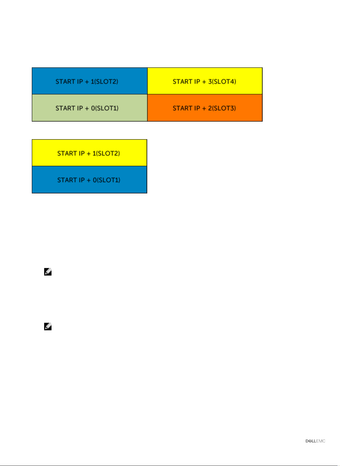
Assigning QuickDeploy IP Address to Servers
The gure here shows the QuickDeploy IP addresses assignment to the servers when there are four half-height servers in VRTX
chassis:
The following gure shows the QuickDeploy IP addresses assignment to the servers when there are two full-height blades in VRTX
chassis:
Modifying iDRAC Network Settings for Individual Server iDRAC
Using this feature, you can congure the iDRAC network congurations settings for each installed server. The initial values displayed
for each of the elds are the current values read from the iDRAC. To use this feature, you must have an Enterprise License.
To modify the iDRAC Network Settings:
1. In the left pane, click Server Overview, and then click Setup. On the Deploy iDRAC page the iDRAC Network Settings
section lists the iDRAC IPv4 and IPv6 network conguration settings of all the installed servers.
2. Modify the iDRAC network settings as required for the server(s).
NOTE: You must select the Enable LAN option to specify the IPv4 or IPv6 settings. For information about the elds,
see the
3. To deploy the setting to iDRAC, click Apply iDRAC Network Settings. Any changes made to the QuickDeploy Settings are also
saved.
The iDRAC Network Settings table reects future network conguration settings; the values shown for installed servers may
or may not be the same as the currently installed iDRAC network conguration settings. Click Refresh to update the iDRAC
Deploy page with each installed iDRAC network conguration settings after changes are made.
NOTE: Changes made to QuickDeploy elds are immediate, but changes made to one or more iDRAC server network
conguration settings may require a couple of minutes to propagate from CMC to iDRAC. Clicking Refresh too soon
may display only partially correct data for a one or more iDRAC servers.
Online Help
.
Modifying iDRAC Network Settings Using RACADM
RACADM config or getconfig commands support the -m <module> option for the following conguration groups:
• cfgLanNetworking
• cfgIPv6LanNetworking
• cfgRacTuning
• cfgRemoteHosts
• cfgSerial
94
Page 95

• cfgSessionManagement
For more information about the property default values and ranges, see the Chassis Management Controller for PowerEdge VRTX
RACADM Command Line Reference Guide available at dell.com/support/manuals.
Conguring iDRAC Virtual LAN Tag Settings
Virtual LAN (VLAN) tags enable multiple VLANs to coexist on the same physical network cable and to segregate the network trac
for security or load management purposes. When you enable the VLAN functionality, each network packet is assigned a VLAN tag.
VLAN tags are chassis properties. They remain with the chassis even when a component is removed.
NOTE: The VLAN ID congured using CMC is applied to iDRAC only when iDRAC is in dedicated mode. If iDRAC is in
shared LOM mode, the VLAN ID changes made in iDRAC are not displayed on the CMC GUI.
Conguring iDRAC Virtual LAN Tag Settings Using RACADM
• Specify the Virtual LAN ID and priority of a particular server with the following command:
racadm setniccfg -m server-<n> -v <VLAN id> <VLAN priority>
The valid values for <n> are 1–4.
The valid values for <VLAN> are 1–4000 and 4021–4094. Default is 1.
The valid values for <VLAN priority> are 0–7. Default is 0.
For example:
racadm setniccfg -m server-1 -v 1 7
For example:
• To remove a server VLAN, disable the VLAN capabilities of the specied server's network:
racadm setniccfg -m server-<n> -v
The valid values for <n> are 1–4.
For example:
racadm setniccfg -m server-1 -v
Conguring iDRAC Virtual LAN Tag Settings Using Web Interface
To congure Vitual LAN(VLAN) for server:
1. Go to any of the following pages:
• In the left pane, click Chassis Overview → Network → VLAN.
• In the left pane, click Chassis Overview → Server Overview and click Setup → VLAN.
2. On the VLAN Tag Settings page, in the iDRAC section, enable VLAN for the server(s), set the priority and enter the ID. For
more information about the elds, see the Online Help.
3. Click Apply to save the settings.
Setting First Boot Device
You can specify the CMC rst boot device for each server. This may not be the actual rst boot device for the server, or may not
even represent a device present in that server. It represents a device sent by CMC to the server and used as its rst boot device of
that server. This device can be set as the default rst-boot device or an one-time device so that you can boot an image to perform
tasks such as running diagnostics or reinstalling an operating system.
You can set the rst boot device for the next boot only or for all subsequent reboots. You can also set the rst boot device for the
server. The system boots from the selected device on the next and subsequent reboots and remains as the rst boot device in the
BIOS boot order, until it is changed again either from the CMC web interface (Chassis Overview → Server Overview → Setup →
First Boot Device) or from the BIOS boot sequence.
95
Page 96

NOTE: The rst boot device setting in CMC web Interface overrides the system BIOS boot settings.
The boot device that you specify must exist and contain a bootable media.
You can set the following devices for rst boot.
Table 18. Boot Devices
Boot Device Description
PXE Boot from a Preboot Execution Environment (PXE) protocol on the Network Interface Card.
Hard Drive Boot from the hard disk drive on the server.
Local CD/DVD Boot from a CD or DVD drive on the server.
Virtual Floppy Boot from the virtual oppy drive. The oppy drive (or a oppy disk image) is on another computer on the
management network, and is attached using the iDRAC GUI console viewer.
Virtual CD/DVD Boot from a virtual CD or DVD drive or CD or DVD ISO image. The optical drive or ISO image le is located on
another computer or boot disk available on the management network and is attached using the iDRAC GUI
console viewer.
Local SD Card Boot from the local SD (Secure Digital) card—for servers that support iDRAC 6 and iDRAC 7 systems only.
Local Floppy Boot from a oppy disk in the local oppy disk drive.
Remote File
Share
Boot from a Remote File Share (RFS) image. The image le is attached using the iDRAC GUI console viewer.
Setting First Boot Device For Multiple Servers Using CMC Web Interface
NOTE: To set the rst boot device for servers, you must have the Server Administrator privileges or Chassis
Conguration Administrator
To set the rst boot device for multiple servers:
1. In the left pane, click Server Overview → Setup → First Boot Device. A list of servers is displayed.
2. In the First Boot Device column, from the drop-down menu corresponding to a server, select the boot device you want to use
for a server.
3. If you want the server to boot from the selected device every time it boots, clear the Boot Once option for the server. If you
want the server to boot from the selected device only on the next boot cycle, select the Boot Once option for the server.
4. Click Apply to save the settings.
privileges, and the iDRAC login privileges.
Setting First Boot Device For Individual Server Using CMC Web Interface
NOTE: To set the rst boot device for servers, you must have Server Administrator privileges or Chassis Conguration
Administrator privileges and iDRAC login privileges.
To set the rst boot device for individual servers:
1. In the left pane, click Server Overview, and then click the server for which you want to set the rst boot device.
2. Go to Setup → First Boot Device. The First Boot Device page is displayed.
3. From the First Boot Device drop-down menu, select the boot device you want to use for each server.
4. If you want the server to boot from the selected device every time it boots, clear the Boot Once option for the server. If you
want the server to boot from the selected device only on the next boot cycle, select the Boot Once option for the server
5. Click Apply to save the settings.
Setting First Boot Device Using RACADM
To set the rst boot device, use the cfgServerFirstBootDevice object.
To enable boot once for a device, use the cfgServerBootOnce object.
96
Page 97

For more information about these objects, see the Chassis Management Controller for PowerEdge VRTX RACADM Command Line
Reference Guide available at dell.com/support/manuals.
Conguring Server FlexAddress
For information about conguring FlexAddress for servers, see Conguring FlexAddress for Chassis-Level Fabric and Slots Using
CMC Web Interface. To use this feature, you must have an Enterprise License.
Conguring Remote File Share
The Remote Virtual Media File Share feature maps a le from a share drive on the network to one or more servers through CMC to
deploy or update an operating system. When connected, the remote le is accessible similar to a le that you can access on a local
server. Two types of media are supported: oppy drives and CD/DVD drives.
To perform a remote le share operation (connect, disconnect, or deploy), you must have the Chassis Conguration Administrator
or Server Administrator privileges. To use this feature, you must have an Enterprise license.
To congure the remote le share:
1. In the left pane, click Server Overview → Setup → Remote File Share.
2. On the Deploy Remote File Share page, type appropriate data in the elds. For more information about the eld descriptions,
see the
3. To connect to a remote le share, click Connect. To connect a remote le share, you must provide the path, user name, and
password. A successful operation allows access to the media.
Click Disconnect to disconnect a previously-connected remote le share.
Click Deploy to deploy the media device.
Online Help.
NOTE: Before you click the Deploy button, make sure that you save all the working les, because this action restarts
the server.
When you click Deploy, the following tasks are executed:
• The remote le share is connected.
• The le is selected as the rst boot device for the servers.
• The server is restarted.
• Power is supplied to the server if the server is turned o.
Conguring Prole Settings Using Server Conguration Replication
The server congurations replicating feature allows you to apply all prole settings from a specied server to one or more servers.
Prole settings that can be replicated are those prole settings which can be modied and are intended to be replicated across
servers. The following three prole groups for servers are displayed and can be replicated:
• BIOS — This group includes only the BIOS settings of a server. These proles are generated from CMC for PowerEdge VRTX
version 1.00 and later.
• BIOS and Boot — This group includes the BIOS and the Boot settings of a server. These proles are generated from CMC for
PowerEdge VRTX version 1.00 and later.
• All Settings — This version includes all the settings of the server and components on that server. These proles are generated
from
– CMC for PowerEdge VRTX version 1.00 and later
– 12th generation servers with iDRAC7 1.00.00 or later and Lifecycle Controller 2 version 1.1 or later
– 13th generation servers with iDRAC8 with Lifecycle Controller 2.00.00.00 or later
The server congurations replication feature supports iDRAC7 and later servers. Earlier generation RAC servers are listed but are
grayed out on the main page, and are not enabled to use this feature.
To use the server congurations replication feature:
97
Page 98

• iDRAC must have the minimum version that is required.
• Server must be powered on.
You can:
• View prole settings on a server or from a saved prole.
• Save a prole from a server.
• Apply a prole to other servers.
• Import stored proles from a management station or remote le share.
• Edit the prole name and description.
• Export stored proles to a management station or remote le share.
• Delete stored proles.
• Deploy selected proles to the target devices using Quick Deploy option.
• Display the log activity for recent server prole tasks.
Accessing Server Proles Page
You can add, manage, and apply server proles to one or more servers using the Server Proles page.
To access the Server Proles page using the CMC web interface, in the left pane, go to Chassis Overview → Server Overview.
Click Setup → Proles. The Server Proles page is displayed.
Adding or Saving Prole
Before copying the properties of a server, rst capture the properties to a stored prole. Create a stored prole and provide a name
and optional description for each prole. You can save a maximum of 16 Stored Proles on the CMC nonvolatile extended storage
media.
NOTE: If a remote share is available, you can store a maximum of 100 proles using the CMC extended storage and
remote share. For more information about the remote share, see
Removing or disabling the nonvolatile extended storage media prevents access to stored prole and disables the Server
Conguration Replication feature.
To add or save a prole:
1. Open the Server Proles page. In the Server Proles section, click Apply and Save Proles.
2. Select the server from whose settings you want to generate the prole, and then click Save Prole.
The Save Prole section is displayed.
3. Select Extended Storage or Network Share as the location to save the prole.
NOTE: The Network Share option is enabled and the details are displayed in the Stored Proles section only if the
network share is mounted and is accessible. If the Network Share is not connected, congure the Network Share for
the chassis. To congure the Network Share, click Edit in the Stored Proles section. For more information about
conguring the network share, see Conguring Network Share Using CMC Web Interface.
4. In the Prole Name and Description elds, type the prole name and description (optional), and then click Save Prole.
NOTE: When saving a Server Prole, the standard ASCII extended character set is supported. However, the
following special characters are not supported:
), “, ., *, >, <, \, /, :, |, #, ?, and ,
CMC communicates with the LC to get the available server prole settings and store them as a named prole.
A progress indicator indicates that the Save operation is in progress. After the action is complete, a message, "Operation
Successful" is displayed.
Conguring Network Share Using CMC Web Interface.
98
NOTE: The process to gather the settings runs in the background. Hence, it may take some time before the new
prole is displayed. If the new prole is not displayed, check the prole log for errors.
Page 99

Applying Prole
Server conguration replication is possible only when server proles are available as stored proles in the nonvolatile media on the
CMC or stored on the remote share. To initiate a server conguration replication operation, you can apply a stored prole to one or
more servers.
NOTE: If a server does not support Dell Lifecycle Controller or the chassis is turned o, you cannot apply a prole to the
server.
To apply a prole to one or more server(s):
1. Go to the Server Proles page. In the Save and Apply Proles section, select the server or servers for which you want to
apply the selected prole.
The Select Prole drop-down menu is enabled.
NOTE: The Select Prole drop-down menu displays all available proles and sorted by type, including those that are
on the remote share and SD card.
2. From the Select Prole drop-down menu, select the prole that you want to apply.
The Apply Prole option is enabled.
3. Click Apply Prole.
A message is displayed that applying a new server prole overwrites the current settings and also restarts the selected servers.
You are prompted to conrm if you want to continue the operation.
NOTE: To perform server cloning operations on servers, the CSIOR option must be enabled for the servers. If CSIOR
option is disabled, a warning message is displayed that CSIOR is not enabled for the servers. To complete the blade
cloning operation, make sure to enable CSIOR option on the servers.
4. Click OK to apply the prole to the selected server.
The selected prole is applied to the server(s) and the server(s) may be restarted immediately, if necessary. For more
information, see the CMC Online Help.
Importing Prole
You can import a server prole that is stored on a management station to CMC.
To import a stored prole from CMC:
1. In the Server Proles page, in the Stored Proles section, click Import Prole.
The Import Server Prole section is displayed.
2. Click Browse to access the prole from the required location and then click Import Prole.
For more information about the elds, see the Online Help.
Exporting Prole
You can export a stored server prole to a specied le folder path on a management station.
To export a stored prole:
1. Go to the Server Proles page. In the Stored Proles section, select the required prole, and then click Export Copy of
Prole.
A File Download message is displayed prompting you to open or save the le.
2. Click Save or Open to export the prole to the required location.
NOTE: If the source prole is on the SD card, a message is displayed indicating that if the prole is exported, then
the description is lost. Press OK to continue exporting the prole.
A message is displayed prompting you to select the destination of the le:
• Local or Network Share if the source le is on an SD card.
99
Page 100

NOTE: The Network Share option is enabled and the details are displayed in the Stored Proles section only if
the network share is mounted and is accessible. If the Network Share is not connected, congure the Network
Share for the chassis. To congure the Network Share, click Edit in the Stored Proles section. For more
information, see Conguring Network Share Using CMC Web Interface.
• Local or SD Card if the source le is on the Network Share.
For more information about the elds, see the Online Help.
3. Select Local, Extended Storage, or Network Share as the destination location based on the options displayed.
• If you select Local, a dialog box appears allowing you to save the prole to a local directory.
• If you select Extended Storage or Network Share, a Save Prole dialog box is displayed.
4. Click Save Prole to save the prole to the selected location.
NOTE: The CMC web interface captures the normal server conguration prole (snapshot of the server), which can be
used for replication on a target system. However, some congurations such as RAID and identity attributes are not
propagated to the new server. For more information on alternate export modes for RAID congurations and identity
attributes, see the white paper,
Server Cloning with Server Conguration Proles
, at DellTechCenter.com.
Editing Prole
You can edit the name and description of a server prole that is stored on the CMC nonvolatile media (SD Card) or the name of a
server prole stored on the remote share.
To edit a stored prole:
1. Go to the Server Proles page. In the Stored Proles section, select the required prole and then click Edit Prole.
The Edit Server Prole — <Prole Name> section is displayed.
2. Edit the prole name and description of the server prole as required and then click Edit Prole.
NOTE: You can edit the prole description only for proles stored on SD cards.
For more information, see the Online Help.
Deleting Prole
You can delete a server prole that is stored on the CMC nonvolatile media (SD Card) or on the Network Share.
To delete a stored prole:
1. In the Server Proles page, in the Stored Proles section, select the required prole and then click Delete Prole.
A warning message is displayed indicating that deleting a prole would permanently delete the selected prole.
2. Click OK to delete the selected prole.
For more information, see the Online Help.
Viewing Prole Settings
To view Prole settings for a selected server, go to the Server Proles page. In the Server Proles section, click View in the Server
column for the required server. The View Settings page is displayed.
Prole
For more information about the displayed settings, see the Online Help.
NOTE: The CMC Server Conguration Replication feature retrieves and displays the settings for a specic server, only if
the Collect System Inventory on Restart (CSIOR) option is enabled.
To enable CSIOR on:
• 12th generation servers — After restarting the server, when the company logo is displayed, select F2. On the iDRAC Settings
page, in the left pane, click Lifecycle Controller, and then click CSIOR to enable the changes.
100
 Loading...