

Page 1

Dell EMC ML3 Tape Library
User's Guide
Page 2

Page 3

Information in this document is subject to change without notice.
Copyright © 2017 Dell Inc. or its subsidiaries. All rights reserved.
Dell, EMC, and other trademarks are trademarks of Dell Inc. or its subsidiaries. Other trademarks may
be trademarks of their respective owners.
Printed December 2017
iii
Page 4

iv Dell EMC ML3 Tape Library: User's Guide
Page 5

Contents
iii
Figures .............. vii
Tables ............... ix
Read this first ............ xi
Minimum firmware levels for common library
features ................ xi
Contacting Dell ............. xii
Safety and environmental notices ... xiii
Danger and Caution notices ........ xiii
Possible safety hazards .......... xvi
Class I laser product ........... xvi
Performing the safety inspection procedure ... xvii
Rack safety .............. xvii
Power Cords.............. xix
Preface .............. xxi
Overview .............. 1
Introduction .............. 1
Structure and supported library configurations ... 2
Components ............. 7
Front panel ............. 7
Rear panel ............. 8
Magazines ............. 9
Power supply............ 11
Bar code reader ........... 11
User interfaces ............. 11
Supported tape drives ........... 12
Control path drives ........... 12
Mixed drives ............. 12
Drive sled back panels.......... 13
Physical and logical addresses of drives .... 15
Supported tape cartridges ......... 16
Library functions ............ 17
Encryption ............. 17
Library sharing ............ 17
Path failover and load balancing ...... 18
Alerts and logging ........... 19
Host connectivity ............ 20
Network connectivity ........... 20
Planning .............. 23
Library Layout and Location requirements .... 23
Power cords .............. 25
Network requirements........... 30
Host requirements ............ 31
Installing .............. 33
Unpacking the Base Module and Expansion
Modules ............... 34
Identifying Library Module components ..... 39
Preparing top and bottom modules ...... 39
Installing modules in a rack ......... 42
Installing a tabletop module ......... 46
Aligning and connecting modules ....... 46
Validating tape drive installation ....... 49
Connecting cables ............ 49
Powering on the library .......... 51
The Initial Setup process .......... 52
Initial configuration and customization ..... 53
Labeling and loading tape cartridges ...... 53
Verifying the installation .......... 55
Advanced library configuration........ 55
Overview .............. 56
Library partitioning .......... 57
Verifying the host connection ........ 58
Managing ............. 59
The Management GUI ........... 59
The Operator Panel ............ 61
Locating Management functions ....... 63
Default settings ............ 66
Methods of cleaning drives ........ 69
Accessing cartridges .......... 70
Configuring Library Managed Encryption (KMIP) 70
Troubleshooting........... 73
Finding event information ......... 73
Identifying a failed component ........ 73
Running library tests ........... 73
Troubleshooting Guide .......... 73
Pre-call checklist ............. 76
Contacting Dell ............. 77
Diagnostic information .......... 77
The ITDT firmware update, dump retrieval and
drive test tool ............ 77
Event codes ............. 78
Main error events .......... 79
Warning error events ......... 86
Configuration Change events ...... 93
Informational events ......... 94
TapeAlert flags ............ 95
TapeAlert flags supported by the library... 95
TapeAlert flags supported by the drive ... 97
Sense data ............. 100
Drive Error Codes: Single-character display
(SCD) ............... 100
SCD dot ............. 102
Status light ............ 102
Upgrading and servicing ...... 105
Internal view of library .......... 105
v
Page 6

Adding, removing, or replacing a tape drive ... 106
Adding or replacing a Base or Expansion Module 109
Adding, removing, or replacing a power supply 114
Replacing a Base or Expansion controller card .. 117
Installing, removing, or replacing an accessor and
spooling mechanism ........... 120
Returning the accessor to the Base Module .. 127
Removing or replacing a spooling mechanism .. 129
Removing or replacing a magazine ...... 133
Moving the library modules ........ 135
Appendix A. Library Configuration
Forms .............. 137
Library information ........... 138
Module and drive information ....... 139
Logical Library information ........ 140
Users account information ......... 141
Appendix B. LTO media ....... 143
Data cartridges ............. 143
Cartridge Read/Write compatibility ..... 144
WORM (Write Once, Read Many) cartridges ... 144
WORM media ............ 144
Data security on WORM media ...... 145
WORM media errors .......... 145
Cleaning cartridge............ 145
Labeling tape cartridges .......... 145
Guidelines for bar code labels ....... 147
Write-Protect switch ........... 147
Handling the cartridges .......... 148
Providing training ........... 148
Ensuring proper packaging ........ 148
Proper acclimation and environmental
conditions ............. 149
Completing a thorough inspection ..... 150
Handling the cartridge carefully ...... 150
Environmental and shipping specifications for tape
cartridges .............. 151
Appendix C. Accessibility ...... 153
Glossary ............. 155
Index ............... 175
vi Dell EMC ML3 Tape Library: User's Guide
Page 7

Figures
1. Two module tape library ........ 1
2. Base Module ............ 2
3. Expansion Module .......... 3
4. Base Module ............ 3
5. 2 module library ........... 3
6. 3 module library ........... 3
7. 4 module library ........... 4
8. 5 module library ........... 4
9. 6 Module library ........... 5
10. 7 module library ........... 6
11. Front panel ............. 7
12. Rear panel ............. 8
13. Physical numbering of modules ...... 9
14. Left magazine ............ 10
15. Right magazine ........... 10
16. Power supply rear panel LEDs ...... 11
17. Mixed drives in a logical library ..... 13
18. Drive sled indicators ......... 13
19. Half-height SAS dual port........ 14
20. Half-height FC single port ....... 14
21. Full-height FC dual port ........ 15
22. Physical numbering of drives ...... 16
23. Types of receptacles .......... 30
24. Removing the module from the box .... 34
25. The module after removal from the box 35
26. Unlatching the top of the module ..... 36
27. Removing the top of the module ..... 36
28. The module is opened to show the foam
packing............... 37
29. The foam packing is removed, and the internal
components are shown - Base Module. ... 37
30. Top cover sensor ........... 38
31. Incorrect top cover insertion - too high 38
32. Correct top cover insertion ....... 39
33. Lowering the front of the top cover .... 40
34. Unlocking the spring loaded lock ..... 41
35. Removing the cover.......... 41
36. Lifting the cover and locking it ...... 42
37. Universal rack connector ........ 43
38. Incorrect connector locations ....... 43
39. Correct connector locations ....... 44
40. Mounting the rails to the connectors .... 44
41. Side rails installed .......... 45
42. Sliding the library into the rack ...... 45
43. Library in the rack .......... 46
44. Alignment lever lock ......... 47
45. Alignment lever locked or engaged to lower
module .............. 47
46. Alignment lever unlocked or disengaged 48
47. Two modules in rack, seen from the rear 48
48. Connected modules .......... 49
49. Full-height FC dual port ........ 50
50. Half-height FC single port ....... 50
51. Half-height SAS dual port........ 51
52. IP address selection .......... 52
53. Open I/O station seen from the left .... 54
54. Magazine pulled out ......... 55
55. Management GUI main screen ...... 60
56. Operator Panel main screen ....... 62
57. Front panel LEDs .......... 63
58. Internal view of the library ....... 105
59. Drive bay covers .......... 107
60. Alignment rails ........... 107
61. Installing a tape drive......... 108
62. Unlocking the drive ......... 108
63. Interconnect cables .......... 111
64. Unlocking or disengaging the alignment lever 112
65. Loosening the thumbscrews....... 113
66. Sliding the module out of the rack .... 113
67. Power supplies ........... 115
68. Sliding in the new power supply ..... 116
69. Controller card components ....... 118
70. Installing a Controller card ....... 119
71. Magazine release levers ........ 121
72. Unlocking the robot ......... 122
73. Finger holes ............ 122
74. Unlocking the spooling cable and placing it in
its cradle ............. 123
75. Spooling cable in park position ..... 124
76. Pins are aligned horizontally ...... 125
77. Installing the spooling cable ...... 126
78. Inserting the screwdriver to manually operate
the accessor ............ 128
79. Left magazine opening ........ 128
80. Unlocking the spooling mechanism .... 130
81. Unlocked spooling mechanism - enlarged
view .............. 131
82. Locked spooling mechanism - enlarged view 132
83. Removing the spooling mechanism .... 133
84. Manually releasing the right magazine 134
85. Manually releasing the left magazine 134
86. The LTO data cartridge ........ 143
87. LTO Data and WORM tape cartridges 145
88. Sample bar code label on the LTO 8 Tape
Cartridge ............. 147
89. Setting the write-protect switch ..... 148
90. Double-boxing tape cartridges for shipping 149
91. Checking for gaps in the seams of a cartridge 150
vii
Page 8

viii Dell EMC ML3 Tape Library: User's Guide
Page 9

Tables
1. Regulatory marks .......... xi
2. Minimum firmware levels for common library
features .............. xi
3. Module designations .......... 1
4. Minimum and maximum storage configurations 2
5. Library configurations ......... 3
6. Front panel descriptions......... 7
7. Rear panel descriptions ......... 8
8. Physical numbering of storage slots - bottom
module .............. 10
9. Power supply LEDs .......... 11
10. Supported tape drives ......... 12
11. Drive sled indicators ......... 13
12. Half-height SAS dual port........ 14
13. Half-height FC single port ....... 14
14. Full-height FC dual port ........ 15
15. Differences between CPF and DPF ..... 18
16. Location requirements ......... 23
17. Physical specifications ......... 24
18. Electrical specifications ......... 24
19. Equipment environmental specifications 24
20. Gas and particulate exposure ...... 25
21. Power cords ............ 26
22. Installation Precautions ........ 33
23. Full-height FC dual port ........ 50
24. Half-height FC single port ....... 50
25. Half-height SAS dual port........ 51
26. Main screen elements ......... 60
27. Navigation Dock ........... 61
28. Status icons ............ 61
29. Operator Panel menu tree........ 62
30. Front panel LEDs .......... 63
31. Locating Management functions ..... 63
32. Default settings ........... 66
33. Magazine state ........... 70
34. Resolving errors ........... 73
35. Main error events .......... 79
36. Warning events ........... 86
37. Configuration Change events ...... 93
38. Informational Events ......... 94
39. Error codes on the single-character display 101
40. Meaning of Status light and single-character
display (SCD) ........... 102
41. Internal view description ....... 105
42. Pinch hazard............ 106
43. Power supply components ....... 115
44. Controller card components ....... 118
45. Cartridge data capacity and recording formats 143
46. Nominal cartridge life: Load/unload cycles 144
47. Data cartridge compatibility with LTO tape
drive .............. 144
48. Cartridges and VOLSERs compatible with the
LTO Tape Drives .......... 146
49. Location of the write-protect switch .... 148
50. Environment for operating, storing, and
shipping the LTO Ultrium Tape Cartridge .. 151
ix
Page 10

x Dell EMC ML3 Tape Library: User's Guide
Page 11
Read this first
Regulatory information
v The library must be installed in a restricted area.
v Only personnel with technical and product safety training should have access to the library.
v To comply with the regulations and standards, the library must be properly installed in an office or
industrial environment with shielded cables and adequate grounding of SAS interface and input
power.
v Models: 3555-L3A, 3555-E3A
Table 1. Regulatory marks
The CE mark is a mandatory conformity mark on many products that are
placed on the single market in the European Economic Area (EEA). The
CE marking certifies that a product meets EU consumer safety, health, or
environmental requirements.
CSA C22-2 No.60950-1 - Electrical safety - UL 60950-1 68475
Minimum firmware levels for common library features
Table 2. Minimum firmware levels for common library features
Feature Minimum Firmware Levels Required
LTO8 (HH/FH) Tape Drives Library Firmware must be at 1.1.1.0 or greater to support
the LTO8 tape drives. Ensure that any host applications
and device drivers are at the minimum level that is
required to support LTO8 tape drives.
LTO6 (HH/FH) and LTO7 (HH/FH) Tape Drives Library Firmware must be at 1.1.0.1-A00 or greater to
support the LTO6 and LTO7 tape drives. Ensure that any
host applications and device drivers are at the minimum
level that is required to support LTO6 and LTO7 tape
drives.
Library Managed Encryption Library Firmware must be at 1.1.1.0-A00 or greater to
support the Library Managed Encryption feature. Ensure
that any key manager applications are at the minimum
level that is required to support the 3U library.
Path Failover (Control Path and Data Path) Library Firmware must be at 1.1.1.0-A00 or greater to
support the Path Failover feature. Ensure that any device
drivers are at the minimum level that is required to
support the 3U library.
xi
Page 12

Table 2. Minimum firmware levels for common library features (continued)
Feature Minimum Firmware Levels Required
Remote Logging (rsyslog) Library Firmware must be at 1.1.1.0-A00 or greater to
support the Remote Logging feature. Ensure that any
device drivers are at the minimum level that is required
to support the 3U library.
Contacting Dell
For customers in the United States, call 800-WWW-DELL (800-999-3355).
Note: If you do not have an active Internet connection, you can find contact information about your
purchase invoice, packing slip, bill, or Dell product catalog.
Dell provides online and telephone-based support and service options. Service availability varies by
country and product, and some services might not be available in your area. To contact Dell for sales,
technical support, or customer service issues follow the steps that are listed:
1. Go to www.Dell.com/support.
2. Select your country from the drop-down menu on the lower right corner of the page.
3. For customized support:
a. Enter your system Service Tag in the Enter your Service Tag field.
b. Click Submit. The support page that lists the various support categories is displayed.
4. For general support:
a. Select your product category.
b. Select your product segment.
c. Select your product. The support page that lists the various support categories is displayed.
5. For contact details of Dell Global Technical Support:
a. Click Global Technical Support.
b. The Contact Technical Support page is displayed with details to call, chat, or e-mail the Dell
Global Technical Support team.
xii Dell EMC ML3 Tape Library: User's Guide
Page 13

Safety and environmental notices
When this product is used, observe the danger, caution, and attention notices that are contained in this
guide. The notices are accompanied by symbols that represent the severity of the safety condition.
The sections that follow define each type of safety notice and give examples.
Danger and Caution notices
Danger notices
A danger notice calls attention to a situation that is potentially lethal or extremely hazardous to people. A
lightning bolt symbol always accompanies a danger notice to represent a dangerous electrical condition.
xiii
Page 14
To prevent a possible shock from touching two surfaces with different
protective ground (earth), use one hand, when possible, to connect or
disconnect signal cables. (D001)
Overloading a branch circuit is potentially a fire hazard and a shock hazard
under certain conditions. To avoid these hazards, ensure that your system
electrical requirements do not exceed branch circuit protection requirements.
Refer to the information that is provided with your device or the power
rating label for electrical specifications. (D002)
If the receptacle has a metal shell, do not touch the shell until you have
completed the voltage and grounding checks. Improper wiring or grounding
could place dangerous voltage on the metal shell. If any of the conditions
are not as described, STOP. Ensure the improper voltage or impedance
conditions are corrected before proceeding. (D003)
An electrical outlet that is not correctly wired could place hazardous voltage
on metal parts of the system or the devices that attach to the system. It is
the responsibility of the customer to ensure that the outlet is correctly wired
and grounded to prevent an electrical shock. A lightning bolt symbol always
accompanies a danger notice to represent a dangerous electrical condition.
(D004)
When working on or around the system, observe the following precautions:
Electrical voltage and current from power, telephone, and communication
cables are hazardous. To avoid a shock hazard:
v If Dell supplied a power cord(s), connect power to this unit only with the
Dell provided power cord. Do not use the Dell provided power cord for
any other product.
v Do not open or service any power supply assembly.
v Do not connect or disconnect any cables or perform installation,
maintenance, or reconfiguration of this product during an electrical storm.
v The product might be equipped with multiple power cords. To remove all
hazardous voltages, disconnect all power cords.
v Connect all power cords to a properly wired and grounded electrical
outlet. Ensure that the outlet supplies proper voltage and phase rotation
according to the system rating plate.
v Connect any equipment that will be attached to this product to properly
wired outlets.
v When possible, use one hand only to connect or disconnect signal cables.
v Never turn on any equipment when there is evidence of fire, water, or
structural damage.
v Do not attempt to switch on power to the machine until all possible
unsafe conditions are corrected.
v Assume that an electrical safety hazard is present. Perform all continuity,
grounding, and power checks specified during the subsystem installation
procedures to ensure that the machine meets safety requirements.
v Do not continue with the inspection if any unsafe conditions are present.
v Disconnect the attached power cords, telecommunications systems,
networks, and modems before you open the device covers, unless
instructed otherwise in the installation and configuration procedures.
v Connect and disconnect cables as described in the following procedures
when installing, moving, or opening covers on this product or attached
devices.
xiv Dell EMC ML3 Tape Library: User's Guide
Page 15
To disconnect:
1. Turn off everything (unless instructed otherwise).
2. Remove the power cords from the outlets.
3. Remove the signal cables from the connectors.
4. Remove all cables from the devices.
To connect:
1. Turn off everything (unless instructed otherwise).
2. Attach all cables to the devices.
3. Attach the power cords to the outlets.
4. Turn on the devices.
v Sharp edges, corners and joints may be present in and around the system.
Use care when handling equipment to avoid cuts, scrapes and pinching.
(D005)
Heavy equipment - personal injury or equipment damage might result if
mishandled. (D006)
DANGER: Multiple power cords. The product might be equipped with
multiple power cords. To remove all hazardous voltages, disconnect all
power cords. (L003)
Caution notices
A caution notice calls attention to a situation that is potentially hazardous to people because of some
existing condition, or to a potentially dangerous situation that might develop because of some unsafe
practice.
The doors and covers to the product are to be closed at all times except for
service by trained service personnel. All covers must be replaced and doors
closed at the conclusion of the service operation. (C013)
This product is equipped with a 3-wire (two conductors and ground) power
cable and plug. Use this power cable with a properly grounded electrical
outlet to avoid electrical shock. (C018)
This assembly contains mechanical moving parts. Use care when servicing
this assembly. (C025)
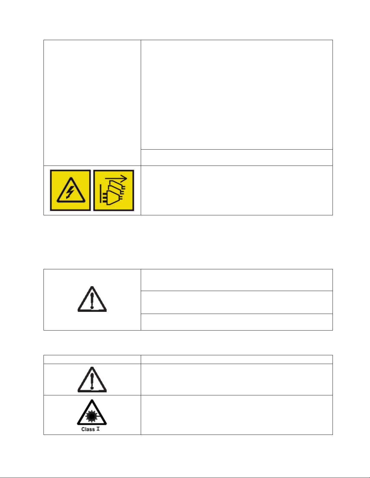
A caution notice can be accompanied by one of several symbols:
If the symbol is... It means...
A generally hazardous condition not represented by other safety symbols.
A hazardous condition due to the use of a laser in the product. Laser
symbols are always accompanied by the classification of the laser as defined
by the U. S. Department of Health and Human Services (for example, Class
I, Class II, and so forth).
Safety and environmental notices xv
Page 16
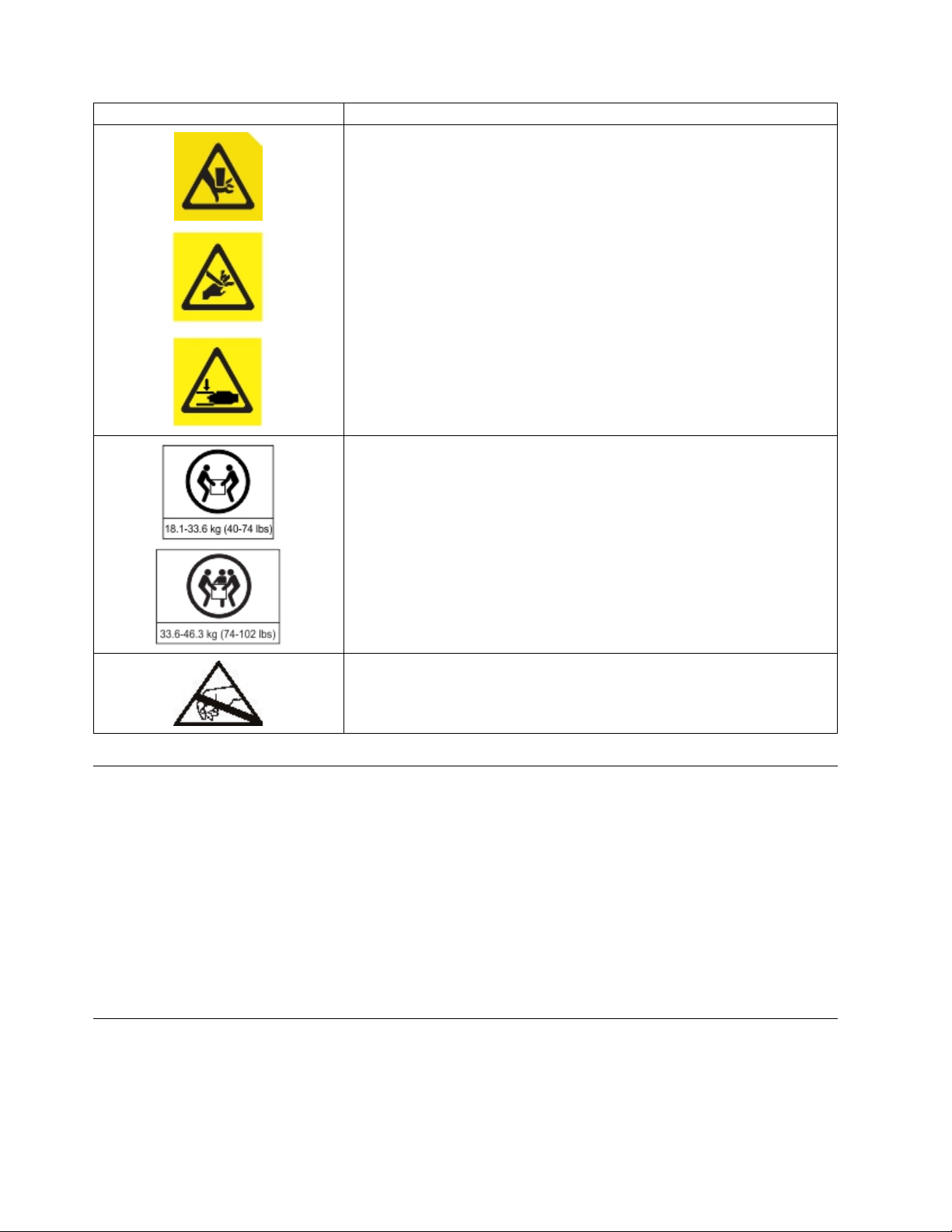
If the symbol is... It means...
Risk of hand pinching, can trap hands, fingers and cause serious injury.
Keep hands clear during operation (L012).
The weight of this part or unit is between 18.1 and 33.6 kg (40 and 74 lb). It
takes two persons to safely lift this part or unit. (C009)
The weight of this part or unit is between 33.6 and 46.3 kg (74 and 102 lb).
It takes three persons to safely lift this part or unit. (C010)
A hazardous condition due to the unit's susceptibility to electrostatic
discharge.
Possible safety hazards
Possible safety hazards to the operation of this product are:
Electrical
An electrically charged frame can cause serious electrical shock.
Mechanical
Hazards (for example, a safety cover missing) are potentially harmful to people.
Chemical
Do not use solvents, cleaners, or other chemicals that are not approved for use on this product.
Before the library is used, repair any of the preceding problems.
Class I laser product
Before the library is used, review the following laser safety information.
xvi Dell EMC ML3 Tape Library: User's Guide
Page 17
The product might contain a laser assembly that complies with the performance standards set by the US
Food and Drug Administration for a Class I laser product. Class I laser products do not emit hazardous
laser radiation. The product has the necessary protective housing and scanning safeguards to ensure that
laser radiation is inaccessible during operation or is within Class I limits. External safety agencies
reviewed the product and obtained approvals to the latest standards as they apply.
Performing the safety inspection procedure
Before you service the unit, complete the following safety inspection procedure.
1. Stop all activities between the host and the library’s tape drives.
2. Turn off the power to the library by pushing in the Power button on the front of the tape library for 4
seconds.
3. Unplug the library’s power cord from the electrical outlet and the library’s power supply unit.
4. Check the library’s power cords for damage, such as a pinched, cut, or frayed cord.
5. If drives are FC/SAS attached, check the tape drive's FC/SAS cable for damage.
6. Check the top and bottom covers of the library for sharp edges, damage, or alterations that expose its
internal parts.
7. Check the top and bottom covers of the library for proper fit. They must be in place and secure.
8. Check the product label at the rear of the library to make sure that it matches the voltage at your
outlet.
Rack safety
The following general safety information must be used for all rack-mounted devices.
DANGER
Observe the following precautions when working on or around your IT rack system.
v Heavy equipment - personal injury or equipment damage might result if mishandled.
v Always lower the leveling pads on the rack cabinet.
v Always install stabilizer brackets on the rack cabinet.
v To avoid hazardous conditions due to uneven mechanical loading, always install the heaviest devices
in the bottom of the rack cabinet. Always install servers and optional devices starting from the bottom
of the rack cabinet.
v Rack-mounted devices are not to be used as shelves or work spaces. Do not place objects on top of
rack-mounted devices.
v Each rack cabinet might have more than one power cord. Be sure to disconnect all power cords in the
rack cabinet when directed to disconnect power during servicing.
v Connect all devices installed in a rack cabinet to power devices installed in the same rack cabinet. Do
not plug a power cord from a device installed in one rack cabinet into a power device installed in a
different rack cabinet.
Safety and environmental notices xvii
Page 18
v An electrical outlet that is not correctly wired could place hazardous voltage on the metal parts of the
system or the devices that attach to the system. It is the responsibility of the customer to ensure that
the outlet is correctly wired and grounded to prevent an electrical shock. (R001 part 1 of 2)
Caution
v Do not install a unit in a rack where the internal rack ambient temperatures might exceed the
manufacturer's recommended ambient temperature for all your rack-mounted devices.
v Do not install a unit in a rack where the air flow is compromised. Ensure that air flow is not blocked
or reduced on any side, front, or back of a unit that is used for air flow through the unit.
v Consideration must be given to the connection of the equipment to the supply circuit so that
overloading of the circuits does not compromise the supply wiring or overcurrent protection. To
provide the correct power connection to a rack, refer to the rating labels on the equipment in the rack
to determine the total power requirement of the supply circuit.
v (For sliding drawers) Do not pull out or install any drawer or feature if the rack stabilizer brackets are
not attached to the rack. Do not pull out more than one drawer at a time. The rack might become
unstable if you pull out more than one drawer at a time.
v (For fixed drawers) This drawer is a fixed drawer and must not be moved for servicing unless
specified by the manufacturer. Attempting to move the drawer partially or out of the rack might cause
the rack to become unstable or cause the drawer to fall out of the rack. (R001 part 2 of 2)
Caution
Removing components from the upper positions in the rack cabinet improves rack stability during
relocation. Follow these general guidelines whenever you relocate a populated rack cabinet within a room
or building:
v Reduce the weight of the rack cabinet by removing equipment, starting at the top of the rack cabinet.
When possible, restore the rack cabinet to the configuration of the rack cabinet as you received it. If
this configuration is not known, you must do the following:
– Remove all devices in the 32U position (compliance ID RACK-001) or 22U (compliance ID RR001)
and above.
– Ensure that the heaviest devices are installed in the bottom of the rack cabinet.
xviii Dell EMC ML3 Tape Library: User's Guide
Page 19

– Ensure that there are little-to-no empty U-levels between devices installed in the rack-cabinet below
the 32U (compliance ID RACK-001) or 22U (compliance ID RR001) level, unless the received
configuration specifically allowed it.
v If the rack cabinet you are relocating is part of a suite of rack cabinets, detach the rack cabinet from the
suite.
v If the rack cabinet you are relocating was supplied with removable outriggers, they must be reinstalled
before the cabinet is relocated.
v Inspect the route that you plan to take to eliminate potential hazards.
v Verify that the route that you choose can support the weight of the loaded rack cabinet. Refer to the
documentation that comes with your rack cabinet for the weight of a loaded rack cabinet.
v Verify that all door openings are at least 760 x 2032 mm (30 x 80 in.).
v Ensure that all devices, shelves, drawers, doors, and cables are secure.
v Ensure that the four leveling pads are raised to their highest position.
v Ensure that no stabilizer bracket is installed on the rack cabinet during movement.
v Do not use a ramp that is inclined at more than 10 degrees.
v When the rack cabinet is in the new location, complete these steps.
– Lower the four leveling pads.
– Install stabilizer brackets on the rack cabinet.
– If you removed any devices from the rack cabinet, repopulate the rack cabinet from the lowest
position to the highest position.
v If a long-distance relocation is required, restore the rack cabinet to the configuration of the rack cabinet
as you received it. Pack the rack cabinet in the original packaging material, or equivalent. Also, lower
the leveling pads to raise the casters off the pallet and bolt the rack cabinet to the pallet. (R002)
Power Cords
For your safety, Dell provides a power cord with a grounded attachment plug to use with this Dell
product. To avoid electrical shock, always use the power cord and plug with a properly grounded outlet.
Dell power cords used in the United States and Canada are listed by Underwriter’s Laboratories (UL)
and certified by the Canadian Standards Association (CSA).
For units intended to be operated at 115 volts: Use a UL-listed and CSA-certified cord set consisting of a
minimum 18 AWG, Type SVT or SJT, three-conductor cord, a maximum of 15 feet in length and a parallel
blade, grounding-type attachment plug rated 15 amperes, 125 volts.
For units intended to be operated at 230 volts (U.S. use): Use a UL-listed and CSA-certified cord set
consisting of a minimum 18 AWG, Type SVT or SJT, three-conductor cord, a maximum of 15 feet in
length and a tandem blade, grounding-type attachment plug rated 15 amperes, 250 volts.
For units intended to be operated at 230 volts (outside the U.S.): Use a cord set with a grounding-type
attachment plug. The cord set should have the appropriate safety approvals for the country in which the
equipment will be installed.
Dell power cords for a specific country or region are usually available only in that country or region.
Safety and environmental notices xix
Page 20

xx Dell EMC ML3 Tape Library: User's Guide
Page 21

Preface
This manual contains information and instructions necessary for the installation, operation, and service of
the Dell™EMC ML3 Tape Library.
Related Publications
Refer to the following publications for more information.
v Dell™EMC ML3 Tape Library Getting Started Guide provides unpacking and initial setup information.
v IBM Security Key Lifecycle Manager Knowledge Center, which is located at http://www-01.ibm.com/
support/knowledgecenter/SSWPVP/welcome?lang=en, contains information to help you install,
configure, and use the IBM®Security Key Lifecycle Manager.
xxi
Page 22

xxii Dell EMC ML3 Tape Library: User's Guide
Page 23
Overview
Introduction
The Dell™EMC ML3 Tape Library provides compact, high-capacity, low-cost solutions for simple,
unattended data backup. The installation begins with the 3U high Base Module, with capacity for 32 tape
cartridges and 3 half-height LTO tape drives, or one full-height and one half-height tape drive.
Each module type has its special designation.
Table 3. Module designations
Product Description
Dell EMC ML3 Base Module
Dell EMC ML3E Expansion Module
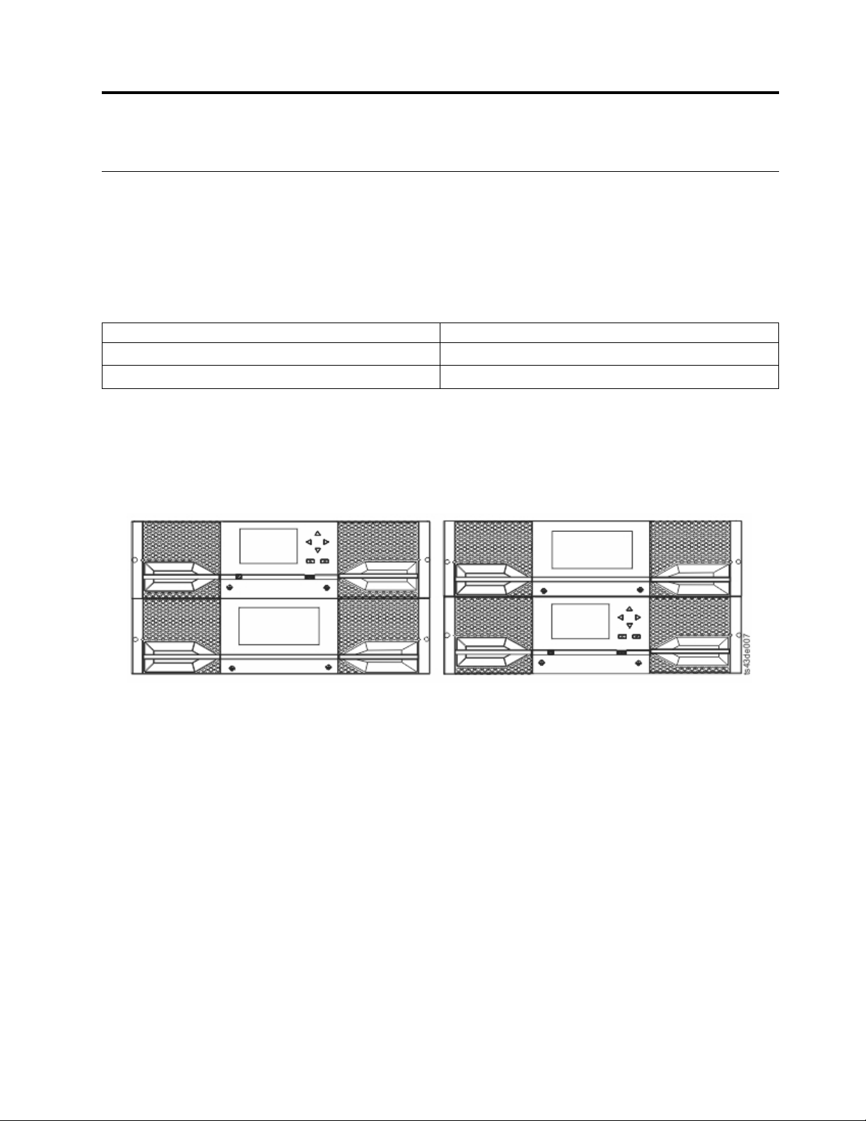
Figure 1 shows a two-module version of the tape library. The library on the left shows the base module
above the expansion module. The library on the right shows the base module below the expansion
module. An individual library can consist of one base module and up to 6 expansion modules. See
“Structure and supported library configurations” on page 2 for supported configurations.
Figure 1. Two module tape library
The library provides the following capabilities:
v New user interface for improved usability
v Updated library communication system
v I/O magazines to allow individual cartridge handling to be done independent of the library.
v Mixed media types
v Integrated management tools
v Scalability to seven modules
v Remote management with the management GUI
v Remote monitoring with Simple Network Management Protocol (SNMP)
v Multipath architecture
v Host-based path failover
v Graphical management interface
1
Page 24
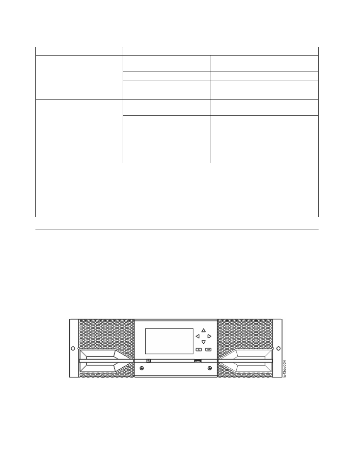
Table 4. Minimum and maximum storage configurations
Configuration Capacity
Cartridges
Minimum
1 Module Library
Base Module only
Maximum
7 Module Library
Base Module
6 Expansion Modules
Notes:
v1A single module (or the lowest module in a library) can have a 4-slot I/O Station. The lowest slot is inaccessible
to the accessor.
v2HH = Half height. FH = Full height.
v3Every module except the lowest one can contain a 5-slot I/O Station. If a seven Module library has an I/O
Station for each module, the maximum number of slots that can be configured as I/O slots are 34 (six modules
with 5-slot I/O Stations, and the lowest module with a 4-slot I/O Station).
HH2Tape Drives 3
FH2Tape Drives 1
HH/FH Tape Drive Mix 1/1
Cartridges
HH Tape Drives 21
FH Tape Drives 7
HH/FH Tape Drive Mix
28 with 4-slot I/O Station enabled
268 with one 4-slot I/O Station enabled
Nineteen half-height drives
to one full-height drive, or
Seven half-height drives
to seven full-height drives
32
272
1
3
Structure and supported library configurations
Supported library configurations
The library supports a single base module tabletop configuration or a scalable rackmount configuration.
All libraries start with a Base Module. Up to six Expansion Modules can be added as needed to support
customer requirements. The architecture is designed to support a maximum of three Expansion Modules
above the Base Module and three Expansion Modules below the Base Module. Table 5 on page 3 shows
the supported configurations for libraries, ranging 1 - 7 total modules.
Figure 2. Base Module
2 Dell EMC ML3 Tape Library: User's Guide
Page 25
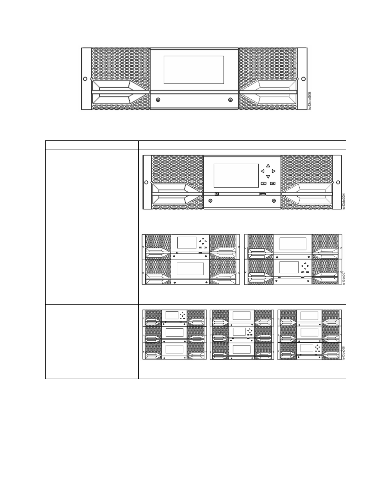
Figure 3. Expansion Module
Table 5. Library configurations
Module quantity Supported library configuration
1 module library
Base Module only
Figure 4. Base Module
2 module library
Base Module, and
1 Expansion Module
Figure 5. 2 module library
3 module library
Base Module, and
2 Expansion Modules
Figure 6. 3 module library
Overview 3
Page 26
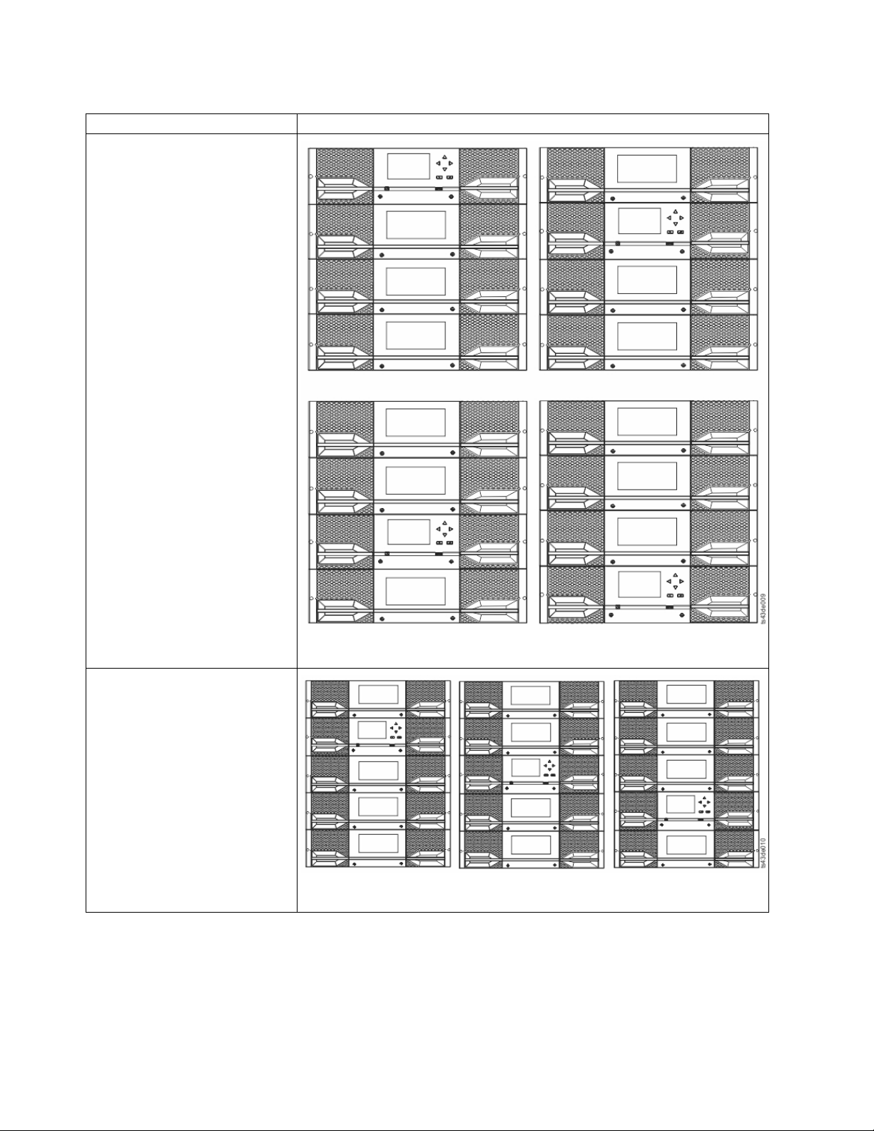
Table 5. Library configurations (continued)
Module quantity Supported library configuration
4 module library
Base Module, and
3 Expansion Modules
5 module library
Base Module, and
4 Expansion Modules
Figure 7. 4 module library
Figure 8. 5 module library
4 Dell EMC ML3 Tape Library: User's Guide
Page 27
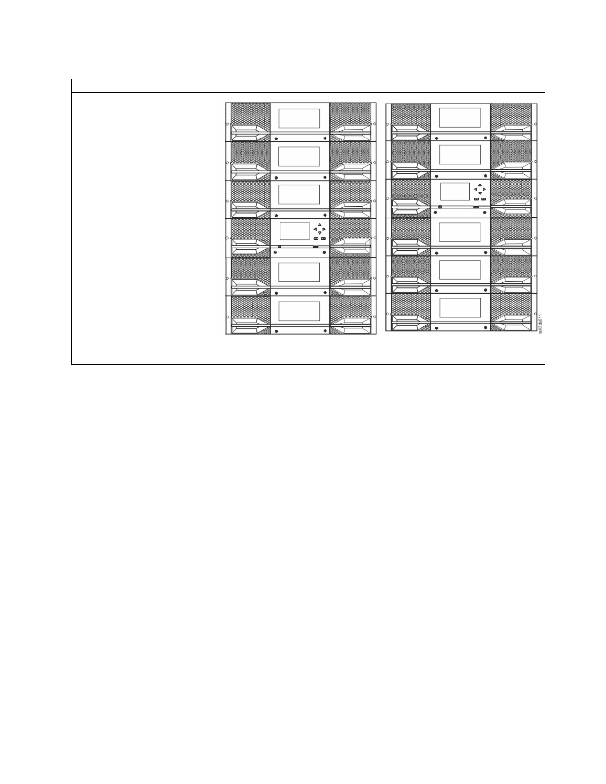
Table 5. Library configurations (continued)
Module quantity Supported library configuration
6 module library
Base Module, and
5 Expansion Modules
Figure 9. 6 Module library
Overview 5
Page 28
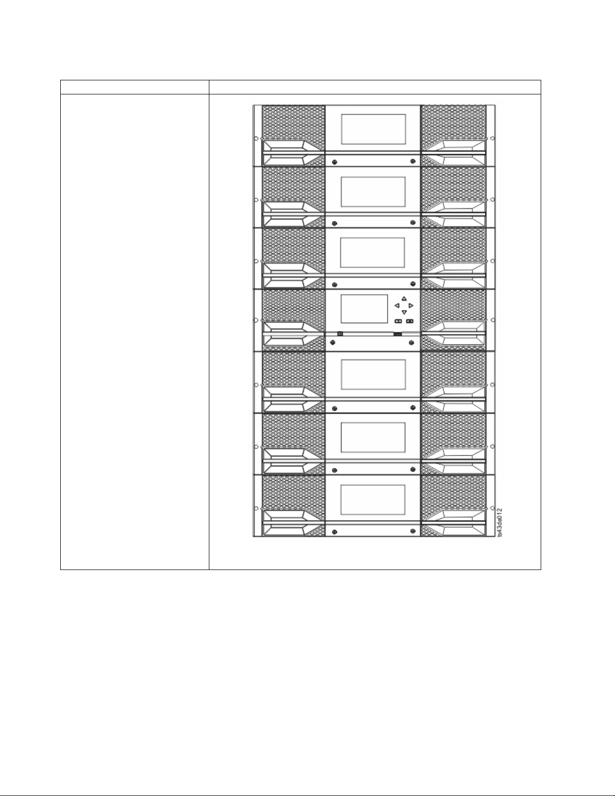
Table 5. Library configurations (continued)
Module quantity Supported library configuration
7 module library
Base Module, and
6 Expansion Modules
Figure 10. 7 module library
6 Dell EMC ML3 Tape Library: User's Guide
Page 29
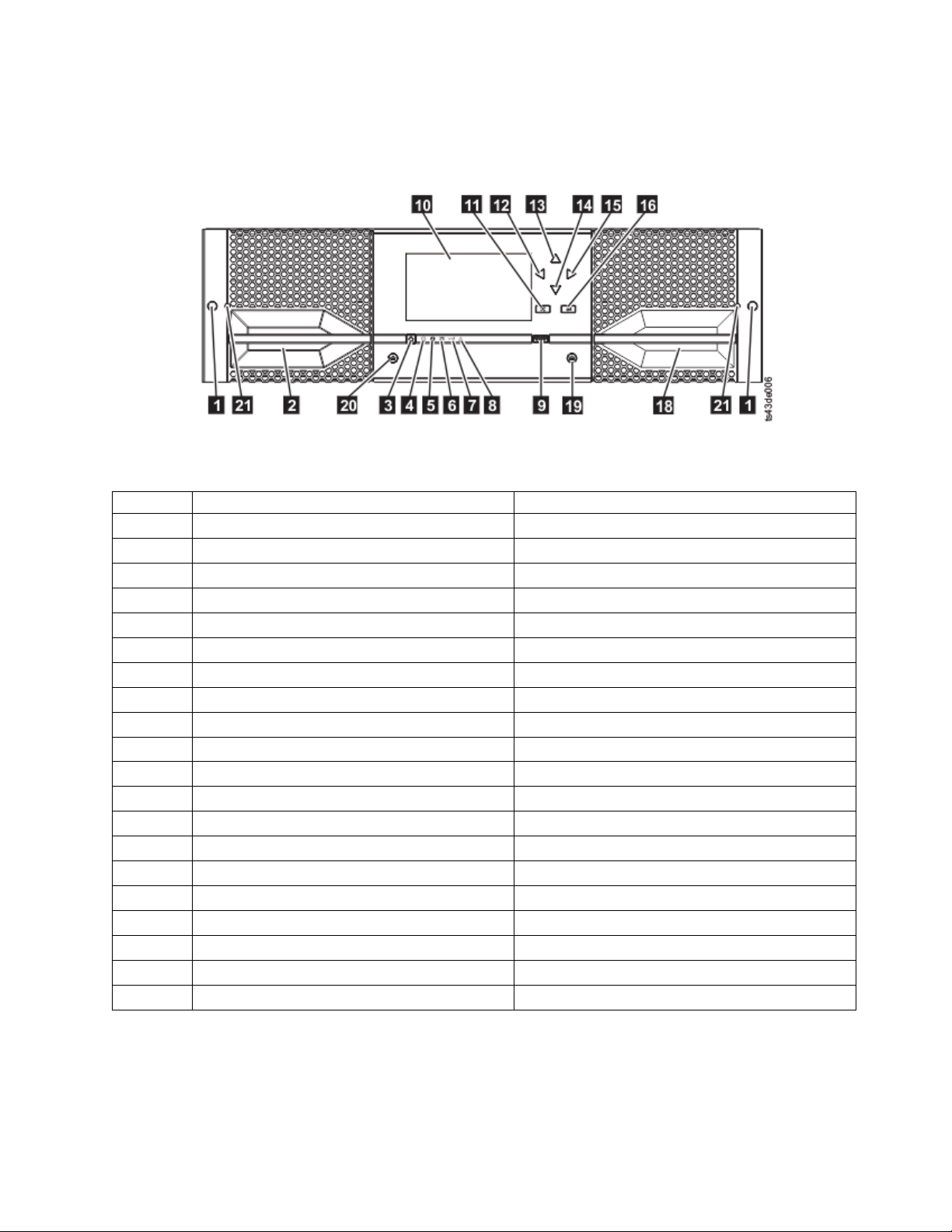
Components
Front panel
Figure 11. Front panel
Table 6. Front panel descriptions
Number Item Comments
▌1▐ Screw holes for attachment to a rack
▌2▐ Left magazine access handle
▌3▐ Power Base Module only
▌4▐ Ready LED, Green Base Module only
▌5▐ Unit Identification LED, Blue Base Module only
▌6▐ Clean LED, Amber Base Module only
▌7▐ Attention LED, Amber Base Module only
▌8▐ Error LED, Amber Base Module only
▌9▐ USB port Base Module only
▌10▐ Operator Panel display Base Module only
▌11▐ Back/Return button Base Module only
▌12▐ Navigation button - Left Base Module only
▌13▐ Navigation button - Up Base Module only
▌14▐ Navigation button - Down Base Module only
▌15▐ Navigation button - Right Base Module only
▌16▐ Enter button Base Module only
▌18▐ I/O station/Right magazine access handle
▌19▐ Right magazine button
▌20▐ Left magazine button
▌21▐ Manual magazine release hole
Overview 7
Page 30
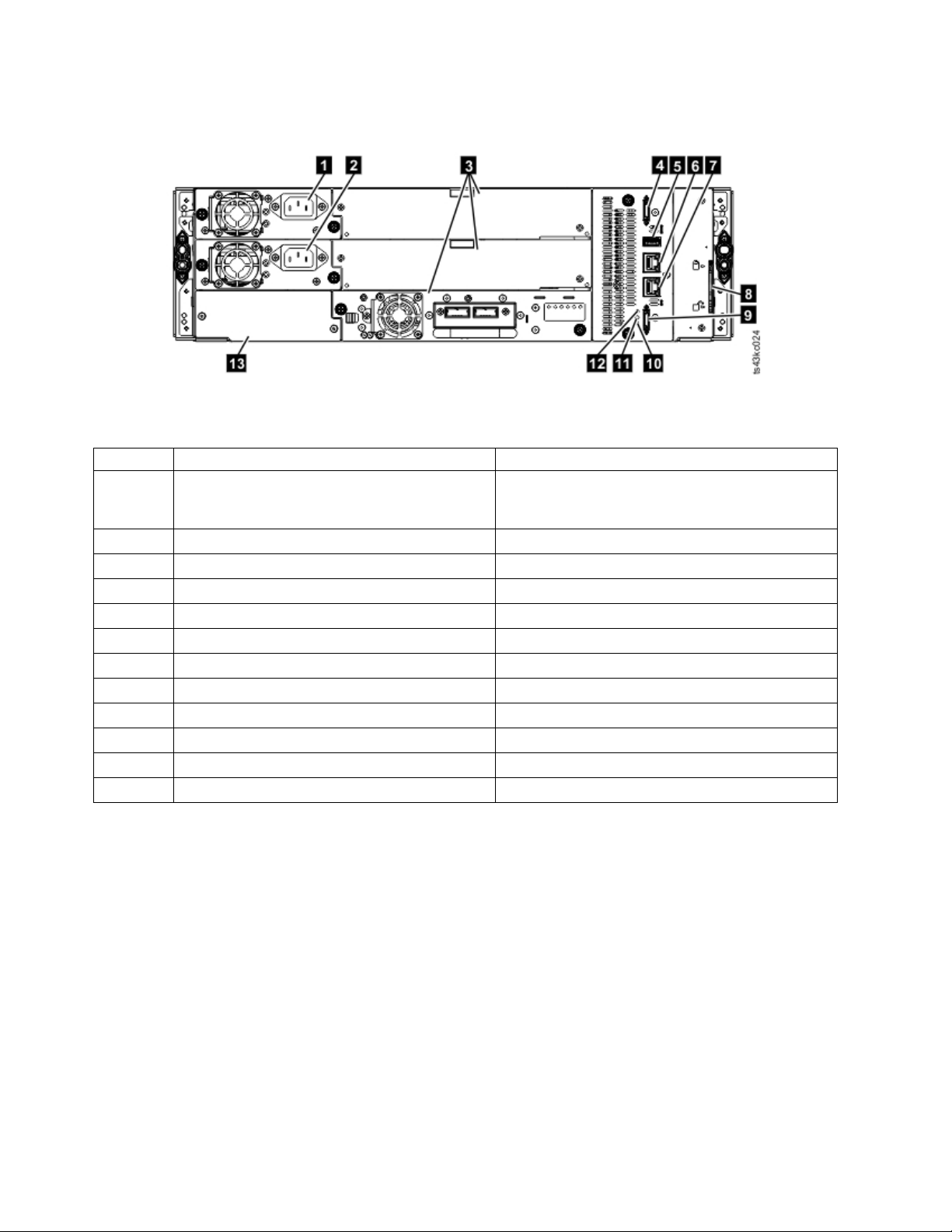
Rear panel
Figure 12. Rear panel
Table 7. Rear panel descriptions
Number Item Comments
▌1▐ Power supply 1 Standard on Base Module
Optional on Expansion Module (required
if drives are present)
▌2▐ Power supply 2 Optional on Base Module and Expansion Modules
▌3▐ Tape drive bays
▌4▐ Upper Expansion Module connection port
▌5▐ USB port Base Module only
▌6▐ Ethernet port B Base Module only (secondary port for service usage)
▌7▐ Ethernet port A Base Module only
▌8▐ Module alignment mechanism
▌9▐ Lower Expansion Module connection port
▌10▐ Unit Identifier LED, Blue
▌11▐ Controller Error LED, Yellow
▌13▐ Product Serial Number, Tag location
Physical and logical addresses of modules
The library assigns each module a unique address to indicate its physical location, shown in Figure 13 on
page 9. The physical numbering is bottom up on all modules.
8 Dell EMC ML3 Tape Library: User's Guide
Page 31
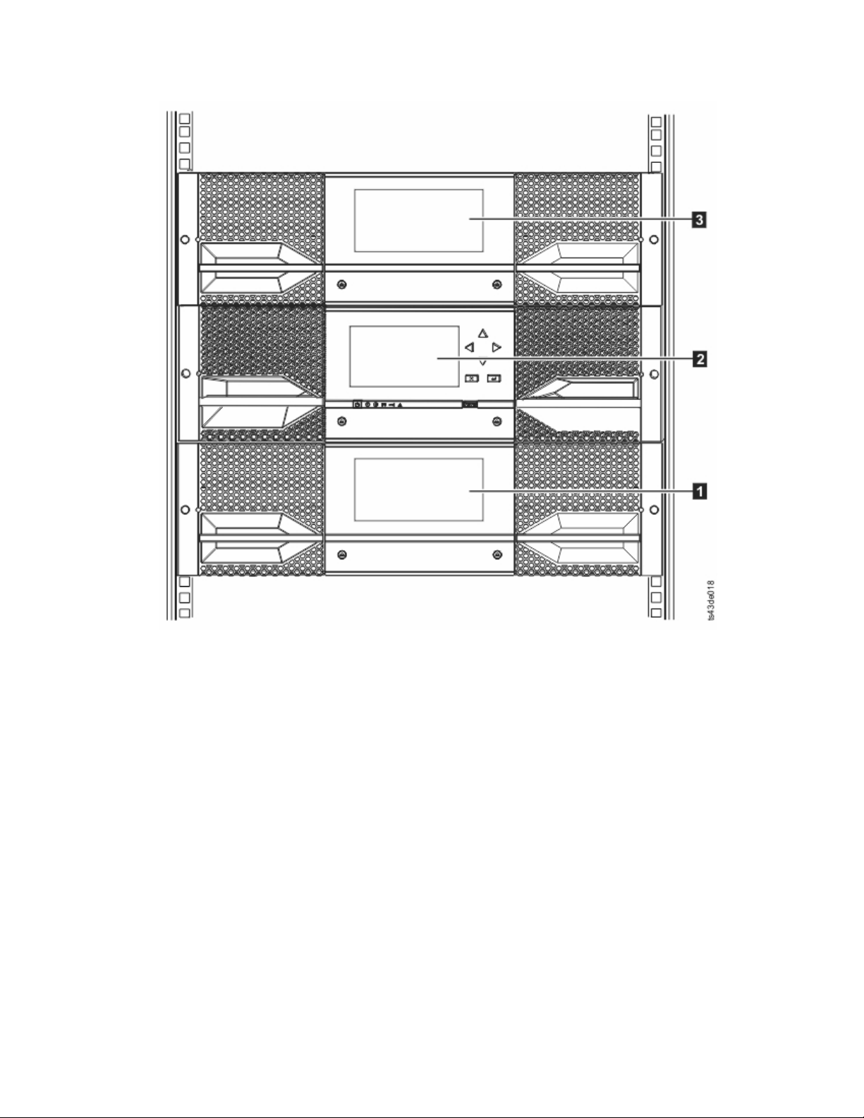
Figure 13. Physical numbering of modules
Magazines
Each module contains two magazines, holding up to 40 cartridges.
Overview 9
Page 32
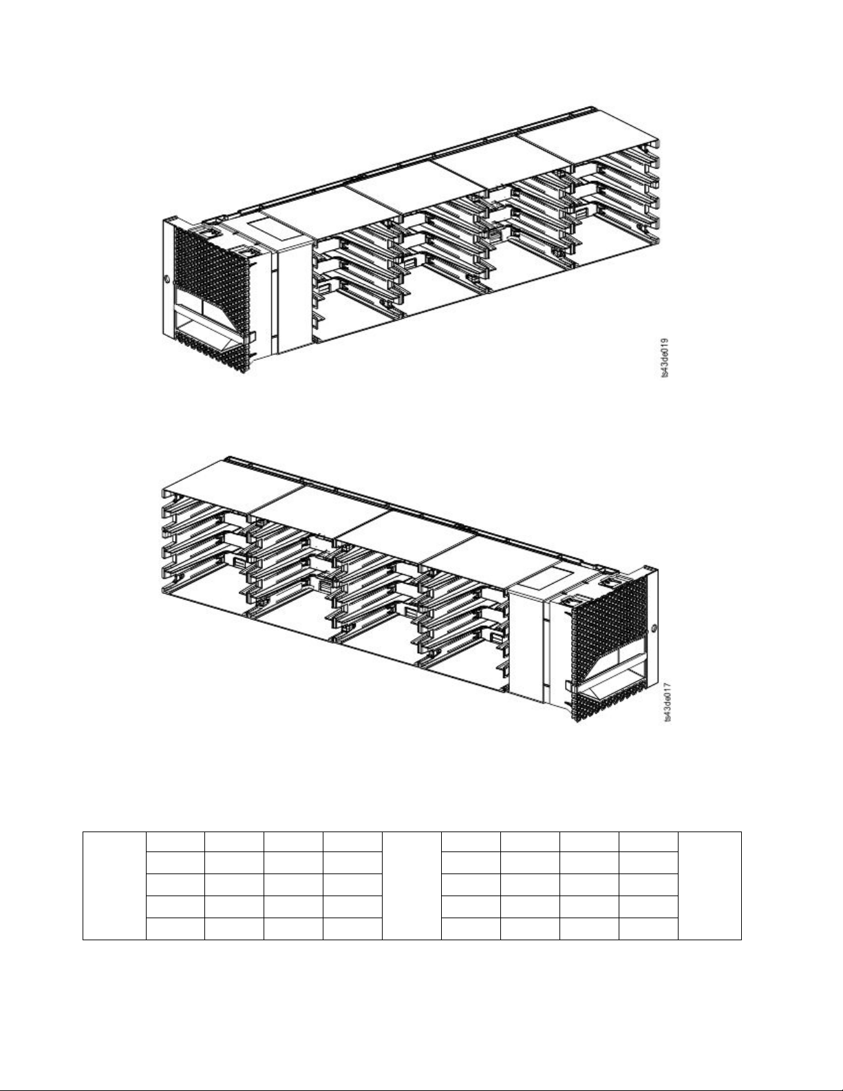
Figure 14. Left magazine
Figure 15. Right magazine
The library assigns each slot in a magazine a unique number to indicate its physical location. This
numbering is shown on the Cartridges page of the Management GUI.
Table 8. Physical numbering of storage slots - bottom module
Front of
the Left
Magazine
5 10 15 20
4 9 14 19 24 29 34 39
3 8 13 18 23 28 33 38
2 7 12 17 22 27 32 37
1 6 11 16 21 26 31 36
Drives
25 30 35 40
Front of
the Right
Magazine
Physical numbering of storage slots starts with the left magazine of the lowest module of your library. In
this module, the numbers of the lowest row (1, 6, 11, 16, 21, 26, 31, 36) are inaccessible to the accessor so
10 Dell EMC ML3 Tape Library: User's Guide
Page 33
that only 32 cartridges can be loaded. As modules are added above this module, the numbering
continues, starting with the lower left slot of the left magazine, and adding 40 storage slots for each
additional module.
Each module can be configured to contain an I/O Station, or one I/O Station can be accessed by several
modules. I/O Stations consist of five slots in the front column of the right magazine of each module,
except for the lowest module. The lowest module in a library can contain a 4-slot I/O Station only. To
enable or disable I/O Stations, go to Library > Modules and Magazines > Actions > Enable or Disable
I/O Station in the Management GUI.
Power supply
The library provides a single power supply with each library. However, a secondary redundant power
supply for the base module can be added. In addition, each expansion module with drives installed
requires a power supply.
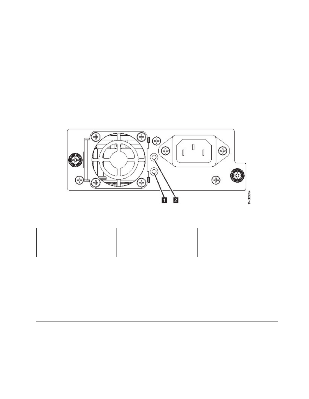
Figure 16. Power supply rear panel LEDs
Table 9. Power supply LEDs
Number Color Description
▌1▐ White AC power is connected, but Module
powered OFF
▌2▐ Green Module powered ON
Bar code reader
The high-speed bar code reader is a part of the Base Module. The bar code reader provides inventory
feedback to the host application, Operator Panel display, and Management GUI by reading cartridge bar
code labels. The library stores the customized inventory data in memory.
Library firmware supports a 6 or 8 character volume serial number (VOLSER) on the bar code label on
the tape cartridge. It is highly recommended to use bar code labeled cartridges. See “Labeling tape
cartridges” on page 145.
User interfaces
This library has two user interfaces.
v “The Management GUI” on page 59 - With the Management GUI, you can monitor, configure, and
control the library from a web browser. The Management GUI hosts a dedicated, protected Internet site
that displays a graphical representation of the library. For information on network connectivity, see
|
“Network connectivity” on page 20.
|
Overview 11
Page 34

v “The Operator Panel” on page 61 - With the Operator Panel, you can monitor, configure, and control
the library from the front panel. Functions are limited to those applicable to being in front of the
library.
Supported tape drives
The library supports LTO tape drives.
For minimum and maximum storage configurations, see Table 4 on page 2. For minimum firmware levels,
see “Minimum firmware levels for common library features” on page xi.
Listed are the tape drives that are implemented and qualified for use in this library.
Table 10. Supported tape drives
Form factor
Type
LTO6 1U (Half-height) Serial Attached
LTO6 1U (Half-height) Fibre Channel
LTO6 2U (Full-height) Fibre Channel
LTO7 1U (Half-height) Serial Attached
LTO7 1U (Half-height) Fibre Channel
LTO7 2U (Full-height) Fibre Channel
LTO8 1U (Half-height) Serial Attached
LTO8 1U (Half-height) Fibre Channel
LTO8 2U (Full-height) Fibre Channel
(height) Interface Number of Ports
SCSI (SAS)
(FC)
(FC)
SCSI (SAS)
(FC)
(FC)
SCSI (SAS)
(FC)
(FC)
2 6 Gbps SAS 160 MB/s
1 8 Gbps FC 160 MB/s
2 8 Gbps FC 160 MB/s
2 6 Gbps SAS 300 MB/s
1 8 Gbps FC 300 MB/s
2 8 Gbps FC 300 MB/s
2 6 Gbps SAS 300 MB/s
1 8 Gbps FC 300 MB/s
2 8 Gbps FC 360 MB/s
Speeds of
connectivity Native data rate
The LTO tape drives communicate with the library through an internal Ethernet interface. For enhanced
performance, the LTO tape drives include speed matching, channel calibration, and power management.
Speed matching dynamically adjusts the drive’s normal native (uncompressed) data rate to the slower
data rate of a server. Channel calibration customizes each read/write data channel for optimum
performance. The customization enables compensation for variations in the recording channel transfer
function, media characteristics, and read/write head characteristics. Power management reduces the
drive’s power consumption during idle power periods.
Control path drives
A control path is a logical path to the library. A control path is the path for SCSI Medium Changer
commands sent by a server to control a specific logical library. The library has no direct SCSI connection
to a host server. When a software host server communicates with the library, it sends the communication
by way of a tape drive. The tape drive is designated as a control path drive.
Mixed drives
All supported generations of LTO tape drives and cartridges can be in the same physical library and
within a single module.
12 Dell EMC ML3 Tape Library: User's Guide
Page 35
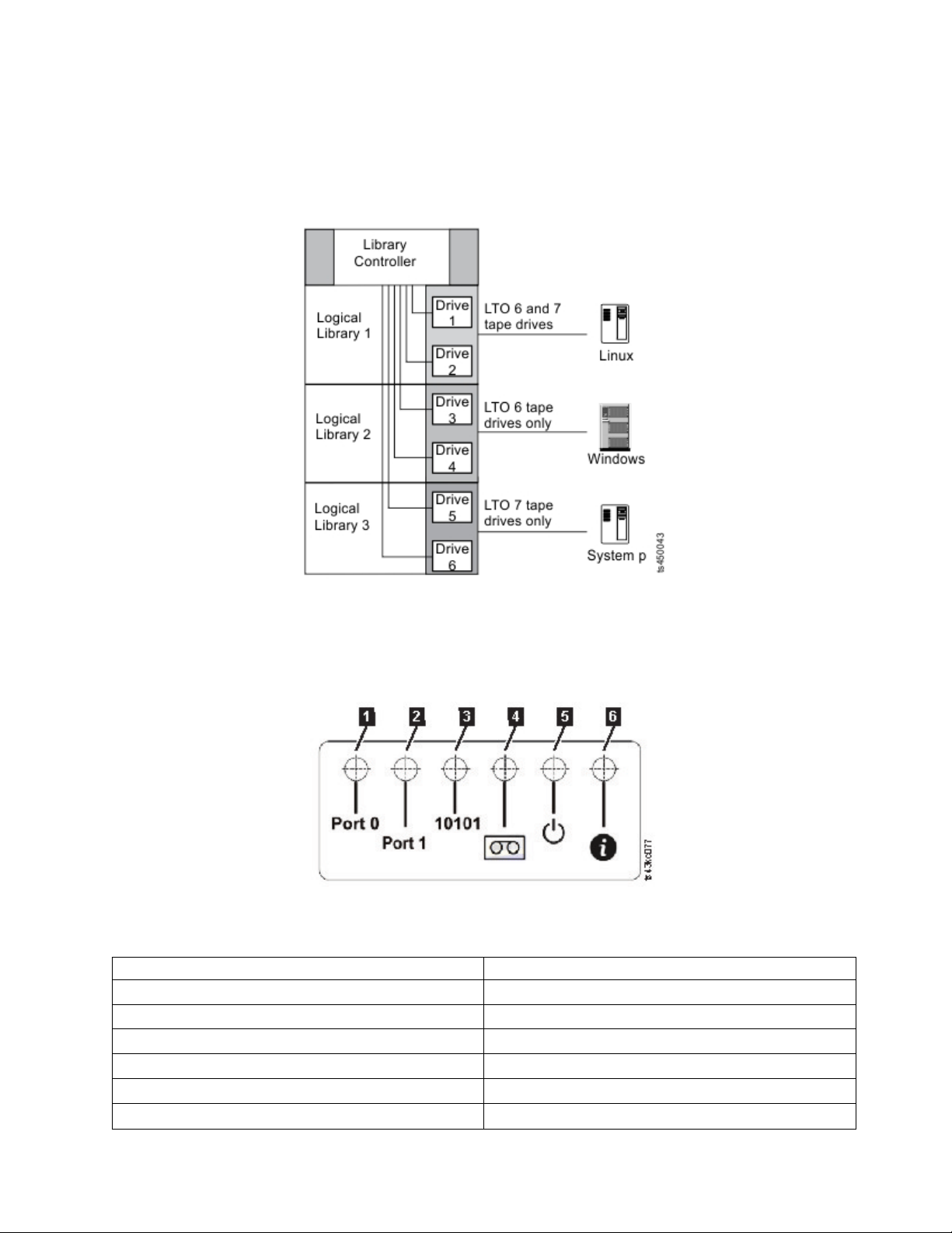
This library supports a mixture of LTO drive types in a logical library. Some independent software
vendors (ISVs) support mixed drive types within a logical library and other do not. Some ISVs that
support mixed drive types might have restrictions. For details, contact your ISV.
Figure 17 shows examples of methods for mixing LTO drive types in a logical library.
Figure 17. Mixed drives in a logical library
Drive sled back panels
Six indicator LEDs are included on all drive sleds as shown in Figure 18.
Figure 18. Drive sled indicators
Table 11. Drive sled indicators
Number Description
▌1▐ Port 0 activity
▌2▐ Port 1 activity
▌3▐ Library communication
▌4▐ Cartridge present
▌5▐ Power
▌6▐ Beacon /UID
Overview 13
Page 36
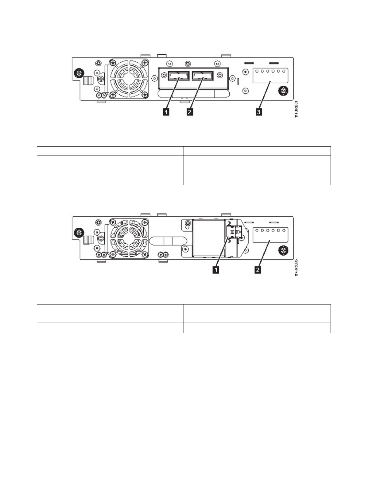
Figure 19. Half-height SAS dual port
Table 12. Half-height SAS dual port
Number Description
▌1▐ SAS port 0
▌2▐ SAS port 1
▌3▐ Drive sled indicators (see Figure 18 on page 13
Figure 20. Half-height FC single port
Table 13. Half-height FC single port
Number Description
▌1▐ FC port 0
▌2▐ Drive sled indicators (see Figure 18 on page 13
14 Dell EMC ML3 Tape Library: User's Guide
Page 37
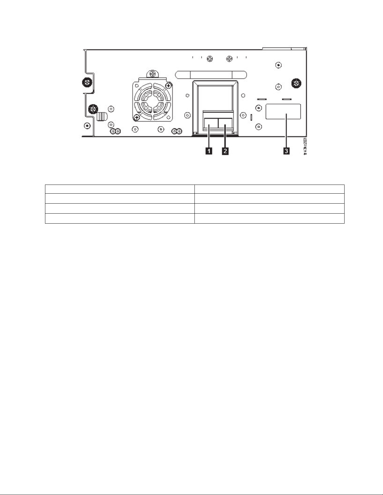
Figure 21. Full-height FC dual port
Table 14. Full-height FC dual port
Number Description
▌1▐ FC port 0
▌2▐ FC port 1
▌3▐ Drive sled indicators (see Figure 18 on page 13
Physical and logical addresses of drives
The library assigns each tape drive a unique address to indicate its physical location, shown in Figure 22
on page 16. The physical numbering is bottom up on all drives. This information is shown on the Drives
page of the Management GUI.
Overview 15
Page 38
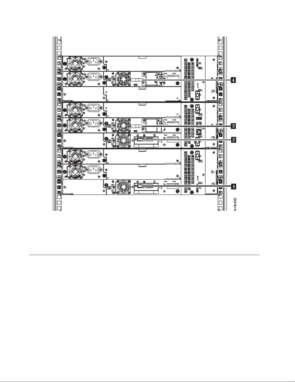
Figure 22. Physical numbering of drives
The library assigns each tape drive a SCSI element address that consists of a value that defines a logical
location in the library to the SCSI interface. It is assigned and used by the application when the host
server processes SCSI commands. The SCSI element address for a drive is unique to the location of the
drive. It does not vary based on other drives in the library. See “Library partitioning” on page 57.
Supported tape cartridges
Within the library, the supported LTO tape drives use the following cartridge types:
v LTO8 Data Cartridge
v LTO8 WORM Data Cartridge
v LTO7 Data Cartridge
v LTO7 WORM Data Cartridge
v LTO6 Data Cartridge
v LTO6 WORM Data Cartridge
v LTO5 Data Cartridge
v LTO5 WORM Data Cartridge
v LTO4 Data Cartridge
v LTO4 WORM Data Cartridge
v Universal LTO Cleaning Cartridge
16 Dell EMC ML3 Tape Library: User's Guide
Page 39

For information, see Appendix B, “LTO media,” on page 143.
Library functions
Encryption
All supported tape drives in this library support encryption.
The encryption enabled drive contains the necessary hardware and firmware to encrypt and decrypt host
tape application data. Encryption policy and encryption keys are provided by the host application or host
server. A drive digital certificate is installed at manufacturing time. Each drive receives a unique serial
number and certificate. The T10 application might validate each drive instance by checking the drive's
digital certificate.
The library provides these options.
1. Encryption disabled
2. Application Managed Encryption (AME)
3. Library Managed Encryption (KMIP) (LME). LME is a built-in feature. For configuration details, see
“Configuring Library Managed Encryption (KMIP)” on page 70.
The default is Application Managed Encryption.
Enabling library-managed encryption on a Dell EMC ML3 is a six-step process.
1. Upgrade the library and drive firmware to the current versions. The firmware can be found at
www.Dell.com/support.
2. Library-managed encryption on the library is already activated and cannot be deactivated.
If issues occur with the library-managed encryption on the library, go to http://www.dell.com/
tapeautomation for information on resolving the issue. If your issue is not resolved, contact Dell
technical support.
3. Configure library-managed encryption on your library.
4. Install the IBM SKLM application on the server that is designated as the key manager. See IBM SKLM
Knowledge Center for information.
5. Configure the IBM SKLM application. See IBM SKLM Knowledge Center for information.
6. Start the IBM SKLM application. See IBM SKLM Knowledge Center for information.
Note: All encryption settings must be configured or reverified in the drive after any library or drive
reset. A new drive might be added or an existing drive might be swapped with another drive.
Library sharing
The library can be configured into one or more logical libraries that can be shared by multiple
applications.
It is advantageous to be able to share a single physical library between heterogeneous or homogeneous
applications. However, some applications (and some servers) do not allow for sharing a library between
systems.
The library Management GUI provides two methods for logical library configuration.
1. A quick configuration for a simple one logical library configuration
2. An advanced configuration action for a multiple logical library configuration
Overview 17
Page 40

The second method gives the ability to create configurations that enable the library to process commands
from multiple heterogeneous applications (such as a Windows application) and multiple homogeneous
applications (for example, the same application run by several System p servers). See “Advanced library
configuration” on page 55.
Path failover and load balancing
The path failover feature ensures the use of a redundant communication path when the primary path
fails.
Command failures and time outs are costly. You want your library to run smoothly and efficiently. Path
failover capabilities allow the device driver to resend a command to an alternate path. The alternate path
can include another host bus adapter (HBA), Storage Area Network (SAN), or library control path drive.
The device driver initiates error recovery and continues the operation on the alternate path without
interrupting the application.
Path failover and load balancing are built-in features that are enabled by using a purchased license. The
path failover feature can be ordered from the factory, or you can order it as a field upgrade. The path
failover feature is activated on the Management GUI. To order features, contact your Sales Representative
or Business Partner.
Two types of path failover capabilities exist: control path failover (CPF) and data path failover (DPF). Control
refers to the command set that controls the library (the SCSI Medium Changer command set on LUN 1 of
the tape drives). Data refers to the command set that carries the customer data to and from the tape
drives (the SCSI-3 Stream Commands (SSC) device on LUN 0 of the tape drives). Path failover means the
same thing in both. Path failover is where redundancy is in the path from the application to the intended
target (the library accessor or the drive mechanism), the device driver transparently fails over to another
path in response to a break in the active path.
Both types of failover include host-side failover when configured with multiple HBA ports into a switch.
But CPF includes target-side failover through the control paths that are enabled on more than one tape
drive. DPF includes target-side failover for the dual-ported tape drives that are supported by the library.
DPF includes load balancing of the HBAs because the channel is a data-intensive path (the control path
carries little data, so load balancing is not an issue). The dynamic load balancing support optimizes
resources for devices that have physical connections to multiple HBAs in the same machine. When an
application opens a device where multiple HBA paths are configured, the device driver determines which
path has the HBA with the lowest usage and assigns that path to the application. When another
application opens a different device with multiple HBA paths, the device driver again determines the
path with the lowest HBA usage and assigns that path to the second application. The device driver
updates the usage on the HBA assigned to the application when the device is closed. Dynamic load
balancing uses all HBAs whenever possible and balances the load between them to optimize the
resources in the machine.
Both CPF and DPF require the use of the current device driver. They are supported exclusively with
products that bear the Dell logo on the operating systems that is indicated in Table 15.
Table 15 summarizes the differences between CPF, DPF, and load balancing.
Table 15. Differences between CPF and DPF
Characteristic CPF DPF and Load Balancing
Device type SMC
3
LUN
Host-side failover Yes Yes
Target-side failover Yes
1
LUN 1 LUN 0
6
SSC
Yes
2
6
6
18 Dell EMC ML3 Tape Library: User's Guide
Page 41
Table 15. Differences between CPF and DPF (continued)
Characteristic CPF DPF and Load Balancing
Device driver required Yes Yes
Supported operating systems
Order feature to obtain license Yes Yes
Notes:
1. SMC = SCSI-3 Medium Changer Specification (library)
2. SSC = SCSI-3 Stream Commands (drive)
3. LUN = logical unit number
4. See “Host connectivity” on page 20 for details.
5. Load balancing is not supported on Windows
6. Full-height tape drives only
4
AIX®, SuSE Linux, Red Hat
Enterprise Linux, Solaris, Windows
AIX, SuSE Linux, Red Hat Enterprise
Linux, Solaris, Windows5(DPF only)
Alerts and logging
The library sends alerts about the library and attached tape drives, and offers audit-logging to track user
actions.
v TapeAlert Support: The tape library is compatible with TapeAlert technology, which provides error
and diagnostic information about the drives and the library to the host application. The library
provides this error and diagnostic information as TapeAlert flags that are reported to the application by
the SCSI LOG SENSE command. See “TapeAlert flags” on page 95.
v Email (SMTP - Simple Mail Transfer Protocol) Notifications: The library can configure email
notification of library events. The library must have network access to an SMTP server. See “Locating
Management functions” on page 63.
v Remote Logging (rsyslog): The library can send syslog (system log) notifications to a configured
remote (rsyslog) server. When system events occur, the ML3 tape library creates a log of these events.
With this notification feature configured, the library sends a notification of the event to the syslog
server. The syslog server keeps its own log of system events. (The syslog server is a customer-provided
server.) See “Locating Management functions” on page 63.
v SNMP Support: The Simple Network Management Protocol (SNMP) allows the library to send alerts
over a LAN network to a monitoring server.
Occasionally, the library might encounter situations that you want to know about. These situations can
be conditions that affect the library performance, such as an open door that causes the library to stop.
You might also want to log user actions, such as a cartridge move or export that is initiated from the
Management GUI. SNMP messages can alert you of these conditions.
The library provides a standard TCP/IP protocol that is called SNMP to send alerts about conditions
over a TCP/IP LAN network to an SNMP monitoring server. These alerts are called SNMP traps.
Using the information that is supplied in each SNMP trap, the monitoring server (together with
customer-supplied software) can alert operations staff of possible problems or operator interventions
that occur. Many monitoring servers can be used to send email or pager notifications when they
receive an SNMP alert. See the manual for your network management application.
The monitoring server must be loaded with systems management software that can receive and process
the trap. SNMP supports a get and get-response mechanism for an operator to gather more information
about a problem or query the library about its status. Through a monitoring server, the operator enters
a "get" using SNMP to request information about the library. A get-response is the information that is
provided in response to the get. This type of support generally requires an up-to-date library
Management Information Base (MIB). The SNMP server's MIB contains units of information that
specifically describe an aspect of a system, such as the system name, hardware number, or
communications configuration.
SNMP Notification Levels
Overview 19
Page 42

SNMP provides various levels of notification about specific library events and user actions.
– Inactive – No events are sent.
– Critical – Only critical events are sent.
– + Warnings – Only critical and warning events are sent.
– + Configuration – Only critical, warning, and configuration events are sent.
– + Information – All events are sent.
Simple Network Management Protocol (SNMP) audit logging provides logging information about
specific tape library user actions. To configure SNMP, see “Locating Management functions” on page
63.
Host connectivity
Compatible servers and software
The library is supported by a wide variety of servers, operating systems, and adapters. There are many
ways to determine the servers and software that support this library.
These attachments can change throughout the lifecycle of the product. To determine the newest
attachments, or to get a comprehensive list of compatible software, do one of the following actions.
v For a list of compatible software, operating systems, and servers for LTO tape drives, see
www.Dell.com/support.
Notes:
1. Dell does not provide application software with this library. To order software, contact your sales
representative, Business Partner, or an independent software provider.
2. If you attach your library to a server with non-Dell software, contact your software vendor for a
matrix of compatible hardware, software, firmware revisions, and adapter cards.
Note: The library requires an HBA with multiple LUN supports. Also, multiple LUN supports must be
enabled on the host computer. When multiple LUN supports are not enabled, the host computer can see
the tape drive, but not the library.
Supported device drivers
Dell provides device driver support for the LTO tape drives, and the robotics in this library.
Dell maintains the current levels of device drivers and driver documentation on the web. Go to
www.Dell.com/support and follow the steps to access this material.
Network connectivity
Supported browsers
|
IBM supports higher versions of the browsers if the vendors do not remove or disable functions that the
|
product relies upon. For browser levels higher than the versions that are certified with the product,
|
customer support accepts usage-related and defect-related service requests. As with operating system and
|
virtualization environments, if IBM support cannot re-create the issue in the lab, the client might be asked
|
to re-create the problem on a certified browser version to determine whether a product defect exists.
|
Defects are not accepted for cosmetic differences between browsers or browser versions that do not affect
|
the functional behavior of the product. If a problem is identified in the product, defects are accepted. If a
|
problem is identified with the browser, IBM might investigate potential solutions or workarounds that the
|
client can implement until a permanent solution becomes available.
|
20 Dell EMC ML3 Tape Library: User's Guide
Page 43

Supported interfaces
This tape library supports the Gigabit Ethernet interface in either auto negotiation or fixed modes of 10
Mbps, 100 Mbps, and 1 Gbps by using half or full duplex. The library supports the following TCP/IP
protocols:
IPv4 and IPv6 support
This tape library supports Internet Protocol (IP) addresses in both IPv4 and IPv6 format. Both the
integrated management console (IMC) and the management GUI allow the definition of IPv4 and
IPv6 addresses. The key proxy determines the IP version that is used and presents the correct IP
address and parameters to the IP Stack.
Simple Network Management Protocol (SNMP)
SNMP traps are supported for drive and library events. SNMP management query functions are
supported by using a standard Management Information Block (MIB).
Hyper Text Transfer Protocol (HTTP)
An embedded web server provides a management GUI for library management and query
capabilities.
Secure Socket Layer (SSL)
The tape library supports SSL, a protocol for transmitting private documents through the internet.
Key Management Interoperability Protocol (KMIP)
Used for communicating with the IBM®Security Lifecycle Key Manager and other security key
management software.
Simple Mail Transfer Protocol (SMTP)
The tape library supports SMTP for sending email alerts.
Network Time Protocol (NTP)
The tape library supports NTP for external time-and-date synchronization.
Lightweight Directory Access Protocol (LDAP)
The tape library supports LDAP for centralized authentication.
Domain Name System (DNS)
The tape library supports DNS for flexible IP addressing.
Dynamic Host Configuration Protocol (DHCP)
The library supports DHCP for automatically providing an Internet Protocol (IP) host with its IP
address and other related configuration information, such as the subnet mask and default
gateway.
Overview 21
Page 44

22 Dell EMC ML3 Tape Library: User's Guide
Page 45

Planning
The library requires an environment able to accommodate the appropriate space, power, location, and
other technical specifications. Use this section as a reference for onsite requirements to allow for optimum
operation of the library. Save your settings in the Appendix A, “Library Configuration Forms,” on page
137.
Library Layout and Location requirements
For tabletop installation - Tabletop installations (one Base Module) require no additional hardware.
For rackmount installation - If possible, install the Base Module in the middle of the rack to provide
space for the allowed three Expansion Modules above it and three Expansion Modules below it. See
“Structure and supported library configurations” on page 2 for details.
Security
The equipment must be located so that access to the equipment can be controlled and monitored.
Consider all of these recommended security measures when you are determining where to locate your
tape library.
Library location
You are responsible for the security of this library, the cartridges that are contained within the
library, and shelf-resident cartridges. To prevent unauthorized access to data, Dell recommends
locating the library and all shelf-resident cartridges in an area where access is controlled.
Onsite security measures
You are also responsible for evaluating, selecting, and implementing security features,
administrative procedures, and appropriate controls in application systems and communication
facilities.
Data security
Data security is accomplished through the Management GUI. See “Locating Management
functions” on page 63.
Location requirements
Choose a location that meets the criteria in Table 16.
Table 16. Location requirements
Criteria Definition
Rack requirements Standard 19-inch rack (minimum depth of 1 meter) with an appropriate # of Us
(Rack Units) of clearance for the planned module quantity (See Table 17 on page
24 for details.)
Rack space requirements 3U for the Base Module and 3U for each Expansion Module
Power source
v AC Power Voltage: 100 - 240 VAC
v Line Frequency: 50 - 60 Hz
v Library is located near AC outlet.
The AC power cord must be always easily accessible.
23
Page 46
Table 16. Location requirements (continued)
Criteria Definition
Air quality
v Place the library in an area with minimal sources of particulate contamination.
v Avoid areas near frequently used doors and walkways, stacks of supplies that
collect dust, printers, and smoke-filled rooms.
v Excessive dust and debris can damage tapes and tape drive.
Technical specifications for this library can be referenced in the following tables.
Physical specifications
Table 17. Physical specifications
Characteristic Product alone Packaged
Height 133 mm 694 mm
Width 480 mm
|
Depth 873 mm 1194 mm
Weight Base module: 21 Kg
Expansion module: 13 Kg
1
Includes front covering of rack rails, allowing for magazine opening clearance.
|
1
667 mm
Base module: 30 Kg
Expansion module: 23 Kg
Electrical specifications
Table 18. Electrical specifications
Characteristic Specification
Current 5.0 - 3.5 A
Voltage 100 - 240 V 50/60 Hz
Power 350 W
Equipment environmental specifications
Table 19. Equipment environmental specifications
ML3 Operating environment Product power off
Dry bulb
temperature
(deg C)
Allowable Recom-
mended
15 to 32 16 to 25 20 to 80 20 to 50
Notes:
v Derate maximum dry-bulb temperature 1°C/300 in (34°F/984 ft.) above 900 m (2,953 ft.).
v Derate maximum recommended dry-bulb temperature 1°C/300 in (34°F/984 ft.) above 1,800 m (5,905 ft.).
Relative Humidity
(%RH, noncondensing)
Allowable Recom-
mended
Max wet
bulb
temperature
(deg C)
26 3050 5 to 45 8 to 80 26
Max
elevation
(meters)
Dry bulb
temperature
(deg C)
Relative
Humidity
(%RH,
noncondensing)
Max wet
bulb
temperature
(deg C)
24 Dell EMC ML3 Tape Library: User's Guide
Page 47
Gas and particulate exposure
Table 20. Gas and particulate exposure
Contamination Requirement
Gaseous contamination Severity level G1 as per ANSI/ISA 71.04-19851, which states that the reactivity rate of
copper coupons shall be less than 300 Angstroms per month (Å/month, ≈ 0.0039
µg/cm² - hour weight gain)2. In addition, the reactivity rate of silver coupons shall be
less than 300 Å/month (≈ 0.0035 µg/cm² - hour weight gain)3. The reactive monitoring
of gaseous corrosivity should be conducted approximately 5 cm (2 in.) in front of the
rack on the air inlet side at one-quarter and three-quarter frame height off the floor or
where the air velocity is much higher.
Particulate contamination Data centers must meet the cleanliness level of ISO 14644-1 class 8. For data centers
without airside economizer, the ISO 14644-1 class 8 cleanliness might be met by the
choice of the following filtration:
v The room air might be continuously filtered with MERV 8 filters.
v Air entering a data center might be filtered with MERV 11 or preferably MERV 13
filters.
For data centers with airside economizers, the choice of filters to achieve ISO class 8
cleanliness depends on the specific conditions present at that data center. The
deliquescent relative humidity of the particulate contamination should be more than
60% RH.34.Data centers must be free of zinc whiskers5.
Notes:
1. ANSI/ISA-S71.04. 1985. Environmental conditions for process measurement and control systems: Airborne contaminants,
Instrument Society of America, Research Triangle Park, NC, 1985.
2. The derivation of the equivalence between the rate of copper corrosion product thickness growth in Å/month
and the rate of weight gain assumes that Cu2S and Cu2O grow in equal proportions.
3. The derivation of the equivalence between the rate of silver corrosion product thickness growth in Å/month and
the rate of weight gain assumes that Ag2S is the only corrosion product.
4. The deliquescent relative humidity of particulate contamination is the relative humidity at which the dust
absorbs enough water to become wet and promote ionic conduction.
5. Surface debris is randomly collected from 10 areas of the data center on a 1.5 cm diameter disk of sticky
electrically conductive tape on a metal stub. If examination of the sticky tape in a scanning electron microscope
reveals no zinc whiskers, the data center is considered free of zinc whiskers.
Power cords
To avoid electrical shock, a power cord with a grounded attachment plug is provided. Use
only properly grounded outlets.
Table 21 on page 26 lists the power cord part number, feature code, the country, or region
where the power cord is used, and the plug's standard reference. The last column in the
table contains an index number that you can match to a specific receptacle type in Figure 23
on page 30.
All power cords use an appliance coupler that complies with the International
Electrotechnical Commission (IEC) Standard 320, Sheet C13.
If the power cord that you receive does not match your receptacle, contact your local dealer.
Power cords that are used in the United States and Canada are listed by Underwriter's
Laboratories (UL), are certified by the Canadian Standards Association (CSA), and comply
with the plug standards of the National Electrical Manufacturers Association (NEMA). For
other worldwide geographies, plug standards are listed in Table 21 on page 26.
Planning 25
Page 48

Table 21. Power cords
Description, Feature Code
(FC), and Part Number
(P/N)
US/Canada
v 2.8 m, 125 V
v FC 9800
v P/N 95P2344
Chicago
v 1.8 m, 125 V
v FC 9986
v P/N 39M5080
US/Canada
v 2.8 m, 250 V
v FC 9833
v P/N 95P2353
Australia
v 2.8 m, 250 V
v FC 9831
v P/N 95P2352
Plug Standard
Reference
NEMA 5-15P Aruba, Bahamas, Barbados,
NEMA 5-15P Chicago, U.S.A. 1
NEMA 6-15P Aruba, Bahamas, Barbados,
AS 3112
NZS 198
Country or Region Index Number in Figure 23
on page 30
Bermuda, Bolivia, Brazil,
Canada, Cayman Islands,
Colombia, Costa Rica,
Curacao, Dominican
Republic, Ecuador, El
Salvador, Guatemala, Guyana,
Haiti, Honduras, Jamaica,
Japan, Liberia, Mexico,
Netherlands Antilles,
Nicaragua, Panama, Peru,
Philippines, Saudi Arabia,
South Korea, Suriname,
Taiwan, Trinidad Tobago,
Venezuela, US
Bermuda, Bolivia, Brazil,
Canada, Cayman Islands,
Costa Rica, Curacao,
Dominican Republic, Ecuador,
El Salvador, Guatemala,
Guyana, Haiti, Honduras,
Jamaica, Japan, Liberia,
Netherlands Antilles,
Nicaragua, Panama, Peru,
Philippines, Suriname,
Taiwan, Thailand, Trinidad
Tobago, Venezuela, US
Australia, China, Colombia,
New Zealand, Papua New
Guinea, Paraguay, Uruguay,
Western Samoa
1
2
3
26 Dell EMC ML3 Tape Library: User's Guide
Page 49

Table 21. Power cords (continued)
Description, Feature Code
(FC), and Part Number
(P/N)
France, Germany
v 2.8 m, 250 V
v FC 9820
v P/N 95P2345
Denmark
v 2.8 m, 250 V
v FC 9821
v P/N 95P2346
South Africa
v 2.8 m, 250 V
v FC 9829
v P/N 95P2350
United Kingdom
v 2.8 m, 250 V
v FC 9825
v P/N 95P2347
Plug Standard
Country or Region Index Number in Figure 23
Reference
CEE 7 - VII Afghanistan, Algeria,
Andorra, Angola, Aruba,
Austria, Belgium, Benin,
Brazil, Bulgaria, Burkina
Faso, Burundi, Cameroon,
Central African Republic,
Chad, Congo-Brazzaville,
Curacao, Czech Republic,
Democractic Republic of
Congo, Denmark, Egypt,
Finland, France, French
Guiana, Germany, Greece,
Guinea, Hungary, Iceland,
Indonesia, Iran, Ivory Coast,
Jordan, Kenya, Korea,
Lebanon, Luxembourg,
Macau, Malagasy, Mali,
Martinique, Mauritania,
Mauritius, Monaco, Morocco,
Mozambique, Netherlands,
Netherlands Antilles, New
Caledonia, Niger, Norway,
Poland, Portugal, Romania,
Russia, Saudi Arabia, Senegal,
Spain, Sweden, Sudan, Syria,
Togo, Tunisia, Turkey,
Yugoslavia, Zaire, Zimbabwe,
Vietnam
DK2-5A Denmark 5
SABS 164 Bangladesh, Burma, Pakistan,
South Africa, Sri Lanka
BS 1363 Antigua, Bahrain, Bermuda,
Brunei, Channel Islands,
China (Hong Kong S.A.R.),
Cyprus, Fiji, Ghana, Guyana,
India, Iraq, Ireland, Jordan,
Kenya, Kuwait, Malaysia,
Malawi, Malta, Nepal,
Nigeria, Oman, Polynesia,
Qatar, Sierra Leone,
Singapore, Tanzania, Uganda,
UK, United Arab Emirate
(Dubai), Yemen, Zambia
on page 30
4
6
7
Planning 27
Page 50

Table 21. Power cords (continued)
Description, Feature Code
(FC), and Part Number
(P/N)
Switzerland
v 2.8 m, 250 V
v FC 9828
v P/N 95P2349
Italy
v 2.8 m, 250 V
v FC 9830
v P/N 95P2351
Israel
v 2.8 m, 250 V
v FC 9827
v P/N 95P2348
Argentina
v 2.8 m, 250 V
v FC 9834
v P/N 95P2354
China
v 2.8 m, 250 V
v FC 9840
v P/N 95P2355
Taiwan LV*
v 2.8 m, 125 V
v FC 9835
v P/N 23R3263
Taiwan HV**
v 2.8 m, 250 V
v FC 9841
v P/N 23R6120
Japan LV*
v 2.8 m, 125 V
v FC 9842
v P/N 23R6121
Japan HV**
v 2.8 m, 250 V
v FC 9843
v P/N 39M5186
Korea HV**
v 2.8 m, 250 V
v FC 9844
v P/N 23R6123
KS C8305, K60884-1 Korea 17
Plug Standard
Reference
SEV S/N 416534 Liechtenstein, Switzerland 8
CEI 23- 16 Chile, Ethiopia, Italy, Libya,
S11-32-1971 Israel 10
IEC 83-A5 Argentina, Brazil, Colombia,
CCEE People's Republic of China 12
CNS 10917-3 Taiwan 13
CNS 10917-3 Taiwan 14
JIS C8303, C8306 Japan 15
JIS C8303, C8306 Japan 16
Country or Region Index Number in Figure 23
on page 30
Somalia
11
Paraguay, Trinidad Tobago,
Uruguay
9
28 Dell EMC ML3 Tape Library: User's Guide
Page 51

Table 21. Power cords (continued)
Description, Feature Code
(FC), and Part Number
(P/N)
India HV**
v 2.8 m, 250 V
v FC 9845
v P/N 23R6124
Brazil LV*
v 2.8 m, 125 V
v FC 9846
v P/N 39M5233
Brazil HV**
v 2.8 m, 250 V
v FC 9847
v P/N 23R6126
Rack PDU
v FC 9848
v P/N 23R6328
* Low Voltage
InMetro NBR 6147 Brazil 19
InMetro NBR 14136 Brazil 20
Plug Standard
Reference
IS 6538 India 18
Country or Region Index Number in Figure 23
on page 30
** High Voltage
Figure 23 on page 30 shows the plugs that are used by the power cords in Table 21 on page 26. Match the
index number that is beside each plug to the index number in the table.
Planning 29
Page 52
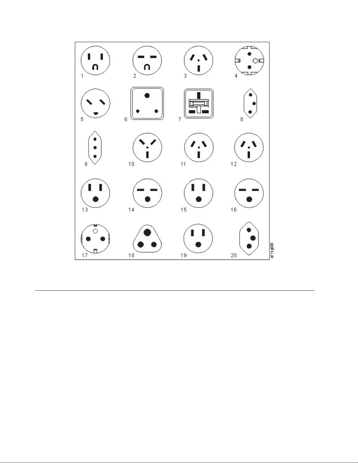
Figure 23. Types of receptacles
Network requirements
The library supports an independent customer network. It is the customer’s responsibility to provide the
proper length Ethernet cable for this connectivity.
The base module controller card has two Ethernet ports, which offer primary and redundant customer
network connectivity. See “Rear panel” on page 8.
These connections allow remote viewing and management of the library with the Management GUI.
Note: Have your network settings handy to use for entering on the Operator Panel. Your network
settings can also be stored as hardcopy on Appendix A, “Library Configuration Forms,” on page 137.
The secondary Ethernet port might be used for service. Three models are available for connection:
v No Ethernet port - Service personnel can connect a laptop to the customer network to use the
Management GUI with service login.
v Dedicated secondary Ethernet port - The secondary network port that is dedicated only for service
personnel to connect a laptop directly to the library.
30 Dell EMC ML3 Tape Library: User's Guide
Page 53
v Secondary Ethernet port - The secondary network port can be disconnected and service personnel can
use it to connect a laptop directly to the library.
IP range selection
For internal communication between modules, the tape library uses an Ethernet connection with an
internal IP address range. To prevent any conflict between the internal IP address range and the external
IP addresses, you must select the internal IP range. Choosing the Internal IP address range, and also
entering the external IP address information is part of the initial setup of the library.
Host requirements
The library requires attachment to supported SAS or FC HBAs. See “Host connectivity” on page 20.
Static Sensitive
Risk of damage to devices
v A discharge of static electricity damages static-sensitive devices or
micro circuitry.
v Proper packaging and grounding techniques are necessary
precautions to prevent damage.
Follow these general guidelines.
v Check with a system administrator before the host computer is powered off.
v For a SAS library, confirm availability or install a SAS HBA that supports multiple LUNs.
v For a direct-attach Fibre Channel library, confirm availability of installation of an FC HBA.
v For connection of a Fibre Channel library through a compatible switch, verify that sufficient ports are
available.
Persistent binding to ensure SCSI ID assignment
When a server is booted, devices are discovered and assigned SCSI target and LUN IDs. It is possible for
these SCSI assignments to change between boots. Some operating systems do not guarantee that devices
are always allocated the same SCSI target ID after rebooting. Also, some software depends on this
association, so you do not want it to change. The issue of SCSI ID assignment is addressed by persistent
binding.
Persistent binding is an HBA function that allows a subset of discovered targets to be bound between a
server and device. Implemented by a worldwide node name (WWNN) or worldwide port name
(WWPN), persistent binding causes a tape drive's WWNN to be bound to a specific SCSI target ID. After
a configuration is set, it survives restarts and any hardware configuration changes because the
information is preserved. If a drive must be replaced, the new drive assumes the WWNN of the old drive
because the WWNN for the drive is location-dependent within the library. Because the WWNN does not
change, persistent binding does not need changing, thus preventing a potential outage.
Planning 31
Page 54

32 Dell EMC ML3 Tape Library: User's Guide
Page 55
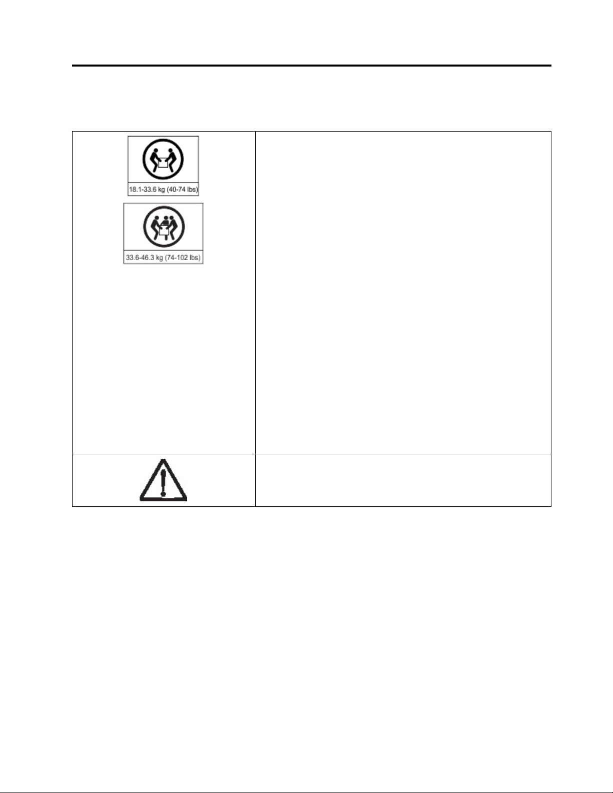
Installing
Table 22. Installation Precautions
Product Weight
Caution: The weight of this part or unit is between 18.1 and 33.6 kg
(40 and 74 lb). It takes two persons to safely lift this part or unit.
(C009)
Caution: The weight of this part or unit is between 33.6 and 46.3 kg
(74 and 102 lb). It takes three persons to safely lift this part or unit.
(C010)
Risk of personal injury
Before a module is lifted or moved
v Observe local health and safety requirements and guidelines for
manual material handling.
v Remove all tapes to reduce the weight and to prevent cartridges
from falling into the robotics path and damaging the library.
v Remove all tape drives to reduce the weight.
v Obtain adequate assistance to lift and stabilize the module during
installation or removal.
Risk of damage to devices
When a module is placed into or the module is removed from a rack
v Extend the rack’s leveling jacks to the floor.
v Ensure that the full weight of the rack rests on the leveling jacks.
v Install stabilizing feet on the rack.
v Extend only one rack component at a time.
v Do not expose the library to moisture.
v Do not place a module on either the ends or sides as this action
might cause damage
Complete these procedures to install your library hardware.
1. “Unpacking the Base Module and Expansion Modules” on page 34
2. “Identifying Library Module components” on page 39.
3. “Preparing top and bottom modules” on page 39.
4. “Installing modules in a rack” on page 42.
5. “Installing a tabletop module” on page 46.
6. “Aligning and connecting modules” on page 46
7. “Validating tape drive installation” on page 49.
8. “Connecting cables” on page 49.
9. “Powering on the library” on page 51
Complete these procedures to configure your library.
1. “The Initial Setup process” on page 52
2. “Initial configuration and customization” on page 53
33
Page 56
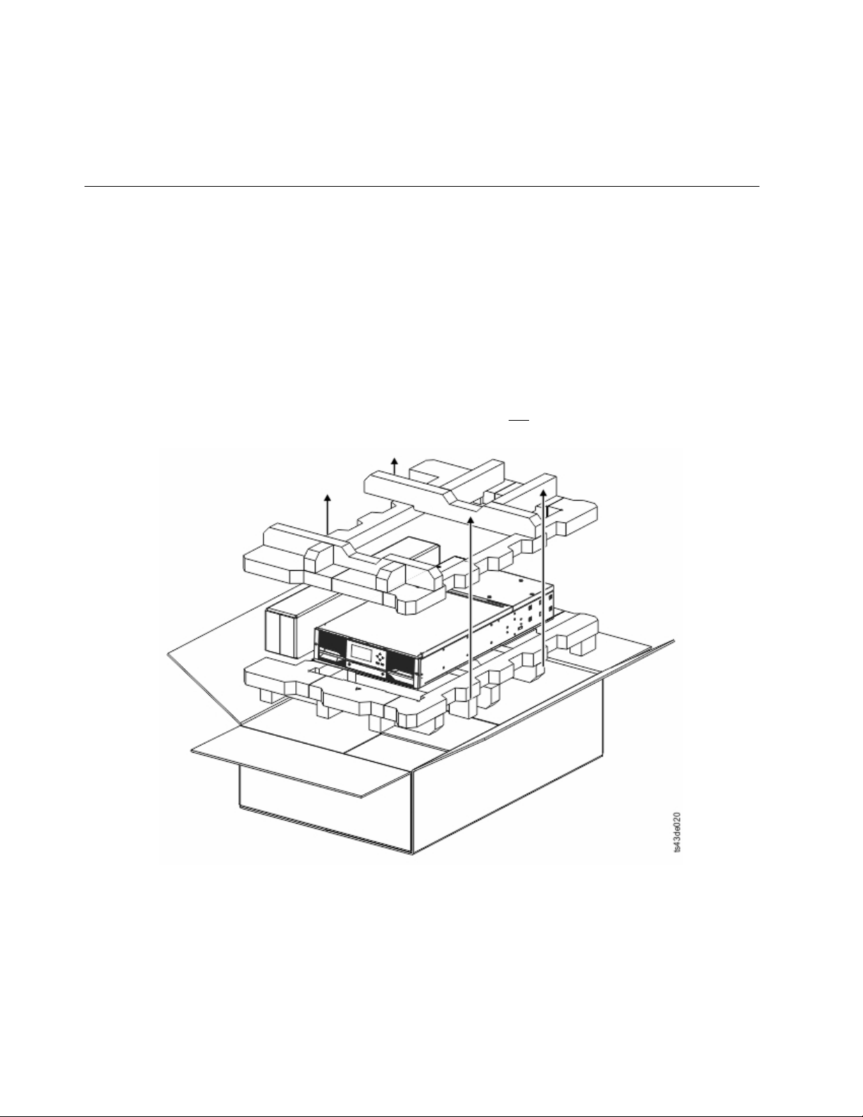
3. “Labeling and loading tape cartridges” on page 53
4. “Verifying the installation” on page 55
5. “Advanced library configuration” on page 55
6. “Verifying the host connection” on page 58
Unpacking the Base Module and Expansion Modules
Before any modules are unpacked, clear a work surface near the targeted rack or table for installation.
Attention: If the temperature in the room where the library operates varies by 15° C (30° F) from where
the module was stored, allow it to acclimate for at least 12 hours before it is unpacked.
Unpacking a Base Module or Expansion Module
1. Before a module is opened or removed from the box, inspect the container for shipping damage.
2. If you notice any damage, report it to the shipping company immediately.
3. Remove the module from the box.
Important: Lift the module out of the box by the long sides, not by the display.
Figure 24. Removing the module from the box
4. Check that all components for assembling the module are in the box. See “Identifying Library
Module components” on page 39.
34 Dell EMC ML3 Tape Library: User's Guide
Page 57
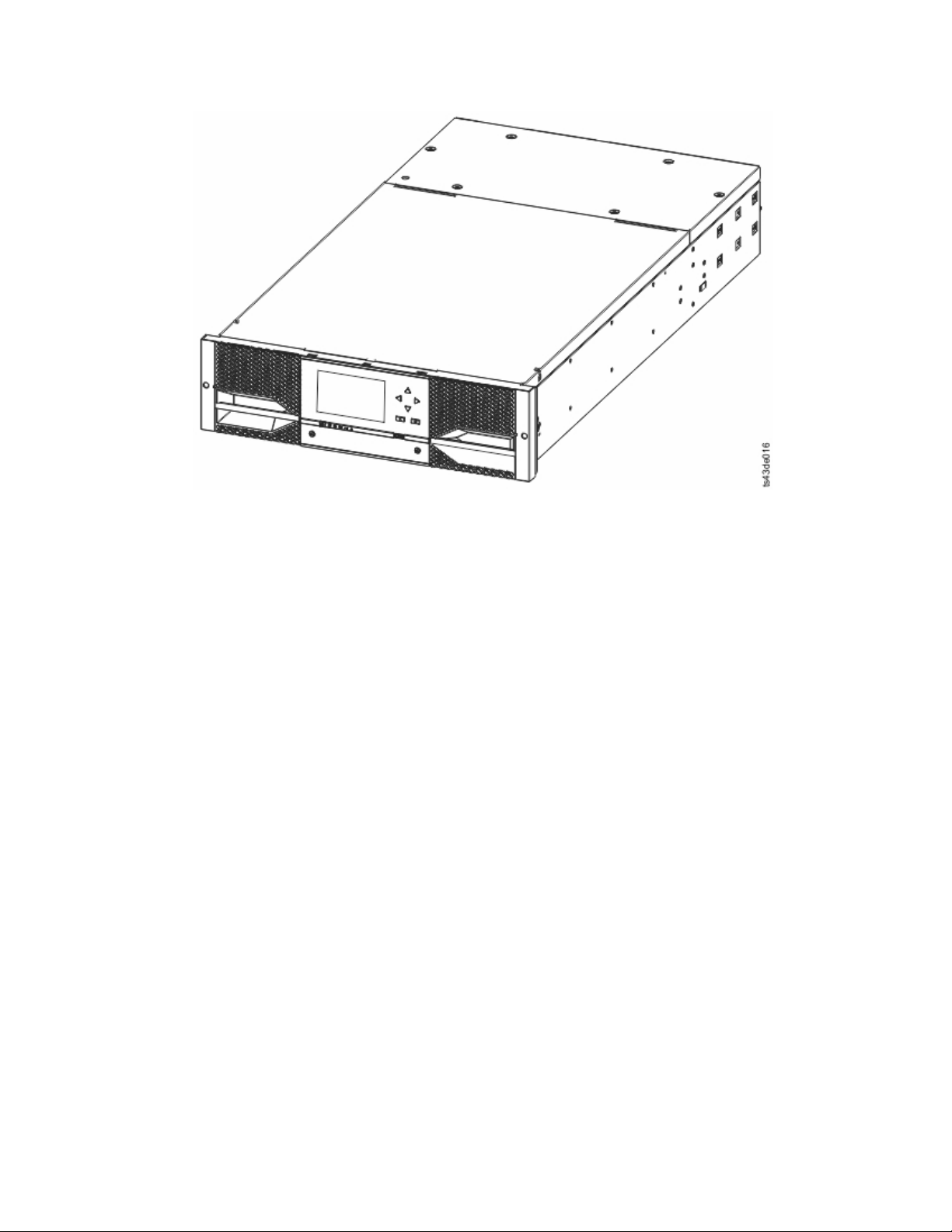
Figure 25. The module after removal from the box
Attention: Do not place a module on either the ends or sides as this action can damage the
module.
5. Unlatch the top of the module by using your fingers or a small tool, one on each side of the lid, and
press inward. When the lid is opened, remove it by pulling it forward. See Figure 26 on page 36.
Installing 35
Page 58
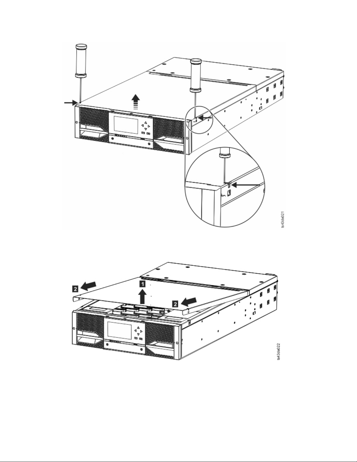
Figure 26. Unlatching the top of the module
Figure 27. Removing the top of the module
6. Remove the foam packing from the inside of the module.
36 Dell EMC ML3 Tape Library: User's Guide
Page 59
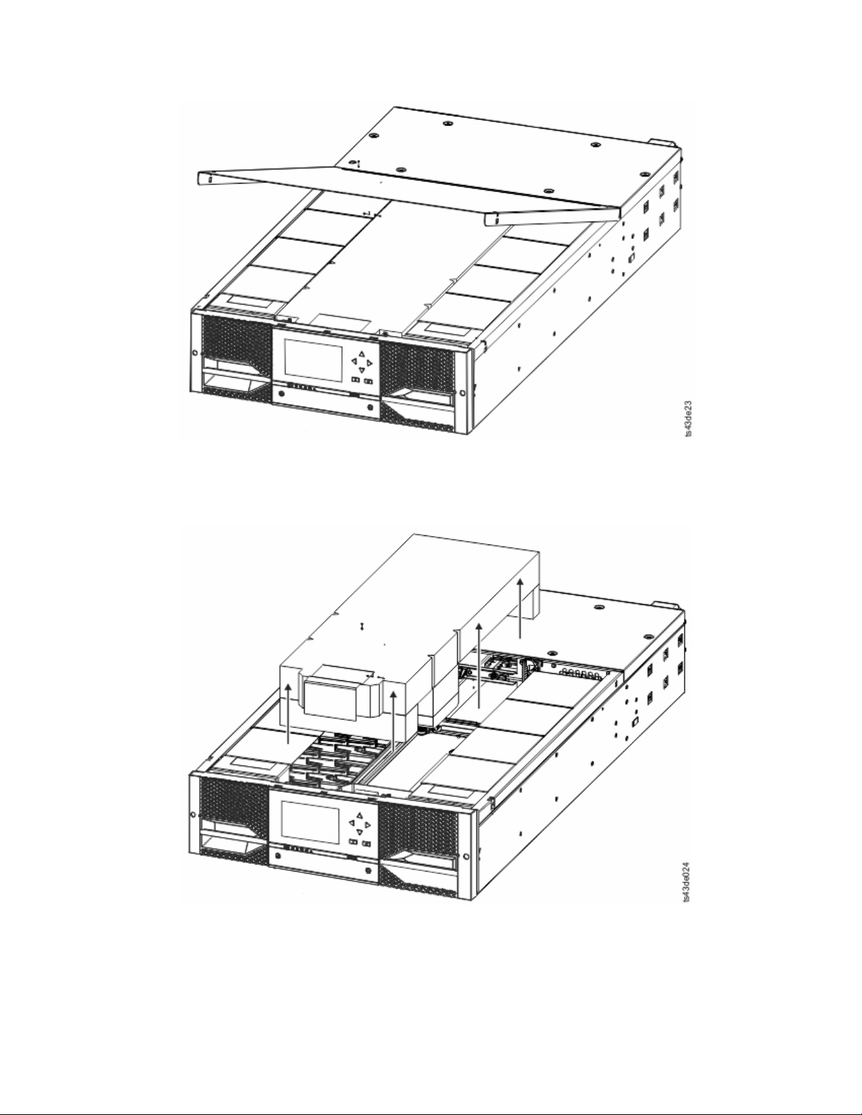
Figure 28. The module is opened to show the foam packing.
7. After the packing is removed, the internal components are shown.
Figure 29. The foam packing is removed, and the internal components are shown - Base Module.
8. Install the top cover if you do not plan to add modules above this module.
Important: The module contains a sensor that detects when the top cover is installed correctly. See
Figure 30 on page 38. If the top cover is inserted at too high of an angle, the sensor is not activated,
and a Missing Top Cover error message displays. If the top cover is inserted at a low angle, similar
Installing 37
Page 60
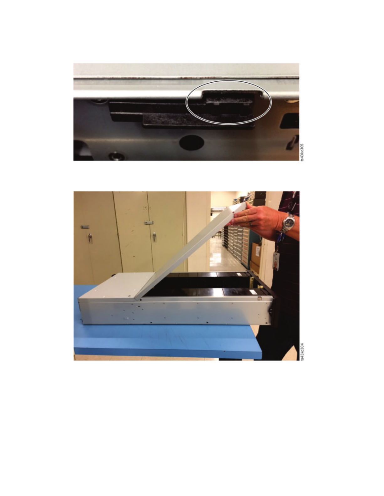
to sliding it onto the module, the sensor is activated, and no error message displays.
Figure 30. Top cover sensor
Figure 31. Incorrect top cover insertion - too high
38 Dell EMC ML3 Tape Library: User's Guide
Page 61
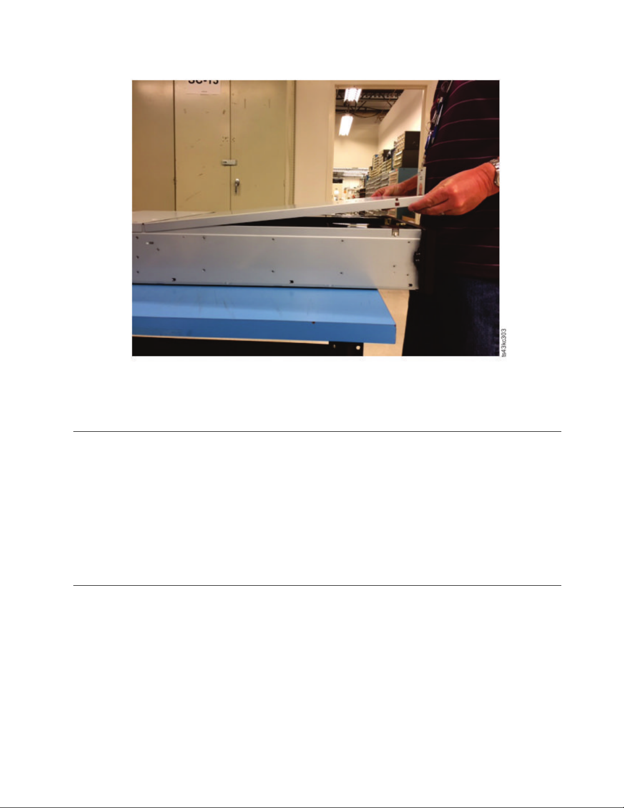
Figure 32. Correct top cover insertion
9. Save the packaging materials for future use.
10. If you are adding extra modules, go to “Preparing top and bottom modules.”
Identifying Library Module components
The Dell ML3 tape library is shipped with a rack mount kit and all cables (power and interface) when the
unit is ordered.
1. Locate one or more packing slips for your module.
2. Verify that you received each item that is listed on the packing slips.
Note: Order the power cord that matches the electrical requirements of the country or area.
For SAS libraries, you must provide SAS cabling with the correct configuration for your HBA. For Fibre
Channel libraries, you must provide one Fibre Channel cable for each tape drive.
Preparing top and bottom modules
Skip this step if you are installing a Base Module only without an Expansion Module.
The Base Module has a removable top and bottom covers.
Installing Expansion Modules above the Base Module
If you are installing one or more Expansion Modules above the Base Module, move the top cover from
the Base Module to the Expansion Module that is installed at the top of the library.
To move the library top cover plate from the Base Module to an Expansion Module
Installing 39
Page 62
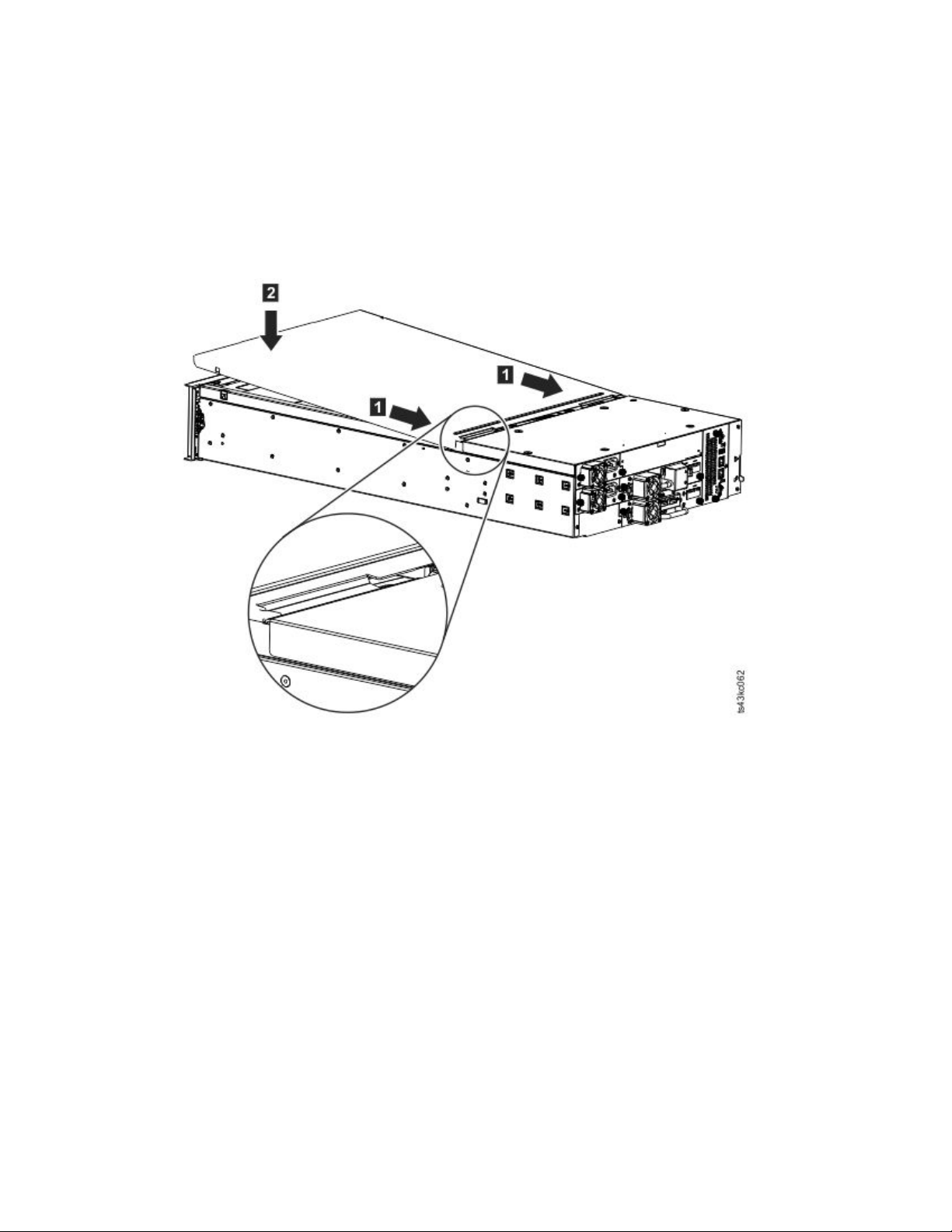
1. Remove the library top cover plate from the Base Module. See Step 5 in “Unpacking the Base Module
and Expansion Modules” on page 34.
2. Install the top cover on the Expansion Module that is installed on the top of the library.
a. Place the Expansion Module on a work table.
b. With the front of the top cover raised approximately 12 cm, engage the rear of the cover at the
Expansion Module pivot point at the back of the opening.
c. Lower the front of the top cover until the latches engage on both sides.
Figure 33. Lowering the front of the top cover
Installing Expansion Modules below the Base Module
If you are installing one or more Expansion Modules below the Base Module, move the bottom cover
from the Base Module to the Expansion Module that is installed at the bottom of the library
To move the library bottom cover plate from the Base Module to an Expansion Module
1. Remove the library bottom cover plate from the Base Module.
a. Place the Base Module on a work table.
b. Lift the unit front end by about 16 cm (use unit rear as a pivot edge).
c. Support the bottom cover with one hand. Insert a small flathead screwdriver or Torx screwdriver
into the hole and slide about 4 mm sidewards to the left to unlock the spring loaded lock. See
Figure 34 on page 41.
Important: Do NOT turn the module upside-down to complete this step.
40 Dell EMC ML3 Tape Library: User's Guide
Page 63
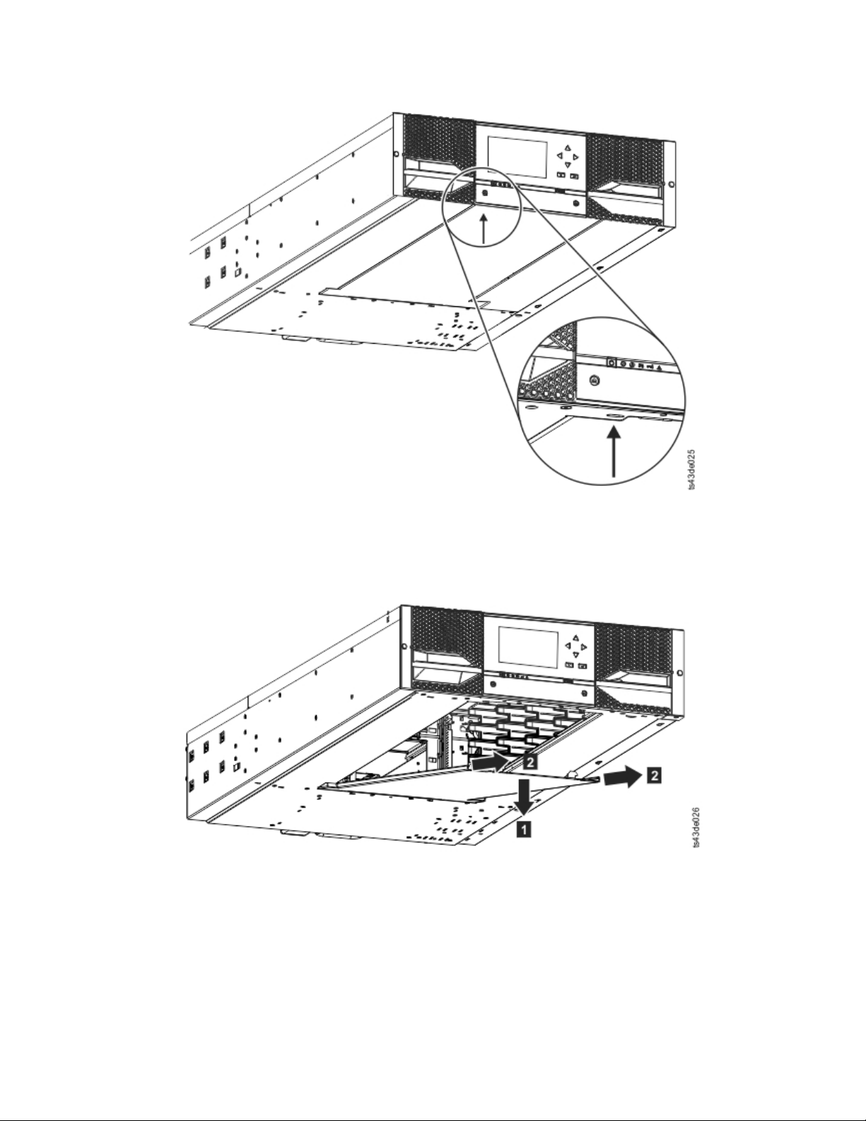
Figure 34. Unlocking the spring loaded lock
d. Lower the cover front end by about 10 cm (▌1▐) and pull gently forward (▌2▐) to disengage from
the pivot point at the unit center.
Figure 35. Removing the cover
2. Install the library bottom cover plate to an Expansion Module.
a. Place the Expansion Module on a work table.
b. Lift the unit front end by about 16 cm (use unit rear as a pivot edge).
c. Insert the bottom cover at the center
d. Lift the cover front edge until hard stop and it locks in at the unit front. The bottom cover fits
only one way.
Installing 41
Page 64
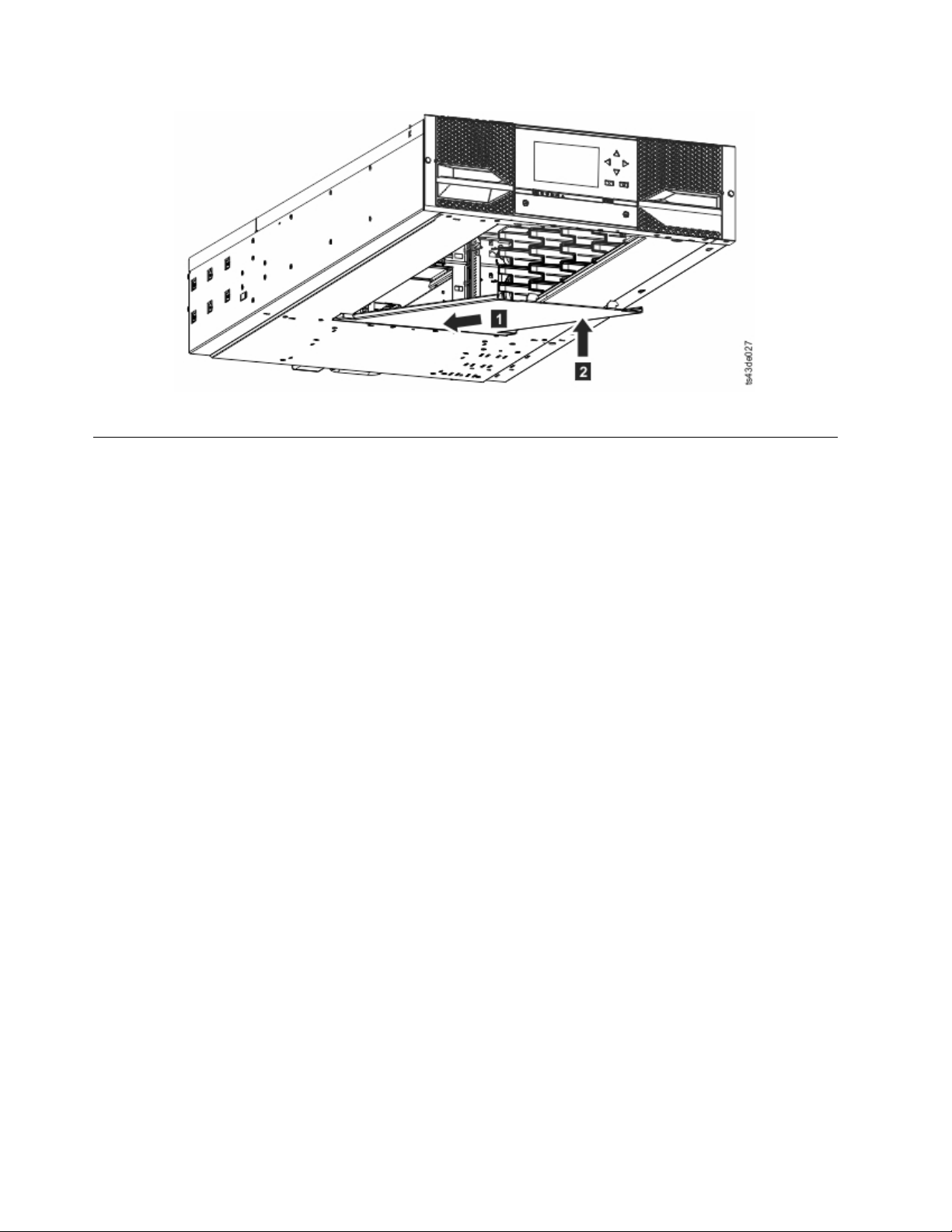
Figure 36. Lifting the cover and locking it
Installing modules in a rack
Modules are easy to install in racks that are compliant to the EIA 310A Standard, when at least 1 meter
deep. You need a #2 Phillips screwdriver for this process.
Note: Install modules from the bottom to the top. Refer to “Structure and supported library
configurations” on page 2 for the correct configuration of Base and Expansion Modules.
To locate the rail locations when multiple modules are installed.
1. Locate the bottom of the lowest full U where the lowest module is installed.
2. Continue identifying the locations for any additional module 3U higher.
To install the rails into the rack, starting from the lowest rack location.
a. Locate the four universal rack connectors, four Philips screws, and two rackmount rails (LH and
RH).
Note: The universal rack connectors have two sides, for round hole and square hole racks. The
square-hole side might be painted.
42 Dell EMC ML3 Tape Library: User's Guide
Page 65
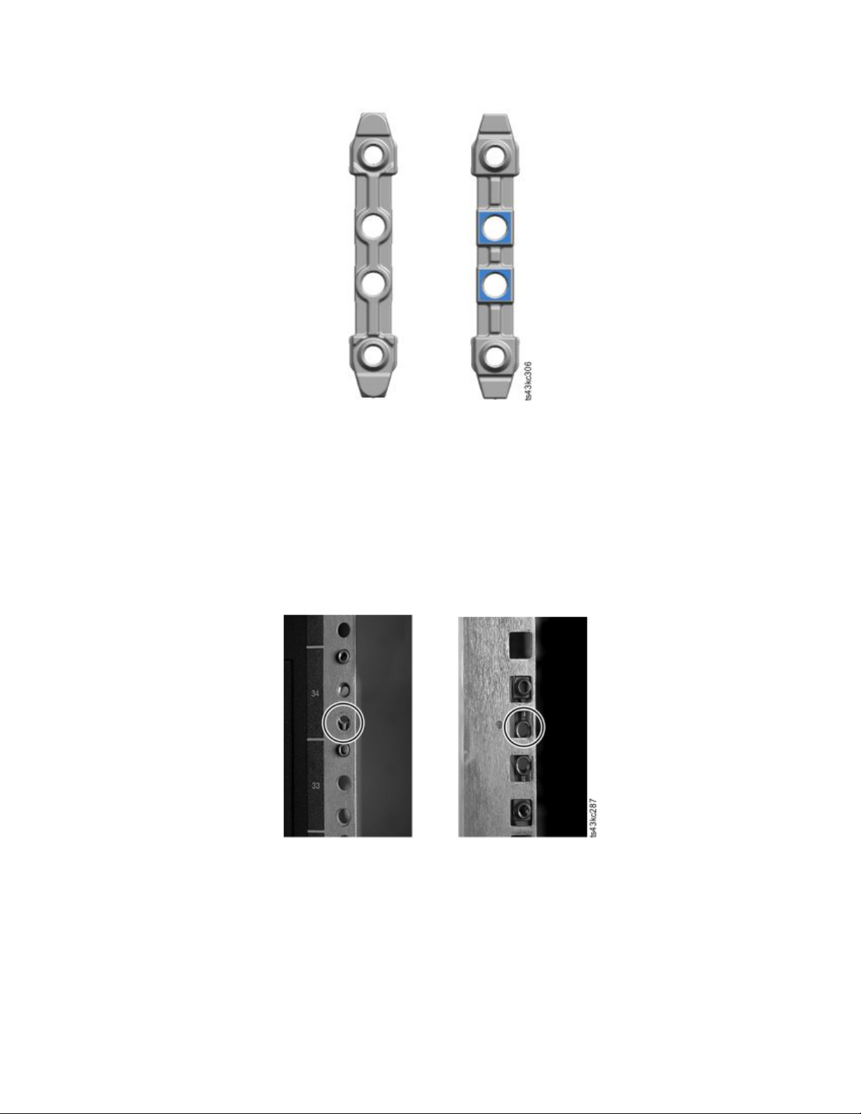
Figure 37. Universal rack connector
b. On the inside of the racks, facing out, mount the connectors at the appropriate height to the right
and left rack posts. Mount them in the middle hole of the height unit (the middle of a height unit
is the hole between two wide and neighboring division bars) in both front and back. The four
screw holes must align with the holes on your rack. If they do not, the blocks are not in the
correct location. See Figure 38 and Figure 39 on page 44.
Note: If the connectors are installed incorrectly, the screws on the connectors do not match the
holes on the frames. The circles in the graphics highlight the mismatch.
Figure 38. Incorrect connector locations
Installing 43
Page 66
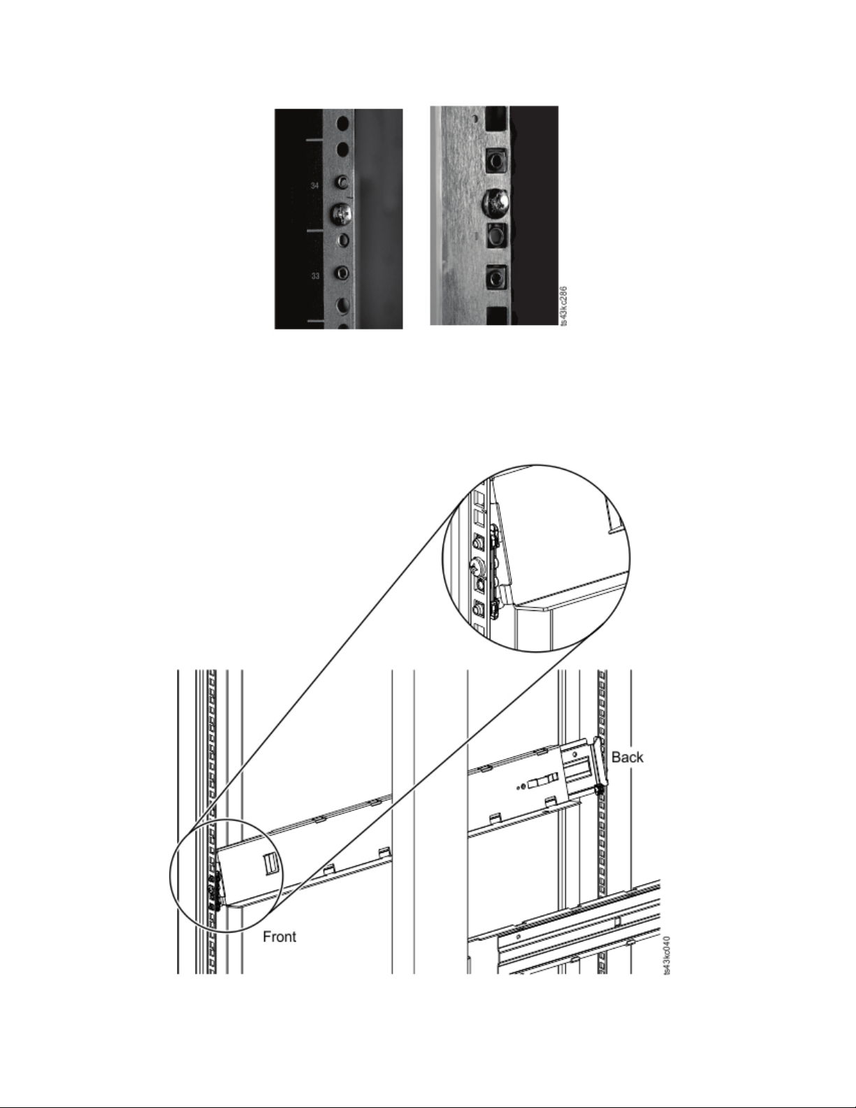
Figure 39. Correct connector locations
c. Repeat step b on the right and left rack posts in the rear of the rack.
d. Mount the LH Rackmount rail to the connectors. See Figure 40.
e. Repeat step d with the RH Rackmount Rail.
Figure 40. Mounting the rails to the connectors
44 Dell EMC ML3 Tape Library: User's Guide
Page 67

Figure 41. Side rails installed
3. Place the library at the front of the rack on the support angles of the rails and push it into the rack to
the back stop.
Figure 42. Sliding the library into the rack
4. If you are installing multiple modules, verify that this module is installed directly above or below its
adjacent module and is contained within the correct 3U volume. Remove the tape that is covering the
alignment pin lock/unlock lever on the rear of each module. The gap between modules must be less
than 4 mm.
Installing 45
Page 68
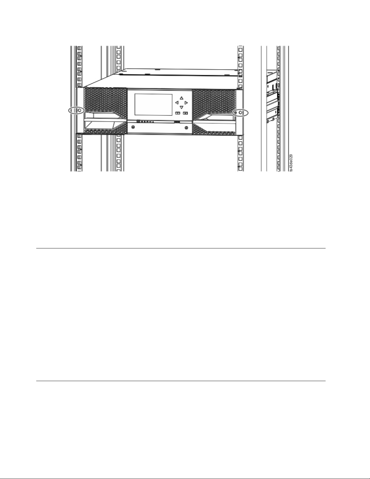
Figure 43. Library in the rack
Important: Each module must be on its own rails.
5. With a Phillips screwdriver, loosely screw the module to the front of the rack, one screw on each side.
See the circled areas in Figure 43.
6. Align the module as needed. Then, tighten the screws on each side of the module. See “Aligning and
connecting modules.”
7. Repeat steps 2 - 6 to install the rest of the modules into the rack.
Installing a tabletop module
Installation of a one module library (Base Module only) can be completed without special hardware.
If you unpacked a Table Top Module, confirm that you received the following components:
1. Base Module
2. Accessory Kit
v One North American power cord
v One European power cord
1. Remove the Base Module from the box.
2. Open the cover and remove the foam packing from inside the enclosure. See “Unpacking the Base
Module and Expansion Modules” on page 34.
3. Replace the cover.
4. Set the Base Module in the wanted location. Ensure that it is level.
5. Plug in the power cord and the connecting cables.
Aligning and connecting modules
Skip this step if the library does not have Expansion Modules.
Aligning the modules ensures that the accessor can move freely between the modules. The library cannot
operate unless the alignment mechanisms of the upper modules are in the locked position, and the
alignment mechanism of the lowest module is unlocked.
46 Dell EMC ML3 Tape Library: User's Guide
Page 69
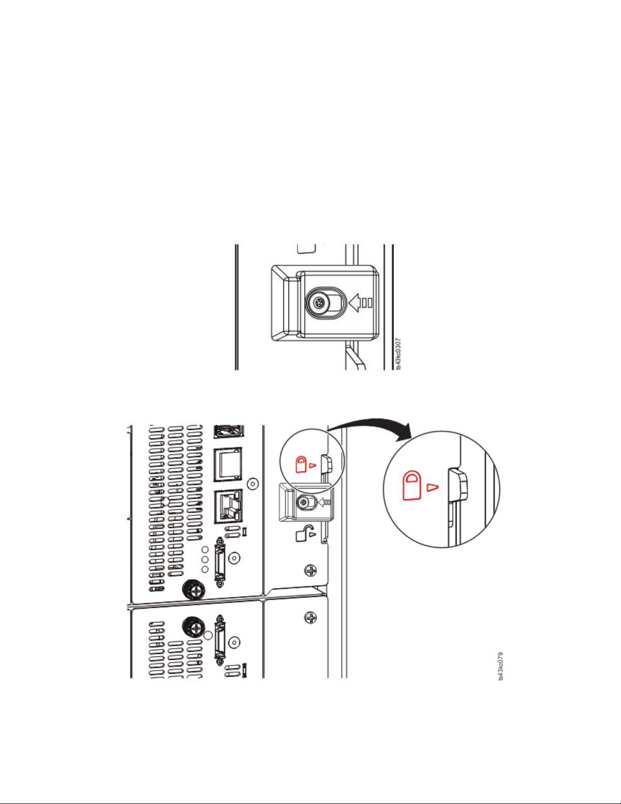
1. From the front of the library, loosen the screws on each of the modules where they are attached to the
rails two full turns.
2. From the back of the library, starting with the bottom pair of modules, align each module with the
module below it. Repeat for each pair of modules. Refer to Figure 45.
a. Move the alignment lever of the upper of the pair of modules to the locked or engaged position. If
you encounter resistance, adjust the position of the upper module so the pin in the alignment
mechanism moves into the mating hole in the lower module.
Note: If a blue alignment lever lock is attached to the rear of the module, slide it to the left, then
move the alignment lever. The lever lock has an internal spring, so hold it while the alignment
lever is moved, and it automatically springs back into place after the lever is moved. See
Figure 44.
Figure 44. Alignment lever lock
Figure 45. Alignment lever locked or engaged to lower module
Installing 47
Page 70
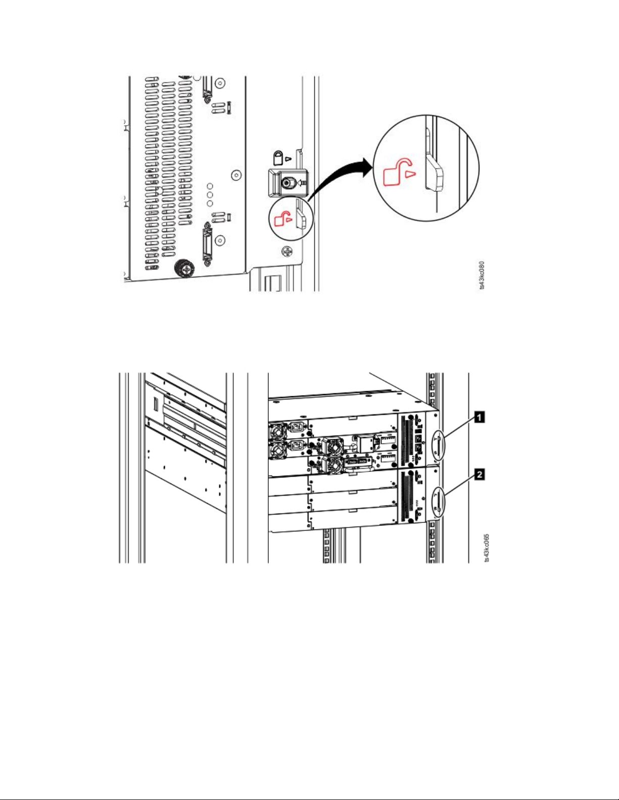
Figure 46. Alignment lever unlocked or disengaged
3. Verify that the lowest module in the library has its alignment lever is in the unlocked or disengaged
position.
Figure 47. Two modules in rack, seen from the rear
▌1▐ Locked
▌2▐ Unlocked
4. From the front of the library, tighten the Philips screws on each of the modules to secure the modules
to the rack.
5. From the back of the library, connect the modules of each pair to its adjacent module by using the
expansion interconnect cables (▌1▐) as shown in Figure 48 on page 49.
Note: The top module's top connector and the bottom module's bottom connector has nothing
plugged into them.
48 Dell EMC ML3 Tape Library: User's Guide
Page 71
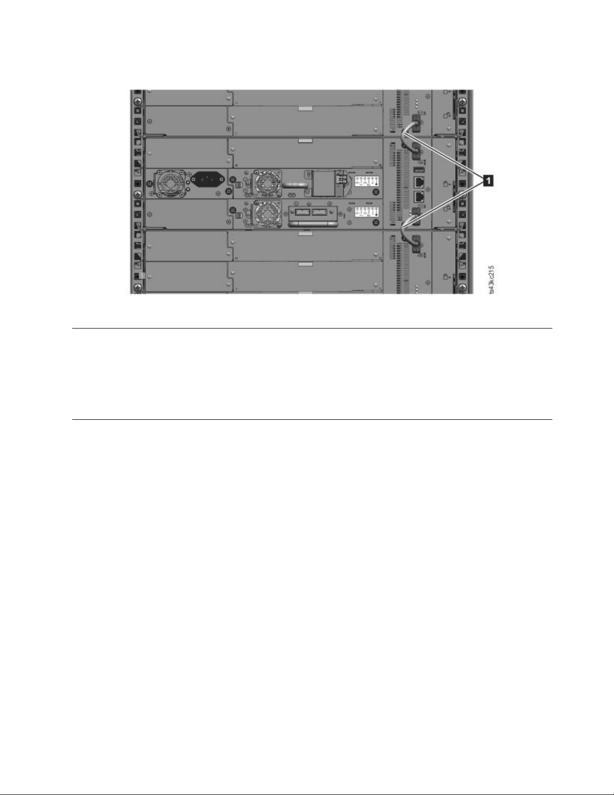
Figure 48. Connected modules
Validating tape drive installation
Tape drives come already installed in the library modules.
v Half-height tape drives can be installed in any drive bay in a module.
v Full-height tape drives must be installed in the lowest two bays of a module. Installing a full-height
drive in the top two bays of a module is not supported.
Connecting cables
Connecting Fibre Channel cables
Installing 49
Page 72
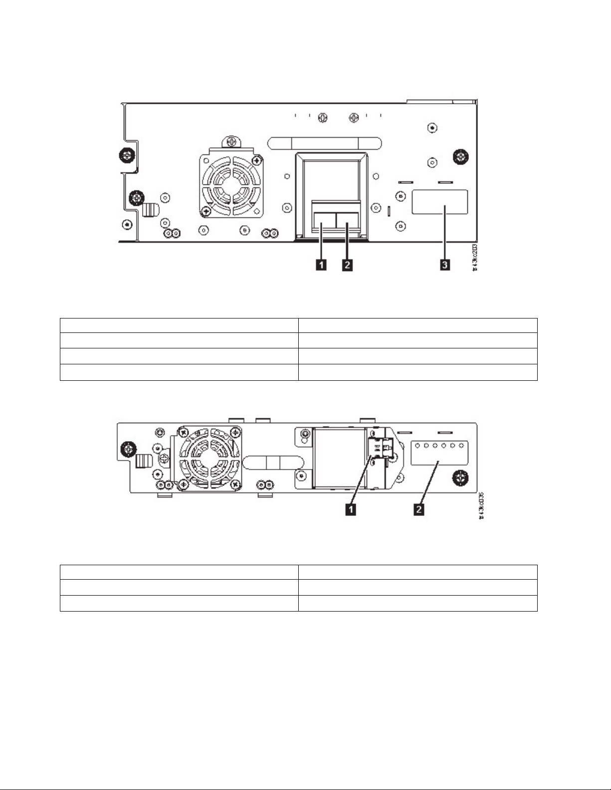
1. Remove the FC port caps if necessary. Attach one end of the FC cable to port 0 on the tape drive.
Figure 49. Full-height FC dual port
Table 23. Full-height FC dual port
Number Description
▌1▐ FC port 0
▌2▐ FC port 1
▌3▐ Drive sled indicators (see Figure 18 on page 13)
Figure 50. Half-height FC single port
Table 24. Half-height FC single port
Number Description
▌1▐ FC port 0
▌2▐ Drive sled indicators (see Figure 18 on page 13)
2. Attach the other end of the FC cable to a switch or HBA.
3. Repeat the same process with port 1 if you have a dual port drive.
Connecting SAS cables
1. Attach the end of the SAS cable into the connector on the HBA. If you are using a SAS
fanout/Interposer cable, the end of the cable with only one connector must be plugged into the HBA.
2. Connect the drive end of the cable.
50 Dell EMC ML3 Tape Library: User's Guide
Page 73
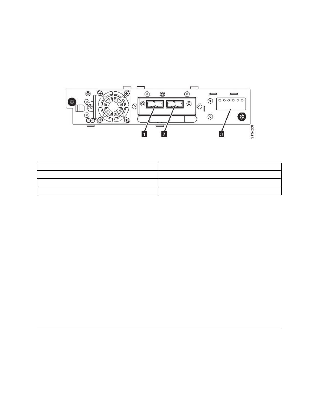
v If you are using a cable with a single connector on each end, attach the other end into the
connector on the tape drive.
v If you are using a SAS fanout/Interposer cable, attach one mini-SAS connector into the connector
on each tape drive. The unused ends of the SAS fanout/Interposer cable are single channel and not
suitable for use with disk arrays. Use the other ends to connect tape drives, or coil and secure them
to the rack to minimize stress on the connectors.
Figure 51. Half-height SAS dual port
Table 25. Half-height SAS dual port
Number Description
▌1▐ SAS port 0
▌2▐ SAS port 1
▌3▐ Drive sled indicators (see Figure 18 on page 13)
Note: SAS signal rates require clean connections between the HBA and tape drive. Do not use adapters
or converters between the HBA and the tape drive. For reliable operation, use a maximum SAS cable
length of 6 meters.
Connecting USB cables
Two USB ports are on the library, one in the front and one in the rear. USB connections are used by
service personnel for diagnostic and service procedures. Attach one end of the USB cable to your
notebook or other device and the other end to the front or rear USB port of the library.
Important: USB cable lengths of more than 3 meters are NOT supported for the front or rear USB ports.
Connecting Ethernet cables
To use the Management GUI, connect an Ethernet cable from the bottom Ethernet port on the Base
Module controller to your network. See “Rear panel” on page 8 for the location of the Ethernet ports.
Note: Ethernet port A (bottom Ethernet port) is the primary port. The second Ethernet port, Port B, is for
redundancy.
Powering on the library
1. Plug the power cables into the power connectors on each module and into power outlets.
Notes:
v The library has dual redundant power supplies. To increase redundancy, plug each power cord into
a different AC power circuit.
Installing 51
Page 74
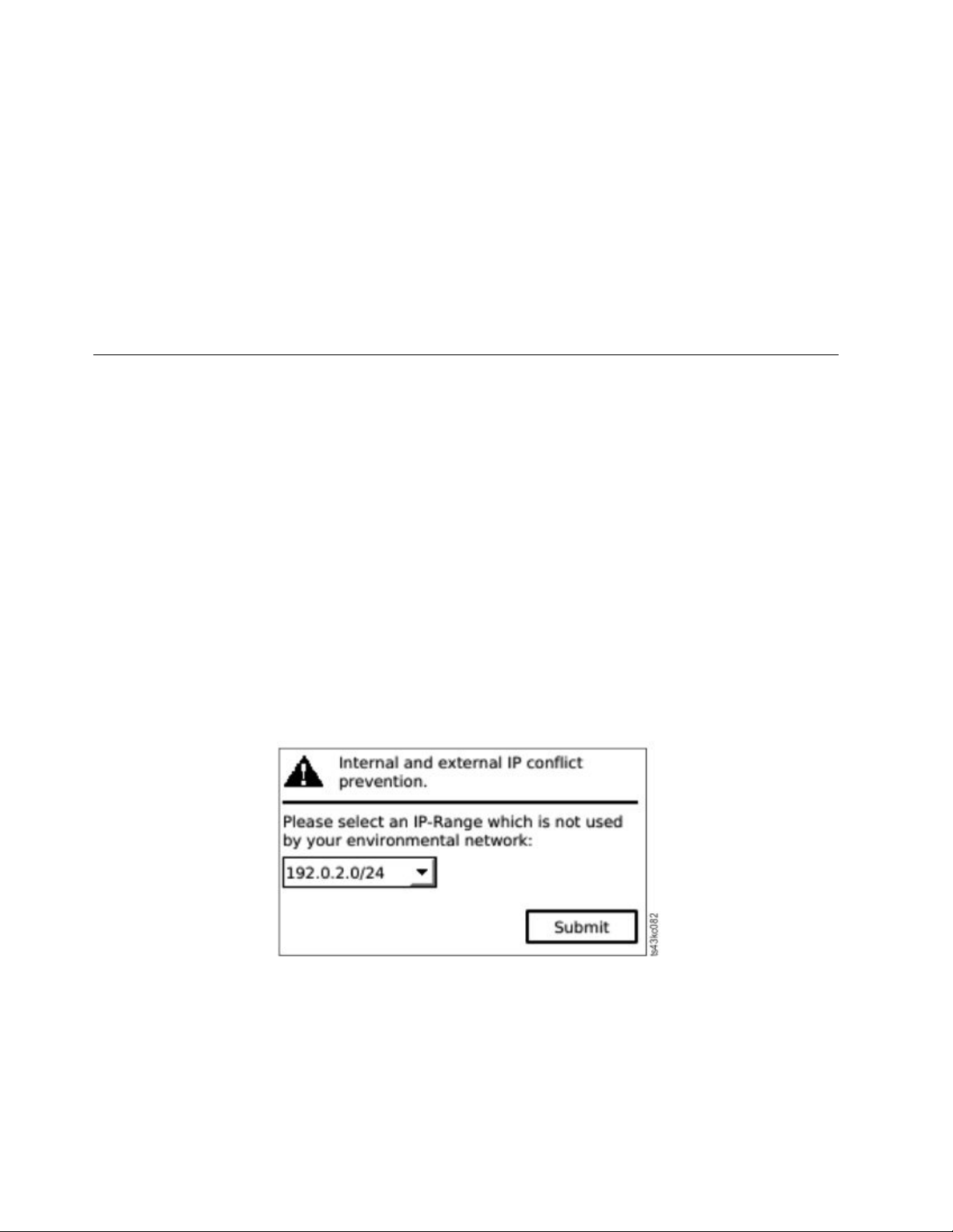
v A power supply is required in expansion modules if drives are installed.
2. Power on the library by pressing Power on the Base Module just below the Operator Panel and hold
for 5 seconds. See “Front panel” on page 7 for the location of the Power button. When the library is
powered on, it
a. Inventories the tape cartridges in the magazines,
b. Checks the firmware version on all modules,
c. Configures the tape drives.
d. Confirms the presence of the existing modules,
e. Searches for any new modules.
f. When the library is powered on for the first time, the Initial Setup starts. See “The Initial Setup
process.”
The Initial Setup process
When you turn on the library for the first time, the Initial Setup process starts automatically. Click Next
to start the process. The wizard guides you through setting the Internal IP range, setting library network
configuration, configuring date and time, and setting the administrator PIN. You can skip items and stop
the wizard at any time. After you configure the network settings, you can start the wizard from the
Management GUI to complete more configuration items.
Notes on navigation and entering data into the Operator Panel
v The arrow keys on the front panel are used to select numeric and alphanumeric characters and
symbols. Capital and lowercase letters, numbers, and punctuation are available to use.
v The right button under the arrows is Enter, which is pressed before you enter text.
v The left button under the arrows is Back/Return, which is used to delete entries.
See Figure 56 on page 62.
When the library starts up for the first time, the initial setup automatically begins.
1. Enter the IP address for your library. See “IP range selection” on page 31.
Figure 52. IP address selection
2. Press Enter to unlock the Operator Panel.
Note: If you wait too long to make your selection, the unit auto calibrates. The auto calibration
finishes, then returns you to the login screen.
3. When you are logged in, the initial configuration process begins with Network Settings.
4. Follow the prompts to set date and time, and administrator PIN.
52 Dell EMC ML3 Tape Library: User's Guide
Page 75

5. When the initial setup is complete, the display returns to the Operator Panel main screen.
To check your configuration at any time, go to Configuration > Initial System Setup on the Operator
Panel. On the Management GUI, go to Library.
Initial configuration and customization
After the physical installation and initial setup by using the Operator Panel is completed, an
administrator can log on to the Management GUI to complete the library configuration and configuration
of any additional features.
Upon the first login with the user role: admin and password: adm001, The Initial Configuration Wizard
guides you through basic configuration settings.
The library has many features to customize it for your organization. Go to “Locating Management
functions” on page 63 to customize your library with these features.
v Enabling or disabling the I/O station.
v Naming the library with the Manage Logical Library function.
v Creating or managing Logical Libraries. See “Library sharing” on page 17 for information.
v Enabling and configuring SNMP network management.
v Setting up email event notification.
v Setting up encryption.
v Configuring date and time.
v Enabling or disabling Library Auto Clean. See “Methods of cleaning drives” on page 69.
Labeling and loading tape cartridges
The library can power on without cartridges, but needs cartridges before it can complete data read and
write operations, or any tests or operations that transfer cartridges.
Bar code labels are highly recommended in production environments to improve inventory time in the
library and ease cartridge-handling processes outside the library. See “Labeling tape cartridges” on page
145.
The I/O station
If the I/O station is enabled, you can use it to load cartridges into the library. Press the magazine button
for less than 3 seconds and after the button LED is flashing fast, pull out the I/O station.
Installing 53
Page 76
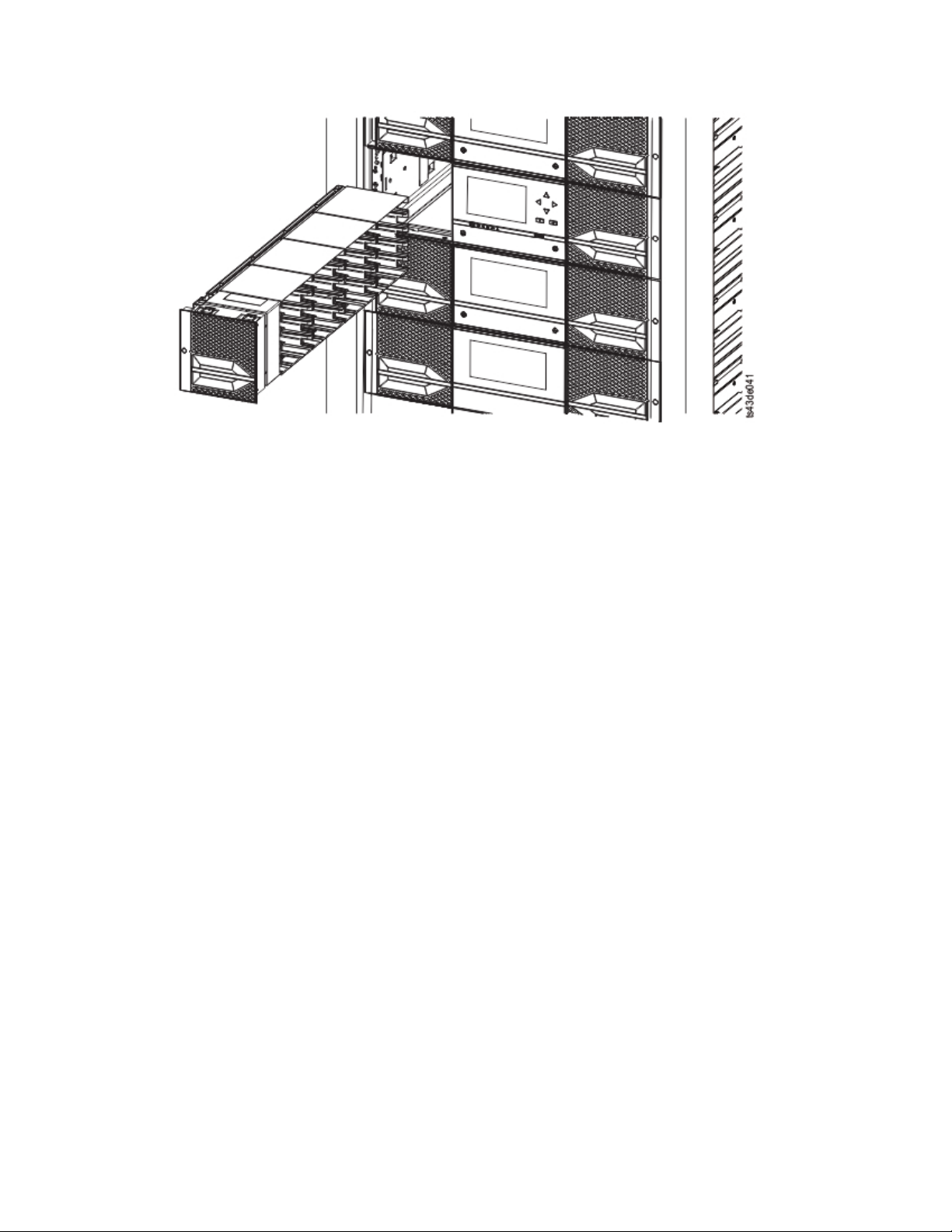
Figure 53. Open I/O station seen from the left
Important: The lowest I/O slot of the lowest module in a library is inaccessible to the accessor, so the
I/O Station of the lowest module has four slots instead of 5.
Bulk loading magazines
1. Unlock the magazine by pressing the magazine button for more than 3 seconds, wait for the button to
flash fast and then pull out the magazine.
a. From the Operator Panel or Management GUI, select the module and then select Open Magazine.
You can also press the release button on the front panel of the module to release the magazine.
b. Wait until the magazine is unlocked, and then pull out the magazine.
Note: Wait for the Operator Panel/Management GUI message to say that the magazine is
unlocked before the magazine is pulled out.
54 Dell EMC ML3 Tape Library: User's Guide
Page 77
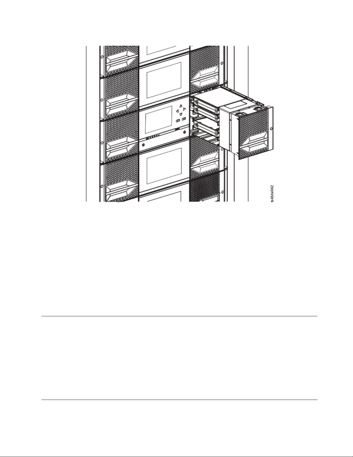
Figure 54. Magazine pulled out
2. Load the tape cartridges into the magazine.
Important: The lowest slots of the lowest module in a library are inaccessible to the accessor, so do
not load cartridges into these cartridge slots.
3. Insert the magazine into the unit.
4. Push the magazine handle slowly until the magazine release latch snaps into place. The magazine
locks into place.
Important: Push the magazine fully into place until the latch snaps into place.
5. Repeat steps 1 - 3 for each of the other magazines.
See “Accessing cartridges” on page 70.
Verifying the installation
Verify that the library has the current firmware revision. The library firmware revision is displayed at
Library > Actions > Properties.
1. Verify library firmware and update if needed: Library > Actions > Update Library Firmware
2. Run Library Verify.
3. Save the configuration settings to a file on your computer from the Management GUI: Settings >
Library > Advanced > Save Configuration File.
Having a backup of the library configuration is helpful when the library is recovering from a
configuration error or needs service.
Advanced library configuration
To create and manage multiple logical libraries, utilize the advanced logical library function.
Installing 55
Page 78

Overview
Multipath architecture
The multipath architecture feature of this tape library allows Open Systems applications to share the
robotics of the library. See “Library sharing” on page 17 for information.
The library features storage area network (SAN) ready multipath architecture. This architecture allows
homogeneous or heterogeneous Open Systems applications to share the library's robotics without
middleware or a dedicated server (host) acting as a library manager. The SAN-ready multipath
architecture makes sharing possible by partitioning the library's storage slots and tape drives into logical
libraries. Servers can then run separate applications for each logical library. This partitioning capability
extends the potential centralization of storage that the SAN enables. Partitioning also provides investment
protection if your application does not support the mixing of drive generations and media in the same
logical library.
The multipath architecture of this library is designed to provide the capability to share the library
robotics. The sharing is accomplished first by partitioning the library into multiple logical libraries (up to
the number of drives installed). Then, each logical library is assigned its own separate and distinct drives,
storage slots, and control paths. Input/output (I/O) slots are shared on a first-come-first-serve basis. This
type of partitioning is designed to allow heterogeneous applications to share the library robotics
independent of each other. Cartridges under library control are not shared between logical libraries, nor
are they allowed to be moved between logical libraries. An example of heterogeneous sharing is a
Microsoft Windows application that is using the drive and storage slots of one logical library, while a
UNIX application uses the drive and slots of another logical library. See “Mixed drives” on page 12.
Multiple logical libraries
A library can be partitioned into multiple logical libraries to enable simultaneous data backup and restore
tasks from different applications. For example, you can create multiple logical libraries so that is
processes
v Commands from Application 1 (about Department A) in Logical Library 1
v Commands from Application 2 (about Department B) in Logical Library 2
v Commands from Application 3 (about Department C) in Logical Library 3
In this configuration, the tape drives and cartridges of each logical library are dedicated to that library
and are not shared among other libraries and subsequently other applications. Commands that are issued
by the applications travel to the library through three unique control paths. So, the data processing for
Department A is confined to the tape drives and cartridges of Logical Library 1. Processing for
Department B is confined to the tape drives and cartridges of Logical Library 2, and so forth.
For applications that do not support mixed drive types and media within the same logical library,
partitioning the library into multiple logical libraries provides the capability to keep them separate. For
example, you can partition the following tape drives and their media into multiple and separate logical
libraries:
v LTO 8
v LTO 7
v LTO 6
Multiple control paths
With this tape library's multipath architecture, in addition to creating multiple logical libraries, you can
configure any logical library to have more than one control path. A control path is a logical path into the
library through which the library receives standard SCSI Medium Changer commands to control the library
operations.
56 Dell EMC ML3 Tape Library: User's Guide
Page 79

Multiple control paths reduce the possibility of a failure in one control path to cause the entire library to
become unavailable. Also, when you configure more control paths, more library-sharing configurations
and options are possible. Access to the library is on a first-come, first-served basis. Each control path for a
logical library can accept commands while the library is in use by another control path.
Multiple control paths for control path failover
This tape library offers an optional control path failover feature. See “Library sharing” on page 17 and
“Path failover and load balancing” on page 18.
Use of the control path failover feature further reduces the possibility of a failure in one control path to
cause the entire library to become unavailable.
The control path failover feature (feature code 1682) enables the host device driver to resend a command
to a different control path for the same logical library.
Library partitioning
Libraries that contain at least two drives can configure two logical libraries. It is possible to configure up
to 21 logical libraries in the library (up to the number of drives installed). In a partitioned library, the
Operator Panel reports only the status of logical library 1 in the main menu because of space limitations.
The user must go to the logical libraries status in the Operator Panel to get the information about the
additional library partitions. The Management GUI provides a Logical Library Graphical View.
Partitioning of libraries
With full-height or half-height physical drives, physical numbering is bottom up for all drives. For
example, if you replace a half-height drive in Figure 22 on page 16, the drives are still numbered 1-4. If
you add a drive in any of the slots in between drives numbered 1 and 4, the physical numbering changes
and is still numbered bottom up.
Important: A full-height drive can be installed in a module in the lower two slots only.
Configuration of a 1-logical library system
A one logical library system contains all drives present in any drive positions, and it contains all the slots.
Configuration of multiple logical libraries
A library with multiple logical libraries must have a drive for each logical library and at least one slot.
Drives can be in any location in the library. It is best to have drives that are located near the slots that are
assigned to the same logical library to minimize accessor movement and maximize performance.
SCSI element-addressing
A logical library assigns SCSI element addresses to drives, storage slots, I/O slots, and the accessor. For
each element type (drive, storage, I/O), the SCSI element address can be viewed on the Management
GUI.
While SCSI addressing follows the same method as physical location-numbering, this action depends on
the Advanced Logical Library configuration.
Drive numbering is from bottom to top. Storage slot-numbering is from left magazine (front to back,
bottom to top) to right magazine (back to front, bottom to top). IO slot-numbering is from bottom to top.
Accessor is single number.
Installing 57
Page 80

Note: When the number of drives in your library are reduced, update the logical library configuration.
This action removes all event notifications that indicate a drive is missing.
Updating the logical library configuration might change the SCSI element addressing.
Verifying the host connection
To verify the connections between the host computer and the library
1. Install the application software and drivers that are compatible with the library. Backup software
packages might require extra software or licensing to communicate with the robotics.
2. Verify the connection between the library and the host by using the host server’s operating system
utilities. Or, use the Tape Diagnostic Tool (ITDT) to verify the communication between library and
host. See “The ITDT firmware update, dump retrieval and drive test tool ” on page 77.
See “Host connectivity” on page 20 for compatible servers and software.
58 Dell EMC ML3 Tape Library: User's Guide
Page 81

Managing
Certain user roles can perform different functions.
v The Admin role has access to all menus except those menus that are restricted to Service only. The
default password is adm001.The Admin account has access to monitor, configure, and run unit
diagnostics (only exception is the advanced diagnostic procedures that are reserved for service
personnel only).
v Superuser - The Superuser role has access to most sections. The default password is sup001.
v Monitor - Normal user level - The Monitor role has viewing privileges to the unit, but is not able to
make configuration changes.
v Service - Service personnel user level - Access to this level is for Service personnel only. Service
personnel have access to all menus. The Service account has all the same privileges as the Admin
account with the addition of advanced unit diagnostic procedures.
Note: User and Superuser accounts must be enabled by the library administrator. These accounts are
disabled by default.
The Management GUI
With the Management Graphical User Interface (GUI), you can monitor, configure, and operate most
library functions from a web browser.
When possible, it is recommended that the Management GUI be used as the primary library interface.
The web interface provides access to more features, includes online help, and is easier to use.
Before the Management GUI can be used, you must log in and configure the library network settings
with the Operator Panel. This action can be done during Initial Setup. See “The Initial Setup process” on
page 52.
Logging in with the Management GUI
1. Open a supported web browser and enter the IP address of the library in the browser’s address bar.
2. Select the user level and enter the password. Click Login.The ML3 RMU screen shows Welcome: User,
superuser, admin, or service after a successful login. The user can log out at any time by clicking the
"logout" text in the upper right corner of the RMU page.
Note: For initial login, select Adminstrator and the password is adm001.
Note: Only one person (on Operator Panel or Management GUI) can be logged in to the library at a time.
Any time that you try to log in and another person is already logged in, a dialog box appears, asking if
you want to log off the other user.
The Library main screen on the Management GUI
The library main screen is organized into the following regions:
59
Page 82
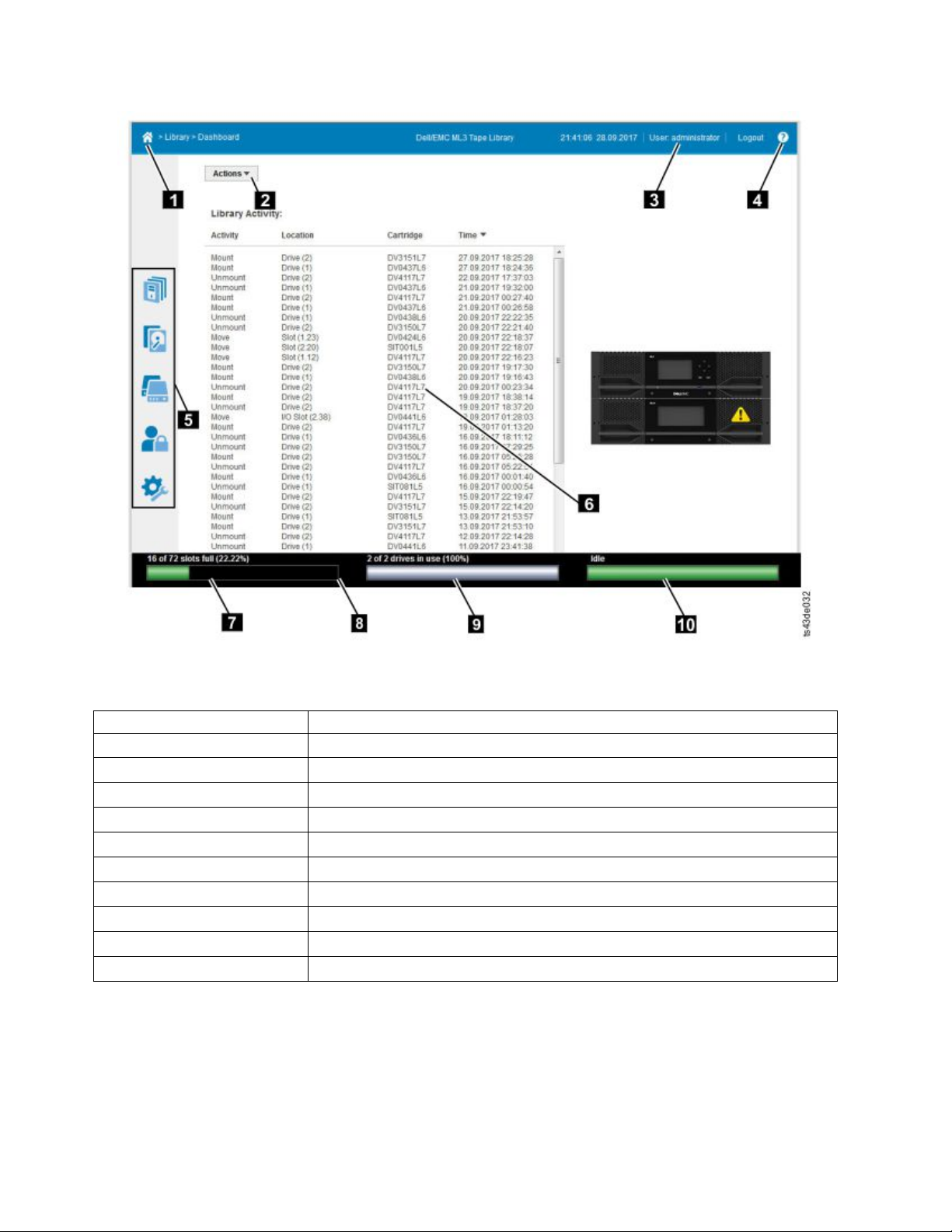
Figure 55. Management GUI main screen
Table 26. Main screen elements
Element
▌1▐ Home icon > Current Navigation
▌2▐ Actions > dependent on current navigation
▌3▐ User logged in
▌4▐ Help
▌5▐ Navigation Dock
▌6▐ Overview - dependent on current navigation
▌7▐ Physical Capacity
▌8▐ Status Bar
▌9▐ Drive Activity
▌10▐ Library Status
Tips:
1. For specific management function navigation, see “Locating Management functions” on page 63.
2. Check the online help in the Management GUI for additional information. The help pages are
updated with firmware updates and often contain up-to-date technical details that might not be
contained in this document. To access Management GUI help, click the ? icon on the right side of the
Management GUI top banner.
60 Dell EMC ML3 Tape Library: User's Guide
Page 83
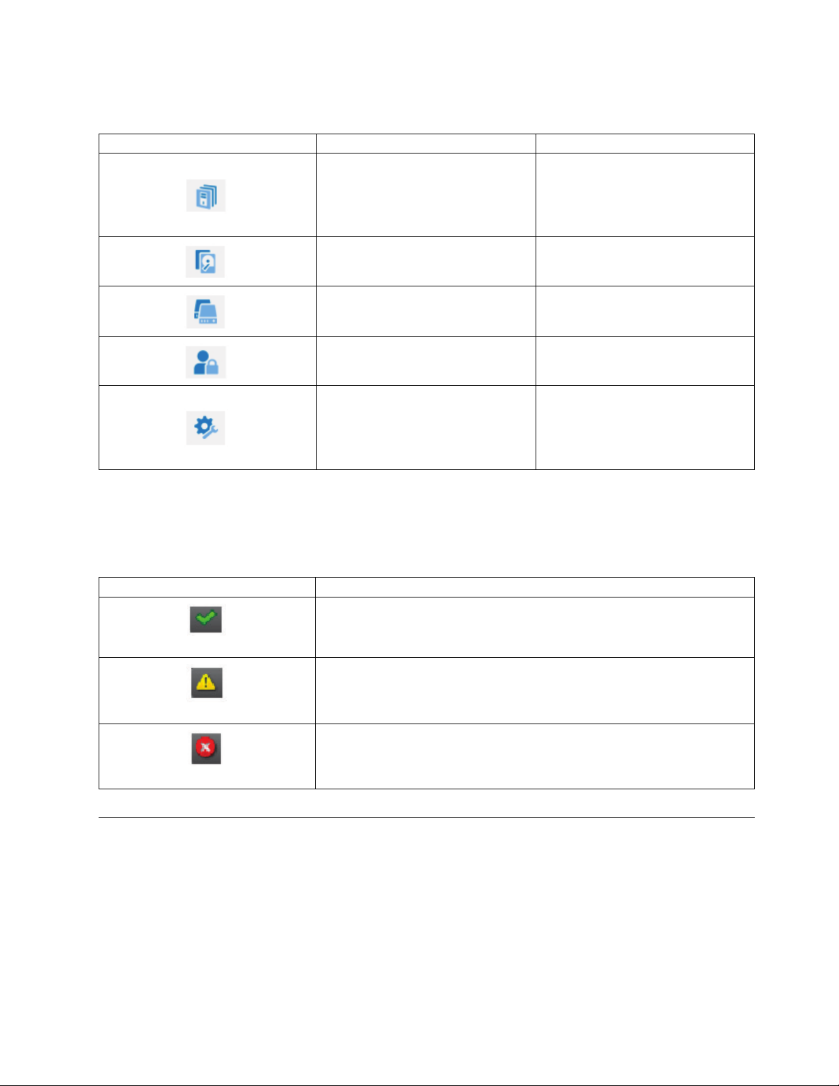
Navigation Dock
Table 27. Navigation Dock
Navigation Dock Icons Element Additional menus
Library
Drive Drives and Ports
Cartridges Cartridges and Slots
Access Users
v Dashboard
v Modules and Magazines
v Logical Libraries
v Events
Settings
Status icons
Status icons indicate the following conditions.
Table 28. Status icons
Icon Description
The green OK icon indicates that the library is fully operational and that no
user interaction is required.
The yellow exclamation point Warning icon indicates that user attention is
necessary, but that the device can still complete most operations.
The red X Error icon indicates that user intervention is required and that the
device is not capable of completing some operations.
v Library
v Network
v Notifications
v Security
The Operator Panel
The Operator Panel has a Power button, an LCD display, six navigation buttons, and five LEDs. With the
Operator Panel you can monitor, configure, and operate most library functions from the library front
panel. To use the Operator Panel, you must use the six navigation buttons (up/down, left/right, Enter,
Back). The Operator Panel is not a touchscreen. See “Front panel” on page 7 for the location of the
navigation buttons.
Operator Panel screens
Managing 61
Page 84
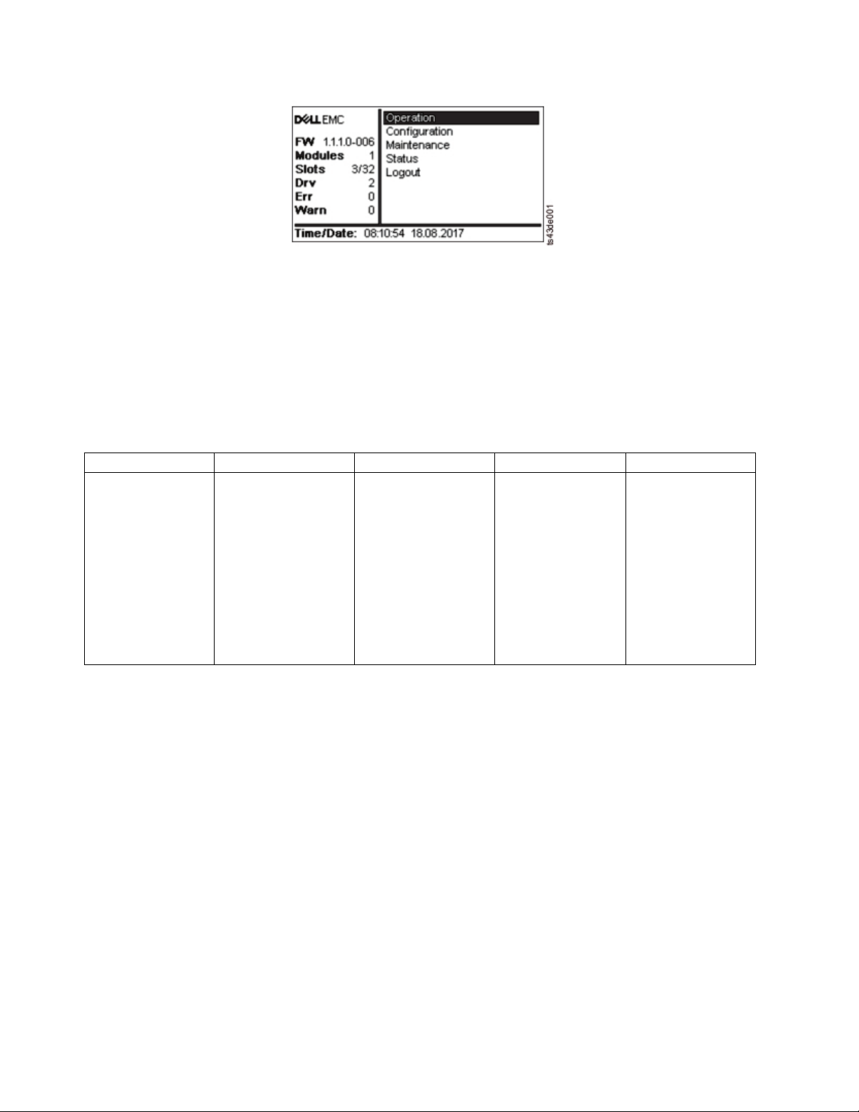
Figure 56. Operator Panel main screen
Operator Panel main screen layout
v Left Pane - Displays the library status (firmware revision, number of modules, number of slots, number
of drives, number of errors, number of warnings.
v Center Pane - Provides access to operate, configure, and log out of the library and to view more status
information (Operation, Configuration, Maintenance, Status).
v Bottom Pane - Displays more status information (library status, time/date, IPv4, or IPv6 address). The
status pane displays one status information for 10 seconds and then switches to the next status item.
Table 29. Operator Panel menu tree
Operation Configuration Maintenance Status Logout
Move Cartridge
from Drive
to Home Slot
Initial System Setup
Date & Time
Network Settings
User Accounts
Reset
Library Tests
View Events
Drive Logs
Download
Library Logs
Download
Drive Firmware
Upgrade
Library Firmware
Upgrade
LCD Adjustment
SSH (Secure Shell)
Network Settings
Library
Drive
Logout
The Operator Panel provides a subset of menu items that are compared to the full capability of the
Management GUI. For the operations that are available on the Operator Panel, see “Locating
Management functions” on page 63.
Accessing the library with the Operator Panel
The Operator Panel can be accessed in two ways, with a PIN or without one.
1. If the Operator Panel screen saver is on, press Enter.
2. If no PIN is configured, press Enter.
3. If a PIN is configured, enter the PIN, then select Login and press Enter.
Status icons
62 Dell EMC ML3 Tape Library: User's Guide
Page 85
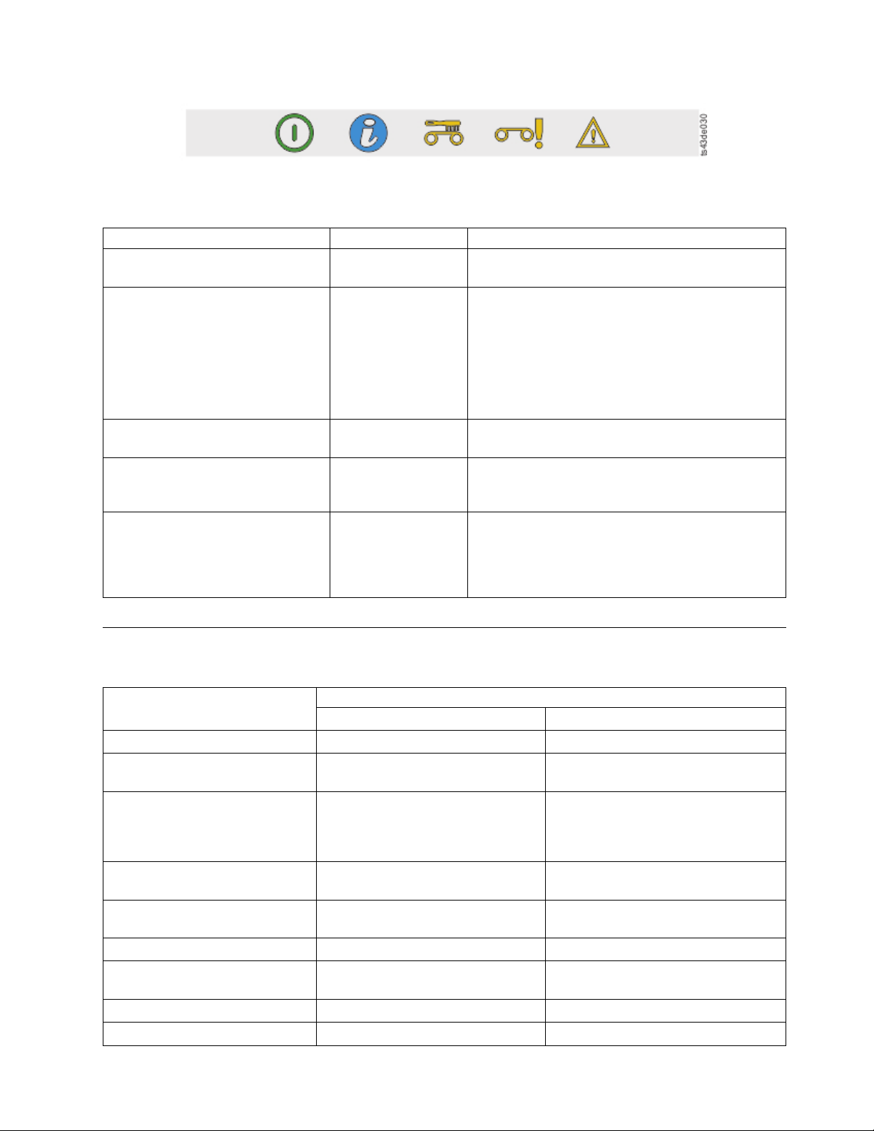
Figure 57. Front panel LEDs
Table 30. Front panel LEDs
LEDs Color Descriptions
Ready Green Steady when power is on, flashing with tape Ready
drive or library robotic activity.
Unit ID Blue when activated The unit identification (UID) LEDs are controlled by
the user through the Maintenance > UID LED
Control screen. The UIDs on the Operator Panel and
base module back panel are activated and
deactivated together. In addition, UIDs on drives and
expansion module back panels can be activated
separately. The UIDs are helpful for locating
components of the library in a data center.
Clean Amber On, when a tape drive-cleaning operation is
recommended.
Attention Amber Flashing if the library detected a condition for which
user attention is necessary, but the library can still
complete most operations.
Error Amber On, if an unrecoverable tape drive or library error
occurs. A corresponding error message is displayed
on the LCD screen. User intervention is required as
the library is not capable of completing some
operations.
Locating Management functions
Table 31. Locating Management functions
Menu Navigation
Task
Advanced settings Not available with this interface Settings > Library > Advanced
Auto Calibration Not available with this interface Settings > Library > Auto Calibration
Auto Clean Not available with this interface Library > Logical Libraries > Actions >
Cartridge, eject from a drive Operation > Move Cartridge from
Drive to Home Slot
Cartridge Inventory, rescan Not available with this interface Cartridges > Actions > Inventory
Cartridges, list Not available with this interface Cartridges
Cartridges, move Not available with this interface Cartridges > Actions > Move
Cartridges, graphical view Not available with this interface Cartridges > Actions > Graphical View
Certificates, create, backup, restore Not available with this interface Settings > Security > GUI
Operator Panel Management GUI
(service user)
Manage Logical Library (Expert Mode)
See “Methods of cleaning drives” on
page 69.
Drives > Actions > Eject Cartridge
from Drive
Library
Cartridges
Managing 63
Page 86
Table 31. Locating Management functions (continued)
Menu Navigation
Task
Cleaning, tape drive Not available with this interface Drives > Actions > Clean Drive See
Configuration, save and restore Not available with this interface Settings > Library > Advanced
Configuration, reset Not available with this interface Settings > Library > Advanced
Configuration file, restore Not available with this interface Settings > Library > Advanced
Configuration file, save Not available with this interface Settings > Library > Advanced
Date and time, configure Configuration > Date & Time Settings > Library > Date and Time
Diagnostics, run Demo Mode Maintenance > Library Tests Library > Actions > Tests
Diagnostics, run Library Verify Not available with this interface Library > Actions > Tests
Diagnostics, run Drive test Maintenance > Library Tests Library > Actions > Tests
Diagnostics, run Slot to Slot
exerciser
Drive firmware, update Maintenance > Drive Firmware
Drives and Modules, reset the list Not available with this interface Settings > Library > Advanced
Drive status Status > Drive Drives
Drive logs, export Maintenance > Drive Logs
Drive, modify port settings Not available with this interface Drives > Actions
Email Notification Not available with this interface Settings > Notifications
Encryption, configure Not available with this interface Settings > Security > Encryption For
Encryption Connectivity Check Not available with this interface Settings > Security > Encryption
Factory/Manufacturing reset Configuration > Reset > Full Factory
Identifier light, turn On or Off Not available with this interface Library > Actions > Turn Identifier
Initial Setup Configuration > Initial System
Inventory List Not available with this interface Cartridges
I/O Station, enable or disable Not available with this interface Library > Modules and Magazines >
I/O Station, open See “Accessing cartridges” on page
Kerberos Authentication, configure Not available with this interface Settings > Security > Kerberos
LCD Adjustment Maintenance > LCD Adjustment Not available with this interface
Not available with this interface Library > Actions > Tests
Upgrade (requires FAT32 format USB
drive)
Download (requires FAT32 format
USB drive)
Reset
Setup
70.
Operator Panel Management GUI
“Methods of cleaning drives” on page
69.
Drive > Actions > Update Drive
Firmware
Drives > Actions
LME, see “Configuring Library
Managed Encryption (KMIP)” on page
70.
Settings > Library > Advanced
Light On or Off
Settings > Library > Initial
Configuration Wizard
Actions > Enable or Disable I/O
Station
Library > Modules and Magazines >
Actions > Unlock I/O Station
Authentication
64 Dell EMC ML3 Tape Library: User's Guide
Page 87

Table 31. Locating Management functions (continued)
Menu Navigation
Task
Operator Panel Management GUI
LDAP Authentication, configure Not available with this interface Settings > Security > LDAP
Authentication
Library firmware, update Maintenance > Library Firmware
Upgrade (requires FAT32 format USB
Library > Actions > Update Library
Firmware
drive)
Library logs, export Maintenance > Library Logs
Download (requires FAT32 format
Library > Actions > Export Library
Logs
USB drive)
Library logs, view or clear Maintenance > View Event Ticket
Library > Events > Actions
Logs
Library Information Status Library > Actions
Library Managed Encryption
(KMIP), configure
Not available with this interface Settings > Security > Encryption For
LME, see “Configuring Library
Managed Encryption (KMIP)” on page
70.
Library Verify, run Maintenance > Library Tests Library > Actions > Tests > Library
Verify
List of Known Drives and
Not available with this interface Settings > Library > Advanced
Modules, reset
Logical Libraries, graphical view Not available with this interface Library > Logical Libraries > Actions >
Graphical View
Logical Libraries, Manage (Basic
Mode)
Logical Libraries, Manage (Expert
Mode)
Magazines, open See “Accessing cartridges” on page
Not available with this interface Library > Logical Libraries > Actions >
Manage Logical Library (Basic Mode)
Not available with this interface Library > Logical Libraries > Actions >
Manage Logical Library (Expert Mode)
Library > Modules and Magazine >
70.
Actions > Unlock Magazine
Network settings Configuration > Network Settings Settings > Network > Ethernet
Notifications, configure Not available with this interface Settings > Notifications
Operator Panel, session lock
Not available with this interface Settings > Security > GUI
timeout
Password Policy Not available with this interface Settings > Security > Password Policy
Path Failover license key, add or
Not available with this interface Settings > Library > Licensed Features
delete
Port Settings, modify Not available with this interface Drives > Actions > Modify Port
Settings
Remote Logging (rsyslog),
configure
Not available with this interface Settings > Notifications > Remote
Logging (rsyslog)
Reset, rediscover devices Not available with this interface Settings > Library > Advanced
Reset Internal IP Range Configuration > Reset > Reset
Not available with this interface
Internal IP Range
Reset Library Not available with this interface Library > Actions > Reset Library
Reset Drive Not available with this interface Drives > Actions > Reset Drive
SNMP, configure Not available with this interface Settings > Notifications > SNMP
Managing 65
Page 88
Table 31. Locating Management functions (continued)
Menu Navigation
Task
SNTP (Simple Network Time
Protocol) Synchronization,
configure
SSH, enable or disable Maintenance > SSH (Secure Shell) Not available with this interface
SSL, enable or disable Not available with this interface Settings > Security > GUI > Secure
Session Timeout Not available with this Interface Settings > Security > GUI > Session
Time Zone, set Not available with this interface Settings > Library > Date and Time >
Unlabeled Media, allow Not available with this interface Settings > Library > Advanced
Users, Access recovery Configuration > User Accounts Not available with this interface
Users, Modify User Passwords Not available with this interface Access > Actions > Modify User
Users, Modify Role Permissions Not available with this interface Access > Actions > Modify Role
Users, Modify Operator Panel PIN Configuration > User Accounts Access > Actions > Modify Operator
Users, Add Not available with this interface Access > Add User
Users, Remove Not available with this interface Access > Actions
Not available with this interface Settings > Library > Date and Time >
Operator Panel Management GUI
SNTP (Simple Network Time Protocol)
Synchronization
Communication
Timeout
Time Zone
Passwords
Permissions
Panel PIN
Default settings
Table 32. Default settings
Parameter Default
User Accounts
“User” Monitor User = monitor
Management GUI Password = null
“User” SuperUser User = superuser
Management GUI Password = sup001
Administrator login User = administrator
Management GUI Password = adm001
Service Login User = service
Management GUI Password = ser001
Local user accounts Local Default Users = monitor, superuser, administrator,
and service
Number of Custom User = 0
User Account Settings
Configuration
Reset Default
Settings
NOT reset
NOT reset
NOT reset
NOT reset
x
66 Dell EMC ML3 Tape Library: User's Guide
Page 89

Table 32. Default settings (continued)
Configuration
Reset Default
Parameter Default
Password rules Min. number of characters
Min. number of uppercase alphabetic characters
Min. number of lowercase alphabetic characters
Min. number of numeric characters
Min. number of special characters
Max. number of identical consecutive characters
Max. number of failed logins
Max. number of days before PW must be changed
Number of PW changes before it can be used again
Management GUI Restricted
Disabled x
8
1
1
1
0
2
3
90
3
Settings
x
Login
Allow I/O Station/Magazine
Disabled x
access by "user" monitor account
Session Locking Disabled x
Remote Authentication (LDAP)
Disabled NOT reset
Configuration
Network configuration (eth0)
Host name Blank NOT reset
IP address (dhcp) NOT reset
Subnet mask (dhcp) NOT reset
Default gateway (dhcp) NOT reset
Auto Negotiate Enabled NOT reset
Speed Auto NOT reset
IPv4 Enabled NOT reset
DHCPv4 Enabled NOT reset
IPv6 NOT reset
IPv6 Prefix Enabled NOT reset
Static v6 Disabled NOT reset
IPv6 Method Disabled NOT reset
DHCPv6 Disabled NOT reset
DNS1 and DNS2 Configuration
(dhcp) NOT reset
for IPv4
DNS1 and DNS2 Configuration
Disabled NOT reset
for IPv6
Network Access Services
Primary Network Interface (eth0) Enabled NOT reset
Secondary Network Interface
Disabled NOT reset
(eth1)
SSH Disabled NOT reset
HTTPS Disabled NOT reset
Self Signed SSL Certificate No file NOT reset
Internal IP (eth2)
Internal network IP IP Range defined with Operator Panel NOT reset
Managing 67
Page 90
Table 32. Default settings (continued)
Configuration
Reset Default
Parameter Default
I/O Station/Magazine
I/O Station Enabled x
I/O Station/Magazines Allow
Monitor "User" access
Logical Libraries Disabled (one underlying logical library) All deleted leaving
NTP/SNTP Setting Disabled NOT reset
Date Blank or existing NOT reset
Time Blank or existing NOT reset
Time Zone GMT NOT reset
Email Notifications (SMTP) Disabled x
SNMP
SNMP v1, v2 Disabled x
Licensed Features (need license key for enablement)
Path Failover Disabled NOT reset
SCSI Defaults
Product Name - Marketing
Name
Library Product ID - INQUIRY
Product ID String
Library Vendor ID - INQUIRY
Vendor ID String
SCSI element addressing Starting element addresses
Disabled x
ML3 x
3573-TL x
Dell x
in decimal:
Slot = 1001
Drives = 1
I/E Elements = 101
Settings
a single logical
library
x
Values in hex are:
Slot = 0x3E9
Drives = 0x1
I/E Elements = 0x65
Miscellaneous settings
Barcode format returned to host Align left x
Barcode length returned to host Eight leftmost characters x
Language settings English NOT reset
Auto Clean Disabled x
Media Barcode Compatibility
Check
Empty Slot/Unlabeled Cartridge
Detection
Management GUI Timeout 30 minutes x
Drive Defaults
Enabled x
Enabled x
68 Dell EMC ML3 Tape Library: User's Guide
Page 91

Table 32. Default settings (continued)
Configuration
Reset Default
Parameter Default
Drive speed and topology
settings
Odometer Enabled NOT reset
Automatic/Automatic x
Settings
Methods of cleaning drives
Automatic cleaning of tape drives is disabled by default in the library. However, automatic cleaning of
tape drives is recommended for this library. It is also possible to initiate manual or host cleaning
methods.
The head of every tape drive in the tape library must be kept clean to prevent errors that are caused by
contamination. To help you keep the drives clean, Dell provides a cleaning cartridge with the library. The
library uses the cleaning cartridge to clean the drive with whatever cleaning method that you choose. In
all methods, cleaning is done after the data cartridge is unloaded from the drive and before the next load.
It is the operator’s responsibility to monitor cleaning cartridge usage and replace cleaning cartridges as
necessary. This tape library provides multiple ways to monitor and manage cleaning cartridges. If SNMP
traps are enabled, a trap is generated when a cleaning cartridge expires. It is also possible to use the
Management GUI to monitor the cleaning cycles that remain on a cleaning cartridge and to the enable a
setting that automatically ejects expired cleaning cartridges.
Three methods of cleaning are available.
Automatic cleaning
Automatic cleaning enables the library to automatically respond to any tape drive's request for
cleaning and to begin the cleaning process. The cleaning process is transparent to any host
application that uses the library.
Select Auto Clean to enable the auto cleaning feature. When enabled, the library automatically
initiates a cleaning operation when media is unloaded from a drive that requires cleaning instead
of creating a warning event when a drive requires cleaning. For reliable operation, enable Auto
Clean for each logical library and ensure that the library has a valid cleaning cartridge.
When a cleaning operation is initiated, the library first attempts to use an unexpired cleaning
cartridge from the same logical library as the tape drive. If the logical library does not contain an
unexpired cleaning cartridge, the library attempts to use an unexpired cleaning cartridge from a
storage slot that is not assigned to a logical library. The library does not use a cleaning cartridge
from a different logical library. When auto cleaning is enabled, ensure that each logical library has
an unexpired cleaning cartridge. Or, place at least one unexpired cleaning cartridge in a storage
slot that is not assigned to a logical library.
After the initial configuration, Auto Clean can be turned on or off by accessing the Logical
Library Wizard Expert Mode.
1. Go to Library > Logical Libraries > Actions > Manage Logical Library (Expert Mode).
2. Select the logical library, then click Edit.
3. Click Next to go to the General Settings screen.
4. Check or clear Auto Clean, then click Next on the subsequent screens.
5. If a change was made, click Finish and the Logical Libraries are reconfigured. If no changes
were made, click Cancel.
Managing 69
Page 92

Note: Dell recommends enabling the Auto Clean function on the library. With the Auto Clean
function enabled, drive cleaning occurs automatically. The only time Auto Cleaning must be
disabled is when your backup application requires that it has control.
Manual cleaning
Manual cleaning requires that you select a menu option from the Management GUI to clean one
or more of the tape drives. Manual cleaning is always supported.
Host cleaning
Host cleaning enables the backup application to define and control the cleaning process.
Automatic and manual cleaning use the CLNxxx VOLSER.
Note: For tape cartridge information, see “Supported tape cartridges” on page 16.
Accessing cartridges
Each magazine has a button that provides an easy way to open a magazine. See “Front panel” on page 7.
Each module can be configured to have a portion of the right magazine that is designated as an I/O
station or this option can be disabled. To open the I/O station, press the magazine button for less than 3
seconds. To open the entire magazine, press the magazine button for more than 3 seconds.
Notes:
1. If a magazine is opened, no other magazines or I/O stations can be opened.
2. If during the magazine open process the magazine is not opened within 30 seconds, the magazine
locks.
3. The user must pull out the magazine, as the magazine does not eject.
The LED also provides an indicator of the current state of that magazine.
Table 33. Magazine state
Magazine state LED state Description
Closed Steady ON I/O station is enabled.
Closed Slow Flash Magazine open is in process.
Closed Fast Flash Magazine is opened.
Closed OFF I/O station is not enabled.
Opened OFF Magazine is opened.
Configuring Library Managed Encryption (KMIP)
With the Key Management Interoperability Protocol (KMIP) Wizard, you can configure the use of KMIP
key management servers with the library. Access the wizard from the Actions menu with the Manage
Encryption option. The Library Managed Encryption Licensed Feature is already activated on your
library, and cannot be deactivated. However, the feature must be configured before LME can be used.
Note: Before you run the Encryption Wizard
v Confirm that the Library Managed Encryption (KMIP) license is activated on the Settings > Library >
Licensed Features page.
v Verify that the KMIP server is available on the network and is configured for use with this library. For
information on configuring KMIP servers for use with the library, see the KMIP server documentation.
Note: If you plan to use the IBM Security Key Lifecycle Manager (SKLM), go to “Related Publications”
on page xxi for information on setup and configuration.
70 Dell EMC ML3 Tape Library: User's Guide
Page 93

KMIP Wizard configuration
1. In the Actions menu, click Manage Encryption to start the wizard.
2. The Wizard Information screen displays information about the wizard. On this screen, it is also
possible to clear all the settings that can be done in the wizard. If the library configuration is complete
and the KMIP server is available on the network, click Next.
3. The Certificate Option screen displays the different certificate options that can be used to establish a
secure communication to the KMIP server. You can select from the following options:
v Library Self-Signed Certificate (default option) - A self-signed certificate that is generated by the
library is used.
v Uploaded Certificate - Upload a PCKS #12 file that includes a certificate and corresponding key.
v Generate Certificate Request (CSR) - A CSR is generated by the library that must be signed by a
CA server. This method requires a CA certificate that must be provided during the wizard steps.
a. Certification Configuration
– Library Self-Signed Certificate – skip to the next step.
– Uploaded Certificate
1) Upload the PKCS #12 file in the certificate area on the Certificate Option screen.
2) If this file requires a password, it must be provided in the Certificate Password input
field. If no password, the field can be left empty.
3) After successfully upload of the certificate, click Next.
– Generate Certificate Request (CSR)
1) The Certificate Authority Information screen displays prerequisites for using the KMIP
certificate. When the prerequisites are met, click Next.
2) The Certificate Authority Certificate Entry screen displays instructions for obtaining the
CA certificate for the KMIP server. Follow the instructions to copy the CA certificate from
the management console. Paste the CA certificate into the wizard and then click Next.
3) The Library Certificate Information screen displays information about the next wizard
steps. Click Next.
b. The KMIP Client Configuration screen provides options for two types of server authentication.
– If your KMIP server uses a client user name and password for authentication, enter the user
name and password that were specified on the KMIP management console for the library.
– If your KMIP server uses only certificate validation for authentication, select Enable KMIP
Certificate only authentication. Select this option only if you are using a KMIP server that
does not support a client user name and password. This default method is used when KMIP
is used with the IBM Security Key Lifecycle Manager.
1) In the KMIP Server Configuration screen, enter the IP address or fully qualified host
name and port number for up to ten KMIP servers.
2) To verify access to the KMIP servers, click Connectivity Check.
3) Check at the KMIP server side that the server accepts the certificate of the library.
4) The Setup Summary screen displays the settings that are collected by the wizard. Verify
that the settings are correct and that no errors are in the Done column.
- If you need to modify any settings or fix any issues, either click Back to reach the
applicable screen or Cancel to leave the wizard to fix the issues and return later.
- If the settings are correct and no errors are reported, click Finish.
Once the wizard finishes, the Library Managed Encryption (KMIP) encryption mode is selectable in the
Logical Library Wizard (Expert Mode) on the Library > Logical Libraries page.
Managing 71
Page 94

72 Dell EMC ML3 Tape Library: User's Guide
Page 95

Troubleshooting
Attention: This library is designed to operate when installed in a rack with the rack rail kit or on a
tabletop. Operating the library without installing it correctly in the rails might cause errors. Placing any
weight on top of the library might also cause errors. Expanded library configurations on tabletops are not
supported.
Finding event information
You can find event information by viewing log files from the Library > Events screen or downloading
support tickets from the Drives > Actions > Export Drive Logs screen.
See “Locating Management functions” on page 63.
Identifying a failed component
1. Management GUI: Activate the UID LEDs from the Library > Actions > Turn Identifier Light On or
Off screen. This action illuminates the blue LED on the front and rear of the Base Module to identify
the library that contains the failed module or component.
2. Identify the module within the library that contains the failed component.
a. In the upper left of the Home screen, locate the module that indicates an error.
b. Click or tap the module for information on the failed component.
Running library tests
The library provides tests to verify library operations.
v On the Management GUI, go to Library > Actions > Tests and choose the library test that you want to
run.
– Library Verify
– Demo Mode
– Drive Test
– Slot to Slot Exerciser
v On the Operator Panel, go to Maintenance > Library Tests to run tests from the Operator Panel.
– Demo Mode
– Drive Diagnostics
Troubleshooting Guide
Refer to this table of symptoms or errors that might occur with the tape library and the installed tape
drives. The table provides actions to correct the problems. See www.Dell.com/support.
Table 34. Resolving errors
Problem Solution
Event code/Attention information on Management GUI or Library
Event code that is shown on
Event Ticket on the
Management GUI. See “Finding
event information.”
v Look up the error code. See Event Codes.
v Try to resolve the failure.
v If necessary, power cycle the library.
73
Page 96
Table 34. Resolving errors (continued)
Problem Solution
Failure/Attention Indication on
Operator Panel display.
Attention LED is lit on the front
or the rear of the Base Module.
Failure/Attention Indication on
Management GUI Library
Dashboard
Attention LED and Cleaning
LED are lit.
Single Character Display (SCD)
is shown on drive.
The Attention LED is lit but the
Cleaning LED is not lit after a
cartridge load.
The Cleaning LED is lit after a
cleaning cartridge was used.
A particular cartridge sets off
the Attention LED and possibly
the Cleaning LED.
Host receives error message.
SNMP Monitoring system
receives trap.
Event is received by email
notification.
Review tickets on the Check Event Ticket Log on Management GUI.
Review tickets on the Check Event Ticket Log on Management GUI.
Tap the icon to see information about the event.
This problem is likely caused by a drive that requires cleaning.
v Check Event Ticket Log on Management GUI.
1. Review tickets on the Check Event Ticket Log on Management GUI.
2. Use SCD. See Drive Single Character Display.
The library was unable to complete the requested operation with the selected tape
cartridge.
v Use cartridges that are compatible with the drive type.
v Use the correct type of cartridges for the operation. For example, use a cleaning
cartridge for cleaning.
v Make sure that you are using a Universal cleaning cartridge.
The cleaning cartridge is expired. (A cleaning cartridge expires after 50 cleaning
cycles.)
v Replace the cleaning cartridge.
Retry the operation with a different cartridge.
If the Attention LED is cleared, and then immediately redisplays each time that a
particular cartridge is reloaded, that cartridge must be suspected as defective.
v Export the cartridge and load a known good cartridge. In some cases, a
cartridge can be worn out, the memory is defective, or was formatted as a
Firmware Upgrade cartridge.
v Any cartridge that is suspected of being defective or contaminated must NOT
be reused in any drive.
v If the bad cartridge is a cleaning cartridge, it might be expired.
Event Notification on Host, SNMP, or Email
v Use ITDT. See “The ITDT firmware update, dump retrieval and drive test tool ”
on page 77.
v Use Sense Data. See “Sense data” on page 100.
Check Event Ticket Log on Management GUI.
Check Event Ticket Log on Management GUI.
Cartridge Movement Problems
74 Dell EMC ML3 Tape Library: User's Guide
Page 97

Table 34. Resolving errors (continued)
Problem Solution
Tape is stuck in drive. Try the following steps, in this order, to remove the stuck tape.
Note: The tape drive must rewind the tape before it is ejected. This procedure can
take up to ten minutes or more, depending on how much tape must be rewound.
When the tape is rewound, the eject cycle takes fewer than 16 seconds.
The Ready light flashes while the tape rewinds. Wait for the tape to finish
rewinding before another operation is attempted.
1. Stop all Host Activity.
2. Attempt to unload or move the cartridge to a slot.
3. Power down the library, disconnect the cable from the drive, power on the
library, and wait until the tape drive is idle or ready. Attempt to Move
Cartridge to Slot.
4. Attempt a Eject Cartridge from Drive as an emergency unload operation.
Important: Inspect the tape cartridge that was stuck. Damage or misplaced labels
on the cartridge might cause the load/unload failure. Discard any tape cartridge
that is found to have issues.
Cartridge cannot be removed
from storage slot.
1. Unlock the magazine and extend it to access the storage slot.
2. Grasp the cartridge and remove it from the storage slot. Some tapes need to be
inserted and removed several times to condition them for free movement in
and out of the magazine.
3. Check the bar code label and verity that it is secure to the cartridge.
4. Check the cartridge for damage.
Other Library Problems
Device does not power on.
v Check all power cord connections.
v Check the LEDs on the power supplies.
v Make sure that Power on the front panel was pressed, and the green Ready
LED is lit.
v Make sure that the outlet has power. Try another working outlet.
v Replace the power cord.
No message appears on the
Operator Panel display.
v Check all power cord connections.
v Check the LEDs on the power supplies.
v Make sure that Power on the front panel was pressed, and the green Ready
LED is lit.
v Make sure that the outlet has power. Try another working outlet.
Cannot load the cleaning
cartridge.
v Make sure that you are using an LTO cleaning cartridge.
v Make sure that the cleaning cartridge is not expired. A cleaning cartridge
expires after 50 cleaning cycles.
User account locked. From the Configuration > User Accounts > Access Recovery page, you can
receive a temporary administrator password for login to the Management GUI
that is valid for two hours.
Tape Drive or Media Problems
A cartridge that is recently
imported from a different
environment is causing issues.
Media that is moved from one environment to another can cause issues until it
acclimates to the new conditions. A cartridge must be acclimated for at least 24
hours before it is used, particularly if it was stored at a substantially different
temperature or level of humidity than the device.
The library displays incorrect
bar codes.
v Verify that the label is properly applied.
v Verify that the label is not soiled.
Troubleshooting 75
Page 98

Table 34. Resolving errors (continued)
Problem Solution
Cleaning or data cartridge
incompatible with drive.
Fibre Channel connection
problems
SAS connection problems Check Drive Status screen to check the connection for your tape drive.
Cannot connect to the
Management GUI.
Cannot connect to Key
Management Server for LME.
v Check the event log to see which cartridge is incompatible.
v Make sure that you are using data and cleaning cartridges that are compatible
with the drive and model of your device.
v Make sure that you are using the correct cartridge type for the operation. The
device automatically unloads incompatible cartridges,and the Attention LED
flashes.
v Export the media.
Connection Problems
Check Drive Status screen to check the link connection for your tape drive.
v Check that the Fibre Channel speed is set to either match the HBA/switch
speed or set to Automatic
v Verify that cables are not damaged.
v Verify that cables are securely connected on both ends.
v Verify Host Connectivity.
v Use ITDT to debug the problem.
v Verify that cables are not damaged.
v Verify that cables are securely connected on both ends.
v Verify Host Connectivity.
v Use ITDT to debug the problem.
v Verify that the Ethernet cable is connected to the Base Module’s controller card
and to the LAN.
v Verify that the link LED on the RJ45 (LAN) connector is lit when the device is
turned on. If the LED is not lit, the device is not communicating with the LAN.
See your network administrator for help.
v Verify that the device is configured with a valid static network address or
DHCP is enabled so the device can obtain a network address. If DHCP is used,
write down the device's network address from the Operator Panel login screen.
If a valid DHCP address is not available, the library is not communicating with
the DHCP server. See your network administrator for help.
v Enter the library’s IP address into the address bar of a web browser that is
connected to the same LAN as the device. If the Management GUI page does
not display, ping the device's IP address. If the ping fails, check that no
firewalls or other obstructions to network traffic exist between the computer
with the web browser and the device. See your network administrator for help.
Run the Encryption Connectivity Check. See “Locating Management functions” on
page 63.
Pre-call checklist
If you have questions or problems with the library, complete these steps before a call to technical support
is placed.
Note: Where instructions refer you to the web, go to www.Dell.com/support.
1. Verify that you exhausted all troubleshooting options. See “Troubleshooting Guide” on page 73.
2. Collect library and drive logs. See “Locating Management functions” on page 63.
3. Verify that the library and drive firmware is at the most recent level. See “Locating Management
functions” on page 63.
76 Dell EMC ML3 Tape Library: User's Guide
Page 99

4. Verify that your device drivers are at the most recent level.
v For the current release of device drivers, see Supported Device Drivers.
v For the current release of device drivers by independent software vendors (ISVs), go to the
appropriate third-party website.
5. Verify whether your hardware and software configuration is supported. See “Host connectivity” on
page 20.
6. Complete a general checkup of the hardware and connections:
v Ensure that the host interface cable connector does not contain bent or recessed pins.
v Ensure that all retention screws for the host interface cable and terminator are securely tightened.
v Verify the host connection. See “Verifying the host connection” on page 58.
If you still have a problem after these steps are completed, see “Contacting Dell” on page xii.
Contacting Dell
For customers in the United States, call 800-WWW-DELL (800-999-3355).
Note: If you do not have an active Internet connection, you can find contact information about your
purchase invoice, packing slip, bill, or Dell product catalog.
Dell provides online and telephone-based support and service options. Service availability varies by
country and product, and some services might not be available in your area. To contact Dell for sales,
technical support, or customer service issues follow the steps that are listed:
1. Go to www.Dell.com/support.
2. Select your country from the drop-down menu on the lower right corner of the page.
3. For customized support:
a. Enter your system Service Tag in the Enter your Service Tag field.
b. Click Submit. The support page that lists the various support categories is displayed.
4. For general support:
a. Select your product category.
b. Select your product segment.
c. Select your product. The support page that lists the various support categories is displayed.
5. For contact details of Dell Global Technical Support:
a. Click Global Technical Support.
b. The Contact Technical Support page is displayed with details to call, chat, or e-mail the Dell
Global Technical Support team.
Diagnostic information
The ITDT firmware update, dump retrieval and drive test tool
ITDT has multiple functional capabilities and is a quick, convenient, and efficient method for drive
firmware updates. As a note, drive memory dump retrievals are completed by the tool as well.
The ITDT tool:
v Runs quick or extended diagnostic tests on tape drives. If the library is online to the server/host where
the tool resides, ITDT communicates with the drive through the library to load and unload a test
cartridge, exercising some library functions.
v Retrieves firmware memory dumps from tape drives and libraries.
v Completes a firmware update on tape drives or libraries. See note about library firmware update.
Troubleshooting 77
Page 100

v Tests the performance of the environment by completely writing a cartridge and measuring
performance.
v Retrieves and displays cartridge information.
v Verifies the encryption environment.
v Does not require special device drivers.
v Is available for most major platforms.
Note: Be sure that you have the most current version of ITDT if you are updating firmware on a recent
drive type. Before ITDT is used, verify that your library host operating system is at the current released
level. This action ensures optimum read/write operations for diagnostic tests.
Event codes
Event Reporting System
Events are used in the library Ticket, and Event system to store all types of events with a unique event
code and event description. These event codes are shown on the user interfaces as the resulting code for
any type of event at the highest level of information. No internal error code is shown at this level.
Events are sent by the library to different recipients like SNMP targets or email notification. These events
have a common structure and unique codes for every type of event.
The event code system is used for the following events:
v Error event
v Warning event
v Configuration event
v Informational event
Event code structure
Example event code
Event: 2057 - Robotics shipping lock in incorrect position
The event log with the library also includes a date and time stamp for each event. Press the associated
time stamp to see the event code and a description of the event. The date and time format can be
changed in the Date/Time Format section in the Management GUI.
v mm.dd.yyyy
v dd.mm.yyyy
v yyyy.mm.dd
The time format can be set for 12 hours or 24 hours.
v 12 hour: hh.mm.ss am/pm
v 24 hour: hh.mm.ss
Where
v yyyy is the year.
v mm is the month.
v dd is the current day.
v hh is hours.
v mm is minutes.
v ss is seconds.
78 Dell EMC ML3 Tape Library: User's Guide
 Loading...