

Page 1
Dell™ Dimension™ C521
Owner’s Manual
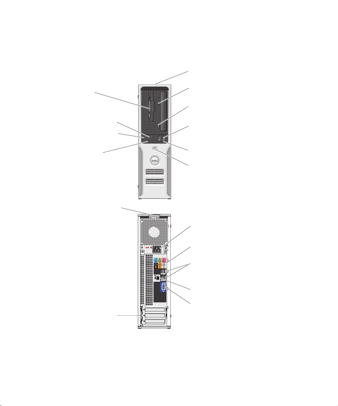
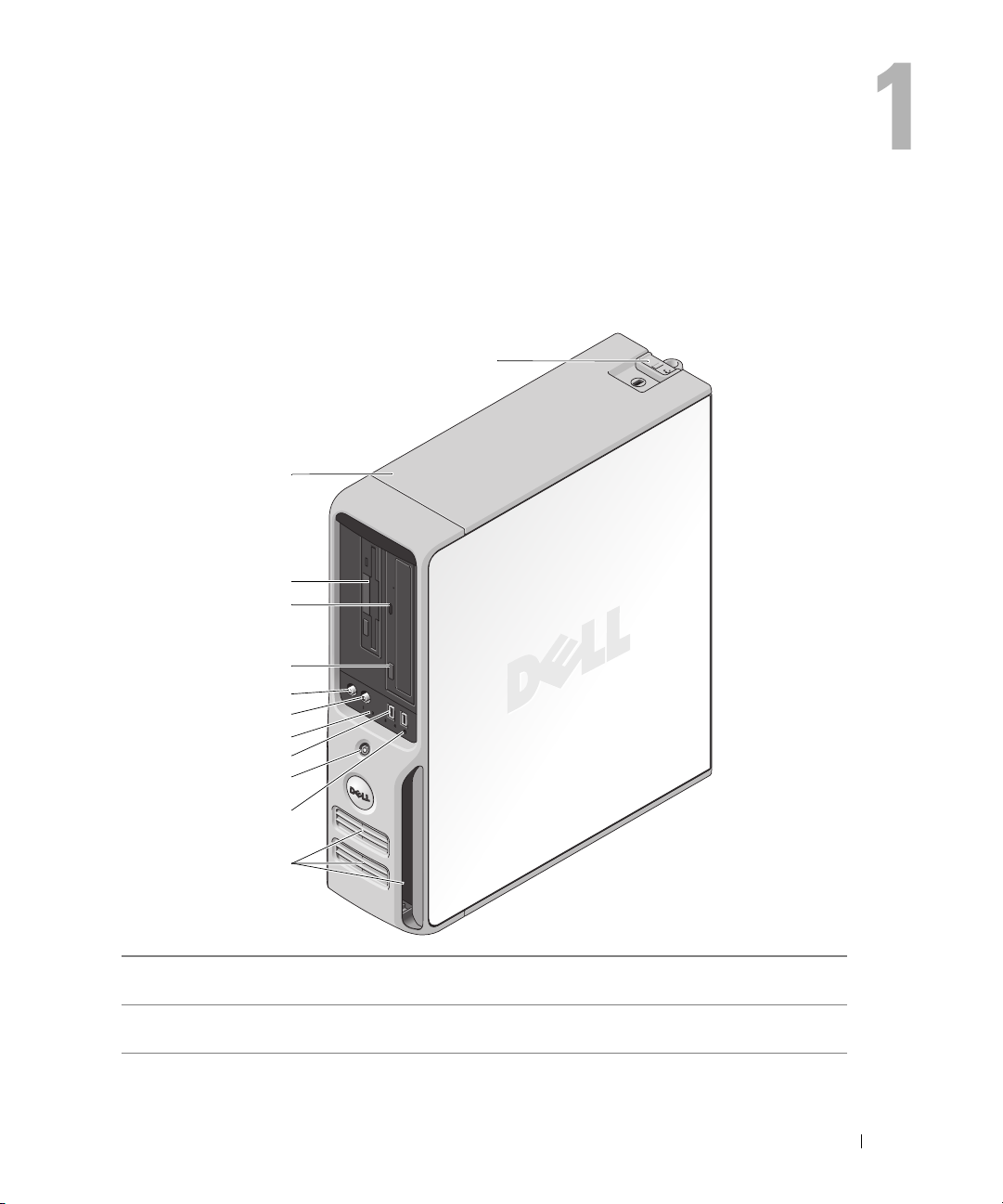
FlexBay for optional
floppy drive or Media
Card Reader
Service Tag
CD or DVD activity light
CD or DVD eject button
headphone connector
microphone connector
diagnostic lights
cover release latch
card slots for
PCI (1),
PCI Express x1 (1)
PCI Express x16 (1)
USB 2.0 connectors (2)
hard drive activity light
power button
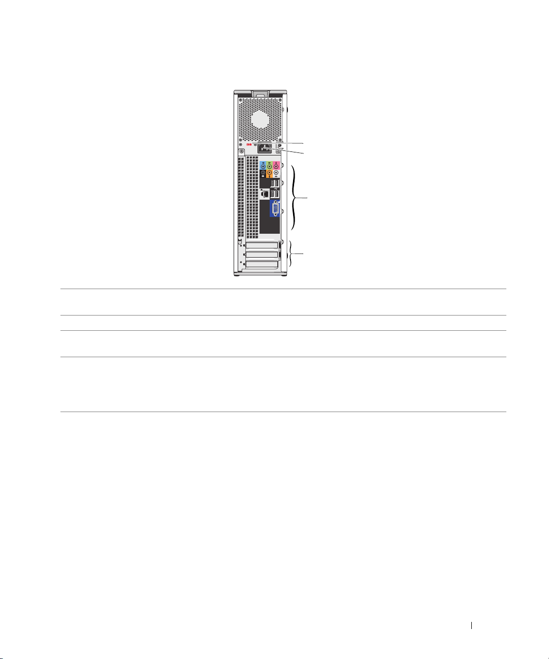
power connector
audio connectors
USB 2.0 connectors (4)
network adapter
VGA video connector (integrated)
Model DCNE
www.dell.com | support.dell.com
Page 2

Notes, Notices, and Cautions
NOTE: A NOTE indicates important information that helps you make better use of your computer.
NOTICE: A NOTICE indicates either potential damage to hardware or loss of data and tells you how to avoid the
problem.
CAUTION: A CAUTION indicates a potential for property damage, personal injury, or death.
Abbreviations and Acronyms
For a complete list of abbreviations and acronyms, see the "Glossary" on page 127.
If you purchased a Dell™ n Series computer, any references in this document to Microsoft
operating systems are not applicable.
®
Windows®
____________________
Information in this document is subject to change without notice.
© 2006 Dell Inc. All rights reserved.
Reproduction in any manner whatsoever without the written permission of Dell Inc. is strictly forbidden.
Trademarks used in this text: Dell, the DELL logo, Inspiron, Dell Precision, Dimension, OptiPlex, Latitude, PowerEdge, PowerConnect,
PowerVault, PowerApp, XPS, Dell TravelLite, and Dell OpenManage are trademarks of Dell Inc.; Microsoft and Windows are registered
trademarks of Microsoft Corporation. AMD, AMD Athlon, and combinations thereof, and Cool ’n’ Quiet are trademarks of Advanced Micro
Devices, Inc; EMC is a registered trademark of EMC Corporation.
Other trademarks and trade names may be used in this document to refer to either the entities claiming the marks and names or their products.
Dell Inc. disclaims any proprietary interest in trademarks and trade names other than its own.
Model DCNE
August 2006 P/N RP333 Rev. A00
Page 3

Contents
Finding Information . . . . . . . . . . . . . . . . . . . . . . . . . . . . . . . . 9
1 Setting Up and Using Your Computer . . . . . . . . . . . . . . . . 13
Front View of the Computer . . . . . . . . . . . . . . . . . . . . . . . . . . . 13
Back View of the Computer
Back Panel I/O Connectors
Setting Up a Printer
Printer Cable
. . . . . . . . . . . . . . . . . . . . . . . . . . . . . . . . 17
Connecting a USB Printer
Connecting to the Internet
. . . . . . . . . . . . . . . . . . . . . . . . . . . 15
. . . . . . . . . . . . . . . . . . . . . . . . . . . 16
. . . . . . . . . . . . . . . . . . . . . . . . . . . . . . . 17
. . . . . . . . . . . . . . . . . . . . . . . . . . 18
. . . . . . . . . . . . . . . . . . . . . . . . . . . . 18
Setting Up Your Internet Connection
Playing CDs and DVDs
Adjusting the Volume
Adjusting the Picture
Copying CDs and DVDs
How to Copy a CD or DVD
Using Blank CDs and DVDs
Helpful Tips
. . . . . . . . . . . . . . . . . . . . . . . . . . . . . . 20
. . . . . . . . . . . . . . . . . . . . . . . . . . . . 21
. . . . . . . . . . . . . . . . . . . . . . . . . . . . 22
. . . . . . . . . . . . . . . . . . . . . . . . . . . . . . 22
. . . . . . . . . . . . . . . . . . . . . . . . . . 22
. . . . . . . . . . . . . . . . . . . . . . . . . 23
. . . . . . . . . . . . . . . . . . . . . . . . . . . . . . . . . 23
Using a Media Card Reader (Optional)
Setting Up a Home and Office Network
Network Setup Wizard
Power Management
Standby Mode
Hibernate Mode
. . . . . . . . . . . . . . . . . . . . . . . . . . . 27
. . . . . . . . . . . . . . . . . . . . . . . . . . . . . . . 27
. . . . . . . . . . . . . . . . . . . . . . . . . . . . . . . 27
. . . . . . . . . . . . . . . . . . . . . . . . . . . . . . . 28
. . . . . . . . . . . . . . . . . . . . 19
. . . . . . . . . . . . . . . . . . . . . 24
. . . . . . . . . . . . . . . . . . . . . 26
Power Options Properties
Power Schemes Tab
Advanced Tab
Hibernate Tab
. . . . . . . . . . . . . . . . . . . . . . . . . . . . 28
. . . . . . . . . . . . . . . . . . . . . . . . . . . . 28
. . . . . . . . . . . . . . . . . . . . . . . . . . . . . . . . 29
. . . . . . . . . . . . . . . . . . . . . . . . . . . . . . . . 29
Enabling Cool ’n’ Quiet™ Technology
. . . . . . . . . . . . . . . . . . . . . . 30
Contents 3
Page 4

2 Solving Problems. . . . . . . . . . . . . . . . . . . . . . . . . . . . . . 31
Troubleshooting Tips. . . . . . . . . . . . . . . . . . . . . . . . . . . . . . . 31
Battery Problems
Drive Problems
CD and DVD drive problems
Hard drive problems
E-Mail, Modem, and Internet Problems
Error Messages
Keyboard Problems
Lockups and Software Problems
The computer does not start up
The computer stops responding
A program stops responding
A program crashes repeatedly
. . . . . . . . . . . . . . . . . . . . . . . . . . . . . . . . . 31
. . . . . . . . . . . . . . . . . . . . . . . . . . . . . . . . . . 31
. . . . . . . . . . . . . . . . . . . . . . . . 32
. . . . . . . . . . . . . . . . . . . . . . . . . . . . 33
. . . . . . . . . . . . . . . . . . . . . 33
. . . . . . . . . . . . . . . . . . . . . . . . . . . . . . . . . 34
. . . . . . . . . . . . . . . . . . . . . . . . . . . . . . . 35
. . . . . . . . . . . . . . . . . . . . . . . . 36
. . . . . . . . . . . . . . . . . . . . . . 36
. . . . . . . . . . . . . . . . . . . . . . 36
. . . . . . . . . . . . . . . . . . . . . . . . 36
. . . . . . . . . . . . . . . . . . . . . . . 36
A program is designed for an earlier Windows operating system
A solid blue screen appears
Other software problems
Media Card Reader Problems
Memory Problems
Mouse Problems
. . . . . . . . . . . . . . . . . . . . . . . . . . . . . . . . 38
. . . . . . . . . . . . . . . . . . . . . . . . . . . . . . . . . 39
. . . . . . . . . . . . . . . . . . . . . . . . 37
. . . . . . . . . . . . . . . . . . . . . . . . . . 37
. . . . . . . . . . . . . . . . . . . . . . . . . . 38
. . . . . 37
4 Contents
Network Problems
Power Problems
Printer Problems
Scanner Problems
. . . . . . . . . . . . . . . . . . . . . . . . . . . . . . . . 40
. . . . . . . . . . . . . . . . . . . . . . . . . . . . . . . . . 40
. . . . . . . . . . . . . . . . . . . . . . . . . . . . . . . . . 41
. . . . . . . . . . . . . . . . . . . . . . . . . . . . . . . . 42
Sound and Speaker Problems
No sound from speakers
No sound from headphones
Video and Monitor Problems
The screen is blank
. . . . . . . . . . . . . . . . . . . . . . . . . . . . . 44
The screen is difficult to read
. . . . . . . . . . . . . . . . . . . . . . . . . . 43
. . . . . . . . . . . . . . . . . . . . . . . . . . 43
. . . . . . . . . . . . . . . . . . . . . . . . 44
. . . . . . . . . . . . . . . . . . . . . . . . . . 44
. . . . . . . . . . . . . . . . . . . . . . . . 45
Page 5

3 Advanced Troubleshooting. . . . . . . . . . . . . . . . . . . . . . . 47
Power Light and Diagnostic Lights . . . . . . . . . . . . . . . . . . . . . . . 47
Power Light
Diagnostic Lights
. . . . . . . . . . . . . . . . . . . . . . . . . . . . . . . . . 47
. . . . . . . . . . . . . . . . . . . . . . . . . . . . . . 48
Dell Diagnostics
Dell Diagnostics Main Menu
Drivers
. . . . . . . . . . . . . . . . . . . . . . . . . . . . . . . . . . . . . . 52
What Is a Driver?
Identifying Drivers
Reinstalling Drivers
Resolving Software and Hardware Incompatibilities
Restoring Your Operating System
Using Microsoft
Using Dell™ PC Restore by Symantec
Removing Dell PC Restore
. . . . . . . . . . . . . . . . . . . . . . . . . . . . . . . . . 50
. . . . . . . . . . . . . . . . . . . . . . . . 51
. . . . . . . . . . . . . . . . . . . . . . . . . . . . . . 52
. . . . . . . . . . . . . . . . . . . . . . . . . . . . . 52
. . . . . . . . . . . . . . . . . . . . . . . . . . . . . 53
. . . . . . . . . . . . . 54
. . . . . . . . . . . . . . . . . . . . . . . . 54
®
Windows® XP System Restore . . . . . . . . . . . . . 54
. . . . . . . . . . . . . . . . . . . 56
. . . . . . . . . . . . . . . . . . . . . . . . . 57
4 Removing and Installing Parts. . . . . . . . . . . . . . . . . . . . . 59
Before You Begin. . . . . . . . . . . . . . . . . . . . . . . . . . . . . . . . . 59
Recommended Tools
Turning Off Your Computer
Before Working Inside Your Computer
Removing the Computer Cover
Inside View of Your Computer
. . . . . . . . . . . . . . . . . . . . . . . . . . . . 59
. . . . . . . . . . . . . . . . . . . . . . . . . 59
. . . . . . . . . . . . . . . . . . . 60
. . . . . . . . . . . . . . . . . . . . . . . . . . 60
. . . . . . . . . . . . . . . . . . . . . . . . . . 62
System Board Components
Memory
. . . . . . . . . . . . . . . . . . . . . . . . . . . . . . . . . . . . . . 64
DDR2 Memory Overview
Installing Memory
Removing Memory
Cards
. . . . . . . . . . . . . . . . . . . . . . . . . . . . . . . . . . . . . . . 68
Drives
. . . . . . . . . . . . . . . . . . . . . . . . . . . . . . . . . . . . . . . 75
General Installation Guidelines
Drive Interface Connectors
. . . . . . . . . . . . . . . . . . . . . . . . . . . . 63
. . . . . . . . . . . . . . . . . . . . . . . . . . 64
. . . . . . . . . . . . . . . . . . . . . . . . . . . . . . 65
. . . . . . . . . . . . . . . . . . . . . . . . . . . . . 68
. . . . . . . . . . . . . . . . . . . . . . . 75
. . . . . . . . . . . . . . . . . . . . . . . . . 76
Contents 5
Page 6

Power Cable Connector . . . . . . . . . . . . . . . . . . . . . . . . . . 76
Connecting and Disconnecting Drive Cables
. . . . . . . . . . . . . . . . 76
Hard Drive
Floppy Drive
Media Card Reader
CD/DVD Drive
Battery
Replacing the Computer Cover
. . . . . . . . . . . . . . . . . . . . . . . . . . . . . . . . . . . . 77
Removing a Hard Drive
Installing a Hard Drive
. . . . . . . . . . . . . . . . . . . . . . . . . . . . . . . . . . . 81
Removing a Floppy Drive
Installing a Floppy Drive
Removing a Media Card Reader
Installing a Media Card Reader
. . . . . . . . . . . . . . . . . . . . . . . . . . . . . . . . . . . 86
Removing a CD/DVD Drive
Installing a CD/DVD Drive
. . . . . . . . . . . . . . . . . . . . . . . . . . . . . . . . . . . . . . 89
Replacing the Battery
. . . . . . . . . . . . . . . . . . . . . . . . . . . 77
. . . . . . . . . . . . . . . . . . . . . . . . . . . 78
. . . . . . . . . . . . . . . . . . . . . . . . . . 81
. . . . . . . . . . . . . . . . . . . . . . . . . . 82
. . . . . . . . . . . . . . . . . . . . . . . . . . . . . . . 83
. . . . . . . . . . . . . . . . . . . . . . 84
. . . . . . . . . . . . . . . . . . . . . . . 85
. . . . . . . . . . . . . . . . . . . . . . . . . 87
. . . . . . . . . . . . . . . . . . . . . . . . . . 87
. . . . . . . . . . . . . . . . . . . . . . . . . . . . 89
. . . . . . . . . . . . . . . . . . . . . . . . . 90
5 Appendix . . . . . . . . . . . . . . . . . . . . . . . . . . . . . . . . . . . 93
Specifications . . . . . . . . . . . . . . . . . . . . . . . . . . . . . . . . . . 93
6 Contents
System Setup
Overview
Entering System Setup
System Setup Options
Boot Menu
. . . . . . . . . . . . . . . . . . . . . . . . . . . . . . . . . . . 97
. . . . . . . . . . . . . . . . . . . . . . . . . . . . . . . . . . 97
. . . . . . . . . . . . . . . . . . . . . . . . . . . 97
. . . . . . . . . . . . . . . . . . . . . . . . . . . . 98
. . . . . . . . . . . . . . . . . . . . . . . . . . . . . . . . 102
Clearing Forgotten Passwords and CMOS Settings
Jumper Locations
Clearing Password Settings
Clearing CMOS Settings
Cleaning Your Computer
Computer, Keyboard, and Monitor
Mouse
. . . . . . . . . . . . . . . . . . . . . . . . . . . . . . . . . . . 106
Floppy Drive
CDs and DVDs
. . . . . . . . . . . . . . . . . . . . . . . . . . . . . 104
. . . . . . . . . . . . . . . . . . . . . . . 104
. . . . . . . . . . . . . . . . . . . . . . . . . 105
. . . . . . . . . . . . . . . . . . . . . . . . . . . . 105
. . . . . . . . . . . . . . . . . . . . 105
. . . . . . . . . . . . . . . . . . . . . . . . . . . . . . . . 106
. . . . . . . . . . . . . . . . . . . . . . . . . . . . . . . 106
. . . . . . . . . . . . . . 104
Page 7

Dell Hardware Warranty Support Policy (U.S. Only) . . . . . . . . . . . . . 107
Definition of "Dell-Installed" Software and Peripherals
Definition of "Third-Party" Software and Peripherals
. . . . . . . . . 107
. . . . . . . . . . . 107
FCC Notice (U.S. Only)
FCC Class B
Contacting Dell
. . . . . . . . . . . . . . . . . . . . . . . . . . . . . 107
. . . . . . . . . . . . . . . . . . . . . . . . . . . . . . . . 107
. . . . . . . . . . . . . . . . . . . . . . . . . . . . . . . . . 108
Glossary . . . . . . . . . . . . . . . . . . . . . . . . . . . . . . . . . . . . . 127
Index . . . . . . . . . . . . . . . . . . . . . . . . . . . . . . . . . . . . . . . . 137
Contents 7
Page 8

8 Contents
Page 9
Finding Information
NOTE: Some features or media may be optional and may not ship with your computer. Some features or
media may not be available in certain countries.
NOTE: Additional information may ship with your computer.
What Are You Looking For? Find It Here
• A diagnostic program for my computer
• Drivers for my computer
• My device documentation
• Desktop System Software (DSS)
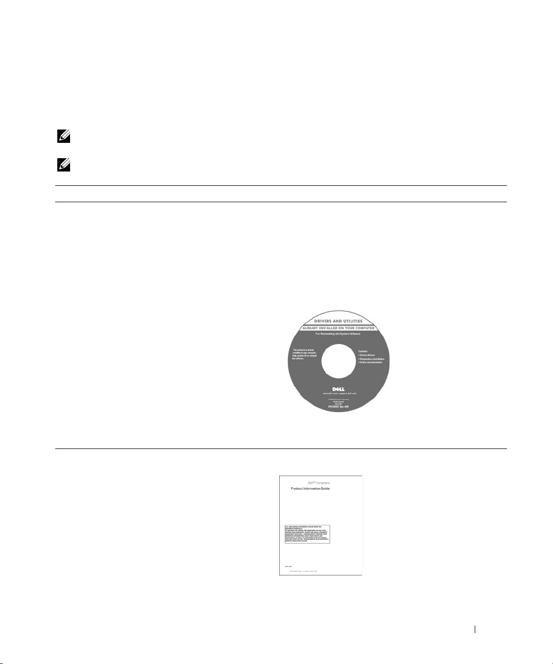
Drivers and Utilities CD (also known as ResourceCD)
NOTE: The Drivers and Utilities CD may be optional and may
not ship with your computer.
Documentation and drivers are already installed on your
computer. You can use the CD to reinstall drivers (see
"Reinstalling Drivers" on page 53), to run the Dell
Diagnostics (see "Dell Diagnostics" on page 50), or to
access your documentation.
Readme files may be
included on your CD to
provide last-minute
updates about technical
changes to your computer
or advanced technical
reference material for
technicians or experienced
users.
• Warranty information
• Terms and Conditions (U.S. only)
• Safety instructions
• Regulatory information
• Ergonomics information
• End User License Agreement
NOTE: Drivers and documentation updates can be found at
support.dell.com.
Dell™ Product Information Guide
Finding Information 9
Page 10
What Are You Looking For? Find It Here
• How to set up my computer
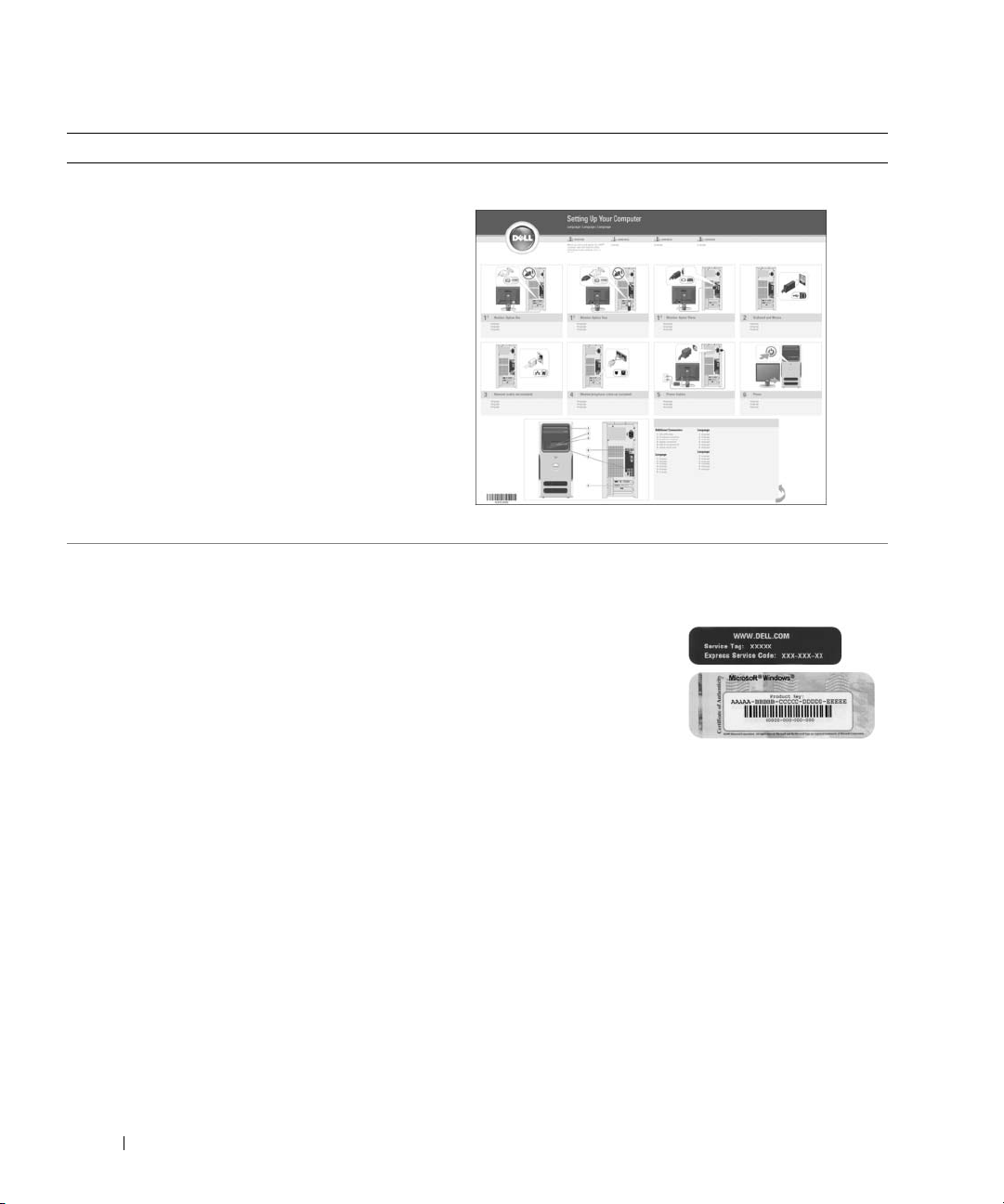
Setup Diagram
• Service Tag and Express Service Code
• Microsoft Windows License Label
Service Tag and Microsoft® Windows® License
These labels are located on your computer (see "Front View
of the Computer" on page 13).
• Use the Service Tag to
identify your computer
when you use
support.dell.com
contact support.
• Enter the Express
Service Code to direct your call when contacting support.
or
10 Finding Information
Page 11

What Are You Looking For? Find It Here
• Solutions — Troubleshooting hints and tips, articles
from technicians, online courses, and frequently asked
questions
Dell Support Website — support.dell.com
NOTE: Select your region or business segment to view the
appropriate support site.
• Community — Online discussion with other Dell
customers
• Upgrades — Upgrade information for components, such
as the memory, hard drive, and operating system
• Customer Care — Contact information, service call and
order status, warranty, and repair information
• Service and Support — Service call status, support
history, service contract, and online discussions with
support
• Reference — Computer documentation, details on my
computer configuration, product specifications, and
white papers
• Downloads — Certified drivers, patches, and software
updates
• Desktop System Software (DSS)— If you reinstall the
operating system for your computer, you should reinstall
the DSS utility prior to installing any drivers. DSS
provides critical updates for your operating system and
support for Dell™ 3.5-inch USB floppy drives, AMD
processors, optical drives, and USB devices. DSS is
necessary for correct operation of your Dell computer.
The software automatically detects your computer and
operating system and installs the updates appropriate
for your configuration.
• How to use Windows XP
• How to work with programs and files
• How to personalize my desktop
To download Desktop System Software:
1
Go to
™
support.dell.com
segment, and then enter your Service Tag.
2
Select
3
Click your operating system, and then search for the
keyword
NOTE: The support.dell.com user interface may vary
depending on your selections.
Windows Help and Support Center
1
Click
Start→
2
Type a word or phrase that describes your problem, and
then click the arrow icon.
3
Click the topic that describes your problem.
4
Follow the instructions on the screen.
, select your region or business
Drivers & Downloads
Desktop System Software
Help and Support
, then click Go.
.
.
Finding Information 11
Page 12
What Are You Looking For? Find It Here
• How to reinstall my operating system
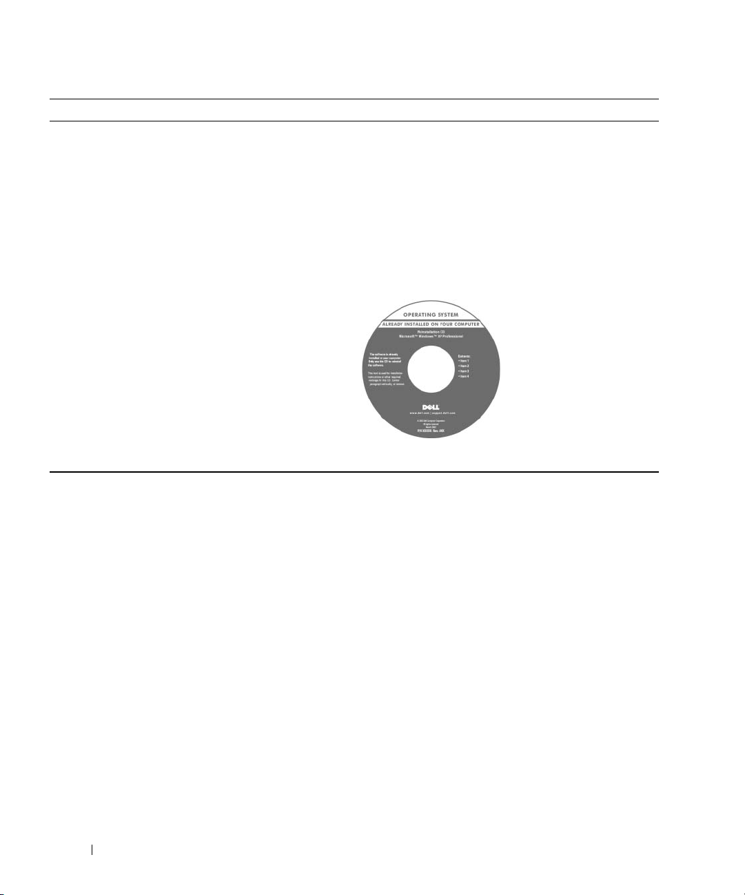
Operating System CD
NOTE: The Operating System CD may be optional and may
not ship with your computer.
The operating system is already installed on your computer.
To reinstall your operating system, use the Operating
System CD (see "Restoring Your Operating System" on
page 54).
NOTE: If you reinstall the operating system for your
computer, you should reinstall the DSS utility prior to
installing any drivers.
varies based on the operating system you ordered.
After you reinstall your
operating system, use the
Drivers and Utilities CD
(ResourceCD) to reinstall
drivers for the devices that
came with your computer.
Your operating system
product key label is located
on your computer.
NOTE: The color of your CD
12 Finding Information
Page 13
Setting Up and Using Your Computer
Front View of the Computer
1
2
3
4
5
6
7
8
9
10
11
12
1 cover release latch Use this latch to remove the cover (see "Front View of the
Computer" on page 13).
2 Service Tag Use to identify your computer when you access the Dell
Support website or call support.
Setting Up and Using Your Computer 13
Page 14
3 FlexBay drive Can contain an optional floppy drive or optional Media Card
Reader. For information on using the Media Card Reader, see
"Using a Media Card Reader (Optional)" on page 24.
4 CD or DVD activity light The drive light is on when the computer reads data from the
CD or DVD drive.
5 CD or DVD eject button Press to eject a disk from the CD or DVD drive.
6 microphone connector Use the microphone connector to attach a personal computer
microphone for voice or musical input into a sound or
telephony program.
7 headphone connector Use the headphone connector to attach headphones and most
kinds of speakers.
8 diagnostic lights (4) Use the lights to help you troubleshoot a computer problem
based on the diagnostic code. For more information, see "Power
Light and Diagnostic Lights" on page 47.
9 USB 2.0 connectors (2) Use the front USB connectors for devices that you connect
occasionally, such as joysticks or cameras, or for bootable USB
devices (see "System Setup Options" on page 98 for more
information on booting to a USB device).
It is recommended that you use the back USB connectors for
devices that typically remain connected, such as printers and
keyboards.
10 power button Press to turn on the computer.
NOTICE: To avoid losing data, do not use the power button
to turn off the computer. Instead, perform an operating
system shutdown.
11 hard-drive activity light The hard drive activity light is on when the computer reads
data from or writes data to the hard drive. The light might also
be on when a device such as a CD player is operating.
12 vents To ensure adequate cooling, do not block any of the vents.
14 Setting Up and Using Your Computer
NOTICE: Ensure that there is a minimum of two inches of
space between all vents and any object near these vents.
NOTICE: Keep the vent area clean and dust-free to ensure
that the system is adequately ventilated. Use only a dry
cloth to clean the vent area to avoid water damage to the
system.
Page 15
Back View of the Computer
1
2
3
4
1 voltage selection switch See the safety instructions in the Product Information Guide for more
information.
2 power connector Insert the power cable.
3 back panel I/O connectors Plug serial, USB, and other devices into the appropriate connectors (see "Back
Panel I/O Connectors" on page 16).
4 card slots (3) Access connector slots for expansion cards:
• SLOT1 PCI Express x16
• SLOT2 PCI Express x1
• SLOT3 PCI
Setting Up and Using Your Computer 15
Page 16
Back Panel I/O Connectors
5
6
7
8
910
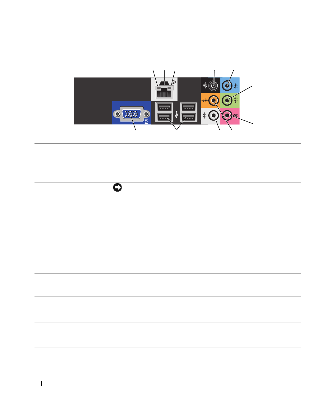
1 link integrity light
2 network adapter
connector
2113
1
• Green — A good connection exists between a 10-Mbps network and the
computer.
• Orange — A good connection exists between a 100-Mbps network and the
computer.
• Off — The computer is not detecting a physical connection to the network.
NOTICE: Do not plug a telephone cable into the network connector.
Use the network adapter connector to attach your computer to a network or
broadband device. Connect one end of a network cable to either a network jack or
your network or broadband device, and then connect the other end of the
network cable to the network adapter connector on your computer. A click
indicates that the network cable has been securely attached.
On computers with an additional network connector card, use the connectors on
the card and on the back of the computer when setting up multiple network
connections (such as a separate intra- and extranet).
4
NOTE: It is recommended that you use Category 5 wiring and connectors for your
network. If you must use Category 3 wiring, force the network speed to 10 Mbps to
ensure reliable operation.
3 network activity light Flashes a yellow light when the computer is transmitting or receiving network
data. A high volume of network traffic may make this light appear to be in a
steady "on" state.
4 surround sound
connector
5 line-in connector Use the (blue) line-in connector to attach a record/playback device such as a
Use the (black) surround sound connector to attach multichannel-capable
speakers.
On computers with a sound card, use the connector on the card.
cassette player, CD player, or VCR.
On computers with a sound card, use the connector on the card.
16 Setting Up and Using Your Computer
Page 17
6 line-out/headphone
connector
7 microphone connector Use the (pink) microphone connector to attach a personal computer microphone
8 center/subwoofer LFE
connector
Use the (green) line-out connector to attach headphones and most speakers with
integrated amplifiers.
On computers with a sound card, use the connector on the card.
for voice or musical input into a sound or telephony program.
On computers with a sound card, use the connector on the card.
Use the (orange) center/subwoofer connector to attach a center speaker or a
single subwoofer.
On computers with a sound card, use the connector on the card.
NOTE: The LFE (Low Frequency Effects) Audio channel, found in digital surround
sound audio schemes, carries only low frequency information of 80 Hz and below.
The LFE channel drives a subwoofer to provide extremely low bass extension.
Systems not using subwoofers can shunt the LFE information to the main speakers in
the surround sound setup.
9 side surround sound
connector
10 USB 2.0 connectors (4)
(rear quad)
Use the (gray) side surround sound connector to attach multichannel-capable
speakers. The side-surround output provides enhanced surround audio for
computers with 7.1 speakers.
On computers with a sound card, use the connector on the card.
Use the back, rear-quad USB connectors for devices that typically remain
connected, such as printers and keyboards.
NOTE: It is recommended that you use the front USB connectors for devices that
you connect occasionally, such as joysticks, cameras, or bootable USB devices.
11
VGA video connector If your monitor has a VGA connector, plug it into the VGA connector on the
computer.
Setting Up a Printer
NOTICE: Complete the operating system setup before you connect a printer to the computer.
See the documentation that came with the printer for setup information, including how to:
• Obtain and install updated drivers
• Connect the printer to the computer
• Load paper and install the toner or ink cartridge
For technical assistance, refer to the printer owner's manual or contact the printer manufacturer.
Printer Cable
Your printer connects to your computer with a USB cable. Your printer may not come with a printer cable, so
if you purchase a cable separately, ensure that it is compatible with your printer. If you purchased a printer
cable at the same time you purchased your computer, the cable may arrive in the computer box.
Setting Up and Using Your Computer 17
Page 18
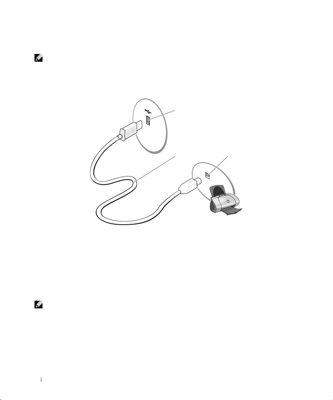
Connecting a USB Printer
NOTE: You can connect USB devices while the computer is turned on.
1
Complete the operating system setup, if you have not already done so.
2
Attach the USB printer cable to the USB connectors on the computer and the printer. The USB
connectors only fit into the ports when correctly oriented.
1
23
1 USB connector on
computer
3
Turn on the printer and then turn on the computer. If the
appears, click
4
Install the printer driver, if necessary. See the documentation that came with your printer.
Cancel
.
2 USB printer cable 3 USB connector on printer
Add New Hardware Wizard
window
Connecting to the Internet
NOTE: ISPs and ISP offerings vary by country.
To connect to the Internet, you need a modem or network connection and an Internet service provider
(ISP), such as AOL or MSN. Your ISP will offer one or more of the following Internet connection options:
• Dial-up connections that provide Internet access through a telephone line. Dial-up connections are
considerably slower than DSL and cable modem connections.
18 Setting Up and Using Your Computer
Page 19

• DSL connections that provide high-speed Internet access through your existing telephone line. With a
DSL connection, you can access the Internet and use your telephone on the same line simultaneously.
• Cable modem connections that provide high-speed Internet access through your local cable TV line.
If you are using a dial-up connection, connect a telephone line to the modem connector on your computer
and to the telephone wall jack before you set up your Internet connection. If you are using a DSL or cable
modem connection, contact your ISP for setup instructions.
Setting Up Your Internet Connection
To set up an Internet connection with a provided ISP desktop shortcut:
Save and close any open files, and exit any open programs.
1
2
Double-click the ISP icon on the Microsoft® Windows® desktop.
3
Follow the instructions on the screen to complete the setup.
If you do not have an ISP icon on your desktop or if you want to set up an Internet connection with a
different ISP:
1
Save and close any open files, and exit any open programs.
2
Click the
The
3
Click
4
In the next window, click the appropriate option:
• If you do not have an ISP and want to select one, click
• If you have already obtained setup information from your ISP, but you did not receive a setup CD,
• If you have a CD, click
5
Click
If you selected
on the screen to complete the setup.
Start
button, then click
New Connection Wizard
Connect to the Internet
providers (ISPs)
click
Set up my connection manually
.
Use the CD I got from an ISP
Next
.
Set up my connection manually
Internet Explorer
appears.
.
.
.
Choose from a list of Internet service
.
, continue to step 6. Otherwise, follow the instructions
NOTE: If you do not know which type of connection to select, contact your ISP.
6
Click the appropriate option under
7
Use the setup information provided by your ISP to complete the setup.
How do you want to connect to the Internet?
, and then click
Next
If you are having problems connecting to the Internet, see "E-Mail, Modem, and Internet Problems" on
page 33. If you cannot connect to the Internet but have successfully connected in the past, the ISP might
have a service outage. Contact your ISP to check the service status, or try connecting again later.
Setting Up and Using Your Computer 19
.
Page 20
Playing CDs and DVDs
NOTICE: Do not press down on the CD or DVD tray when you open or close it. Keep the tray closed when you are
not using the drive.
NOTICE: Do not move the computer when you are playing CDs or DVDs.
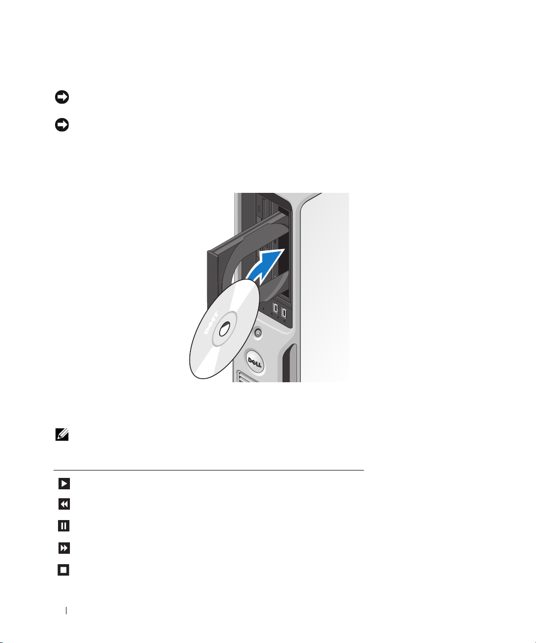
1
Press the eject button on the front of the drive.
2
Place the disc, label side up in the center of the tray.
3
Press the disc into the center of the tray until it clicks into place.
4
Press the eject button or gently push in the tray.
To format CDs for storing data, to create music CDs, or to copy CDs, see the CD software that came with
your computer.
NOTE: Ensure that you follow all copyright laws when you create CDs.
A CD player includes the following basic buttons:
Play
Move backward within the current track
Pau se
Move forward within the current track
Stop
20 Setting Up and Using Your Computer
Page 21
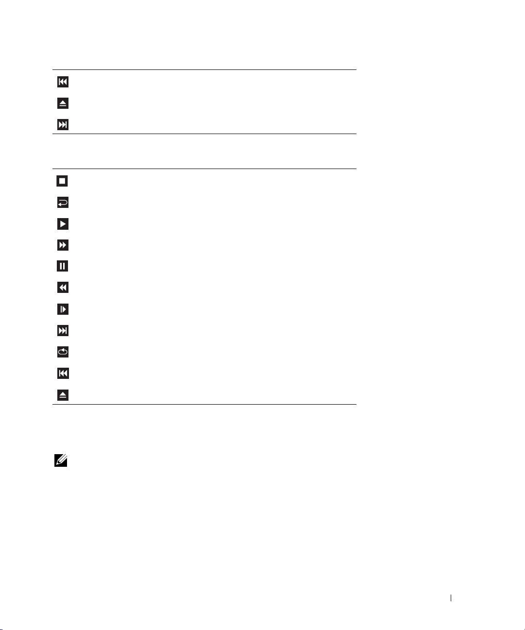
Go to the previous track
Eject
Go to the next track
A DVD player includes the following basic buttons:
Stop
Restart the current chapter
Play
Fast forward
Pau se
Fast reverse
Advance a single frame while in pause mode
Go to the next title or chapter
Continuously play the current title or chapter
Go to the previous title or chapter
Eject
Help
For more information on playing CDs or DVDs, click
on the CD or DVD player (if available).
Adjusting the Volume
NOTE: When the speakers are muted, you do not hear the CD or DVD playing.
1
Click the
Control
2
In the
increase or decrease the volume.
For more information on volume control options, click
Start
button, point to
.
Volume Control
All Programs → Accessories→ Entertainment
window, click and drag the bar in the
Help
in the
, and then click
Volume Control
Volume Control
Setting Up and Using Your Computer 21
column up or down to
window.
Volume
Page 22

Adjusting the Picture
If an error message notifies you that the current resolution and color depth are using too much memory and
preventing DVD playback, adjust the display properties:
1
Click the
2
Under
3
Under
4
In the
800 by 600 pixels
5
Click the drop-down menu under
6
Click OK.
Start
button, then click
Pick a category
Pick a task...
Display Properties
, click
, click
.
Control Panel
Appearance and Themes
Change the screen resolution
window, click and drag the bar in
Color quality
.
.
.
, then click
Screen resolution
Medium (16 bit)
to change the setting to
.
Copying CDs and DVDs
NOTE: Ensure that you observe all copyright laws when creating CDs or DVDs.
This section applies only to computers that have a CD-RW, DVD+/-RW, or CD-RW/DVD (combo)
drive.
NOTE: The types of CD or DVD drives offered by Dell may vary by country.
The following instructions explain how to make an exact copy of a CD or DVD using Roxio Creator Plus
- Dell Edition. You can also use Roxio Creator Plus for other purposes, such as creating music CDs from
audio files stored on your computer or backing up important data. For help, open Roxio Creator Plus,
and then click the question mark icon in the upper-right corner of the window.
How to Copy a CD or DVD
NOTE: CD-RW/DVD combo drives cannot write to DVD media. If you have a CD-RW/DVD combo drive and you
experience recording problems, check for available software patches on the Sonic support website at
www.sonic.com.
The DVD-writable drives installed in Dell computers can write to and read DVD+/-R, DVD+/-RW and
DVD+R DL (dual layer) media, but cannot write to and may not read DVD-RAM or DVD-R DL media.
NOTE: Most commercial DVDs have copyright protection and cannot be copied using Roxio Creator Plus.
1
Click
Start
, point to
2
Under the
3
To copy the CD or DVD:
•
22 Setting Up and Using Your Computer
Copy
If you have one CD/DVD drive
computer reads your source CD or DVD and copies the data to a temporary folder on your
computer hard drive.
When prompted, insert a blank CD or DVD into the drive and click
All Programs→ Roxio→ Creator Projects
tab, click
Disc Copy
, ensure that the settings are correct, and then click
.
, and then click
OK
.
RecordNow Copy
Disc Copy
.
. The
Page 23

•
If you have two CD/DVD drives
DVD, and then click
Disc Copy
, select the drive into which you have inserted your source CD or
. The computer copies the data from the source CD or DVD to the
blank CD or DVD.
Once you have finished copying the source CD or DVD, the CD or DVD that you have created
automatically ejects.
Using Blank CDs and DVDs
CD-RW drives can write to CD recording media only (including high-speed CD-RW media) while
DVD-writable drives can write to both CD and DVD recording media.
Use blank CD-Rs to record music or permanently store data files. After the maximum storage capacity of
a CD-R is reached, you cannot write to that CD-R again (see the Sonic documentation for more
information). Use blank CD-RWs if you plan to erase, rewrite, or update information on the CD later.
Blank DVD+/-Rs can be used to permanently store large amounts of data. After you create a DVD+/-R
disc, you may not be able to write to that disc again if the disc is finalized or closed during the final stage
of the disc creation process. Use blank DVD+/-RWs if you plan to erase, rewrite, or update information
on the disc later.
CD-Writable Drives
Media Type Read Write Rewritable
CD-R Yes Yes No
C D- RW Ye s Ye s Ye s
DVD-Writable Drives
Media Type Read Write Rewritable
CD-R Yes Yes No
C D- RW Ye s Ye s Ye s
DVD+R Yes Yes No
DVD-R Yes Yes No
DV D +R W Yes Ye s Ye s
DV D -R W Ye s Ye s Ye s
DVD+R DL Yes Yes No
Helpful Tips
• Use Microsoft® Windows® Explorer to drag and drop files to a CD-R or CD-RW only after you start
Roxio Creator Plus and open a Creator project.
Setting Up and Using Your Computer 23
Page 24

• Use CD-Rs to burn music CDs that you want to play in regular stereos. CD-RWs may not play in
many home or car stereos.
• You cannot create audio DVDs with Roxio Creator Plus.
• Music MP3 files can be played only on MP3 players or on computers that have MP3 software installed.
• Commercially available DVD players used in home theater systems may not support all available DVD
formats. For a list of formats supported by your DVD player, see the documentation provided with your
DVD player or contact the manufacturer.
• Do not burn a blank CD-R or CD-RW to its maximum capacity; for example, do not copy a 650-MB
file to a blank 650-MB CD. The CD-RW drive needs 1–2 MB of blank space to finalize the recording.
• Use a blank CD-RW to practice CD recording until you are familiar with CD recording techniques. If
you make a mistake, you can erase the data on the CD-RW and try again. You can also use blank
CD-RWs to test music file projects before you record the project permanently to a blank CD-R.
• See the Sonic website at
www.sonic.com
for additional information.
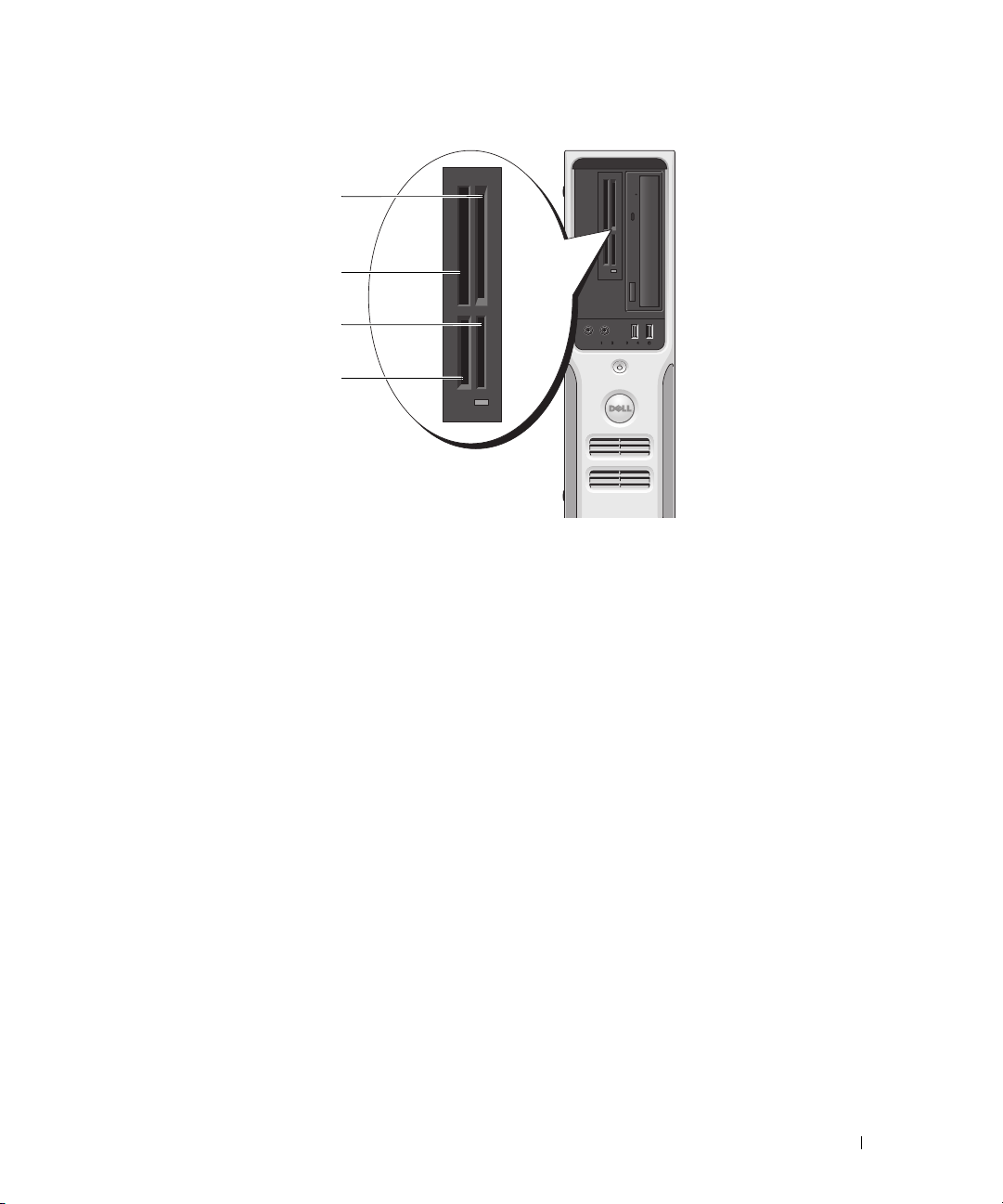
Using a Media Card Reader (Optional)
Use the Media Card Reader to transfer data directly to your computer.
The Media Card Reader supports the following memory types:
•xD-Picture Card
• SmartMedia (SMC)
• CompactFlash Type I and II (CF I/II)
• MicroDrive Card
• SecureDigital Card (SD)
• MultiMediaCard (MMC)
• Memory Stick (MS/MS Pro)
For information about installing or removing a Media Card Reader, see "Media Card Reader" on page 83.
24 Setting Up and Using Your Computer
Page 25
1
2
3
4
1 xD-Picture Card and
SmartMedia (SMC)
2 CompactFlash Type-I and II
(CF I/II) and MicroDrive Card
3 Memory Stick (MS/MS Pro)
4 SecureDigital Card (SD)/
MultiMediaCard (MMC)
To use the Media Card Reader:
Check the media or card to determine the proper orientation for insertion.
1
2
Slide the media or card into the appropriate slot until it is completely seated in the connector.
If you encounter resistance, do not force the media or card. Check the card orientation and try again.
Setting Up and Using Your Computer 25
Page 26
Setting Up a Home and Office Network
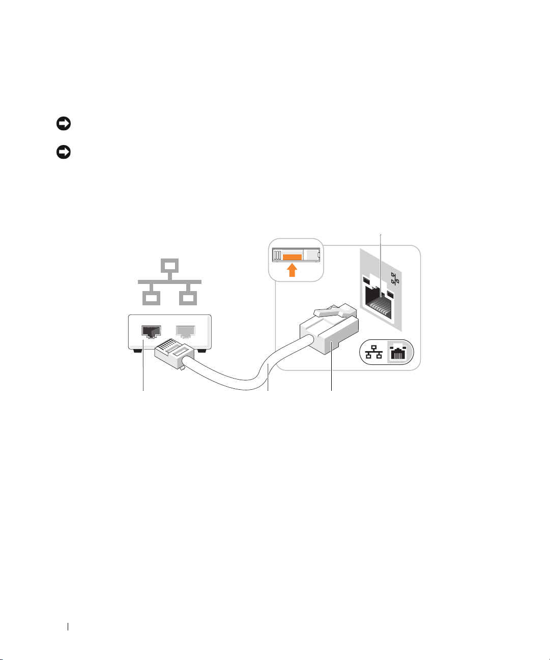
Connecting to a Network Adapter
NOTICE: Plug the network cable into the network adapter connector on the computer. Do not plug the network
cable into the modem connector on the computer.
NOTICE: Do not plug a network cable into a telephone wall jack.
1
Connect the network cable to the network adapter connector on the back of your computer.
Insert the cable until it clicks into place, and then gently pull it to ensure that it is secure.
2
Connect the other end of the network cable to a network device.
4
1
1 Network device 3 network adapter connector
2 network cable 4 network connector on the
26 Setting Up and Using Your Computer
2 3
back of the computer
Page 27

Network Setup Wizard
The Microsoft® Windows® XP operating system provides a Network Setup Wizard to guide you through
the process of sharing files, printers, or an Internet connection between computers in a home or small office.
1
Click the
Network Setup Wizard
2
On the welcome screen, click
3
Click
4
Complete the checklist and required preparations.
5
Return to the Network Setup Wizard and follow the instructions on the screen.
Start
button, point to
.
Checklist for creating a network
NOTE: Selecting the connection method This computer connects directly to the Internet enables the
integrated firewall provided with Windows XP.
All Programs→ Accessories→ Communications
Next
.
.
, and then click
Power Management
The Microsoft® Windows® XP power management features can reduce the amount of electricity your
computer uses when it is on and you are not using it. You can reduce power to just the monitor or the
hard drive, or you can use standby mode or hibernate mode to reduce power to the entire computer.
When the computer exits from a power conservation mode, the Windows desktop is restored to the state
it was in before it entered the mode.
NOTE: Windows XP Professional includes security and networking features not available in Windows XP Home
Edition. When a Windows XP Professional computer is connected to a network, different options related to security
and networking appear in certain windows.
Standby Mode
Standby mode conserves power by turning off the display and the hard drive after a time-out. When the
computer exits from standby mode, it returns to the operating state it was in before it entered standby
mode.
To set standby mode to automatically activate after a defined period of inactivity:
1
Click the
2If Switch to Category View
Category View
3
Under
4
Under
5
Under the
and then click
Start
button, then click
.
Pick a category
or pick a Control Panel icon
Power Schemes
OK
, click
.
Control Panel
appears in the
Performance and Maintenance
tab, change the settings in the drop-down boxes to those that you desire,
Control Panel
, click
Power Options
.
in the left of the window, click
.
.
Setting Up and Using Your Computer 27
Switch to
Page 28

To immediately activate standby mode without a period of inactivity, click the Start button, click Tu r n
Off Computer, and then click Stand by.
To exit from standby mode, press a key on the keyboard or move the mouse.
NOTICE: If your computer loses power while in standby mode, it may lose data.
Hibernate Mode
Hibernate mode conserves power by copying system data to a reserved area on the hard drive and then
completely turning off the computer. When the computer exits from hibernate mode, the desktop is
restored to the state it was in
To activate hibernate mode:
Click the
1
2
Under
3
Under
4
Define your hibernate settings on the
"Power Options Properties" on page 28).
To exit from hibernate mode, press the power button. The computer may take a short time to exit from
hibernate mode. Pressing a key on the keyboard or moving the mouse does not bring the computer out of
hibernation because the keyboard and the mouse do not function when the computer is in hibernate
mode.
Because hibernate mode requires a special file on your hard drive with enough disk space to store the
contents of the computer memory, Dell creates an appropriately sized hibernate mode file before
shipping the computer to you. If the computer’s hard drive becomes corrupted, Windows XP recreates
the hibernate file automatically.
Start
button, then click
Pick a category
or pick a Control Panel icon
before it entered hibernate mode.
Control Panel
, click
Performance and Maintenance
, click
Power Schemes
.
Power Options
.
tab,
.
Advanced
tab, and
Hibernate
tab (see
Power Options Properties
Define your standby mode settings, hibernate mode settings, and other power settings in the Power
Options Properties window.
1
Click the
2
Under
3
Under
4
Define your power settings on the
Start
button, then click
Pick a category
or pick a Control Panel icon
Power Schemes Tab
Each standard power setting is called a scheme. If you want to select one of the standard Windows
schemes installed on your computer, choose a scheme from the Power schemes drop-down menu. The
settings for each scheme appear in the fields below the scheme name. Each scheme has different settings
for starting standby or hibernate mode and for turning off the monitor and hard drive.
28 Setting Up and Using Your Computer
To access the Power Options Properties window:
Control Panel
, click
Performance and Maintenance
, click
Power Schemes
.
Power Options
tab,
Advanced
.
.
tab, and
Hibernate
tab.
Page 29

The Power schemes drop-down menu displays the following schemes:
•
Always On
Home/Office Desk
•
(default) — If you want to use your computer with no power conservation.
— If you use your computer as a home or office computer and you require minimal
power conservation.
•
Portable/Laptop
•
Presentation
•
Minimal Power Management
Max Battery
•
— If your computer is a portable computer that you use for traveling.
— If you want your computer to run without interruption (using no power conservation).
— If you want your computer to run with minimal power conservation.
— If your computer is a portable computer and you run your computer from batteries for
extended periods of time.
If you want to change the default settings for a scheme, click the drop-down menu in the Turn off
monitor, Turn off hard disks, System standby, or System hibernates field, and then select a time-out
from the displayed list. Changing the time-out for a scheme field permanently changes the default
settings for that scheme, unless you click Save As and enter a new name for the changed scheme.
NOTICE: If you set the hard drive (hard disk) to time-out before the monitor does, your computer may appear to be
locked up. To recover, press any key on the keyboard or click the mouse. To avoid this problem, always set the
monitor to time-out before the hard drive.
Advanced Tab
The Advanced tab allows you to:
• Place the power options icon in the Windows taskbar for quick access.
• Set the computer to prompt you for your Windows password before the computer exits from standby
mode or hibernate mode.
• Program the power button to activate standby mode, activate hibernate mode, or turn off the
computer.
To program these functions, click an option from the corresponding drop-down menu, and then
click OK.
Hibernate Tab
The Hibernate tab allows you to enable hibernate mode. If you want to use the hibernate settings you
defined on the Power Schemes tab, click the Enable hibernate support check box on the Hibernate tab.
For more information on power management options:
1
Click the
2
In the
3
In the
Start
button, then click
Help and Support
window, click
Help and Support
Performance and maintenance
.
Performance and maintenance
window, click
Conserving power on your computer
Setting Up and Using Your Computer 29
.
.
Page 30

Enabling Cool ’n’ Quiet™ Technology
The Cool ’n’ Quiet technology controls your computer’s processor performance automatically,
dynamically adjusting the operating frequency and voltage, according to the task at hand. When an
application does not require full performance, significant amounts of power can be saved. Performance is
designed to still be responsive, with maximum processor performance being delivered when required,
and automatic power savings when possible.
1
Enter system setup, select
setting to
2
Click on the
window.
3
From the
Management
Cool ’n’ Quiet technology is now enabled.
On
(see "System Setup Options" on page 98).
Start→Settings→Control Panel→Power Options
Power Schemes
and then click OK.
Cool and Quiet
tab, click the Power Schemes drop-down menu and select
from the
Power Management
to access the
group, and change the
Power Options Properties
Minimal Power
30 Setting Up and Using Your Computer
Page 31
Solving Problems
Troubleshooting Tips
Follow these tips when you troubleshoot your computer:
• If you added or removed a part before the problem started, review the installation procedures and
ensure that the part is correctly installed.
• If a peripheral device does not work, ensure that the device is properly connected.
• If an error message appears on the screen, write down the exact message. This message may help
support personnel diagnose and fix the problem.
• If an error message occurs in a program, see the program’s documentation.
Battery Problems
CAUTION: There is a danger of a new battery exploding if it is incorrectly installed. Replace the battery
only with the same or equivalent type recommended by the manufacturer. Discard used batteries according
to the manufacturer's instructions.
CAUTION: Before you begin any of the procedures in this section, follow the safety instructions located in
the Product Information Guide.
REPLACE THE BATTERY — If you have to repeatedly reset time and date information after turning on
the computer, or if an incorrect time or date displays during start-up, replace the battery (see
on page 89
). If the battery still does not work properly, contact Dell (see
"Contacting Dell" on page 108
"Battery"
).
Drive Problems
CAUTION: Before you begin any of the procedures in this section, follow the safety instructions located in
the Product Information Guide.
ENSURE THAT MICROSOFT® WINDOWS® RECOGNIZES THE DRIVE — Click the Start button, then
click My Computer. If the floppy, CD, or DVD drive, is not listed, perform a full scan with your
antivirus software to check for and remove viruses. Viruses can sometimes prevent Windows from
recognizing the drive.
Solving Problems 31
Page 32
TEST THE DRIVE —
• Insert another floppy disk, CD, or DVD to eliminate the possibility that the original one is defective.
• Insert a bootable floppy disk and restart the computer.
CLEAN THE DRIVE OR DISK — See
CHECK THE CABLE CONNECTIONS
RUN THE HARDWARE TROUBLESHOOTER — See
on page 54
RUN THE DELL DIAGNOSTICS — See
.
"Cleaning Your Computer" on page 105
"Resolving Software and Hardware Incompatibilities"
"Dell Diagnostics" on page 50
.
.
CD and DVD drive problems
NOTE: High-speed CD or DVD drive vibration is normal and may cause noise, which does not indicate a defect in
the drive or the CD or DVD.
NOTE: Because of different regions worldwide and different disc formats, not all DVD titles work in all DVD drives.
ADJUST THE WINDOWS VOLUME CONTROL —
• Click the speaker icon in the lower-right corner of your screen.
• Ensure that the volume is turned up by clicking the slidebar and dragging it up.
• Ensure that the sound is not muted by clicking any boxes that are checked.
CHECK THE SPEAKERS AND SUBWOOFER — See "Sound and Speaker Problems" on page 43.
Problems writing to a CD/DVD-RW drive
CLOSE OTHER PROGRAMS — The CD/DVD-RW drive must receive a steady stream of data when
writing. If the stream is interrupted, an error occurs. Try closing all programs before you write to the
CD/DVD-RW.
32 Solving Problems
Page 33
TURN OFF STANDBY MODE IN WINDOWS BEFORE WRITING TO A CD/DVD-RW DISC —
1
Click the
2
Under
3
Under
4
From the
Start
button and click
Pick a Category
, click
Control Panel
Performance and Maintenance
or pick a Control Panel icon
Power Schemes
tab, select
, click
Power Options
Always On
.
.
.
.
Hard drive problems
RUN CHECK DISK —
1
Click the
2
Right-click
3
Click
4
Click the
5
Under
6
Click
7
Click
Start
button, then click
Local Disk C:
Properties
Tools
.
tab.
Error-checking
, click
.
Check Now
My Computer
.
.
Scan for and attempt recovery of bad sectors
Start
.
.
E-Mail, Modem, and Internet Problems
CAUTION: Before you begin any of the procedures in this section, follow the safety instructions located in the
Product Information Guide.
NOTE: Connect the modem to an analog telephone jack only. The modem does not operate while it is connected to
a digital telephone network.
CHECK THE MICROSOFT OUTLOOK® EXPRESS SECURITY SETTINGS — If you cannot open your
e-mail attachments:
1
In Outlook Express, click
2
Click
Do not allow attachments
To ol s
, click
Options
to remove the checkmark.
, and then click
Security
.
Solving Problems 33
Page 34

CHECK THE TELEPHONE LINE CONNECTION —
HECK THE TELEPHONE JACK —
C
C
ONNECT THE MODEM DIRECTLY TO THE TELEPHONE WALL JACK —
SE A DIFFERENT TELEPHONE LINE —
U
• Verify that the telephone line is connected to the jack on the modem. The jack has either a green label
or a connector-shaped icon next to it.
• Ensure that you hear a click when you insert the telephone line connector into the modem.
• Disconnect the telephone line from the modem and connect it to a telephone. Listen for a dial tone.
• If you have other telephone devices sharing the line, such as an answering machine, fax machine, surge
protector, or line splitter, bypass them and use the telephone to connect the modem directly to the
telephone wall jack. If you are using a line that is 3 m (10 ft) or more in length, try a shorter one.
RUN THE MODEM HELPER DIAGNOSTICS — Click the Start button, point to All Programs, and then
click Modem Helper. Follow the instructions on the screen to identify and resolve modem problems.
Modem Helper is not available on all computers.
VERIFY THAT THE MODEM IS COMMUNICATING WITH WINDOWS —
1
Click the
2
Click
3
Click
4
Click the
5
Click the COM port for your modem.
6
Click
Start
button, then click
Control Panel
Printers and Other Hardware
Phone and Modem Options
Modems
Properties
tab.
, click the
Diagnostics
.
.
.
tab, and then click
Query Modem
to verify that the modem is
communicating with Windows.
If all commands receive responses, the modem is operating properly.
ENSURE THAT YOU ARE CONNECTED TO THE INTERNET — Ensure that you have subscribed to an
Internet provider. With the Outlook Express e-mail program open, click File. If Work Offline has a
checkmark next to it, click the checkmark to remove it and connect to the Internet. For help, contact
your Internet service provider.
Error Messages
If the message is not listed, see the documentation for the operating system or the program that was running
when the message appeared.
A FILENAME CANNOT CONTAIN ANY OF THE FOLLOWING CHARACTERS: \ / : * ? “ < > | — Do not
use these characters in filenames.
34 Solving Problems
Page 35
A REQUIRED .DLL FILE WAS NOT FOUND — The program that you are trying to open is missing an
essential file. To remove and then reinstall the program:
1
Click the
2
Select the program you want to remove.
3
Click the
4
See the program documentation for installation instructions.
drive letter :\ IS NOT ACCESSIBLE. THE DEVICE IS NOT READY — The drive cannot read the disk.
Insert a disk into the drive and try again.
INSERT BOOTABLE MEDIA — Insert a bootable floppy disk or CD.
NON-SYSTEM DISK ERROR — Remove the floppy disk from the drive and restart your computer.
NOT ENOUGH MEMORY OR RESOURCES. CLOSE SOME PROGRAMS AND TRY AGAIN — Close all
windows and open the program that you want to use. In some cases, you might have to restart your
computer to restore computer resources. If so, run the program that you want to use first.
Start
button, click
Change or Remove Program
Control Panel
, and then click
icon.
Add or Remove Programs
.
OPERATING SYSTEM NOT FOUND — Contact Dell (see
"Contacting Dell" on page 108
).
Keyboard Problems
CAUTION: Before you begin any of the procedures in this section, follow the safety instructions located in the
Product Information Guide.
CHECK THE KEYBOARD CABLE —
• Ensure that the keyboard cable is firmly connected to the computer.
• Shut down the computer (see "Turning Off Your Computer" on page 59), reconnect the keyboard cable
as shown on the setup diagram for your computer, and then restart the computer.
• Ensure that the cable is not damaged or frayed and check cable connectors for bent or broken pins.
Straighten any bent pins.
• Remove keyboard extension cables and connect the keyboard directly to the computer.
TEST THE KEYBOARD — Connect a properly working keyboard to the computer. Then, try using the
keyboard.
Solving Problems 35
Page 36
RUN THE HARDWARE TROUBLESHOOTER — See
on page 54
.
"Resolving Software and Hardware Incompatibilities"
Lockups and Software Problems
CAUTION: Before you begin any of the procedures in this section, follow the safety instructions located in the
Product Information Guide.
The computer does not start up
CHECK THE DIAGNOSTIC LIGHTS — See
ENSURE THAT THE POWER CABLE IS FIRMLY CONNECTED TO THE COMPUTER AND TO THE
E
LECTRICAL OUTLET
"Power Light and Diagnostic Lights" on page 47
.
The computer stops responding
NOTICE: You might lose data if you are unable to perform an operating system shutdown.
TURN THE COMPUTER OFF — If you are unable to get a response by pressing a key on your keyboard or
moving your mouse, press and hold the power button for at least 8 to 10 seconds until the computer
turns off, then restart your computer.
A program stops responding
END THE PROGRAM —
1
Press <Ctrl><Shift><Esc> simultaneously.
2
Click
Applications
3
Click the program that is no longer responding.
4
Click
End Task
.
.
A program crashes repeatedly
NOTE: Software usually includes installation instructions in its documentation or on a floppy disk or CD.
CHECK THE SOFTWARE DOCUMENTATION — If necessary, uninstall and then reinstall the program.
36 Solving Problems
Page 37

A program is designed for an earlier Windows operating system
RUN THE PROGRAM COMPATIBILITY WIZARD —
The Program Compatibility Wizard configures a program so it runs in an environment similar to nonWindows XP operating system environments.
1
Click the
Wizard
2
In the welcome screen, click
3
Follow the instructions on the screen.
Start
button, point to
.
All Programs→ Accessories
Next
.
, and then click
Program Compatibility
A solid blue screen appears
TURN THE COMPUTER OFF — If you are unable to get a response by pressing a key on your keyboard or
moving your mouse, press and hold the power button for at least 8 to 10 seconds until the computer
turns off, then restart your computer.
Other software problems
CHECK THE SOFTWARE DOCUMENTATION OR CONTACT THE SOFTWARE MANUFACTURER FOR
TROUBLESHOOTING INFORMATION —
• Ensure that the program is compatible with the operating system installed on your computer.
• Ensure that your computer meets the minimum hardware requirements needed to run the software. See
the software documentation for information.
• Ensure that the program is installed and configured properly.
• Verify that the device drivers do not conflict with the program.
• If necessary, uninstall and then reinstall the program.
BACK UP YOUR FILES IMMEDIATELY
USE A VIRUS-SCANNING PROGRAM TO CHECK THE HARD DRIVE, FLOPPY DISKS, OR CDS
SAVE AND CLOSE ANY OPEN FILES OR PROGRAMS AND SHUT DOWN YOUR COMPUTER THROUGH THE
START MENU
Solving Problems 37
Page 38

Media Card Reader Problems
NO DRIVE LETTER IS ASSIGNED —
When Microsoft Windows XP detects the Media Card Reader, the device is automatically assigned a
drive letter as the next logical drive after all other physical drives in the system. If the next logical drive
after the physical drives is mapped to a network drive, Windows XP does not automatically assign a
drive letter to the Media Card Reader.
To manually assign a drive for the Media Card Reader:
1
Right-click My Computer, then select
2
Select the
3
Right-click the corresponding drive letter in the right pane that needs to be changed.
4
Select
5
From the drop-down list, select the new drive letter assignment for the Media Card Reader.
6
Click OK to confirm your selection.
Disk Management
Drive Letter and Paths.
option.
NOTE: Each slot in the Media Card Reader is mapped to a drive letter. A Media Card Reader slot only
appears as a mapped drive when a media card is installed in it. If you attempt to access a drive that is
mapped to an empty Media Card Reader slot, you are prompted to insert media.
FLEXBAY DEVICE IS DISABLED —
There is a FlexBay disable option in the BIOS setup that appears only when the FlexBay device is
installed. If the FlexBay device is physically installed, but it is not running, check to see if it is enabled in
the BIOS setup.
Manage
.
Memory Problems
CAUTION: Before you begin any of the procedures in this section, follow the safety instructions located in the
Product Information Guide.
IF YOU RECEIVE AN INSUFFICIENT MEMORY MESSAGE —
• Save and close any open files and exit any open programs you are not using to see if that resolves the
problem.
• See the software documentation for minimum memory requirements. If necessary, install additional
memory (see "Memory" on page 64).
• Reseat the memory modules (see "Memory" on page 64) to ensure that your computer is successfully
communicating with the memory.
• Run the Dell Diagnostics (see "Dell Diagnostics" on page 50).
38 Solving Problems
Page 39
IF YOU EXPERIENCE OTHER MEMORY PROBLEMS —
• Reseat the memory modules (see "Memory" on page 64) to ensure that your computer is successfully
communicating with the memory.
• Ensure that you are following the memory installation guidelines (see "Memory" on page 64).
• Your computer supports DDR2 memory. For more information about the type of memory supported by
your computer, see "Memory" on page 64.
• Run the Dell Diagnostics (see "Dell Diagnostics" on page 50).
Mouse Problems
CAUTION: Before you begin any of the procedures in this section, follow the safety instructions located in the
Product Information Guide.
CLEAN THE MOUSE — For instructions on cleaning the mouse, see
"Mouse" on page 106
.
CHECK THE MOUSE CABLE —
1
Remove mouse extension cables, if used, and connect the mouse directly to the computer.
2
Reconnect the mouse cable as shown in the setup diagram for your computer.
RESTART THE COMPUTER —
1
Simultaneously press <Ctrl><Esc> to display the
2
Ty p e u, press the keyboard arrow keys to highlight
3
After the computer turns off, reconnect the mouse cable as shown on the on the setup diagram for your
Start
menu.
Shut down
or
Turn Off
, and then press <Enter>.
computer.
4
Start the computer.
TEST THE MOUSE — Connect a properly working mouse to the computer, and try using the mouse.
CHECK THE MOUSE SETTINGS —
1
Click the
2
Click
3
Try adjusting the settings.
Start
Mouse
button, click
.
Control Panel
, and then click
Printers and Other Hardware
.
REINSTALL THE MOUSE DRIVER — See "Reinstalling Drivers" on page 53.
RUN THE HARDWARE TROUBLESHOOTER — See
on page 54
.
"Resolving Software and Hardware Incompatibilities"
Solving Problems 39
Page 40
Network Problems
CAUTION: Before you begin any of the procedures in this section, follow the safety instructions located in the
Product Information Guide.
CHECK THE NETWORK CABLE CONNECTOR — Ensure that the network cable is firmly inserted into
both the network connector on the back of the computer and the network port or device.
CHECK THE NETWORK LIGHTS ON THE BACK OF THE COMPUTER — If the link integrity light is off,
that indicates no network communication exists. Replace the network cable. For a description of
network lights, see
RESTART THE COMPUTER AND LOG ON TO THE NETWORK AGAIN
CHECK YOUR NETWORK SETTINGS — Contact your network administrator or the person who set up
your network to verify that your network settings are correct and that the network is functioning.
RUN THE HARDWARE TROUBLESHOOTER — See "Resolving Software and Hardware Incompatibilities"
on page 54.
"Back Panel I/O Connectors" on page 16
.
Power Problems
CAUTION: Before you begin any of the procedures in this section, follow the safety instructions located in the
Product Information Guide.
IF THE POWER LIGHT IS GREEN AND THE COMPUTER IS NOT RESPONDING — See "Power Light and
Diagnostic Lights" on page 47.
IF THE POWER LIGHT IS BLINKING GREEN — The computer is in standby mode. Press a key on the
keyboard, move the mouse, or press the power button to resume normal operation.
40 Solving Problems
Page 41
IF THE POWER LIGHT IS OFF — The computer is either turned off or is not receiving power.
• Reseat the power cable into both the power connector on the back of the computer and the electrical
outlet.
• If the computer is plugged into a power strip, ensure that the power strip is plugged into an electrical
outlet and that the power strip is turned on. Also bypass power protection devices, power strips, and
power extension cables to verify that the computer turns on properly.
• Ensure that the electrical outlet is working by testing it with another device, such as a lamp.
• Ensure that the main power cable and front panel cable are securely connected to the system board (see
"System Board Components" on page 63).
IF THE POWER LIGHT IS STEADY AMBER — A device might be malfunctioning or incorrectly installed.
• Remove and then reinstall the memory modules (see "Memory" on page 64).
• Remove and then reinstall any cards (see "Cards" on page 68).
IF THE POWER LIGHT IS BLINKING AMBER — The computer is receiving electrical power, but an
internal power problem might exist.
• Ensure that the voltage selection switch is set to match the AC power at your location (if applicable).
• Ensure that the processor power cable is securely connected to the system board (see "System Board
Components" on page 63).
ELIMINATE INTERFERENCE — Some possible causes of interference are:
• Power, keyboard, and mouse extension cables.
• Too many devices on a power strip.
• Multiple power strips connected to the same electrical outlet.
Printer Problems
CAUTION: Before you begin any of the procedures in this section, follow the safety instructions located in the
Product Information Guide.
NOTE: If you need technical assistance for your printer, contact the printer’s manufacturer.
CHECK THE PRINTER DOCUMENTATION — See the printer documentation for setup and
troubleshooting information.
ENSURE THAT THE PRINTER IS TURNED ON
Solving Problems 41
Page 42
CHECK THE PRINTER CABLE CONNECTIONS —
• See the printer documentation for cable connection information.
• Ensure that the printer cables are securely connected to the printer and the computer (see "Setting Up a
Printer" on page 17).
TEST THE ELECTRICAL OUTLET — Ensure that the electrical outlet is working by testing it with another
device, such as a lamp.
VERIFY THAT THE PRINTER IS RECOGNIZED BY WINDOWS —
1
Click the
2
Click
If the printer is listed, right-click the printer icon.
3
Click
port(s):
REINSTALL THE PRINTER DRIVER — See the printer documentation for instructions.
Start
button, click
View installed printers or fax printers
Properties, then
setting is
USB
Control Panel
click the
.
Ports
tab. For a USB printer, ensure that the
, and then click
.
Printers and Other Hardware
Print to the following
.
Scanner Problems
CAUTION: Before you begin any of the procedures in this section, follow the safety instructions located in the
Product Information Guide.
NOTE: If you need technical assistance for your scanner, contact the scanner’s manufacturer.
CHECK THE SCANNER DOCUMENTATION — See the scanner documentation for setup and
troubleshooting information.
UNLOCK THE SCANNER — Ensure that your scanner is unlocked if it has a locking tab or button.
RESTART THE COMPUTER AND TRY THE SCANNER AGAIN
CHECK THE CABLE CONNECTIONS —
• See the scanner documentation for cable connection information.
• Ensure that the scanner cables are securely connected to the scanner and the computer.
42 Solving Problems
Page 43
VERIFY THAT THE SCANNER IS RECOGNIZED BY MICROSOFT WINDOWS —
1
Click the
2
Click
If your scanner is listed, Windows recognizes the scanner.
REINSTALL THE SCANNER DRIVER — See the scanner documentation for instructions.
Start
button, click
Scanners and Cameras
Control Panel
.
, and then click
Printers and Other Hardware
.
Sound and Speaker Problems
CAUTION: Before you begin any of the procedures in this section, follow the safety instructions located in the
Product Information Guide.
No sound from speakers
NOTE: The volume control in some MP3 players overrides the Windows volume setting. If you have been listening
to MP3 songs, ensure that you did not turn the player volume down or off.
CHECK THE SPEAKER CABLE CONNECTIONS — Ensure that the speakers are connected as shown on
the setup diagram supplied with the speakers. If you purchased a sound card, ensure that the speakers
are connected to the card.
ENSURE THAT THE CORRECT AUDIO SOLUTION IS ENABLED IN THE BIOS SETUP PROGRAM — See
"System Setup" on page 97.
ENSURE THAT THE SUBWOOFER AND THE SPEAKERS ARE TURNED ON — See the setup diagram
supplied with the speakers. If your speakers have volume controls, adjust the volume, bass, or treble to
eliminate distortion.
ADJUST THE WINDOWS VOLUME CONTROL — Click or double-click the speaker icon in the lower-right
corner of your screen. Ensure that the volume is turned up and that the sound is not muted.
DISCONNECT HEADPHONES FROM THE HEADPHONE CONNECTOR — Sound from the speakers is
automatically disabled when headphones are connected to the computer’s front-panel headphone
connector.
TEST THE ELECTRICAL OUTLET — Ensure that the electrical outlet is working by testing it with another
device, such as a lamp.
Solving Problems 43
Page 44
ELIMINATE POSSIBLE INTERFERENCE — Turn off nearby fans, fluorescent lights, or halogen lamps to
check for interference.
REINSTALL THE SOUND DRIVER — See "Reinstalling Drivers" on page 53.
RUN THE HARDWARE TROUBLESHOOTER — See "Resolving Software and Hardware Incompatibilities"
on page 54.
No sound from headphones
CHECK THE HEADPHONE CABLE CONNECTION — Ensure that the headphone cable is securely inserted
into the headphone connector (see "Front View of the Computer" on page 13).
ADJUST THE WINDOWS VOLUME CONTROL — Click or double-click the speaker icon in the lower-right
corner of your screen. Ensure that the volume is turned up and that the sound is not muted.
ENSURE THAT THE CORRECT AUDIO SOLUTION IS ENABLED IN THE BIOS SETUP PROGRAM — See
"System Setup" on page 97.
Video and Monitor Problems
CAUTION: Before you begin any of the procedures in this section, follow the safety instructions located in the
Product Information Guide.
NOTE: See the monitor documentation for troubleshooting procedures.
The screen is blank
CHECK THE MONITOR CABLE CONNECTION —
• Ensure that the graphics cable is connected as shown on the setup diagram for your computer.
If an optional video card is installed, check that the monitor cable is connected to the card, rather than
the video connector on the system board.
• If you are using a graphics extension cable and removing the cable solves the problem, the cable is
defective.
• Swap the computer and monitor power cables to determine if the power cable is defective.
• Check the connector for bent or broken pins. It is normal for monitor cable connectors to have missing
pins.
44 Solving Problems
Page 45

CHECK THE MONITOR POWER LIGHT — If the power light is off, firmly press the button to ensure that
the monitor is turned on. If the power light is lit or blinking, the monitor has power. If the power light is
blinking, press a key on the keyboard or move the mouse.
TEST THE ELECTRICAL OUTLET — Ensure that the electrical outlet is working by testing it with another
device, such as a lamp.
CHECK THE DIAGNOSTIC LIGHTS — See "Power Light and Diagnostic Lights" on page 47.
The screen is difficult to read
CHECK THE MONITOR SETTINGS — See the monitor documentation for instructions on adjusting the
contrast and brightness, demagnetizing (degaussing) the monitor, and running the monitor self-test.
MOVE THE SUBWOOFER AWAY FROM THE MONITOR — If your speaker system includes a subwoofer,
ensure that the subwoofer is at least 60 cm (2 ft) away from the monitor.
MOVE THE MONITOR AWAY FROM EXTERNAL POWER SOURCES — Fans, fluorescent lights, halogen
lamps, and other electrical devices can cause the screen image to appear "shaky." Turn off nearby devices
to check for interference.
ROTATE THE MONITOR TO ELIMINATE SUNLIGHT GLARE AND POSSIBLE INTERFERENCE
ADJUST THE WINDOWS DISPLAY SETTINGS —
1
Click
Start
, click
Control Panel
2
Click
Display, then
3
Try different settings for
click the
, and then click
Settings
tab.
Screen resolution
and
Appearance and Themes
Color quality.
.
Solving Problems 45
Page 46

46 Solving Problems
Page 47
Advanced Troubleshooting
Power Light and Diagnostic Lights
CAUTION: Before you begin any of the procedures in this section, follow the safety instructions located in
the Product Information Guide.
Your computer has a power light and four lights labeled "1," "2," "3," and "4" on the front panel to
help you troubleshoot problems (see "Front View of the Computer" on page 13). When the
computer starts normally, the diagnostic lights flash. If the computer malfunctions, the color and
sequence of the lights identify the problem.
Power Light
Power Light Problem Description Suggested Resolution
Off The computer is in a normal "off" condition
or in a power-conserving mode.
Solid green The computer has successfully booted and
is operating normally.
Blinking green The computer is in a Windows standby
power-saving state (S1 or S3).
Solid Amber A pre-POST failure has occurred. The
system has received a Power Good signal
from the power supply.
Blinking Amber A possible power supply failure has
occurred. The system has not received a
Power Good signal from the power supply
None. Press the power button to wake the
computer or to turn the computer on.
None.
None. Move the mouse, press the spacebar,
or use another device that has been
configured as a wake-up device to wake the
computer.
See "Diagnostic Lights" on page 48 for
more information.
If this does not resolve your problem,
contact Dell (see "Contacting Dell" on
page 108).
Plug the computer into a working
electrical outlet. Also see "Power Problems"
on page 40.
Advanced Troubleshooting 47
Page 48
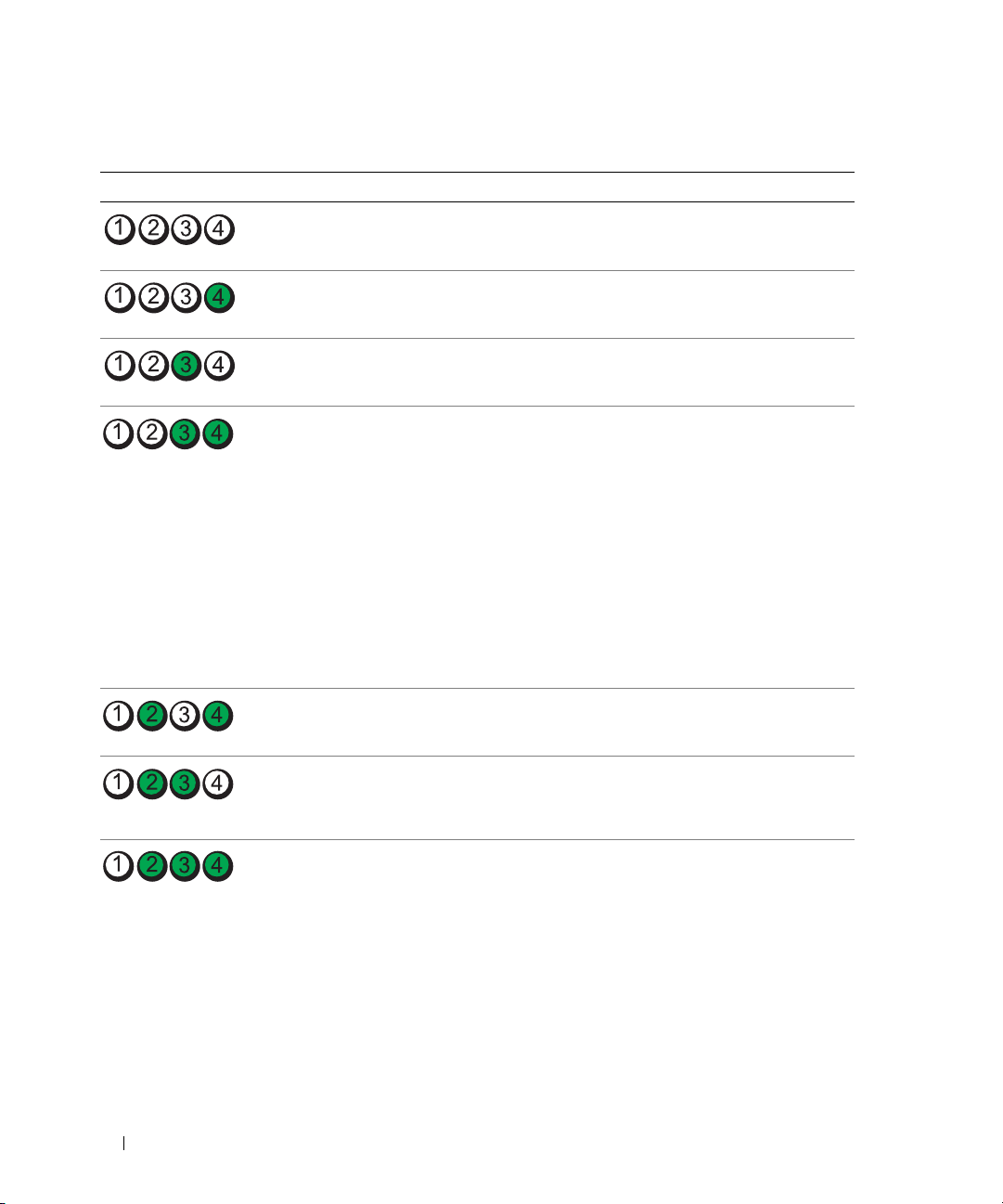
Diagnostic Lights
Light Pattern Problem Description Suggested Resolution
The computer is in a normal condition or
a possible pre-POST failure has occurred.
The computer is in recovery mode. None.
A possible processor failure was detected. Contact Dell (see "Contacting Dell" on
See "Power Light" on page 47.
page 108).
Memory modules are detected, but a
memory failure has occurred.
A possible graphics failure has occurred. If the problem persists, contact Dell (see
A possible floppy drive or hard drive failure
has occurred.
A possible USB failure has occurred. Reinstall all USB devices, check cable
• If you have two or more memory
modules installed, remove the modules,
reinstall one module (see "Memory" on
page 64), and then restart the computer.
If the computer starts normally, reinstall
an additional module. Continue until
you have identified a faulty module or
reinstalled all modules without error.
• If available, install properly working
memory of the same type into your
computer (see "Memory" on page 64).
• If the problem persists, contact Dell
(see
"Contacting Dell" on page 108
"Contacting Dell" on page 108).
Reseat all power and data cables and
restart the computer.
connections, and then restart the
computer.
).
48 Advanced Troubleshooting
Page 49
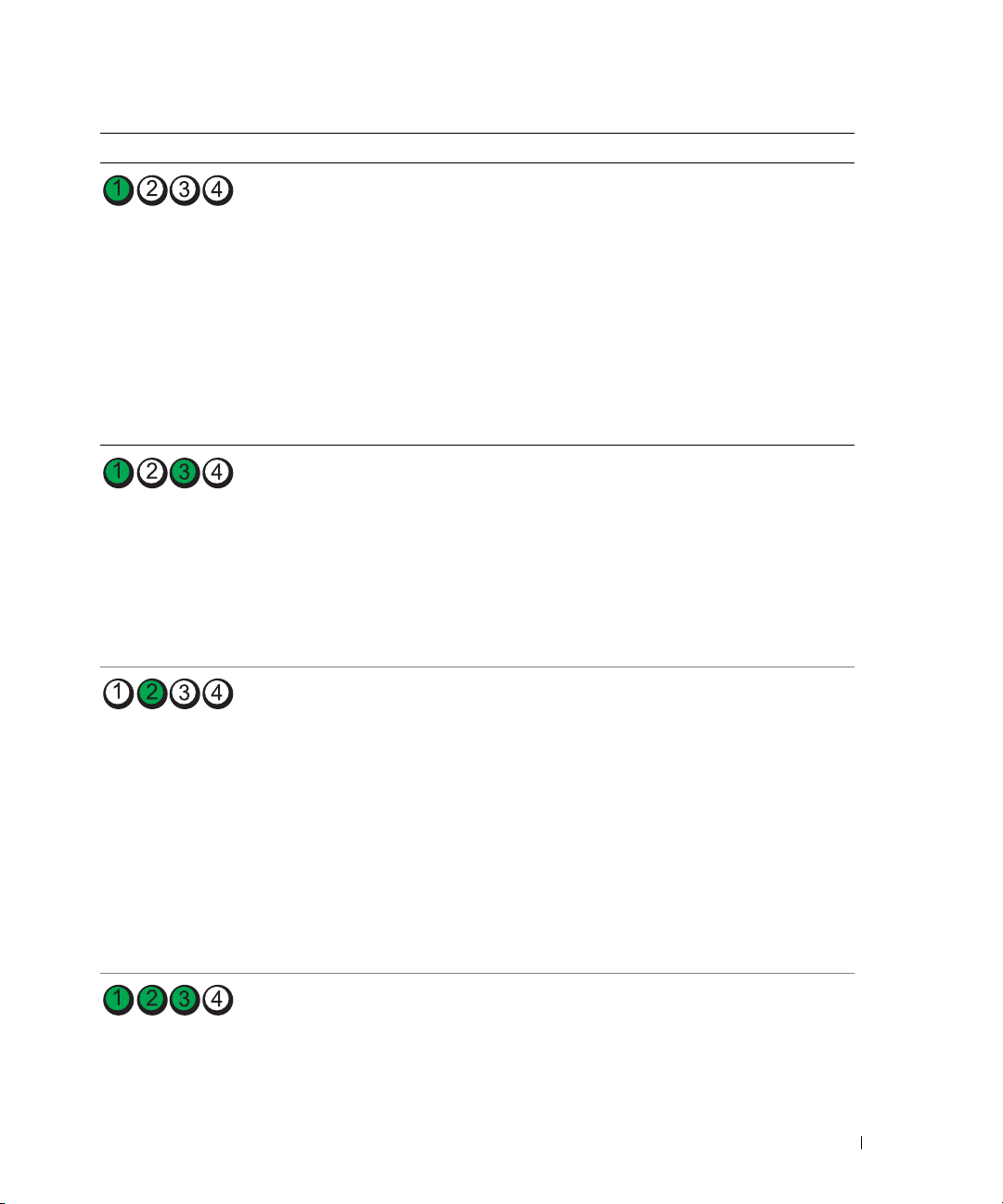
Light Pattern Problem Description Suggested Resolution
No memory modules are detected.
• If you have two or more memory
modules installed, remove the modules,
reinstall one module (see "Memory" on
page 64), and then restart the computer.
If the computer starts normally, reinstall
an additional module. Continue until
you have identified a faulty module or
reinstalled all modules without error.
• If available, install properly working
memory of the same type into your
computer (see "Memory" on page 64).
• If the problem persists, contact Dell
"Contacting Dell" on page 108
(see
Memory modules are detected, but a
memory configuration or compatibility
error exists.
• Ensure that no special memory
module/memory connector placement
requirements exist (see "Memory" on
page 64).
• Verify that the memory modules that
you are installing are compatible with
your computer (see "Memory" on
page 64).
• If the problem persists, contact Dell
(see
"Contacting Dell" on page 108).
A possible expansion card failure has
occurred.
1
Determine whether a conflict exists by
removing a card and restarting the
computer (see "Cards" on page 68).
2
If the problem persists, reinstall the card
that you removed, remove a different
card, and then restart the computer.
3
Repeat this process for each card. If the
computer starts normally, troubleshoot
the last card removed from the
computer for resource conflicts (see
"Resolving Software and Hardware
Incompatibilities" on page 54).
4
If the problem persists, contact Dell
(see
"Contacting Dell" on page 108
Routine system activity subsequent to
video initialization.
Watch your monitor for on-screen
messages.
).
).
Advanced Troubleshooting 49
Page 50
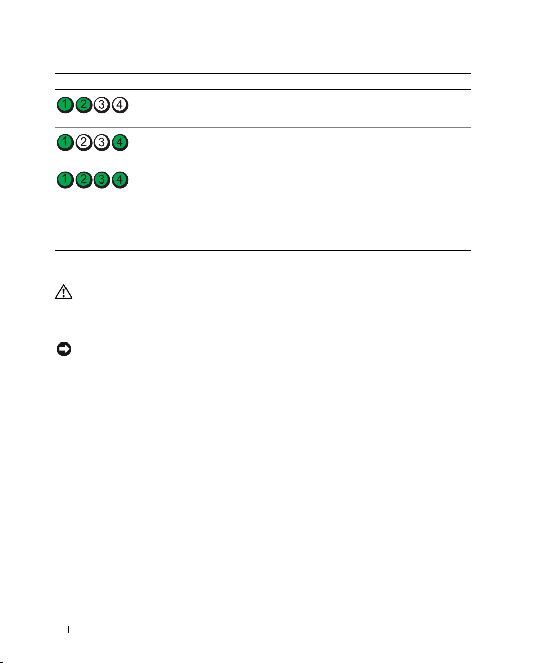
Light Pattern Problem Description Suggested Resolution
System resource configuration in progress. None.
System board failure has occurred.
During normal operation, all of the
diagnostic lights turn on and then turn off
before the system starts.
NOTE: If all of the diagnostic lights are on
and the system does not start, there may be
a problem with the power supply or with the
processor.
Contact Dell
page 108)
If the system does not start, plug the
computer into a working electrical outlet.
Also see "Power Problems" on page 40.
If there are no power problems and the
system does not start, contact Dell (see
"Contacting Dell" on page 108).
(see "Contacting Dell" on
.
Dell Diagnostics
CAUTION: Before you begin any of the procedures in this section, follow the safety instructions located in the
Product Information Guide.
If you experience a problem with your computer, perform the checks in "Solving Problems" on page 31
and run the Dell Diagnostics before you contact Dell for technical assistance.
NOTICE: The Dell Diagnostics works only on Dell™ computers.
1
Turn on (or restart) your computer.
2
When the DELL™ logo appears, press <F12> immediately.
If you wait too long and the operating system logo appears, continue to wait until you see the
Microsoft
page 59) and try again.
®
Windows® desktop, then shut down your computer (see "Turning Off Your Computer" on
3
When the boot device list appears, highlight
4
When the Dell Diagnostics
Main Menu" on page 51).
50 Advanced Troubleshooting
Main Menu
Boot to Utility Partition
, then press <Enter>.
appears, select the test you want to run (see "Dell Diagnostics
Page 51
Dell Diagnostics Main Menu
1
After the Dell Diagnostics loads and the
you want.
Option Function
Express Test Performs a quick test of devices. This test typically takes 10 to
20 minutes and requires no interaction on your part. Run
Express Test first to increase the possibility of tracing the
problem quickly.
Extended Test Performs a thorough check of devices. This test typically takes
an hour or more and requires you to answer questions
periodically.
Custom Test Tests a specific device. You can customize the tests you want
to run.
Symptom Tree Lists the most common symptoms encountered and allows you
to select a test based on the symptom of the problem you are
having.
2
If a problem is encountered during a test, a message appears with an error code and a description of the
problem. Write down the error code and problem description and follow the instructions on the
screen.
If you cannot resolve the error condition, contact Dell (see
NOTE: The Service Tag for your computer is located at the top of each test screen. If you contact Dell,
technical support will ask for your Service Tag.
3
If you run a test from the
Custom Test
the following table for more information.
Main Menu
or
Symptom Tree
screen appears, click the button for the option
"Contacting Dell" on page 108
).
option, click the applicable tab described in
Tab Function
Results Displays the results of the test and any error conditions
encountered.
Errors Displays error conditions encountered, error codes, and the
problem description.
Help Describes the test and may indicate requirements for running
the test.
Advanced Troubleshooting 51
Page 52

Tab Function
Configuration Displays your hardware configuration for the selected device.
The Dell Diagnostics obtains configuration information for all
devices from system setup, memory, and various internal tests,
and it displays the information in the device list in the left pane
of the screen. The device list may not display the names of all
the components installed on your computer or all devices
attached to your computer.
Parameters Allows you to customize the test by changing the test settings.
4
Close the test screen to return to the
computer, close the
Main Menu
Main Menu
screen.
screen. To exit the Dell Diagnostics and restart the
Drivers
What Is a Driver?
A driver is a program that controls a device such as a printer, mouse, or keyboard. All devices require a
driver program.
A driver acts like a translator between the device and any other programs that use the device. Each device
has its own set of specialized commands that only its driver recognizes.
Dell ships your computer to you with required drivers already installed—no further installation or
configuration is needed.
NOTE: If you reinstall the operating system for your computer, you should reinstall the DSS utility prior to installing
any drivers.
Many drivers, such as the keyboard driver, come with your Microsoft® Windows® operating system. You
may need to install drivers if you:
• Upgrade your operating system.
• Reinstall your operating system.
• Connect or install a new device.
Identifying Drivers
If you experience a problem with any device, identify whether the driver is the source of your problem
and, if necessary, update the driver.
Windows XP
1
Click the
2
Under
3
Click
52 Advanced Troubleshooting
Start
button, then click
Pick a Category
System
.
Control Panel
, click
Performance and Maintenance
.
.
Page 53

4
In the
System Properties
5
Click
Device Manager
6
Scroll down the list to see if any device has an exclamation point (a yellow circle with a [!]) on the
window, click the
.
Hardware
tab.
device icon.
If an exclamation point is next to the device name, you may need to reinstall the driver or install a new
driver.
Reinstalling Drivers
NOTICE: The Dell Support website at support.dell.com provides approved drivers for Dell™ computers. If you
install drivers obtained from other sources, your computer might not work correctly.
Using Windows XP Device Driver Rollback
If a problem occurs on your computer after you install or update a driver, use Windows XP Device Driver
Rollback to replace the driver with the previously installed version.
1
Click the
2
Under
3
Click
4
In the
5
Click
6
Right-click the device for which the new driver was installed, then click
7
Click the
8
Click
If Device Driver Rollback does not resolve the problem, then use System Restore to return your computer to
the operating state that existed before you installed the new driver.
Start
button, then click
Pick a Category
System
.
System Properties
Device Manager
Drivers
tab.
Roll Back Driver
Control Panel
, click
Performance and Maintenance
window, click the
Hardware
.
.
.
.
tab.
Properties
.
Manually Reinstalling Drivers
1
After copying the required driver files to your hard drive, click the
My Computer
2
Click
Properties
3
Click the
4
Double-click the type of device for which you are installing the driver.
5
Double-click the name of the device for which you are installing the driver.
6
Click the
7
Click
Install from a list or specific location (Advanced)
8
Click
Browse
.
.
Hardware
Driver
tab, then click
tab, then click
Device Manager
Update Driver
.
.
, then click
and browse to the location to which you previously extracted the driver files.
Start
button, and then right-click
Next
.
Advanced Troubleshooting 53
Page 54

9
When the name of the appropriate driver appears, click
10
Click
Finish
and restart your computer.
Next
.
Resolving Software and Hardware Incompatibilities
If a device is either not detected during the operating system setup or is detected but incorrectly
configured, you can use the Hardware Troubleshooter to resolve the incompatibility.
To resolve incompatibilities using the Hardware Troubleshooter:
Click the
1
2
Ty p e
3
Click
4
In the
then click
Start
button, then click
hardware troubleshooter
Hardware Troubleshooter
Hardware Troubleshooter
Next
.
Help and Support
in the
list, click
.
in the
Search
field, then click the arrow to start the search.
Search Results
I need to resolve a hardware conflict on my computer
list.
Restoring Your Operating System
You can restore your operating system in the following ways:
• Microsoft Windows XP System Restore returns your computer to an earlier operating state without
affecting data files.
• Dell PC Restore by Symantec restores your hard drive to the operating state it was in when you
purchased the computer. Dell PC Restore permanently deletes all data on the hard drive and removes
any applications installed after you received the computer.
, and
Using Microsoft® Windows® XP System Restore
The Microsoft Windows XP operating system provides System Restore to allow you to return your computer
to an earlier operating state (without affecting data files) if changes to the hardware, software, or other
system settings have left the computer in an undesirable operating state. See the Windows Help and
Support Center for information on using System Restore.
NOTICE: Make regular backups of your data files. System Restore does not monitor your data files or recover
them.
NOTE: The procedures in this document were written for the Windows default view, so they may not work if you
set your Dell™ computer to the Windows Classic view.
Creating a Restore Point
1
Click the
2
Click
3
Follow the instructions on the screen.
54 Advanced Troubleshooting
Start
button, then click
System Restore
Help and Support
.
.
Page 55

Restoring the Computer to an Earlier Operating State
If problems occur after you install a device driver, use Device Driver Rollback (see "Using Windows XP
Device Driver Rollback" on page 53) to resolve the problem. If that is unsuccessful, then use System
Restore.
NOTICE: Before you restore the computer to an earlier operating state, save and close any open files and exit any
open programs. Do not alter, open, or delete any files or programs until the system restoration is complete.
1
Click the
Restore
2
Ensure that
3
Click a calendar date to which you want to restore your computer.
The
Start
button, point to
.
Restore my computer to an earlier time
Select a Restore Point
All Programs→
Accessories→
System Tools
is selected, then click
, and then click
Next
.
System
screen provides a calendar that allows you to see and select restore points.
All calendar dates with available restore points appear in boldface type.
4
Select a restore point, then click
Next
.
If a calendar date has only one restore point, then that restore point is automatically selected. If two or
more restore points are available, click the restore point that you prefer.
5
Click
Next
.
The
Restoration Complete
screen appears after System Restore finishes collecting data and then the
computer restarts.
6
After the computer restarts, click OK.
To change the restore point, you can either repeat the steps using a different restore point, or you can undo
the restoration.
Undoing the Last System Restore
NOTICE: Before you undo the last system restore, save and close all open files and exit any open programs. Do not
alter, open, or delete any files or programs until the system restoration is complete.
1
Click the
Restore
2
Click
Enabling System Restore
Start
button, point to
.
Undo my last restoration
All Programs→ Accessories→ System Tools
, then click
Next
.
, and then click
System
If you reinstall Windows XP with less than 200 MB of free hard-disk space available, System Restore is
automatically disabled. To see if System Restore is enabled:
1
Click the
2
Click
3
Click
Start
button, then click
Control Panel
Performance and Maintenance
System
.
.
.
Advanced Troubleshooting 55
Page 56

4
Click the
5
Ensure that
System Restore
tab.
Turn off System Restore
is unchecked.
Using Dell™ PC Restore by Symantec
NOTE: Dell PC Restore is not available in all countries.
Use Dell PC Restore by Symantec only as the last method to restore your operating system. PC Restore
restores your hard drive to the operating state it was in when you purchased the computer. Any programs or
files added since you received your computer
drive. Data files include documents, spreadsheets, e-mail messages, digital photos, music files, and so on. If
possible, back up all data before using PC Restore.
NOTICE: Using PC Restore permanently deletes all data on the hard drive and removes any applications or drivers
installed after you received your computer. If possible, back up the data before using PC Restore.
To use PC Restore:
1
Turn on the computer and watch the keyboard status lights.
2
Immediately upon seeing the lights flash, press <Ctrl><F11>.
If you do not press <Ctrl><F11> in time, let the computer finish restarting, and then restart the
computer again.
NOTICE: If you do not want to proceed with PC Restore, click Reboot in the following step.
3
On the next screen that appears, click
4
On the next screen, click
Confirm
The restore process takes approximately 6–10 minutes to complete.
.
—
including data files—are permanently deleted from the hard
Restore
.
5
When prompted, click
NOTE: Do not manually shut down the computer. Click Finish and let the computer completely reboot.
6
When prompted, click
The computer restarts. Because the computer is restored to its original operating state, the screens that
appear, such as the End User License Agreement, are the same ones that appeared the first time the
computer was turned on.
7
Click
Next
.
The
System Restore
8
After the computer restarts, click OK.
screen appears and the computer restarts.
56 Advanced Troubleshooting
Finish
to reboot the computer.
Yes
.
Page 57

Removing Dell PC Restore
NOTICE: Removing Dell PC Restore from the hard drive permanently deletes the PC Restore utility from your
computer. After you have removed Dell PC Restore, you will not be able to use it to restore your computer’s
operating system.
Dell PC Restore enables you to restore your hard drive to the operating state it was in when you
purchased your computer. It is recommended that you do not remove PC Restore from your computer,
even to gain additional hard-drive space. If you remove PC Restore from the hard drive, you cannot
retrieve it, and you will not be able to use PC Restore to return your computer’s operating system to its
original state.
To remove PC Restore:
1
Log on to the computer as a local administrator.
2
In Windows Explorer, go to
3
Double-click the filename
NOTE: If you do not log on as a local administrator, a message appears stating that you must log on as
administrator. Click Quit, and then log on as a local administrator.
NOTE: If the partition for PC Restore does not exist on your computer’s hard drive, a message appears stating
that the partition was not found. Click Quit; there is no partition to delete.
4
Click OK to remove the PC Restore partition on the hard drive.
5
Click
Yes
when a confirmation message appears.
The PC Restore partition is deleted and the newly available disk space is added to the free space
allocation on the hard drive.
c:\dell\utilities\DSR
DSRIRRemv2.exe
.
.
6
Right-click
Local Disk (C)
in Windows Explorer, click
space is available as indicated by the increased value for
7
Click
Finish
to close the
8
Restart the computer.
PC Restore Removal
window.
Properties
Free Space
, and verify that the additional disk
.
Advanced Troubleshooting 57
Page 58

58 Advanced Troubleshooting
Page 59

Removing and Installing Parts
Before You Begin
This chapter provides procedures for removing and installing the components in your computer.
Unless otherwise noted, each procedure assumes that the following conditions exist:
• You have performed the steps in "Turning Off Your Computer" and "Before Working Inside Your
Computer" on page 60.
• You have read the safety information in your Dell™
NOTE: Unless otherwise noted, a component can be replaced or—if purchased separately—installed by
performing the removal procedure in reverse order.
Recommended Tools
The procedures in this document may require the following tools:
• Small flat-blade screwdriver
• Phillips screwdriver
• Flash BIOS executable update program on
support.dell.com
Turning Off Your Computer
NOTICE: To avoid losing data, save and close any open files and exit any open programs before you turn off
your computer.
1
Shut down the operating system:
a
Save and close any open files, exit any open programs, click the
Turn Off Computer
b
In the
Turn off computer
The computer turns off after the operating system shutdown process finishes.
.
window, click
Turn o f f
Product Information Guide.
Start
button, and then click
.
2
Ensure that the computer and any attached devices are turned off. If your computer and attached
devices did not automatically turn off when you shut down your operating system, press and hold
the power button for 4 seconds.
Removing and Installing Parts 59
Page 60
Before Working Inside Your Computer
Use the following safety guidelines to help protect your computer from potential damage and to help
ensure your own personal safety.
CAUTION: Before you begin any of the procedures in this section, follow the safety instructions located in the
Product Information Guide.
CAUTION: Handle components and cards with care. Do not touch the components or contacts on a card. Hold a
card by its edges or by its metal mounting bracket. Hold a component such as a processor by its edges, not by its
pins.
NOTICE: Only a certified service technician should perform repairs on your computer. Damage due to servicing
that is not authorized by Dell is not covered by your warranty.
NOTICE: When you disconnect a cable, pull on its connector or on its strain-relief loop, not on the cable itself.
Some cables have a connector with locking tabs; if you are disconnecting this type of cable, press in the locking
tabs before you disconnect the cable. As you pull connectors apart, keep them evenly aligned to avoid bending any
connector pins. Also, before you connect a cable, ensure that both connectors are correctly oriented and aligned.
NOTICE: To avoid damaging the computer, perform the following steps before you begin working inside the
computer.
1
Turn off your computer (see "Turning Off Your Computer" on page 59).
NOTICE: To disconnect a network cable, first unplug the cable from your computer and then unplug it from the
network port or device.
2
Disconnect any telephone or telecommunication lines from the computer.
3
Disconnect your computer and all attached devices from their electrical outlets, and then press the
power button to ground the system board.
CAUTION: To guard against electrical shock, always unplug your computer from the electrical outlet before
removing the cover.
4
Remove the computer cover (see "Removing the Computer Cover" on page 60).
NOTICE: Before touching anything inside your computer, ground yourself by touching an unpainted metal surface,
such as the metal at the back of the computer. While you work, periodically touch an unpainted metal surface to
dissipate any static electricity that could harm internal components.
Removing the Computer Cover
CAUTION: Before you begin any of the procedures in this section, follow the safety instructions located in the
Product Information Guide.
CAUTION: To guard against electrical shock, always unplug your computer from the electrical outlet before
removing the cover.
1
Follow the procedures in "Before You Begin" on page 59.
NOTICE: Ensure that sufficient space exists to support the removed cover—at least 30 cm (1 ft) of desktop space.
60 Removing and Installing Parts
Page 61
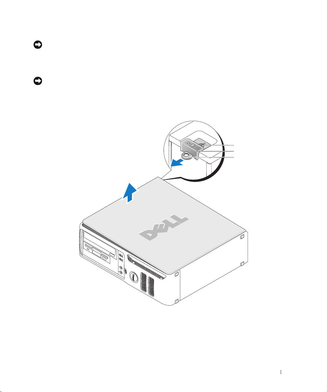
NOTICE: Work on a level, protected surface to avoid scratching either the computer or the surface on which it
rests.
2
If you have installed a padlock through the padlock ring on the back panel, remove the padlock.
3
Lay your computer on its side with the computer cover facing up.
NOTICE: Be careful when opening the computer cover to ensure that you do not accidentally disconnect cables
from the system board.
4
Slide the cover release latch back and lift the cover.
5
Remove the cover and set it aside on a soft nonabrasive surface.
1
2
3
1
security cable slot
2
cover release latch
3
padlock ring
Removing and Installing Parts 61
Page 62
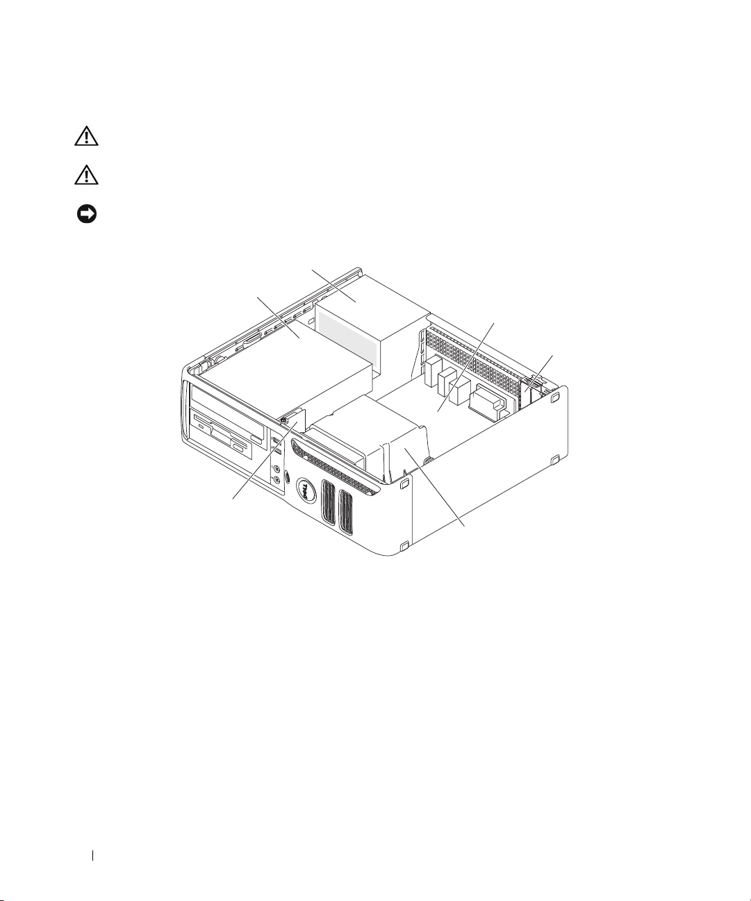
Inside View of Your Computer
CAUTION: Before you begin any of the procedures in this section, follow the safety instructions located in the
Product Information Guide.
CAUTION: To avoid electrical shock, always unplug your computer from the electrical outlet before removing
the computer cover.
NOTICE: Be careful when opening the computer cover to ensure that you do not accidentally disconnect cables
from the system board.
2
1
3
4
6
5
1 drives bay (CD/DVD, floppy,
and hard drive)
4 card slots 5 heat sink assembly 6 front I/O panel
2 power supply 3 system board
62 Removing and Installing Parts
Page 63
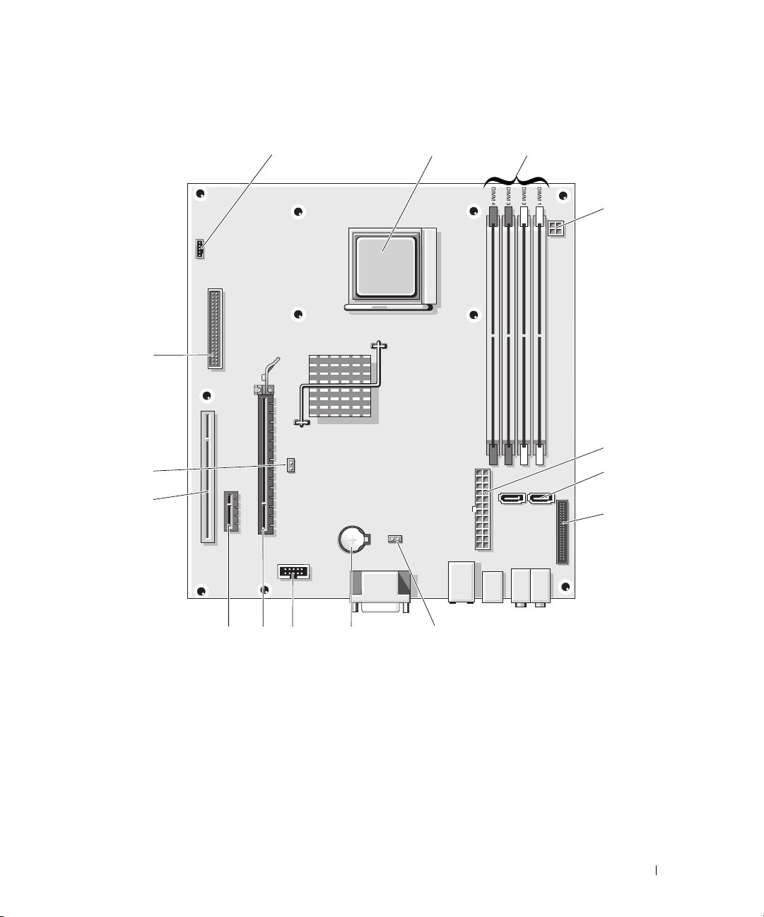
System Board Components
12
15
14
13
3
4
5
6
7
12
11 10
9
8
Removing and Installing Parts 63
Page 64
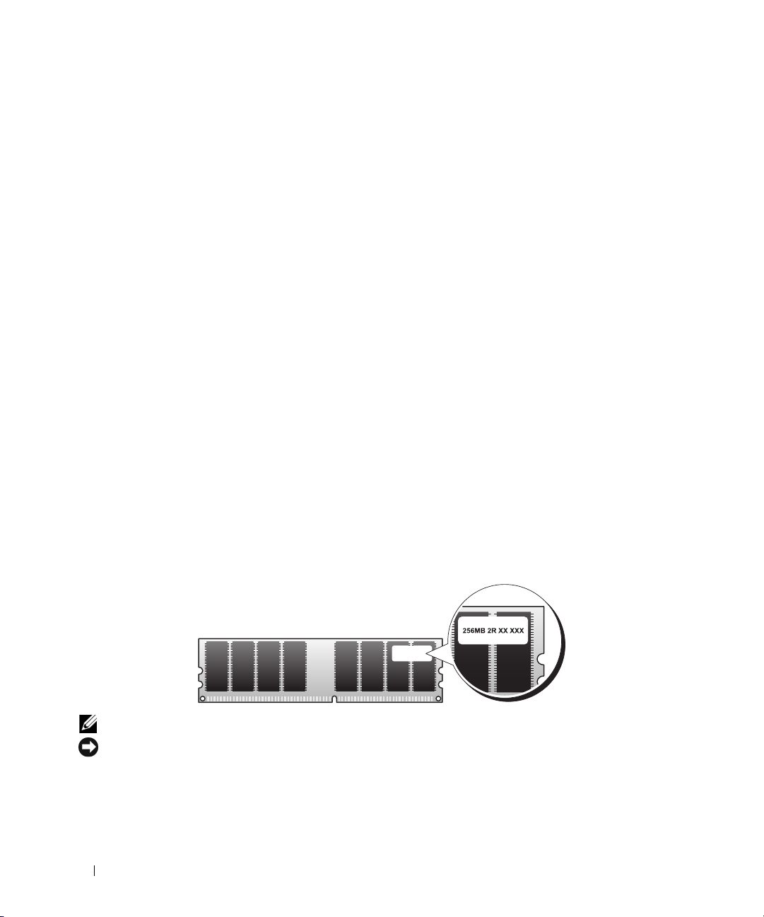
1 fan connector(FAN_CPU1) 2 processor socket (CPU) 3 power connector
(PW_12V_A1)
4 memory module connectors
(DIMM_1, DIMM_2,
DIMM_3, DIMM_4)
7 front-panel connector
(FRONTPANEL)
10 internal USB (USB1) 11 PCI Express x16 connector
13 PCI connector (SLOT3) 14 password jumper (PSWD) 15 floppy drive connector
5 power connector (POWER1) 6 SATA drive connectors
(SATA0, SATA1)
8 CMOS reset (RTCRST) 9 battery socket (BT1)
12 PCI Express x1 connector
(SLOT1)
(SLOT2)
(FLOPPY1)
Memory
If your computer only has one memory module installed on the system board, you can increase your
computer memory by installing an additional memory module.
Your computer supports DDR2 memory. For additional information on the type of memory supported by
your computer, see "Specifications" on page 93.
DDR2 Memory Overview
Your computer has a minimum memory configuration of one DDR2 memory module. This memory
module must be installed in DIMM1. If two or more DDR2 memory modules are installed, they should
be installed in pairs of matched memory size, speed, and technology. If the DDR2 memory modules are not
installed in matched pairs, the computer will continue to operate, but with a slight reduction in
performance. See the label on the module to determine the module’s capacity.
NOTE: Always install DDR2 memory modules in the order indicated on the system board.
NOTICE: Do not install ECC or buffered memory modules. Only unbuffered, non-ECC memory is supported.
The recommended memory configurations are:
• A memory module installed in connector DIMM1
• A pair of matched memory modules installed in connectors DIMM1 and DIMM2
64 Removing and Installing Parts
Page 65
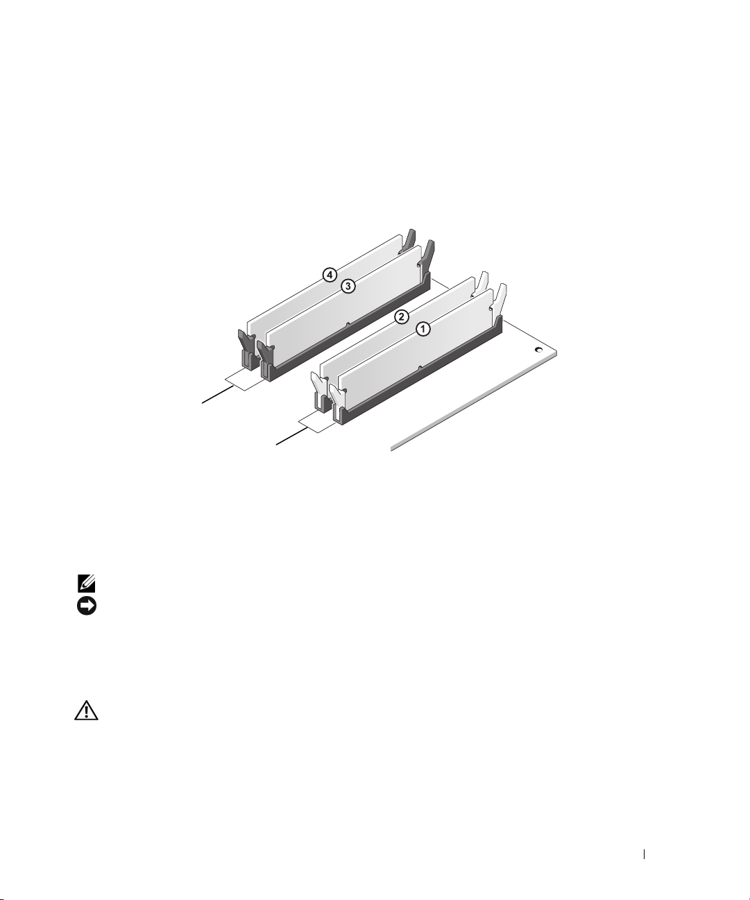
• A pair of matched memory modules installed in connectors DIMM1 and DIMM2 and another
matched pair installed in connectors DIMM3 and DIMM4
• If you install mixed pairs of DDR2 533-MHz (PC2-4300) and DDR2 667-MHz (PC2-5400) memory,
the modules function at the slower installed speed.
Be sure to populate the memory modules in order starting with DIMM1, the connector closest to the
edge of the system board, before you install modules in the other connectors.
2
1
1 Channel A: matched pair of
memory modules in
connectors DIMM_1 and
DIMM_2 (white securing
clips)
NOTE: Memory purchased from Dell is covered under your computer warranty.
NOTICE: If you remove your original memory modules from the computer during a memory upgrade, keep them
separate from any new modules that you may have, even if you purchased the new modules from Dell. If possible,
do not pair an original memory module with a new memory module. Otherwise, your computer may not start
properly.
2 Channel B: matched pair of
memory modules in
connectors DIMM_3 and
DIMM_4 (black securing clips)
Installing Memory
CAUTION: Before you begin any of the procedures in this section, follow the safety instructions located in the
Product Information Guide.
Removing and Installing Parts 65
Page 66
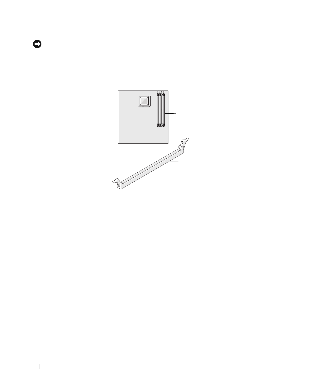
NOTICE: To prevent static damage to components inside your computer, discharge static electricity from your
body before you touch any of your computer’s electronic components. You can do so by touching an unpainted
metal surface on the computer chassis.
1
Follow the procedures in "Before You Begin" on page 59.
2
Press out the securing clip at each end of the memory module connector.
1
2
3
1
memory connector closer to
edge of board
2
securing clips (2)
3
connector
66 Removing and Installing Parts
Page 67
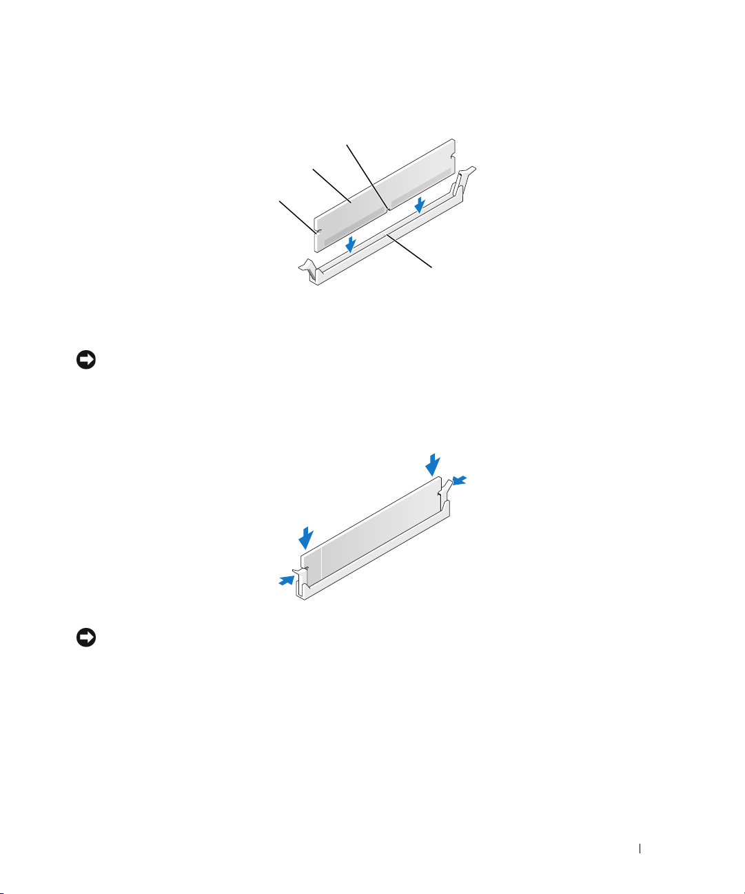
3
Align the notch on the bottom of the module with the crossbar in the connector.
3
2
1
4
1
cutouts (2)
4
crossbar
NOTICE: To avoid damage to the memory module, press the module straight down into the connector while you
apply equal force to each end of the module.
4
Insert the module into the connector until the module snaps into position.
2
memory module
3
notch
If you insert the module correctly, the securing clips snap into the cutouts at each end of the module.
5
Replace the computer cover (see "Replacing the Computer Cover" on page 90).
NOTICE: To connect a network cable, first plug the cable into the network port or device, and then plug it into the
computer.
6
Connect your computer and devices to electrical outlets, and then turn them on.
7
When a message appears stating that memory size has changed, press <F1> to continue.
8
Log on to your computer.
9
Right-click the
10
Click the
11
To verify that the memory is installed correctly, check the amount of memory (RAM) listed.
My Computer
General
tab.
icon, then click
Properties
.
Removing and Installing Parts 67
Page 68

Removing Memory
CAUTION: Before you begin any of the procedures in this section, follow the safety instructions located in the
Product Information Guide.
NOTICE: To prevent static damage to components inside your computer, discharge static electricity from your
body before you touch any of your computer’s electronic components. You can do so by touching an unpainted
metal surface on the computer chassis.
1
Follow the procedures in "Before You Begin" on page 59.
2
Press out the securing clip at each end of the memory module connector.
3
Grasp the module and pull up.
If the module is difficult to remove, gently ease the module back and forth to remove it from the
connector.
4
Replace the computer cover (see "Replacing the Computer Cover" on page 90).
NOTICE: To connect a network cable, first plug the cable into the network port or device, and then plug it into the
computer.
5
Connect your computer and devices to electrical outlets, and then turn them on.
Cards
CAUTION: Before you begin any of the procedures in this section, follow the safety instructions located in the
Product Information Guide.
NOTICE: To prevent static damage to components inside your computer, discharge static electricity from your
body before you touch any of your computer’s electronic components. You can do so by touching an unpainted
metal surface on the computer chassis.
Your Dell™ computer provides the following slots for PCI and PCI Express cards:
• One low-profile PCI card slot
• One low-profile PCI Express x1 and x16 card slot
68 Removing and Installing Parts
Page 69
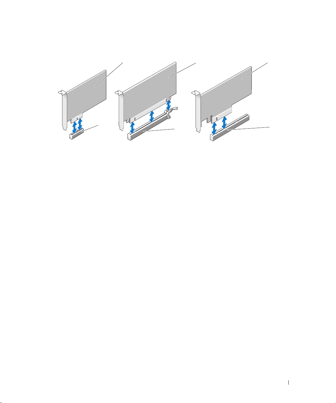
1
2
3
4
1 PCI Express x1 card 2 PCI Express x16 card 3 PCI
4 PCI Express x1 card slot 5 PCI Express x16 card slot 6 PCI card slot
5
6
If you are installing or replacing an expansion card, follow the procedures in the next section. If you are
removing and not replacing an expansion card, see "Removing an Expansion Card" on page 73.
If you are replacing a card with a different type of card, remove the current driver for the card from the
operating system.
Installing an Expansion Card
1
Follow the procedures in "Before You Begin" on page 59.
2
Gently push the release tab on the inside of the card retention door to pivot the door open. Because
the door is captive, it will remain in the open position.
3
If you are installing a new card, remove the filler bracket to create a card-slot opening, then continue
with step 5.
Removing and Installing Parts 69
Page 70
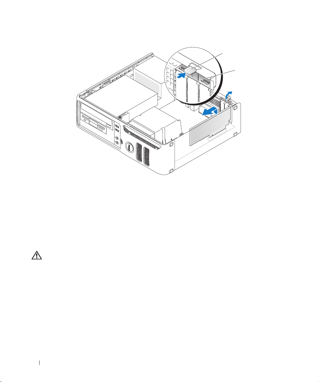
1
2
1 release tab 2 card retention door
4
If you are replacing a card that is already installed in the computer, remove the card.
If necessary, disconnect any cables connected to the card. Grasp the card by its top corners, and ease it
out of its connector.
5
Prepare the card for installation.
See the documentation that came with the card for information on configuring the card, making
internal connections, or otherwise customizing it for your computer.
CAUTION: Some network adapters automatically start the computer when they are connected to a network. To
guard against electrical shock, be sure to unplug your computer from its electrical outlet before installing any
cards.
6
Place the card in the connector and press down firmly. Ensure that the card is fully seated in the slot.
70 Removing and Installing Parts
Page 71
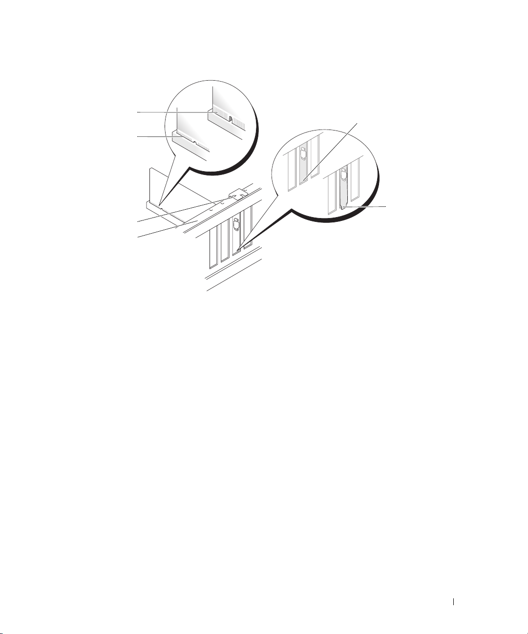
6
5
4
3
1 bracket within slot 2 bracket caught outside of slot 3 alignment bar
4 alignment guide 5 fully seated card 6 not fully seated card
7
Before you close the card retention door, ensure that:
1
2
• The tops of all cards and filler brackets are flush with the alignment bar.
• The notch in the top of the card or filler bracket fits around the alignment guide.
Removing and Installing Parts 71
Page 72
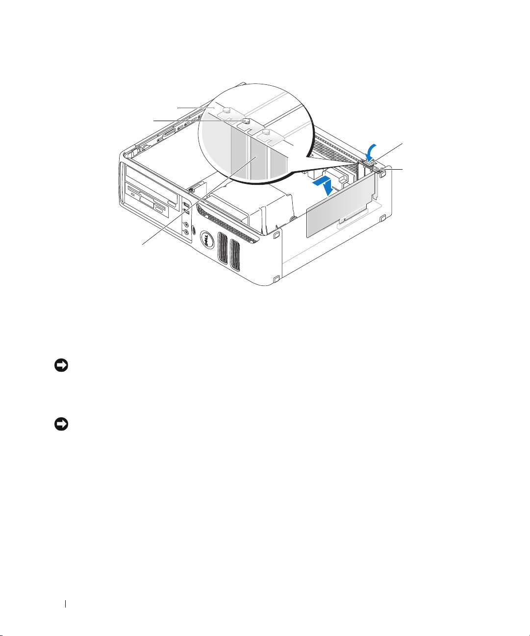
5
4
1
2
3
1 release tab 2 card retention door 3 filler bracket
4 alignment guide 5 alignment bar
8
Close the card retention door by snapping it into place.
NOTICE: Do not route card cables over the cards. Cables routed over the cards can prevent the computer cover
from closing properly or cause damage to the equipment.
9
Connect any cables that should be attached to the card.
See the documentation for the card for information about the card’s cable connections.
NOTICE: To connect a network cable, first plug the cable into the network port or device, and then plug it into the
computer.
10
Replace the computer cover, reconnect the computer and devices to electrical outlets, and then turn
them on.
11
If you installed a sound card:
a
Enter system setup, select
Off
setting to
b
Connect external audio devices to the sound card’s connectors. Do not connect external audio
(see "System Setup Options" on page 98).
Integrated Audio
from the
Onboard Devices
group, and change the
devices to the line-in connector on the back panel of the computer. See "Back Panel I/O
Connectors" on page 16.
72 Removing and Installing Parts
Page 73
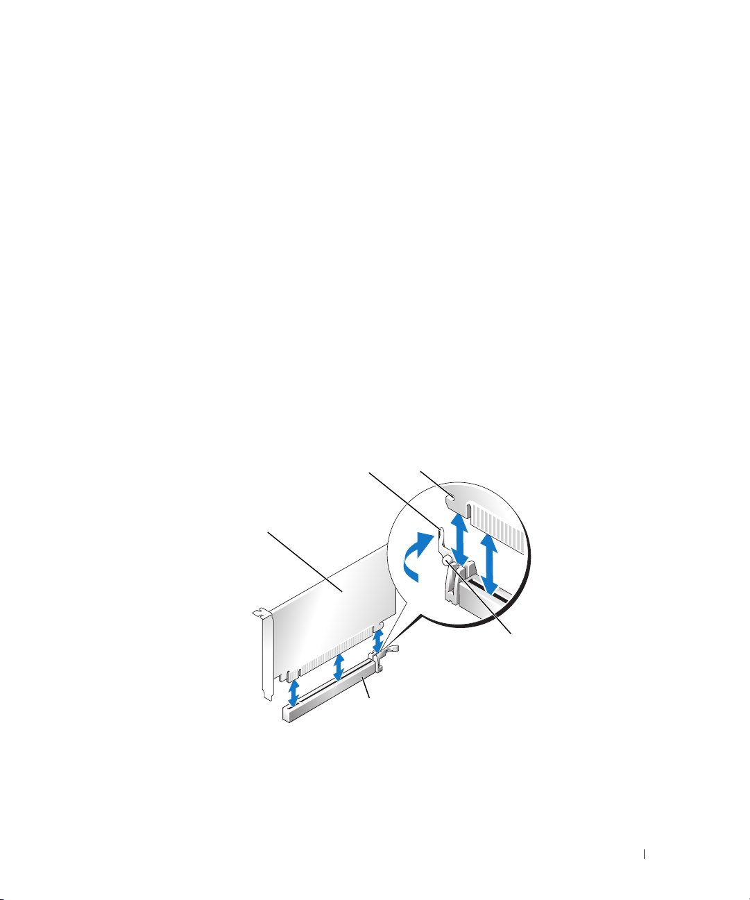
12
If you installed an add-in network adapter and want to disable the integrated network adapter:
a
Enter system setup, select
Off
setting to
b
Connect the network cable to the network adapter card’s connectors. Do not connect the network
(see "System Setup Options" on page 98).
Integrated NIC
from the
Onboard Devices
group, and change the
cable to the integrated network connector on the back panel of the computer.
13
Install any drivers required for the card as described in the card documentation.
Removing an Expansion Card
1
Follow the procedures in "Before You Begin" on page 59.
2
Gently push the release tab on the card retention door from the inside to pivot the door open. Because
the door is captive, it will remain in the open position.
3
If necessary, disconnect any cables connected to the card.
4
Remove the card:
If you are removing a PCI or PCI Express x1 card, grasp the card by its top corners and ease it out of its
connector. Then go to step 6.
If you are removing a PCI Express x16 card, go to step 5.
5
While pressing the lever, pull the card up and out of the card connector.
2
1
5
1 PCI Express x16 card 2 lever 3 securing slot
4 securing tab 5 PCI Express x16 card
connector
3
4
Removing and Installing Parts 73
Page 74

6
If you are removing the card permanently, install a filler bracket in the empty card-slot opening.
NOTE: Installing filler brackets over empty card-slot openings is necessary to maintain FCC certification of the
computer. The brackets also keep dust and dirt out of your computer.
7
Before you close the card retention door, ensure that:
• The tops of all cards and filler brackets are flush with the alignment bar.
• The notch in the top of the card or filler bracket fits around the alignment guide.
8
Close the card retention door by snapping it into place to secure the cards.
NOTICE: To connect a network cable, first plug the cable into the network port or device, and then plug it into the
computer.
9
Replace the computer cover, reconnect the computer and devices to electrical outlets, and then turn
them on.
10
Remove the card’s driver from the operating system.
11
If you removed a sound card:
a
Enter system setup, select
setting to
b
Connect external audio devices to the audio connectors on the back panel of the computer. See
On
(see "System Setup Options" on page 98).
Integrated Audio
from the
Onboard Devices
group, and change the
"Back Panel I/O Connectors" on page 16.
12
If you removed an add-in network connector:
a
Enter system setup, select
On
setting to
b
Connect the network cable to the integrated connector on the back panel of the computer.
(see "System Setup Options" on page 98).
Integrated NIC
from the
Onboard Devices
group, and then change the
74 Removing and Installing Parts
Page 75
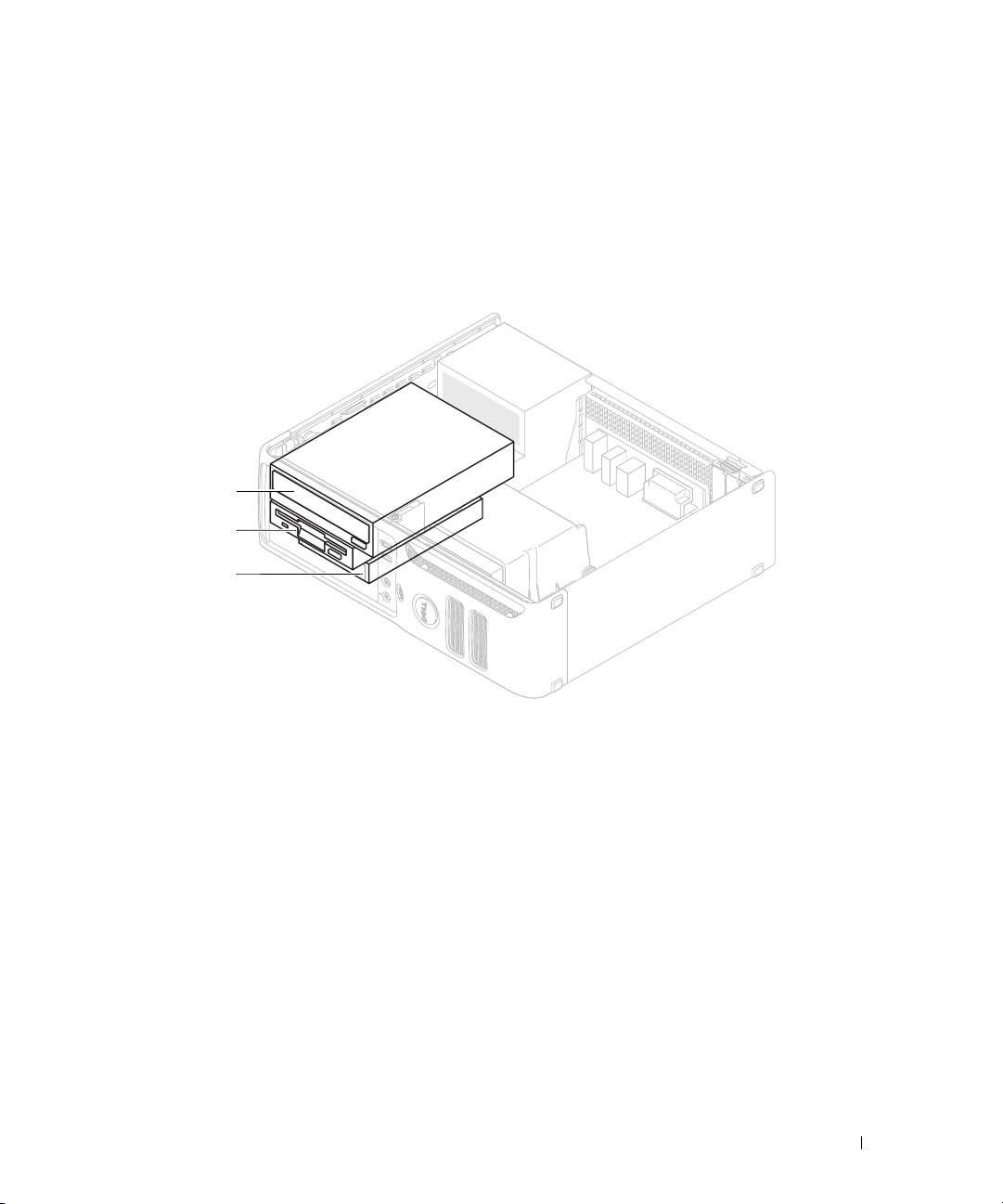
Drives
Your computer supports a combination of these devices:
• One serial ATA hard drive
• One optional floppy drive or Media Card Reader
• One CD or DVD drive
1
2
3
1 DVD drive 2 optional floppy drive or
media card reader
3 hard drive
General Installation Guidelines
Connect the SATA hard drive to the connector labeled "SATA0." Connect the SATA CD or DVD drives
to the connector labeled "SATA1" on the system board. See "System Board Components" on page 63 for
information about system board connectors.
Connecting Drive Cables
When you install a drive, you connect two cables—a DC power cable and a data cable—to the back of
the drive and to the system board.
Removing and Installing Parts 75
Page 76
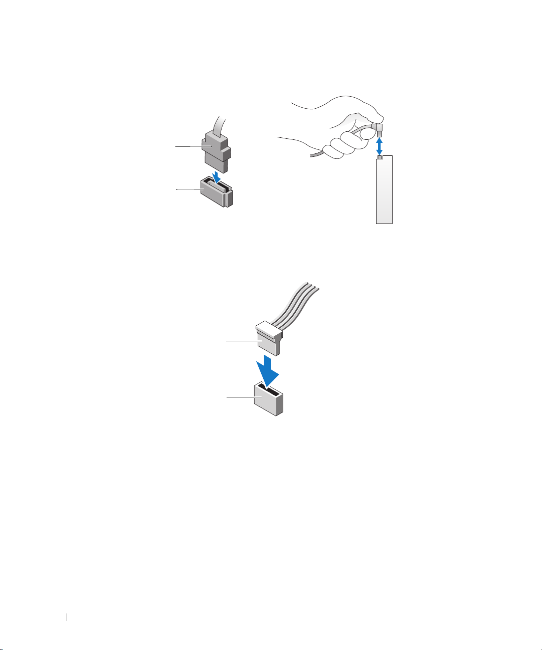
Drive Interface Connectors
Serial ATA Connector
1 interface cable 2 interface connector
Power Cable Connector
1
2
1
2
1 power cable 2 power input connector
Connecting and Disconnecting Drive Cables
When removing a serial ATA data cable, grasp the colored pull tab and pull until the connector detaches.
When connecting a serial ATA data cable, hold the cable by the black connector at each end.
76 Removing and Installing Parts
Page 77
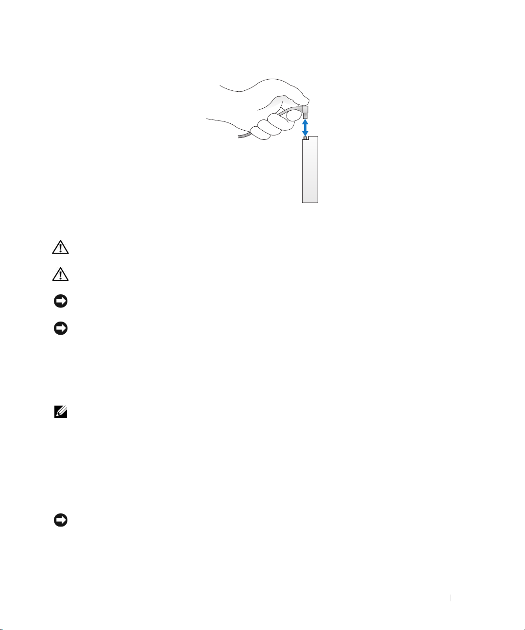
Hard Drive
CAUTION: Before you begin any of the procedures in this section, follow the safety instructions located in the
Product Information Guide.
CAUTION: To guard against electrical shock, always unplug your computer from the electrical outlet before
removing the cover.
NOTICE: To avoid damage to the drive, do not set it on a hard surface. Instead, set the drive on a surface, such as
a foam pad, that will sufficiently cushion it.
NOTICE: If you are replacing a hard drive that contains data you want to keep, back up your files before you begin
this procedure.
Check the documentation for the drive to verify that it is configured for your computer.
Removing a Hard Drive
1
Follow the procedures in "Before You Begin" on page 59.
NOTE: In the following steps it is not necessary to disconnect the cables connecting the CD/DVD or floppy drive or
the Media Card Reader, as long as it does not obstruct your working area once it is set aside.
2
Remove the CD/DVD drive (if installed) from the bay and carefully set it aside (see "Removing a
CD/DVD Drive" on page 87).
3
Remove the floppy drive or Media Card Reader (if installed) from the bay and carefully set it aside (see
"Removing a Media Card Reader" on page 84 or "Removing a Floppy Drive" on page 81).
4
Press in on the two plastic securing clips on each side of the drive and slide the drive towards the back
of the computer.
NOTICE: Do not pull the drive out of the computer by the drive cables. Doing so may cause damage to the cables
and the cable connectors.
5
Lift the drive out of the computer and disconnect the power and data cables from the drive.
Removing and Installing Parts 77
Page 78
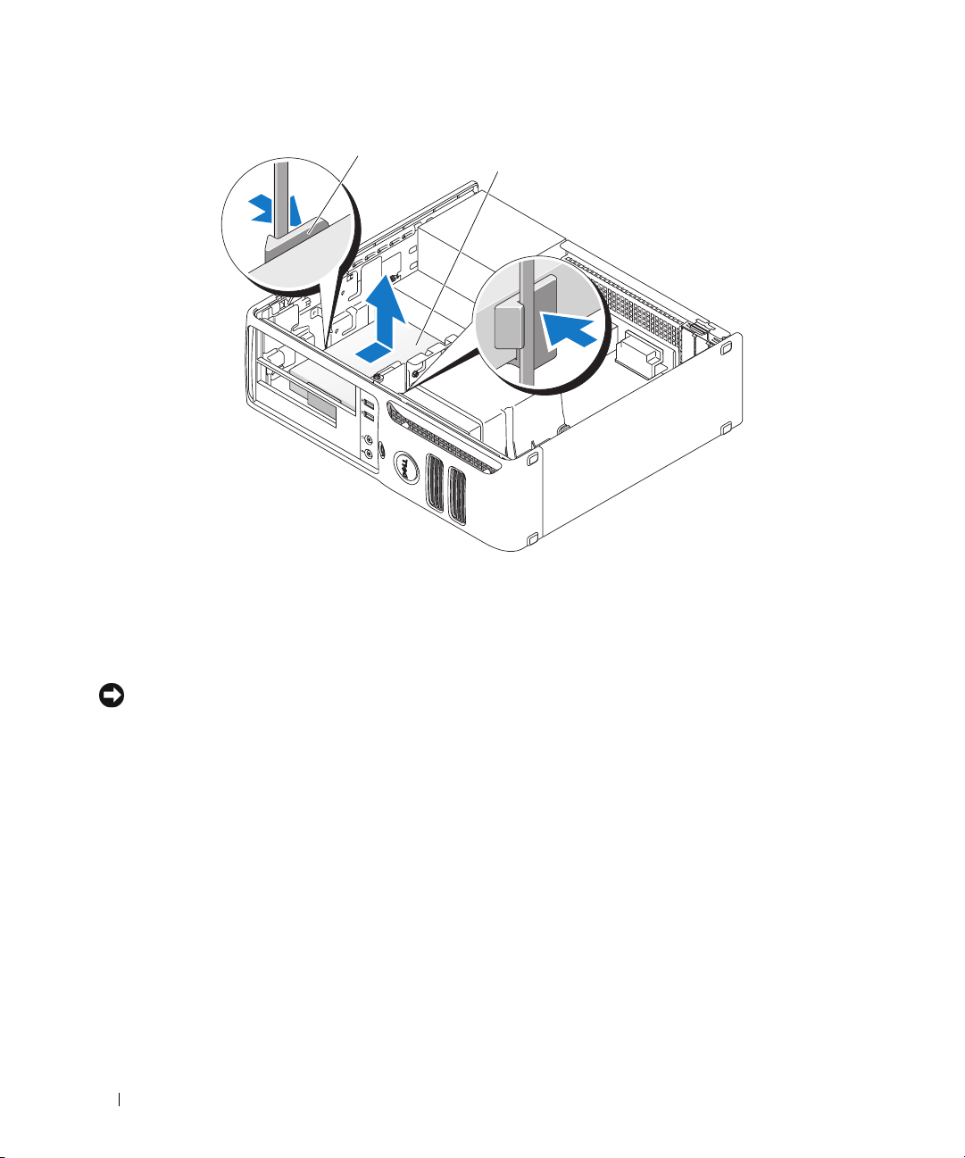
1
2
1 securing clips (2) 2 hard drive
Installing a Hard Drive
1
Check the documentation for the drive to verify that it is configured for your computer.
NOTICE: To avoid damage to the drive, do not set it on a hard surface. Instead, set the drive on a surface, such as
a foam pad, that will sufficiently cushion it.
2
Unpack the replacement hard drive, and prepare it for installation.
78 Removing and Installing Parts
Page 79
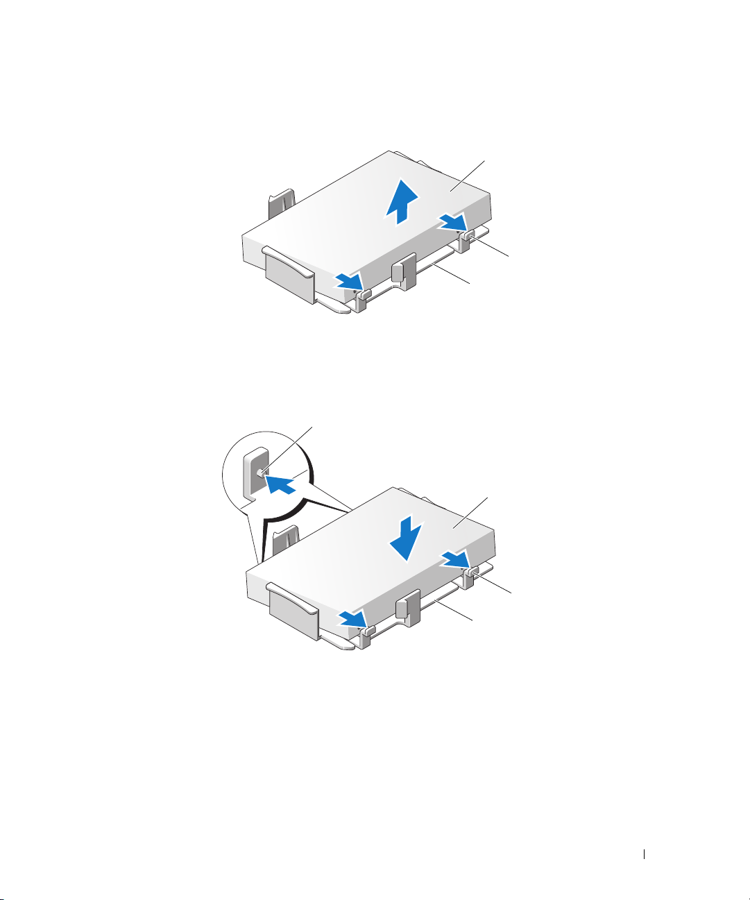
3
1
1
If your replacement hard drive does not have the plastic hard-drive bracket attached, remove the
bracket from the existing drive by unsnapping it from the drive.
2
3
1 hard drive 2 release tabs (2) 3 plastic hard-drive bracket
4
Attach the bracket to the new drive by aligning the two securing tabs with the mounting holes in the
hard drive and then rotating the drive down snapping it onto the bracket.
2
3
4
1 securing tabs (2) 2 hard drive 3 release tabs (2)
4 plastic hard-drive bracket
Removing and Installing Parts 79
Page 80
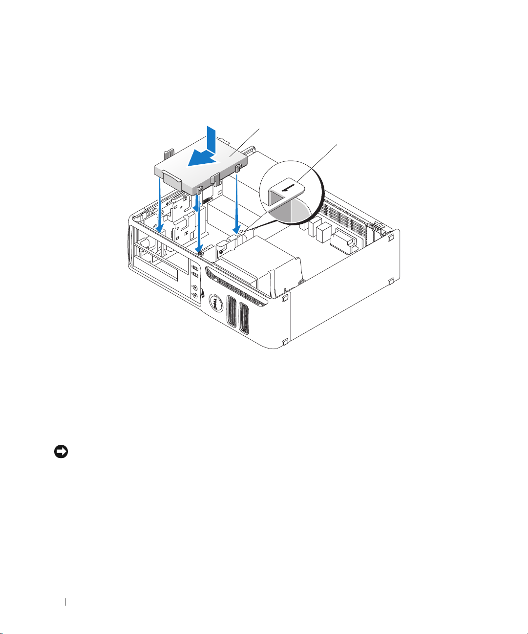
5
Connect the power and data cables to the drive.
6
Locate the correct guidance-slot for the drive (slot 1) and align the release tabs with the alignment
guides.
1
2
1 hard drive 2 slot verification number
7
Slide the drive into the bay until it clicks into place.
8
Replace any drives or readers that you removed.
9
Check all connectors to ensure that they are properly cabled and firmly seated.
10
Replace the computer cover (see "Replacing the Computer Cover" on page 90).
NOTICE: To connect a network cable, first plug the cable into the network port or device, and then plug it into the
computer.
11
Connect your computer and devices to electrical outlets, and then turn them on.
12
If the drive that you installed is the primary drive, insert bootable media into your boot drive.
13
Enter system setup (see "Entering System Setup" on page 97) and update the appropriate
option (0 or 2).
Drive
14
Exit system setup, and reboot the computer.
15
Partition and logically format your drive before you proceed to the next step.
For instructions, see the documentation that came with your operating system.
80 Removing and Installing Parts
Primary
Page 81
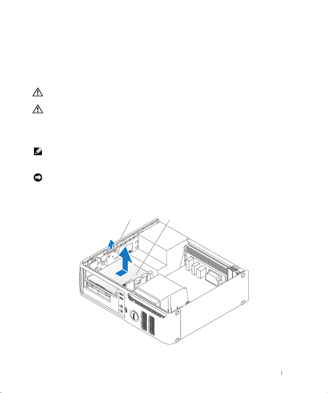
16
Test the hard drive by running the Dell Diagnostics (see "Dell Diagnostics" on page 50).
17
Install your operating system on the hard drive. For instructions, see the documentation that came
with your operating system
Floppy Drive
CAUTION: Before you begin any of the procedures in this section, follow the safety instructions located in the
Product Information Guide.
CAUTION: To guard against electrical shock, always unplug your computer from the electrical outlet before
removing the cover.
Removing a Floppy Drive
1
Follow the procedures in "Before You Begin" on page 59.
NOTE: It is not necessary to disconnect the cables connected to the CD/DVD drive in the following step, as long as
the cables do not obstruct your working area once the drive is set aside.
2
Remove the CD/DVD drive (see "Removing a CD/DVD Drive" on page 87) and carefully set it aside.
NOTICE: Do not pull the drive out of the computer by the drive cables. Doing so may cause damage to the cables
and cable connectors.
3
Pull up on the drive release latch and slide the floppy drive towards the back of the computer. Then, lift
up to remove the drive from the computer.
12
1 drive release latch 2 floppy drive
Removing and Installing Parts 81
Page 82
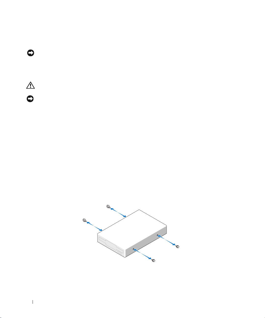
4
Disconnect the power and data cables from the back of the floppy drive.
5
Replace the computer cover (see "Replacing the Computer Cover" on page 90).
NOTICE: To connect a network cable, first plug the cable into the network port or device, and then plug it into the
computer.
6
Connect your computer and devices to electrical outlets, and turn them on.
Installing a Floppy Drive
CAUTION: Before you begin any of the procedures in this section, follow the safety instructions located in the
Product Information Guide.
NOTICE: To prevent static damage to components inside your computer, discharge static electricity from your
body before you touch any of your computer’s electronic components. You can do so by touching an unpainted
metal surface on the computer chassis.
1
Follow the procedures in "Before You Begin" on page 59.
2
Remove the floppy drive and bracket from its packaging.
3
If you are installing a new drive:
a
Remove the drive-panel insert that blocks the FlexBay; gently slide a small flat-edge screwdriver
between the drive-panel insert and the rear of the drive panel until the drive-panel insert pops out
of place.
b
Remove the four shoulder screws from the drive-panel insert.
4
If you are replacing an existing drive:
a
Remove the existing drive.
b
Remove the four shoulder screws from the existing drive.
5
Insert the four shoulder screws into the sides of the new floppy drive and tighten them.
82 Removing and Installing Parts
Page 83
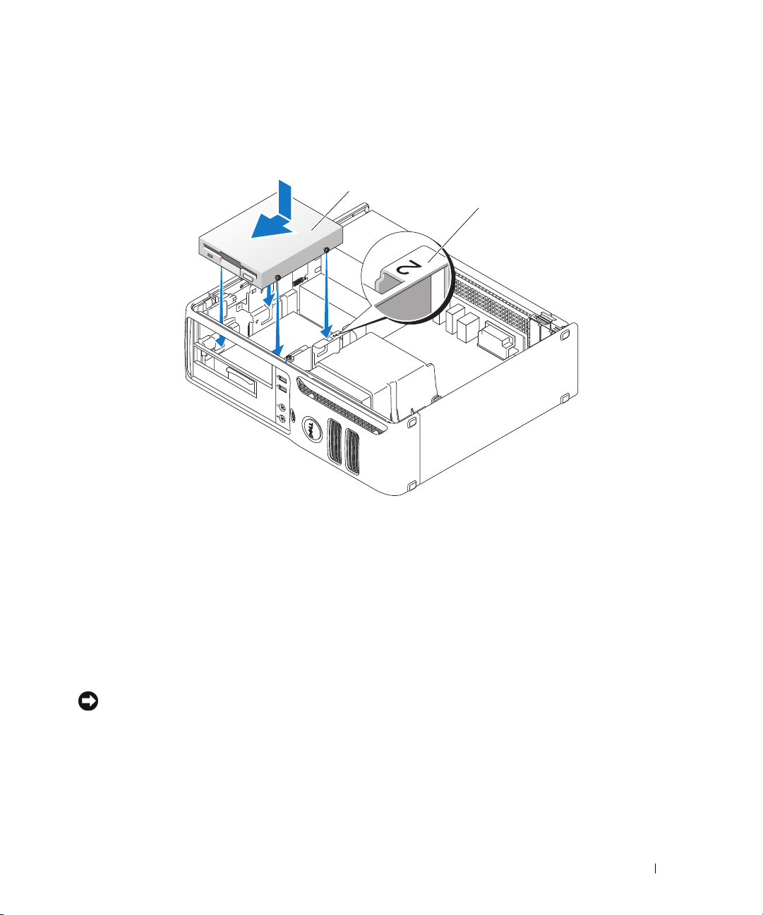
6
Attach the power and data cables to the floppy drive.
7
Locate the correct guidance-slot for the drive (slot 2) and align the shoulder screws with the screw
guides.
1
2
1 floppy drive 2 slot verification number
8
Slide the drive into the bay until it clicks into place.
9
Connect the data cable to the connector labeled "FLOPPY" on the system board (see "System Board
Components" on page 63).
10
Replace the CD/DVD drive.
11
Check all cable connections, and fold cables out of the way to provide airflow for the fan and cooling
vents.
12
Replace the computer cover (see "Replacing the Computer Cover" on page 90).
NOTICE: To connect a network cable, first plug the cable into the network port or device, and then plug it into the
computer.
13
Connect your computer and devices to electrical outlets, and then turn them on.
Media Card Reader
For information about using the Media Card Reader, see "Using a Media Card Reader (Optional)" on
page 24.
Removing and Installing Parts 83
Page 84
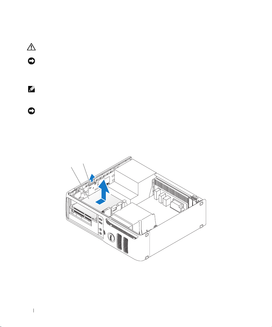
Removing a Media Card Reader
CAUTION: Before you begin any of the procedures in this section, follow the safety instructions located in the
Product Information Guide.
NOTICE: To prevent static damage to components inside your computer, discharge static electricity from your
body before you touch any of your computer’s electronic components. You can do so by touching an unpainted
metal surface on the computer chassis.
1
Follow the procedures in "Before You Begin" on page 59.
NOTE: It is not necessary to disconnect the cables connecting the CD/DVD drive in the following step, as long as
the cables do not obstruct your working area once the drive is set aside.
2
Remove the CD/DVD drive (see "Removing a CD/DVD Drive" on page 87) and carefully set it aside.
NOTICE: Do not pull the drive out of the computer by the drive cables. Doing so may cause damage to the cables
and the cable connectors.
3
Disconnect the Media Card Reader USB cable from the USB connector (USB1) on the system board
(see "System Board Components" on page 63) and route the cable through the clip on the shroud.
4
Pull up on the drive release latch and slide the Media Card Reader towards the back of the computer.
Then, lift up to remove it from the computer.
2
1
1 Media Card Reader 2 drive release latch
5
Replace the computer cover (see "Replacing the Computer Cover" on page 90).
84 Removing and Installing Parts
Page 85
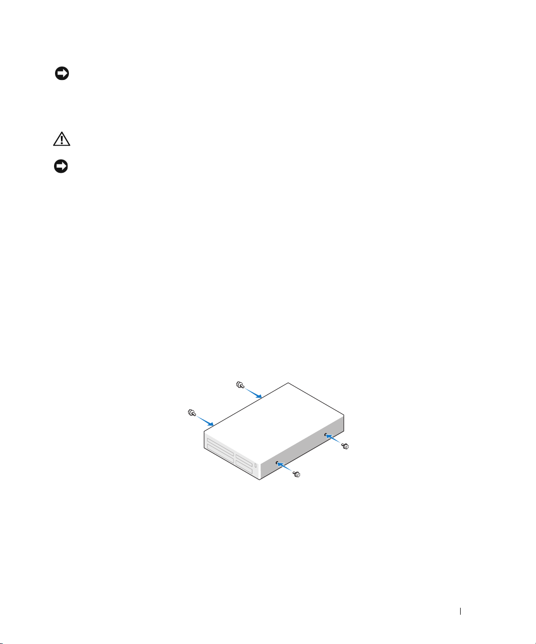
NOTICE: To connect a network cable, first plug the cable into the network port or device, and then plug it into the
computer.
6
Connect your computer and devices to electrical outlets, and then turn them on.
Installing a Media Card Reader
CAUTION: Before you begin any of the procedures in this section, follow the safety instructions located in the
Product Information Guide.
NOTICE: To prevent static damage to components inside your computer, discharge static electricity from your
body before you touch any of your computer’s electronic components. You can do so by touching an unpainted
metal surface on the computer chassis.
1
Follow the procedures in "Before You Begin" on page 59.
2
Remove the Media Card Reader and bracket from its packaging.
3
If you are installing a new Media Card Reader:
a
Remove the drive-panel insert that blocks the FlexBay; gently slide a small flat-edge screwdriver
between the drive-panel insert and the rear of the drive panel until the drive-panel insert pops out
of place.
b
Remove the four shoulder screws from the drive-panel insert.
4
If you are replacing an existing Media Card Reader:
a
Remove the existing Media Card Reader.
b
Remove the four shoulder screws from the existing Media Card Reader.
5
Insert four shoulder screws into the sides of the Media Card Reader and tighten them.
Removing and Installing Parts 85
Page 86
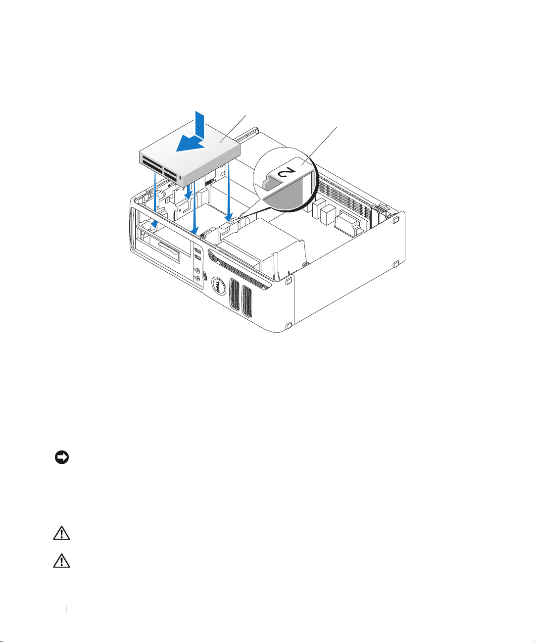
6
Locate the correct guidance-slot for the Media Card Reader (slot 2) and align the shoulder screws with
the screw guides.
1
2
1 Media Card Reader 2 slot verification number
7
Slide the Media Card Reader into the bay until it clicks into place.
8
Connect the power and data cables to the back of the Media Card Reader.
9
Connect the data cable to the USB connector on the system board (see "System Board Components"
on page 63).
10
Replace the computer cover (see "Replacing the Computer Cover" on page 90).
NOTICE: To connect a network cable, first plug the cable into the network port or device, and then plug it into the
computer.
11
Connect your computer and devices to electrical outlets, and then turn them on.
CD/DVD Drive
CAUTION: Before you begin any of the procedures in this section, follow the safety instructions located in the
Product Information Guide.
CAUTION: To guard against electrical shock, always unplug your computer from the electrical outlet before
removing the cover.
86 Removing and Installing Parts
Page 87
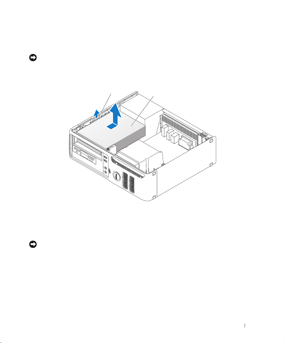
Removing a CD/DVD Drive
1
1
Follow the procedures in "Before You Begin" on page 59.
NOTICE: Do not pull the drive out of the computer by the drive cables. Doing so may cause damage to the cables
and the cable connectors.
2
Pull up on the drive release latch and slide the drive towards the back of the computer. Then, lift up to
remove the drive from the computer.
2
1 drive release latch 2 CD/DVD drive
3
Disconnect the power and data cables from the back of the drive.
4
Replace the computer cover (see "Replacing the Computer Cover" on page 90).
NOTICE: To connect a network cable, first plug the cable into the network port or device, and then plug it into the
computer.
5
Connect your computer and devices to electrical outlets, and then turn them on.
Installing a CD/DVD Drive
1
Follow the procedures in "Before You Begin" on page 59.
2
Unpack the drive and prepare it for installation.
Removing and Installing Parts 87
Page 88
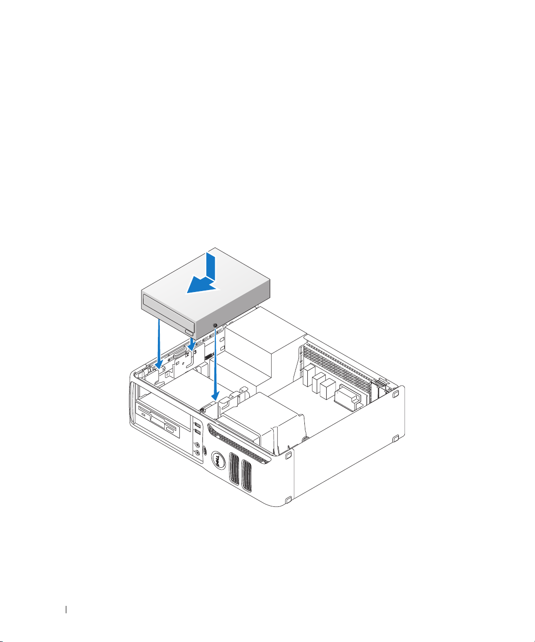
3
If you are installing a new drive:
a
Press the two snaps on the top of the drive-panel insert and rotate the insert toward the front of
the computer. Remove it from the computer.
b
Remove the three shoulder screws from the drive-panel insert.
4
If you are replacing an existing drive:
a
Remove the existing drive.
b
Remove the three shoulder screws from the existing drive.
5
Insert the three shoulder screws into the sides of the new drive and tighten them.
6
Connect the power and data cables to the drive.
7
Align the shoulder screws with the screw guides, and slide the drive into the bay until it clicks into
place.
8
Check all cable connections and fold cables out of the way to avoid blocking airflow between the fan
and cooling vents.
88 Removing and Installing Parts
Page 89

9
Replace the computer cover (see "Replacing the Computer Cover" on page 90).
NOTICE: To connect a network cable, first plug the cable into the network port or device, and then plug it into the
computer.
10
Connect your computer and devices to electrical outlets, and then turn them on.
Battery
Replacing the Battery
CAUTION: Before you begin any of the procedures in this section, follow the safety instructions located in the
Product Information Guide.
NOTICE: To prevent static damage to components inside your computer, discharge static electricity from your
body before you touch any of your computer’s electronic components. You can do so by touching an unpainted
metal surface on the computer chassis.
A coin-cell battery maintains computer configuration, date, and time information. The battery can last
several years. If you have to repeatedly reset time and date information after turning on the computer,
replace the battery.
CAUTION: A new battery can explode if it is incorrectly installed. Replace the battery only with the same or
equivalent type recommended by the manufacturer. Discard used batteries according to the manufacturer’s
instructions.
To replace the battery:
1
Record all of the settings in system setup (see "System Setup Options" on page 98) so that you can
restore the correct settings in step 8.
2
Follow the procedures in "Before You Begin" on page 59.
3
Locate the battery socket (see "System Board Components" on page 63).
NOTICE: If you pry the battery out of its socket with a blunt object, be careful not to touch the system board with
the object. Ensure that the object is inserted between the battery and the socket before you attempt to pry out the
battery. Otherwise, you may damage the system board by prying off the socket or by breaking circuit traces on the
system board.
4
Remove the battery by carefully prying it out of its socket with your fingers or with a blunt,
nonconducting object, such as a plastic screwdriver.
Removing and Installing Parts 89
Page 90
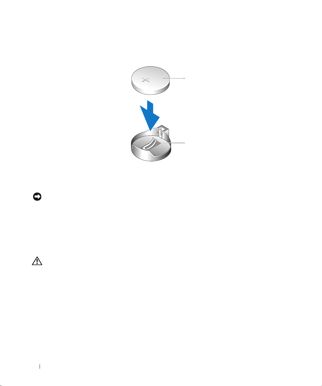
5
Insert the new battery into the socket with the side labeled "+" facing up, and snap the battery into
place.
1
2
1 battery 2 battery socket
6
Replace the computer cover (see "Replacing the Computer Cover" on page 90).
NOTICE: To connect a network cable, first plug the cable into the network port or device, and then plug it into the
computer.
7
Connect your computer and devices to electrical outlets, and then turn them on.
8
Enter system setup (see "System Setup" on page 97) and restore the settings you recorded in step 1.
9
Properly dispose of the old battery. See the
Product Information Guide
for battery disposal information.
Replacing the Computer Cover
CAUTION: Before you begin any of the procedures in this section, follow the safety instructions located in the
Product Information Guide.
1
Ensure that all cables are connected, and fold cables out of the way.
Gently pull the power cables toward you so that they do not get caught underneath the drives.
2
Ensure that no tools or extra parts are left inside the computer.
90 Removing and Installing Parts
Page 91
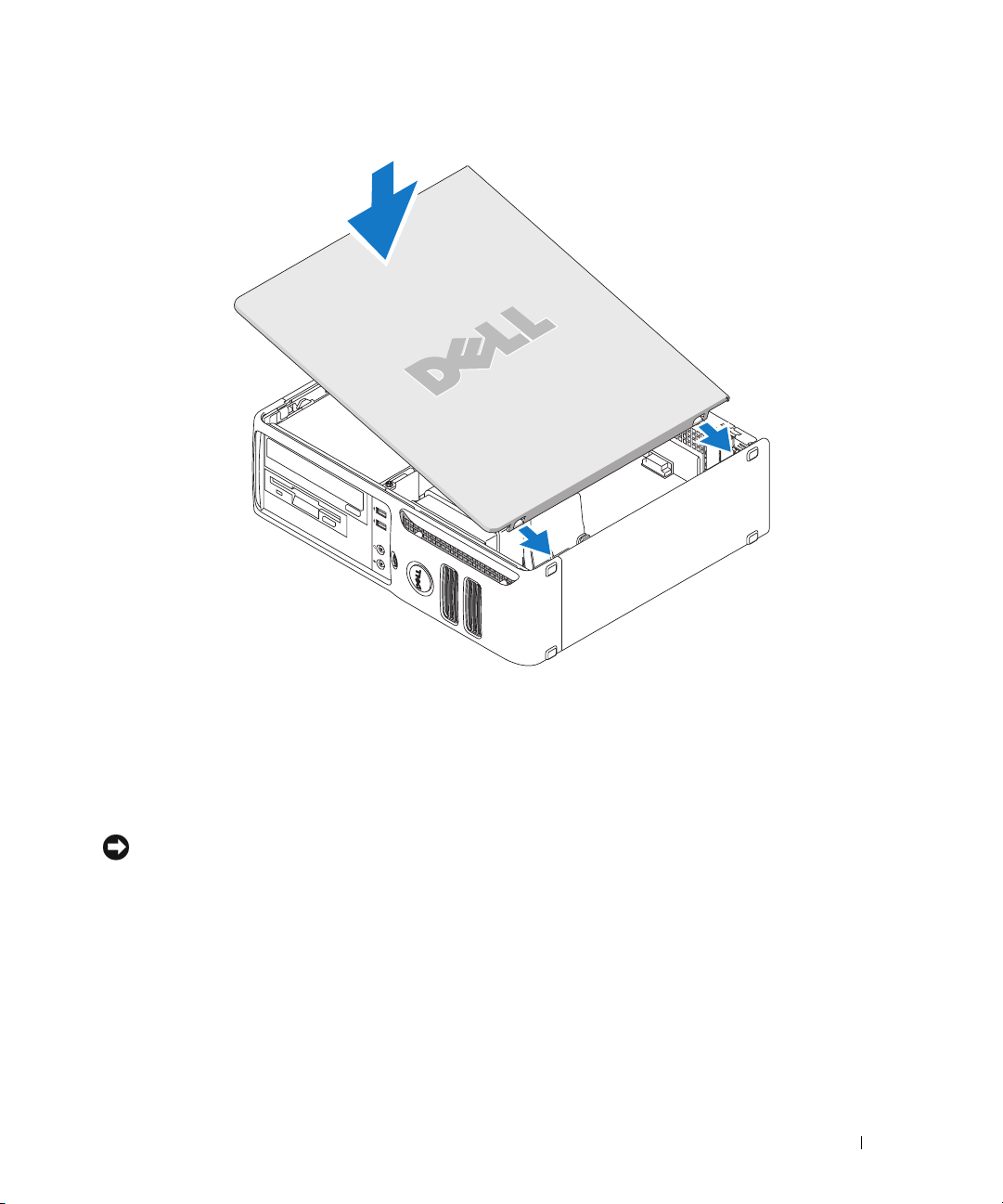
3
To replace the cover:
a
Align the bottom of the cover with the hinge tabs located along the bottom edge of the computer.
b
Using the hinge tabs as leverage, rotate the cover downward to close it.
c
Press the cover down until it snaps into place.
d
Ensure that the cover is seated correctly before moving the computer.
NOTICE: To connect a network cable, first plug the cable into the network port or device, and then plug it into the
computer.
4
Connect your computer and devices to electrical outlets, and then turn them on.
Removing and Installing Parts 91
Page 92

92 Removing and Installing Parts
Page 93

Appendix
Specifications
Microprocessor
™
Sempron
™
64 X2 Dual-Core processor
Microprocessor type AMD Athlon
AMD Athlon 64
AMD
Internal L2 cache up to 1 MB per core
up to 256 KB for Sempron
Memory
Type 533-MHz, 667-MHz, 800-MHz z (when available) DDR2 SDRAM
Memory connectors 4
Memory modules supported 256-MB, 512-MB, or 1-GB non-ECC
Minimum memory 256 MB
Maximum memory 4 GB
Computer Information
Chipset nVidia GeForce 6150LE
DMA channels eight
Interrupt levels 24
BIOS chip (NVRAM) 4 Mb
NIC integrated network interface
Capable of 10/100 communication
Video
Type nVidia integrated video (DirectX 9.0c Shader Model 3.0 Graphics
Processing Unit) or PCI Express x16 graphics card
Appendix 93
Page 94

Audio
Type Sigma Tel 9227 CODEC (7.1 Channel Audio)
Controllers
Drives two SATA controllers supporting two devices
Expansion Bus
Bus type PCI 2.3
PCI Express 1.0A
SATA 1.0A and 2.0
USB 2.0
Bus speed PCI: 133 MB/s
PCI Express x16: 40 Gbps bidirectional speed
PCI Express x1: 2.5 Gbps
SATA: 1.5 Gbps and 3.0 Gbps
USB: 480 Mbps high speed, 12Mbps full speed, 1.2 Mbps low
speed
Cards
PCI
connectors
card size
connector size
connector data width
(maximum)
PCI Express:
connectors
power
connector size
connector data width
(maximum)
one
low profile
124 pins
32 bits
one x1 and one x16
10 W (x1) and 25 W (x16) maximum
36 pins (x1) and 164 pins (x16)
one PCI Express lane (x1) and 16 PCI Express lanes (x16)
Drives
Externally accessible one 3.5-inch drive
one 5.25-inch drive bays
Available devices SATA hard drive, CD drive, DVD drive, DVD +/- RW drive, and
CD-RW/DVD Combo drive
Internally accessible one bay for a 1-inch-high hard drive
94 Appendix
Page 95

Connectors
External connectors:
Video
Network adapter
USB
Audio
System board connectors:
SATA
Floppy drive
Fan
PCI 2.3
PCIe-x1
PCIe-x16
Internal USB
Speaker
Memory modules
Power 12V
Power
Battery
15-hole VGA connector
RJ45 connector
two front-panel and four back-panel USB 2.0–compliant
connectors
six connectors for line-in and line-out; two front-panel connectors
for headphones and microphone
two 7-pin connectors
34-pin connector
5-pin connector
one 124-pin connectors
36-pin connector
164-pin connector
10-pin connector (supports two USB ports)
5-pin connector
four 240-pin connector
4-pin connector
24-pin connector
2-pin socket
Controls and Lights
Power control push button
Power light green light — Blinking green indicates a sleep mode; solid green
indicates a power-on state.
amber light — Blinking amber indicates a problem with an
installed device; solid amber indicates an internal power problem
(see "Power Problems" on page 40).
Hard-drive access light green
Link light solid green light indicates network connection
Link integrity light (on integrated
network adapter)
green light for 10-Mb operation; orange light for 100-Mb operation
Appendix 95
Page 96

Controls and Lights
Activity light (on integrated network
adapter)
Diagnostic lights Four lights on the front panel. See "Diagnostic Lights" on page 48.
Standby power light AUX_PWR on the system board
Power
DC power supply:
Wattage
Heat dissipation
yellow blinking light
280 W
955.39 BTU/hr maximum
NOTE: Heat dissipation is calculated based upon the power supply
rating.
Vo lt ag e
Backup battery 3-V CR2032 lithium coin cell
Physical
Height
Width
Depth
We ig ht
manual selection power supplies — 90 to 135 V at 50/60 Hz; 180 to
265 V at 50/60 Hz
11.4 cm (4.5 inches)
39.9 cm (15.7 inches)
35.3 cm (13.9 inches)
10.4 kg (23 lb)
Environmental
Temperature:
Operating
Storage
Relative humidity 20% to 80% (noncondensing)
Maximum vibration:
Operating
Storage
Maximum shock:
Operating
Storage
10° to 35°C (50° to 95°F)
–40° to 65°C (–40° to 149°F)
0.25 G at 3 to 200 Hz at 0.5 octave/min
0.5 G at 3 to 200 Hz at 1 octave/min
bottom half-sine pulse with a change in velocity of 50.8 cm/sec
(20 inches/sec)
27-G faired square wave with a velocity change of 508 cm/sec
(200 inches/sec)
96 Appendix
Page 97

Environmental (continued)
Altitude:
Operating
Storage
–15.2 to 3048 m (–50 to 10,000 ft)
–15.2 to 10,668 m (–50 to 35,000 ft)
System Setup
Overview
Use system setup as follows:
• To change the system configuration information after you add, change, or remove any hardware in your
computer
• To set or change a user-selectable option such as the user password
• To read the current amount of memory or set the type of hard drive installed
Before you use system setup, it is recommended that you write down the system setup screen information
for future reference.
NOTICE: Unless you are an expert computer user, do not change the settings for this program. Certain changes
can make your computer work incorrectly.
Entering System Setup
1
Turn on (or restart) your computer.
2
When the blue DELL™ logo is displayed, you must watch for the F2 prompt to appear.
3
Once this F2 prompt appears, press <F2> immediately.
NOTE: The F2 prompt indicates that the keyboard has initialized. This prompt can appear very quickly, so you
must watch for it to display, and then press <F2>. If you press <F2> before you are prompted, this keystroke
will be lost.
4
If you wait too long and the operating system logo appears, continue to wait until you see the
Microsoft
®
Windows® desktop, then, shut down your computer (see "Turning Off Your Computer" on
page 59) and try again.
System Setup Screen
The system setup screen displays current or changeable configuration information for your computer.
Information on the screen is divided into four areas: the menu at the top, the main window, the Item Help
field on the right, and key functions listed on the bottom.
Appendix 97
Page 98
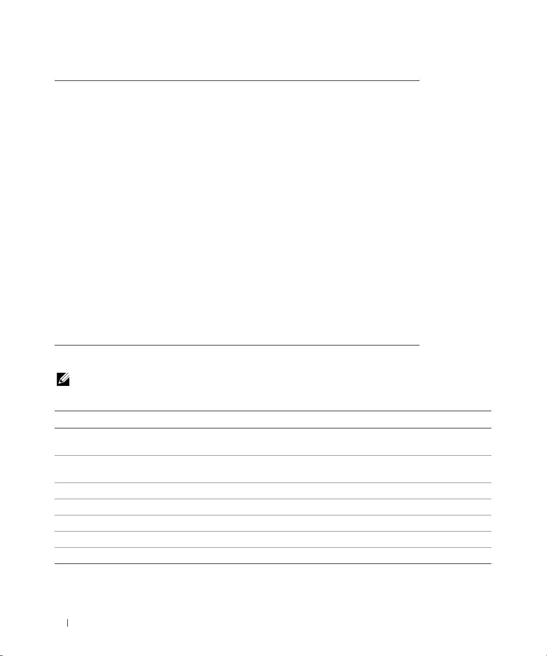
Options List — This
field appears on the left
side of the system setup
window. The field is a
scrollable list containing
features that define the
Option Field — This field contains information about each
option. In this field you can view your current settings and
make changes to your settings.
Use the right- and left-arrow keys to highlight an option.
Press <Enter> to make that selection active.
configuration of your
computer, including
installed hardware, power
conservation, and
security features.
Scroll up and down the
list by using the up and
down arrow keys. As an
option is highlighted, the
Option Field displays
more information about
that option and the
option’s current and
Key Functions — This field appears below the Option
Field and lists keys and their functions within the active
system setup field.
available settings.
System Setup Options
NOTE: Depending on your computer and installed devices, the items listed in this section may not appear, or may
not appear exactly as listed.
System
System Info Lists the computer name, BIOS Version, Service Tag, Express Service Code, (if
applicable), and the Asset Tag. None of these fields can be modified.
Processor Info Identifies the CPU type, processor clock speed, bus speed, L2 cache size, and processor
ID. States whether the processor supports 64-bit technology.
Memory Info Lists the type, size, speed, and channel mode (dual or single) of installed memory.
PCI Info Identifies any installed PCI or PCI Express cards.
Date/Time Displays current date and time settings.
Boot Sequence The computer attempts to boot from the sequence of devices specified in this list.
HDD Boot Sequence Lists the order that the BIOS will search the available hard drives in the system.
98 Appendix
Page 99

Drives
Diskette Drive
(
Internal
Drive 0: (SATA-0)
(On default)
Drive 1: (SATA-1)
(On default)
SMART Reporting
(Off default)
Onboard Devices
Integrated NIC
(On default)
Integrated Audio
(On default)
USB Controller
(On default)
Rear Dual USB0
(On default)
Rear Dual USB1
(On default)
Front USB
(On default)
default)
This option enables or disables the floppy drive. The options are Off, USB, Internal,
and Read Only.
NOTE: If USB is selected, ensure that USB Controller setup option under Onboard
Devices is set to On.
Identifies and enables and disables the drives attached to the SATA connectors on the
system board and lists the capacities for the hard drives.
Identifies and enables and disables the drives attached to the SATA connectors on the
system board and lists the capacities for the hard drives.
This setting determines whether integrated drive errors are reported or not during
system startup.
Enables or disables the integrated NIC controller.
w/RPL. When the On w/ PXE or the On w/RPL setting is active, if a boot routine is not
available from the network server, the computer attempts to boot from the next device in the
boot sequence list.
Enables or disables the onboard audio controller.
Enables or disables the internal USB controller. No Boot enables the controller but
disables the ability to boot from a USB device.
Settings are Off, On, On w/ PXE, or On
NOTE: Operating systems with USB support will recognize USB floppy drives regardless
of the No Boot setting.
Enables or disables the indicated group of USB ports on the back of the computer.
Enables or disables the indicated group of USB ports on the back of the computer.
Enables or disables the indicated group of USB ports on the front of the computer.
Appendix 99
Page 100

Video
Primary Video
(Auto default)
This setting specifies which video controller is primary when there is two video
controllers availble (PCI, Onboard, Auto, and PEG). This selection only matters when
if there are two video controllers present. When Auto is selected, the add-in video
controller will be used.
NOTE: A PCI Express graphics card will override the integrated video controller.
Video Memory Size
(64MB default)
Performance
HDD Acoustic Mode
(Bypass default)
This setting configures the amount of system memory that is reserved for the
integrated video controller. The settings are Auto, 16MB, 32MB, 64MB, 128MB, or
Off.
•
Bypass
— Your computer does not test or change the current acoustics mode setting.
•
Quiet
— The hard drive operates at its most quiet setting.
•
Suggested
•
Performance —
— The hard drive operates at the level suggested by the drive manufacturer.
The hard drive operates at its maximum speed.
NOTE: Switching to performance mode may cause the drive to be noisier, but its
performance is not affected. Changing the acoustics setting does not alter your hard-drive
image.
Security
Unlock Setup When an administrator password is being used, allows the user access to modify
system setup settings. Enter the administrator password at the prompt to unlock
system setup. If the correct password is not entered here, the user can view but not
modify system setup fields.
Admin Password
(Not Set default)
System Password
(Not Set default)
Password Changes
(Unlocked default)
Non-Execute Func
(On default)
Displays the current status of your system setup program’s password security feature
and allows you to verify and assign a new admin password.
Displays the current status of the system's password security feature and allows a new
system password to be assigned and verified.
Determines the interaction between the System password and the Admin password.
Locked prevents a user without a valid Admin password from being able to modify the
System password. Unlocked allows a user with a valid System password to modify the
system password.
Enables or disables Execute Disable memory protection technology.
100 Appendix
 Loading...