

Page 1

Dell™ Dimension™ 2010 Service Manual
Model D05M Type D05M001
www.dell.com | support.dell.com
Page 2

Notes, Cautions, and Warnings
NOTE: A NOTE indicates important information that helps you make better use of
your computer.
CAUTION: A CAUTION indicates potential damage to hardware or loss of data if
instructions are not followed.
WARNING: A WARNING indicates a potential for property damage, personal
injury, or death.
____________________
Information in this document is subject to change without notice.
© 2009 Dell Inc. All rights reserved.
Reproduction of these materials in any manner whatsoever without the written permission of Dell Inc.
is strictly forbidden.
Trademarks used in this text: Dell, the DELL logo, and Dimension are trademarks of Dell Inc.;
Microsoft and Windows are either trademarks or registered trademarks of Microsoft Corporation in
the United States and/or other countries.
Other trademarks and trade names may be used in this document to refer to either the entities claiming
the marks and names or their products. Dell Inc. disclaims any proprietary interest in trademarks and
trade names other than its own.
Model D05M Type D05M001
July 2009 Rev. A00
Page 3

Contents
1 Technical Overview . . . . . . . . . . . . . . . . . . 7
Inside View of Your Computer . . . . . . . . . . . . . . 7
System Board Components
. . . . . . . . . . . . . . . . 8
2 Before You Begin . . . . . . . . . . . . . . . . . . 11
Technical Specifications . . . . . . . . . . . . . . . . 11
Recommended Tools
Turning Off Your Computer
Safety Instructions . . . . . . . . . . . . . . . . . . . 12
. . . . . . . . . . . . . . . . . . 11
. . . . . . . . . . . . . . . 11
3 Computer Cover . . . . . . . . . . . . . . . . . . . 15
Removing the Computer Cover . . . . . . . . . . . . . 15
Replacing the Computer Cover
. . . . . . . . . . . . . 16
4 Front Bezel . . . . . . . . . . . . . . . . . . . . . . . 19
Removing the Front Bezel . . . . . . . . . . . . . . . . 19
Replacing the Front Bezel
. . . . . . . . . . . . . . . . 20
Contents 3
Page 4

5 Memory Module(s) . . . . . . . . . . . . . . . . . 21
Removing Memory Module(s) . . . . . . . . . . . . . . 21
Replacing Memory Module(s)
. . . . . . . . . . . . . . 22
6 PCI and PCI Express Cards . . . . . . . . . . . 25
Removing PCI and PCI Express Cards . . . . . . . . . . 25
Replacing PCI and PCI Express Cards
. . . . . . . . . 27
Configuring Your Computer After Removing or
Installing a PCI/PCI Express Card
. . . . . . . . . . . . 30
7Drives . . . . . . . . . . . . . . . . . . . . . . . . . . . 31
Removing a Hard Drive . . . . . . . . . . . . . . . . . 31
Replacing a Hard Drive . . . . . . . . . . . . . . . . . 33
Removing a Media Card Reader
Replacing a Media Card Reader
Removing an Optical Drive
Replacing an Optical Drive
. . . . . . . . . . . . 33
. . . . . . . . . . . . 35
. . . . . . . . . . . . . . . 37
. . . . . . . . . . . . . . . 39
8 Power Switch Module . . . . . . . . . . . . . . . 43
4 Contents
Removing the Power Switch Module . . . . . . . . . . 43
Replacing the Power Switch Module
. . . . . . . . . . 45
Page 5

9 Front I/O Panel . . . . . . . . . . . . . . . . . . . . 47
Removing the Front I/O Panel . . . . . . . . . . . . . . 47
Replacing the Front I/O Panel
. . . . . . . . . . . . . . 48
10 Processor Fan and
Heat Sink Assembly 51
Removing the Processor Fan and
Heat Sink Assembly . . . . . . . . . . . . . . . . . . . 51
Replacing the Processor Fan and
Heat Sink Assembly
. . . . . . . . . . . . . . . . . . . 53
11 Processor . . . . . . . . . . . . . . . . . . . . . . . . 55
Removing the Processor . . . . . . . . . . . . . . . . 55
Replacing the Processor . . . . . . . . . . . . . . . . 57
12 System Board . . . . . . . . . . . . . . . . . . . . . 59
Removing the System Board . . . . . . . . . . . . . . 59
Replacing the System Board
. . . . . . . . . . . . . . 61
13 Power Supply . . . . . . . . . . . . . . . . . . . . . 63
Removing the Power Supply . . . . . . . . . . . . . . 63
Replacing the Power Supply
. . . . . . . . . . . . . . 64
Contents 5
Page 6

14 Battery . . . . . . . . . . . . . . . . . . . . . . . . . . . 67
Removing the Battery . . . . . . . . . . . . . . . . . . 67
Replacing the Battery
. . . . . . . . . . . . . . . . . . 68
15 System Setup . . . . . . . . . . . . . . . . . . . . . . 69
Overview . . . . . . . . . . . . . . . . . . . . . . . . . 69
Entering System Setup
System Setup Screens
System Setup Options
Changing Boot Sequence for the
Current Boot . . . . . . . . . . . . . . . . . . . . 74
Changing Boot Sequence for Future Boots
Clearing Forgotten Passwords and CMOS Settings
Flashing the BIOS
. . . . . . . . . . . . . . . . . . 69
. . . . . . . . . . . . . . . 69
. . . . . . . . . . . . . . . 71
. . . . 74
. . 75
. . . . . . . . . . . . . . . . . . . . 76
6 Contents
Page 7
Technical Overview
1
2
3
4
5
6
WARNING: Before working inside your computer, read the safety information
that shipped with your computer. For additional safety best practices information,
see the Regulatory Compliance Homepage at
www.dell.com/regulatory_compliance.
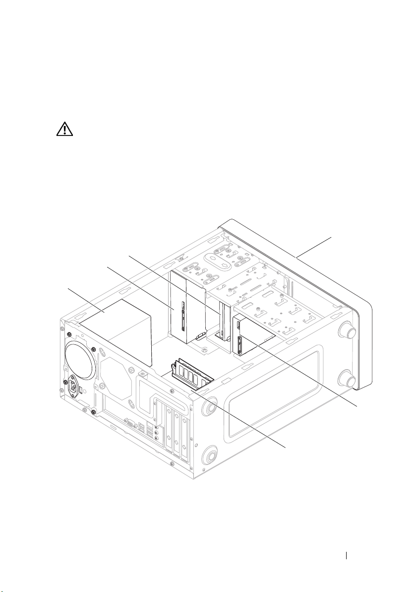
Inside View of Your Computer
1
Technical Overview 7
Page 8
1 power supply 2 optical drive
1 2 345
6
7
8
9
10
11
12
13
14
15
16
17
3 Media Card Reader 4 front bezel
5 hard drive 6 system board
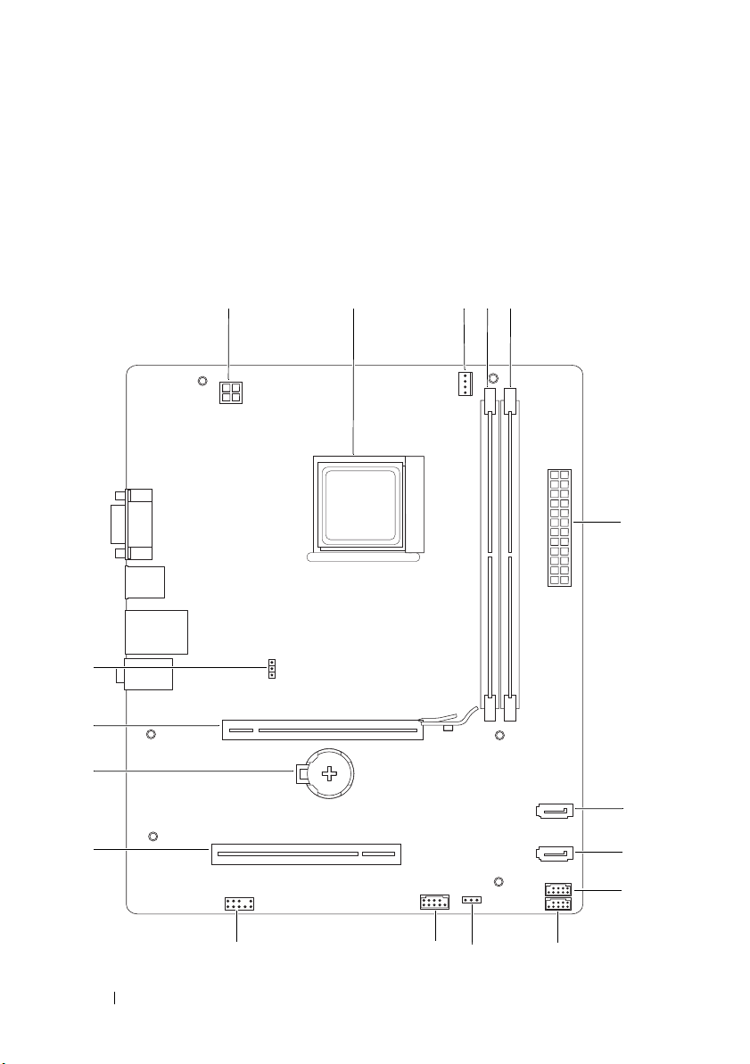
System Board Components
8 Technical Overview
Page 9

1 12 V power connector (PWR2) 2 processor socket
3 processor fan connector
(CPU_FAN)
5 memory module connector
(DIMM2)
7 SATA connector (SATA_3) 8 SATA connector (SATA_1)
9 media card reader connector
(F_USB2)
11 USB power connector
(USB_PWR1)
13 front panel audio (F_AUDIO) 14 PCI card slot (PCI2)
15 battery socket (BAT) 16 PCI-Express x16 card slot
17 CMOS reset jumper
(CLR_CMOS)
4 memory module connector
(DIMM1)
6 main power connector (PWR1)
10 front panel USB connector
(F_USB1)
12 power switch module connector
(FP1)
(PCI-E1_16X)
Technical Overview 9
Page 10

10 Technical Overview
Page 11

2
Before You Begin
This manual provides procedures for removing and installing the components
in your computer. Unless otherwise noted, each procedure assumes that the
following conditions exist:
• You have performed the steps in "Turning Off Your Computer" on page 11
and "Safety Instructions" on page 12.
• You have read the safety information that ships with your computer
• A component can be replaced or—if purchased separately—installed by
performing the removal procedure in reverse order.
Technical Specifications
For information on technical specifications of your computer, see the Setup
Guide that shipped with your computer or see the Dell Support website at
support.dell.com/manuals.
Recommended Tools
The procedures in this document may require the following tools:
• Small Phillips screwdriver
• Small flat-blade screwdriver
.
Turning Off Your Computer
CAUTION: To avoid losing data, save and close all open files and exit all open
programs before you turn off your computer.
1
Shut down the operating system.
Before You Begin 11
Page 12
2
Ensure that the computer and all attached devices are turned off. If your
computer and attached devices did not automatically turn off when you
shut down your operating system, press and hold the power button for
about 4 seconds to turn them off.
Safety Instructions
Use the following safety guidelines to help protect your computer from
potential damage and to help to ensure your own personal safety.
WARNING: Before working inside your computer, read the safety information
that shipped with your computer. For additional safety best practices information,
see the Regulatory Compliance Homepage at
www.dell.com/regulatory_compliance.
CAUTION: Only a certified service technician should perform repairs on your
computer. Damage due to servicing that is not authorized by Dell is not covered by
your warranty.
CAUTION: When you disconnect a cable, pull on its connector or on its pull-tab,
not on the cable itself. Some cables have connectors with locking tabs; if you are
disconnecting this type of cable, press in on the locking tabs before you
disconnect the cable. As you pull connectors apart, keep them evenly aligned to
avoid bending any connector pins. Also, before you connect a cable, ensure that
both connectors are correctly oriented and aligned.
CAUTION: To avoid damaging the computer, perform the following steps before
you begin working inside the computer.
1
Ensure that the work surface is flat and clean to prevent the computer
cover from being scratched.
2
Turn off your computer (see "Turning Off Your Computer" on page 11).
CAUTION: To disconnect a network cable, first unplug the cable from your
computer and then unplug the cable from the network device.
3
Disconnect all telephone or network cables from the computer.
4
Disconnect your computer and all attached devices from their electrical
outlets.
5
Press and hold the power button while the system is unplugged to ground
the system board.
12 Before You Begin
Page 13

CAUTION: Before touching anything inside your computer, ground yourself by
touching an unpainted metal surface, such as the metal at the back of the
computer. While you work, periodically touch an unpainted metal surface to
dissipate static electricity, which could harm internal components.
Before You Begin 13
Page 14

14 Before You Begin
Page 15
Computer Cover
WARNING: Before working inside your computer, read the safety information
that shipped with your computer. For additional safety best practices information,
see the Regulatory Compliance Homepage at
www.dell.com/regulatory_compliance.
WARNING: To guard against electrical shock, always unplug your computer from
the electrical outlet before removing the cover.
WARNING: Do not operate your equipment with any cover(s) (including computer
covers, bezels, filler brackets, front-panel inserts, etc.) removed.
CAUTION: Ensure that sufficient space exists to support the system with the
cover removed—at least 30 cm (1 ft.) of desk top space.
Removing the Computer Cover
1
Follow the procedures in "Before You Begin" on page 11.
2
Lay your computer on its side with the computer cover facing up.
3
Remove the two screws securing the cover, using a screwdriver.
3
Computer Cover 15
Page 16
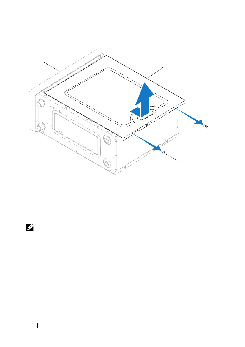
1 front of computer 2 computer cover 3 screws (2)
3
2
1
4
Release the computer cover by pulling it away from the front of the
computer and lifting it up.
5
Set the cover aside in a secure location.
NOTE: To remove the computer cover on the other side, lay the computer on its
side with the unremoved cover facing up, and then perform step 3 to step 5.
Replacing the Computer Cover
1
Ensure that all cables are connected, and fold cables out of the way.
2
Ensure that no tools or extra parts are left inside the computer.
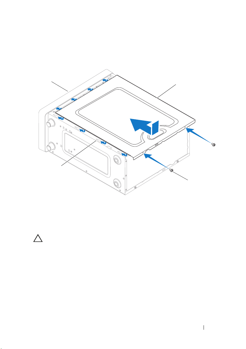
3
Align the tabs at the bottom of the computer cover with the slots located
along the edge of the computer.
4
Press the computer cover down and slide it towards the front of the computer
until you feel a click or feel the computer cover securely installed.
16 Computer Cover
Page 17
5
3
4
1
2
Ensure that the cover is seated correctly.
6
Replace the two screws that secure the computer cover, using a screwdriver.
1 front of the computer 2 computer cover
3 screws (2) 4 slot
7
Place the computer in an upright position.
CAUTION: Ensure that none of the system air-vents are blocked. Blocking them
would cause serious thermal problems.
Computer Cover 17
Page 18

18 Computer Cover
Page 19
Front Bezel
WARNING: Before working inside your computer, read the safety information
that shipped with your computer. For additional safety best practices information,
see the Regulatory Compliance Homepage at
www.dell.com/regulatory_compliance.
WARNING: To guard against electrical shock, always unplug your computer from
the electrical outlet before removing the cover.
WARNING: Do not operate your equipment with any cover(s) (including computer
covers, bezels, filler brackets, front-panel inserts, etc.) removed.
Removing the Front Bezel
1
Follow the procedures in "Before You Begin" on page 11.
2
Remove the computer cover from both the sides (see "Removing the
Computer Cover" on page 15).
3
Place the computer in an upright position.
4
Press out the six front bezel clamps to release it from the front panel.
4
Front Bezel 19
Page 20
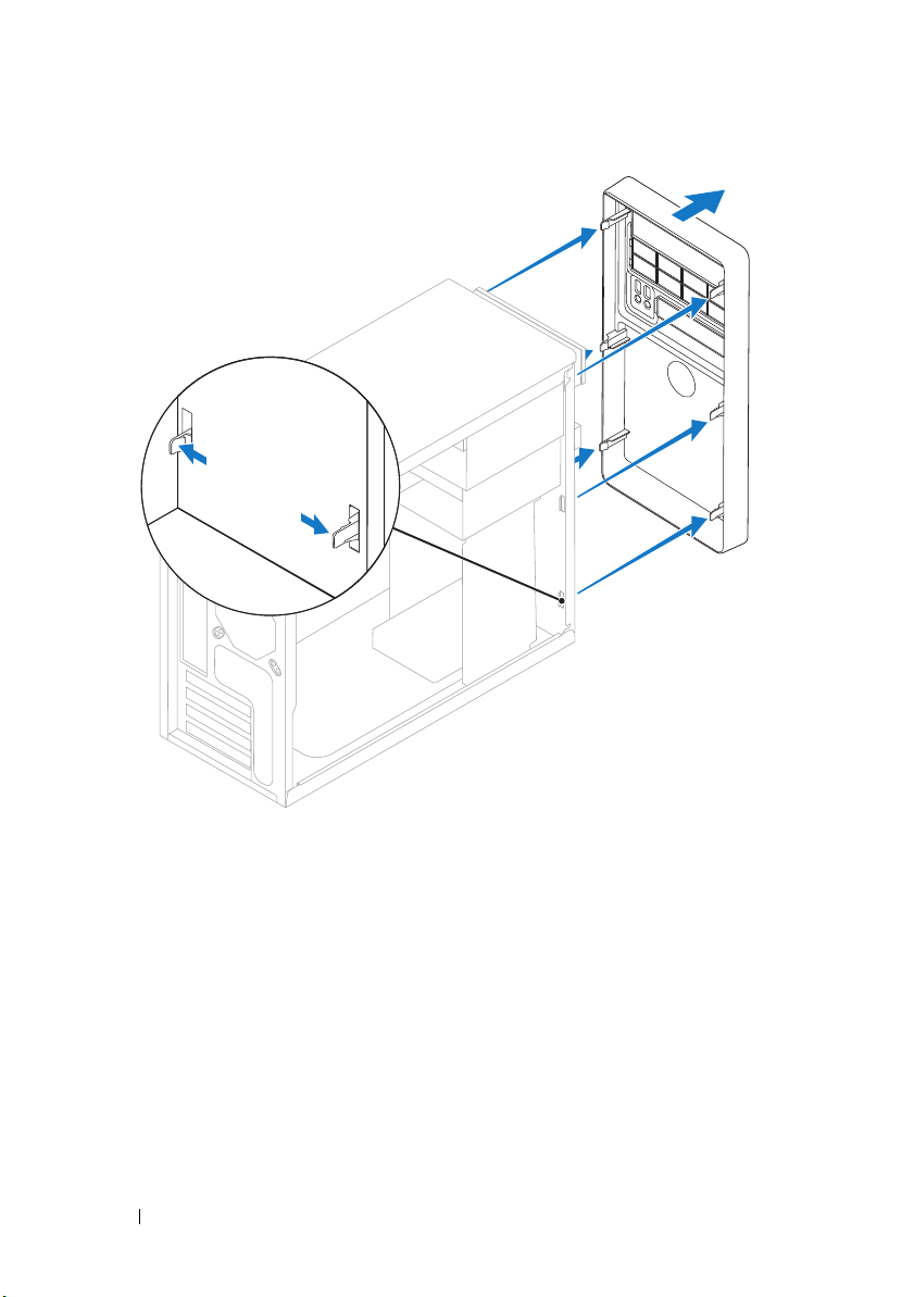
5
Pull the front bezel away from the front of the computer to release it from
the front bezel inserts.
6
Set aside the front bezel in a secure location.
Replacing the Front Bezel
1
Align the clamps of the front bezel to the front panel and press it towards
the computer until the front bezel clamps snap into place.
2
Replace the computer cover on both the sides (see "Replacing the
Computer Cover" on page 16).
20 Front Bezel
Page 21
Memory Module(s)
2
1
WARNING: Before working inside your computer, read the safety information
that shipped with your computer. For additional safety best practices information,
see the Regulatory Compliance Homepage at
www.dell.com/regulatory_compliance.
WARNING: To guard against electrical shock, always unplug your computer from
the electrical outlet before removing the cover.
WARNING: Do not operate your equipment with any cover(s) (including computer
covers, bezels, filler brackets, front-panel inserts, etc.) removed.
Removing Memory Module(s)
1
Follow the procedures in "Before You Begin" on page 11.
2
Remove the computer cover (see "Removing the Computer Cover" on
page 15).
3
Locate the memory modules on the system board (see "System Board
Components" on page 8).
4
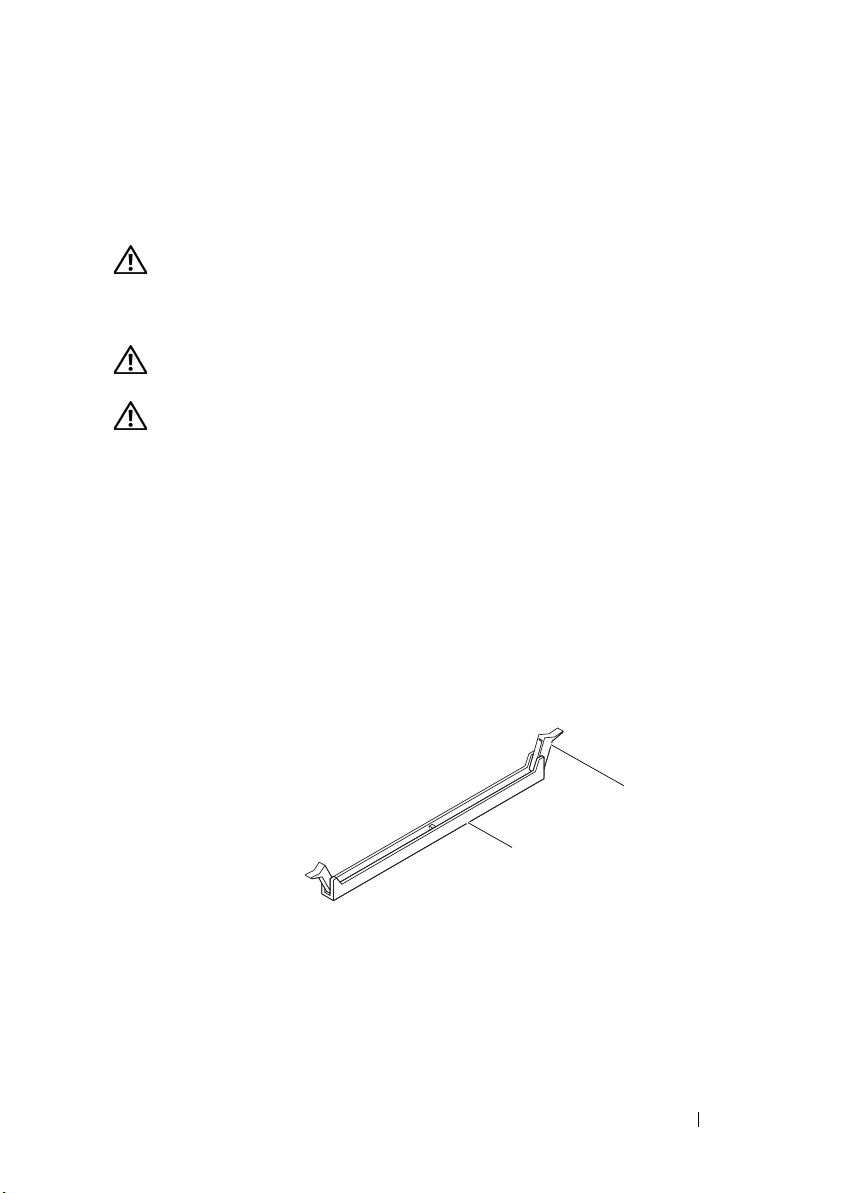
Press out the securing clip at each end of the memory module connector.
5
1 memory module connector 2 securing clips (2)
5
Grasp the memory module and pull it upwards.
If the memory module is difficult to remove, gently ease the memory
module back and forth to remove it from the connector.
Memory Module(s) 21
Page 22
Replacing Memory Module(s)
3
2
1
4
1
Follow the procedures in "Before You Begin" on page 11.
2
Press out the securing clip at each end of the memory module connector.
CAUTION: Do not install ECC memory modules.
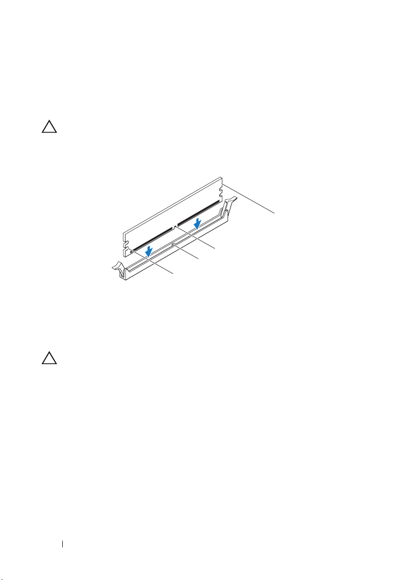
3
Align the notch on the bottom of the memory module with the tab in the
memory module connector.
1 cutouts (2) 2 tab
3 notch 4 memory module
CAUTION: To avoid damage to the memory module, press the memory module
straight down into the connector while you apply equal force to each end of the
memory module.
4
Insert the memory module into the memory module connector until the
memory module snaps into position.
If you insert the memory module correctly, the securing clips snap into the
cutouts at each end of the memory module.
22 Memory Module(s)
Page 23
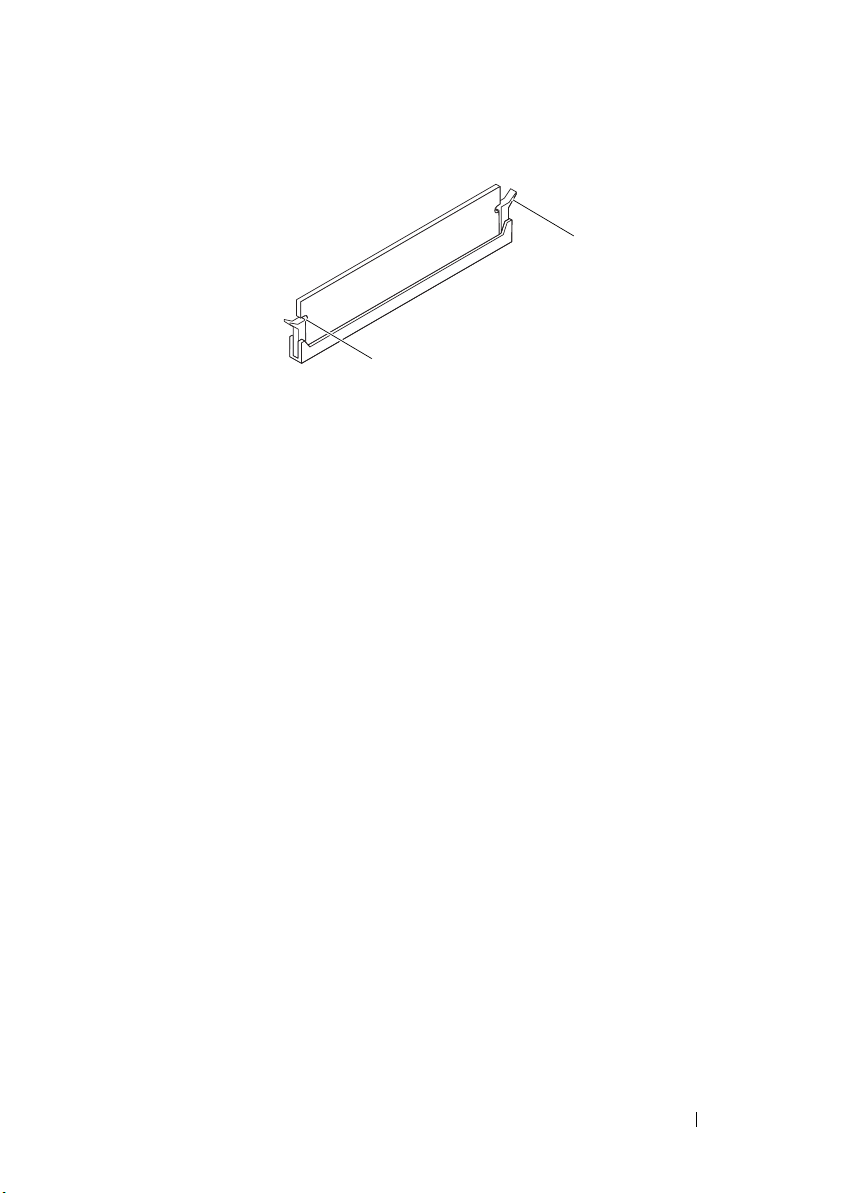
1 cutouts (2) 2 securing clip (snapped in position)
2
1
5
Replace the computer cover (see "Replacing the Computer Cover" on
page 16).
6
Connect your computer and devices to electrical outlets, and then turn
them on.
If the message appears stating that memory size has changed, press <F1>
to continue.
7
Log on to your computer.
8
Right-click the
desktop and click
9
Click the
10
To verify that the memory is installed correctly, check the amount of
My Computer
General
Properties
tab.
icon on your Microsoft® Windows®
.
memory (RAM) listed.
Memory Module(s) 23
Page 24

24 Memory Module(s)
Page 25

PCI and PCI Express Cards
WARNING: Before working inside your computer, read the safety information
that shipped with your computer. For additional safety best practices information,
see the Regulatory Compliance Homepage at
www.dell.com/regulatory_compliance.
WARNING: To guard against electrical shock, always unplug your computer from
the electrical outlet before removing the cover.
WARNING: Do not operate your equipment with any cover(s) (including computer
covers, bezels, filler brackets, front-panel inserts, etc.) removed.
Removing PCI and PCI Express Cards
1
Follow the procedures in "Before You Begin" on page 11.
2
Remove the computer cover (see "Removing the Computer Cover" on
page 15).
3
If necessary, disconnect any cables connected to the card.
4
Remove the screw the secures the card to the chassis.
6
PCI and PCI Express Cards 25
Page 26

1 screw 2 card
2
1
5
Remove the card.
• For a PCI card, grasp the card by its top corners, and ease it out of its
connector.
• For a PCI Express x16 card, push the retention mechanism on the card
connector as you grasp the card by its top corners, and then ease the
card out of the connector.
26 PCI and PCI Express Cards
Page 27

1 PCI Express x16 card 2 PCI Express x16 card connector
2
1
4
3
3 securing tab 4 retention mechanism
6
If you are removing the card permanently, install a filler bracket in the
empty card-slot opening.
NOTE: Installing filler brackets over empty card-slot openings is necessary to
maintain FCC certification of the computer. The brackets also keep dust and
dirt out of your computer.
7
Replace the computer cover (see "Replacing the Computer Cover" on
page 16).
8
Connect the computer and devices to electrical outlets, and then turn
them on.
9
Remove the card’s driver from the operating system.
10
To complete the removal procedure, see "Configuring Your Computer
After Removing or Installing a PCI/PCI Express Card" on page 30.
Replacing PCI and PCI Express Cards
1
Follow the procedures in "Before You Begin" on page 11.
2
Remove the computer cover (see "Removing the Computer Cover" on
page 15).
3
Prepare the card for installation.
PCI and PCI Express Cards 27
Page 28

See the documentation that came with the card for information on
1
4
3
5
2
configuring the card, making internal connections, or otherwise
customizing it for your computer.
4
If this is a new card installation, remove the
5
Place the card in the connector and press down firmly. Ensure that the card
break-away metal plate
is fully seated in the slot.
.
1 not fully-seated
card
4 bracket within slot 5 break-away metal plate
If you are installing the PCI Express card into the x16 card connector, pull
the retention mechanism and align the securing tab with the card
connector.
2 fully-seated card 3 bracket caught
outside of slot
28 PCI and PCI Express Cards
Page 29

1 PCI Express x16 card 2 PCI Express x16 card connector
2
1
3
4
3 securing tab 4 retention mechanism
6
Place the card in the connector and press down firmly. Ensure that the card
is fully seated in the slot.
7
Replace the screw that secures the card to the chassis
8
Connect any cables that should be attached to the card.
See the documentation for the card for information about the card’s cable
connections.
CAUTION: Do not route card cables over or behind the cards. Cables routed over
the cards can prevent the computer cover from closing properly or cause damage
to the equipment.
9
Replace the computer cover (see "Replacing the Computer Cover" on
page 16).
10
To complete the installation, see "Configuring Your Computer After
Removing or Installing a PCI/PCI Express Card" on page 30.
PCI and PCI Express Cards 29
Page 30

Configuring Your Computer After Removing or Installing a PCI/PCI Express Card
NOTE: For information on location of external connectors, see the Setup Guide. For
information on installing drivers and software for your card, see the documentation
that shipped with the card.
Installed Removed
1
Sound Card
Network Card 1
Enter system setup (see
"Entering System Setup" on
page 69).
2
Go to
Onboard Audio
Controller
the setting to
3
Connect the external audio
devices to the sound card’s
connectors.
Enter system setup (see
"Entering System Setup" on
page 69).
2
Go to
Controller
the setting to
3
Connect the network cable
to the network card’s
connector.
and then change
Disabled
Onboard LAN
and then change
Disabled
.
.
1
Enter system setup (see
"Entering System Setup" on
page 69).
2
Go to
Onboard Audio
Controller
the setting to
3
Connect the external audio
devices to the computer’s back
panel connectors.
1
Enter system setup (see
"Entering System Setup" on
page 69).
2
Go to
Controller
the setting to
3
Connect the network cable to
the integrated network
connector.
and then change
Enabled
Onboard LAN
and then change
Enabled
.
.
30 PCI and PCI Express Cards
Page 31

Drives
WARNING: Before working inside your computer, read the safety information
that shipped with your computer. For additional safety best practices information,
see the Regulatory Compliance Homepage at
www.dell.com/regulatory_compliance.
WARNING: To guard against electrical shock, always unplug your computer from
the electrical outlet before removing the cover.
WARNING: Do not operate your equipment with any cover(s) (including computer
covers, bezels, filler brackets, front-panel inserts, etc.) removed.
Removing a Hard Drive
CAUTION: If you are replacing a hard drive that contains data that you want to
keep, back up your files before you begin this procedure.
1
Follow the procedures in "Before You Begin" on page 11.
2
Remove the computer cover from both the sides (see "Removing the
Computer Cover" on page 15).
3
Disconnect the power cable and the data cable from the hard drive.
NOTE: If you are not replacing the hard drive at this time, disconnect the
other end of the data cable from the system board and set it aside. You can
use the data cable to install a hard drive at a later time. For the location of the
SATA connectors, see "System Board Components" on page 8.
7
Drives 31
Page 32

1 power cable 2 data cable 3 screws (4)
3
2
1
CAUTION: Ensure that you do not scratch the screw holes with the screwdriver
as the hard disk circuit board assembly is exposed here.
4
Place the computer in an upright position.
5
Remove the four screws that secure the hard drive to the hard drive bay.
6
Slide the hard drive out towards the back of the computer.
7
If removing the hard drive changes the drive configuration, ensure that you
reflect these changes in system setup (see "System Setup" on page 69).
32 Drives
Page 33

8
Replace the computer cover on both the sides (see "Replacing the Computer
Cover" on page 16).
9
Connect the computer and other devices to an electrical outlet.
Replacing a Hard Drive
1
Follow the procedures in "Before You Begin" on page 11.
2
Remove the computer cover from both the sides (see "Removing the
Computer Cover" on page 15).
3
Check the documentation for the hard drive to verify that it is configured
for your computer.
4
Move the cables out of the way and slide the hard drive into the hard drive
bay.
5
Align and replace the four screws that secure the hard drive to the hard
drive bay.
6
Connect the power and data cables to the hard drive.
7
Ensure that you connect the data cable to the system board connector, if
you disconnected it while removing the hard drive. For the location of the
SATA connectors, see "System Board Components" on page 8.
8
Check all cables to be certain that they are properly connected and firmly
seated.
9
Replace the computer cover on both the sides (see "Replacing the
Computer Cover" on page 16).
10
Connect your computer and devices to electrical outlets, and then turn
them on.
11
See the documentation that came with the hard drive for instructions on
installing any software required for drive operation.
12
Check the System Setup for drive configuration changes (see "Entering
System Setup" on page 69).
Removing a Media Card Reader
1
Follow the procedures in "Before You Begin" on page 11.
Drives 33
Page 34

2
2
1
Remove the computer cover from both the sides (see "Removing the Computer
Cover" on page 15).
3
Remove the front bezel (see "Removing the Front Bezel" on page 19).
1 FlexBay USB cable 2 screws (2)
4
Disconnect the FlexBay USB cable from the Media Card Reader connector
on the system board. For the location of the connector, see "System Board
Components" on page 8.
5
Remove the two screws that secure the Media Card Reader to the FlexBay
slot.
34 Drives
Page 35

6
Slide the Media Card Reader out through the front of the computer.
7
Replace the front bezel (see "Replacing the Front Bezel" on page 20).
8
Replace the computer cover on both the sides (see "Replacing the
Computer Cover" on page 16).
9
Connect your computer and devices to electrical outlets, and then turn
them on.
Replacing a Media Card Reader
1
Follow the procedures in "Before You Begin" on page 11.
2
Remove the computer cover from both the sides (see "Removing the
Computer Cover" on page 15).
3
Remove the front bezel (see "Removing the Front Bezel" on page 19).
4
If this is a new Media Card Reader installation, remove the
metal plate
.
break-away
Drives 35
Page 36

1
36 Drives
1 break-away metal plate
5
Gently slide the Media Card Reader into place in the FlexBay slot.
Page 37

6
Align the screw holes in the Media Card Reader with the screw holes in the
FlexBay slot.
7
Replace the two screws that secure the Media Card Reader to the FlexBay
slot.
NOTE: Ensure that the Media Card Reader is installed before the FlexBay
USB cable is connected.
8
Connect the FlexBay USB cable to the Media Card Reader connector on
the system board. For the location of the connector, see "System Board
Components" on page 8.
9
Replace the front bezel (see "Replacing the Front Bezel" on page 20).
10
Replace the computer cover on both the sides (see "Replacing the
Computer Cover" on page 16).
11
Connect your computer and devices to electrical outlets, and then turn
them on.
Removing an Optical Drive
1
Follow the procedures in "Before You Begin" on page 11.
2
Remove the computer cover from both the sides (see "Removing the
Computer Cover" on page 15).
3
Remove the front bezel (see "Removing the Front Bezel" on page 19).
4
Disconnect the power cable and the data cable from the back of the
optical drive.
NOTE: If you are not replacing the optical drive at this time, disconnect the
other end of the data cable from the system board and set it aside. You can
use the data cable to install an optical drive at a later time. For the location of
the SATA connectors, see "System Board Components" on page 8.
Drives 37
Page 38

3
1
2
1 power cable 2 data cable 3 screws (4)
5
Remove the four screws that secure the optical drive to the optical drive
bay.
6
Slide the optical drive out through the front of the computer.
7
Replace the front bezel (see "Replacing the Front Bezel" on page 20).
8
Replace the computer cover on both the sides (see "Replacing the
Computer Cover" on page 16).
9
Connect your computer and devices to electrical outlets, and then turn
them on.
38 Drives
Page 39

10
1
Configure the drives in system setup (see "System Setup Options" on
page 71).
Replacing an Optical Drive
1
Follow the procedures in "Before You Begin" on page 11.
2
Remove the computer cover from both the sides (see "Removing the
Computer Cover" on page 15).
3
Remove the front bezel (see "Removing the Front Bezel" on page 19).
4
If you are installing an optical drive in the secondary optical drive slot,
remove the
break-away metal plate
.
1 break-away metal plate
Drives 39
Page 40

5
Gently slide the optical drive into place.
6
Align the screw holes in the optical drive with the screw holes in the optical
drive bay.
7
Replace the four screws that secure the optical drive to the optical drive
bay.
8
Connect the power and data cables to the optical drive.
9
Ensure that you connect the data cable to the system board connector, if
you disconnected it while removing the optical drive. For the location of
the SATA connectors, see "System Board Components" on page 8.
10
Replace the front bezel (see "Replacing the Front Bezel" on page 20).
11
Replace the computer cover on both the sides (see "Replacing the
Computer Cover" on page 16).
12
Connect your computer and devices to their electrical outlets, and turn
them on.
See the documentation that came with the optical drive for instructions
on installing any software required for drive operation.
13
Check the System Setup for drive configuration changes (see "Entering
System Setup" on page 69).
40 Drives
Page 41

Drives 41
Page 42

42 Drives
Page 43

Power Switch Module
WARNING: Before working inside your computer, read the safety information
that shipped with your computer. For additional safety best practices information,
see the Regulatory Compliance Homepage at
www.dell.com/regulatory_compliance.
WARNING: To guard against electrical shock, always unplug your computer from
the electrical outlet before removing the cover.
WARNING: Do not operate your equipment with any cover(s) (including computer
covers, bezels, filler brackets, front-panel inserts, etc.) removed.
CAUTION: Ensure that sufficient space exists to support the system with the
cover removed—at least 30 cm (1 ft.) of desk top space.
Removing the Power Switch Module
1
Follow the procedures in "Before You Begin" on page 11.
2
Remove the computer cover from both the sides (see "Removing the
Computer Cover" on page 15).
3
Remove the front bezel (see "Removing the Front Bezel" on page 19).
4
Remove the hard drive (see "Removing a Hard Drive" on page 31).
5
Disconnect the power switch module cable from power switch module
connector (FP1) on the system board. For the location of the connector,
see "System Board Components" on page 8.
6
Gently release the hard drive activity light from its holder.
7
Press the holder and rotate it outwards to remove it from the front panel.
8
Power Switch Module 43
Page 44

1
2
1 hard drive activity light 2 holder
44 Power Switch Module
Page 45

8
Slide the holder along with the hard drive activity light and cable out
through the front of the computer.
Replacing the Power Switch Module
1
Slide the power switch module through the slot on the front panel.
2
Press the holder and gently snap it into the front panel until it clicks into
place.
3
Gently push the hard drive activity light into its holder.
4
Connect the power switch module cable to the power switch module
connector (FP1) on the system board.
5
Replace the hard drive (see "Replacing a Hard Drive" on page 33).
6
Replace the front bezel (see "Replacing the Front Bezel" on page 20).
7
Replace the computer cover on both the sides (see "Replacing the
Computer Cover" on page 16).
Power Switch Module 45
Page 46

46 Power Switch Module
Page 47

Front I/O Panel
WARNING: Before working inside your computer, read the safety information
that shipped with your computer. For additional safety best practices information,
see the Regulatory Compliance Homepage at
www.dell.com/regulatory_compliance.
WARNING: To guard against electrical shock, always unplug your computer from
the electrical outlet before removing the cover.
WARNING: Do not operate your equipment with any cover(s) (including computer
covers, bezels, filler brackets, front-panel inserts, etc.) removed.
Removing the Front I/O Panel
NOTE: Note the routing of all cables as you remove them so that you can re-route
them correctly when installing the new front I/O panel.
1
Follow the procedures in "Before You Begin" on page 11.
2
Remove the computer cover from both the sides (see "Removing the
Computer Cover" on page 15).
3
Remove the front bezel (see "Removing the Front Bezel" on page 19).
CAUTION: When removing the front I/O panel from the computer, be extremely
careful. Carelessness may result in damage to the cable connectors and the cable
routing clips.
4
Disconnect all the cables that are connected to the front I/O panel from
the system board connectors.
5
Remove the screw that secures the front I/O panel to the chassis.
6
Carefully remove the front I/O panel from the computer.
9
Front I/O Panel 47
Page 48

1 front I/O panel 2 screw
1
2
Replacing the Front I/O Panel
1
Align the front I/O panel with the screw hole in the chassis.
48 Front I/O Panel
Page 49

2
Replace the screw that secures the front I/O panel to the chassis.
3
Connect the cables to the system board connectors.
4
Replace the front bezel (see "Replacing the Front Bezel" on page 20).
5
Replace the computer cover on both the sides (see "Replacing the Computer
Cover" on page 16).
6
Connect your computer and devices to an electrical outlet, and turn them on.
Front I/O Panel 49
Page 50

50 Front I/O Panel
Page 51

10
Processor Fan and Heat Sink Assembly
WARNING: Before working inside your computer, read the safety information
that shipped with your computer. For additional safety best practices information,
see the Regulatory Compliance Homepage at
www.dell.com/regulatory_compliance.
WARNING: To guard against likelihood of electric shock, laceration by moving
fan blades or other unexpected injuries, always unplug your computer from the
electrical outlet before removing the cover.
WARNING: Do not operate your equipment with any cover(s) (including computer
covers, bezels, filler brackets, front-panel inserts, etc.) removed.
Removing the Processor Fan and Heat Sink Assembly
CAUTION: The processor fan with the heat sink is one single unit. Do not try to
remove the fan separately.
CAUTION: Do not touch the fan blades when you are removing the processor fan
and heat sink assembly. This could damage the fan.
1
Follow the procedures in "Before You Begin" on page 11.
2
Remove the computer cover (see "Removing the Computer Cover" on
page 15).
3
Disconnect the processor fan and heat sink assembly cable from the
processor fan connector on the system board (see "System Board
Components" on page 8).
4
Carefully move away any cables that are routed over the processor fan and
heat sink assembly.
CAUTION: Despite having a plastic shield, the heat sink fan assembly may be
very hot during normal operation. Be sure that it has had sufficient time to cool
before you touch it.
Processor Fan and Heat Sink Assembly 51
Page 52

5
3
4
2
5
1
Rotate the clamp lever 180 degrees clockwise to release the clamp grip
from the bracket projection.
6
Rotate the processor fan and heat sink assembly upward gently, and
remove it from the computer. Lay the processor fan and heat sink assembly
down on its top, with the thermal grease facing upward.
1 bracket 2 clamp lever
3 clamp grip 4 bracket projection
5 processor fan and heat sink assembly
NOTE: The processor fan and heat sink assembly in your computer may not look
exactly like the one shown in the illustration above.
52 Processor Fan and Heat Sink Assembly
Page 53

Replacing the Processor Fan and Heat Sink Assembly
CAUTION: When reinstalling the fan, ensure that you do not pinch the wires that
run between the system board and the fan.
1
Clean the thermal grease from the bottom of the processor fan and heat
sink assembly.
CAUTION: Ensure that you apply new thermal grease. New thermal grease is
critical for ensuring adequate thermal bonding, which is a requirement for optimal
processor operation.
2
Apply the new thermal grease to the top of the processor.
3
Place the processor fan and heat sink assembly back onto the bracket.
4
Ensure that the two clamp grips are aligned with the two bracket
projections.
5
Hold the processor fan and heat sink assembly in place and rotate the
clamp lever 180 degrees counter-clockwise to secure the processor fan and
heat sink assembly.
Processor Fan and Heat Sink Assembly 53
Page 54

1 bracket 2 clamp lever 3 clamp grip
3
4
2
5
1
4 bracket projection 5 processor fan and heat sink assembly
6
Connect the processor fan and heat sink assembly cable to the processor
fan connector on the system board (see "System Board Components" on
page 8).
7
Replace the computer cover (see "Replacing the Computer Cover" on
page 16).
8
Connect your computer and devices to an electrical outlet, and turn them on.
54 Processor Fan and Heat Sink Assembly
Page 55

11
Processor
WARNING: Before working inside your computer, read the safety information that
shipped with your computer. For additional safety best practices information, see
the Regulatory Compliance Homepage at www.dell.com/regulatory_compliance.
WARNING: To guard against electrical shock, always unplug your computer from
the electrical outlet before removing the cover.
WARNING: Do not operate your equipment with any cover(s) (including computer
covers, bezels, filler brackets, front-panel inserts, etc.) removed.
Removing the Processor
1
Follow the procedures in "Before You Begin" on page 11.
2
Remove the computer cover (see "Removing the Computer Cover" on
page 15).
CAUTION: Despite having a plastic shield, the processor fan and heat sink
assembly may be very hot during normal operation. Be sure that it has had
sufficient time to cool before you touch it.
3
Remove the processor fan and heat sink assembly from the computer (see
"Removing the Processor Fan and Heat Sink Assembly" on page 51).
NOTE: Unless a new heat sink is required for the new processor, reuse the original
processor fan and heat sink assembly when you replace the processor.
Processor 55
Page 56

4
1
2
3
Press and push the release lever down and out to release it from the tab
that secures it.
CAUTION: When removing the processor, do not touch any of the pins inside the
socket or allow any objects to fall on the pins in the socket.
5
Gently lift the processor to remove it from the socket.
Leave the release lever extended in the release position so that the socket is
ready for the new processor.
56 Processor
1 processor 2 release lever
3 socket
Page 57

Replacing the Processor
2
1
4
3
CAUTION: Ground yourself by touching an unpainted metal surface on the back of
the computer.
CAUTION: When replacing the processor, do not touch any of the pins inside the
socket or allow any objects to fall on the pins in the socket.
1
Follow the procedures in "Before You Begin" on page 11.
2
Unpack the new processor, being careful not to touch the underside of
the processor.
CAUTION: You must position the processor correctly in the socket to avoid
permanent damage to the processor and the computer when you turn on the
computer.
3
If the release lever on the socket is not fully extended, move it to that
position.
1 socket 2 processor pin-1 indicator
3 processor 4 release lever
4
Align the pin-1 corners of the processor and socket.
CAUTION: To avoid damage, ensure that the processor aligns properly with the
socket, and do not use excessive force when you install the processor.
Processor 57
Page 58

5
Set the processor lightly in the socket and ensure that the processor is
positioned correctly.
6
Pivot the socket release lever back toward the socket, and snap it into place
to secure the processor.
7
Clean the thermal grease from the bottom of the heat sink.
CAUTION: Ensure that you apply new thermal grease. New thermal grease is
critical for ensuring adequate thermal bonding, which is a requirement for optimal
processor operation.
8
Apply the new thermal grease to the top of the processor.
9
Replace the processor fan and heat sink assembly (see "Replacing the
Processor Fan and Heat Sink Assembly" on page 53).
CAUTION: Ensure that the processor fan and heat sink assembly is correctly
seated and secure.
10
Replace the computer cover (see "Replacing the Computer Cover" on
page 16).
58 Processor
Page 59

12
System Board
WARNING: Before working inside your computer, read the safety information
that shipped with your computer. For additional safety best practices information,
see the Regulatory Compliance Homepage at
www.dell.com/regulatory_compliance.
WARNING: To guard against electrical shock, always unplug your computer from
the electrical outlet before removing the cover.
WARNING: Do not operate your equipment with any cover(s) (including computer
covers, bezels, filler brackets, front-panel inserts, etc.) removed.
CAUTION: Do not perform the following steps unless you are familiar with
hardware removal and replacement. Performing these steps incorrectly could
damage your system board. For information on contacting Dell, see the
Guide
.
Removing the System Board
1
Follow the procedures in "Before You Begin" on page 11.
2
Remove the computer cover (see "Removing the Computer Cover" on
page 15).
3
Remove any add-in cards on the system board (see "Removing PCI and
PCI Express Cards" on page 25).
4
Remove the processor fan and heat sink assembly (see "Removing the
Processor Fan and Heat Sink Assembly" on page 51).
5
Remove the processor (see "Removing the Processor" on page 55).
6
Remove the memory modules (see "Removing Memory Module(s)" on
page 21) and document which memory module is removed from each
memory module connector so that the memory modules can be installed
in the same location after the board is replaced.
7
Disconnect all cables from the system board. Note the routing of all cables
as you remove them so that you can re-route them correctly after installing
the new system board.
8
Remove the six screws from the system board.
Setup
System Board 59
Page 60

9
1
2
Lift the system board up and out.
1 screws (6) 2 system board
60 System Board
Page 61

Replacing the System Board
1
Gently align the system board into the chassis and slide it towards the back
of the computer.
2
Replace the six screws that secure the system board to the chassis.
3
Route and connect the cables that you removed from the system board.
CAUTION: Ensure that the processor fan and heat sink assembly is correctly
seated and secure.
4
Replace the processor (see "Replacing the Processor" on page 57).
5
Replace the processor fan and the heat sink assembly (see "Replacing the
Processor Fan and Heat Sink Assembly" on page 53).
6
Replace the memory modules into the same memory module connector
from which you removed them (see "Replacing Memory Module(s)" on
page 22).
7
Replace any add-in cards on the system board (see "Replacing PCI and PCI
Express Cards" on page 27).
8
Replace the computer cover (see "Replacing the Computer Cover" on
page 16).
9
Connect your computer and devices to an electrical outlet, and turn them
on.
System Board 61
Page 62

62 System Board
Page 63

13
Power Supply
WARNING: Before working inside your computer, read the safety information
that shipped with your computer. For additional safety best practices information,
see the Regulatory Compliance Homepage at
www.dell.com/regulatory_compliance.
WARNING: To guard against electrical shock, always unplug your computer from
the electrical outlet before removing the cover.
WARNING: Do not operate your equipment with any cover(s) (including computer
covers, bezels, filler brackets, front-panel inserts, etc.) removed.
Removing the Power Supply
1
Follow the procedures in "Before You Begin" on page 11.
2
Remove the computer cover (see "Removing the Computer Cover" on
page 15).
3
Disconnect the DC power cables from the system board and the drives.
Note the routing of the DC power cables underneath the tabs in the
computer chassis as you remove them from the system board and drives.
You must route these cables properly when you replace them to prevent
them from being pinched or crimped.
4
Remove all the cables from the securing clip on the side of the power
supply.
5
Remove the four screws that attach the power supply to the back of the
computer chassis.
Power Supply 63
Page 64

2
3
1
1 screws (4) 2 voltage selector switch 3 power supply
6
Slide out the power supply and lift it out.
Replacing the Power Supply
1
Slide the replacement power supply towards the back of the computer.
WARNING: Failure to replace and tighten all screws may cause electrical shock
as these screws are a key part of the system grounding.
2
Replace the four screws that secure the power supply to the back of the
computer chassis.
64 Power Supply
NOTE: Route the DC power cables under the chassis tabs. The cables must
be properly routed to prevent the cables from being damaged.
Page 65

3
Connect the DC power cables to the system board and drives.
4
Secure all the cables to the securing clip on the side of the power supply.
NOTE: Double-check all cable connections to make sure they are secure.
5
Replace the computer cover (see "Replacing the Computer Cover" on
page 16).
6
Check the voltage selector switch (if applicable) to ensure that the correct
voltage is selected.
7
Connect your computer and devices to an electrical outlet, and turn them
on.
Power Supply 65
Page 66

66 Power Supply
Page 67

14
Battery
WARNING: Before working inside your computer, read the safety information
that shipped with your computer. For additional safety best practices information,
see the Regulatory Compliance Homepage at
www.dell.com/regulatory_compliance.
WARNING: A new battery can explode if it is incorrectly installed. Replace the
battery only with the same or equivalent type recommended by the manufacturer.
Discard used batteries according to the manufacturer’s instructions.
WARNING: To guard against electrical shock, always unplug your computer from
the electrical outlet before removing the cover.
WARNING: Do not operate your equipment with any cover(s) (including computer
covers, bezels, filler brackets, front-panel inserts, etc.) removed.
Removing the Battery
1
Record all the screens in system setup (see "System Setup" on page 69) so
that you can restore the correct settings after the new battery has been
installed.
2
Follow the procedures in "Before You Begin" on page 11.
3
Remove the computer cover (see "Removing the Computer Cover" on
page 15).
4
Locate the battery socket (see "System Board Components" on page 8).
CAUTION: If you pry the battery out of its socket with a blunt object, be careful
not to touch the system board with the object. Ensure that the object is inserted
between the battery and the socket before you attempt to pry out the battery.
Otherwise, you may damage the system board by prying off the socket or by
breaking circuit traces on the system board.
Battery 67
Page 68

1 battery release lever
1
5
Press the battery release lever to remove the battery.
Replacing the Battery
1
Insert the new battery (CR2032) into the socket with the side labeled "+"
facing up, and press the battery into place.
2
Replace the computer cover (see "Replacing the Computer Cover" on
page 16).
3
Connect your computer and devices to electrical outlets, and then turn
them on.
4
Enter system setup (see "Entering System Setup" on page 69) and restore
the settings you recorded in step 1.
68 Battery
Page 69

15
System Setup
Overview
Use System Setup:
• To change the system configuration information after you add, change, or
remove any hardware in your computer.
• To set or change a user-selectable option such as the user password.
• To read the current amount of memory or set the type of hard drive installed.
Before you use System Setup, it is recommended that you write down the
system setup screen information for future reference.
CAUTION: Do not change the settings in system setup unless you are an expert
computer user. Certain changes can cause your computer to work incorrectly.
Entering System Setup
1
Turn on (or restart) your computer.
2
When the DELL logo appears, press <F2> immediately.
NOTE: Keyboard failure may result when a key on the keyboard is held down
for extended periods of time. To avoid possible keyboard failure, press and
release <F2> in even intervals until the system setup screen appears.
NOTE: If you wait too long and the operating system logo appears, continue to
wait until you see the Microsoft® Windows® desktop, then shut down your
computer and try again.
System Setup Screens
Options List — This field appears on the top of the system setup window.
The tabbed options contain features that define the configuration of your
computer, including installed hardware, power conservation, and security
features.
System Setup 69
Page 70

Option Field — This field contains information about each option. In this
field you can view your current settings and make changes to your settings.
Use the right- and left-arrow keys to highlight an option. Press <Enter> to
make that selection active.
Help Field — This field provides context sensitive help based on the options
selected.
Key Functions — This field appears below the Option Field and lists keys and
their functions within the active system setup field.
70 System Setup
Page 71

System Setup Options
NOTE: Depending on your computer and installed devices, the items listed in this
section may not appear, or may not appear exactly as listed.
System Info
BIOS Info Displays the BIOS version and date information.
System Displays the computer model number.
Service Tag Displays the service tag of the computer.
Asset Tag Displays the asset tag for the computer, if present.
Processor Type Displays the processor type.
CPU Speed Displays the processor speed.
Processor L1 Cache Displays the amount of processor Level 1 cache.
Processor L2 Cache Displays the amount of processor Level 2 cache.
Processor L3 Cache Displays the amount of processor Level 3 cache.
NOTE: The Processor L3 Cache field is displayed only if the processor supports L3 cache.
Memory Installed Indicates the amount of installed memory.
Memory Available Indicates the amount of available memory.
Memory Speed Indicates the frequency of installed memory.
Memory Channel Mode Indicates if the memory is in single or dual channel mode.
Memory Technology Indicates the type of installed memory.
Standard CMOS Features
System Date Displays current date in the format (mm:dd:yy).
System Time Displays current time in the format (hh:mm:ss).
SATA-1 Displays the SATA drive connected to the SATA 1.
SATA-2 Displays None and showonly.(Has no connector)
SATA-3 Displays the SATA drive connected to the SATA 3.
SATA-4 Displays None and showonly.(Has no connector).
Advanced BIOS Features
System Setup 71
Page 72

USB Device Setting
CPU Feature
Advanced Chipset Features
Onboard Audio
Controller
Onboard LAN
Controller
Onboard LAN Boot
ROM
• USB Controller—Enabled or Disabled (Enabled by
default)
• USB Operation Mode—High Speed; Low Speed
(High Speed by default)
• Virtualization—Enabled; Disabled (Disabled by
default)
• Cool & Quite—Enabled; Disabled (Enabled by
default)
Disabled; Enabled (Enabled by default)
Disabled; Enabled (Enabled by default)
Enabled; Disabled (Disabled by default)
72 System Setup
Page 73

Boot Device Configuration
Boot Setting Config
Removable Device
Priority
Hard Disk Boot
Priority
CD-ROM Boot
Priority
1st Boot Device Removable; Hard Disk; CDROM; Network; Disabled
2nd Boot Device Removable; Hard Disk; CDROM; Network; Disabled
3rd Boot Device Removable; Hard Disk; CDROM; Network; Disabled
Power Management Features
ACPI Suspend Type S1(POS); S3(STR) (S3(STR) by default)
Remote Wake Up Disabled; Enabled (Enabled by default)
Auto Power On Disabled; Enabled (Disabled by default)
Auto Power On Date 0
Auto Power On Time 0:00:00
AC Recovery Las t Power State; Power On; Power Off (Power Off by
Load Defaults
Loads the factory default system setup settings.
Set Supervisor Password
Allows you to set a supervisor password of up to eight characters. The supervisor
password allows you to access your computer and to modify the system setup settings.
To disable the supervisor password, leave the Enter Password field blank and press
<Enter>.
• Numlock Key—On; Off (On by default)
• Halt on—All, But Keyboard; All Errors(All, But Keyboard
by default)
Press Enter for details. This is a dynamic list and is
updated based on the removable devices connected to
your computer.
Set the hard drive boot priority, if multiple hard drives
are installed.
Set the optical drive boot priority, if multiple optical
drives are installed.
(Hard Disk by default)
(CDROM by default)
(Removable by default)
default)
System Setup 73
Page 74

Set User Password
The user password can be activated only when the supervisor password is set. The
user password allows you to access your computer and to view the system setup
settings. You cannot modify the system setup settings using the user password.
To disable the user password, leave the Enter Password field blank and press
<Enter>.
Changing Boot Sequence for the Current Boot
You can use this feature, for example, to tell the computer to boot from the
optical drive so that you can run the Dell Diagnostics on the Drivers and
Utilities disc, but you want the computer to boot from the hard drive when
the diagnostic tests are complete. You can also use this feature to restart your
computer to a USB device such as a floppy drive, memory key, or CD-RW
drive.
1
If you are booting to a USB device, connect the USB device to a USB connector.
2
Turn on (or restart) your computer.
When
F2 = Setup, F12 = Boot Menu
right corner of the screen, press <F12>.
NOTE: If you wait too long and the operating system logo appears, continue to
wait until you see the Microsoft Windows desktop. Then shut down your
computer and try again.
The
Boot Menu
appears, listing all available boot devices. Each device has
a number next to it.
appears in the bottom-
3
At the bottom of the menu, enter the number of the device that is to be
used for the current boot only.
For example, if you are booting to a USB memory key, highlight
Device
and press <Enter>.
NOTE: To boot to a USB device, the device must be bootable. To make sure
your device is bootable, check the device documentation.
Changing Boot Sequence for Future Boots
1
Enter system setup (see "Entering System Setup" on page 69).
2
Use the arrow keys to highlight the
option and press <Enter> to access the menu.
74 System Setup
Boot Device Configuration
USB Flash
menu
Page 75

NOTE: Write down your current boot sequence in case you want to restore it.
3
Press the up- and down-arrow keys to move through the list of devices.
4
Press plus (+) or minus (–) to change the boot priority of device.
Clearing Forgotten Passwords and CMOS Settings
1
Follow the procedures in "Before You Begin" on page 11.
NOTE: The computer must be disconnected from the electrical outlet to clear
the CMOS setting.
2
Remove the computer cover (see "Removing the Computer Cover" on
page 15).
3
Reset the current password and CMOS settings:
a
Locate the 3-pin CMOS reset jumper on the system board.
b
Remove the jumper plug from the CMOS reset jumper pins 2 and 3.
c
Place the jumper plug on the CMOS reset jumper pins 1 and 2 and
wait approximately five seconds.
d
Remove the jumper plug and replace it on the CMOS reset jumper
pins 2 and 3.
System Setup 75
Page 76

4
Replace the computer cover (see "Replacing the Computer Cover" on page 16).
5
Connect your computer and devices to electrical outlets, and turn them on.
Flashing the BIOS
The BIOS may require flashing when an update is available or when replacing
the system board.
1
Turn on the computer.
2
Locate the BIOS update file for your computer at the Dell Support
website at
3
Click
4
Select the type of product in the
76 System Setup
support.dell.com
Drivers & Downloads→
.
Select Model
Select Your Product Family
.
list.
Page 77

5
Select the product brand in the
6
Select the product model number in the
NOTE: If you have selected a different model and want to start over again,
click Start Over on the top right of the menu.
7
Click
Confirm
8
A list of results appear on the screen. Click
9
Click
Download Now
The
File Download
10
Click
Save
.
to download the latest BIOS file.
window appears.
to save the file on your desktop. The file downloads to your
Select Your Product Line
Select Your Product Model
BIOS
.
list.
desktop.
11
Click
Close
if the
Download Complete
window appears.
The file icon appears on your desktop and is titled the same as the
downloaded BIOS update file.
12
Double-click the file icon on the desktop and follow the procedures on the
screen.
list.
System Setup 77
Page 78

78 System Setup
 Loading...