

Page 1
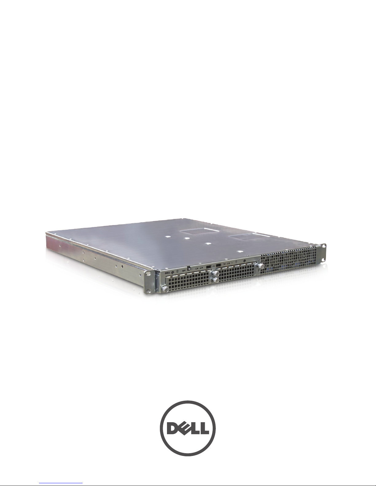
Dell DCS-1130
Setup and Features Information
Regulatory Model: FRG1
Page 2

Notes, Cautions, and Warnings
NOTE: A NOTE indicates important information that helps you make better use of your computer.
CAUTION: A CAUTION indicates either potential damage to hardware or loss of data and tells
you how to avoid the problem.
WARNING: A WARNING indicates a potential for property damage, personal injury or death.
––––––––––––––––––––––
Information in this document is subject to change without notice.
© 2011 Dell Inc. All rights reserved.
Reproduction of these materials in any manner whatsoever without the written permission of
Dell Inc. is strictly forbidden.
Trademarks used in this text: Dell™, the DELL logo are trademarks of Dell Inc. Intel® is a
registered trademarks or trademarks of Intel Corporation in the United States and other
countries. Red Hat® is a registered trademarks or trademarks of Red Hat, Inc. in the United States
and other countries.
Other trademarks and trade names may be used in this publication to refer to either the entities
claiming the marks and names or their products, Dell Inc. disclaims any proprietary interest in
trademarks and trade names other than its own.
Regulatory Model: FRG1
Regulatory Type: FRG1001
July 2011 - Rev. A00
Dell Part Number: HCT3M
Page 3

Dell DCS-1130 Setup and Features Information
Contents | Page 3
Contents
Notes, Cautions, and Warnings .............................................................................2
Accessing System Features During Startup ........................................................4
Figure 1. Front Panel .....................................................................................5
Hard-Drive Indicator Patterns ................................................................................6
Figure 2. Hard Drive Indicators ...................................................................6
Table 1. Hard Drive Indicator Status ..........................................................6
Back-Panel Features and Indicators ...................................................................7
Figure 3. Back Panel .....................................................................................7
NIC Indicator Codes .................................................................................................8
Figure 4. NIC Indicators ...............................................................................8
Figure 5. NIC Indicators (KVM over IP Port) .............................................9
Power and System Board Indicator Codes ........................................................10
Figure 6. System Identification and Power Indicators .........................10
Table 2. Status Indicator Codes ................................................................10
Power Supply Indicator Codes ............................................................................11
Figure 7. Power Supply Status Indicator ................................................11
Other Information You May Need .......................................................................11
Contacting Dell .......................................................................................................12
Page 4
Dell DCS-1130 Setup and Features Information
Page 4 | Accessing System Features During Startup
Accessing System Features During Startup
e following keystrokes provide access to system features during startup.
Keystroke Description
<F2> Enters the System Setup program.
<F11> Enters the BIOS Boot Manager.
<F12> Starts Preboot eXecution Environment (PXE) boot.
<Ctrl><C> Enters the SAS Conguration Utility.
<Ctrl><H> Enters the RAID conguration utility.
<Ctrl><S> Enters the utility to congure NIC settings for PXE boot. For more
information, see the documentation for your integrated NIC.
Page 5
Dell DCS-1130 Setup and Features Information
Accessing System Features During Startup | Page 5
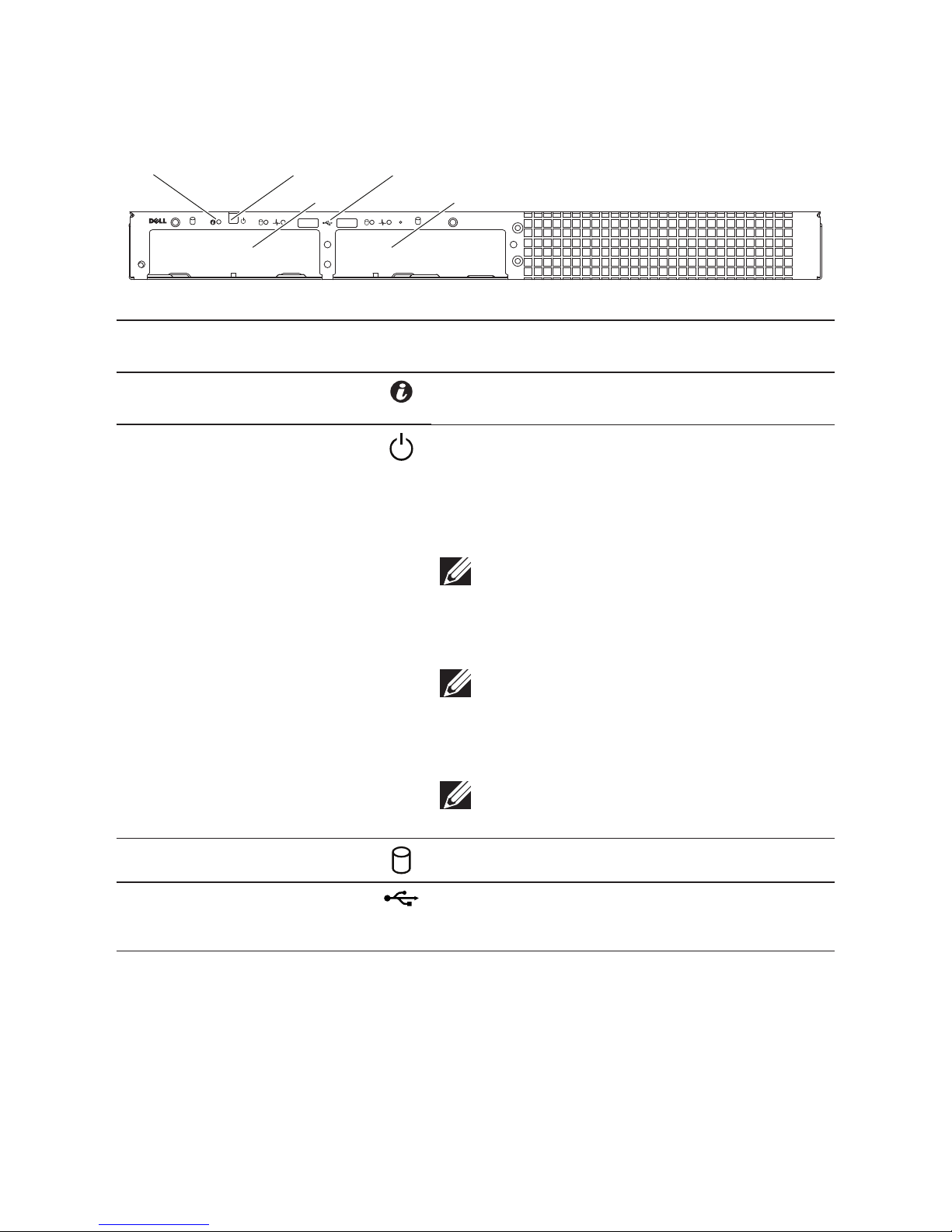
Front-Panel Features and Indicators
Figure 1. Front Panel
10
1
2 4
33
Item Indicator, Button, or
Connector
Icon Description
1 System identication
indicator
e identication LED can be used to locate a
particular system
2 Power-on indicator/
power button
e power-on indicator lights when the system
power is on.
e power button controls the DC power supply
output to the system.
NOTE: When powering on the system, the video
monitor can take from several seconds to over
2 minutes to display an image, depending on the
amount of memory installed in the system.
NOTE: On ACPI-compliant operating systems,
turning off the system using the power button
causes the system to perform a graceful shutdown before power to the system is turned off.
NOTE: To force an ungraceful shutdown, press
and hold the power button for 5 seconds.
3 Hard drives Hot-swappable hard drives
4 USB connectors (2) Connect USB devices to the system.
e ports are USB 2.0-compliant
Page 6
Dell DCS-1130 Setup and Features Information
Page 6 | Hard-Drive Indicator Patterns
Hard-Drive Indicator Patterns
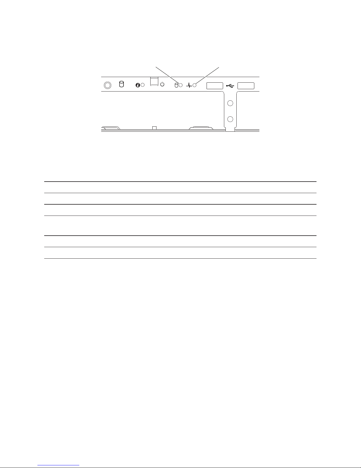
Figure 2. Hard Drive Indicators
0
1
2
1. hard-drive activity indicator
(green)
2. hard-drive status indicator
(green and amber)
Table 1. Hard Drive Indicator Status
Drive-Status Indicator Pattern Condition
O Slot empty
Solid green Hard drive online/access
Blinks green Hard drive rebuilding/ hard drive identication/preparing
for removal
Blinks green/amber Rebuild abort
Blinks amber Hard drive failed
Page 7
Dell DCS-1130 Setup and Features Information
Back-Panel Features and Indicators | Page 7
Back-Panel Features and Indicators
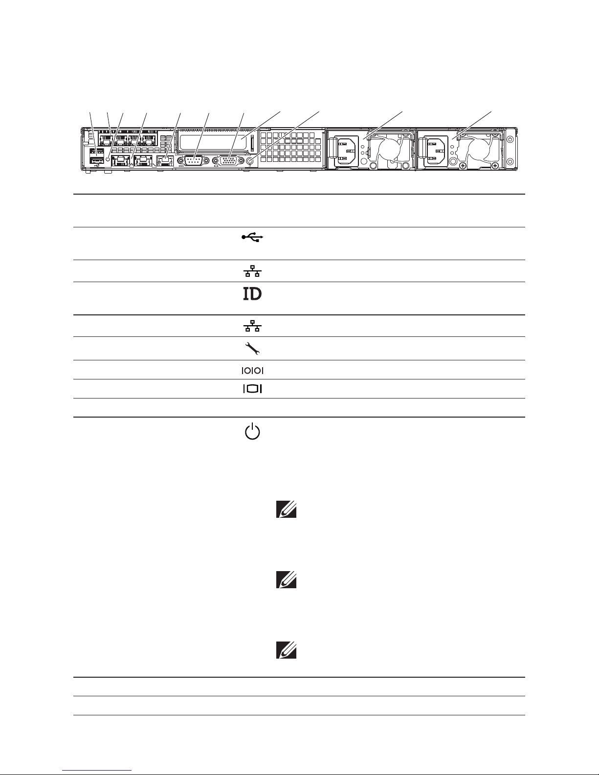
Figure 3. Back Panel
1 2
ID
31 4 5 6 7
11109
8
2
Item Indicator, Button, or
Connector
Icon Description
1 USB connectors (2) Connect USB devices to the system. e ports are
USB 2.0-compliant.
2 RJ-45 (4) Embedded 10/100/1000 NIC connectors.
3 System identication
indicator
Lights amber when the system needs attention due
to a problem.
4 Ethernet connectors (2) Embedded 10/100/1000 NIC connectors.
5 KVM over IP Port Dedicated management port.
6 Serial connector Connects a serial device to the system.
7 Video connector Connects a VGA display to the system.
8 Single channel optic interface In PCIe slot.
9 Power-on indicator/
power button
e power-on indicator lights when the system
power is on.
e power button controls the DC power supply
output to the system.
NOTE: When powering on the system, the video
monitor can take from several seconds to over
2 minutes to display an image, depending on the
amount of memory installed in the system.
NOTE: On ACPI-compliant operating systems,
turning off the system using the power button
causes the system to perform a graceful shutdown before power to the system is turned off.
NOTE: To force an ungraceful shutdown, press
and hold the power button for five seconds.
10 Power supply 2 (PS2) 470W
11 Power supply 1 (PS1) 470W
Page 8
Dell DCS-1130 Setup and Features Information
Page 8 | NIC Indicator Codes
NIC Indicator Codes
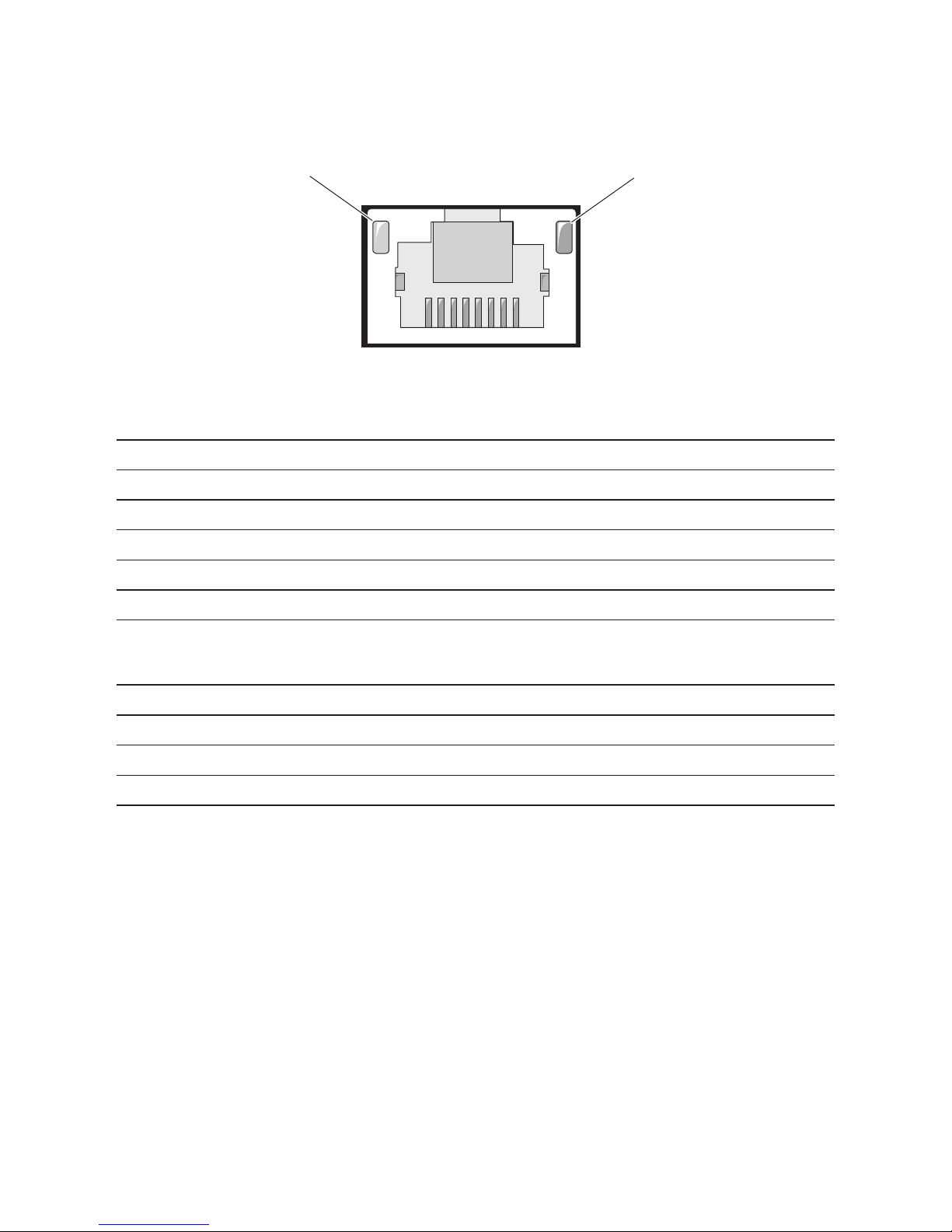
Figure 4. NIC Indicators
1
2
1. link indicator 2. activity indicator
NIC Status Indicator (link) Condition
Steady amber Link at 1 Gbps speed
Blinks amber Identifying port with 1 Gbps connection
Steady green Link at 100 Mbps speed
Blinks green Identifying port with 10 Mbps or 100 Mbps connection
O Link at 10 Mbps speed
NIC Status Indicator (activity) Condition
Steady green Link LAN / No access
Blinks green Accessing LAN
O Idle
Page 9
Dell DCS-1130 Setup and Features Information
NIC Indicator Codes | Page 9
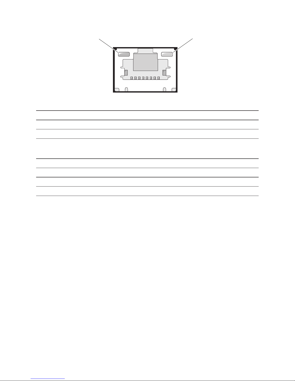
Figure 5. NIC Indicators (KVM over IP Port)
1
2
1. link indicator 2. activity indicator
NIC Status Indicator (link) Condition
Steady green Link at 100 Mbps speed
O Link at 10 Mbps speed
NIC Status Indicator (activity) Condition
Steady green Link LAN / No access
Blinks green LAN access
Green o Idle
Page 10
Dell DCS-1130 Setup and Features Information
Page 10 | Power and System Board Indicator Codes
Power and System Board Indicator Codes
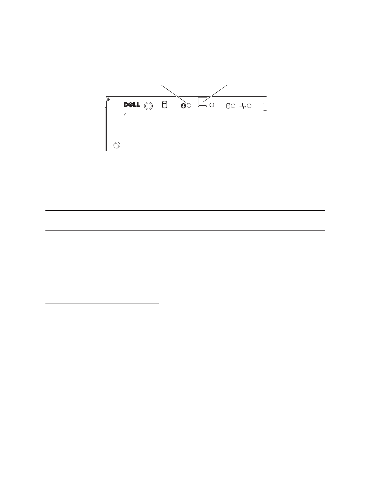
e LEDs on the system front panel and back panel display status codes during system startup.
Figure 6. System Identification and Power Indicators
0
1
2
1. system identification indicator 2. power-on indicator
Table 2 lists the status associated with the status codes.
Table 2. Status Indicator Codes
Component Indicator Condition
System
identication
indicator
Steady Blue
Blinks Blue
O
IPMI Via Chassis Identify Command On
Only IPMI using Chassis Identify Command Blink On
IPMI using Chassis Identify Command O
Power-on
indicator
Steady Green
Blinks Amber
Blinks Green/
Amber
Power On S0/S1
BMC Critical condition event in Power O mode S4/S5
BMC Critical condition event in Power On mode S0/S1
Page 11
Dell DCS-1130 Setup and Features Information
Power Supply Indicator Codes | Page 11
Power Supply Indicator Codes
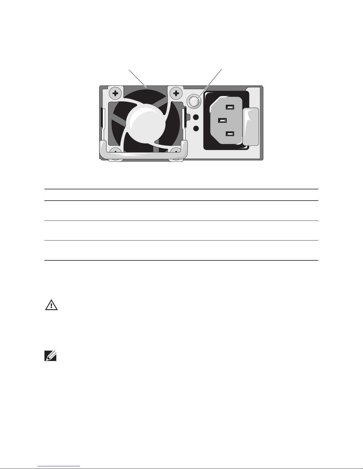
Figure 7. Power Supply Status Indicator
1
2
1. power supply 2. power supply indicator
Power Supply Status Indicator Condition
Steady green Power supply is on (AC OK/DC OK) or in standby mode
(90 VAC–264 VAC)
Steady yellow Power supply faulty (UVP/OVP/OCP/SCP/OTP/Fan
Fault)
Yellow o Power supply is o or AC input voltage is out of normal
operating range (90 VAC–264 VAC)
Other Information You May Need
WARNING: See the safety and regulatory information that shipped with your system. Warranty
information may be included within this document or as a separate document.
e Getting Started Guide provides an overview of rack installation, system features, setting up
your system, and technical specications.
NOTE: Always check for updates on support.dell.com/manuals and read the updates first be-
cause they often supersede information in other documents.
Page 12

Dell DCS-1130 Setup and Features Information
Page 12 | Contacting Dell
Contacting Dell
For customers in the United States, call 800-WWW-DELL (800-999-3355).
NOTE: If you do not have an active Internet connection, you can find contact information on your
purchase invoice, packing slip, bill, or Dell product catalog.
Dell provides several online and telephone-based support and service options. Availability varies
by country and product, and some services may not be available in your area. To contact Dell for
sales, technical support, or customer service issues:
1 Visit support.dell.com
2 Verify your country or region in the Choose A Country/Region drop-down menu at the
bottom of the page.
3 Click Contact Us on the le side of the page.
4 Select the appropriate service or support link based on your need.
5 Choose the method of contacting Dell that is convenient for you.
 Loading...