

Page 1

Alienware AW3423DW Monitor
User’s Guide
Monitor Model: AW3423DW
Regulatory Model: AW3423DWb
Page 2
Notes, cautions, and warnings
NOTE: A NOTE indicates important information that helps you make
better use of your computer.
CAUTION: A CAUTION indicates potential damage to hardware or loss
of data if instructions are not followed.
WARNING: A WARNING indicates a potential for property damage,
personal injury, or death.
© 2022 Dell Inc. or its subsidiaries. All rights reserved. Dell, EMC, and other trademarks are
trademarks of Dell Inc. or its subsidiaries. Other trademarks may be trademarks of their respective
owners.
2022 - 11
Rev. A04
Page 3

Contents
Safety instructions . . . . . . . . . . . . . . . . . . . . . . . . . . . . . . 6
About your monitor . . . . . . . . . . . . . . . . . . . . . . . . . . . . . 7
Package contents . . . . . . . . . . . . . . . . . . . . . . . . . . . . . . . . . . . . 7
Product features . . . . . . . . . . . . . . . . . . . . . . . . . . . . . . . . . . . . . 9
Identifying parts and controls . . . . . . . . . . . . . . . . . . . . . . . . . 10
Front view . . . . . . . . . . . . . . . . . . . . . . . . . . . . . . . . . . . . . . . . . . . . . . . . .10
Top view . . . . . . . . . . . . . . . . . . . . . . . . . . . . . . . . . . . . . . . . . . . . . . . . . . .11
Back view. . . . . . . . . . . . . . . . . . . . . . . . . . . . . . . . . . . . . . . . . . . . . . . . . . 11
Rear and bottom view . . . . . . . . . . . . . . . . . . . . . . . . . . . . . . . . . . . . . . .12
Monitor specifications . . . . . . . . . . . . . . . . . . . . . . . . . . . . . . . 15
Resolution specifications . . . . . . . . . . . . . . . . . . . . . . . . . . . . . 17
Supported video modes . . . . . . . . . . . . . . . . . . . . . . . . . . . . . . . . . . . . . .17
HDMI preset display modes . . . . . . . . . . . . . . . . . . . . . . . . . . . . . . . . . .17
Electrical specifications . . . . . . . . . . . . . . . . . . . . . . . . . . . . . . . . . . . . . .19
Physical characteristics . . . . . . . . . . . . . . . . . . . . . . . . . . . . . . . . . . . . . 20
Environmental characteristics . . . . . . . . . . . . . . . . . . . . . . . . . . . . . . . . .21
Pin assignments . . . . . . . . . . . . . . . . . . . . . . . . . . . . . . . . . . . . . . . . . . . 22
Plug-and-Play capability . . . . . . . . . . . . . . . . . . . . . . . . . . . . . 23
Universal Serial Bus (USB) interface . . . . . . . . . . . . . . . . . . . 24
USB 3.2 Gen 1 (5 Gbps) upstream connector . . . . . . . . . . . . . . . . . . 24
USB 3.2 Gen 1 (5 Gbps) downstream connector. . . . . . . . . . . . . . . . 25
USB ports. . . . . . . . . . . . . . . . . . . . . . . . . . . . . . . . . . . . . . . . . . . . . . . . . 25
QD-OLED monitor quality and pixel policy . . . . . . . . . . . . . 26
Ergonomics. . . . . . . . . . . . . . . . . . . . . . . . . . . . . . . . . . . . . . . . . 26
Handling and moving your display . . . . . . . . . . . . . . . . . . . . . 28
Maintenance guidelines . . . . . . . . . . . . . . . . . . . . . . . . . . . . . . 29
Cleaning your monitor . . . . . . . . . . . . . . . . . . . . . . . . . . . . . . . . . . . . . . 29
|3
Page 4

Setting up the monitor. . . . . . . . . . . . . . . . . . . . . . . . . . 31
Attaching the stand. . . . . . . . . . . . . . . . . . . . . . . . . . . . . . . . . . 31
Connecting the computer. . . . . . . . . . . . . . . . . . . . . . . . . . . . 35
Removing the monitor stand . . . . . . . . . . . . . . . . . . . . . . . . . 36
Attaching the VESA adapter (optional). . . . . . . . . . . . . . . . 38
Operating the monitor. . . . . . . . . . . . . . . . . . . . . . . . . . 39
Turn on the monitor . . . . . . . . . . . . . . . . . . . . . . . . . . . . . . . . . 39
Using the joystick . . . . . . . . . . . . . . . . . . . . . . . . . . . . . . . . . . 39
Using the On-Screen Display (OSD) menu . . . . . . . . . . . . . 40
Accessing the Menu Launcher . . . . . . . . . . . . . . . . . . . . . . . . . . . . . . . .40
Accessing the menu system . . . . . . . . . . . . . . . . . . . . . . . . . . . . . . . . . .42
OSD warning message . . . . . . . . . . . . . . . . . . . . . . . . . . . . . . . . . . . . . .57
Setting the maximum resolution . . . . . . . . . . . . . . . . . . . . . . .61
Using the tilt, swivel, and vertical extension . . . . . . . . . . . . 62
Tilt and swivel extensions . . . . . . . . . . . . . . . . . . . . . . . . . . . . . . . . . . . .62
Vertical extension . . . . . . . . . . . . . . . . . . . . . . . . . . . . . . . . . . . . . . . . . .62
Using AlienFX application. . . . . . . . . . . . . . . . . . . . . . . 63
Prerequisites . . . . . . . . . . . . . . . . . . . . . . . . . . . . . . . . . . . . . . 63
Installing AWCC through Windows update . . . . . . . . . . . . 63
Installing AWCC from the Dell Support website . . . . . . . . 63
Navigating the AlienFX window . . . . . . . . . . . . . . . . . . . . . . 64
Creating a theme . . . . . . . . . . . . . . . . . . . . . . . . . . . . . . . . . . . 66
Setting lighting effects . . . . . . . . . . . . . . . . . . . . . . . . . . . . . . 67
Troubleshooting . . . . . . . . . . . . . . . . . . . . . . . . . . . . . . . 72
Self-test. . . . . . . . . . . . . . . . . . . . . . . . . . . . . . . . . . . . . . . . . . . 72
Built-in diagnostics . . . . . . . . . . . . . . . . . . . . . . . . . . . . . . . . . .73
Common problems. . . . . . . . . . . . . . . . . . . . . . . . . . . . . . . . . . 74
Product specific problems . . . . . . . . . . . . . . . . . . . . . . . . . . . 77
Universal Serial Bus (USB) specific problems . . . . . . . . . . . 80
4|
Page 5

Appendix . . . . . . . . . . . . . . . . . . . . . . . . . . . . . . . . . . . . . 81
FCC notices (U.S. only) and other regulatory
information. . . . . . . . . . . . . . . . . . . . . . . . . . . . . . . . . . . . . . . . . 81
Contact Dell. . . . . . . . . . . . . . . . . . . . . . . . . . . . . . . . . . . . . . . . 81
EU product database for energy label and product
information sheet . . . . . . . . . . . . . . . . . . . . . . . . . . . . . . . . . . . 81
|5
Page 6

Safety instructions
WARNING: Use of controls, adjustments, or procedures other than those
specified in this documentation may result in exposure to shock, electrical
hazards, and/or mechanical hazards.
• Place the monitor on a solid surface and handle it carefully. The screen is
fragile and can be damaged if dropped or hit sharply.
• Always be sure that your monitor is electrically rated to operate with the
AC power available in your location.
• Keep the monitor in room temperature. Excessive cold or hot conditions
can have an adverse effect on the liquid crystal of the display.
• Do not subject the monitor to severe vibration or high impact conditions.
For example, do not place the monitor inside a car trunk.
• Unplug the monitor when it is going to be left unused for an extended
period of time.
• To avoid electric shock, do not attempt to remove any cover or touch the
inside of the monitor.
For information on safety instructions, see the Safety, Environmental, and
Regulatory Information (SERI) document.
6 | Safety instructions
Page 7
About your monitor
Package contents
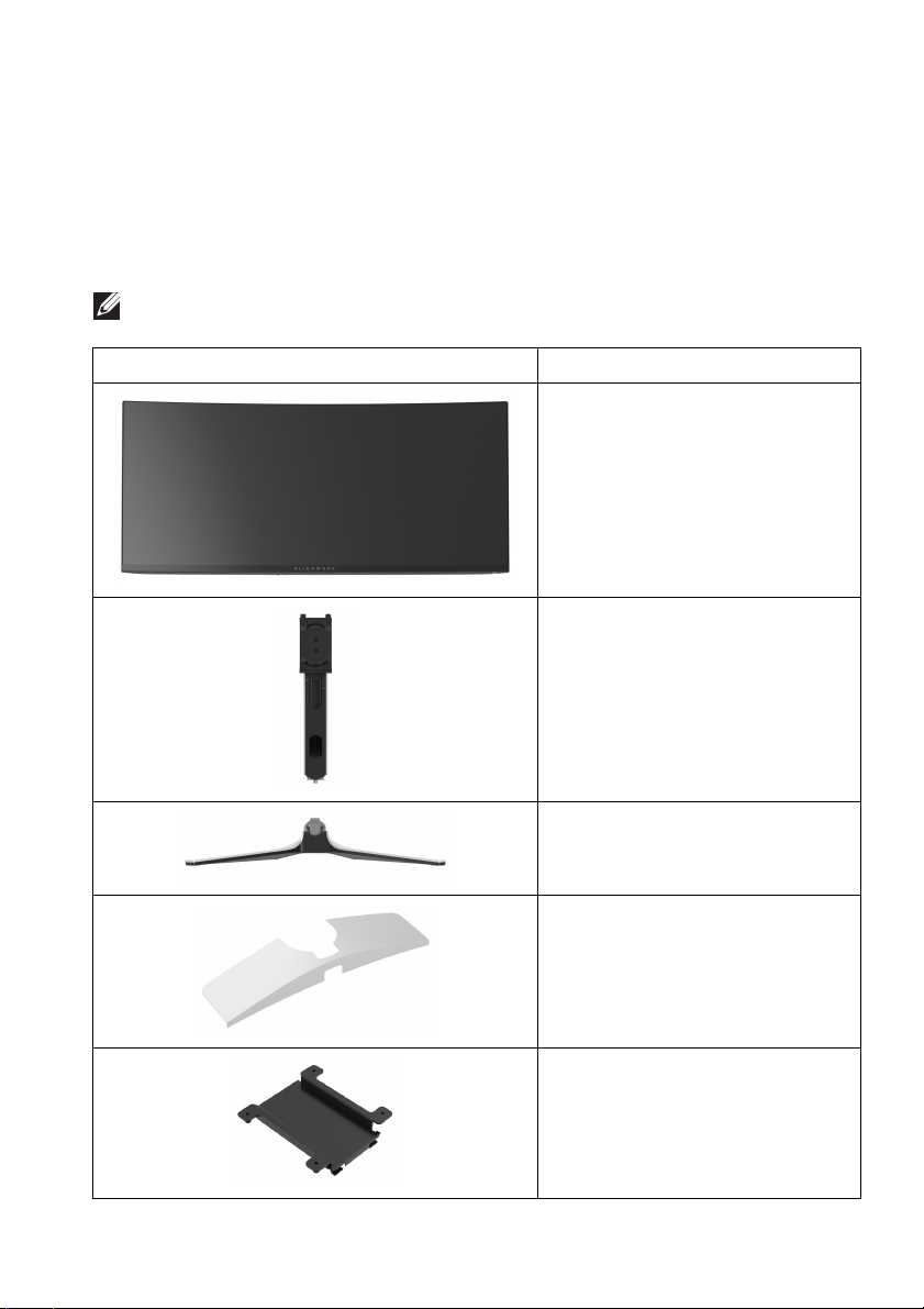
Your monitor ships with the components shown in the following table. If any
component is missing, contact Dell technical support. For more information, see
Contact Dell.
NOTE: Some components may be optional and may not ship with your
monitor. Some features or media may not be available in certain countries.
Component image Component description
Display
Stand riser
Stand base
I/O cover
VESA adapter
About your monitor | 7
Page 8
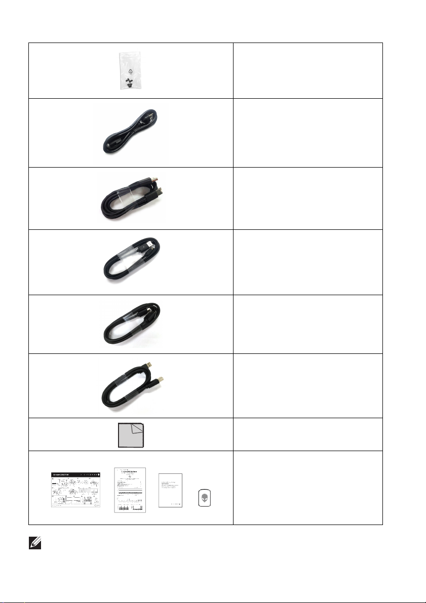
Screw (M4) x 4
(for locking a purchased wall-
mount
the VESA adapter)
Power cable (varies by country)
DisplayPort to DisplayPort 1.4
cable (1.8 meters)
Mini-DisplayPort to DisplayPort
1.4 cable (1.8 meters)
HDMI 2.0 cable (1.8 meters)
kit or 3rd-party arm on
NOTE: Monitors shipped from October 2022 wi
sticker instead of an Alienware welcome card.
8 | About your monitor
USB 3.2 Gen 1 (5 Gbps)
upstream cable (enables the
USB ports on the monitor,
1.8 meters)
Microfiber cloth
• Quick Start Guide
• Factory calibration report
• Safety, Environmental, and
Regulatory Information
• Alienware Sticker
ll include an Alienware
Page 9

Product features
The Alienware AW3423DW is a Quantum Dot-Organic Light Emitting Diode
(QD-OLED) display that uses Oxide TFT as active element. The monitor features
include:
• 86.82 cm (34.18 in.) viewable area (measured diagonally). Resolution: Up
to 3440 x 1440 through DisplayPort and HDMI, with full-screen support or
lower resolutions, supporting a high refresh rate of 175
• NVIDIA G-SYNC ULTIMATE certified monitor that delivers tear free,
stutter free and ultra-low latency gameplay.
• Color gamut of 149% sRGB and DCI-P3 99.3%.
• Tilt, swivel, and height adjustment capabilities.
• Removable stand and Video Electronics Standards Association (VESA)
mounting holes (100 mm x 100 mm) using VESA adapter for flexible
mounting solutions.
• Digital connectivity through 1 DisplayPort and 2 HDMI ports.
• The monitor is equipped with:
- One SuperSpeed USB 5 Gbps (USB 3.2 Gen 1) Type B upstream port
- One SuperSpeed USB 5 Gbps (USB 3.2 Gen 1) Type-A downstream
charging port
- Three SuperSpeed USB 5 Gbps (USB 3.2 Gen 1) Type-A downstream
ports
• Plug-and-play capability if supported by your computer.
• On-Screen Display (OSD) adjustments for ease of setup and screen
optimization.
• AW3423DW offers a couple of preset modes for user's own preference,
including:
-Creator
- First-Person Shooter (FPS)
- Multiplayer Online Battle Arena/Real-Time Strategy (MOBA/RTS)
- Role-Playing Game (RPG)
- Racing (SPORTS)
- Three customizable game modes
In addition, key enhanced gaming features such as Timer, Frame Rate, and
Display Alignment are provided to help improve gamer's performance and
provide best-in game advantage.
• Security-lock slot.
Hz.
About your monitor | 9
Page 10
• Power consumption
• VESA DisplayHDR 400 True Black.
• Optimize eye comfort with a flicker-free
• The Monitor uses Low Blue Light panel and is compliant with TÜV
Rheinland (Ha
in low blue light solution reduces hazardous blue light emissions by
adjusting display parameters, without sacrificing true-to-life colors.
< 0.5 W in Standby Mode.
screen and low blue light feature.
rdware Solution) at factory reset or default setting. This built-
WARNING: The possible long-term effec
the monitor may cause damage to the eyes, including eye fatigue, digital
eye strain, and so on. ComfortView Plus feature is designed to reduce the
amount of blue light emitted from the monitor to optimize eye comfort.
ts of blue light emission from
Identifying parts and controls
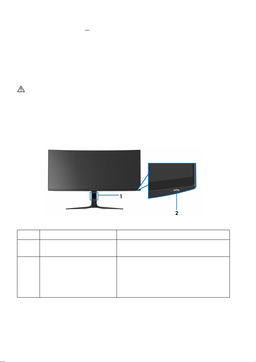
Front view
Label Description Use
1 Cable-management slot (on
the front side
2 Power button (with LED
indi
cator)
of the stand)
To organize the cables neatly.
To turn the monitor on or off.
Solid blue light indicates that the monitor
is turned
Blinking white light indicates that the
monitor is in Standby Mode.
on and functioning normally.
10 | About your monitor
Page 11
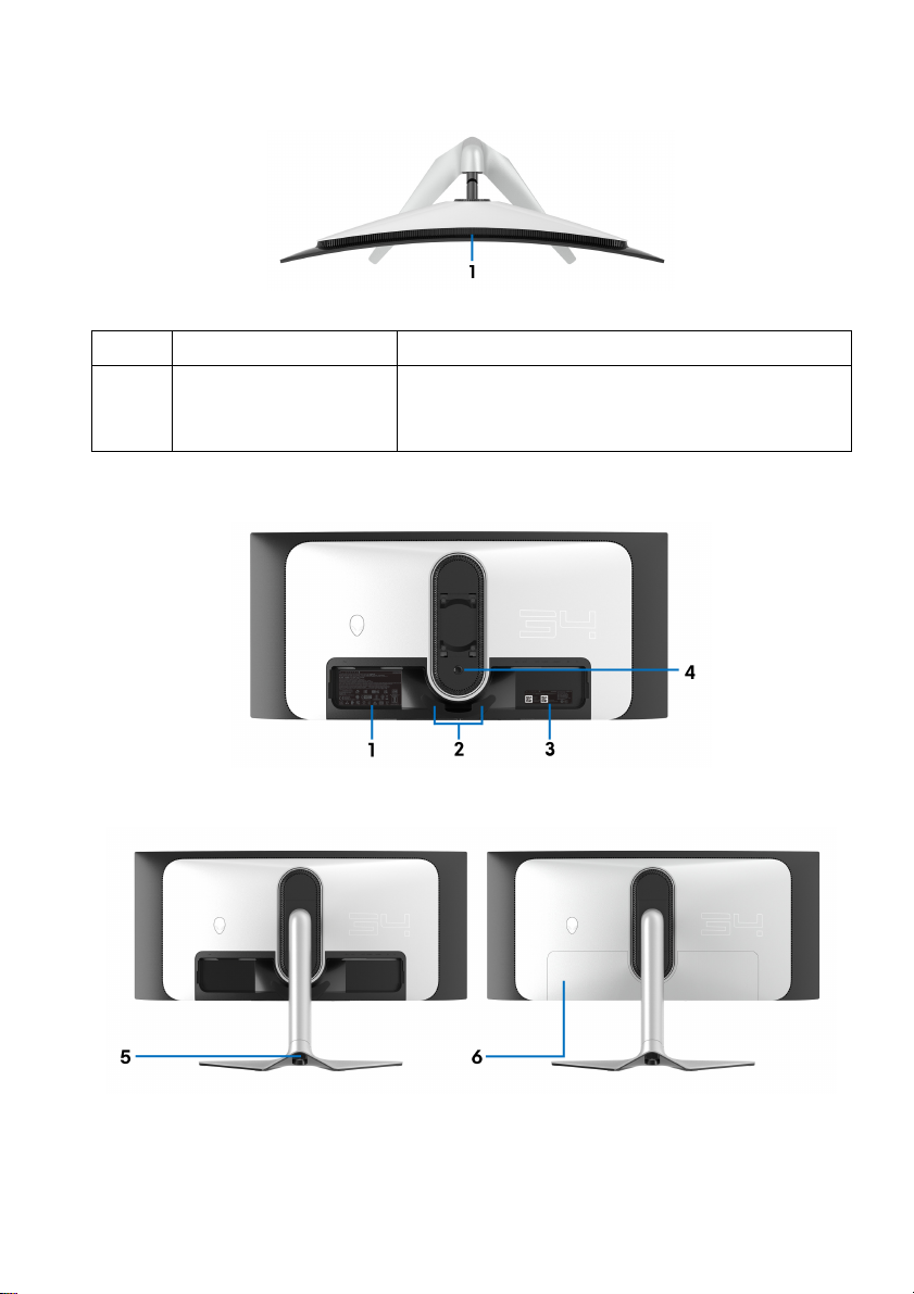
Top view
Label Description Use
1 Ambient light sensor Detects ambient light and adjusts the
bri
ghtness of the display accordingly. For more
information, see Ambient Light Sensor.
Back view
Back view without monitor stand
Back view with monitor stand
About your monitor | 11
Page 12
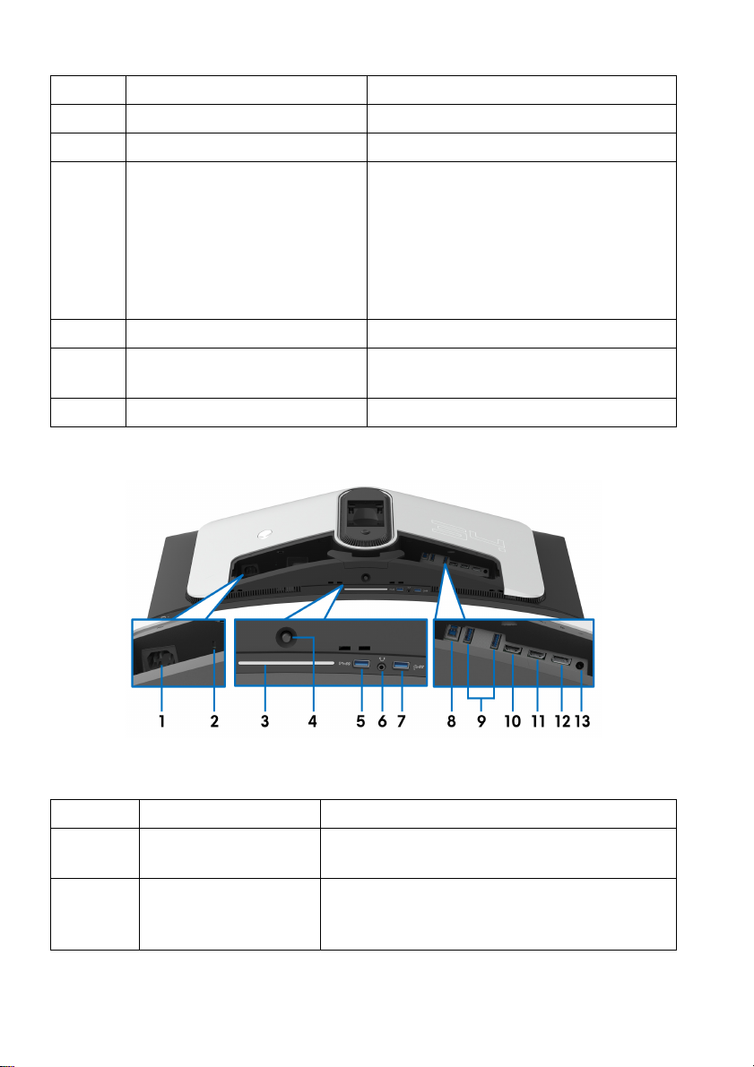
Label Description Use
1 Regulatory label Lists the regulatory approvals.
2 Cable-management clips (2) To organize the cables neatly.
3 Barcode, serial number, and
Servic
e Tag label
4 Stand release button Releases the stand from the monitor.
5 Cable-management slot (at
e back of the stand)
th
6 I/O cover Protects the I/O ports.
Rear and bottom view
See this label if you need to contact
Dell for technical support. The Service
Tag is a unique alphanumeric identifier
that enables Dell service technicians to
identify the hardware components in
your monitor and access warranty
information.
To organize cables by routing them
through this slot.
Rear and bottom view without monitor stand
Label Description Use
1 Power connector Connect the power cable (shipped with your
2 Security-lock slot
(based on
Security Slot)
12 | About your monitor
Kensington
monitor
Secure the monitor with a security lock
(security lock not included).
).
Page 13
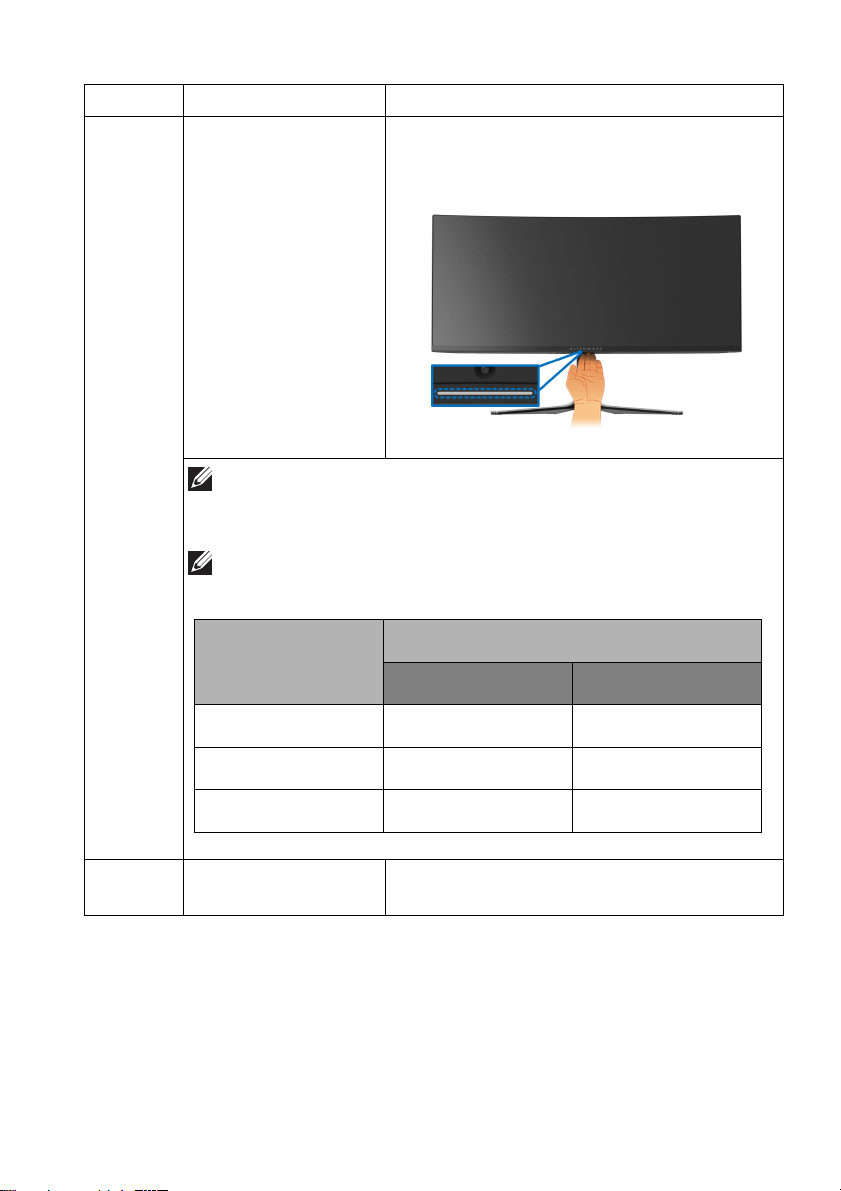
Monitor state
Downlights status
When Lighting Effects is
deactivated
When Lighting Effects is
activated
On Enabled Disabled
No Signal Enabled Disabled
Standby Disabled Disabled
Label Description Use
3 Downlights When the monitor setup is complete, tap the
touch sens
or at the bottom of the display to
turn the downlights on or off.
NOTE: The factory setting is on, so the downlights are active
if the power cable is connected. To change the default
settings, see AlienFX Lighting.
NOTE: When Lighting Effects, such as Spectrum, Comet, or
Rainbow Cycle, is activated, the downlights are turned off.
4 Joystick Use it to control the OSD menu. For more
information, see Operating the monitor.
About your monitor | 13
Page 14
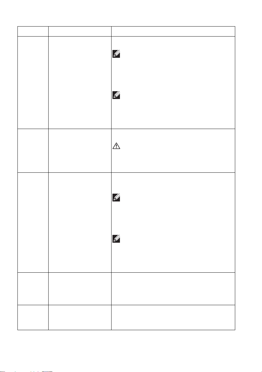
Label Description Use
5 SuperSpeed USB
5
Gbps (USB 3.2
Gen
1) Type-A
downstream port with
Power Charging
6 Headphone port Connect the headphone or speakers.
7, 9 SuperSpeed USB
5
Gbps (USB 3.2
Gen
1) Type-A
downstream port (3)
Connect to charge your USB device.
NOTE: To use this port, you must
connect the USB cable (shipped with
your monitor) to the USB-upstream
port on the monitor and to your
computer.
NOTE: To avoid signal interference,
when a wireless USB device has been
connected to a USB downstream port,
it is not recommended to connect any
other USB devices to the adjacent port.
WARNING: The possible long-term
effect of listening to audio at high
volume through the headphones may
cause damage to your hearing ability.
Connect your USB 3.2 Gen 1 (5 Gbps)
device.
NOTE: To use these ports, you must
connect the USB cable (shipped with
your monitor) to the USB-upstream
port on the monitor and to your
computer.
NOTE: To avoid signal interference,
when a wireless USB device is
connected to a USB downstream port,
it is not recommended to connect any
other USB devices to the adjacent port.
8 SuperSpeed USB
5
Gbps (USB 3.2
Gen
1) Type-B
upstream port
10 HDMI port (HDMI 1) Connect your computer with the HDMI
14 | About your monitor
Connect the USB cable (shipped with your
monitor) to this port and your computer to
enable the USB ports on your monitor.
cable (one HDMI cable is shipped with your
monitor).
Page 15
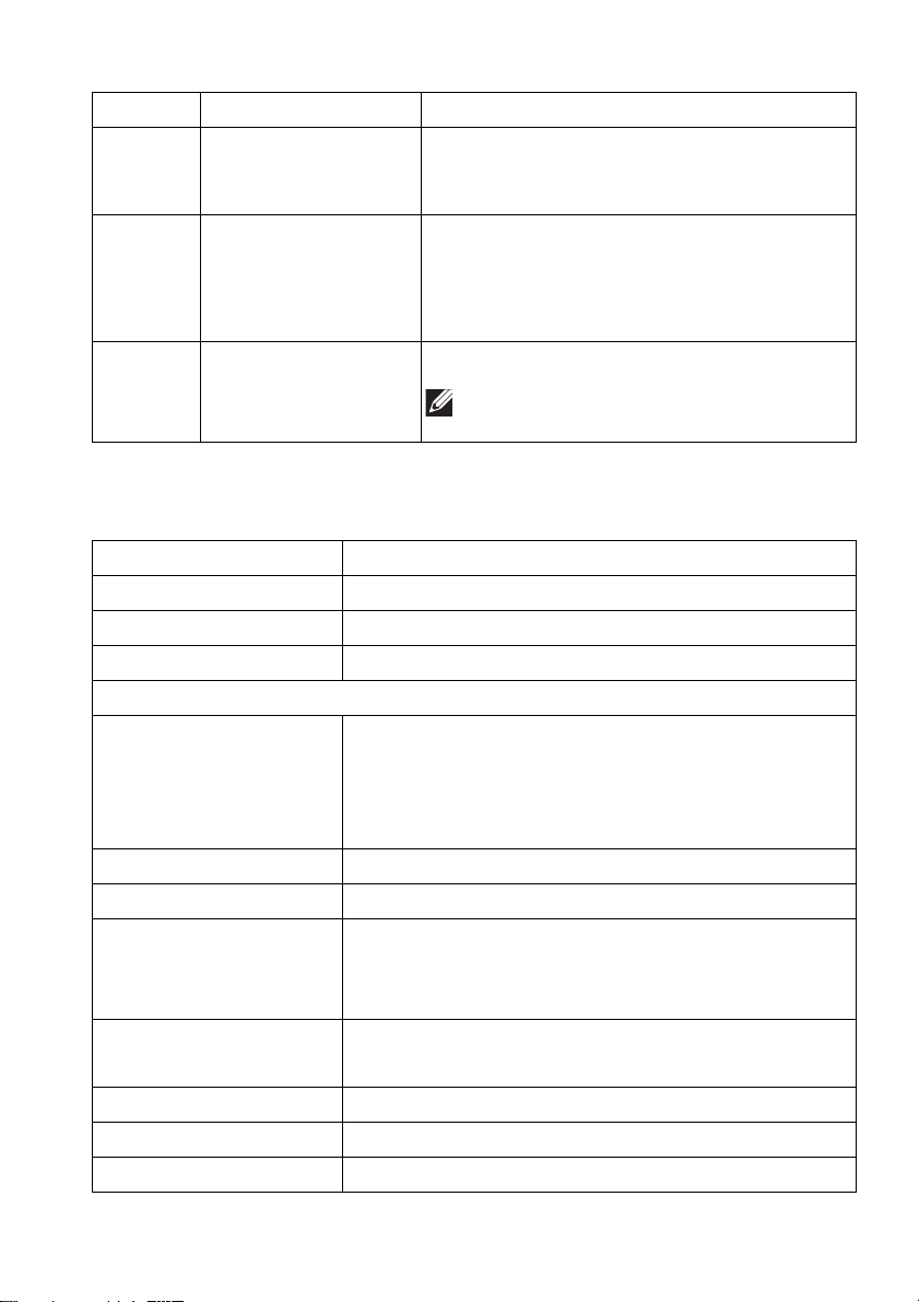
Label Description Use
11 HDMI port (HDMI 2) Connect your computer with the HDMI
cable (one HDMI cable is shipped with your
monitor).
12 DisplayPort Connect your computer with one of the
following cables shipped with your monitor:
• DisplayPort-DisplayPort cable
• Mini-DisplayPort-DisplayPort cable
13 Line-out port Connect your speakers.
NOTE: This port does not support
headphones.
Monitor specifications
Description Value
Screen type Color Active Matrix
Panel technology QD OLED
Aspect ratio 21:9
Viewable image
Diagonal:
Width (active area)
Height (active area)
Total area
Pixel pitch 0.23 mm x 0.23 mm
Pixel per inch (PPI) 110
Viewing angle:
Vertical
Horizontal
Luminance output 250 cd/m² (typical)
Contrast ratio 1 million: 1 at (SDR) and (HDR)
Faceplate coating Anti reflection
Backlight OLED
868.21 mm (34.18 in.)
800.10 mm (31.50 in.)
337.10 mm (13.27 in.)
269,713.71 mm2 (418.01 in.2)
178° (typical)
178° (typical)
1000 cd/m² (HDR peak)
About your monitor | 15
Page 16
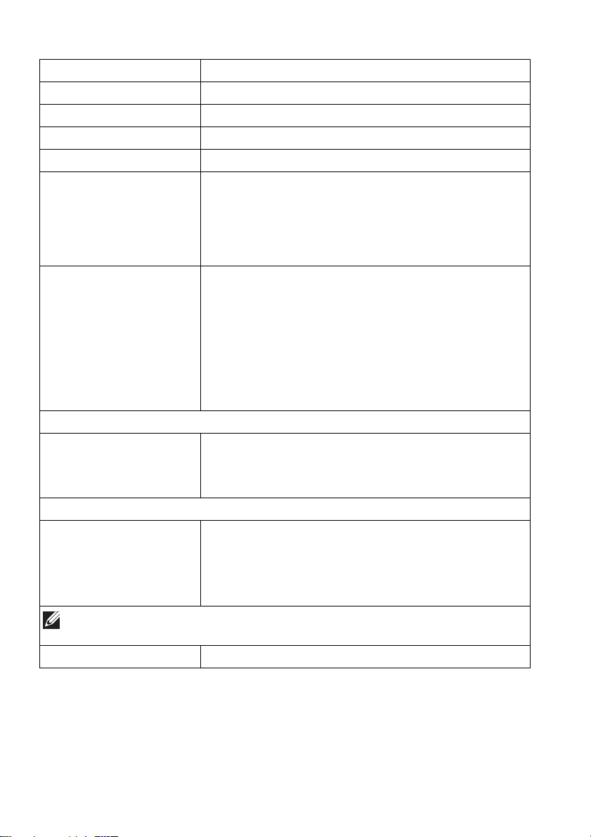
Description Value
Response time 0.1 ms gray-to-gray
Curvature 1800R (typical)
Color depth 1.07 billion colors (10 bit)
Color gamut 149% sRGB and DCI-P3 99.3%
Integrated devices • SuperSpeed USB 5 Gbps (USB 3.2 Gen 1) hub
(with one USB 3.2 Gen
• 4 x SuperSpeed USB 5 Gbps (USB 3.2 Gen 1)
downstream port (including 1 port which supports
power-charging)
Connectivity • 1 x DisplayPort version 1.4 with HDCP 2.2 (rear)
• 2 x HDMI port version 2.0 with HDCP 2.2 (rear)
• 1 x USB 3.2 Gen 1 (5 Gbps) upstream port (rear)
• 4 x USB 3.2 Gen 1 (5 Gbps) downstream ports
(bottom: 2; rear: 2)
• 1 x headphone port (bottom)
• 1 x audio line-out port (rear)
Border width (edge of monitor to active area)
Top
Left/Right
Bottom
Adjustability
Height adjustable stand
Tilt
Swivel
Slant adjust
NOTE: Do not mount or use this monitor in portrait (vertical) orientation
or inverse (180°) landscape mount as it may damage the monitor.
Security Security-lock slot (cable lock sold separately)
6.45 mm
10.99 mm/10.99 mm
20.60 mm
0 mm to 110 mm
-5° to 21°
-20° to 20°
-5° to 5°
1 (5 Gbps) upstream port)
16 | About your monitor
Page 17
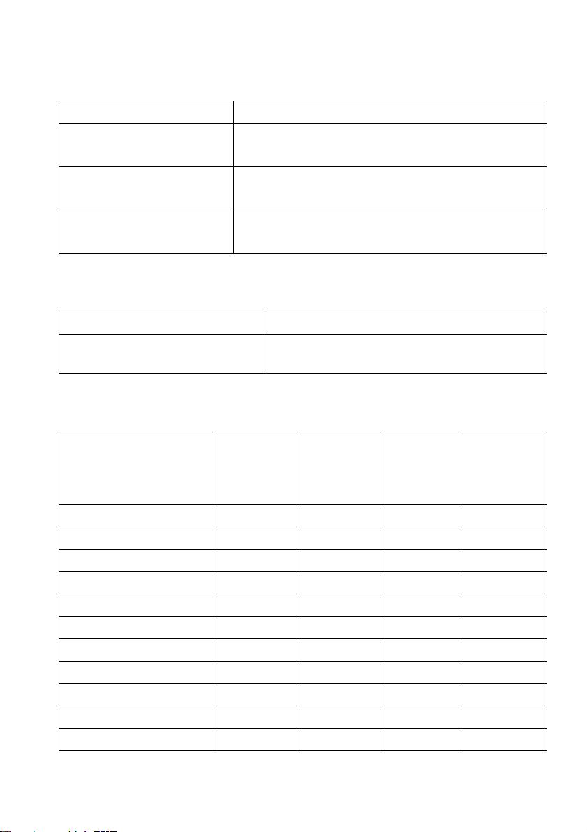
Resolution specifications
Description Value
Horizontal scan range •DisplayPort 1.4: 31 kHz to 274 kHz (automatic)
• HDMI 2.0: 30 kHz to 150 kHz (automatic)
Vertical scan range • DisplayPort 1.4: 1 Hz to 175 Hz (aut
• HDMI 2.0: 24 Hz to 120 Hz (automatic)
Maximum preset resolution • DisplayPort: 3440 x 1440 at 175 Hz
• HDMI: 3440 x 1440 at 100 Hz
Supported video modes
Description Value
Video display capabilities (HDMI
and Displ
HDMI preset display modes
ayPort playback)
480p, 576p, 720p, 1080p, QHD
omatic)
Display mode Horizontal
frequency
Hz)
(k
VESA, 640 x 480 31.50 59.90 25.20 -/-
800 x 600 37.90 60.30 40 +/+
VESA,
VESA, 1024 x 768 48.40 60 65 -/-
640 x 480p 31.48 60 25.18 -/720 x 480p 31.50 60 27.03 -/-
720 x 576p 31.25 50 27 -/1280 x 720p at 50 Hz 37.50 50 74.25 +/+
1280 x 720p at 60 Hz 45 60 74.25 +/+
1920 x 1080p at 50 Hz 56.25 50 148.50 +/+
1920 x 1080p at 60 Hz 67.50 60 148.50 +/+
1920 x 1080p at 120 Hz 135 120 297 +/+
Vertical
frequency
(Hz)
Pixel clock
(MHz)
About your monitor | 17
Sync
polarity
(Horizontal/
Vertical)
Page 18
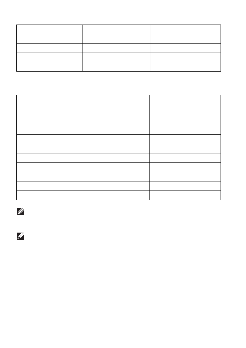
2560 x 1440 at 60 Hz
2560 x 1440 at 120 Hz 183 120 497.75 +/-
3440 x 1440 at 50 Hz 73.68 49.99 265.25 +/3440 x 1440 at 60 Hz 88.82 59.97 319.75 +/-
3440 x 1440 at 100 Hz 150.97 99.98 543.50 +/-
DisplayPort preset display modes
88.79 59.95 241.50 +/-
Display mode Horizontal
frequency
z)
(kH
VESA, 640 x 480 31.50 59.90 25.20 -/V
ESA, 800 x 600 37.90 60.30 40 +/+
VESA, 1024 x 768 48.40 60 65 -/-
3440 x 1440 at 60 Hz 88.82 59.97 319.75 +/3440 x 1440 at 100 Hz 150.97 99.98 543.50 +/3440 x 1440 at 120 Hz 182.98 119.99 658.74 +/3440 x 1440 at 144 Hz 222.15 143.97 799.74 +/3440 x 1440 at 175 Hz 274.16 174.96 986.99 +/-
NOTE: This monitor supports NVIDIA G-SYNC ULTIMATE. For more
information about the graphic cards that support NVIDIA G-SYNC
ULTIMATE feature, see www.geforce.com.
NOTE: To get the full NVIDIA G-SYNC ULTIMATE functionalities and
experience, ensure that the monitor is directly connected to the HDMI
port or DisplayPort with direct output from NVIDIA graphics card on
your computer.
Vertical
frequency
(Hz)
Pixel clock
(MHz)
Sync
polarity
(Horizontal/
Vertical)
18 | About your monitor
Page 19
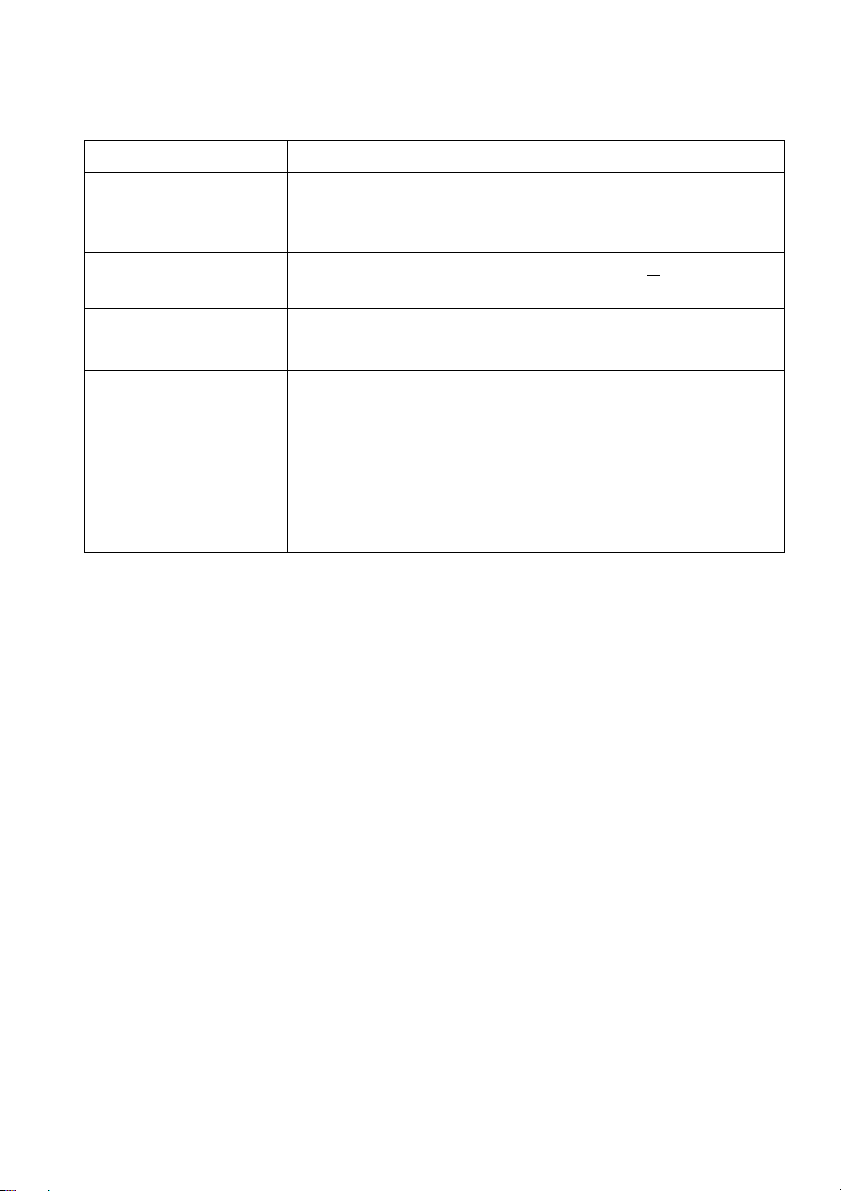
Electrical specifications
Description Value
Video input signals HDMI 2.0/DisplayPort 1.4, 600 mV for each
di
fferential line, 100 Ω input impedance per differential
pair
AC input voltage/
frequency/current
100 VAC to 240 VAC/50 Hz or 60 Hz
(typical)
+ 3 Hz/3 A
Inrush current • 120 V: 40 A (maximum) at 0°C (cold start)
• 240 V: 80 A (maximum) at 0°C (cold start)
Power consumption • 0.3 W (Off mode)
• 0.5 W (Standby Mode)
• 42.3 W (On mode)
•200 W (Max.)
•47.6 W (Pon)
•149.8 kWh (TEC)
1
As defined in EU 2019/2021 and EU 2019/2013.
2
Maximum brightness and contrast setting with maximum power loading on all
1
1
1
2
3
3
USB ports.
3 Pon
: Power consumption of On Mode measured with reference to Energy Star
test method.
TEC: Total Energy Consumption in kWh measured with reference to Energy
Star test method.
This document is informational only and reflects laboratory performance. Your
product may perform differently, depending on the software, components and
peripherals you ordered and shall have no obligation to update such
information.
Accordingly, the customer should not rely upon this information in making
decisions about electrical tolerances or otherwise. No warranty as to accuracy
or completeness is expressed or implied.
About your monitor | 19
Page 20
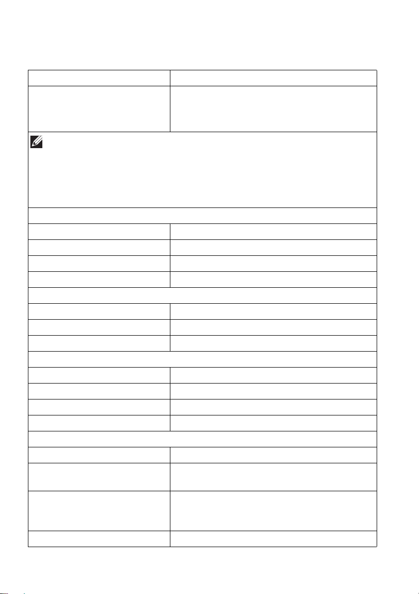
Physical characteristics
Description Value
Sign
al cable type
NOTE: Dell monitors are designed to work optimally
cables that are shipped with your monitor. As Dell does not have control
over different cable suppliers in the market, the type of material,
connector, and process used to manufacture these cables, Dell does not
guarantee video performance of cables that are not shipped with your
Dell monitor.
Dimensions (with stand):
Height (extended) 525.57 mm (20.69 in.)
Height (compressed) 415.57 mm (16.36 in.)
Width 815.25 mm (32.10 in.)
Depth 305.71 mm (12.04 in.)
Dimensions (without stand):
Height 364.15 mm (14.34 in.)
Width 815.25 mm (32.10 in.)
Depth 137.11 mm (5.40 in.)
Stand dimensions:
Height (extended) 411.81 mm (16.21 in.)
Height (compressed) 382.13 mm (15.04 in.)
Width 430.72 mm (16.96 in.)
Depth 305.71 mm (12.04 in.)
Weight:
Weight with packaging 15.90 kg (35.05 lb)
Weight with stand assembly
a
nd cables
Weight without stand assembly
(For
wall mount or VESA mount
considerations - no cables)
Weight of stand assembly 2.96 kg (6.53 lb)
• Digital: HDMI, 19 pins
• Digital: DisplayPort, 20 pins
• Universal Serial Bus: USB, 9 pins
with the video
10.37 kg (22.86 lb)
6.92 kg (15.26 lb)
20 | About your monitor
Page 21
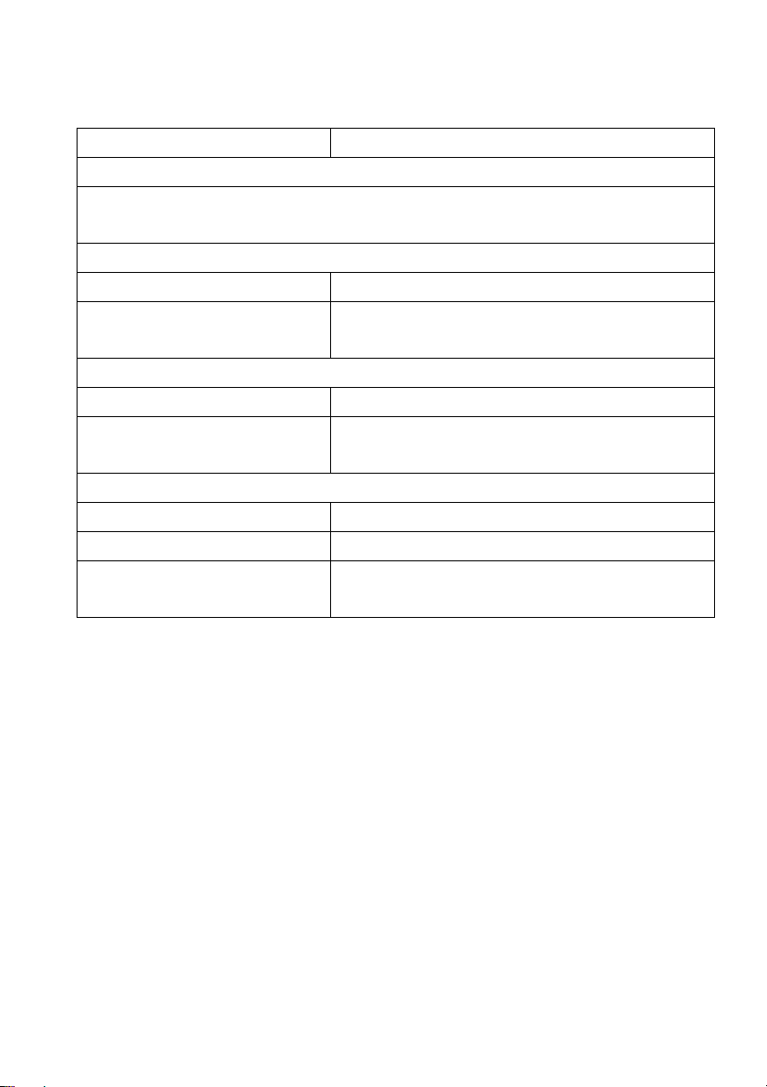
Environmental characteristics
Description Value
Complian
• RoHS-compliant
• Arsenic-free glass and mercury-free for the panel only
Temperature:
Operating 0°C to 40°C (32°F to 104°F)
Non-operating • Storage: -20°C to 60°C (-4°F to 140°F)
Humidity:
Operating 10% to 80% (non-condensing)
Non-operating • Storage: 10% to 90% (non-condensing)
Altitude:
Operating 5,000 m (16,404 ft) (maximum)
Non-operating 12,192 m (40,000 ft) (maximum)
Thermal dissipation
t standards
• Shipping: -20°C to 60°C (-4°F to 140°F)
• Shipping: 10% to 90% (non-condensing)
•684 BTU/hour (maximum)
• 144.67 BTU/hour (
typical)
About your monitor | 21
Page 22
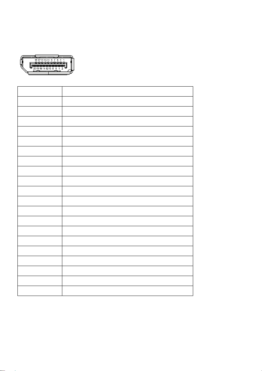
Pin assignments
DisplayPort connector
Pin number 20-pin side of the connected signal cable
1ML3 (n)
2GND
3ML3 (p)
4ML2 (n)
5GND
6ML2 (p)
7ML1 (n)
8GND
9ML1 (p)
10 ML0 (n)
11 GND
12 ML0 (p)
13 GND
14 GND
15 AUX (p)
16 GND
17 AUX (n)
18 Hot Plug Detect
19 Re-PWR
20 +3.3 V DP_PWR
22 | About your monitor
Page 23
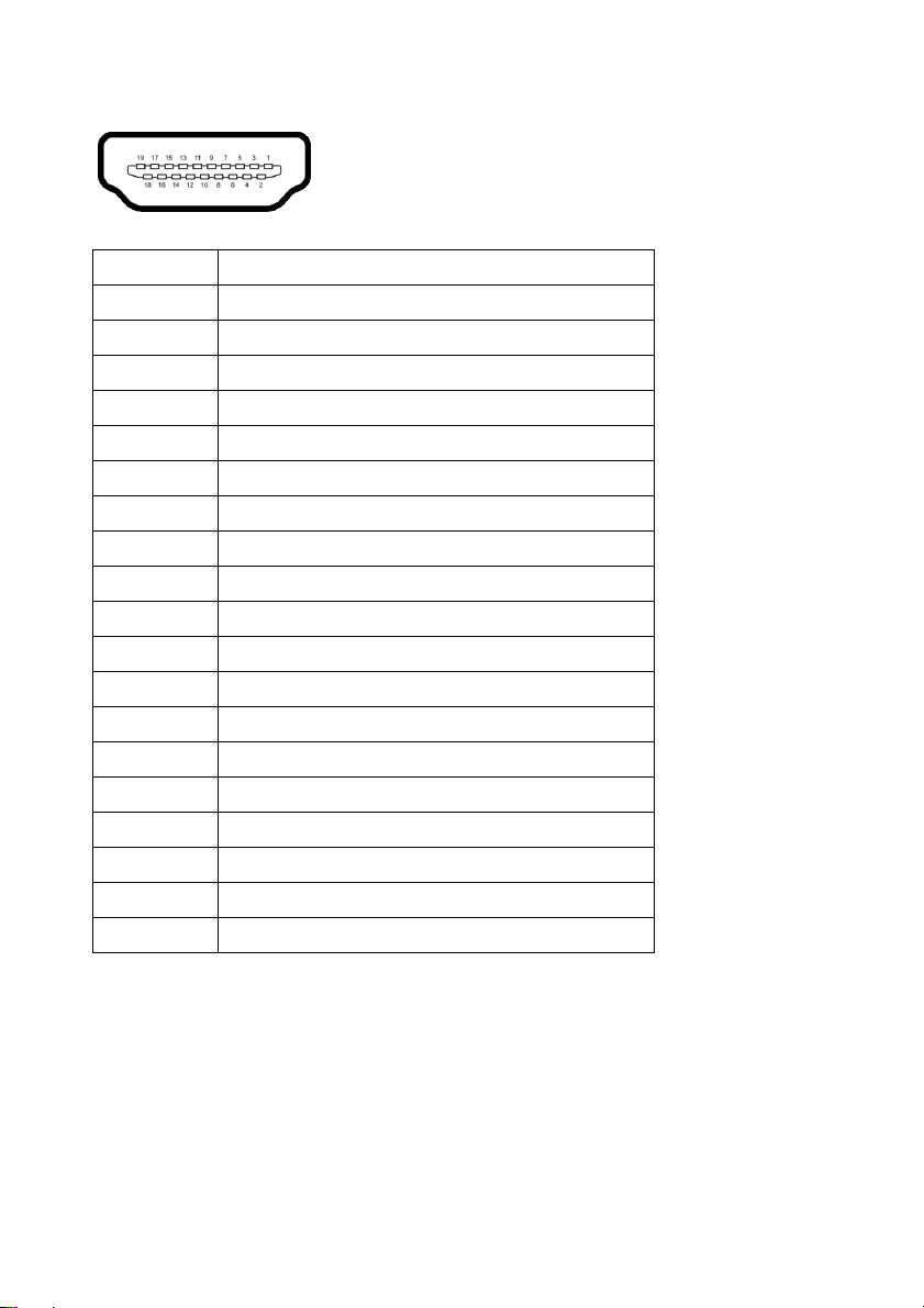
HDMI connector
Pin number 19-pin side of the connected signal cable
1T
2 TMDS DATA 2 SHIELD
3TMDS DATA 24TMDS DATA 1+
5 TMDS DATA 1 SHIELD
6TMDS DATA 1-
7TMDS DATA 0+
8 TMDS DATA 0 SHIELD
9TMDS DATA 0-
10 TMDS CLOCK+
11 TMDS CLOCK SHIELD
12 TMDS CLOCK13 CEC
14 Reserved (N.C. on device)
15 DDC CLOCK (SCL)
16 DDC DATA (SDA)
17 DDC/CEC Ground
18 +5 V POWER
19 HOT PLUG DETECT
MDS DATA 2+
Plug-and-Play capability
You can connect the monitor to any Plug-and-Play compatible computer. The
monitor automatically provides the computer with its Extended Display
Identification Data (EDID) using Display Data Channel (DDC) protocols so that
the computer can configure itself and optimize the monitor settings. Most
monitor installations are automatic; you can select different settings, if required.
For more information about changing the monitor settings, see Operating the
monitor.
About your monitor | 23
Page 24
Universal Serial Bus (USB) interface
This section provides information about the USB ports that are available on the
monitor.
NOTE: This monitor is SuperSpeed USB 5 Gbps (USB 3.2 Gen 1)
compatible.
Transfer speed Data rate Power consumption*
Super-Speed 5 Gbps 4.5 W (maximum each port)
High speed 480 Mbps 4.5 W (maximum each port)
Full speed 12 Mbps 4.5 W (maximum each port)
*Up to 2 A on USB downstream port (with battery icon) with battery charging
version-compliant devices or normal USB devices.
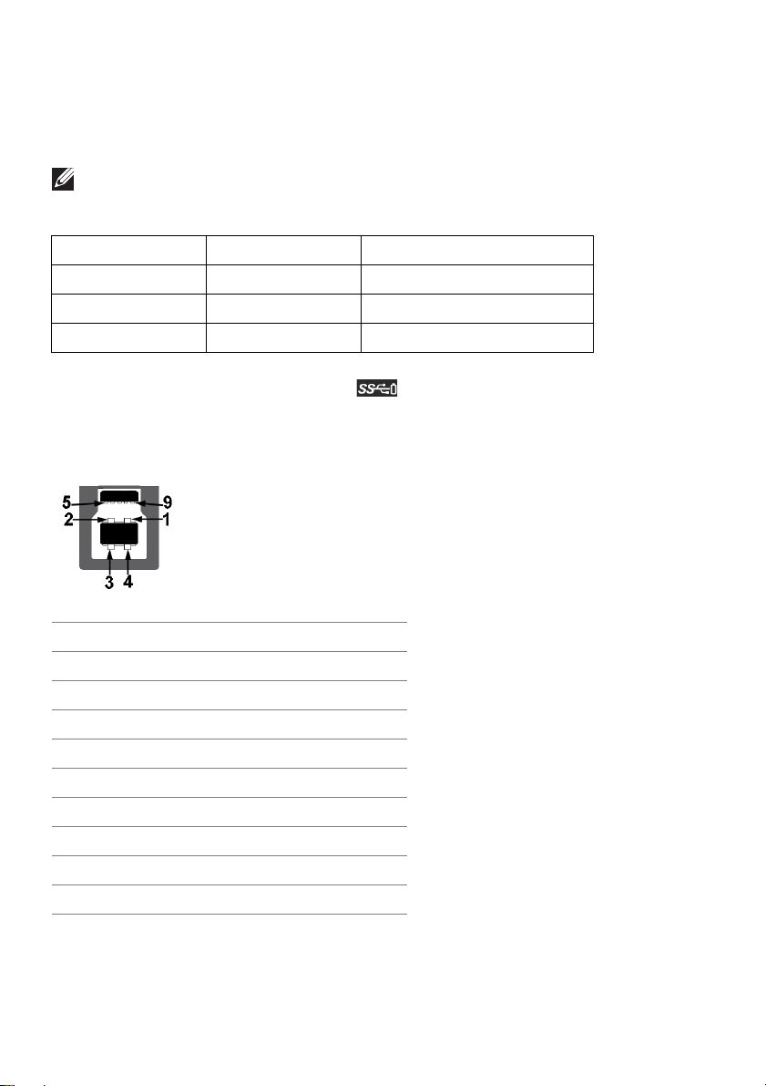
USB 3.2 Gen 1 (5 Gbps) upstream connector
Pin number 9-pin side of the connector
1VCC
2D-
3D+
4GND
5 SSTX6 SSTX+
7GND
8 SSRX9 SSRX+
24 | About your monitor
Page 25
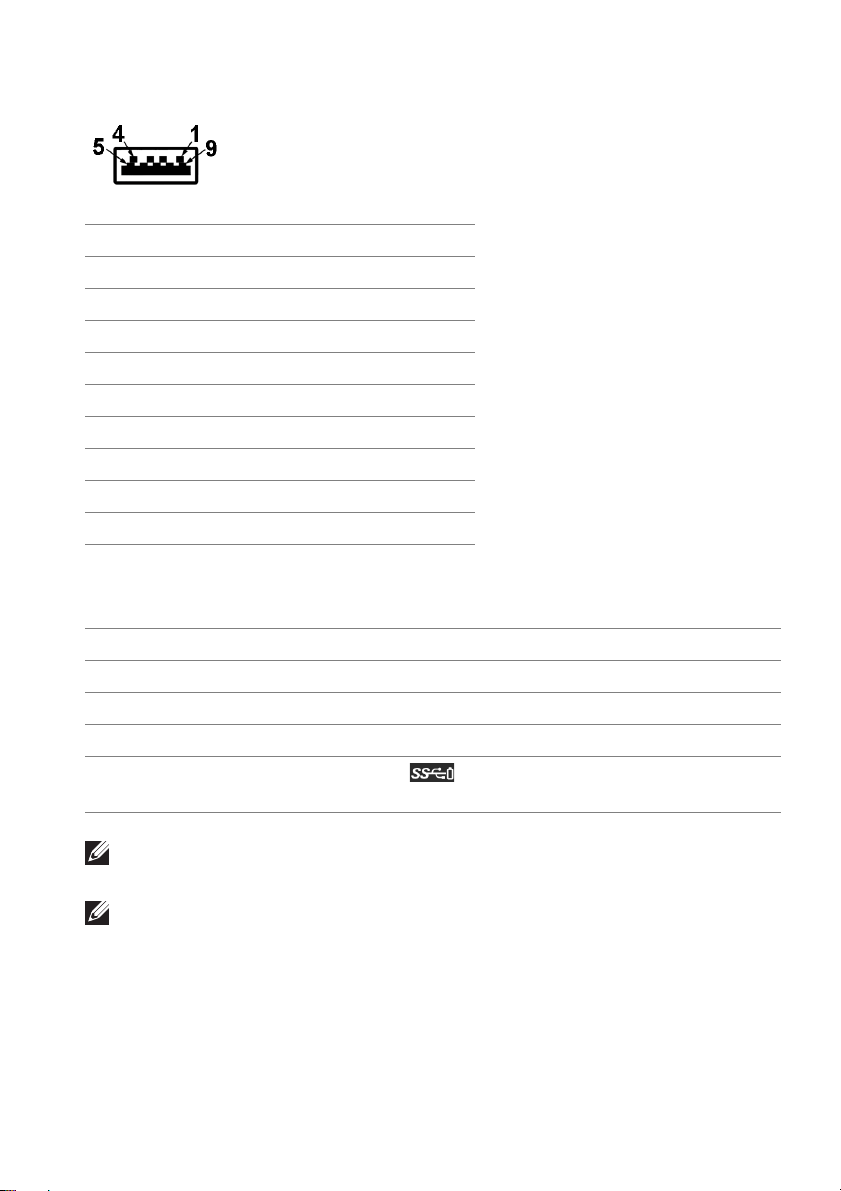
USB 3.2 Gen 1 (5 Gbps) downstream connector
Pin number 9-pin side of the connector
1V
2D-
3D+
4GND
5SSRX6SSRX+
7GND
8SSTX9SSTX+
USB ports
Port Location
1 x upstream rear
2 x downstream rear
2 x downstream bottom
Power charging port - the port with
charging capability if the device is BC1.2 compatible.
CC
icon; supports up to 2 A fast-
NOTE: SuperSpeed USB 5 Gbps (USB 3.2 Gen 1) functionality requires a
SuperSpeed USB 5 Gbps (USB 3.2 Gen 1)-capable computer.
NOTE: The USB ports on the monitor work only when the monitor is
turned on or in Standby mode. If you turn off the monitor and then turn it
on, the attached devices may take a few seconds to resume normal
functionality.
About your monitor | 25
Page 26

QD-OLED monitor quality and pixel policy
During the QD-OLED monitor manufacturing process, it is not uncommon for
one or more pixels to become fixed in an unchanging state, which are hard to
see and do not affect the display quality or usability. For more information about
Dell Monitor Quality and Pixel Policy, see
www.dell.com/pixelguidelines.
Ergonomics
CAUTION: Improper or prolonged usage of keyboard may result in
injury.
CAUTION: Viewing the monitor screen for extended periods of time may
result in eye strain.
For comfort and efficiency, observe the following guidelines when setting up
and using your computer workstation:
• Position your computer so that the monitor and keyboard are directly in
front of you as you work. Special shelves are commercially available to help
you correctly position your keyboard.
• To reduce the risk of eye strain and neck/arm/back/shoulder pain from
using the monitor for long periods of time, we suggest you to:
1. Set the distance of the screen between 20 to 28 in. (50 - 70 cm) from
your eyes.
2. Blink frequently to moisten your eyes or wet your eyes with water after
prolonged usage of the monitor.
3. Take regular and frequent breaks for 20 minutes every two hours.
4. Look away from your monitor and gaze at a distant object at 20 feet
away for at least 20 seconds during the breaks.
5. Perform stretches to relieve tension in the neck, arm, back, and shoulders
during the breaks.
• Ensure that the monitor screen is at eye level or slightly lower when you are
sitting in front of the monitor.
• Adjust the tilt of the monitor, its contrast, and brightness settings.
• Adjust the ambient lighting around you (such as overhead lights, desk
lamps, and the curtains or blinds on nearby windows) to minimize
reflections and glare on the monitor screen.
• Use a chair that provides good lower-back support.
• Keep your forearms horizontal with your wrists in a neutral, comfortable
position while using the keyboard or mouse.
• Always leave space to rest your hands while using the keyboard or mouse.
26 | About your monitor
Page 27
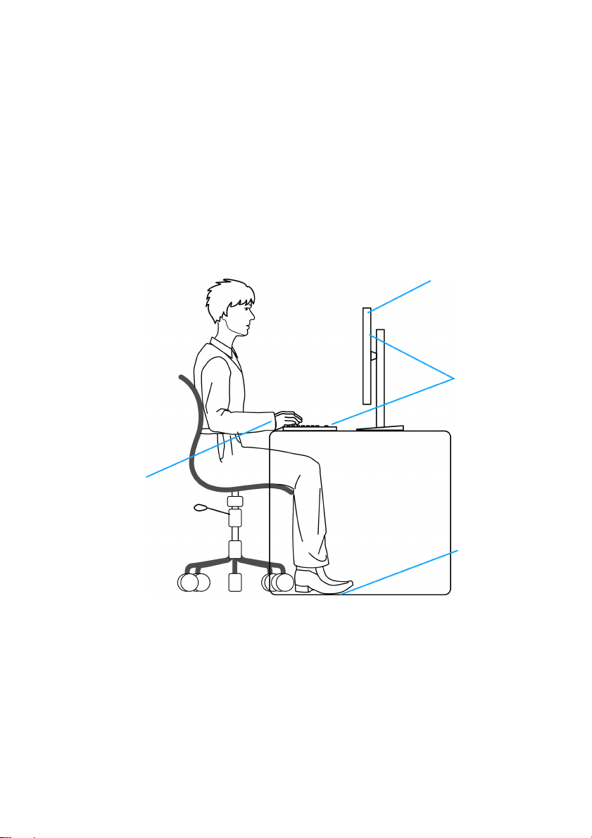
• Let your upper arms rest naturally on both sides.
Monitor screen at or
below eye level
Monitor and
keyboard
positioned
directly in front
of the user
Feet flat on
the floor
Wrists relaxed
and flat
• Ensure that your feet are resting flat on the floor.
• When sitting, make sure that the weight of your legs is on your feet and not
on
the front portion of your seat. Adjust your chair's height or use a footrest
if necessary to maintain a proper posture.
• Vary your work activities. Try to organize your work so that you do not have
t and work for extended periods of time. Try to stand or get up and
to si
walk around at regular intervals.
• Keep the area under your desk clear of obstructi
ons and cables or power
cords that may interfere with comfortable seating or present a potential trip
hazard.
About your monitor | 27
Page 28
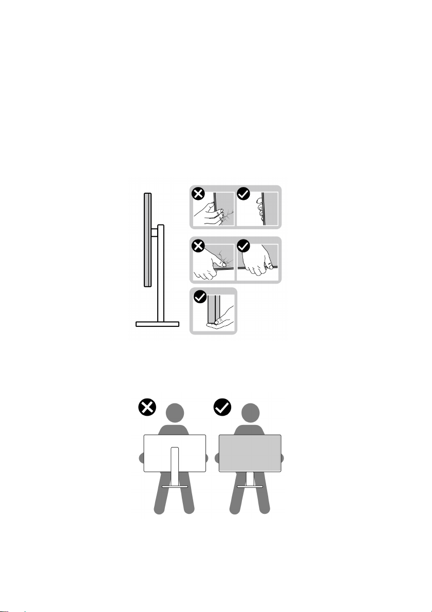
Handling and moving your display
To ensure that the monitor is handled safely when lifting or moving it, follow the
guidelines mentioned below:
• Before moving or lifting the monitor, tur
monitor.
• Disconnect all cables from the monitor.
• Place the monitor in the original box wi
• Hold the bottom edge and the side of t
excessive pressure when lifting or moving the monitor.
n off your computer and the
th the original packing materials.
he monitor firmly without applying
• When lifting or moving the monitor, ensure that the screen is facing away
from you and do not press on the display area to avoid any scratches or
damage.
• When transporting the monitor, avoid any sudden shock or vibration to it.
28 | About your monitor
Page 29
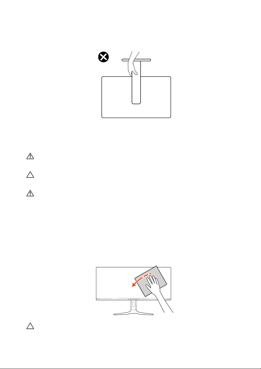
• When lifting or moving the monitor, do not turn the monitor upside down
while holding the stand base or stand riser. This may result in accidental
damage to the monitor or cause personal injury.
Maintenance guidelines
Cleaning your monitor
WARNING: Using improper methods when cleaning the
result in a physical damage to the screen or the body of your Dell monitor.
CAUTION: Read and follow the Safety instructions before cleaning the
monitor.
WARNING: Before cleaning the monitor, unplug the monitor power
cable from the electrical outlet.
For best practices, follow the instructions
cleaning, or handling your monitor:
• To clean the Dell monitor screen, lightl
water. If possible, use a special screen-cleaning tissue or solution suitable
for the Dell Monitor screen.
• Using available dry cloth, gently wipe the
time to remove stain and dust.
CAUTION: Do not use detergents or other chemicals such as benzene,
thinner, ammonia, abrasive cleaners, or compressed air.
in the list below when unpacking,
y dampen a soft, clean cloth with
film surface in one direction at a
monitor can
About your monitor | 29
Page 30
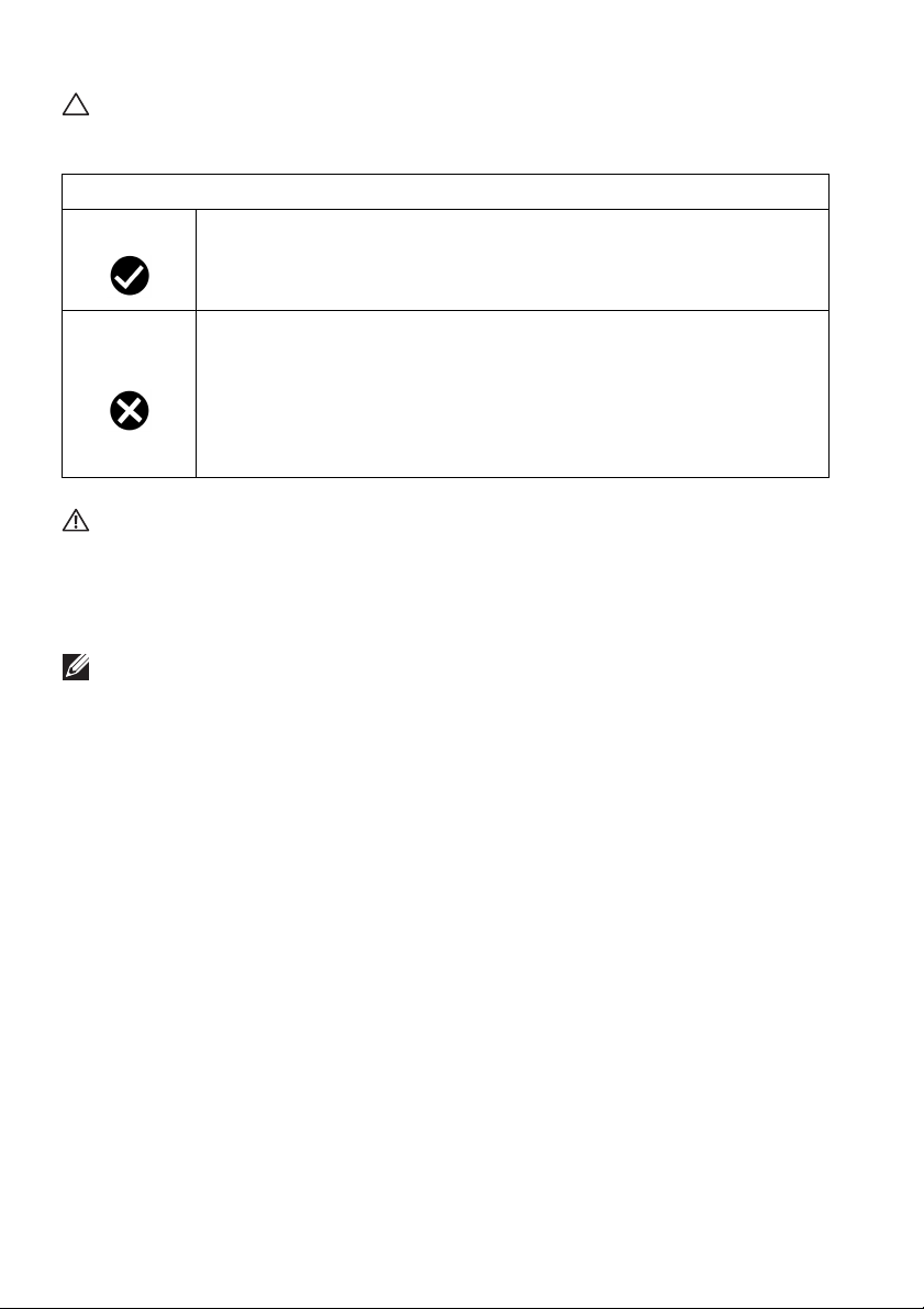
CAUTION: Using chemicals for cleaning may cause changes in the
appearance of the monitor, such as color fading, milky film on the monitor,
deformation, uneven dark shade, and peeling of screen area.
Cleaner
Do use • Filtered or distilled water
• Neutral or alkali detergent (for example, dish soap) with water
• LCD/LED screen cleaner (without Acetone)
• Toluene/Acetone/Solvent
Don’t use
WARNING: Do not spray the cleaning solution or even water directly on
the monitor surface. Doing so will allow liquids to accumulate at the
bottom of the display panel and corrode the electronics resulting in
permanent damage. Instead, apply the cleaning solution or water to a soft
cloth and then clean the monitor.
NOTE: Monitor damage due to improper cleaning methods and the use of
benzene, thinner, ammonia, abrasive cleaners, alcohol, compressed air,
detergent of any kind will lead to a Customer Induced Damage (CID).
CID is not covered under the standard Dell warranty.
• If you notice white powder when you unpack your monitor, wipe it off with
a cloth.
• Handle your monitor with care as a darker-colored monitor may get
scratched and show white scuff marks more than a lighter-colored monitor.
• To help maintain the best image quality on your monitor, use a dynamically
changing screen saver and turn off your monitor when not in use.
• Common glass cleaner
• Household cleaning products
• Abrasive cleaning solution
• Cleaner containing hydrogen peroxide
30 | About your monitor
Page 31
Setting up the monitor
Attaching the stand
NOTE: The stand is not factory-installed.
NOTE: The following instructions are only applicable for the stand that
was shipped with your monitor. If you are attaching a stand that you
purchased from any other source, follow the setup instructions that were
included with the stand.
CAUTION: The following steps are important
screen. Follow the instructions to complete the installation.
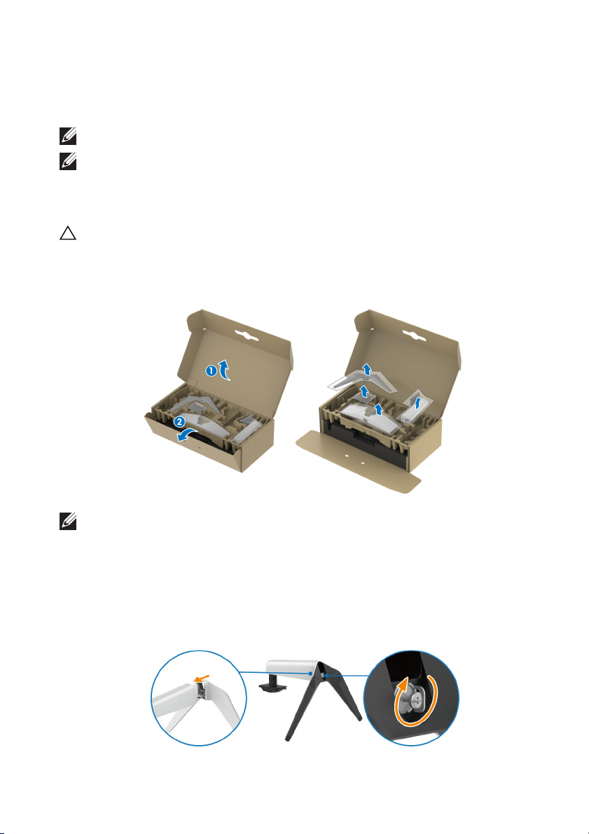
move the stand riser, stand base, I/O cover, and VESA adapter from the
1. Re
packaging cushion.
NOTE: The graphics are used for illustration purposes only. The
appearance of the package cushion may vary.
ign and place the stand riser on the stand base.
2. Al
3. Op
en the screw handle at the bottom of the stand base and turn it
clockwise to secure the stand assembly.
lose the screw handle.
4. C
to protect your curved
Setting up the monitor | 31
Page 32
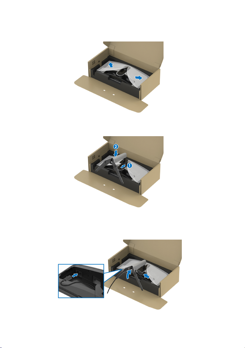
5. Open the protective cover on the monitor to access the VESA slot on the
display back cover.
6. C
arefully insert the tabs on the stand riser into the slots on the display back
cover and lower the stand assembly to snap it into place.
7. Route the power cable through the cable-management slot on the stand
and then through the cable-management clip behind the display.
onnect the power cable to the monitor.
8. C
32 | Setting up the monitor
Page 33
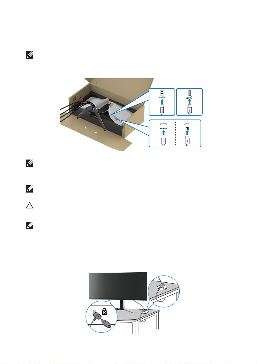
9. Rout
10.Connect
e the required cables through the cable-management slot on the
stand, such as HDMI cable, DisplayPort cable, USB 3.2 Gen 1 (5 Gbps)
pstream and downstream cables, and so on.
u
NOTE: The USB 3.2 Gen 1 (5 Gbps) cables are not shipped with your
display and sold separately.
the required cables to the monitor.
NOTE: Dell monitors are designed to work optimally with the Dellsupplied cables inside the box. Dell does not guarantee the video quality
and performance when using non-Dell cables.
NOTE: Route each cable neatly so that the cables are organized before
the I/O cover is attached.
CAUTION: Do not plug the power cable into the wall outlet or
monitor until you are instructed to do so.
NOTE: If you want to secure your monitor
lock, connect the Kensington lock cable to the security-lock slot at this
step. For more information about using the Kensington lock (sold
separately), see the documentation that is shipped with the lock. The
following image is for illustration purposes only. The appearance of the
lock may vary.
to a table using the Kensington
Setting up the monitor | 33
turn on the
Page 34
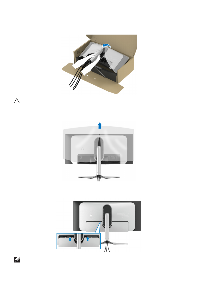
11. Hold the stand riser and lift the monitor carefully, then place it on a flat
surface.
CAUTION: Hold the stand riser firmly when lifting the monitor
any accidental damage.
12. Lift the protective cover from the monitor.
13. Slide
the tabs on the I/O cover into the slots on the display back cover until
it snaps into place.
to avoid
NOTE: Ensure that all cables pass through the I/O cover and cablemanagement slot on the stand riser.
34 | Setting up the monitor
Page 35
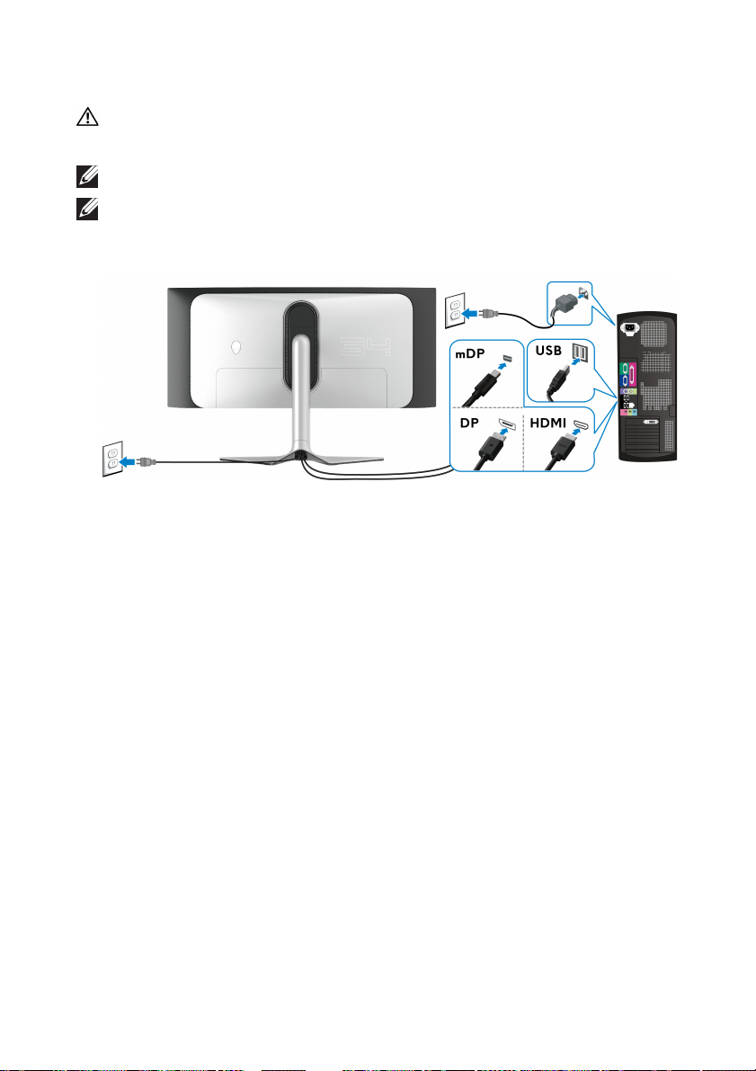
Connecting the computer
WARNING: Before you begin any of the procedures in this section,
follow the Safety instructions.
NOTE: Do not connect all cables to the computer at
NOTE: The images are for illustration purposes only. The appearance of
the computer may vary.
To connect your monitor to the computer:
1. Connect the other end of the DisplayPort cable (or Mini-DisplayPort to
DisplayPort) or HDMI cable to your computer.
2. Connect
appropriate USB 3.2 Gen 1 port on your computer.
onnect the USB peripherals to the SuperSpeed USB 5 Gbps (USB 3.2
3. C
Gen 1) downstream ports at the bottom of the monitor.
ug the power cables for your computer and monitor into a wall outlet.
4. Pl
5. Tur
If your monitor displays an image, installation is complete. If it does not
di
splay an image, see Common problems.
the other end of the USB 3.2 Gen 1 upstream cable to an
n on the monitor and the computer.
the same time.
Setting up the monitor | 35
Page 36
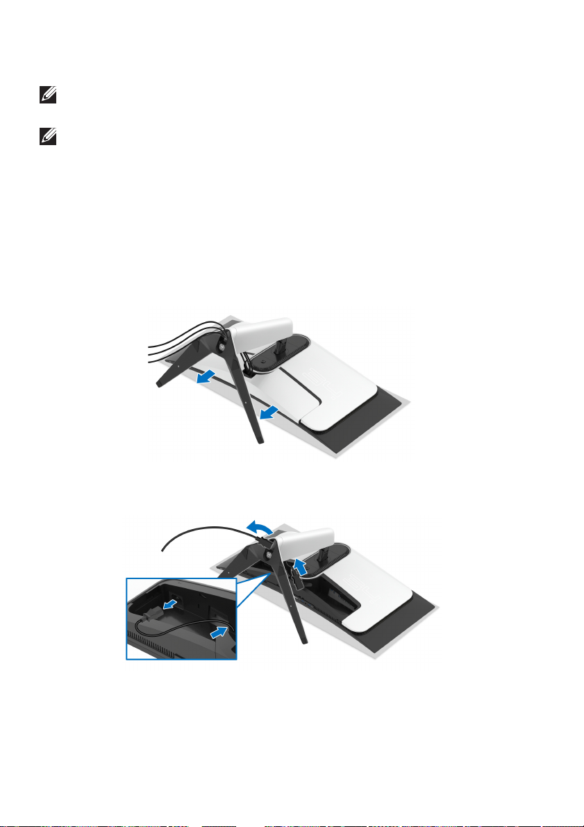
Removing the monitor stand
NOTE: To prevent scratches on the display when removing the stand,
ensure that the monitor is placed on a soft, clean surface.
NOTE: The following instructions are applicable only for removing the
stand that was shipped with your monitor. If you are removing a stand
that you purchased from any other source, follow the setup instructions
that were included with the stand.
To remove the stand:
n off the monitor.
1. Tur
2. Disconnect the cabl
3. Plac
e the monitor on a soft cloth or cushion.
4. C
arefully slide and remove the I/O cover from the monitor.
es from the computer.
5. Disconnect the cables from the monitor and slide them out through the
cable-management slot on the stand riser.
36 | Setting up the monitor
Page 37
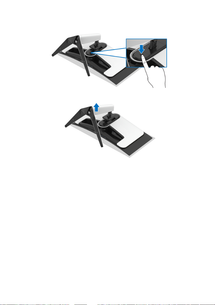
6. Press and hold the stand release button.
ft the stand up and away from the monitor.
7. Li
Setting up the monitor | 37
Page 38
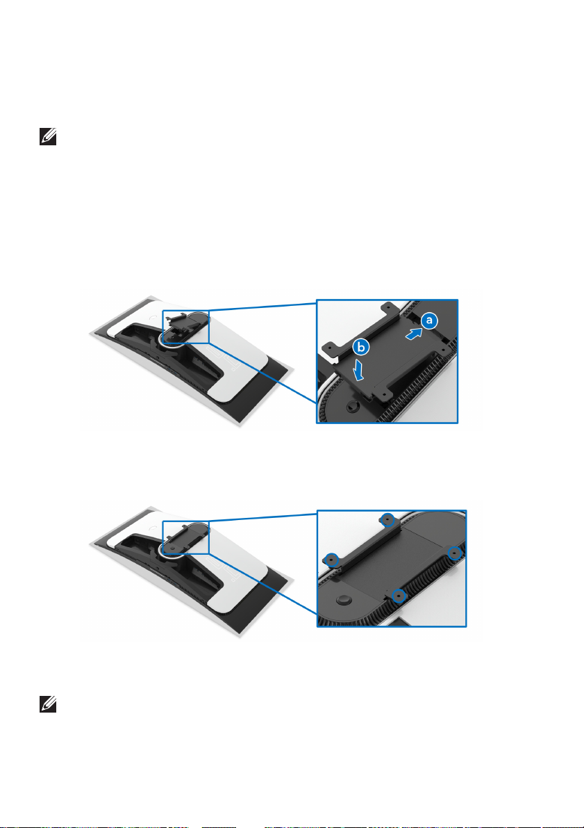
Attaching the VESA adapter (optional)
By installing the supplied VESA adapter onto the back of the display, you can
attach a wall-mount kit or 3rd-party arm (sold separately) to the monitor.
NOTE: The wall-mount kit or 3rd-party arm is not shipped with this
monitor.
e the monitor panel on a soft cloth or cushion on a stable flat surface.
1. Plac
2. Remove
3. At
a. Ins
b. Lowe
4. Using a Phillips crosshead screwdriver, tighten the wall mounting kit
(100 mm x 100 mm) to the VESA adapter with four screws (M4 x 10 mm,
hipped with the monitor).
s
the monitor stand. (See Removing the monitor stand.)
tach the supplied VESA adapter to the monitor.
ert the tabs on the VESA adapter into the slots on the display back
cover.
r the VESA adapter to snap it into place.
5. Mount the monitor on the wall by following the instructions that come with
the purchased wall-mount kit/3rd-party arm.
NOTE: For use only with UL-listed wall mount bracket with minimum
weight or load bearing capacity of 27.68 kg.
38 | Setting up the monitor
Page 39
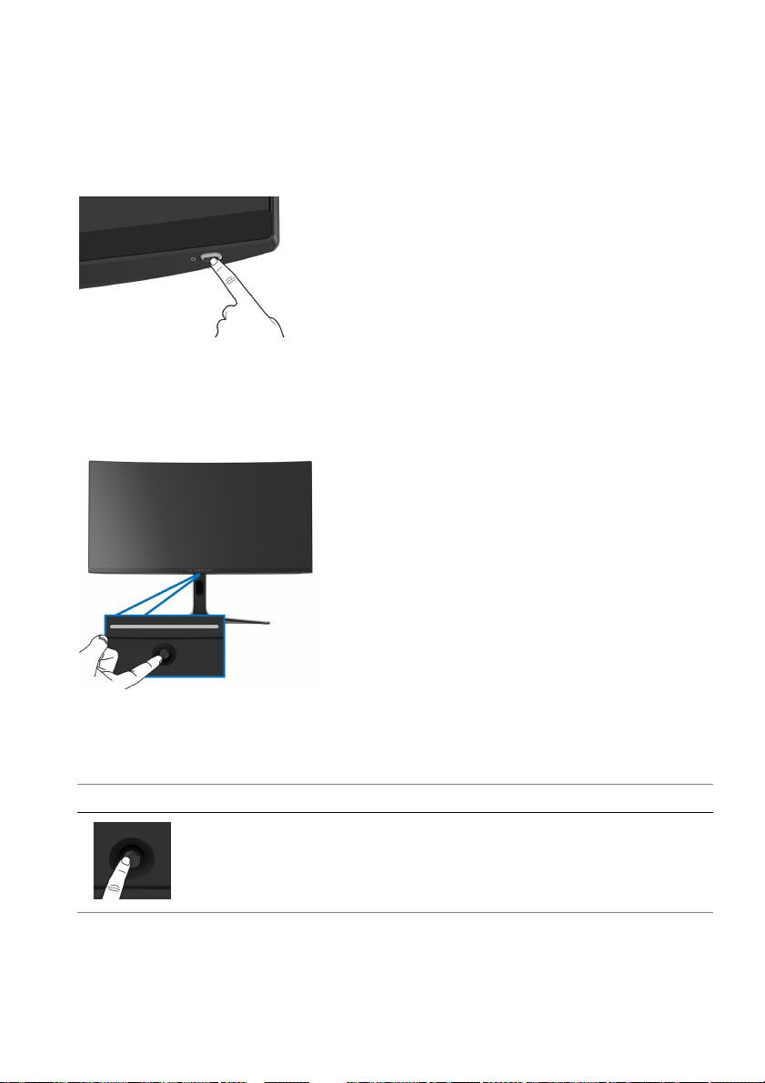
Operating the monitor
Turn on the monitor
Press the power button to turn on the monitor.
Using the joystick
Use the joystick at the bottom of the monitor to make On-Screen Display (OSD)
adjustments.
1. Press the joystick to launch the Menu Launcher.
2. Move
3. Press
Joystick Description
the joystick forward/backward/left/right to toggle through options.
the joystick again to confirm the settings and exit.
• When the OSD menu is on, press the joystick to confirm the
selection or save the settings.
• When the OSD menu is off, press the
Menu Launcher. See Accessing the Menu Launcher.
Operating the monitor | 39
joystick to launch the
Page 40
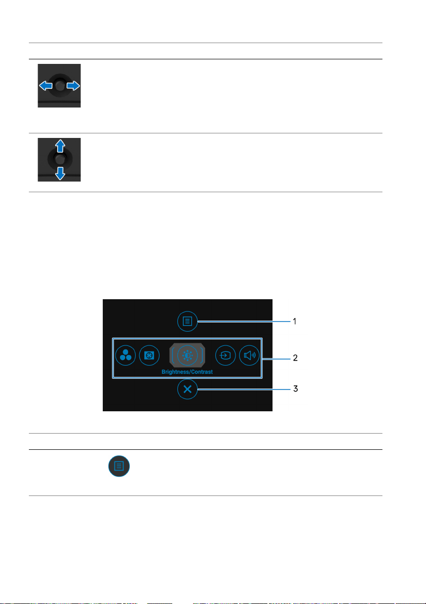
Joystick Description
• For 2-way (right and left) directional
• Move right to enter the submenu.
• Move left to exit from the current menu.
• Increases (right) or decreases (left) the parameters of selected
menu item.
• For 2-way (forward and backward) directional navigation.
• Toggles through the menu items.
• Increases (forward; away from you) or decreases
towards you) the parameters of selected menu item.
navigation.
(backward;
Using the On-Screen Display (OSD) menu
Accessing the Menu Launcher
When you move or press the joystick, the
center of the screen, allowing you to access the OSD menu and shortcut
functions.
To select a function, move the joystick.
Menu Launcher appears at the bottom
The following table describes the Menu Launcher functions:
Label Icon Description
1
Menu
40 | Operating the monitor
To launch the OSD main menu. See Accessing
the menu system.
Page 41
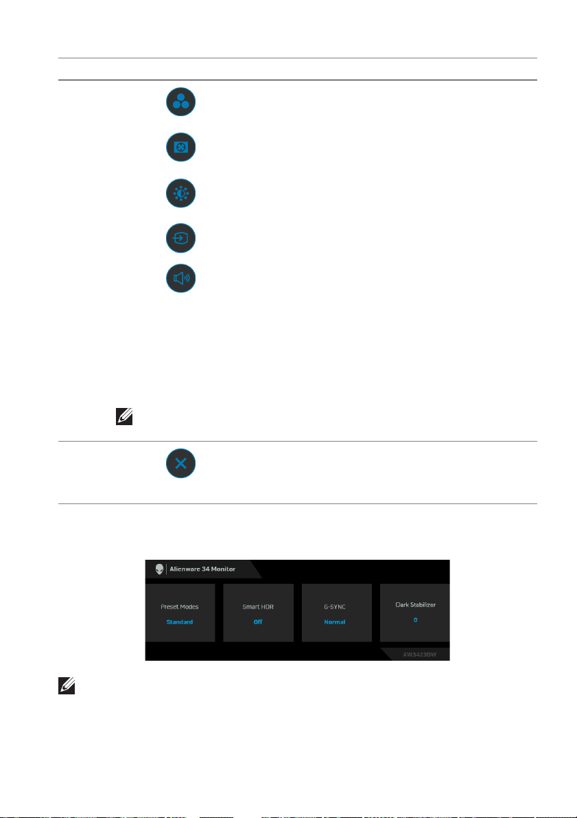
Label Icon Description
2
Shortcut functions
NOTE: You can set your preferred shortcut keys. See
Personalize for details.
3
When you move the joystick to the left or right
o toggle through the shortcut functions, the
t
selected item will be highlighted and shifted to
the center position. Press the joystick to enter
its submenu. After you change the settings by
moving the joystick, press the joystick to save
the changes before exiting.
• Preset Modes: To
mode from the list of preset modes.
rk Stabilizer: To access the Dark
• Da
Stabilizer adjustment slider.
• Brightness/Contrast:
adjustment sliders of brightness and contrast.
• Input Source:
from the list of video signals that may be
connected to your monitor.
• Volume:
slider.
To exit the Menu Launcher.
To access the Volume adjustment
choose a preferred color
To access the
To choose an input source
Exit
When you move or press the joystick, the
center of the screen, displaying the current settings of some OSD functions.
NOTE: The Smart HDR state is enabled automatically when your display
detects HDR content. It cannot be enabled manually.
OSD Status Bar appears at the top
Operating the monitor | 41
Page 42
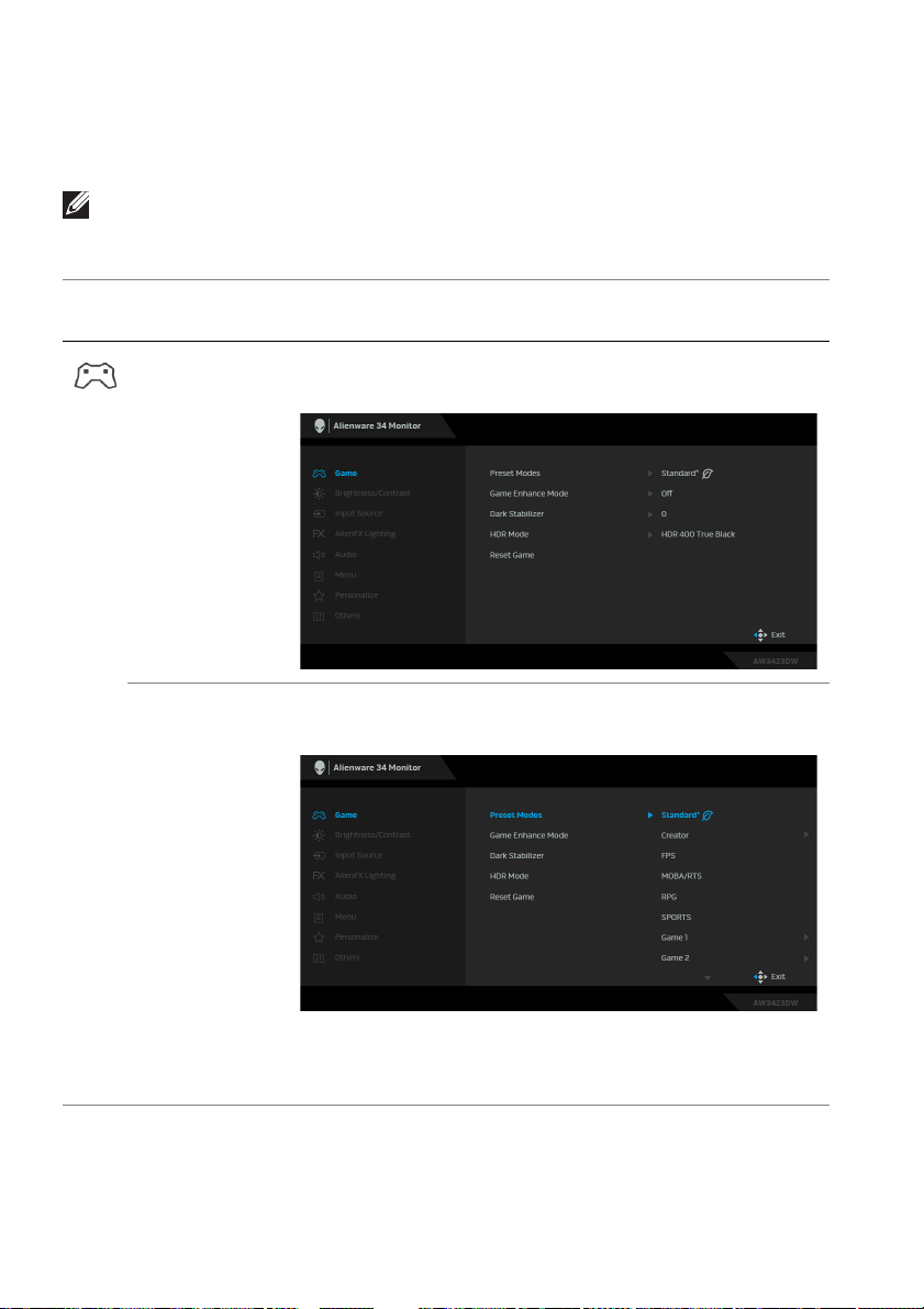
Accessing the menu system
After you change the settings, press the joystick to save the changes before
p
roceeding to another menu or exit the OSD menu.
NOTE: To exit the current menu item and return to the previous menu,
follow the direction icon displayed at the bottom-right corner of the OSD.
Icon Menu and
submenus
Game Use this menu to personalize your visual gameplay
Preset Modes Allows you to choose from the list of preset color
Description
experience.
modes.
• Standard*: Loads the monitor's default color
settings. This is the default preset mode. (* means
DisplayHDR-compliant)
42 | Operating the monitor
Page 43

Icon Menu and
menus
sub
Preset Modes • Cr
Description
eator: Allows you to set Color Space to DCI-P3
or sRGB and adjust the Gamma level (between 1.8
and 2.6). This mode is available only for SDR mode
and will be disabled when HDR is on.
S: Loads color settings ideal for First-Person
• FP
Shooter (FPS) games.
• MOBA/RTS: Loa
Multiplayer Online Battle Arena (MOBA) and RealTime Strategy (RTS) games.
• RPG: Loads
Games (RPG).
• SPORTS:
games.
• Game
customize the settings of color (R/G/B/C/M/Y)
and Dark Stabilizer for your gaming needs.
• Wa
The screen appears warmer with a red/yellow tint.
• Co
The screen appears cooler with a blue tint.
• Cu
color settings. Use the joystick to adjust the three
colors (R, G, B) values and create your own preset
color modes.
Loads color settings ideal for sports
1/Game 2/Game 3: Enables you to
rm: Presents colors at lower color temperatures.
ol: Presents colors at higher color temperatures.
stom Color: Enables you to manually adjust the
ds color settings ideal for
color settings ideal for Role-Playing
Operating the monitor | 43
Page 44
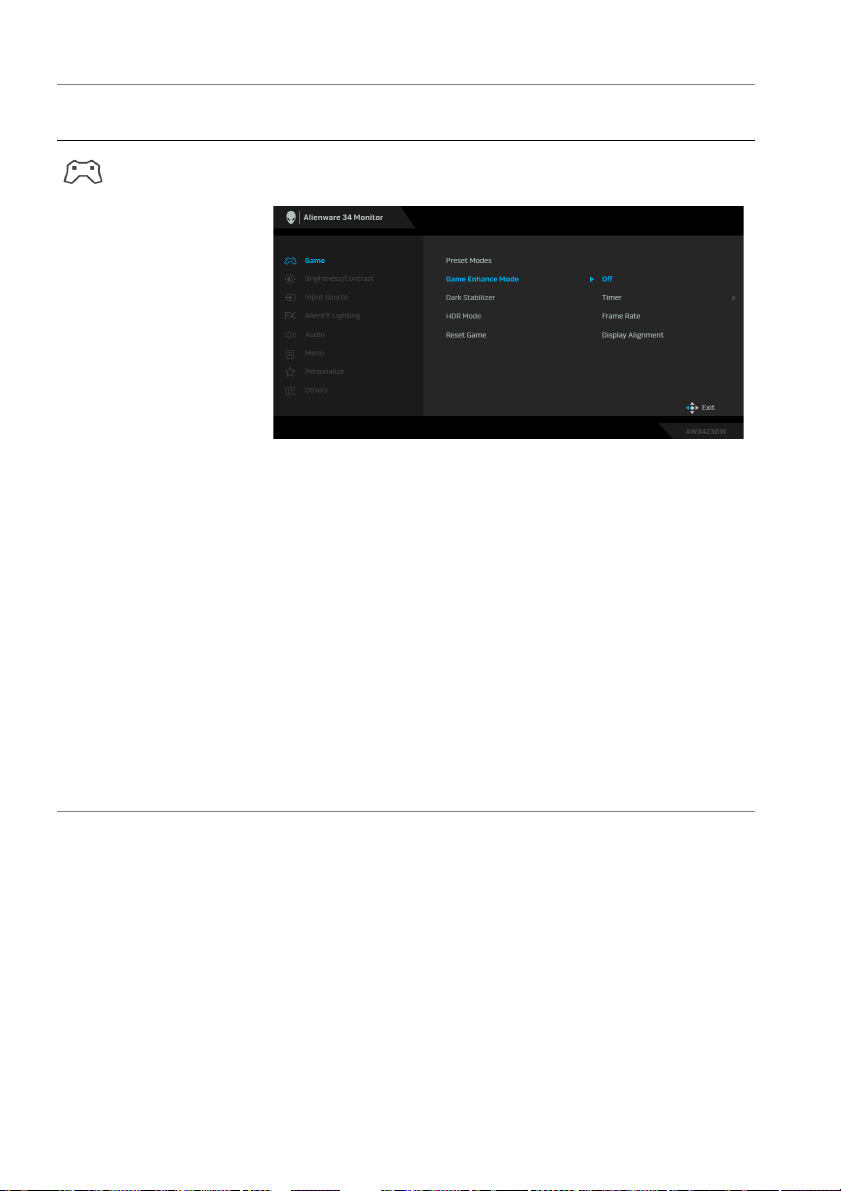
Icon Menu and
submenus
Game Enhance
Mode
Descriptio
The feature offers three available functions to enhance
your game
• Off: Select to disable the functions under Game
Enhance Mode.
• Timer:
the upper left corner of the display. The timer shows
the time elapsed since the game starts. Select an
option from the time-interval list to keep you aware
of the remaining time.
• Fr
second when playing games. The higher the rate, the
smoother the motion appears.
• Display Alignm
perfect alignment of the video contents from
multiple displays. Pressing the joystick again will exit
the Display Alignment mode.
play experience.
Allows you to disable or enable the timer at
ame Rate: Select to display the current frames per
ent: Select to help ensure the
n
44 | Operating the monitor
Page 45
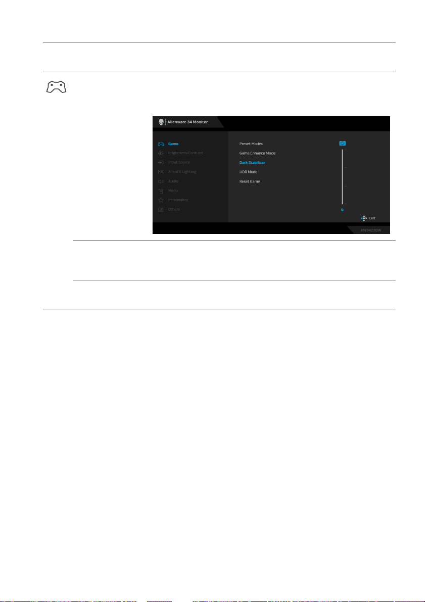
Icon Menu and
menus
sub
Dark Stabilizer The feature improves the visibility in the dark
scenarios. The higher the value (between 0 to 3), the
better visibility in dark area of the display image.
HDR Mode Allows you to set the HDR mode to HDR 400 True
Black or HDR Peak 1000. Press the joystick to confirm
the selection.
Reset Game Resets all settings under the Ga
defaults.
Description
gaming
me menu to the factory
Operating the monitor | 45
Page 46
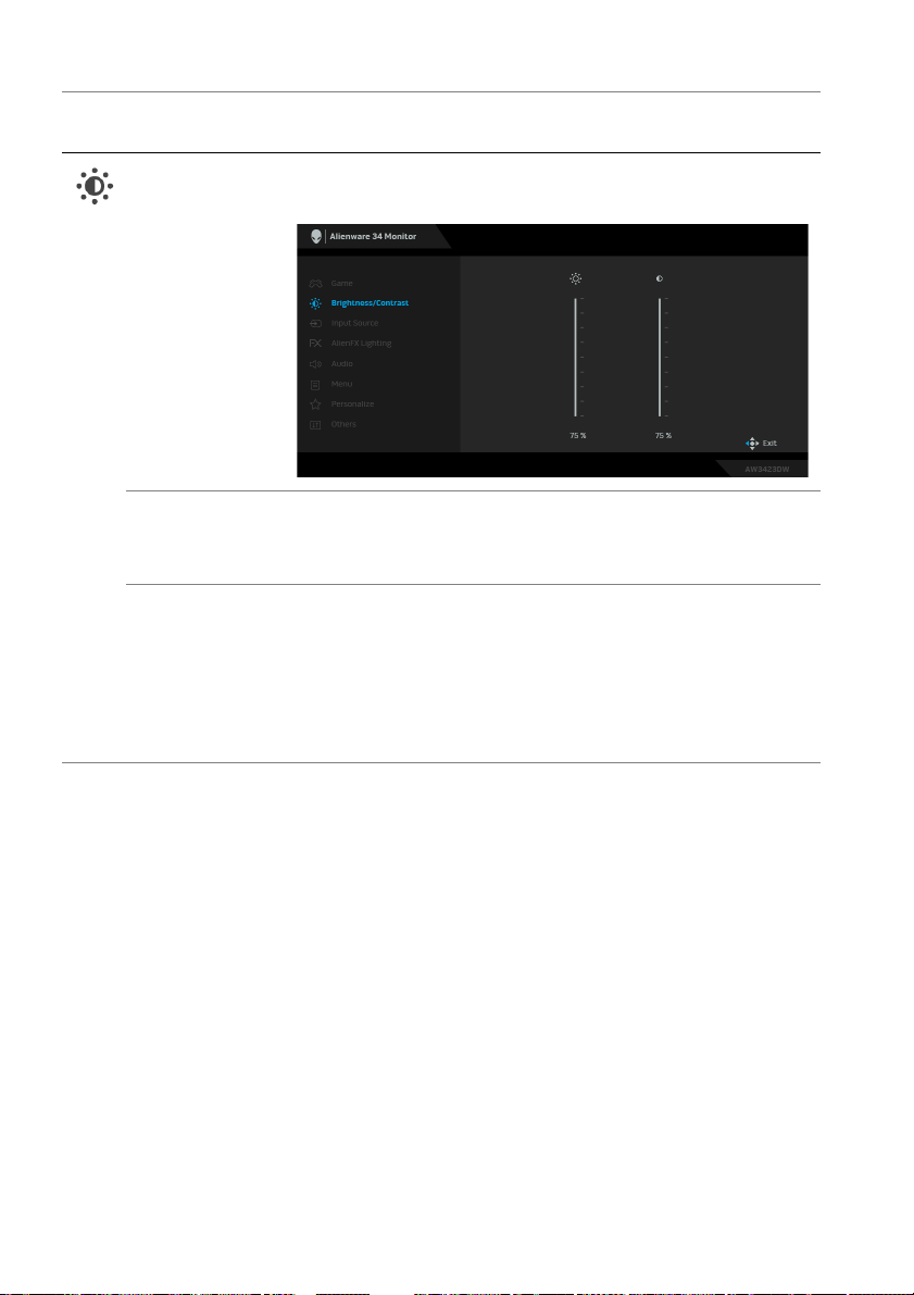
Icon Menu and
submenus
Brightness/
Contrast
Brightness Brightness adjusts the luminance of the backlight.
Contrast Adjust Brightness firs
Descriptio
Use this menu to activate Brightness/Contrast
adjustment.
Move the joystick to adjust the brightness level
(m
inimum 0/maximum 100).
t, and then adjust Contrast only if
further adjustment is necessary.
Move the joystick to adjust the c
0/maximum 100).
The Contrast feature
between darkness and lightness on the monitor screen.
adjusts the degree of difference
n
ontrast level (minimum
46 | Operating the monitor
Page 47
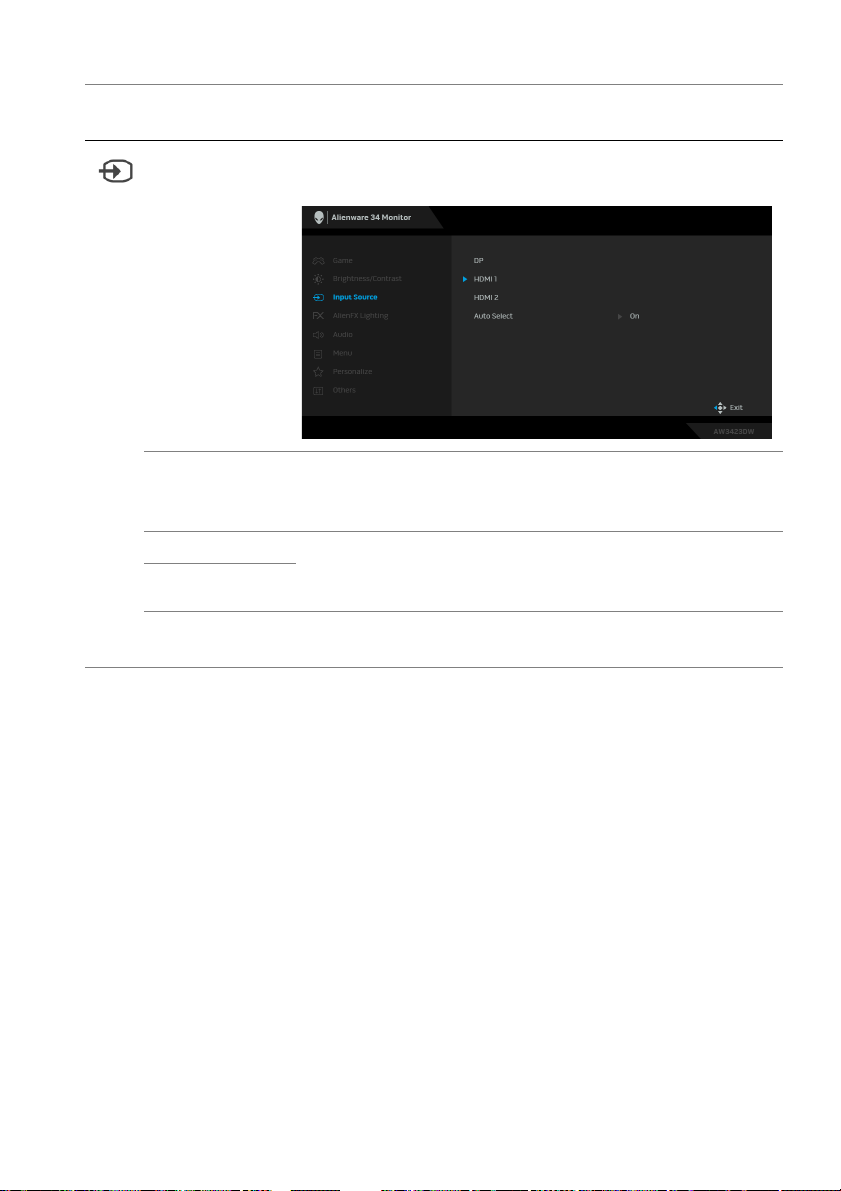
Icon Menu and
sub
menus
Input Source Use this menu to select between the different video
DP Select the DP input when you are using the
HDMI 1 Select the HDM
HDMI 2
Auto Select Automatically scans for avail
Description
gnals that may be connected to your monitor.
si
DisplayPort (DP) connector. Press the joystick to
confirm the selection.
I 1 or HDMI 2 input when you are
using the HDMI connector. Press the joystick to confirm
the selection.
able input sources. Press
the joystick to confirm the selection.
Operating the monitor | 47
Page 48
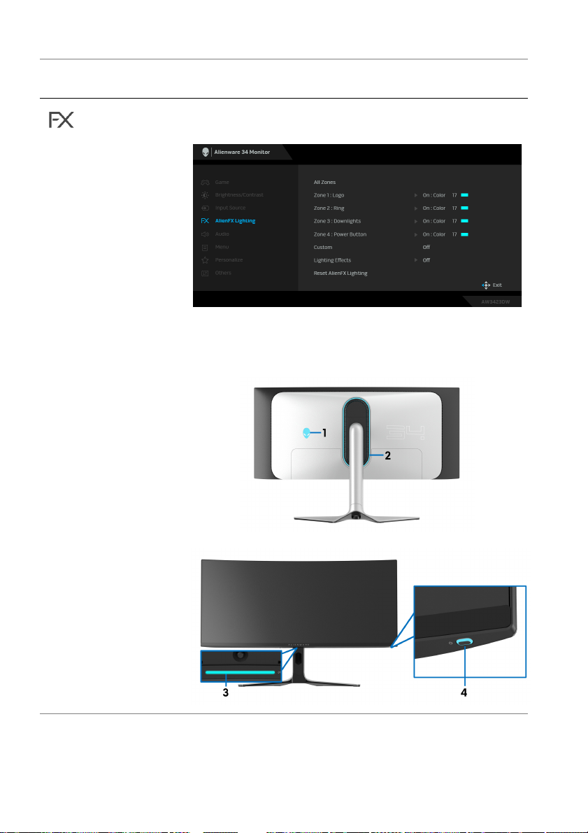
Icon Menu and
submenus
AlienFX
ghting
Li
Description
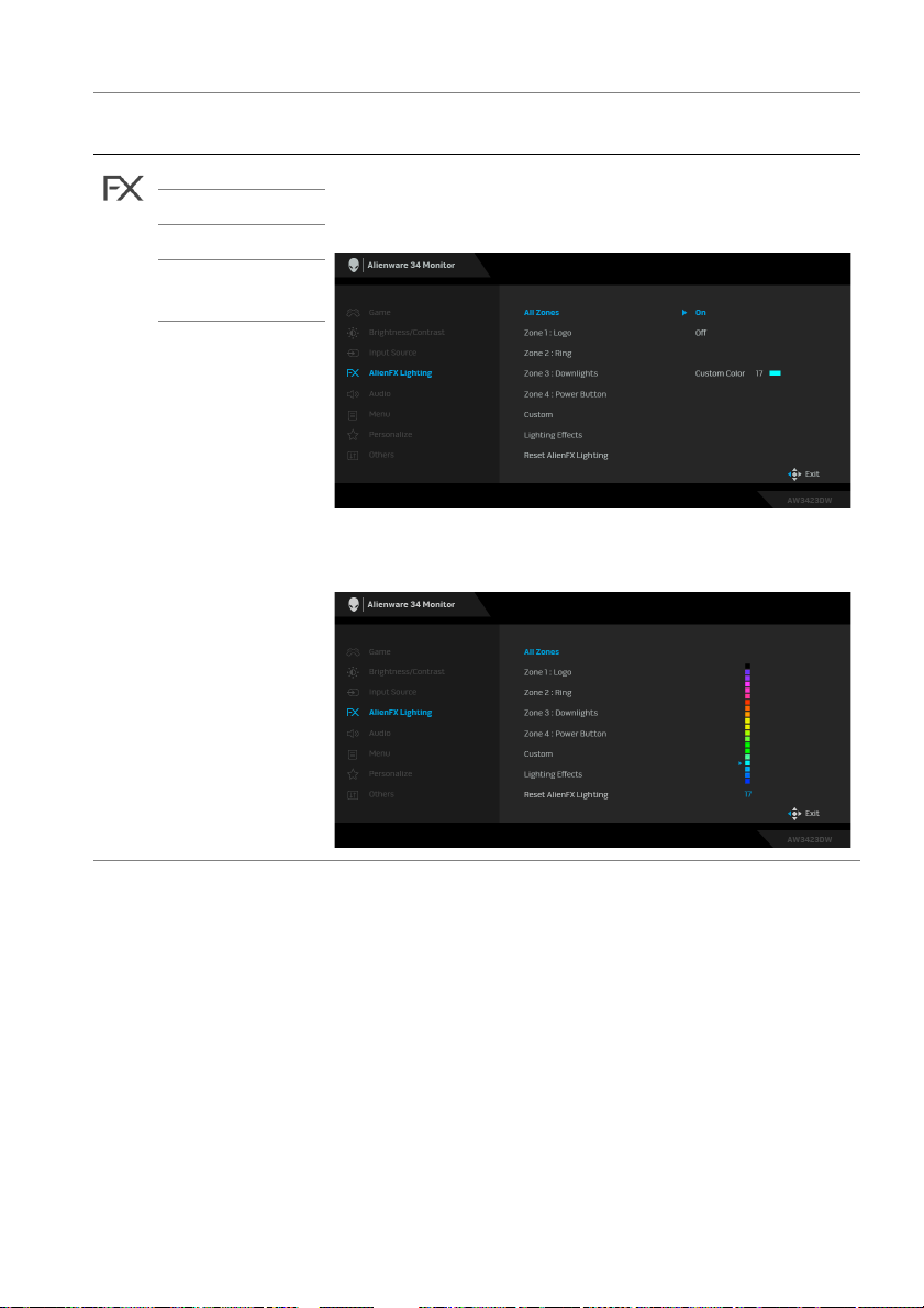
Adjusts the LED light settings for the Alienware logo,
ring strip, downlights, and Power button.
Before making any adjustments, select any or all of
these four zones from the submenus. The following
illustrations indicate the lighting zones.
48 | Operating the monitor
Page 49
Icon Menu and
sub
menus
All Zones To specify an LED lighting color for the selected zone,
Zone 1: Logo
Zone 2: Ring
Zone 3:
Downlights
Zone 4: Power
Bu
tton
Description
On, move the joystick to highlight Custom
select
Color, and press the joystick to enter its submenu.
Then move the joystick to make a selection from the list
of 20 available colors.
Operating the monitor | 49
Page 50
1 000
2 28 0 178
3 51 0 178
4 178 0 178
5 167 16 113
6 178 0 50
7 178 0 0
8 178 38 0
9 178 63 0
10 178 105 0
11 119 178 0
12 69 178 0
13 40 178 0
14 0 178 0
15 0 178 9
16 0 178 24
17 0 173 121
18 085165
19 0 43 178
20 0 0 178
No.
R
G
B
Icon Menu and
submenus
Descriptio
n
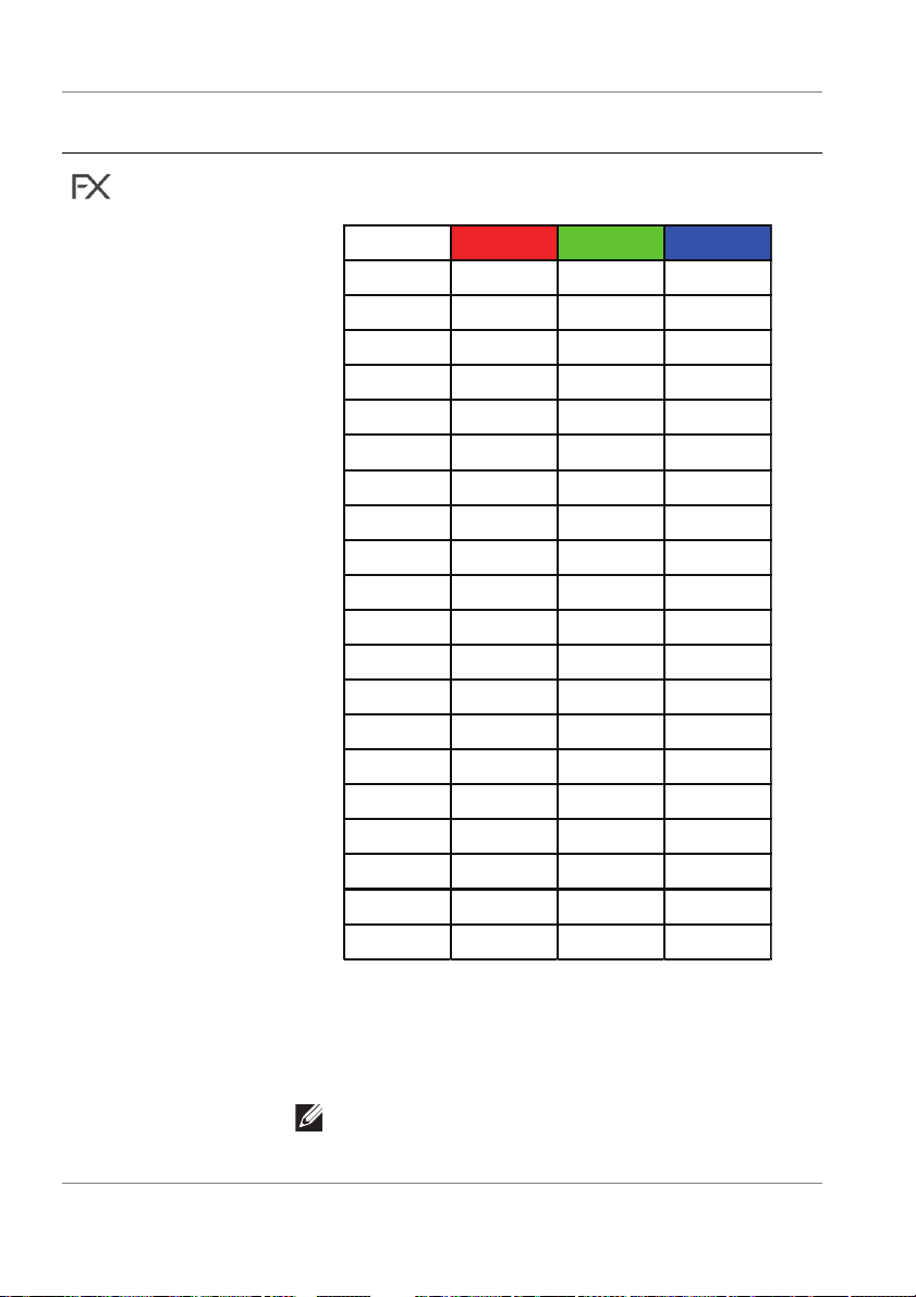
The following table depicts the color number and the
odes used for the 20 LED colors.
RGB c
50 | Operating the monitor
To turn off the light for All Zones/Zone 1/Zone 2/
Zone 3, se
lect Off.
For Zone 4, you may specif
the monitor is in on or standby mode.
NOTE: These functions are disabled when
Spectrum, Comet, or Rainbow Cycle (under
Lighting Effects) is activated.
y to turn off the light when
Page 51
Icon Menu and
menus
sub
Custom It is a read-only menu. When you use Custom Color
Lighting
Effects
Description
or/and Lighting Effects to
adjustments, this menu status shows Off; when you
make the LED lighting adjustments through AlienFX
application, the status shows On.
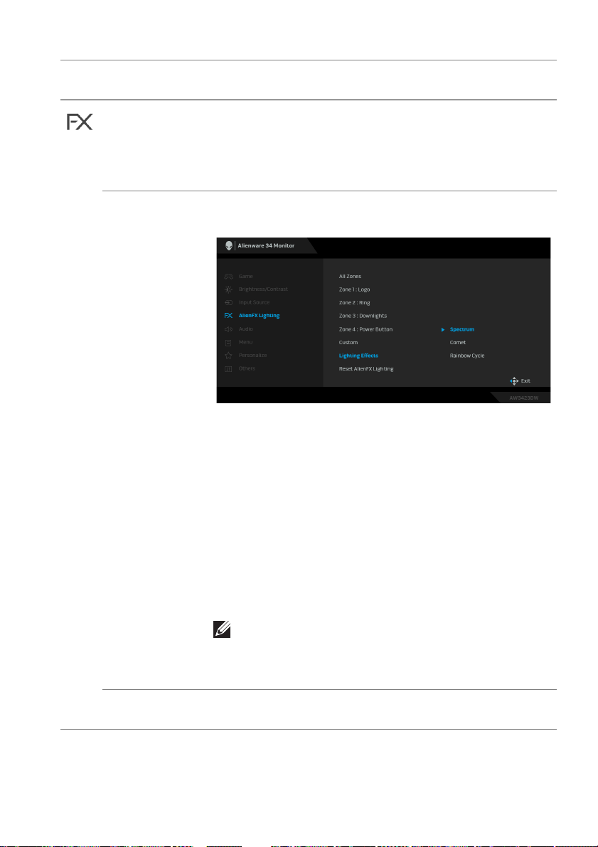
The default setting is Of
effect for the LED lights from the provided options.
• Spectrum: Select to make AlienFX lights of four
zones glow and change colors in the sequence of
the color spectrum: red, orange, yellow, green, blue,
indigo, and violet.
met: Select to let the LED lights glow like the
• Co
shimmering comet. Move the joystick to highlight
Custom Color, and press the joystick to enter its
submenu. Then move the joystick to make a selection
from the list of 20 available colors.
• Rainbow Cycle: Select
with the LED lights.
make LED lighting
f. You can choose a lighting
to deliver the rainbow effect
Reset AlienFX
hting
Lig
NOTE: When any of the above options is
selected, those functions under AlienFX Lighting
(except Reset AlienFX Lighting) will be turned
off.
Resets all settings under the AlienFX Lighting menu to
the factory defaults.
Operating the monitor | 51
Page 52
Icon Menu and
submenus
Audio
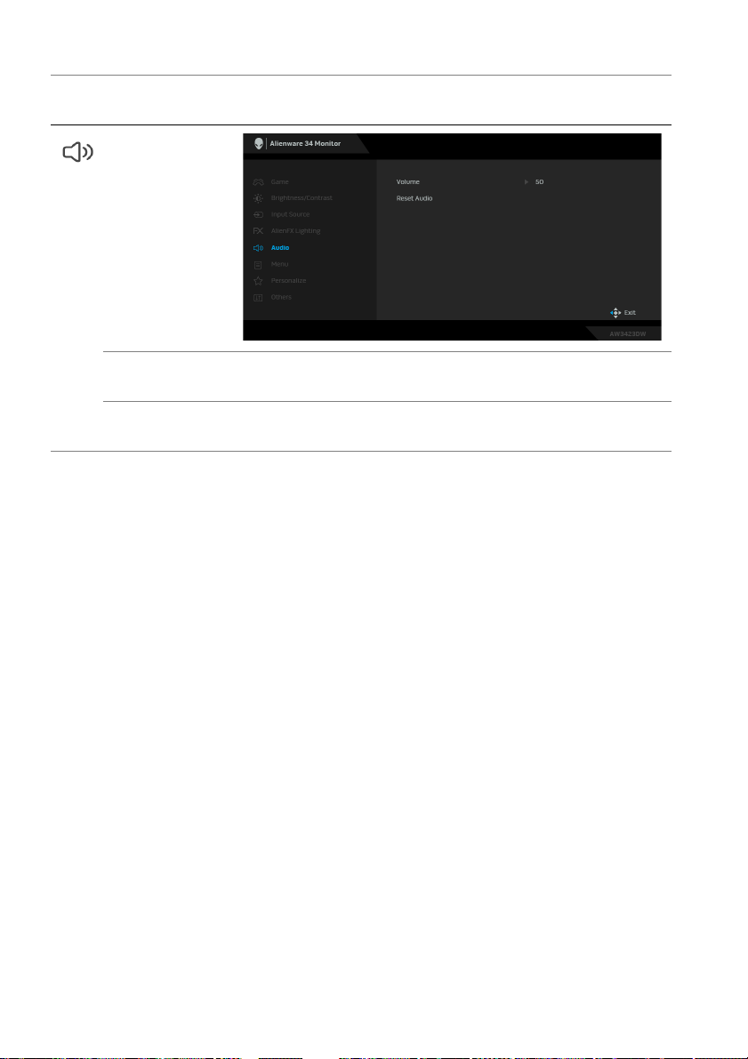
Volume Move the joystick to adjust the volume level of
Reset Audio Resets all settings under the Audio menu to
Descriptio
headphone output (minimum 0/maximum 100).
defaults.
n
the factory
52 | Operating the monitor
Page 53
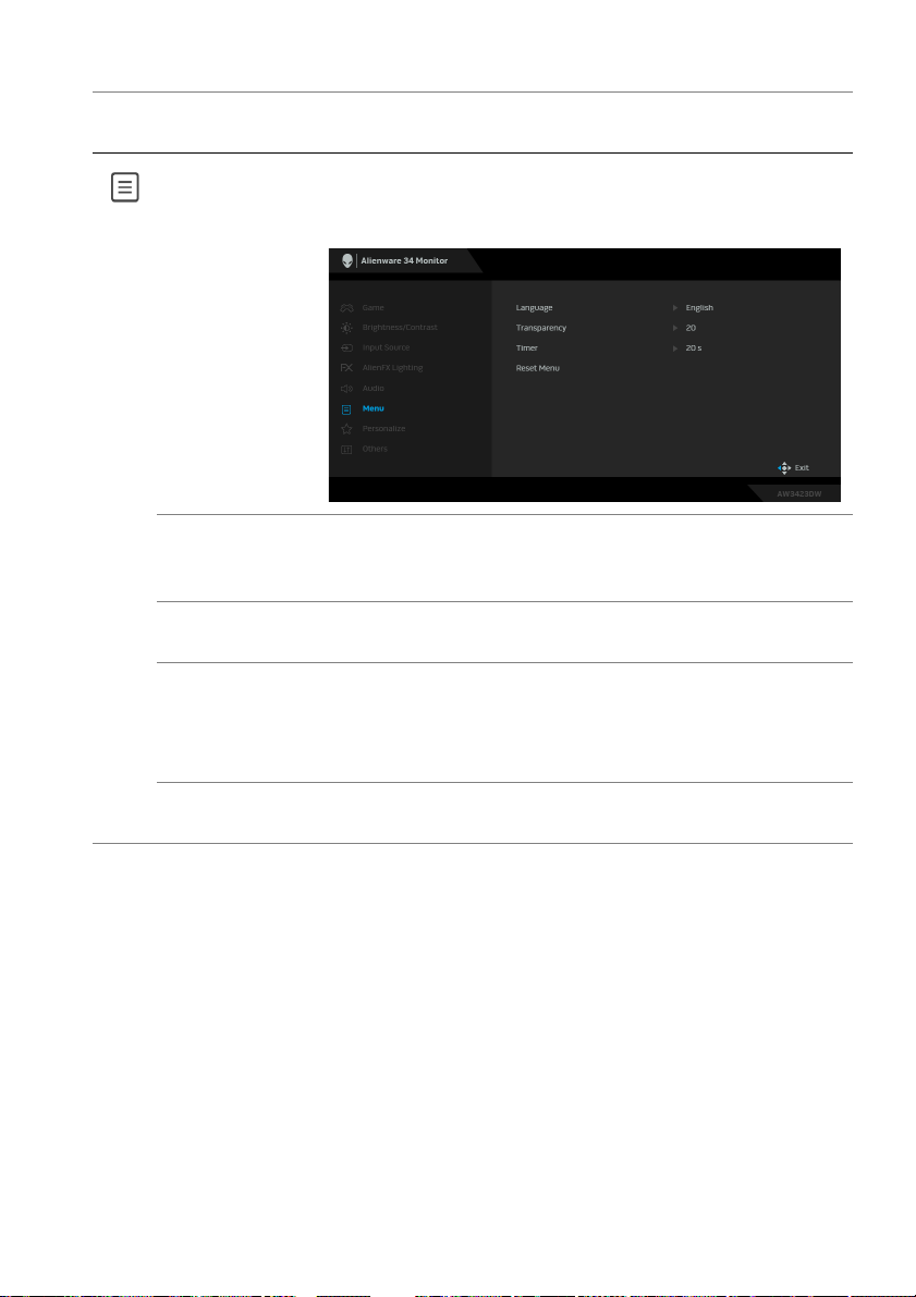
Icon Menu and
menus
sub
Menu Use this menu to adjust the settings of the OSD, such
Language Sets the OSD display to one of the eight languages:
Transparency Move the joystick to chang
Timer Sets the length of time for the OSD to remain active
Reset Menu Resets all settings under the Menu
Description
the languages of the OSD, the amount of time the
as,
menu remains on screen, and so on.
English, Spanish, French, German, Brazilian
Portuguese, Russian, Simplified Chinese, or Japanese.
e the menu transparency
(minimum 0/maximum 100).
after your la
Move the joystick to adjust the slider in 1 second
incremen
defaults.
st operation with the joystick.
t, from 5 to 60 seconds.
menu to the factory
Operating the monitor | 53
Page 54
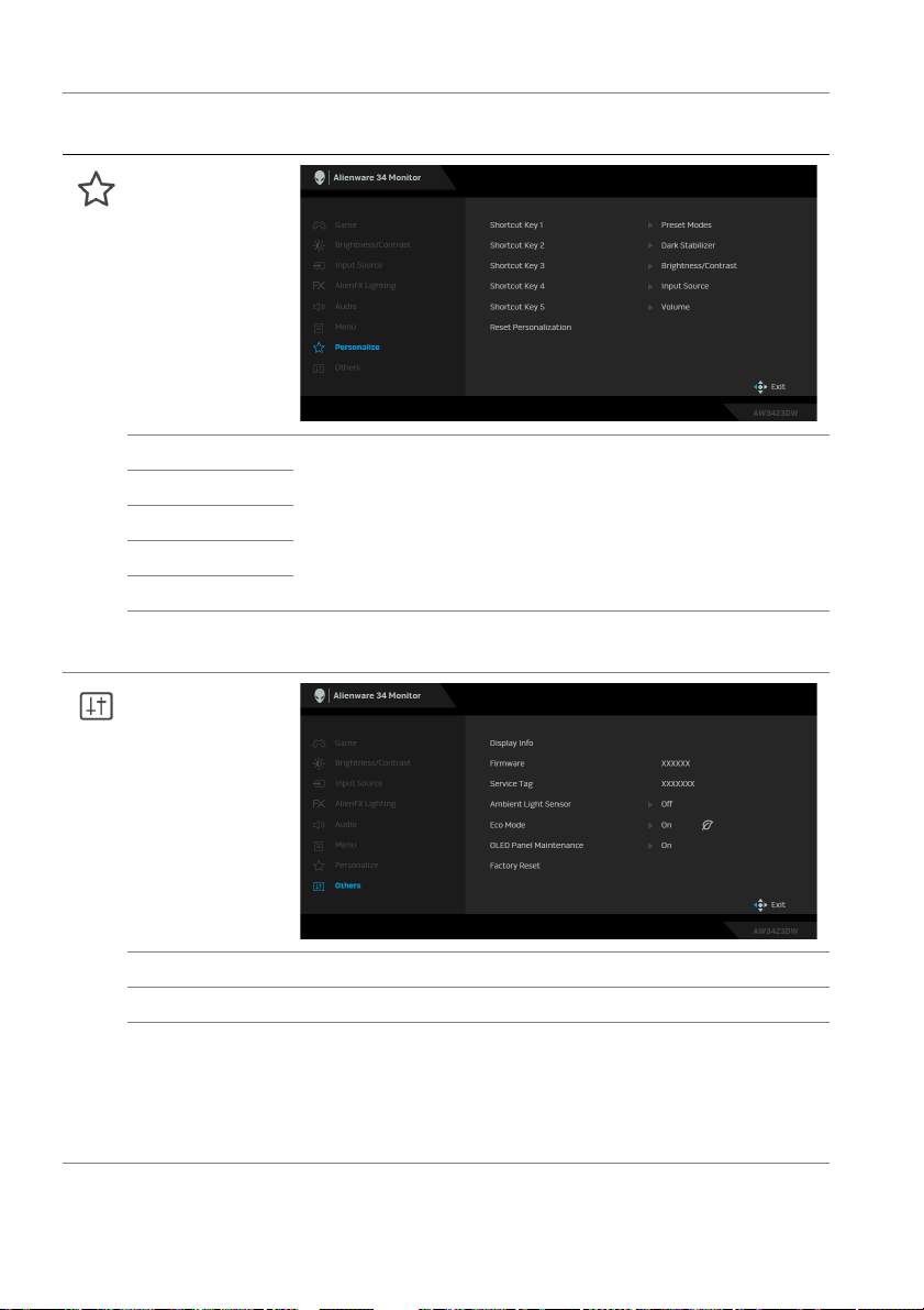
Icon Menu and
submenus
Personalize
Shortcut Key 1 Allows you to choose a feature from Preset Modes,
Shortcut Key 2
Shortcut Key 3
Shortcut Key 4
Shortcut Key 5
Reset
Personali
zation
Others
Game Enhance Mode, Dark Stabilizer, Brightness/
Contrast, Input Source, or Volume and set it as a
shortcut key. Press the joystick to confirm the selection.
Resets all settings under the Personalize menu to the
factory defaults.
Descriptio
n
Display Info Displays the monitor's current settings.
Firmware Displays the firmware version of your monitor.
Service Tag Displays the Service Tag of your monitor. The Service
T
ag is a unique alphanumeric identifier that is required
when you contact Dell technical support, access
warranty information, search for latest drivers on Dell
support website and so on.
54 | Operating the monitor
Page 55
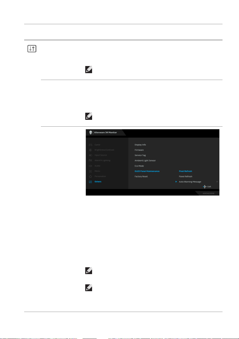
Icon Menu and
menus
sub
Ambient Light
Sensor
Eco Mode When the computer goes into standby mode, the Eco
OLED Panel
Maintenance
Description
When you set it to On, t
adjusts the brightness of the display based on ambient
light conditions. The default setting is Off.
NOTE: When HDR content is displayed, this
option is disabled.
Mode
enables the monitor to go into Standby mode as
well. The default setting is On. Selecting Off may
prevent the monitor from going into Standby mode.
NOTE: Pressing the joystick may wake up the
monitor after it goes into Standby mode.
he monitor automatically
The feature prevents the screen from image retention
by offering these functions:
• Pixe
l Refresh: To reduce temporary image retention
on the screen, you can manually activate this function
after using the monitor for a couple of hours.
Alternatively, the function will be activated
automatically when you have used the monitor for 4
hours/20 hours. The process takes approximately 6
to 8 minutes to complete.
NOTE: The power LED indicator blinks slowly in
green during the refresh process.
NOTE: If the accumulated usage time exceeds 4
hours, Pixel Refresh will be activated
automatically when the monitor goes into
Standby mode.
Operating the monitor | 55
Page 56
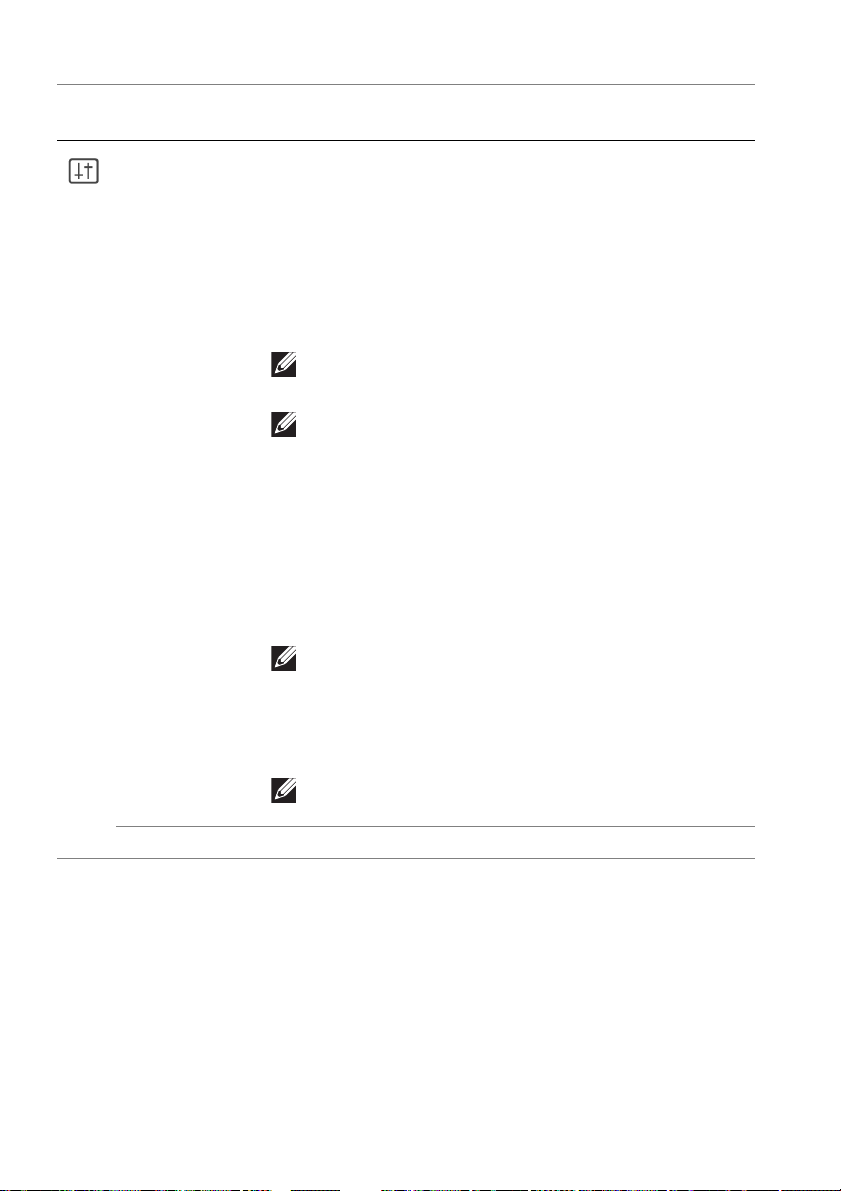
Icon Menu and
submenus
OLED Panel
Maintenance
Descriptio
• Panel Refr
retention caused by static content when you use the
monitor for 1500 hours, you can manually activate
this function to refresh the pixels. Alternatively, the
function will be activated automatically when the
accumulated usage time exceeds the factory default
setting (1500 hours). The process takes
approximately an hour to complete.
NOTE: The power LED indicator blinks slowly in
red during the refresh process.
NOTE: To obtain a better performance of Panel
Refresh, activate the function within a
temperature range of 0°C to 45°C.
• Auto W
the warning messages as reminders whenever the
accumulated usage time exceeds the factory default
settings. The default setting is On. If you select Off,
the warning message will not appear, yet the
calculation of accumulated usage hours continues.
NOTE: If Auto Warning Message is set to Off
and the accumulated usage time exceeds 4 hours,
Pixel Refresh will be activated automatically
when you press the power button of the monitor
or the monitor goes into Standby mode.
esh: To prevent permanent image
arning Message: To automatically provide
n
NOTE: This option is available only in the latest
firmware version (A01).
Factory Reset Resets all OSD settings to the factory defaults.
56 | Operating the monitor
Page 57
OSD warning message
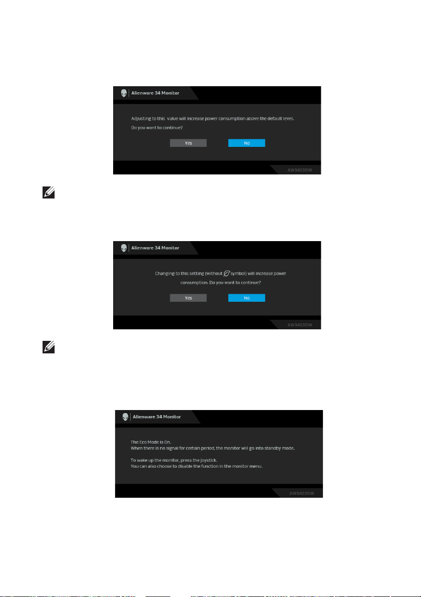
When you adjust the Brightn
the following message appears:
NOTE: If you select Yes, the message will not appear the next time you
changes the Brightness setting.
When you change the default setting of pow
such as Eco Mode or Preset Modes, the following message appears:
ess level above the default level for the first time,
er saving features for the first time,
NOTE: If you select Yes for either of the features mentioned above, the
message will not appear the next time you change the settings of these
features. When you perform a factory reset, the message will appear
again.
When the monitor goes into Standby mode, the
When Eco Mode is On
following message appears:
Operating the monitor | 57
Page 58
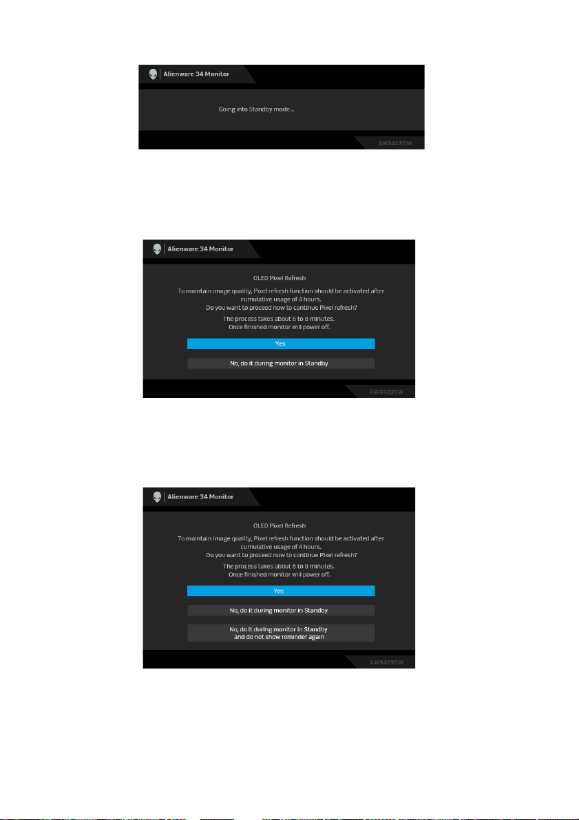
When Eco Mode is Off
Activate the computer and wake up the
When Pi
Once you select Yes, the monitor will be turned off and the refresh process will
run automatically. The process takes approximately 6 to 8 minutes to complete.
When the monitor is turned on after four hours of cumulative usage, the Pix
Refresh function runs automatically and notifies you with the following message:
xel Refresh is selected, the following message appears:
monitor to gain access to the OSD.
el
Select Yes, and the refresh process will run automatically after the monitor is
turned off. The process takes approximately 6 to 8 minutes to complete.
58 | Operating the monitor
Page 59
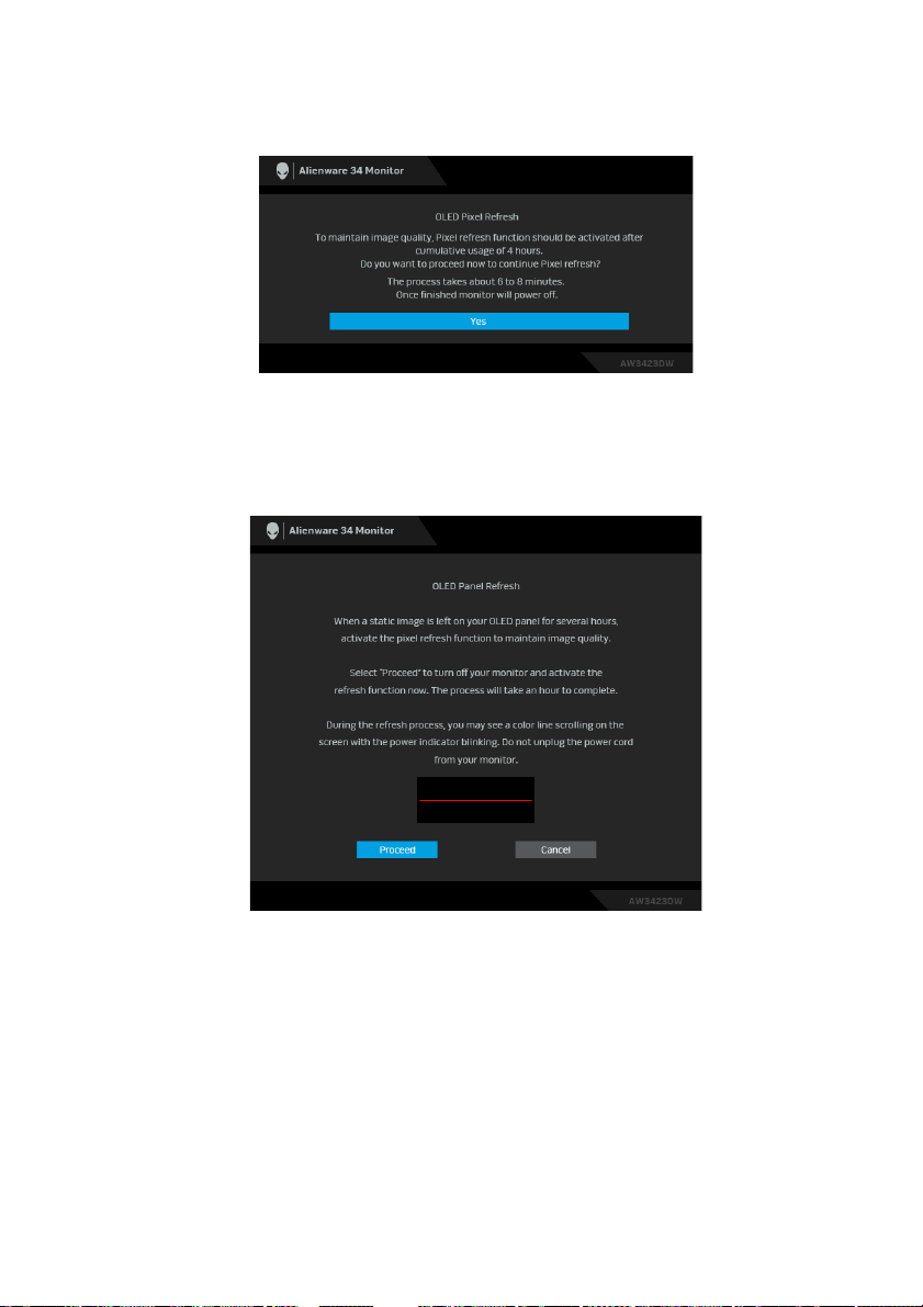
When the monitor is turned on after twenty hours of cumulative usage, the Pi
Refresh function runs automatically and notifies you with the following message:
Select Yes, and the refresh process will run automatically after the monitor is
turned off. The process takes approximately 6 to 8 minutes to complete.
When Panel Ref
more than 1500 hours, the following message appears:
resh is selected or the cumulative usage time of the monitor is
xel
Select Proceed, and the refresh process will run automatically. The process takes
approximately an hour to complete.
Operating the monitor | 59
Page 60
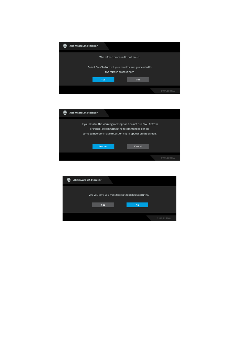
If you press the power button during the process of running Pix
Panel Refresh, the following message appears:
When you set Auto Warning Message to Off, the following message appears:
When Factory Reset is selected, the following message appears:
el Refresh or
See Troubleshooting for more information.
60 | Operating the monitor
Page 61

Setting the maximum resolution
NOTE: The steps may vary slightly depending on the version of Windows
you have.
To set the maximum resolution for the monitor:
In Windows 8.1:
1. For Windows 8.1, select the Desktop tile to switch to classic desktop.
2. Right-click on the desktop and click Screen resolution.
3. If you have more than one monitor connected, ensure that you select
AW3423DW.
4. Click the Screen Resolution dropdown list and select 3440 x 1440.
5. Click OK.
In Windows 10 and Windows 11:
1. Right-click on the desktop and click Display settings.
2. If you have more than one monitor connected, ensure to select
AW3423DW.
3. Click the Display Resolution dropdown list and select 3440 x 1440.
4. Click Keep changes.
If you do not see 3440 x 1440 as an option, you must update your graphics
driver to the latest version. Depending on your computer, complete one of the
following procedures:
If you have a Dell desktop or a laptop:
•Go to https://www.dell.com/support, enter your service tag, and
download the latest driver for your graphics card.
If you are using a non-Dell computer (laptop or desktop):
• Go to the support site for your computer and download the latest graphic
drivers.
• Go to your graphics card website and download the latest graphic drivers.
Operating the monitor | 61
Page 62
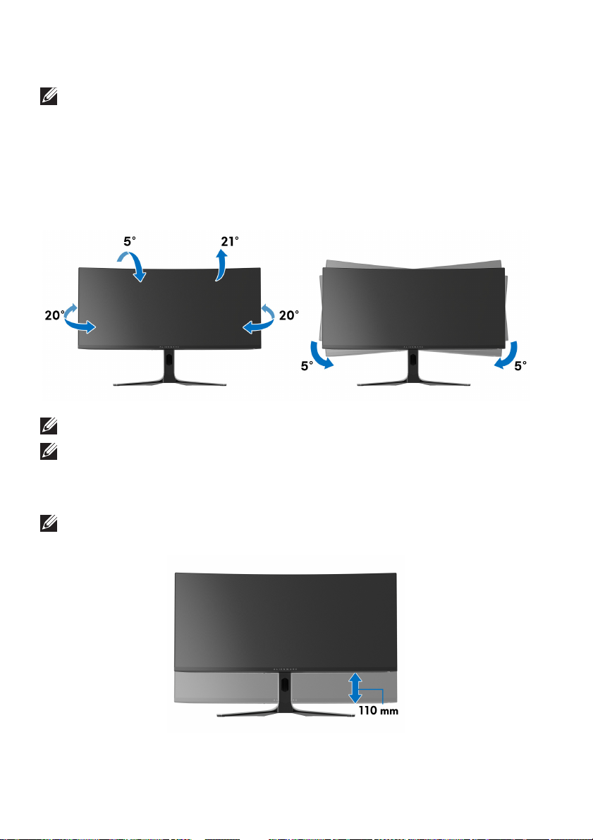
Using the tilt, swivel, and vertical extension
NOTE: The following instructions are applicable only for attaching the
stand that was shipped with your monitor. If you are attaching a stand
that you purchased from any other source, follow the setup instructions
that were included with the stand.
Tilt and swivel extensions
With the stand attached to the monitor, you can tilt and swivel the monitor for
he most comfortable viewing angle.
t
NOTE: The stand is not factory-installed.
NOTE: The slant angle of this monitor is between -5° and +5°, not
allowing for pivot movements.
Vertical extension
NOTE: The stand extends vertically up to 110 mm. The following figure
illustrates how to extend the stand vertically.
62 | Operating the monitor
Page 63

Using AlienFX application
You can configure the LED lighting effects across multiple distinct zones on your
Alienware monitor through AlienFX in Alienware Command Center (AWCC).
NOTE: If you have an Alienware Gaming Desktop or Laptop, you can
directly access AWCC to control the lightings.
NOTE: For more information, see Alienware Command Center Online
Help.
Prerequisites
Before installing the AWCC on a non-Alienware system:
• Ensure that the OS of your computer is Windows 10 R3 or later.
• Ensure your Internet connection is active.
• Ensure that the supplied USB 3.2 Gen 1 (5 Gbps) upstream cable is
connected to both the Alienware monitor and the computer.
Installing AWCC through Windows update
1. The AWCC application is downloaded and will be automatically installed.
The installation takes a few minutes to complete.
2. Navigate to the program folder to ensure that the installation is successful.
Alternatively, you can find the AWCC application in the Start menu.
3. Launch AWCC and perform the following steps to download the additional
software components:
•In the Settings window, click Windows Update, and then click Check
for updates to check the Alienware driver update progress.
• If the driver update is not responding in your computer, install AWCC
from the Dell Support website.
Installing AWCC from the Dell Support website
1. Enter AW3423DW in the query field at www.dell.com/support/drivers,
and download the latest version of the following items:
• Alienware Command Center Application
• Alienware Gaming Monitor Communication Driver
2. Navigate to the folder in which you saved the setup files.
3. Double-click the setup file and follow the on-screen instructions to
complete the installation.
Using AlienFX application | 63
Page 64
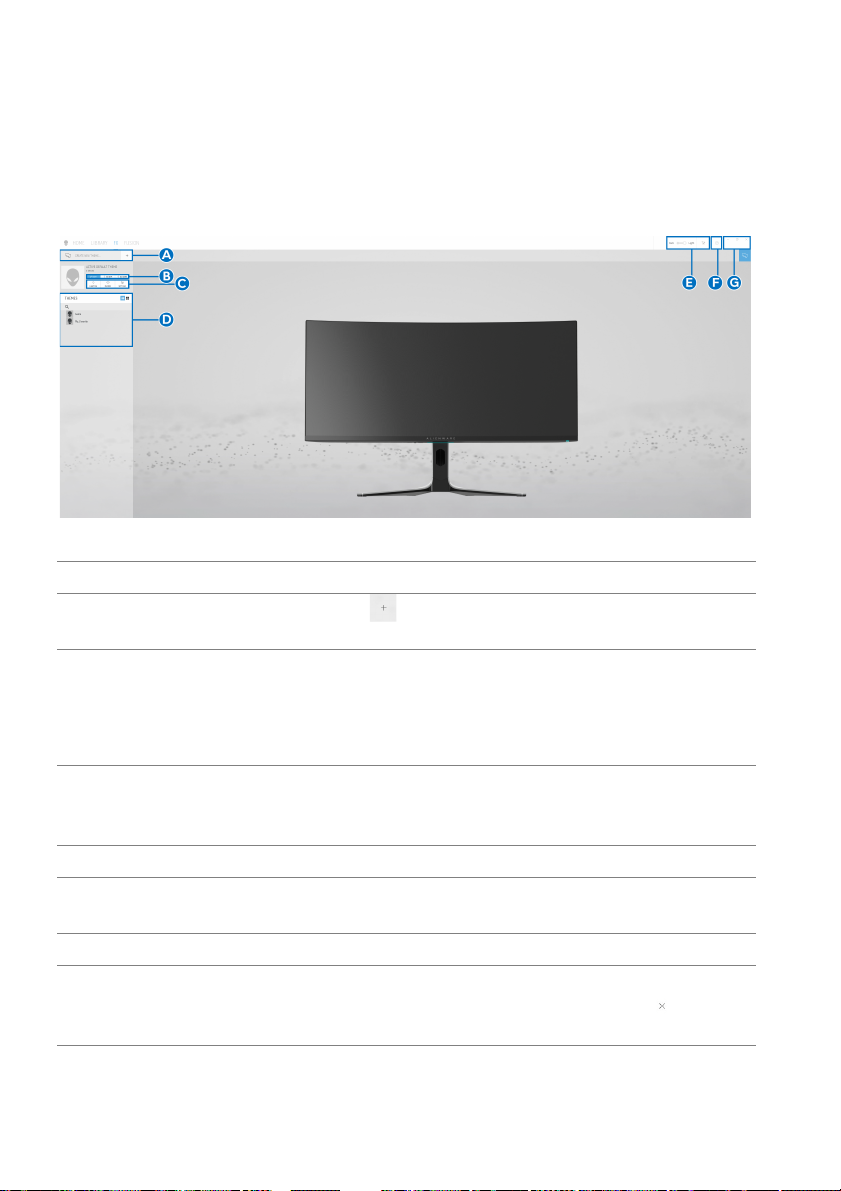
Navigating the AlienFX window
With the Alienware Command Center, AlienFX enables you to control the LED
lighting colors and transition effects for your Alienware monitor.
In the AWCC home screen, click FX in the
screen of AlienFX.
The following table describes the functions and features on the home screen:
Callout Function Description
A CREATE NEW
THEME...
B Edit controls • EDIT: Provides options
C Theme components You can use these components (LIGHTING,
D THEMES li
E Background
controls
F Help Click to access the AWCC Online Help.
G Window controls You can use the buttons to minimize, maximize, or
st Displays the themes in list view or grid view.
Click
add a theme.
lighting settings for your theme.
• GO DI
• GO DA
MACROS, SETTINGS) t
theme as an active theme.
Adjusts the background animation effects.
restore the size
selected, the application will close.
top menu bar to access the home
and then enter a name in the text box to
for you to customize
M: Makes the light dimmer.
RK: Turns off the light.
o make the selected
of the window. When
is
64 | Using AlienFX application
Page 65
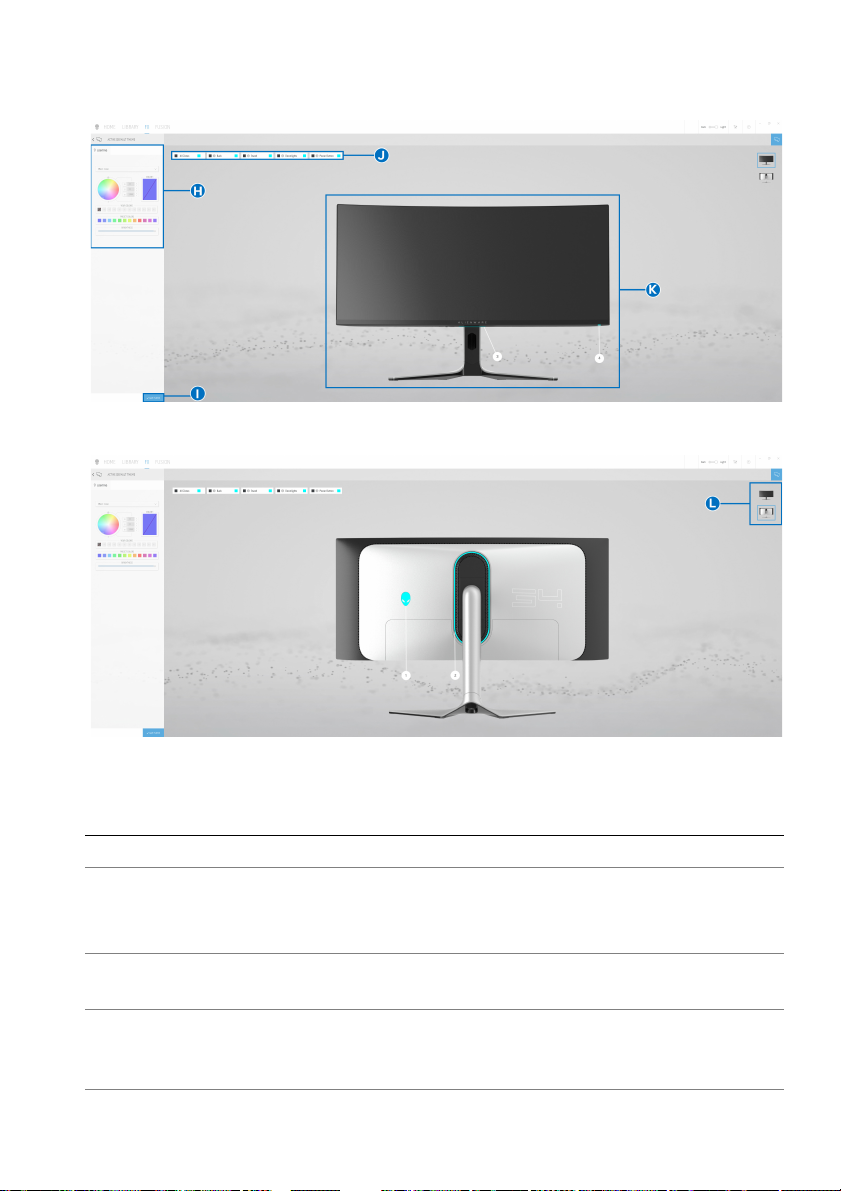
When you start to customize a theme, you should
Screen with the front view of monitor
see the following screen:
Screen with the back view of monitor
The following table describes the function
Callout Function Description
H LIGHTING pane
I SAVE THEME Click to save all adjustments and changes for the
J Zone selection To make adjustments for a single zone, click the
l Use the controls in this panel to set up lighting
effects for a theme.
See Setting lighting effects for details.
theme.
s
pecific check box. To make adjustments for all
zones, select the All Zones check box.
s and features on the screen:
Using AlienFX application | 65
Page 66
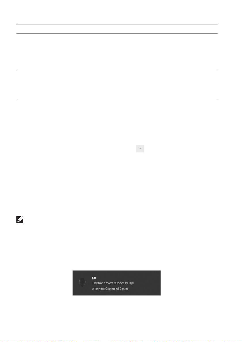
Callout Function Description
K Live preview The lighting zones are with numbered callouts.
You may select a single zone by clicking the
number on the image. When you make lighting
adjustments, the preview of the monitor displays
the new effects simultaneously.
L Thumbnails Displays the thumbnails of the Alienware monitors
cted to your computer. The image
conne
displayed in the live preview area is selected from
this thumbnail list.
Creating a theme
To create a theme with your preferred lighting settings:
1. Launch AW
2. Cl
ick FX in the top menu bar to access the home screen of AlienFX.
CC.
3. In the top-left
4. In the
5. Sp
6. In the LIGHTING p
NOTE: Some effects are available for All Zones only, such as Spectrum,
Static Default Blue, Rainbow Cycle, Blink, Comet, Breathing RGB, and
Racing.
7. Repeat step 5 and step 6 to make more configuration options available to
8. Wh
CREATE NEW THEME text box, type the theme name.
ecify the lighting zone(s) for which you want to make lighting
adjustments by:
• selecting the zone check box(es) above the live preview area, or
clicking the numbered callout on the image of monitor
•
drop-down list. See Setting lighting effects for details.
your preference.
en done, click SAVE THEME. A toast notification appears in the right-
bottom corner of the screen.
corner of the window, click to create a new theme.
anel, select your preferred lighting effects from the
66 | Using AlienFX application
Page 67
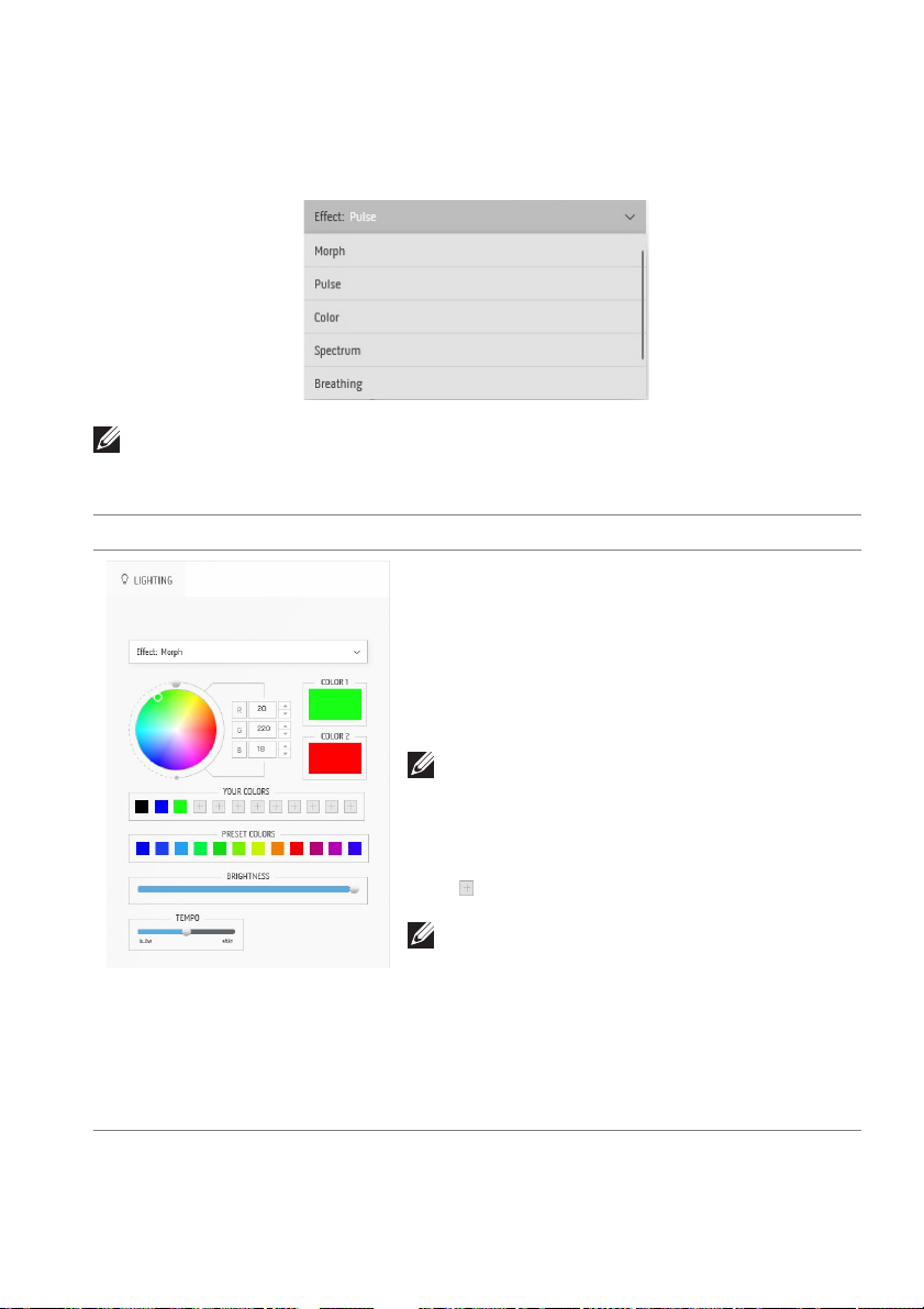
Setting lighting effects
The LIGHTING panel provides various lighting effects. You may click Effect to
open a drop-down menu with available options.
NOTE: The options displayed may vary depending on the lighting zone(s)
you specified.
The following table provides an
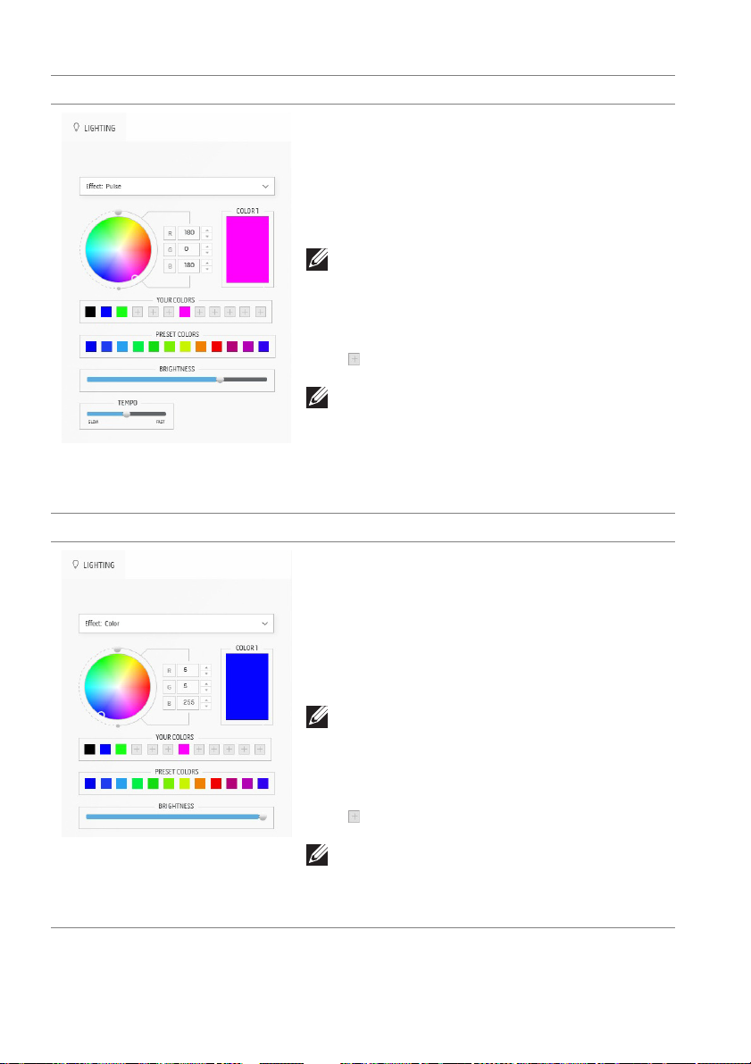
Morph Description
overview of different options:
The effect changes the light color into another
through a seamless transition.
To adjust the morph:
1. Pick a preferred color from the color palette
or the list of PRESET COLORS. The selected
color and its RGB color codes will be
displayed on the right field.
NOTE: To change the color, use the up and
down arrow buttons beside the R/G/B boxes
to edit the color codes.
2. To add the selected color to the list of YOUR
COLORS for quick access in the future, click
. At most 12 colors can be added to the list.
NOTE: To remove an existing color chip from
the list, right-click on it.
3. Repeat the previous steps to specify Color 2
to be the ending light color.
4. Drag the BRIGHTNESS slider to adjust the
brightness of the color.
5. Drag the TEMPO slider to adjust the transition
speed.
Using AlienFX application | 67
Page 68
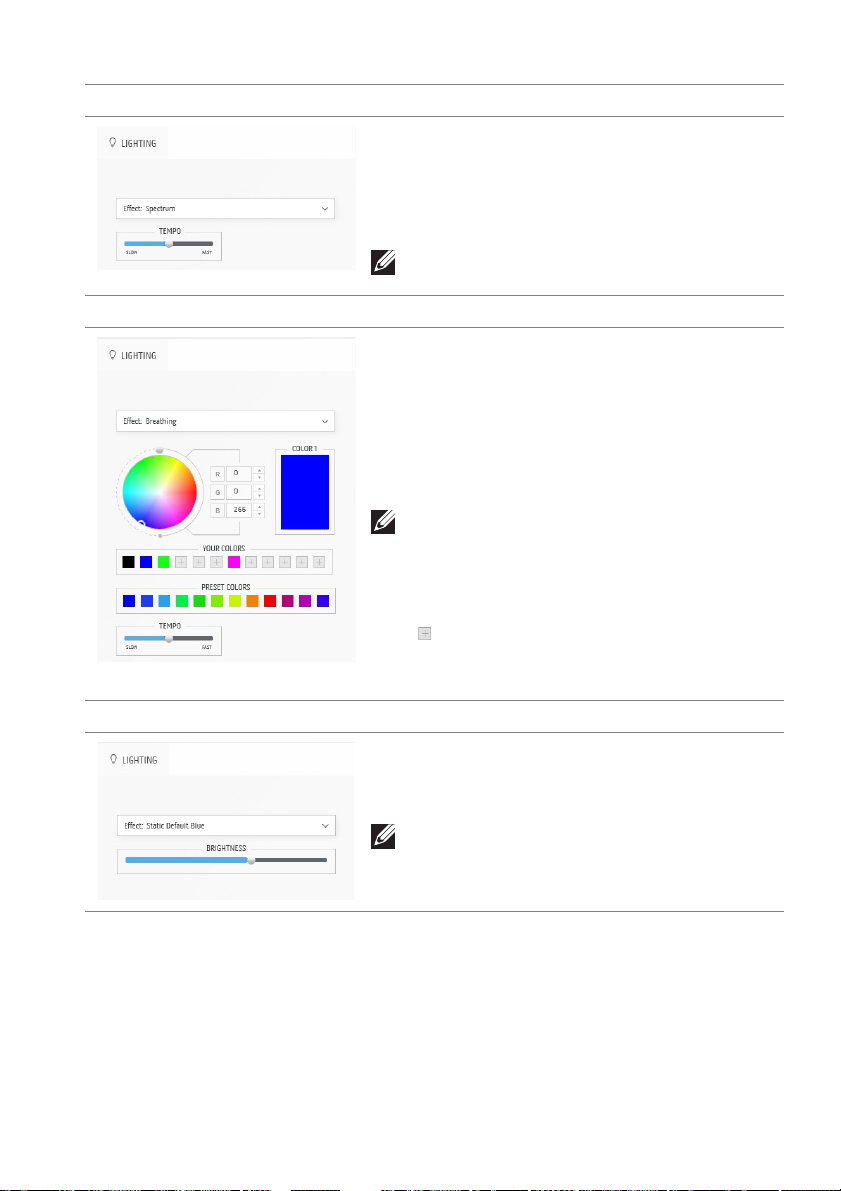
Pulse Description
The effect makes the light flash with a short pause.
To adjust the pulse:
1. Pick a preferred color from the color palette
or the list of PRESET COLORS. The selected
color and its RGB color codes will be
displayed on the right field.
NOTE: To change the color, use the up and
down arrow buttons beside the R/G/B boxes
to edit the color codes.
2. To add the selected color to the list of YOUR
COLORS for quick access in the future, click
. At most 12 colors can be added to the list.
NOTE: To remove an existing color chip from
the list, right-click on it.
3. Drag the BRIGHTNESS slider to adjust the
brightness of the color.
4. Drag the TEMPO slider to adjust the pulsing
speed.
Color Description
The effect makes the LED light in a single static
color.
To adjust the color:
1. Pick a preferred color from the color palette
or the list of PRESET COLORS. The selected
color and its RGB color codes will be
displayed on the right field.
68 | Using AlienFX application
NOTE: To change the color, use the up and
down arrow buttons beside the R/G/B boxes
to edit the color codes.
2. To add the selected color to the list of YOUR
COLORS for quick access in the future, click
. At most 12 colors can be added to the list.
NOTE: To remove an existing color chip from
the list, right-click on it.
3. Drag the BRIGHTNESS slider to adjust the
brightness of the color.
Page 69
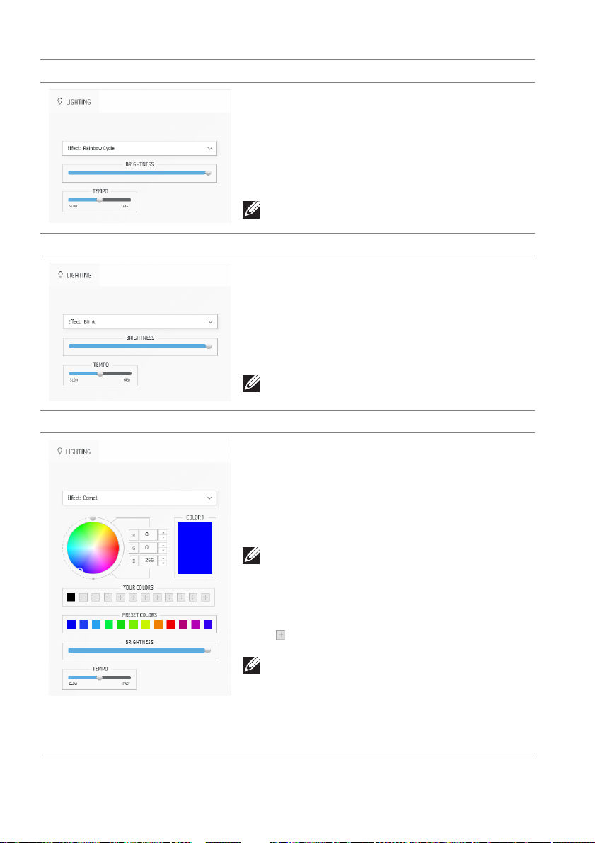
Spectrum Description
The effect makes the light change in sequence of
spectrum: red, orange, yellow, green, blue, indigo,
and violet.
You can drag the TE
transition speed.
NOTE: The option is available only when you
select All Zones to
MPO slider to adjust the
make lighting adjustments.
Breathing Description
The effect makes the light change from bright to
dim.
To adjust the breathing:
1. Pick a
2. To add the selected color to the list of YOUR
preferred color from the color palette
or the list of PRESET COLORS. The selected
color and its RGB color codes will be
displayed on the right field.
NOTE: To change the color, use the up and
down arrow buttons beside the R/G/B boxes
to edit the color codes.
COLORS for quick access in the future, click
. At most 12 colors can be added to the list.
3. Drag the TEMPO slider to adjust the transition
speed.
Static Default Blue Description
This effect makes the lights glow solid blue.
You can drag the BRI
the intensity of the color from strong to light.
GHTNESS slider to change
NOTE: The option is available only when you
select All Zones to
make lighting adjustments.
Using AlienFX application | 69
Page 70
Rainbow Cycle Description
This effect makes the lights change in the sequence
of rainbow colors.
You can drag the B
the intensity of the color from strong to light.
You can drag the TE
transition speed.
RIGHTNESS slider to change
MPO slider to adjust the
NOTE: The option is available only when
select All Zones to make lighting adjustments.
Blink Description
This effect makes the lights blink rapidly with RGB
colors.
You can drag the B
the intensity of the color from strong to light.
You can drag the TE
transition speed.
NOTE: The option is available only when
select All Zones to make lighting adjustments.
RIGHTNESS slider to change
MPO slider to adjust the
Comet Description
Select to deliver a dynamic comet light effect.
To make the adjustments:
ck a preferred color from the color palette
1. Pi
or the list of PRESET COLORS. The selected
color and its RGB color codes will be
displayed on the right field.
NOTE: To change the color, use the up and
down arrow buttons beside the R/G/B boxes
to edit the color codes.
2. To add the selected color to the list of YOUR
COLORS for quick access in the future, click
. At most 12 colors can be added to the list.
you
you
70 | Using AlienFX application
NOTE: To remove an existing color chip from
the list, right-click on it.
3. Drag the BRIGHTNESS slider to adjust the
brightness of the color.
4. Drag the TEMPO slider to adjust the pulsing
speed.
Page 71
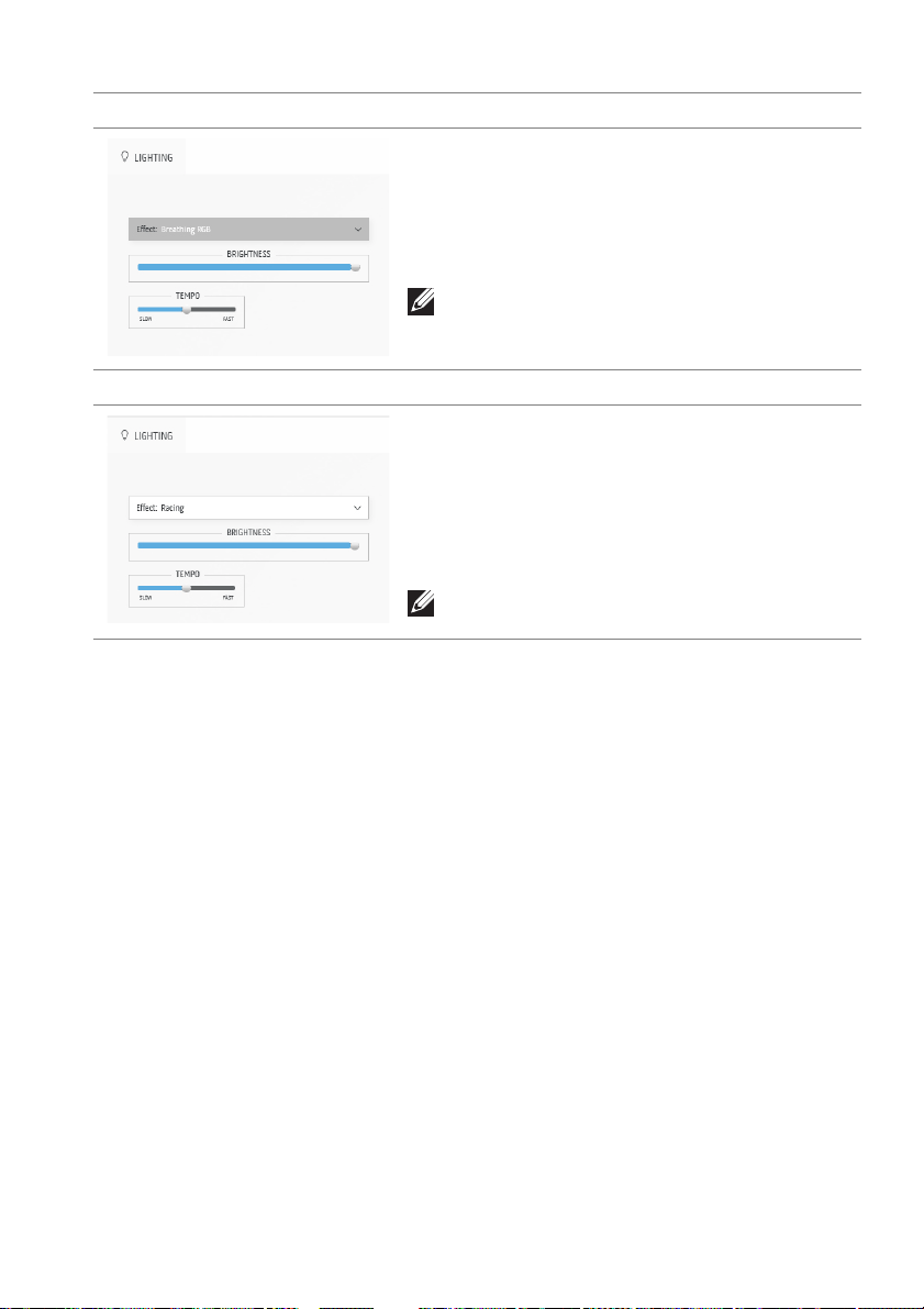
Breathing RGB Description
Select to apply a breathing RGB light effect.
You can drag the BRI
the intensity of the color from strong to light.
You can drag the TE
transition speed.
NOTE: The option is available only when you
select All Zones to
GHTNESS slider to change
MPO slider to adjust the
make lighting adjustments.
Racing Description
This effect makes the lights flash in a fast cycle of
RGB colors.
You can drag the BRI
the intensity of the color from strong to light.
You can drag the TE
transition speed.
NOTE: The option is available only when you
select All Zones to
GHTNESS slider to change
MPO slider to adjust the
make lighting adjustments.
Using AlienFX application | 71
Page 72

Troubleshooting
WARNING: Before you begin any of the procedures in this section,
follow the Safety instructions.
Self-test
Your monitor provides a self-test feature that allows you to check whether your
monitor is functioning properly. If your monitor and computer are properly
connected but the monitor screen remains dark, run the monitor self-test by
performing the following steps:
n off both your computer and the monitor.
1. Tur
2. Unplug the
3. Tur
n on the monitor.
NOTE: A dialog box should appear on the screen, indicating that the
monitor is working correctly and it is not receiving a video signal. While in
self-test mode, the power LED blinks white (default color).
video cable from the computer.
When Eco Mode is On
When Eco Mode is Off
NOTE: This dialog box also appears during normal operation, if the video
cable is disconnected or damaged.
72 | Troubleshooting
Page 73

4. Turn off your monitor and reconnect the video cable; then turn on both
your computer and the monitor.
After performing the above steps, if the monitor displays no video output, then
the problem may be with the graphics card or the computer.
Built-in diagnostics
Your monitor has a built-in diagnostic tool that helps you determine if the screen
abnormality you are experiencing is an inherent problem with your monitor, or
with your computer and video card.
NOTE: You can run the built-in diagnostics only when the video cable is
unplugged and the monitor is in self-test mode.
To run the built-in diagnostics:
1. Ensure that the screen is clean (no dust particles on the surface of the
screen).
2. Move and hold the joystick left for five seconds. A gray screen appears
after one second.
3. Observe if the screen has any defects or abnormalities.
4. Press the joystick. The color of the screen changes to red.
5. Observe if the screen has any defects or abnormalities.
6. Repeat steps 4 and 5 to inspect the display in green, blue, black, and white
screens.
The test is complete when the white screen appears. To exit, press the joystick
again.
If you do not detect any screen abnormalities upon using the built-in diagnostic
tool, the monitor is functioning properly. Check the video card and computer.
Troubleshooting | 73
Page 74

Common problems
The following table contains general information about common monitor
problems you might encounter and the possible solutions:
Common
symptoms
No video/
power LED off
No video/
power LED on
Poor focus Picture is fuzzy,
Shaky/jittery
video
What you
experience
No picture • Ensure that the video cable connecting
No picture or no
brightness
blurry, or
ghosting
Wavy picture or
fine movement
Possible solutions
the monitor and the computer is properly
connected and secure.
• Verify that the power outlet is
functioning properly using any other
electrical equipment.
• Ensure that the power button is
depressed fully.
• Ensure that the correct input source is
selected in the
• Increase brightness and contrast controls
in the
Brightness/Contrast menu.
• Perform monitor self-test feature check.
• Check for bent or broken pins in the
video cable connector.
• Run the built-in diagnostics.
• Ensure that the correct input source is
selected in the
• Eliminate video extension cables.
• Reset the monitor to factory settings.
• Change the video resolution to the
correct aspect ratio.
• Reset the monitor to factory settings.
• Check environmental factors.
• Relocate the monitor and test in another
room.
Input Source menu.
Input Source menu.
74 | Troubleshooting
Page 75

Common
symptoms
Missing pixels OLED screen has
Stuck-on pixels OLED screen has
Brightness
problems
Geometric
distortion
Horizontal/
vertical lines
Synchronization
problems
What you
experience
spots
bright spots
Picture too dim
or too bright
Screen not
centered
correctly
Screen has one
or more lines
Screen is
scrambled or
appears torn
Possible solutions
• Cycle power On-Off.
• Pixel that is permanently off is a natural
defect that can occur in OLED
technology.
• For more information on Dell Monitor
Quality and Pixel Policy, see Dell support
site:
www.dell.com/pixelguidelines.
• Cycle power On-Off.
• Pixel that is permanently off is a natural
defect that can occur in OLED
technology.
• For more information on Dell Monitor
Quality and Pixel Policy, see Dell support
site:
www.dell.com/pixelguidelines.
• Reset the monitor to factory settings.
• Adjust brightness and contrast controls in
the
Brightness/Contrast menu.
Reset the monitor to factory settings.
• Reset the monitor to factory settings.
• Perform monitor self-test feature check
and determine if these lines are also in
self-test mode.
• Check for bent or broken pins in the
video cable connector.
• Run the built-in diagnostics.
• Reset the monitor to factory settings.
• Perform monitor self-test feature check
to determine if the scrambled screen
appears in self-test mode.
• Check for bent or broken pins in the
video cable connector.
• Restart the computer in the safe mode.
Troubleshooting | 75
Page 76

Common
symptoms
Safety related
issues
Intermittent
problems
Missing color Picture missing
Wrong color Picture color not
Wrong color in
HDR mode
What you
experience
Visible signs of
smoke or sparks
Monitor
malfunctions on
and off
color
good
Color banding in
the pictures
Possible solutions
• Do not perform any troubleshooting
steps.
• Contact Dell immediately.
• Ensure that the video cable connecting
the monitor to the computer is
connected properly and is secure.
• Reset the monitor to factory settings.
• Perform monitor self-test feature check
to determine if the intermittent problem
occurs in self-test mode.
• Perform monitor self-test feature check.
• Ensure that the video cable connecting
the monitor to the computer is
connected properly and is secure.
• Check for bent or broken pins in the
video cable connector.
• Change the settings of the Preset
Modes in the Game menu OSD
depending on the application.
•Adjust R/G/B value under Custom
Color in the Game menu OSD.
• Run the built-in diagnostics.
Try to lower down the frequency (DP:
3440 x 1440 at 144
1440 at
60 Hz).
Hz, HDMI: 3440 x
76 | Troubleshooting
Page 77

Product specific problems
Specific symptoms What you experience Possible solutions
Screen image is too
small
Cannot adjust the
monitor with the
joystick
No input signal
when user controls
are pressed
The picture does not
fill the entire screen
The displayed
pictures appear
incorrectly when the
DP/HDMI cable is
connected through
a USB-C adapter or
dock to your laptop
or desktop
Image is centered on
screen, but does not fill
entire viewing area
OSD does not appear
on the screen
No picture, the LED
light
is white
The picture cannot fill
the height or width of
the screen
Display will freeze, has
black screen or display
abnormal screen
Reset the monitor to factory
settings.
Turn off the monitor, unplug the
power cord, plug it back, and
then turn on the monitor.
• Check the signal source. Ensure
that the computer is not in the
power saving mode by moving
the mouse or pressing any key
on the keyboard.
• Check whether the signal cable
is plugged in properly. Replug the signal cable if
necessary.
• Reset the computer or video
player.
• Due to different video formats
(aspect ratio), the monitor may
display in full screen.
• Run the built-in diagnostics.
Do not use a USB-C adapter or
dock. Connect the DP/HDMI
cable directly to your laptop or
desktop.
Troubleshooting | 77
Page 78

Specific symptoms What you experience Possible solutions
Screen flickering There are some
noticeable flickering in
the displayed pictures
Image retention
from a static image
left on the monitor
for a long period of
time
Unevenness in
luminance or color
of the screen images
Faint shadow from the
static image displayed
appears on the screen
Visible spots (bright or
dark) or lines or Mura
appear on the screen
• Use the native resolution of
your monitor (3440 x 1440 at
60
Hz) or higher refresh rate.
• If the variable refresh rate
(VRR) of your device is turned
on, turn off variable refresh
rate (VRR).
• If you are using an NVIDIA
graphics card and G-Sync is
turned on, turn off G-Sync.
• If you are using an AMD
graphics card and Free-Sync is
turned on, turn off Free-Sync.
• Update the graphics card
driver and firmware to the
latest version.
• Change the cable connecting
the monitor to the computer. A
defective cable can cause the
signal to break while being
transmitted across the wire.
• Check the surroundings.
Electromagnetic fields can
cause screen flickering. If there
is another device plugged into
the same power strip as the
monitor, try to remove it.
• Set the screen to turn off after
a few minutes of screen idle
time. These can be adjusted in
Windows Power Options or
Mac Energy Saver setting.
• Alternatively, use a dynamically
changing screensaver.
• Perform the function of Pixel
Refresh or Panel Refresh. See
OLED Panel Maintenance.
78 | Troubleshooting
Page 79

Specific symptoms What you experience Possible solutions
In the HDR Peak
1000 mode, the
displayed images
are dimmer than
they are in the HDR
400 True Black
mode
Pixel shifting occurs The image on the
Fan problem The fan inside the
The HDR Peak 1000
mode is ideal for the
HDR content with a
peak brightness of
1000 nits. When
displaying non-HDR
content, such as
browsers and editors,
the brightness level in
the HDR Peak 1000
mode is observed to
be lower as compared
to that in the HDR
400 True Black mode
due to the luminance
control method of
OLED panels
screen moves slightly
sometimes.
monitor keeps running
in sleep mode or when
DC is off
.
• For displaying non-HDR
content, such as Office
applications, disable the HDR
display feature in Windows
display settings.
• For displaying HDR videos or
games with a maximum peak
brightness of 1000 nits, set
HDR Mode to HDR Peak
1000.
• For displaying HDR videos or
games which meet the
DisplayHDR 400 True Black
standard, set HDR Mode to
HDR 400 True Black.
Pixel shift is a function that moves
the pixels of the screen to prevent
image retention on QD-OLED
panels. It does not influence your
viewing experience.
This is a normal activity that the
fan runs continuously for about 9
minutes after the DC is off or your
computer goes into sleep mode.
Troubleshooting | 79
Page 80

Universal Serial Bus (USB) specific problems
Specific
symptoms
USB interface is
not working
SuperSpeed
USB 5 Gbps
B 3.2 Gen 1)
(US
rface is slow
inte
Wireless USB
per
ipherals stop
working when a
USB 3.2 device
is plugged in
What you
experience
USB peripherals
are not
SuperSpeed USB
5 Gbps (USB 3.2
Gen 1) peripherals
work
not working at all
Wireless USB
pe
responding slowly
or only working as
the distance
between itself and
its receiver
decreases
working
ing slowly or
ripherals
Possible solutions
• Check that your monitor is turned on.
• Reconnect the upstream cable to your
co
mputer.
• Reconnect the USB peripherals
(downs
• Switch off and then turn on the
monitor agai
• Reboot the computer.
• Some USB devices like external
por
current; connect the device directly to
the computer system.
• Check that your computer is
S
Gen 1)-compatible.
• Some computers have USB 3.2,
USB 2.0, and USB 1.1 ports. Ensure
that the
• Reconnect the upstream cable to your
co
• Reconnect the USB peripherals
(downs
• Reboot the computer.
• Increase the distance between the
USB 3.2 peripherals and the wireless
USB receiver.
• Position your wireless USB receiver as
c
peripherals.
• Use a USB-extender cable to position
the
as possible from the USB 3.2 port.
tream connector).
n.
table HDD require higher electric
uperSpeed USB 5 Gbps (USB 3.2
correct USB port is used.
mputer.
tream connector).
lose as possible to the wireless USB
wireless USB receiver as far away
80 | Troubleshooting
Page 81

Appendix
FCC notices (U.S. only) and other regulatory information
For FCC notices and other regulatory information, see the regulatory
compliance website located at
Contact Dell
For customers in the United States, call 800-WWW-DELL (800-999-3355).
NOTE: If you do not have an active Internet connection, you can find
contact information on your purchase invoice, packing slip, bill, or Dell
product catalog.
Dell provides several online and telephone-based support and service
options. Availability varies by country and product, and some services may
not be available in your area.
• Online technical assistance: www.dell.com/support/monitors
• Contacting Dell: www.dell.com/contactdell
EU product database for energy label and product information sheet
AW3423DW: https://eprel.ec.europa.eu/qr/1049154
www.dell.com/regulatory_compliance.
Appendix | 81
 Loading...