

Dell Alienware Aurora ALX, AURORA, ALIENWARE AURORA Service Manual

01
01
/
ALIENWARE® AURORA
SERVICE MANUAL
02
02
/
e contents herein are subject to change without notice.
©2009-2010 Dell Inc. All rights reserved.
Reproduction of these materials in any manner whatsoever without the prior
written permission of Dell Inc. is strictly prohibited.
Trademarks used in this manual:
Alienware
is a registered trademark of Alienware
Corporation;
Dell
and the
DELL
logo are trademarks of Dell Inc.;
Bluetooth
is
a registered trademark owned by Bluetooth SIG, Inc. and is used by Dell under
license;
Microsoft, Windows
, and the
Windows
start button logo are either
trademarks or registered trademarks of Microsoft Corporation in the United
States and/or other countries;
Intel
and
SpeedStep
are registered trademarks of
Intel Corporation in the U.S. and other countries.
Other trademarks and trade names may be used in this manual to refer to either
the entities claiming the marks and names or their products. Dell Inc. disclaims
any proprietary interest in trademarks and trade names other than its own.
Model: D0IM Type: D0IM001; D0IM002 Rev. A01 FEBRUARY 2010
Notes, Cautions, and Warnings
NOTE: A NOTE indicates important information that helps you make better
use of your computer.
CAUTION: A CAUTION indicates either potential damage to hardware or
loss of data and tells you how to avoid the problem.
WARNING: A WARNING indicates a potential for property damage,
personal injury, or death.

03
03
/
CONTENTS
CONTENTS
CHAPTER 1: BEFORE YOU BEGIN......................................... 6
Recommended Tools ..............................................7
Turning O Your Computer ........................................ 7
Before Working Inside Your Computer . . . . . . . . . . . . . . . . . . . . . . . . . . . . . . 8
CHAPTER 2: LEFT SIDE-PANEL .......................................... 9
Removing the Left Side-Panel .....................................11
Replacing the Left Side-Panel......................................11
CHAPTER 3: TECHNICAL OVERVIEW .....................................12
Inside View of Your Computer .....................................13
System Board Components....................................... 14
Master I/O Board Components ....................................15
CHAPTER 4: SHROUDS .................................................16
Opening the PCI Shroud .......................................... 18
Closing the PCI Shroud ........................................... 18
Removing the Drive-Bay Shroud .................................. 19
Replacing the Drive-Bay Shroud................................... 19
CHAPTER 5: DRIVE(S) .................................................20
Removing the Hard Drive(s) ......................................22
Replacing the Hard Drive(s).......................................24
Removing the Optical Drive(s) ....................................25
Replacing the Optical Drive(s).....................................26
Removing the Media Card Reader .................................27
Replacing the Media Card Reader .................................29
CHAPTER 6: PCI-EXPRESS CARD(S) ....................................30
Removing the PCI-Express Card(s) ................................32
Replacing the PCI-Express Card(s).................................33
CHAPTER 7: MEMORY MODULE(S)...................................... 35
Removing the Memory Module(s) .................................37
Replacing the Memory Module(s) .................................38

04
04
/
CONTENTS
CHAPTER 13: SYSTEM BOARD ..........................................66
Removing the System Board......................................68
Replacing the System Board ......................................69
CHAPTER 14: MASTER I/O BOARD ......................................70
Removing the Master I/O Board...................................72
Replacing the Master I/O Board ...................................73
CHAPTER 15: TOP LIGHTING-BOARD.................................... 74
Removing the Top Lighting-Board ................................76
Replacing the Top Lighting-Board.................................76
CHAPTER 16: RIGHT SIDE-PANEL(S) .....................................77
Removing the Right Side-Panel(s) ................................79
Replacing the Right Side-Panel(s)................................. 81
CHAPTER 17: ACTIVE-VENTING ASSEMBLY ..............................82
Removing the Active-Venting Assembly...........................84
Replacing the Active-Venting Assembly ...........................87
CHAPTER 18: FRONT BEZEL ............................................88
Removing the Front Bezel ........................................90
Replacing the Front Bezel ........................................92
CHAPTER 8: FANS.....................................................40
Removing the Hard-Drive Fan Assembly...........................42
Replacing the Hard-Drive Fan Assembly ...........................43
Removing the PCI-Fan Assembly..................................44
Replacing the PCI-Fan Assembly ..................................45
CHAPTER 9: PROCESSOR LIQUID-COOLING ASSEMBLY...................46
Removing the Processor Liquid-Cooling Assembly .................48
Replacing the Processor Liquid-Cooling Assembly .................49
CHAPTER 10: PROCESSOR .............................................50
Removing the Processor..........................................52
Replacing the Processor ..........................................53
CHAPTER 11: POWER SUPPLY ..........................................55
Removing the Power Supply . . . . . . . . . . . . . . . . . . . . . . . . . . . . . . . . . . . . . . 57
Replacing the Power Supply ......................................59
CHAPTER 12: BATTERY ................................................60
Removing the Coin-Cell Battery ...................................62
Replacing the Coin-Cell Battery ...................................63
Removing the eater-Lighting Batteries .........................64
Replacing the eater-Lighting Batteries..........................65

05
05
/
CONTENTS
CHAPTER 19: BACK BEZEL .............................................93
Removing the Back Bezel.........................................95
Replacing the Back Bezel .........................................97
CHAPTER 20: BLUETOOTH ASSEMBLY..................................98
Removing the Bluetooth Assembly...............................100
Replacing the Bluetooth Assembly............................... 101
CHAPTER 21: TOP I/O PANEL ..........................................102
Removing the Top I/O Panel .....................................104
Replacing the Top I/O Panel......................................105
CHAPTER 22: SYSTEM SETUP .........................................106
Conguring the BIOS ............................................107
Clearing Forgotten Passwords and CMOS Settings .................114
APPENDIX A: CONTACTING ALIENWARE ................................117

CHAPTER 1: B EFORE YOU BEGIN
06
06
/
is manual provides procedures for removing and installing the components
in your computer. Unless otherwise noted, each procedure assumes that the
following conditions exist:
You have performed the steps in “Turning O Your Computer” on page • 7 and
“Before Working Inside Your Computer” on page 8.
You have read the safety information that shipped with your computer.•
A component can be replaced or—if purchased separately—installed by •
performing the removal procedure in reverse order.
CHAPTER 1: BEFORE YOU BEGIN
CHAPTER 1: BEFORE YOU BEGIN

07
07
/
CHAPTER 1: B EFORE YOU BEGIN
Turning O Your Computer
CAUTION: To avoid losing data, save and close all open les and exit all
open programs before you turn o your computer.
Save and close all open les and exit all open programs.1.
Click 2. Start → Shut Down.
e computer turns o after the operating system shutdown process 3.
nishes.
Ensure that the computer is turned o. If your computer did not 4.
automatically turn o when you shut down the operating system, press and
hold the power button until the computer turns o.
Recommended Tools
e procedures in this document may require the following tools:
Small at-blade screwdriver•
Phillips screwdriver•
BIOS executable update program available at • support.dell.com
08
08
/
CHAPTER 1: B EFORE YOU BEGIN
Ensure that the work surface is at and clean.1.
Turn o your computer (see “Turning O Your Computer” on page 2. 7).
CAUTION: To disconnect a network cable, rst unplug the cable from
your computer and then unplug the cable from the network device.
Disconnect all telephone or network cables from the computer.3.
Disconnect your computer and all attached devices from their electrical 4.
outlets.
Disconnect all attached devices from your computer.5.
Press and eject any installed cards from the Media Card Reader.6.
Press and hold the power button to ground the system board.7.
CAUTION: Before touching anything inside your computer, ground
yourself by touching an unpainted metal surface, such as the metal at the
back of the computer. While you work, periodically touch an unpainted
metal surface to dissipate static electricity, which could harm internal
components.
NOTE: For better access to components within your computer, lay your
computer on its side.
Before Working Inside Your Computer
Use the following safety guidelines to help protect your computer from potential
damage and to help to ensure your own personal safety.
WARNING: Before you begin any of the procedures in this section, follow
the safety instructions that shipped with your computer. For additional
safety best practices information, see the Regulatory Compliance
Homepage at www.dell.com/regulatory_compliance.
CAUTION: Only a certied service technician should perform repairs on
your computer. Damage due to servicing that is not authorized by Dell is
not covered by your warranty.
CAUTION: When you disconnect a cable, pull on its connector or on its
pull-tab, not on the cable itself. Some cables have connectors with locking
tabs; if you are disconnecting this type of cable, press in on the locking
tabs before you disconnect the cable. As you pull connectors apart, keep
them evenly aligned to avoid bending any connector pins. Also, before
you connect a cable, ensure that both connectors are correctly oriented
and aligned.
CAUTION: To avoid damaging the computer, perform the following steps
before you begin working inside the computer.

CHAPTER 2: LEFT SIDE-PANEL
09
09
/
CHAPTER 2: LEFT SIDE-PANEL
CHAPTER 2: SIDE PANEL
010
010
/
CHAPTER 2: LEFT SIDE-PANEL
Left Side-Panel
WARNING: Before working inside your computer, read the safety
information that shipped with your computer. For additional safety best
practices information, see the Regulatory Compliance Homepage at
www.dell.com/regulatory_compliance.
WARNING: To guard against likelihood of electric shock, laceration by
moving fan blades, or other unexpected injuries, always unplug your
computer from the electrical outlet before removing the side panel(s).
WARNING: Do not operate your computer with any cover(s) (including
computer covers, bezels, ller brackets, front-panel inserts, etc.)
removed.
CAUTION: Only a certied service technician should perform repairs on
your computer. Damage due to servicing that is not authorized by Dell™
is not covered by your warranty.

011
011
/
CHAPTER 2: LEFT SIDE-PANEL
1
3
2
4
1 release panel 2 security cable slot
3 latch 4 left side-panel
Removing the Left Side-Panel
Follow the instructions in “Before You Begin” on page 1. 6.
NOTE: Ensure that you remove the security cable from the security cable
slot (if applicable).
Slide the latch to unlock the release panel.2.
Lift the release panel to open the left-side panel.3.
Place the left side-panel in a secure location.4.
NOTE: eater lighting (available only in Alienware Aurora ALX) turns on
automatically when the left side-panel is removed.
Replacing the Left Side-Panel
Follow the instructions in “Before You Begin” on page 1. 6.
Align the tabs on the left side-panel with the slots on the side of the 2.
computer and push the panel in place.
Slide the latch to lock the release panel.3.

CHAPTER 3: T ECHNICAL OVERVIEW
012
012
/
CHAPTER 3: TECHNICAL OVERVIEW
CHAPTER 3: TECHNICAL OVERVIEW

013
013
/
CHAPTER 3: T ECHNICAL OVERVIEW
1
2
3
4
1 memory module(s) 2 graphic cards (2)
3 optical drives (3) 4 hard drives (4)
Inside View of Your Computer
WARNING: Before working inside your computer, read the safety
information that shipped with your computer. For additional safety best
practices information, see the Regulatory Compliance Homepage at
www.dell.com/regulatory_compliance.
014
014
/
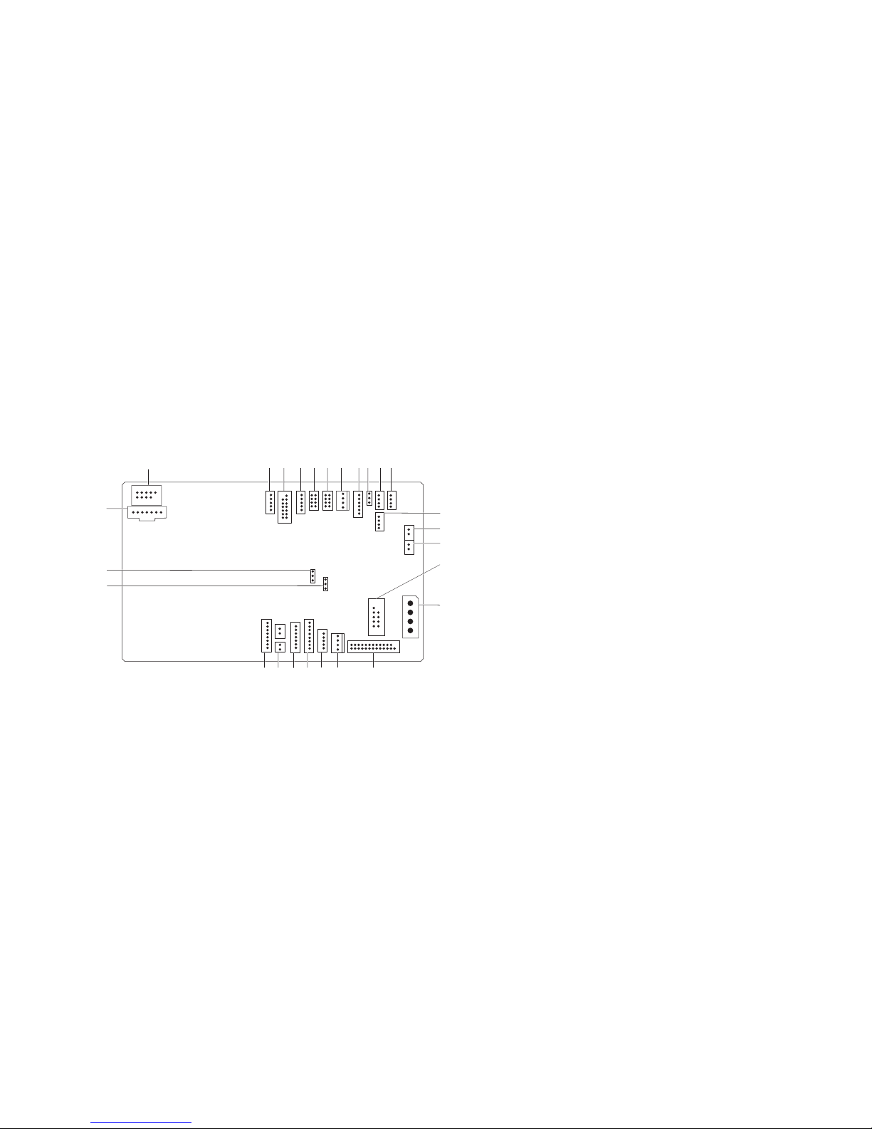
CHAPTER 3: T ECHNICAL OVERVIEW
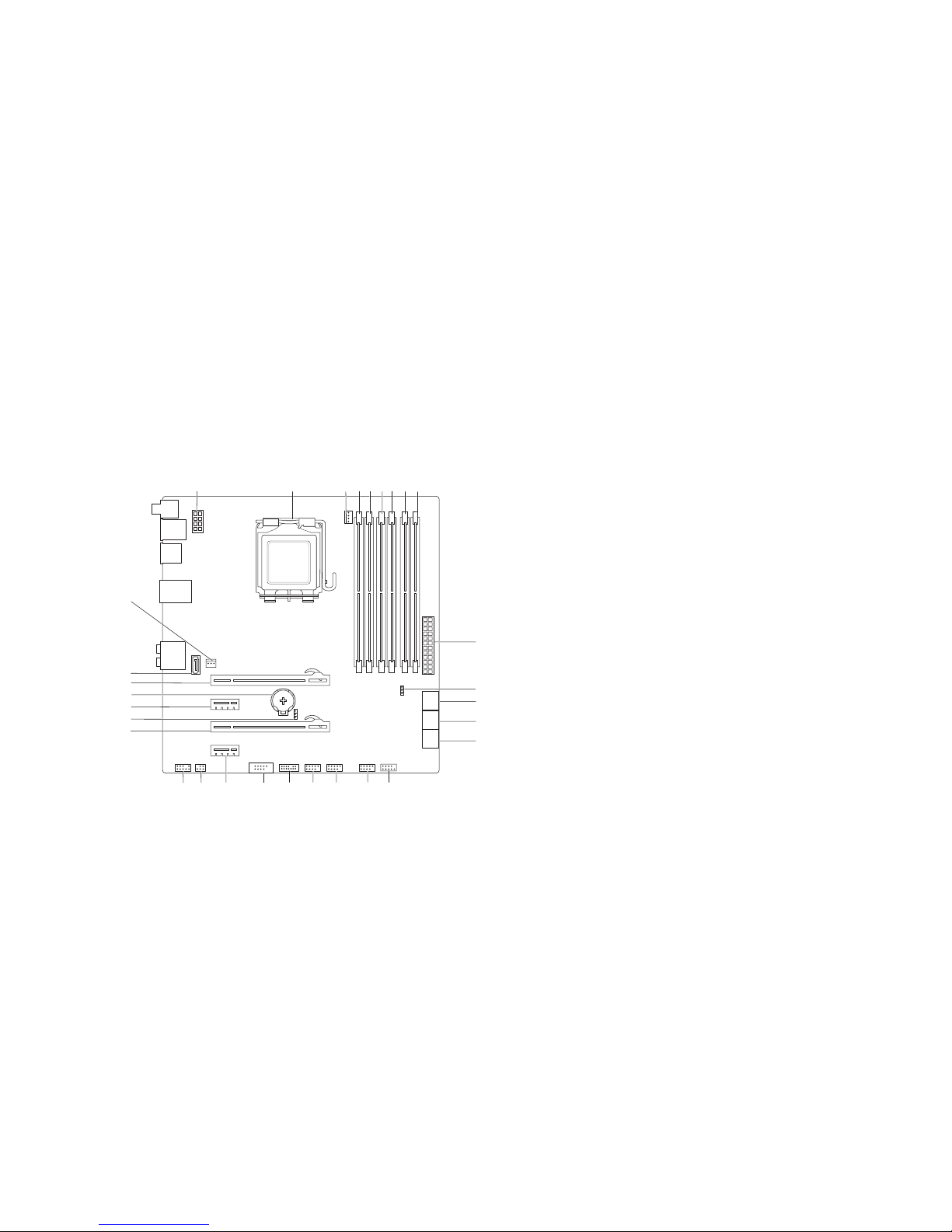
1 processor power connector (PWR2) 2 processor socket (CPU)
3 processor fan connector (MB_CPU_FAN) 4 memory-module connector (DIMM2)
(Aurora and Aurora ALX )
memory-module connector (DIMM3)
(Aurora-R2)
5 memory-module connector (DIMM1) 6 memory-module connector (DIMM4)
7 memory-module connector (DIMM3)
(Aurora and Aurora ALX)
memory-module connector (DIMM2)
(Aurora-R2)
8 memory-module connector (DIMM6)
(Aurora and Aurora ALX only)
9 memory-module connector (DIMM5)
(Aurora and Aurora ALX only)
10 main power connector (PWR1)
11 password jumper (PASSWORD) 12 serial ATA drive connectors (SATA1_2)
13 serial ATA drive connectors (SATA3_4) 14 serial ATA drive connectors (SATA5_6)
15 front panel connector (FRONT_PANEL) 16 USB connector (USB1)
17 USB connector (USB2) 18 USB connector (USB3)
19 Low pin count debug header (LPC1) 20 IEEE 1394 connector (1394)
21 PCI-Express x1 connector (SLOT4) 22 S/PDIF connector (SPDIF)
(Aurora and Aurora ALX only)
23 front audio connector (FRONT AUDIO) 24 PCI-Express x16 connector (SLOT3)
25 CMOS jumper (CLEAR_CMOS) 26 PCI-Express x1 connector (SLOT2)
27 battery socket (BAT1) 28 PCI-Express x16 connector (SLOT1)
29 eSATA connector (ESATA) 30 processor cooling assembly
connector (CHIPSET_FAN)
System Board Components
2021
2223
24
25
27
26
28
29
30
1
2 3
4
5
6 7 8
9
10
12
11
13
14
15
16
17
1819
015
015
/
CHAPTER 3: T ECHNICAL OVERVIEW
1 flexbay connector (FLEXBAY) 2 drive-bay shroud battery connector
(FRONT_BEZEL)
3 active-ven t connector
(ACTIVE_VENT)
4 AlienHead connector (HEAD1)
5 front-bezel right connector
(FRONT_RIGHT)
6 front-bezel left connector
(FRONT_LEFT)
7 PCI-fan connector (FAN_PCI) 8 left side-panel contact board
connector (SIDE_L)
9 power-select connector (PWR_SEL) 10 Bluetooth® connector (BLUETOOTH)
11 power-LED board connector (BLINK) 12 wireless connector (WIRELESS)
13 hard-drive LED connector
(HDD_LED1)
14 hard-drive LED connector
(HDD_LED2)
15 USB connector (MB_USB) 16 main-power connector (PWR1)
17 system-board lighting (MB_MIO) 18 hard-drive fan connector (FAN_HDD)
19 right side-panel connector
(SIDE_R)
20 vent-motor connector
(VENT_MOTOR1)
21 vent sensors (VENT_SW) 22 ODD sensors (ODD_SW)
23 vent-motor sensor connector
(VENT_MOTOR2)
24 internal theater-lighting connector
(BAT2)
25 front-default connector
(FACTORY_DEFAULT)
26 graphics-pump connector
(GFX_PUMP)
Master I/O Board Components
5
4
3
2
12
13
14
15
16
25
24
26
1
678 9
10 11
17
18
19
2021
22
23

CHAPTER 4: S HROUDS
016
016
/
CHAPTER 5: SHROUDS
CHAPTER 4: SHROUDS
017
017
/
CHAPTER 4: S HROUDS
Shrouds
WARNING: Before working inside your computer, read the safety
information that shipped with your computer. For additional safety best
practices information, see the Regulatory Compliance Homepage at
www.dell.com/regulatory_compliance.
WARNING: Do not operate your computer with any cover(s) (including
computer covers, bezels, ller brackets, front-panel inserts, etc.)
removed.
WARNING: To guard against electrical shock, always unplug your
computer from the electrical outlet before removing the side panel(s).
CAUTION: Only a certied service technician should perform repairs on
your computer. Damage due to servicing that is not authorized by Dell™
is not covered by your warranty.
018
018
/
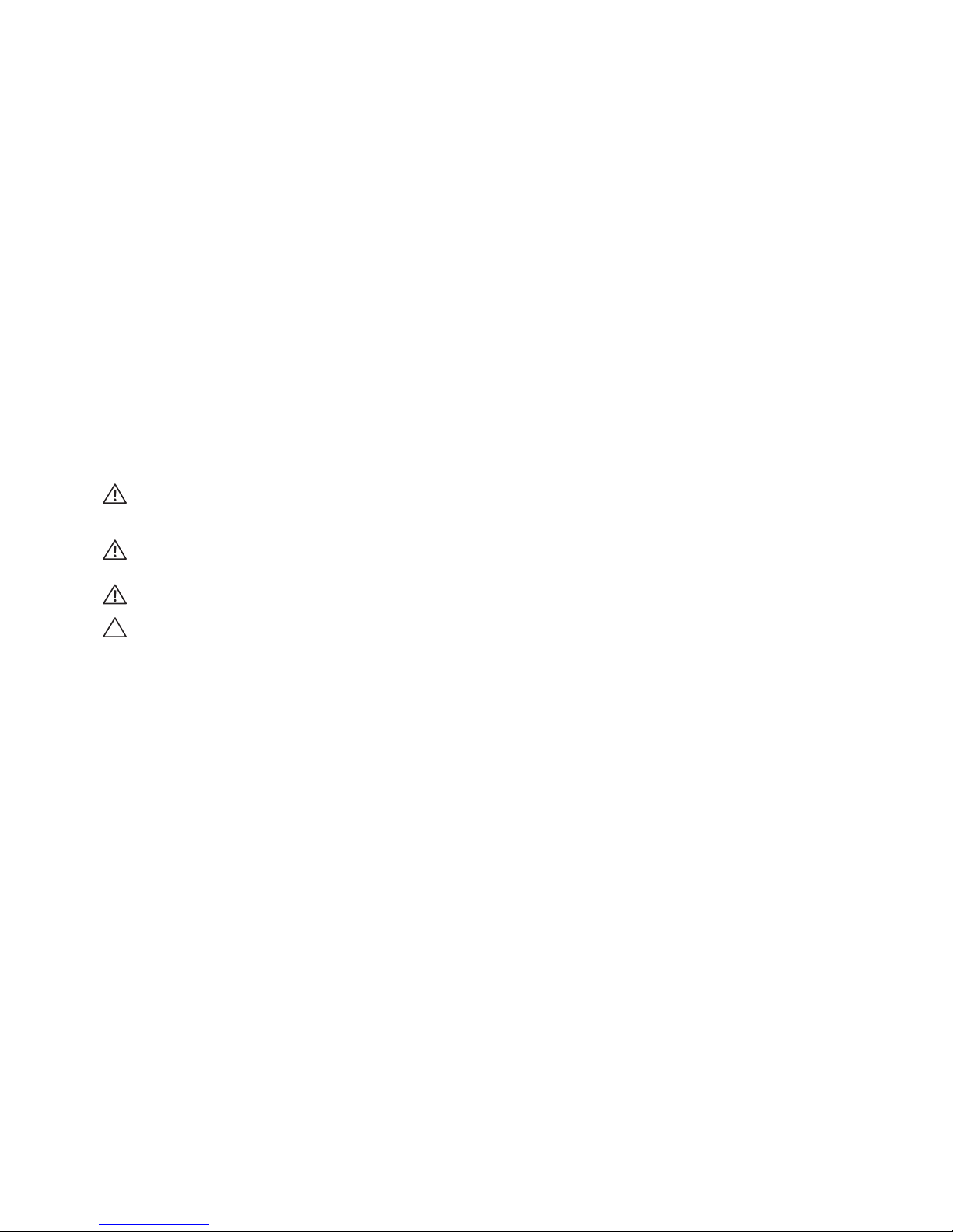
CHAPTER 4: S HROUDS
Opening the PCI Shroud
Follow the instructions in “Before You Begin” on page 1. 6.
Remove the left side-panel (see “Removing the Left Side-Panel“ on page 2. 11).
Press the release button and rotate the PCI shroud away from the chassis.3.
Closing the PCI Shroud
Follow the instructions in “Before You Begin” on page 1. 6.
Lower the PCI shroud into the chassis until it clicks into place.2.
Replace the left side-panel (see “Replacing the Left Side-Panel“ on page 3. 11).
Connect your computer and devices to electrical outlets and then turn 4.
them on.
1
2
1 release button 2 PCI shroud
019
019
/
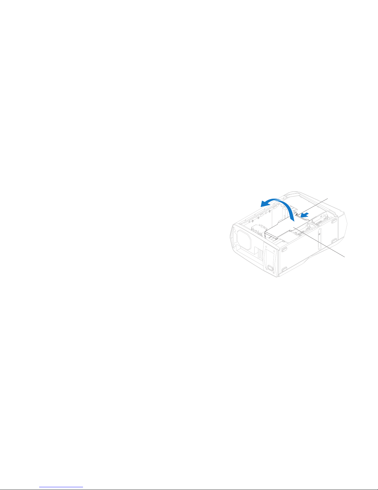
CHAPTER 4: S HROUDS
2
1
1 tabs (2) 2 drive-bay shroud
Removing the Drive-Bay Shroud
Follow the instructions in “Before You Begin” on page 1. 6.
Remove the left side-panel (see “Removing the Left Side-Panel“ on page 2. 11).
Open the PCI shroud (see “Opening the PCI Shroud” on page 3. 18).
Press the tabs and slide the drive-bay shroud towards the back of the 4.
chassis.
Disconnect the drive-bay shroud battery cable from the connector on the 5.
master I/O board.
Replacing the Drive-Bay Shroud
Follow the instructions in “Before You Begin” on page 1. 6.
Connect the drive-bay shroud battery cable to the connector on the master 2.
I/O board.
Align the drive-bay shroud with the slots on the chassis.3.
Slide the drive-bay shroud toward the front of the chassis until it clicks into 4.
place.
Close the PCI shroud (see “Closing the PCI Shroud” on page 5. 18).
Replace the left side-panel (see “Replacing the Left Side-Panel“ on page 6. 11).
Connect your computer and devices to electrical outlets and then turn 7.
them on.

CHAPTER 5: D RIVE(S)
020
020
/
CHAPTER 6: DRIVE(S)
CHAPTER 5: DRIVE(S)
021
021
/
CHAPTER 5: D RIVE(S)
Drive(s)
WARNING: Before working inside your computer, read the safety
information that shipped with your computer. For additional safety best
practices information, see the Regulatory Compliance Homepage at
www.dell.com/regulatory_compliance.
WARNING: Do not operate your computer with any cover(s) (including
computer covers, bezels, ller brackets, front-panel inserts, etc.)
removed.
WARNING: To guard against electrical shock, always unplug your
computer from the electrical outlet before removing the side panel(s).
WARNING: If you remove the hard drive from the computer when the
drive is hot, do not touch the metal housing of the hard drive.
CAUTION: Only a certied service technician should perform repairs on
your computer. Damage due to servicing that is not authorized by Dell™
is not covered by your warranty.
CAUTION: To prevent data loss, turn o your computer (see “Turning
O Your Computer” on page 7) before removing the hard drive. Do not
remove the hard drive while the computer is on or in Sleep state.
CAUTION: Hard drives are extremely fragile. Exercise care when handling
the hard drive.
CAUTION: To avoid electrostatic discharge, ground yourself by using a
wrist grounding strap or by periodically touching an unpainted metal
surface (such as a connector on the back of the computer).
NOTE: Dell does not guarantee compatibility or provide support for hard
drives from sources other than Dell or Alienware.
NOTE: If you are installing a hard drive from a source other than Dell or
Alienware, you need to install an operating system, drivers, and utilities on
the new hard drive.
022
022
/
CHAPTER 5: D RIVE(S)
Removing the Hard Drive(s)
CAUTION: If you are replacing a hard drive that contains data you want
to keep, back up your les before you begin this procedure.
Follow the instructions in “Before You Begin” on page 1. 6.
Remove the left side-panel (see “Removing the Left Side-Panel“ on page 2. 11).
Disconnect the power and data cables from the hard-drive assembly 3.
(if applicable).
2
1
1 power cable 2 data cable
023
023
/
CHAPTER 5: D RIVE(S)
Press the release tabs and slide the hard-drive assembly out of the hard- 4.
drive cage.
1
2
1 hard-drive assembly 2 release tabs (2)
Remove the hard drive out of the hard-drive bracket by releasing the tabs 5.
and lifting the hard drive out of the bracket (if applicable).
2
1
1 hard drive 2 tabs (4)

024
024
/
CHAPTER 5: D RIVE(S)
Replacing the Hard Drive(s)
Follow the instructions in “Before You Begin” on page 1. 6.
See the documentation that shipped with your new hard drive and ensure 2.
that the jumper positioning is correct.
Snap the hard-drive bracket on to the new hard drive (if applicable).3.
Slide the hard-drive assembly into the hard-drive cage until the release tabs 4.
snap into place.
Connect the power and data cables to the hard-drive assembly 5.
(if applicable).
Replace the left side-panel (see “Replacing the Left Side-Panel“ on page 6. 11).
Connect your computer and devices to electrical outlets and then turn 7.
them on.

025
025
/
CHAPTER 5: D RIVE(S)
2
3
4
1
1 power cable 2 data cable
3 securing tab 4 optical drive
Removing the Optical Drive(s)
Follow the instructions in “Before You Begin” on page 1. 6.
Press the AlienHead on the front of your computer to lower the drive panel.2.
Remove the left side-panel (see “Removing the Left Side-Panel“ on page 3. 11).
Open the PCI shroud (see “Opening the PCI Shroud” on page 4. 18).
Disconnect the power and data cables from the optical drive (if applicable).5.
Lift the securing tab and slide the optical drive out through the front of the 6.
computer.

026
026
/
CHAPTER 5: D RIVE(S)
Replacing the Optical Drive(s)
Follow the instructions in “Before You Begin” on page 1. 6.
Remove the new optical drive from its packaging. Save the original 2.
packaging for storing or shipping the optical drive.
Remove the optical-drive bay ller (if applicable).3.
Lift the securing tab and slide the optical drive through the front of the 4.
computer until the securing tab snaps into place.
Connect the power and data cables to the optical drive (if applicable).5.
Close the PCI shroud (see “Closing the PCI Shroud” on page 6. 18).
Replace the left side-panel (see “Replacing the Left Side-Panel“ on page 7. 11).
Lift the drive panel towards the top of your computer.8.
Connect your computer and devices to electrical outlets and then turn 9.
them on.
027
027
/
CHAPTER 5: D RIVE(S)
3
1
2
1 FlexBay USB cable 2 securing tab
3 FlexBay dock
Removing the Media Card Reader
Follow the instructions in “Before You Begin” on page 1. 6.
Press the AlienHead on the front of your computer to lower the drive panel.2.
Remove the left side-panel (see “Removing the Left Side-Panel“ on page 3. 11).
Open the PCI shroud (see “Opening the PCI Shroud” on page 4. 18).
Disconnect the FlexBay USB cable from the connector on the master I/O 5.
board.
Lift the securing tab and slide the FlexBay dock out through the front of the 6.
computer.
028
028
/
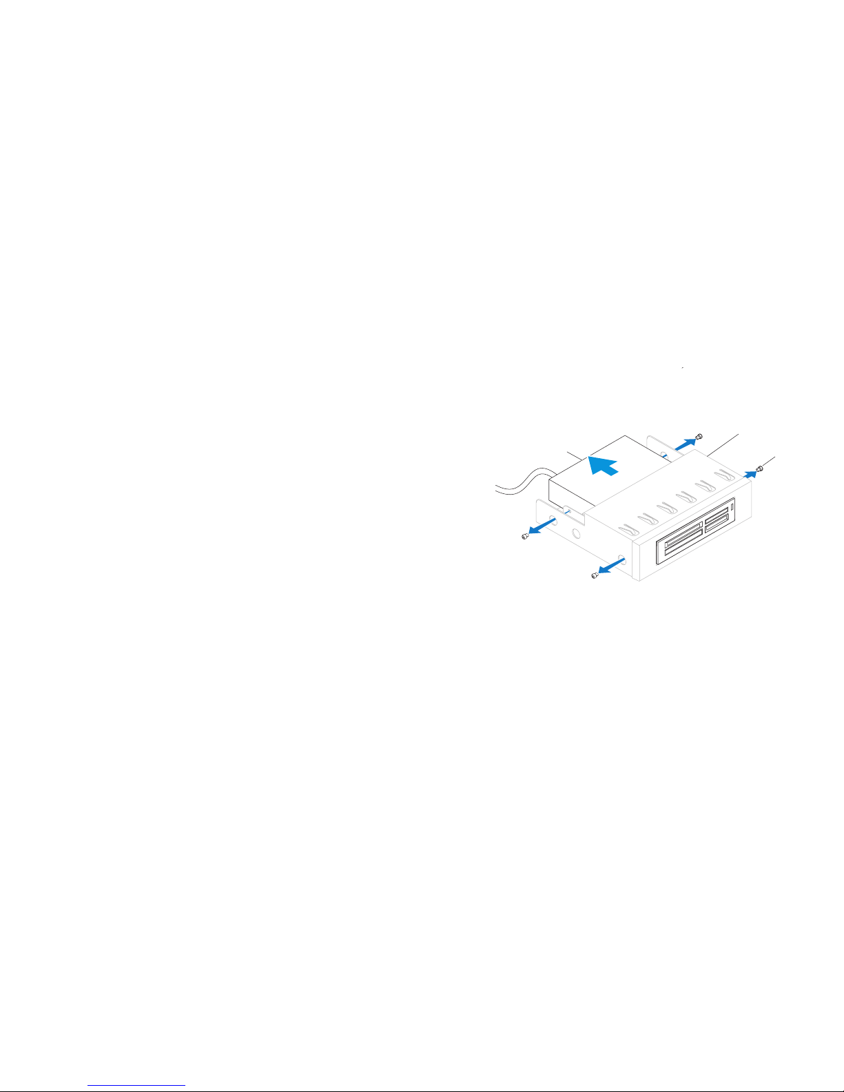
CHAPTER 5: D RIVE(S)
1
3
2
1 Media Card Reader 2 FlexBay dock
3 screws (4)
Remove the four screws that secure the Media Card Reader to the FlexBay 7.
dock.
Slide the Media Card Reader out of the FlexBay dock.8.

029
029
/
CHAPTER 5: D RIVE(S)
Replacing the Media Card Reader
Follow the instructions in “Before You Begin” on page 1. 6.
Remove the new Media Card Reader from its packaging. Save the original 2.
packaging for storing or shipping the Media Card Reader.
Slide the Media Card Reader into the FlexBay dock.3.
Replace the four screws that secure the Media Card Reader to the FlexBay 4.
dock.
Lift the securing tab and slide the FlexBay dock through the front of the 5.
computer until the securing tab snaps into place.
Connect the FlexBay USB cable to the connector on the master I/O board.6.
Close the PCI shroud (see “Closing the PCI Shroud” on page 7. 18).
Replace the left side-panel (see “Replacing the Left Side-Panel“ on page 8. 11).
Lift the drive panel towards the top of your computer.9.
Connect your computer and devices to electrical outlets and then turn 10.
them on.

CHAPTER 6: PCI-EXPRESS CARD(S)
030
030
/
CHAPTER 6: PCI EXPRESS CARD(S)
CHAPTER 6: PCI-EXPRESS CARD(S)
 Loading...