

Dell PowerConnect W-Series FIPS, Aruba 620, Aruba 650, Dell W- 620, Dell W-650 Supplement Manual

Aruba 620, 650 and Dell W-
620, W-650
Controllers with ArubaOS FIPS
Firmware Non-Proprietary Security
Policy FIPS 140-2 Level 2 Release
Supplement

Copyright
®
© 2011 Aruba Networks, Inc. Aruba Networks trademarks include , Aruba Networks
registered Aruba the Mobile Edge Company logo, Aruba Mobility Management System
Networks Must Follow
Open Source Code
Certain Aruba products include Open Source software code developed by third parties, including software code subject to the GNU
General Public License (GPL), GNU Lesser General Public License (LGPL), or other Open Source Licenses. The Open Source code used
can be found at this site:
®
, RFProtect®, Green Island®. All rights reserved. All other trademarks are the property of their respective owners.
®
, Mobile Edge Architecture®, People Move.
, Aruba Wireless Networks®, the
http://www.arubanetworks.com/open_source
Legal Notice
The use of Aruba Networks, Inc. switching platforms and software, by all individuals or corporations, to terminate other vendors’ VPN
client devices constitutes complete acceptance of liability by that individual or corporation for this action and indemnifies, in full, Aruba
Networks, Inc. from any and all legal actions that might be taken against it with respect to infringement of copyright on behalf of those
vendors.
Warranty
This hardware product is protected by the standard Aruba warranty of one year parts/labor. For more information, refer to the
ARUBACARE SERVICE AND SUPPORT TERMS AND CONDITIONS.
Altering this device (such as painting it) voids the warranty.
Copyright
© 2011 Aruba Networks, Inc. Aruba Networks trademarks include , Aruba Networks®, Aruba Wireless Networks®,the registered Aruba
the Mobile Edge Company logo, and Aruba Mobility Management System®. Dell™, the DELL™ logo, andPowerConnect™ are trademarks
of Dell Inc.
www.arubanetworks.com
1344 Crossman Avenue
Sunnyvale, California 94089
Phone: 408.227.4500
Fax 408.227.4550
Aruba 620, 650 and Dell W-620, W-650 | FIPS 140-2 Level 2 Release Supplement 0510888-02 | October 2011

Contents
Preface ...................................................................................................................................5
Purpose of this Document.....................................................................................5
Aruba Dell Relationship...................................................................................5
Related Documents ...............................................................................................6
Product Manuals.............................................................................................6
Additional Product Information .......................................................................6
Chapter 1 The Aruba 620 and 650 Mobility Controllers ......................................... 7
Overview................................................................................................................7
Physical Description ..............................................................................................8
Dimensions......................................................................................................8
Cryptographic Module Boundaries .......................................................................8
Aruba 620 Chassis ..........................................................................................8
Aruba 650 Chassis ........................................................................................11
Chapter 2 FIPS 140-2 Level 2 Features .................................................................15
Intended Level of Security...................................................................................15
Physical Security .................................................................................................15
Operational Environment .....................................................................................15
Logical Interfaces ................................................................................................16
Roles and Services ..............................................................................................17
Crypto Officer Role .......................................................................................17
User Role.......................................................................................................19
Authentication Mechanisms..........................................................................20
Unauthenticated Services .............................................................................20
Cryptographic Key Management.........................................................................21
Implemented Algorithms ...............................................................................21
Non-FIPS Approved Algorithms....................................................................21
Critical Security Parameters..........................................................................22
Self-Tests.............................................................................................................25
Alternating Bypass State .....................................................................................26
Mitigation of Other Attacks..................................................................................26
XSec..............................................................................................................26
Wireless Intrusion Detection .........................................................................27
Unique Station and User Classification ..................................................27
Detecting and Disabling Rogue APs ......................................................27
Denial of Service and Impersonation Protection...........................................27
Man-in-the-Middle Protection.......................................................................27
Policy Definition and Enforcement................................................................28
Using Wireless to Protect your Wired Network.............................................28
Using Wireless to Protect your Existing Wireless Network...........................28
Chapter 3 Installing the Controller......................................................................... 29
Aruba 620, 650 and Dell W-620, W-650 | FIPS 140-2 Level 2 Release Supplement | 3
Pre-Installation Checklist.....................................................................................29
Precautions..........................................................................................................29
The Security Kit ...................................................................................................30

Product Examination.....................................................................................30
Package Contents.........................................................................................30
Tamper-Evident Labels .......................................................................................30
Reading TELs................................................................................................31
Required TEL Locations................................................................................31
Aruba 620 ...............................................................................................31
Aruba 650 ...............................................................................................34
Applying TELs ...............................................................................................36
Chapter 4 Ongoing Management...........................................................................37
Crypto Officer Management ................................................................................37
User Guidance.....................................................................................................37
Chapter 5 Setup and Configuration .......................................................................39
Setting Up Your Controller ..................................................................................39
Enabling FIPS Mode ............................................................................................39
Enabling FIPS with the Setup Wizard ...........................................................39
Enabling FIPS with the WebUI ......................................................................39
Disallowed FIPS Mode Configurations................................................................40
4 | Aruba 620, 650 and Dell W-620, W-650 | FIPS 140-2 Level 2 Release Supplement
Preface
This security policy document can be copied and distributed freely.
Purpose of this Document
This release supplement provides information regarding the Aruba 620 and 650 Mobility Controllers and
Dell W-620 and W-650 controllers with FIPS 140-2 Level 2 validation from Aruba Networks. The material in
this supplement modifies the general Aruba hardware and firmware documentation included with this
product and should be kept with your Aruba product documentation.
This supplement primarily covers the non-proprietary Cryptographic Module Security Policy for the Aruba
Mobility Controller. This security policy describes how the switch meets the security requirements of FIPS
140-2 Level 2 and how to place and maintain the switch in a secure FIPS 140-2 mode. This policy was
prepared as part of the FIPS 140-2 Level 2 validation of the product.
FIPS 140-2 (Federal Information Processing Standards Publication 140-2, Security Requirements for
Cryptographic Modules) details the U.S. Government requirements for cryptographic modules. More
information about the FIPS 140-2 standard and validation program is available on the National Institute of
Standards and Technology (NIST) Web-site at:
http://csrc.nist.gov/groups/STM/cmvp/index.html
Aruba Dell Relationship
Aruba Networks is the OEM for the Dell PowerConnect W line of products. Dell products are identical to
the Aruba products other than branding and Dell software is identical to Aruba software other than
branding.
The contents of this document will use the Aruba 620 and 650 as examples and all corresponding Dell
models follow the same rules.
Table 1 Aruba and Dell Part Numbers
Aruba Part Number Corresponding Dell Part Number
620-F1 W-620-F1
620-USF1 W-620-USF1
650-F1 W-650-F1
650-USF1 W-650-USF1
References to Aruba, ArubaOS and Aruba 600 series apply to both the Aruba and Dell versions of these
products and documentation.
Related Documents
Product Manuals
The following items are part of the complete installation and operations documentation included with this
product:
Aruba 620, 650 and Dell W-620, W-650 | FIPS 140-2 Level 2 Release Supplement Preface | 5

Aruba 620 and 650 Mobility Controllers with ArubaOS FIPS Firmware Non-Proprietary Security Policy
(this document)
Aruba 620 Mobility Controller Installation Guide
Aruba 650 Mobility Controller Installation Guide
ArubaOS 6.1 User Guide
ArubaOS 6.1 CLI Reference Guide
ArubaOS 6.1 Quick Start Guide
ArubaOS 6.1 Upgrade Guide
Aruba AP Installation Guides
Additional Product Information
More information is available from the following sources:
The Aruba Networks Web-site contains information on the full line of products from Aruba Networks:
http://www.arubanetworks.com
The Dell Web site contains information on the full line of products from Dell.
http://www.dell.com/
The NIST Validated Modules Web-site contains contact information for answers to technical or sales-
related questions for the product:
http://csrc.nist.gov/groups/STM/cmvp/index.html
6 | Preface Aruba 620, 650 and Dell W-620, W-650 | FIPS 140-2 Level 2 Release Supplement

Chapter 1
The Aruba 620 and 650
Mobility Controllers
This chapter introduces the Aruba 620 and 650 Mobility Controllers with FIPS 140-2 Level 2 validation. It
describes the purpose of the controller, its physical attributes, and its interfaces.
Overview
Aruba Networks has developed a purpose-built Wireless LAN voice and data switching solution designed to
specifically address the needs of large-scale WiFi network deployments for Government agencies and
global enterprises. The Aruba Mobility Controller solution provides advanced security and management of
the corporate RF environment and enforces User security and service policies to both wired and wireless
users.
The Aruba Wireless FIPS 140-2 Level 2 validated Mobility Controlling platform serves value-add high speed
data and QoS assured voice services to thousands of mobile wireless users simultaneously from a single,
cost effective, redundant and scalable solution that performs centralized functionality for:
Uncompromised User security, authentication and encryption
Stateful LAN-speed firewalling
VPN termination
Wireless intrusion detection, prevention and rogue containment
RF Air monitoring
Powerful packet processing switching
Mobility management
Advanced RF management
Advanced User and network service / element management
The Aruba FIPS 140-2 Level 2 validated Mobility Controller solution is a highly available, modular and
upgradeable switching platform which connects, controls, secures, and intelligently integrates wireless
Access Points and Air Monitors into the wired LAN, serving as a gateway between a wireless network and
the wired network. The wireless network traffic from the APs is securely tunneled over a L2/L3 network and
is terminated centrally on the switch via 10/100/1000 Ethernet physical interfaces where it is authenticated,
assigned the appropriate security policies and VLAN assignments and up-linked onto the wired network.
The Aruba Mobility Controller solution consists of the three major components:
Aruba Mobility Controller. This is an enterprise-class switch into which multiple Access Points (APs)
and Air Monitors (AMs) may be directly or in-directly (tunneled over a L2/L3 network) connected and
controlled.
Aruba Wireless Access Point. This is a next-generation wireless transceiver which functions as an AP or
AM. Although third-party APs can be used with the Aruba WLAN system, the Aruba AP provides the
most comprehensive features and simpler integration.
Aruba’s ArubaOS Switch firmware. This firmware intelligently integrates the Mobility Controller and
APs to provide load balancing, rate limiting, self healing, authentication, mobility, security, firewalls,
encryption, and centralization for monitoring and upgrades.
The switch configurations tested during the cryptographic module testing included:
Aruba 620 (620-AOS-STD-FIPS-US)
Aruba 620, 650 and Dell W-620, W-650 | FIPS 140-2 Level 2 Release Supplement The Aruba 620 and 650 Mobility Controllers | 7

Dell W-620
Aruba 650 (650-AOS-STD-FIPS-US)
Dell W-650
The exact firmware versions tested were:
ArubaOS_6xx_6.1.2.3-FIPS
Dell_PCW_6xx_6.1.2.3-FIPS
Physical Description
See “Aruba 620 Chassis” on page8 or “Aruba 650 Chassis” on page12for a list of what ships with this
product.
Dimensions
The Aruba 620 Mobility Controller has the following physical dimensions:
Size:
Width 12.6" (320 mm)
Height 1.75" (45 mm)
Depth 6.8" (173 mm)
Weight: 2.7 lbs/1.23 kgs
The 620 Rack Mounting Kit provides the means to install a 620 controller in a standard 19-inch rack.
The Aruba 650 Mobility Controller has the following physical dimensions:
Size:
Width 13.6" (346 mm)
Height 1.5" (38 mm)
Depth 8.9" (226 mm)
Weight: 4.9 lbs/2.2 kgs
The Aruba 650 Mobility Controller is rack mountable in a standard 19-inch rack.
Cryptographic Module Boundaries
For FIPS 140-2 Level 2 validation, the Mobility Controller has been validated as a multi-chip standalone
cryptographic module. The chassis physically encloses the complete set of hardware and firmware
components and represents the cryptographic boundary of the switch. The cryptographic boundary is
defined as encompassing the top, front, left, right, rear, and bottom surfaces of the case.
Aruba 620 Chassis
The Aruba 620 Mobility Controller chassis is designed to be 1U not-modular. The following diagrams
(Figure 1 and Figure 2) show the front and rear view of the chassis respectively. The Aruba 620 Mobility
Controller chassis contains:
1x Console (RS-232) RJ-45 port
4xFast Ethernet (10/100BASE-T) port
4x Fast Ethernet (10/100BASE-T) with PoE+ port
1x Gigabit Ethernet (1000BASE-T) port
1x ExpressCard® port
8 | The Aruba 620 and 650 Mobility Controllers Aruba 620, 650 and Dell W-620, W-650 | FIPS 140-2 Level 2 Release Supplement

1x USB 2.0 port
1x AC input voltage 100-240 V, Universal Input
Aruba 620, 650 and Dell W-620, W-650 | FIPS 140-2 Level 2 Release Supplement The Aruba 620 and 650 Mobility Controllers | 9
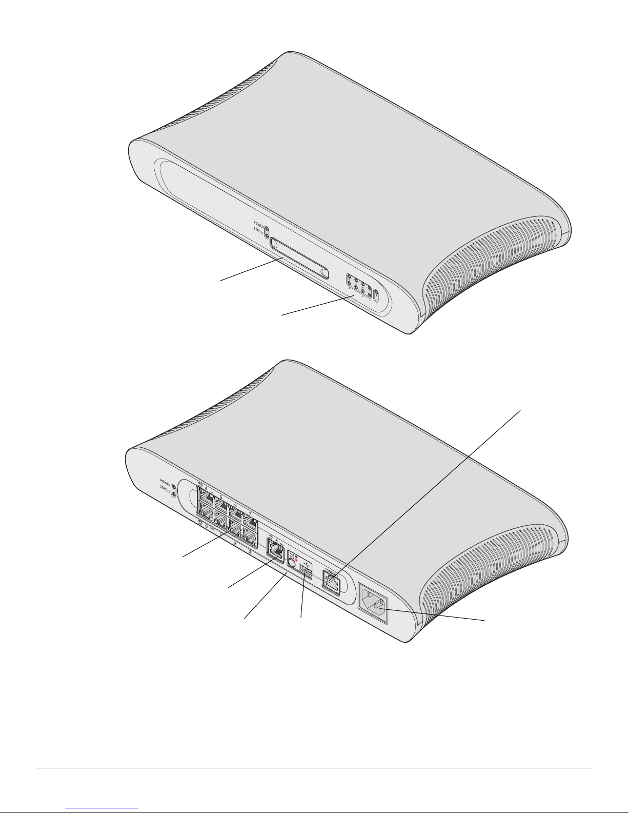
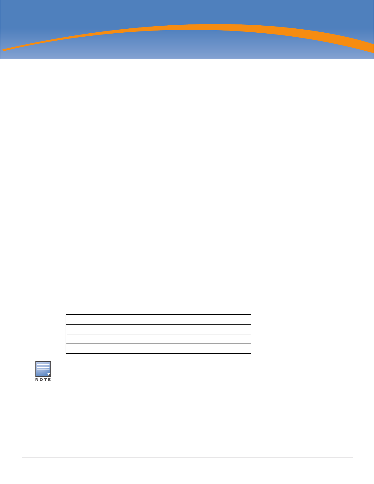
Figure 1 Aruba 620 Mobility Controller Front View
ExpressCard Slot
Port LEDs
Figure 2 Aruba 620 Mobility Controller Rear View
10/100Base-T
Ethernet Ports
10/100/1000Base-T
Gigabit Ethernet Port
Media Eject Button
USB port
Serial Console Port
AC Power Socket
The Aruba 620 is equipped with a media eject button, which allows users to eject storage devices safely and
place the system in standby. Pushing the media eject button changes the state of the Aruba 620; the table
below describes the states and LED behaviors associated with use of the media eject button:
10 | The Aruba 620 and 650 Mobility Controllers Aruba 620, 650 and Dell W-620, W-650 | FIPS 140-2 Level 2 Release Supplement

Table 2 Media Eject Button LED Behavior
Initial State LED State Action Status LED Function
NAS Media Operational Green-solid Press and hold
NAS Media Unmounted Amber-solid Press and hold
Operational Green-solid Press and hold
Operating with NAS
Media un-mounted
Standby Red-solid Press media eject
Amber-solid Press and hold
media eject button
for 1 to 5 seconds
only
media eject button
for 1 to 5 seconds
only
media eject button
for more than 5
seconds only
media eject button
for more than 5
seconds only
button
Amber-flashing Un-mount all NAS
media
Amber-flashing Mount all attached
NAS devices, and
return to fully
functional
operation
Red-flashing Controller goes
into Standby
Red-flashing Controller goes
into Standby
Amber-flashing Controller wake-up Green-solid
LED Action
Completed
Amber-solid
Green-solid
Red-solid
Red-solid
In non-rack deployments, the Aruba 620 is placed with the front facing out. This allows the cables to be
hidden and creates a more aesthetically pleasing look. Therefore, a set of LEDs displaying link activity on
the ports is placed on the front side. Same LEDs also exist in back side too. For information about the
behavior of these LEDs, see table below.
Table 3 Aruba 620 LED Status Indicators
LED Label Function Indicator Status
Power POWER Input Power Status Indicator On (Solid Green) Power on
Off No Power
Status STATUS Module Status Indicator On (Solid Green) Device is operational
On (Solid Red) Device failed or is in Standby
On (Solid Amber) Device is loading software
Off No power
10/100/1000Base-T Port LNK/ACT Link/Activity Status Indicator On (Solid Green) Link has been established
On (Flashing Green) Port is transmitting or receiving
data
1000 Interface Speed On (Solid Green) 1000 Mbps
Aruba 620, 650 and Dell W-620, W-650 | FIPS 140-2 Level 2 Release Supplement The Aruba 620 and 650 Mobility Controllers | 11
Off No link on port
Off 10/100 Mbps

Table 3 Aruba 620 LED Status Indicators
LED Label Function Indicator Status
10/100Base-T Ports LINK/ACT Link/Activity Status Indicator On (Solid Green) Link has been established
On (Flashing Green) Port is transmitting or receiving
data
Off No link on port
PoE PoE Status Indicator On (Solid Green) PoE is being provided
On (Solid Amber) The attached device has
requested PoE, but PoE is not
being provided by the port
Off PoE is not being provided
100 Interface Speed On (Solid Green) 100 Mbps
Off 10 Mbps
Aruba 650 Chassis
The Aruba 650 Mobility Controller chassis is also 1U not-modular. The following diagrams (Figure 3 and
Figure 4) show the front and rear view of the chassis respectively. The Aruba 650 Mobility Controller
chassis contains:
1x Console (RS-232) RJ-45 port
2x Gigabit Ethernet (10/100/1000Base-T)
4x Gigabit Ethernet (10/100/1000Base-T) with PoE+
2x Gigabit Ethernet pluggable (1000Base-X SFP)
1x ExpressCard® port
4x USB 2.0 port
1x AC input voltage 100-240 V, Universal Input
12 | The Aruba 620 and 650 Mobility Controllers Aruba 620, 650 and Dell W-620, W-650 | FIPS 140-2 Level 2 Release Supplement
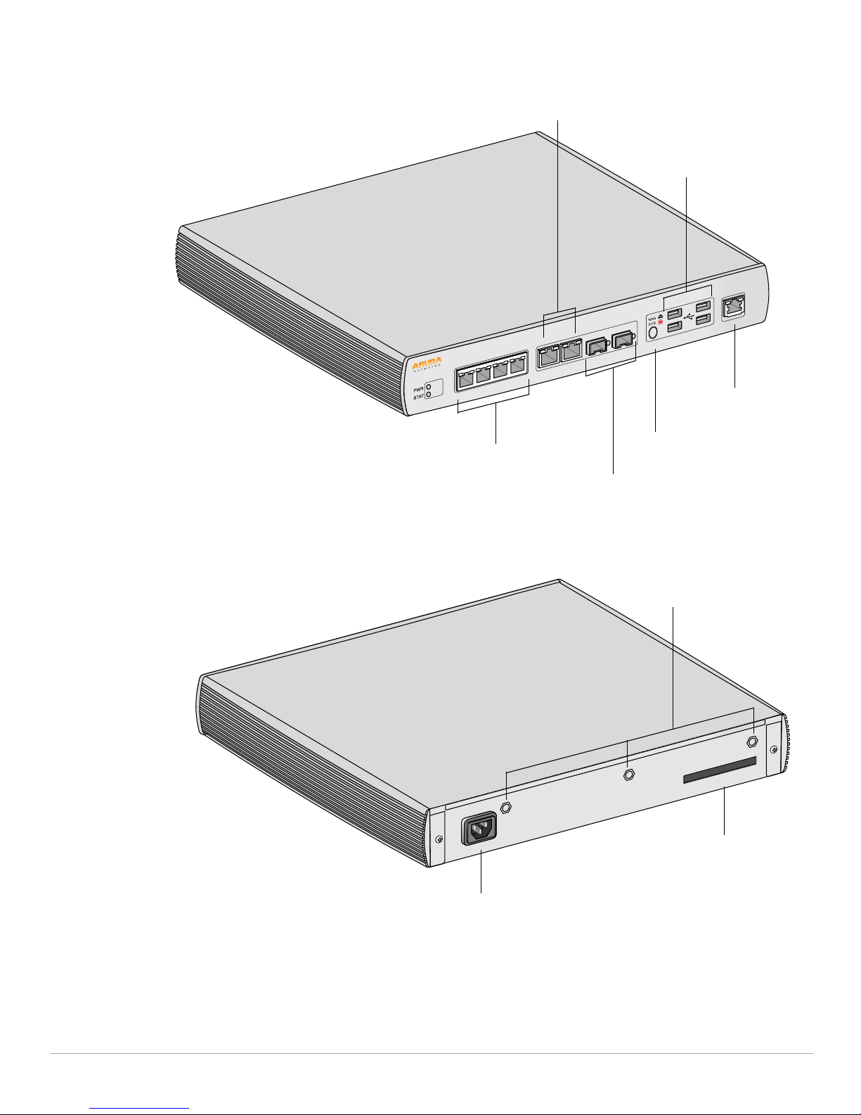
Figure 3 Aruba 650 Mobility Controller Front View
LINK/
ACT
10/100/1000Base-T
Gigabit Ethernet Ports
1000
LINK/
4 5 6 7
ACT
POE
0 1 2 3
LINK/
ACT
USB ports
LINK/
ACT
CONSOLE
Serial Console Port
10/100/1000Base-T Gigabit
Ethernet Ports with PoE
Figure 4 Aruba 650 Mobility Controller Rear View
Media Eject Button
1000Base-X (SFP) Ports
Antennae Interfaces
(651 Only)
Slot
ExpressCard Slot
The Aruba 650 Series is equipped with a media eject button, which allows users to eject storage devices
safely and place the system in standby. Pushing the media eject button changes the state of the Aruba 650
Aruba 620, 650 and Dell W-620, W-650 | FIPS 140-2 Level 2 Release Supplement The Aruba 620 and 650 Mobility Controllers | 13
AC Power Socket
 Loading...