

Dell 8200 Service Manual

Please check out our eBay auctions for more great
deals on Factory Service Manuals:

SECTION 1
Removing and Replacing Parts
Before You Begin
System Components
Hard Drive and Fixed Optical Drive
System Upgrades
Keyboard
Display
Microprocessor Thermal-Cooling Assembly
Microprocessor Module
Video Graphics Board
Palm Rest
Reserve Battery
System Board
Battery and Module Bay Latches
Battery Charger Board
LED Board

Fan
RJ-11/RJ-45 Module
www.dell.com | support.dell.com
2 Removing and Replacing Parts

SECTION 2
Before You Begin

Preparing to Work Inside the Computer
CAUTION: Only a certified service technician should perform
repairs on your computer. Damage due to servicing that is not
authorized by Dell is not covered by your warranty. Read and
follow applicable safety instructions in the
came with the computer.
CAUTION: Allow the computer to cool to room temperature before
working inside the computer.
NOTICE: To avoid damaging the computer, perform the following steps before
www.dell.com | support.dell.com
you begin working inside the computer.
1
Ensure that the work surface is flat and clean to prevent scratching the
Owner’s Manual
computer cover.
2 Save any work in progress and exit all open programs.
3 Turn off the computer and all attached devices.
that
HINT: Before
turning off the computer,
ensure that the computer
is not in a powermanagement mode.
Ensure that the computer is undocked.
4
5 Disconnect the computer from the electrical outlet.
6 To avoid possible damage to the system board, wait 10 to 20 seconds
and then disconnect any attached devices.
7 Disconnect all other external cables from the computer.
8 Remove any installed PC Cards or plastic blanks from the PC Card
slot.
9 Close the display and turn the computer upside down on a flat work
surface.
10 Remove the battery from the battery bay.
NOTICE: To avoid component damage, always remove any installed batteries
before you service the computer.
Remove any device installed in the module bay.
11
12 To dissipate static electricity while you work, periodically touch an
unpainted metal surface on the computer chassis.
13 Handle components and cards by their edges, and avoid touching pins
and contacts.
4 Before You Begin
Recommended Tools
The procedures in this document require the following tools:
• #1 magnetized Phillips screwdriver
• Small flat-blade screwdriver
• Microprocessor extractor
• Nonmarring plastic scribe
• Flash BIOS update program floppy disk or CD (provided when needed
to upgrade the BIOS)
Computer Orientation
back of computer
left right
front of computer
Before You Begin 5
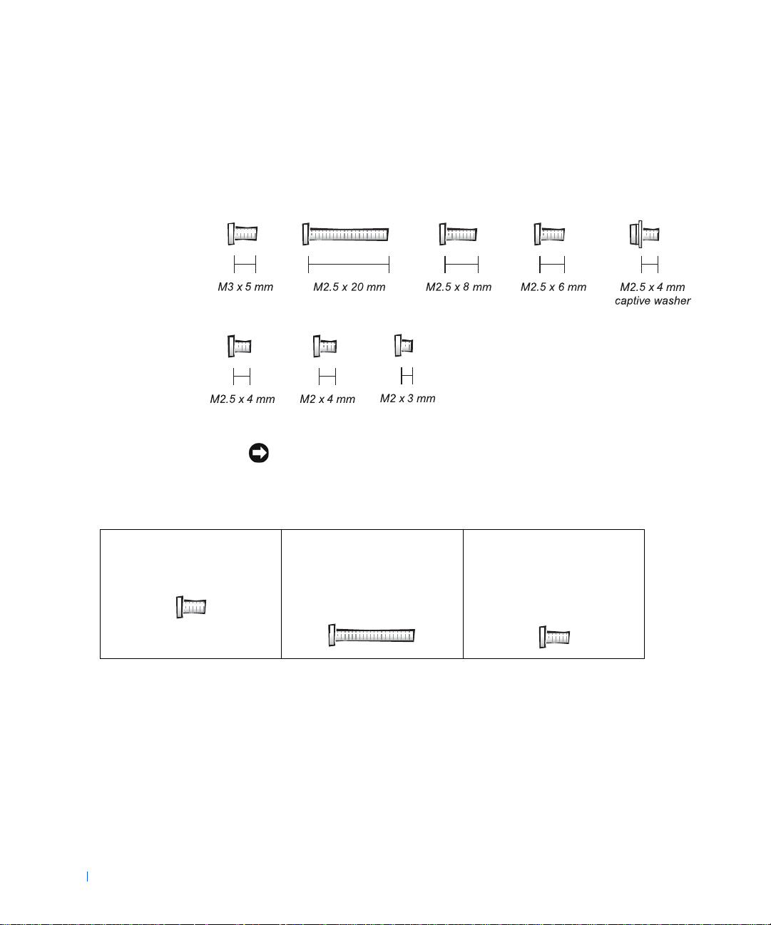
Screw Identification
When you are removing and replacing components, photocopy the
placemat as a tool to lay out and keep track of the component screws. The
placemat provides the number of screws and the sizes.
www.dell.com | support.dell.com
NOTICE: When reinstalling a screw, you must use a screw of the correct
diameter and length. Ensure that the screw is properly aligned with its
corresponding hole, and avoid overtightening.
Hard-Drive Door Security:
M3 x 5 mm (1 each)
6 Before You Begin
Keyboard to Bottom Case:
M2.5 x 20 mm (4 each; one in
memory door and one in Mini
PCI door)
Display to Bottom Case:
M2.5 x 6 mm (3 each; 2 at back
of computer; 1 at display flexcable strain relief)
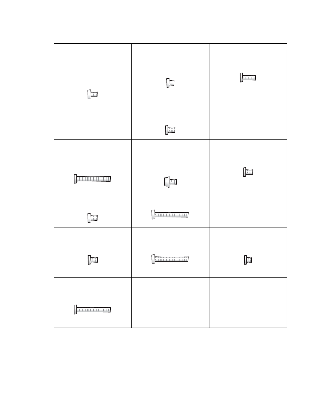
Display Bezel:
Rubber screw covers (4 each)
Plastic screw covers (2 each)
M2.5 x 4 mm (6 each)
Display Panel to Display
Mounting Bracket:
M2 x 3 mm (6 each)
Flex-Cable Mounting Bracket to
Top C o ve r :
M2.5 x 4 mm (1 each)
Video Graphics Board:
M2.5 x 8 (3 each)
Pal m Rest to
Bottom Case:
M2.5 x 20 mm (9 each)
Pal m Rest B r a c ket:
M2.5 x 4 mm (4 each)
Fan:
M2 x 4 mm (3 each)
Mini PCI Card:
M2.5 x 20 mm (1 each)
System Board:
M2.5 x 4 mm captive washer
(3 each)
M2.5 x 20 mm (1 each)
Memory Module/Modem Cover:
M2.5 x 20 mm (1 each)
LED Board:
M2 x 4 mm (2 each)
Modem Daughter Card:
M2 x 3 mm (1 each)
Before You Begin 7

www.dell.com | support.dell.com
8 Before You Begin

SECTION 3
System Components
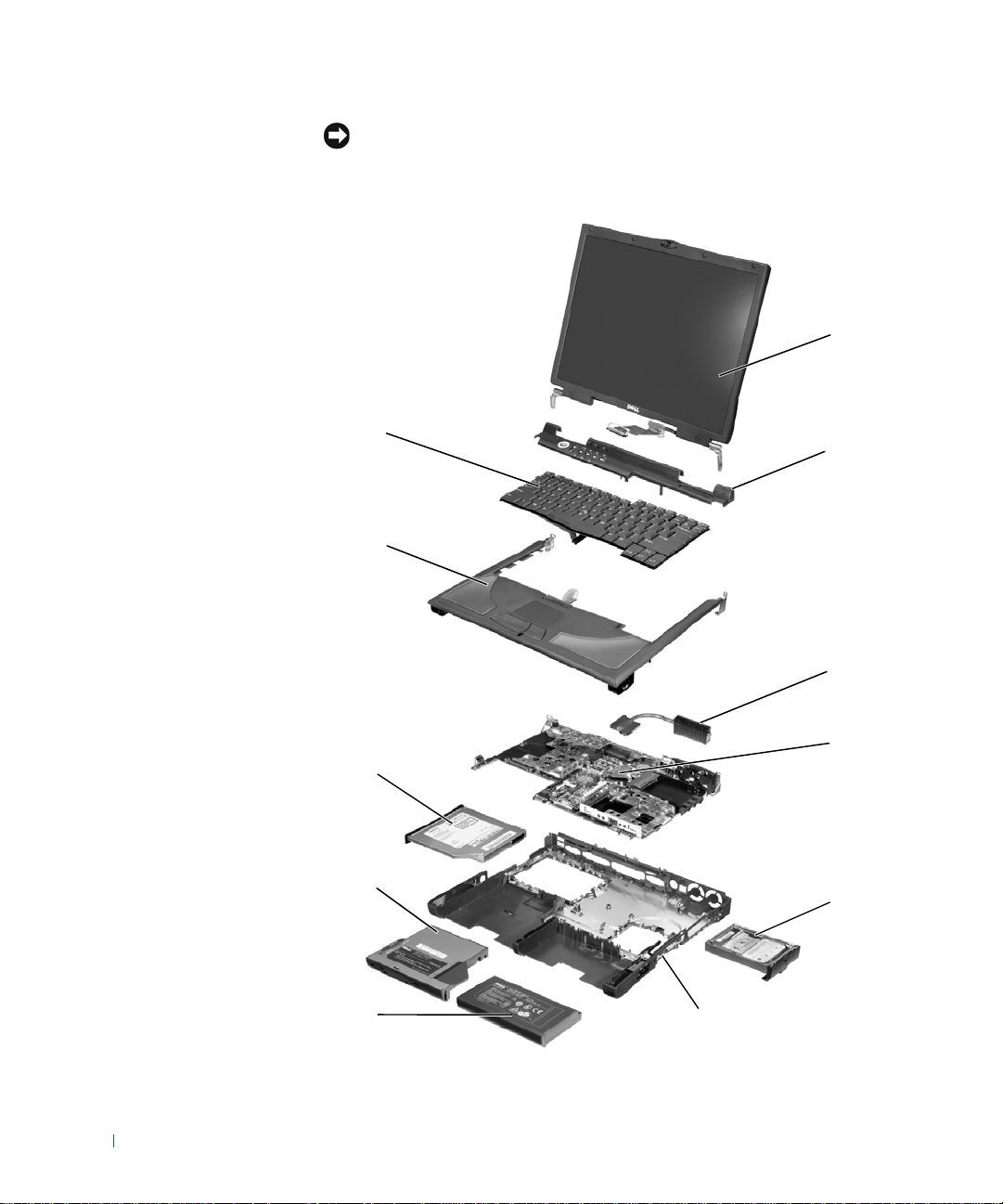
NOTICE: Unless otherwise noted, each procedure in this document assumes
that a part can be replaced by performing the removal procedure in reverse
order.
1
www.dell.com | support.dell.com
11
2
10
3
10 System Components
4
9
8
5
76

1 display assembly 7 main battery
2 hinge cover 8 device in module bay
3 microprocessor thermal-
cooling assembly
4 system board 10 palm rest
5 hard drive 11 keyboard
6 bottom case
9 fixed optical drive
System Components 11

www.dell.com | support.dell.com
12 System Components

SECTION 4
Hard Drive and Fixed Optical Drive
NOTICE: Only a certified service technician should perform repairs on your
computer. Damage due to servicing that is not authorized by Dell is not covered
by your warranty.
Hard Drive
NOTICE: Disconnect the computer and attached devices from the electrical
outlet and remove any installed batteries.
NOTICE: To avoid ESD, ground yourself by using a wrist grounding strap or
by periodically touching unpainted metal on the computer.
NOTICE: The hard drive is very sensitive to shock. Handle the drive by its
www.dell.com | support.dell.com
edges (do not squeeze the top of the case), and avoid dropping it.
1
14 Hard Drive and Fixed Optical Drive
2
3
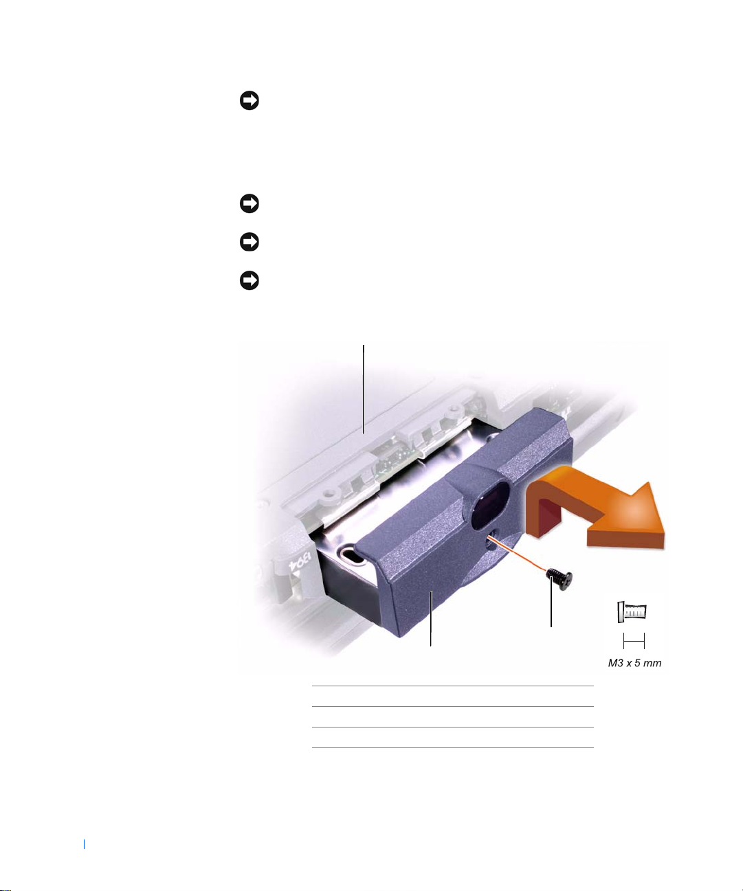
1 bottom of computer
2 M3 x 5-mm screw
3 hard drive door
Removing the Hard Drive
1 Follow the instructions in "Preparing to Work Inside the Computer."
2 Remove the M3 x 5-mm screw.
3 Pull the hard drive out.
Replacing the Hard Drive
1 Push the hard drive into the drive bay until the drive door is flush with
the computer case.
2 Push down on the drive until it snaps into place.
3 Replace the M3 x 5-mm screw in the hard drive door.
Fixed Optical Drive
NOTICE: Disconnect the computer and attached devices from the electrical
outlet and remove any installed batteries.
NOTICE: To avoid ESD, ground yourself by using a wrist grounding strap or
by periodically touching unpainted metal on the computer.
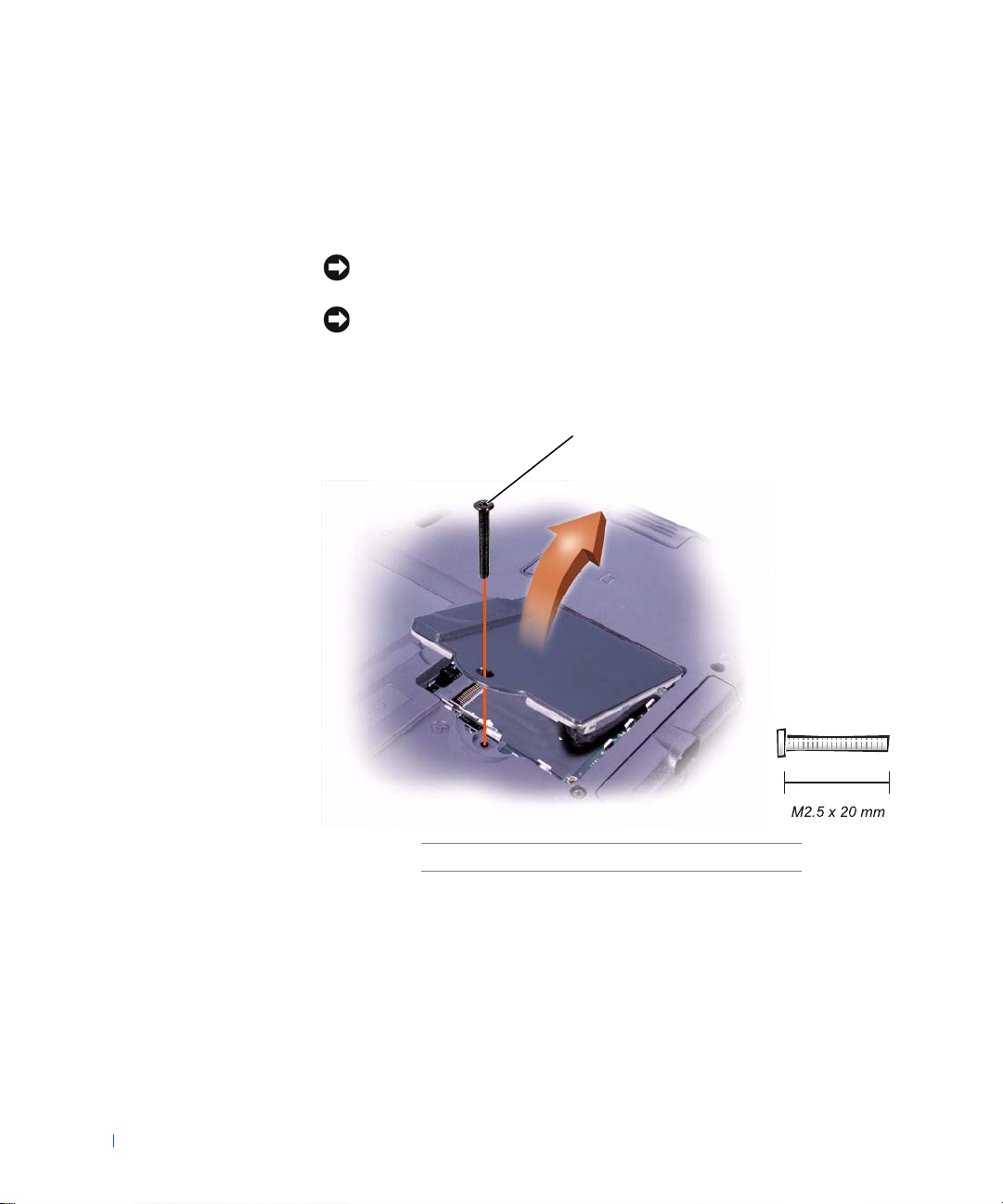
1
2
Hard Drive and Fixed Optical Drive 15

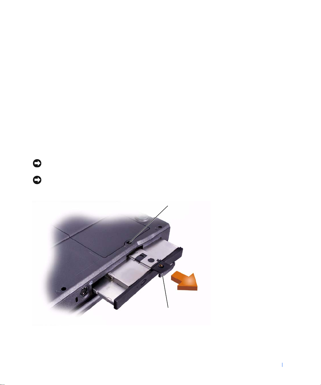
1 captive screw
2 pull tab
Removing the Fixed Optical Drive
1 Follow the instructions in "Preparing to Work Inside the Computer."
2 Loosen the captive screw on the bottom of the computer.
3 Turn the computer over (to keep the captive screw from interfering
with the pull tab) and pull out the pull tab.
www.dell.com | support.dell.com
4 Use the pull tab to remove the fixed optical drive.
16 Hard Drive and Fixed Optical Drive

SECTION 5
System Upgrades
Memory Modules
NOTICE: Disconnect the computer and any attached devices from electrical
outlets and remove any installed batteries.
NOTICE: To avoid ESD, ground yourself by using a wrist grounding strap or
by periodically touching unpainted metal on the computer.
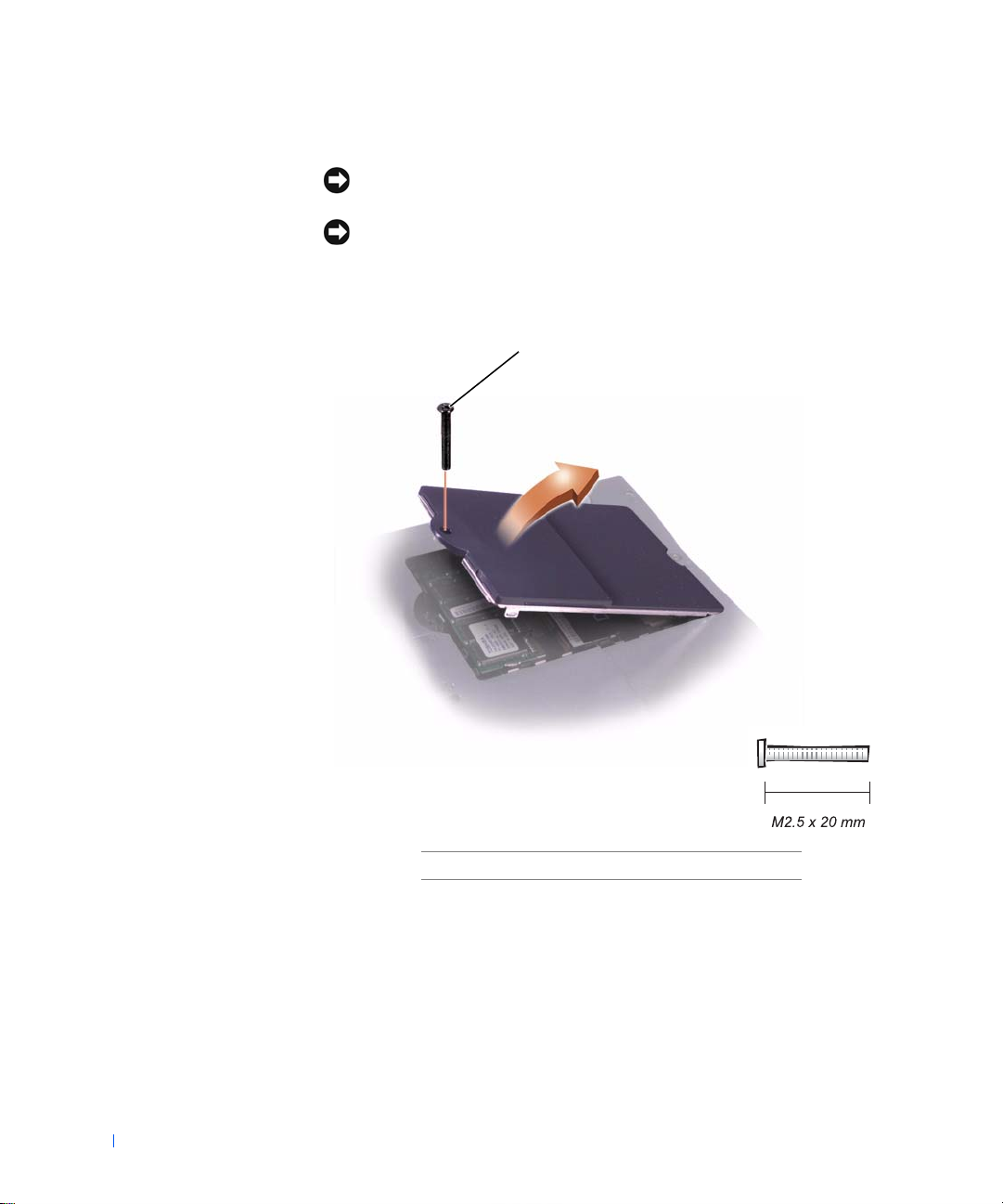
Removing the Memory Module/Modem Cover
1
www.dell.com | support.dell.com
18 System Upgrades
1 M2.5 x 20-mm screw
1 Follow the instructions in "Preparing to Work Inside the Computer."
2 Remove the M2.5 x 20-mm screw from the memory module/modem
cover.
3 Disengage the metal tabs at the opposite end of the cover.
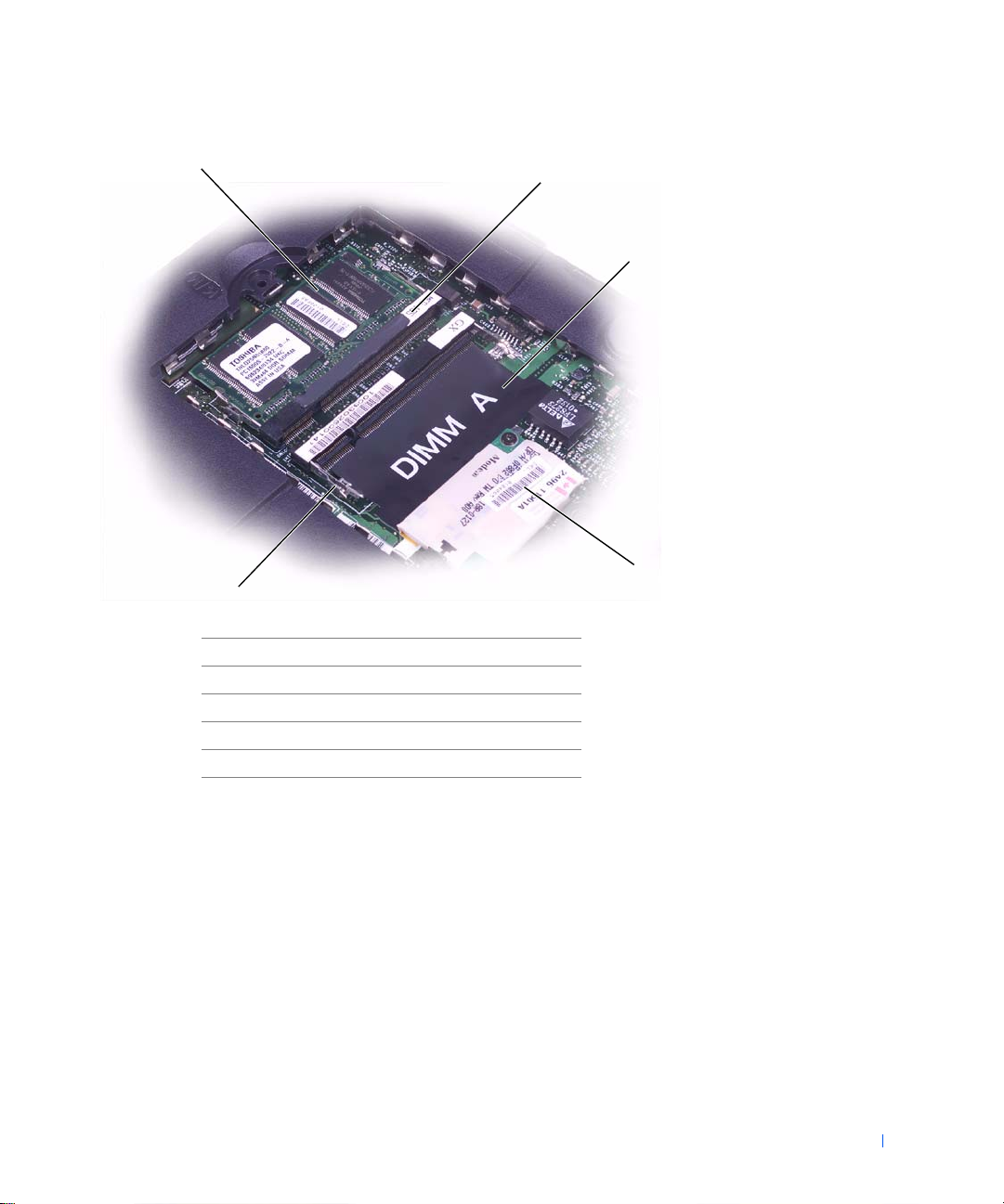
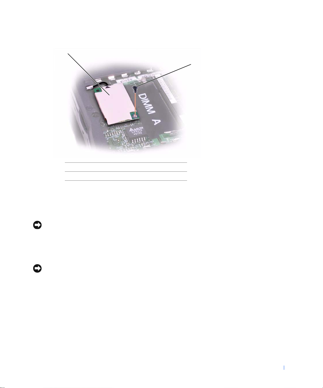
1
5
1 DIMM B
2 memory module sockets (2)
3 DIMM A socket
4 modem daughter card
5 metal tabs (2 per socket)
2
3
4
Removing the Memory Modules
1 Remove the memory module/modem cover.
2 To release a memory module from its socket, spread apart the tabs at
each side of the module until the module pops up slightly.
3 Lift the memory module out of its socket.
System Upgrades 19

Replacing the Memory Modules
1 If you only have one memory module, install it in the socket labeled
"DIMM A." Install a second memory module in the socket labeled
"DIMM B."
HINT: Memory
modules are keyed to fit
into their sockets in only
one direction.
2 Insert the memory-module edge connector into the socket slot at a
45-degree angle and press the module firmly into the slot.
3 Pivot the module down until it clicks into place. If you do not hear a
click, remove the module and reinstall it.
4 Insert the metal tabs on the memory module/modem cover into the
bottom case, rotate the cover down, and replace the M2.5 x 20-mm
www.dell.com | support.dell.com
screw.
Modem Daughter Card
Removing the Modem Daughter Card
NOTICE: Disconnect the computer and any attached devices from electrical
outlets and remove any installed batteries.
NOTICE: To avoid ESD, ground yourself by using a wrist grounding strap or
by periodically touching unpainted metal on the computer.
1
Follow the instructions in "Preparing to Work Inside the Computer."
2 Turn the computer over and remove the memory module/modem
cover.
20 System Upgrades
1
2
1 modem daughter card
2 M2 x 3-mm screw
3 Remove the M2 x 3-mm screw that secures the modem daughter card
to the system board.
4 Use the pull tab to pull the modem daughter card straight up out of its
connector.
NOTICE: Do not pull on the modem cable. Pull the connector on the end of
the cable to disconnect the cable.
Disconnect the modem cable from the modem daughter card.
5
Replacing the Modem Daughter Card
NOTICE: The cable connectors are keyed for correct insertion. Do not force
the connections.
Connect the modem cable to the modem daughter card.
1
2 Use the screw and boss holes at opposite corners of the modem
daughter card to align the card, and press the card into its connector
on the system board.
3 Install the M2 x 3-mm screw that secures the card to the system board.
4 Replace the memory module/modem cover.
System Upgrades 21
Mini PCI Card
You must remove the optional Mini PCI wireless modem (if installed)
before the system board can be removed. A wireless modem card must be
connected to the internal antenna of the computer.
NOTICE: Disconnect the computer and attached devices from electrical
outlets and remove any installed batteries.
NOTICE: To avoid ESD, ground yourself by using a wrist grounding strap or
by periodically touching unpainted metal on the computer.
Mini PCI Card Cover
www.dell.com | support.dell.com
1
22 System Upgrades
1 M2.5 x 20-mm screw
Removing the Mini PCI Card
1 Follow the instructions in "Preparing to Work Inside the Computer."
2 Remove the M2.5 x 20-mm screw and then remove the Mini PCI card
cover.
3 To release the Mini PCI card, spread the metal securing tabs until the
card pops up slightly.
4 Disconnect the card from the internal antenna.
5 Lift out the card and disconnect any attached cables.
Replacing the Mini PCI Card
1 Align the Mini PCI card with the socket at a 45-degree angle, and press
the Mini PCI card into the socket.
2 Connect the internal-antenna cable to the primary-antenna connector
on the card.
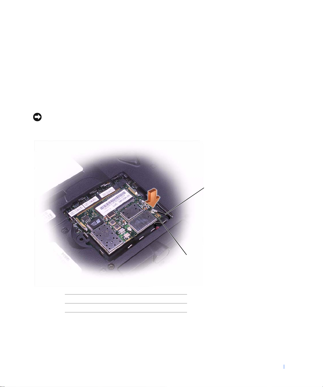
NOTICE: The connectors are keyed for correct insertion; do not force the
connections.
1
2
1 internal-antenna cable
2 primary-antenna connector on card
Pivot the Mini PCI card down until it clicks into place.
3
4 Replace the Mini PCI card cover and the M2.5 x 20-mm screw.
System Upgrades 23

www.dell.com | support.dell.com
24 System Upgrades

SECTION 6
Keyboard
 Loading...