

Page 1

dell.com/regulatory_compliance
Dell™ OptiPlex™ 780-USFF Mounting Bracket
User’s Guide
Under Desk MountWall with Wood Stud Mount
The Dell OptiPlex 780-USFF Mounting Bracket supports the System
in vertical or horizontal orientations.
www.dell.com support.dell.com
1 of 14
Page 2
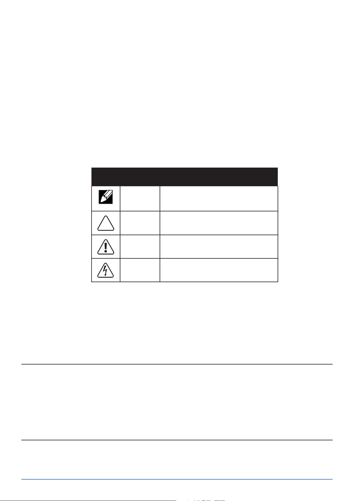
Hazard Symbols Review
These symbols alert the user about a safety condition that demands attention. All users of the
product should be able to recognize and understand the signi cance of the following safety
hazards if encountered on the product or within product documentation.
Symbol Signal Word Level of Hazard
NOTE
CAUTION
WARNING
ELECTRICAL
A NOTE indicates important information that helps you
make better use of your Dell Mounting Bracket.
A CAUTION indicates either potential damage to
hardware or loss of data and tells you how to avoid the
problem.
A WARNING indicates either potential for property
damage, personal injury, or death.
An ELECTRICAL indicates an impending electrical hazard
which, if not avoided, may result in personal injury, re
and/or death.
Information in this document is subject to change without notice.
© 2009 Dell Inc. All rights reserved. Printed in China.
Reproduction of these materials in any manner whatsoever without the written permission of Dell Inc. is strictly forbidden.
Trademarks used in this text: and the logo are trademarks of Dell Inc.
Other trademarks and trade names may be used in this document to refer to either the entities claiming the marks and names or their products. Dell Inc. disclaims
any proprietary interest in trademarks and trade names other than its own.
Model ARWAL
October 2009 Rev. A00
2 of 14
2 of 14
Page 3

Contents
1 About your Dell OptiPlex 780-USFF Mounting Bracket ...................................................4
2 Setting up your Dell OptiPlex 780-USFF Mounting Bracket ............................................. 4
3 Speci cations ...............................................................................................................14
4 Finding Information ..................................................................................................... 14
3 of 14
Page 4

About your Dell OptiPlex 780-USFF Mounting Bracket
Under Desk MountWall Mount
1
1
2
1
3
1 System Mounting Bracket
2 System Sleeve
3 System Chassis (ordered separately)
2
3
Setting up the Dell OptiPlex 780-USFF Mounting Bracket
Components
Mounting Bracket, System Sleeve, two Lag Screws
WARNING: Because surfaces
vary widely and the ultimate
mounting method is out of
DELL’s control, it is imperative
that you consult with an appropriate engineering, architectural
or construction professional to
2x
M8 x 80 mm
ensure that your DELL mounting solution can support 50 lbs
(23 kg) and is mounted properly.
2
4 of 14
NOTE: Refer to the System Instruction Guides, packaged separately.
Page 5

1 Ensure the system sleeve is unlocked, (orange tab will show).
2 Extend the system label carrier.
5 of 14
Page 6

3 Insert the system into the system sleeve in the orientation appropriate
to the mounting method as illustrated below.
CAUTION: Do not reverse the insertion order. The
system must be inserted in the orientation speci ed
to ensure proper functioning of the CD tray!
Wood Stud Wall Mount
Insert the system into the system sleeve
with the connections end rst.
Under Desk Mount
Insert the system into the system
sleeve with the CD end rst.
6 of 14
NOTE: When inserted properly for
wall mount applications, the connections end of the system will not
reach the
edge of
the system
sleeve.
NOTE: When inserted properly for
under desk mount applications, the
CD end of
the system
will reach
the end of
the system
sleeve.
Page 7

4 Push the system label carrier into the system sleeve, then slide the switch to lock.
Wall
Mount
Under Desk
Mount
5 Determine the mounting method (Wall or Under Desk), then follow
the appropriate instructions on the pages noted below.
Wood Stud Wall Mount
CAUTION: The provided fasteners are
rated for use with 2 x 4 wood studs,
minimum. Consult an engineering professional to determine which fasteners are
appropriate based on surface material
and applied load.
Under Desk Mount
≥ 1/2”
(1.25 cm)
4x
CAUTION: Mounting fasteners are not
included with bracket. Use appropriate
fasteners to attach to a solid mounting
surface that can support 50 lbs. (23 kg). At a
minimum, the mounting surface should be
1/2” (1.25 cm) thick wood and mount using
4 metal wood screws (M4 x 12mm).
≥ M4 x 12mm
Wall Mount
Steps
Under Desk
Mount Steps
128
7 of 14
Page 8

Wood Stud Wall Mount Steps
6 Attach the mounting bracket to the wood stud.
NOTE: The following tools are required for installation to the
wall stud: stud nder, measuring tape, pencil, level, safety
glasses, power drill with 3/16” (5mm bit suitable for wood).
Stud Finder
Ø 5 mm (3/16”)
2
1
Wall Mount Clearance Front View
≥2.45” (62.2 mm)
Left Wall
Ceiling
≥3.33” (85 mm)
≥2.28” (58 mm)
Right Wall
Wall Mount Clearance Back View
Right Wall
Ceiling
≥6.0” (152.4 mm)
≥8.0” (203.2 mm)≥13” (330.2 mm)
Left Wall
8 of 14
Page 9

a
Stud Finder
de
Ø 5 mm (3/16”)
b
c
M8 x 80 mm
2x
CAUTION: Make sure the wall mount bracket is
level, ush and snuggly tted to the wall surface.
f
Lower the system onto the
wall-mounted bracket.
9 of 14
Page 10

To remove the system from the mounting bracket:
a Push the quick release tab backward.
b Lift the system upward until it is free of the bracket.
ab
Under Desk Mount Steps
6 Mark the mounting hole locations using the measurements
provided on the next pages.
NOTE: The following tools are required for installation to the desk:
measuring tape, pencil, level.
2
1
10 of 14
Page 11

Under Desk Clearance during assembly
≥6.0” (152.4 mm)
≥6.0” (152.4 mm)
≤4.25” (108 mm)
Wall / Desk
Wall / Desk
≤ .5” (12.7 mm)
Edge of Desk
Under Desk Clearance after assembly
Wall / Desk
≥6.0” (152.4 mm)
≥6.0” (152.4 mm)
≤4.25” (108 mm)
≤ .5” (12.7 mm)
≤
Wall / Desk
Edge of Desk
11 of 14
Page 12

Under Desk Clearance
CAUTION: The system should have at least 6” (152.4 mm) of clearance on all
vented sides to permit the air ow required for proper ventilation. Restricting
air ow can damage the equipment or cause overheating.
Wall / Desk
≥6.0” (152.4 mm)
a Mount the bracket underneath the desk.
CAUTION: Mounting fasteners are not
included with bracket. Use appropriate
fasteners to attach to a solid mounting
surface that can support 50 lbs. (23 kg).
At a minimum, the mounting surface
should be 1/2” (1.25 cm) thick wood and
mount using 4 metal wood screws
(M4 x 12mm).
Wall / Desk
≥6.0” (152.4 mm)
≤4.25” (108 mm)
Edge of Desk
≥ 1/2”
(1.25 cm)
CAUTION: Make sure the wall mount bracket is
level, ush and snuggly tted to the wall surface.
4x
≥ M4 x 12mm
b Slide the system into place on the desk-mounted bracket.
12 of 14
Page 13

To remove the system from the mounting bracket:
a Push the quick release tab upward.
b Slide the system toward the right until it is free of the bracket.
a
b
13 of 14
Page 14

Speci cations
System Weight Capacity
Dell System: OptiPlex 780-USFF ≤ 7 lbs (3.2 kg)
Temperature
Operating 32°F to 95°F (0°C to 35°C )
Storage -40°F to 149°F (-40°C to +69°C)
Transportation -40°F to 149°F (-40°C to +69°C)
3
Finding Information
If you need to: See:
Find safety best practices information for your computer,
review Warranty information, Terms and Conditions (U.S.
only), Safety instructions, Regulatory information,
Ergonomics information, and End User Agreement
The safety and regulatory documents that
shipped with your computer and the
Regulatory Compliance Homepage at
www.dell.com/regulatory_compliance.
4
14 of 14
 Loading...