

Page 1

53-1002116-01
07 December 2010
Dell Converged Enhanced
Ethernet
Administrator’s Guide
Page 2

Information in this document is subject to change without notice.
© 2010 Dell Inc. All rights reserved.
Reproduction of these materials in any manner whatsoever without the written permission of Dell Inc. is strictly forbidden.
Trademarks used in this text: Dell, the DELL logo, Inspiron, Dell Precision, Dimension, OptiPlex, Latitude, PowerEdge, PowerVault,
PowerApp, and Dell OpenManage are trademarks of Dell Inc.; Intel, Pentium, and Celeron are registered trademarks of Intel
Corporation in the U.S. and other countries; Microsoft, Windows, Windows Server, MS-DOS and Windows Vista are either
trademarks or registered trademarks of Microsoft Corporation in the United States and/or other countries.
Other trademarks and trade names may be used in this document to refer to either the entities claiming the marks and names or
their products. Dell Inc. disclaims any proprietary interest in trademarks and trade names other than its own.
Regulatory Model Code: M8428-k
Page 3

Contents
About This Document
In this chapter . . . . . . . . . . . . . . . . . . . . . . . . . . . . . . . . . . . . . . . . . . . xv
How this document is organized . . . . . . . . . . . . . . . . . . . . . . . . . . . . xv
Supported hardware and software . . . . . . . . . . . . . . . . . . . . . . . . . . xvi
Document conventions. . . . . . . . . . . . . . . . . . . . . . . . . . . . . . . . . . . . xvi
Text formatting . . . . . . . . . . . . . . . . . . . . . . . . . . . . . . . . . . . . . . . xvi
Command syntax conventions . . . . . . . . . . . . . . . . . . . . . . . . . xvii
Notes, cautions, and warnings . . . . . . . . . . . . . . . . . . . . . . . . . xvii
Notice to the reader . . . . . . . . . . . . . . . . . . . . . . . . . . . . . . . . . . . . . xviii
Getting technical help. . . . . . . . . . . . . . . . . . . . . . . . . . . . . . . . . . . . xviii
Contacting Dell. . . . . . . . . . . . . . . . . . . . . . . . . . . . . . . . . . . . . . xviii
Chapter 1 Introducing FCoE
In this chapter . . . . . . . . . . . . . . . . . . . . . . . . . . . . . . . . . . . . . . . . . . . . 1
FCoE terminology . . . . . . . . . . . . . . . . . . . . . . . . . . . . . . . . . . . . . . . . . 1
FCoE overview . . . . . . . . . . . . . . . . . . . . . . . . . . . . . . . . . . . . . . . . . . . . 1
FCoE hardware. . . . . . . . . . . . . . . . . . . . . . . . . . . . . . . . . . . . . . . . 2
Layer 2 Ethernet overview . . . . . . . . . . . . . . . . . . . . . . . . . . . . . . . . . . 3
Layer 2 forwarding . . . . . . . . . . . . . . . . . . . . . . . . . . . . . . . . . . . . . 3
VLAN tagging . . . . . . . . . . . . . . . . . . . . . . . . . . . . . . . . . . . . . . . . . 4
Loop-free network environment . . . . . . . . . . . . . . . . . . . . . . . . . . 5
Frame classification (incoming) . . . . . . . . . . . . . . . . . . . . . . . . . . 5
Congestion control and queuing. . . . . . . . . . . . . . . . . . . . . . . . . . 6
Access control . . . . . . . . . . . . . . . . . . . . . . . . . . . . . . . . . . . . . . . . 7
Access Gateway . . . . . . . . . . . . . . . . . . . . . . . . . . . . . . . . . . . . . . . 7
Trunking . . . . . . . . . . . . . . . . . . . . . . . . . . . . . . . . . . . . . . . . . . . . . 8
Flow Control . . . . . . . . . . . . . . . . . . . . . . . . . . . . . . . . . . . . . . . . . . 8
FCoE Initialization Protocol . . . . . . . . . . . . . . . . . . . . . . . . . . . . . . . . . 8
FIP discovery . . . . . . . . . . . . . . . . . . . . . . . . . . . . . . . . . . . . . . . . . 8
FIP login . . . . . . . . . . . . . . . . . . . . . . . . . . . . . . . . . . . . . . . . . . . . . 9
FIP logout . . . . . . . . . . . . . . . . . . . . . . . . . . . . . . . . . . . . . . . . . . .10
FCoE login. . . . . . . . . . . . . . . . . . . . . . . . . . . . . . . . . . . . . . . . . . .10
FCoE logout . . . . . . . . . . . . . . . . . . . . . . . . . . . . . . . . . . . . . . . . . 10
Logincfg . . . . . . . . . . . . . . . . . . . . . . . . . . . . . . . . . . . . . . . . . . . .11
Name server. . . . . . . . . . . . . . . . . . . . . . . . . . . . . . . . . . . . . . . . . 11
FC zoning . . . . . . . . . . . . . . . . . . . . . . . . . . . . . . . . . . . . . . . . . . .11
Registered State Change Notification (RSCN) . . . . . . . . . . . . . .12
FCoE queuing . . . . . . . . . . . . . . . . . . . . . . . . . . . . . . . . . . . . . . . . . . .12
Dell Converged Enhanced Ethernet Administrator’s Guide iii
53-1002116-01
Page 4

Chapter 2 Using the CEE CLI
In this chapter . . . . . . . . . . . . . . . . . . . . . . . . . . . . . . . . . . . . . . . . . . .13
Management Tools . . . . . . . . . . . . . . . . . . . . . . . . . . . . . . . . . . . . . . .13
CEE Command Line Interface . . . . . . . . . . . . . . . . . . . . . . . . . . . . . . 13
Saving your configuration changes. . . . . . . . . . . . . . . . . . . . . . . 14
CEE CLI RBAC permissions . . . . . . . . . . . . . . . . . . . . . . . . . . . . . 14
Accessing the CEE CLI through the console or Telnet . . . . . . . 15
Accessing the CEE CLI from the Fabric OS shell . . . . . . . . . . . .15
CEE CLI command modes . . . . . . . . . . . . . . . . . . . . . . . . . . . . . . 15
CEE CLI keyboard shortcuts . . . . . . . . . . . . . . . . . . . . . . . . . . . . 17
Using the do command as a shortcut . . . . . . . . . . . . . . . . . . . .18
Displaying CEE CLI commands and command syntax . . . . . . . 18
CEE CLI command completion . . . . . . . . . . . . . . . . . . . . . . . . . .19
CEE CLI command output modifiers. . . . . . . . . . . . . . . . . . . . . .19
Internal and external 10 Gbps Ethernet interfaces syntax . . . . . . .20
Chapter 3 Initial FCoE and CEE Configuration
In this chapter . . . . . . . . . . . . . . . . . . . . . . . . . . . . . . . . . . . . . . . . . . .21
Overview . . . . . . . . . . . . . . . . . . . . . . . . . . . . . . . . . . . . . . . . . . . . . . .21
Configuring the FCoE interfaces . . . . . . . . . . . . . . . . . . . . . . . . . . . .21
Configuring FCoE VLAN . . . . . . . . . . . . . . . . . . . . . . . . . . . . . . . . 22
Assigning FCoE map on to an interface . . . . . . . . . . . . . . . . . . . 23
Configuring the CEE interfaces . . . . . . . . . . . . . . . . . . . . . . . . . . . . .23
Configuring DCBX . . . . . . . . . . . . . . . . . . . . . . . . . . . . . . . . . . . . . . . .24
Configuring Spanning Tree Protocol. . . . . . . . . . . . . . . . . . . . . . . . . .25
Configuring VLAN membership . . . . . . . . . . . . . . . . . . . . . . . . . . . . . 25
Configuring protect mode. . . . . . . . . . . . . . . . . . . . . . . . . . . . . . . . . .26
Chapter 4 Configuring IP static routes
In this chapter . . . . . . . . . . . . . . . . . . . . . . . . . . . . . . . . . . . . . . . . . . . 27
IP static routes overview . . . . . . . . . . . . . . . . . . . . . . . . . . . . . . . . . . .27
Configuring IP static routes . . . . . . . . . . . . . . . . . . . . . . . . . . . . . . . .28
Recursive IP static routes . . . . . . . . . . . . . . . . . . . . . . . . . . . . . .29
Floating IP static routes. . . . . . . . . . . . . . . . . . . . . . . . . . . . . . . . 29
Displaying and clearing IP static routes . . . . . . . . . . . . . . . . . . .29
Chapter 5 Configuring VLANs Using the CEE CLI
In this chapter . . . . . . . . . . . . . . . . . . . . . . . . . . . . . . . . . . . . . . . . . . . 31
VLAN overview . . . . . . . . . . . . . . . . . . . . . . . . . . . . . . . . . . . . . . . . . . . 31
Ingress VLAN filtering . . . . . . . . . . . . . . . . . . . . . . . . . . . . . . . . . . . . . 31
VLAN configuration guidelines and restrictions . . . . . . . . . . . . . . . .33
Default VLAN configuration . . . . . . . . . . . . . . . . . . . . . . . . . . . . . . . .33
iv Dell Converged Enhanced Ethernet Administrator’s Guide
53-1002116-01
Page 5

VLAN configuration and management. . . . . . . . . . . . . . . . . . . . . . . . 34
Enabling and disabling an interface port . . . . . . . . . . . . . . . . . .34
Configuring the MTU on an interface port . . . . . . . . . . . . . . . . .34
Creating a VLAN interface . . . . . . . . . . . . . . . . . . . . . . . . . . . . . .35
Enabling STP on a VLAN . . . . . . . . . . . . . . . . . . . . . . . . . . . . . . . 35
Disabling STP on a VLAN . . . . . . . . . . . . . . . . . . . . . . . . . . . . . . .35
Configuring a VLAN interface to forward FCoE traffic . . . . . . . .36
Configuring an interface port as a Layer 2 switch port . . . . . . .36
Configuring an interface port as an access interface . . . . . . . .36
Configuring an interface port as a trunk interface . . . . . . . . . .37
Disabling a VLAN on a trunk interface . . . . . . . . . . . . . . . . . . . . 37
Configuring an interface port as a converged interface . . . . . . 37
Disabling a VLAN on a converged interface . . . . . . . . . . . . . . . .38
Configuring protocol-based VLAN classifier rules . . . . . . . . . . . . . . .38
Configuring a VLAN classifier rule. . . . . . . . . . . . . . . . . . . . . . . .39
Configuring MAC address-based VLAN classifier rules . . . . . . .39
Deleting a VLAN classifier rule . . . . . . . . . . . . . . . . . . . . . . . . . .39
Creating a VLAN classifier group and adding rules . . . . . . . . . .39
Activating a VLAN classifier group with an interface port . . . . .40
Clearing VLAN counter statistics. . . . . . . . . . . . . . . . . . . . . . . . .40
Displaying VLAN information. . . . . . . . . . . . . . . . . . . . . . . . . . . .40
Configuring the MAC address table . . . . . . . . . . . . . . . . . . . . . . . . . .40
Specifying or disabling the aging time for MAC addresses. . . . 41
Adding static addresses to the MAC address table. . . . . . . . . . 41
Chapter 6 Configuring STP, RSTP, and MSTP using the CEE CLI
In this chapter . . . . . . . . . . . . . . . . . . . . . . . . . . . . . . . . . . . . . . . . . . .43
STP overview . . . . . . . . . . . . . . . . . . . . . . . . . . . . . . . . . . . . . . . . . . . .43
Configuring STP on Dell FCoE hardware. . . . . . . . . . . . . . . . . . .44
RSTP overview. . . . . . . . . . . . . . . . . . . . . . . . . . . . . . . . . . . . . . . . . . . 45
MSTP overview . . . . . . . . . . . . . . . . . . . . . . . . . . . . . . . . . . . . . . . . . . 47
Configuring MSTP on Dell FCoE hardware . . . . . . . . . . . . . . . . .48
STP, RSTP, and MSTP configuration guidelines and restrictions . . .49
Default STP, RSTP, and MSTP configuration . . . . . . . . . . . . . . . . . . .50
Dell Converged Enhanced Ethernet Administrator’s Guide v
53-1002116-01
Page 6

STP, RSTP, and MSTP configuration and management . . . . . . . . . . 51
Enabling STP, RSTP, or MSTP . . . . . . . . . . . . . . . . . . . . . . . . . . . 51
Disabling STP, RSTP, or MSTP . . . . . . . . . . . . . . . . . . . . . . . . . . . 51
Shutting down STP, RSTP, or MSTP globally . . . . . . . . . . . . . . . . 51
Specifying the bridge priority. . . . . . . . . . . . . . . . . . . . . . . . . . . .52
Specifying the bridge forward delay . . . . . . . . . . . . . . . . . . . . . .52
Specifying the bridge maximum aging time. . . . . . . . . . . . . . . .53
Enabling the error disable timeout timer . . . . . . . . . . . . . . . . . .53
Specifying the error disable timeout interval. . . . . . . . . . . . . . .53
Specifying the port-channel path cost . . . . . . . . . . . . . . . . . . . .54
Specifying the bridge hello time (STP and RSTP). . . . . . . . . . . .54
Specifying the transmit hold count (RSTP and MSTP). . . . . . . .54
Enabling Cisco interoperability (MSTP). . . . . . . . . . . . . . . . . . . .55
Disabling Cisco interoperability (MSTP) . . . . . . . . . . . . . . . . . . . 55
Mapping a VLAN to an MSTP instance . . . . . . . . . . . . . . . . . . . .55
Specifying the maximum number of hops
for a BPDU (MSTP). . . . . . . . . . . . . . . . . . . . . . . . . . . . . . . . . . . .56
Specifying a name for an MSTP region. . . . . . . . . . . . . . . . . . . .56
Specifying a revision number for an MSTP configuration . . . . .56
Flushing MAC addresses (RSTP and MSTP). . . . . . . . . . . . . . . . 57
Clearing spanning tree counters. . . . . . . . . . . . . . . . . . . . . . . . . 57
Clearing spanning tree-detected protocols . . . . . . . . . . . . . . . .57
Displaying STP, RSTP, and MSTP-related information . . . . . . . . 58
Configuring STP, RSTP, or MSTP on CEE interface ports . . . . . . . . .58
Enabling automatic edge detection . . . . . . . . . . . . . . . . . . . . . .58
Configuring the path cost . . . . . . . . . . . . . . . . . . . . . . . . . . . . . .58
Enabling a port (interface) as an edge port . . . . . . . . . . . . . . . .59
Enabling the guard root. . . . . . . . . . . . . . . . . . . . . . . . . . . . . . . .59
Specifying the MSTP hello time. . . . . . . . . . . . . . . . . . . . . . . . . .60
Specifying restrictions for an MSTP instance . . . . . . . . . . . . . .60
Specifying a link type . . . . . . . . . . . . . . . . . . . . . . . . . . . . . . . . . . 61
Enabling port fast (STP). . . . . . . . . . . . . . . . . . . . . . . . . . . . . . . .61
Specifying the port priority . . . . . . . . . . . . . . . . . . . . . . . . . . . . .61
Restricting the port from becoming a root port . . . . . . . . . . . . .62
Restricting the topology change notification . . . . . . . . . . . . . . . 62
Enabling spanning tree . . . . . . . . . . . . . . . . . . . . . . . . . . . . . . . .62
Disabling spanning tree. . . . . . . . . . . . . . . . . . . . . . . . . . . . . . . .63
Chapter 7 Configuring Link Aggregation using the CEE CLI
In this chapter . . . . . . . . . . . . . . . . . . . . . . . . . . . . . . . . . . . . . . . . . . .65
Link aggregation overview . . . . . . . . . . . . . . . . . . . . . . . . . . . . . . . . .65
Link Aggregation Group configuration . . . . . . . . . . . . . . . . . . . .65
Link Aggregation Control Protocol. . . . . . . . . . . . . . . . . . . . . . . .68
Dynamic link aggregation . . . . . . . . . . . . . . . . . . . . . . . . . . . . . .68
Static link aggregation. . . . . . . . . . . . . . . . . . . . . . . . . . . . . . . . .68
Dell-proprietary aggregation . . . . . . . . . . . . . . . . . . . . . . . . . . . . 68
LAG distribution process . . . . . . . . . . . . . . . . . . . . . . . . . . . . . . . 68
LACP configuration guidelines and restrictions . . . . . . . . . . . . . . . .69
Default LACP configuration. . . . . . . . . . . . . . . . . . . . . . . . . . . . . . . . .69
vi Dell Converged Enhanced Ethernet Administrator’s Guide
53-1002116-01
Page 7

LACP configuration and management. . . . . . . . . . . . . . . . . . . . . . . .69
Enabling LACP on a CEE interface . . . . . . . . . . . . . . . . . . . . . . .69
Configuring the LACP system priority . . . . . . . . . . . . . . . . . . . . .70
Configuring the LACP timeout period on a CEE interface . . . . . 70
Configuring minimum links feature . . . . . . . . . . . . . . . . . . . . . .70
Configuring interface tracking. . . . . . . . . . . . . . . . . . . . . . . . . . . 71
Clearing LACP counter statistics on a LAG . . . . . . . . . . . . . . . . . 71
Clearing LACP counter statistics on all LAG groups . . . . . . . . . . 72
Displaying LACP information . . . . . . . . . . . . . . . . . . . . . . . . . . . .72
LACP troubleshooting tips. . . . . . . . . . . . . . . . . . . . . . . . . . . . . . . . . . 72
Chapter 8 Configuring LLDP using the CEE CLI
In this chapter . . . . . . . . . . . . . . . . . . . . . . . . . . . . . . . . . . . . . . . . . . .75
LLDP overview . . . . . . . . . . . . . . . . . . . . . . . . . . . . . . . . . . . . . . . . . . .75
Layer 2 topology mapping. . . . . . . . . . . . . . . . . . . . . . . . . . . . . . . . . . 76
DCBX overview. . . . . . . . . . . . . . . . . . . . . . . . . . . . . . . . . . . . . . . . . . .78
Enhanced Transmission Selection (ETS) . . . . . . . . . . . . . . . . . .78
Priority Flow Control (PFC) . . . . . . . . . . . . . . . . . . . . . . . . . . . . . .79
DCBX interaction with other vendor devices . . . . . . . . . . . . . . . . . . . 79
LLDP configuration guidelines and restrictions . . . . . . . . . . . . . . . .79
Default LLDP configuration . . . . . . . . . . . . . . . . . . . . . . . . . . . . . . . . 80
LLDP configuration and management. . . . . . . . . . . . . . . . . . . . . . . .80
Enabling LLDP globally . . . . . . . . . . . . . . . . . . . . . . . . . . . . . . . . 80
Disabling and resetting LLDP globally . . . . . . . . . . . . . . . . . . . .80
Configuring LLDP global command options. . . . . . . . . . . . . . . . 81
Configuring LLDP interface-level command options . . . . . . . . .84
Clearing LLDP-related information . . . . . . . . . . . . . . . . . . . . . . .85
Displaying LLDP-related information . . . . . . . . . . . . . . . . . . . . .85
Chapter 9 Configuring ACLs using the CEE CLI
In this chapter . . . . . . . . . . . . . . . . . . . . . . . . . . . . . . . . . . . . . . . . . . . 87
ACL overview . . . . . . . . . . . . . . . . . . . . . . . . . . . . . . . . . . . . . . . . . . . . 87
Default ACL configuration. . . . . . . . . . . . . . . . . . . . . . . . . . . . . . . . . .88
ACL configuration guidelines and restrictions. . . . . . . . . . . . . . . . . .88
ACL configuration and management . . . . . . . . . . . . . . . . . . . . . . . . . 88
Creating a standard MAC ACL and adding rules . . . . . . . . . . . .88
Creating an extended MAC ACL and adding rules . . . . . . . . . . . 89
Modifying MAC ACL rules . . . . . . . . . . . . . . . . . . . . . . . . . . . . . . .89
Removing a MAC ACL. . . . . . . . . . . . . . . . . . . . . . . . . . . . . . . . . .90
Reordering the sequence numbers in a MAC ACL. . . . . . . . . . . 90
Applying a MAC ACL to a CEE interface . . . . . . . . . . . . . . . . . . .91
Applying a MAC ACL to a VLAN interface . . . . . . . . . . . . . . . . . . 91
Dell Converged Enhanced Ethernet Administrator’s Guide vii
53-1002116-01
Page 8

Chapter 10 Configuring QoS using the CEE CLI
In this chapter . . . . . . . . . . . . . . . . . . . . . . . . . . . . . . . . . . . . . . . . . . .93
QoS overview. . . . . . . . . . . . . . . . . . . . . . . . . . . . . . . . . . . . . . . . . . . . 93
Rewriting . . . . . . . . . . . . . . . . . . . . . . . . . . . . . . . . . . . . . . . . . . . . . . .94
Queueing . . . . . . . . . . . . . . . . . . . . . . . . . . . . . . . . . . . . . . . . . . . . . . .94
User-priority mapping. . . . . . . . . . . . . . . . . . . . . . . . . . . . . . . . . .94
Traffic class mapping. . . . . . . . . . . . . . . . . . . . . . . . . . . . . . . . . .97
Congestion control . . . . . . . . . . . . . . . . . . . . . . . . . . . . . . . . . . . . . .100
Tail drop . . . . . . . . . . . . . . . . . . . . . . . . . . . . . . . . . . . . . . . . . . .100
Ethernet pause. . . . . . . . . . . . . . . . . . . . . . . . . . . . . . . . . . . . . .101
Ethernet Priority Flow Control . . . . . . . . . . . . . . . . . . . . . . . . . .102
Multicast rate limiting . . . . . . . . . . . . . . . . . . . . . . . . . . . . . . . . . . . .103
Scheduling. . . . . . . . . . . . . . . . . . . . . . . . . . . . . . . . . . . . . . . . . . . . .104
Strict priority scheduling . . . . . . . . . . . . . . . . . . . . . . . . . . . . . .104
Deficit weighted round robin scheduling . . . . . . . . . . . . . . . . .104
Traffic class scheduling policy. . . . . . . . . . . . . . . . . . . . . . . . . .105
Multicast queue scheduling . . . . . . . . . . . . . . . . . . . . . . . . . . .106
Converged Enhanced Ethernet map configuration. . . . . . . . . . . . .107
Chapter 11 Configuring 802.1x Port Authentication
In this chapter . . . . . . . . . . . . . . . . . . . . . . . . . . . . . . . . . . . . . . . . . .111
802.1x protocol overview . . . . . . . . . . . . . . . . . . . . . . . . . . . . . . . . .111
802.1x configuration guidelines and restrictions. . . . . . . . . . . . . .111
802.1x authentication configuration tasks. . . . . . . . . . . . . . . . . . .112
Configure authentication
between the switch and CNA or NIC. . . . . . . . . . . . . . . . . . . . .112
Interface-specific administrative tasks for 802.1x . . . . . . . . . . . . .112
Configuring 802.1x on specific interface ports . . . . . . . . . . . .113
Configuring 802.1x timeouts
on specific interface ports. . . . . . . . . . . . . . . . . . . . . . . . . . . . .113
Configuring 802.1x re-authentication
on specific interface ports. . . . . . . . . . . . . . . . . . . . . . . . . . . . .113
Disabling 802.1x on specific interface ports . . . . . . . . . . . . . .114
Chapter 12 Configuring sFlow using the CEE CLI
In this chapter . . . . . . . . . . . . . . . . . . . . . . . . . . . . . . . . . . . . . . . . . .115
sFlow protocol overview . . . . . . . . . . . . . . . . . . . . . . . . . . . . . . . . . .115
Interface flow samples . . . . . . . . . . . . . . . . . . . . . . . . . . . . . . .115
Packet counter samples . . . . . . . . . . . . . . . . . . . . . . . . . . . . . .115
Configuring the sFlow protocol globally . . . . . . . . . . . . . . . . . . . . . .116
Interface-specific administrative tasks for sFlow . . . . . . . . . . . . . .116
Disabling sFlow on specific interfaces . . . . . . . . . . . . . . . . . . .116
Configuring sFlow on specific interfaces . . . . . . . . . . . . . . . . . 117
viii Dell Converged Enhanced Ethernet Administrator’s Guide
53-1002116-01
Page 9

Chapter 13 Configuring Port Mirroring using the CEE CLI
In this chapter . . . . . . . . . . . . . . . . . . . . . . . . . . . . . . . . . . . . . . . . . .119
Port Mirroring protocol overview . . . . . . . . . . . . . . . . . . . . . . . . . . .119
Port Mirroring limitations. . . . . . . . . . . . . . . . . . . . . . . . . . . . . .119
Configuring ingress Port Mirroring . . . . . . . . . . . . . . . . . . . . . . . . . .120
Configuring egress Port Mirroring . . . . . . . . . . . . . . . . . . . . . . . . . .120
Configuring bidirectional Port Mirroring . . . . . . . . . . . . . . . . . . . . .120
Deleting a Port Mirroring connection from a session . . . . . . . . . . .121
Deleting a Port Mirroring session. . . . . . . . . . . . . . . . . . . . . . . . . . .121
Chapter 14 Configuring RMON using the CEE CLI
In this chapter . . . . . . . . . . . . . . . . . . . . . . . . . . . . . . . . . . . . . . . . . .123
RMON overview . . . . . . . . . . . . . . . . . . . . . . . . . . . . . . . . . . . . . . . . .123
RMON configuration and management. . . . . . . . . . . . . . . . . . . . . .123
Default RMON configuration . . . . . . . . . . . . . . . . . . . . . . . . . . .123
Configuring RMON settings . . . . . . . . . . . . . . . . . . . . . . . . . . . .123
Configuring RMON events . . . . . . . . . . . . . . . . . . . . . . . . . . . . .124
Configuring RMON group statistics collection . . . . . . . . . . . . .124
Configuring RMON history collection . . . . . . . . . . . . . . . . . . . .125
Chapter 15 Configuring IGMP
In this chapter . . . . . . . . . . . . . . . . . . . . . . . . . . . . . . . . . . . . . . . . . .127
About IGMP . . . . . . . . . . . . . . . . . . . . . . . . . . . . . . . . . . . . . . . . . . . .127
Active IGMP snooping . . . . . . . . . . . . . . . . . . . . . . . . . . . . . . . .127
Multicast routing . . . . . . . . . . . . . . . . . . . . . . . . . . . . . . . . . . . .128
Configuring IGMP . . . . . . . . . . . . . . . . . . . . . . . . . . . . . . . . . . . . . . .128
Configuring IGMP snooping querier. . . . . . . . . . . . . . . . . . . . . . . . .128
Monitoring IGMP . . . . . . . . . . . . . . . . . . . . . . . . . . . . . . . . . . . . . . . .129
Chapter 16 FCoE configuration using the Fabric OS CLI
In this chapter . . . . . . . . . . . . . . . . . . . . . . . . . . . . . . . . . . . . . . . . . .131
FCoE configuration guidelines and restrictions . . . . . . . . . . . . . . .131
Managing and displaying the FCoE configuration. . . . . . . . . . . . . .132
Enabling or disabling an FCoE port . . . . . . . . . . . . . . . . . . . . .132
Configuring FCMAP values for a VLAN . . . . . . . . . . . . . . . . . . .132
Configuring FIP multicast advertisement intervals . . . . . . . . .132
Clearing logins . . . . . . . . . . . . . . . . . . . . . . . . . . . . . . . . . . . . . .133
Displaying FCoE configuration-related information . . . . . . . . .133
Dell Converged Enhanced Ethernet Administrator’s Guide ix
53-1002116-01
Page 10

Managing and displaying the FCoE login configuration . . . . . . . . .133
Enabling or disabling FCoE login
configuration management. . . . . . . . . . . . . . . . . . . . . . . . . . . .133
Displaying or aborting the current
configuration transaction . . . . . . . . . . . . . . . . . . . . . . . . . . . . .134
Cleaning up login groups and VN_port mappings . . . . . . . . . .134
Displaying the FCoE login configuration. . . . . . . . . . . . . . . . . .135
Saving the current FCoE configuration. . . . . . . . . . . . . . . . . . .135
Creating and managing the FCoE login group configuration . . . . .135
Creating an FCoE login group . . . . . . . . . . . . . . . . . . . . . . . . . .135
Modifying the FCoE login group device list. . . . . . . . . . . . . . . .136
Deleting an FCoE login group . . . . . . . . . . . . . . . . . . . . . . . . . .136
Renaming an FCoE login group. . . . . . . . . . . . . . . . . . . . . . . . .137
Chapter 17 CEE configuration management
In this chapter . . . . . . . . . . . . . . . . . . . . . . . . . . . . . . . . . . . . . . . . . .139
CEE configuration management guidelines and restrictions. . . . .139
CEE configuration management tasks . . . . . . . . . . . . . . . . . . . . . .139
Display the running configuration file. . . . . . . . . . . . . . . . . . . .140
Saving the running configuration file . . . . . . . . . . . . . . . . . . . .140
Loading the startup configuration file . . . . . . . . . . . . . . . . . . .140
Erasing the startup configuration file. . . . . . . . . . . . . . . . . . . .140
Archiving the running configuration file . . . . . . . . . . . . . . . . . .141
Restore an archived running configuration file . . . . . . . . . . . . 141
Archiving the startup configuration file . . . . . . . . . . . . . . . . . .141
Restore an archived startup configuration file . . . . . . . . . . . .141
Archive a startup configuration from Flash . . . . . . . . . . . . . . . 141
Restore a startup configuration file from Flash. . . . . . . . . . . .142
CEE configuration management commands . . . . . . . . . . . . . .142
Flash file management commands . . . . . . . . . . . . . . . . . . . . . . . . .142
Debugging and logging commands . . . . . . . . . . . . . . . . . . . . . . . . .143
Index
x Dell Converged Enhanced Ethernet Administrator’s Guide
53-1002116-01
Page 11

Figures
Figure 1 Multiple switch fabric configuration . . . . . . . . . . . . . . . . . . . . . . . . . . . . . . . . . . . . 3
Figure 2 CEE CLI command mode hierarchy . . . . . . . . . . . . . . . . . . . . . . . . . . . . . . . . . . . 15
Figure 3 Ingress VLAN filtering . . . . . . . . . . . . . . . . . . . . . . . . . . . . . . . . . . . . . . . . . . . . . . 32
Figure 4 Configuring LAGs for a top-of-the-rack CEE switch—Example 1 . . . . . . . . . . . . . 67
Figure 5 Configuring LAGs for a top-of-the-rack CEE switch—Example 2 . . . . . . . . . . . . . 67
Figure 6 Queue depth . . . . . . . . . . . . . . . . . . . . . . . . . . . . . . . . . . . . . . . . . . . . . . . . . . . . 100
Figure 7 Strict priority schedule — two queues . . . . . . . . . . . . . . . . . . . . . . . . . . . . . . . . 104
Figure 8 WRR schedule — two queues . . . . . . . . . . . . . . . . . . . . . . . . . . . . . . . . . . . . . . . 105
Figure 9 Strict priority and Weighted Round Robin scheduler . . . . . . . . . . . . . . . . . . . . 106
Dell Converged Enhanced Ethernet Administrator’s Guide xi
53-1002116-01
Page 12

xii Dell Converged Enhanced Ethernet Administrator’s Guide
53-1002116-01
Page 13

Tables
Tab le 1 FCoE terminology . . . . . . . . . . . . . . . . . . . . . . . . . . . . . . . . . . . . . . . . . . . . . . . . . . . 1
Tab le 2 CEE RBAC permissions. . . . . . . . . . . . . . . . . . . . . . . . . . . . . . . . . . . . . . . . . . . . . . 14
Tab le 3 CEE CLI command modes . . . . . . . . . . . . . . . . . . . . . . . . . . . . . . . . . . . . . . . . . . . 16
Tab le 4 CEE CLI keyboard shortcuts. . . . . . . . . . . . . . . . . . . . . . . . . . . . . . . . . . . . . . . . . . 17
Tab le 5 CEE CLI command output modifiers . . . . . . . . . . . . . . . . . . . . . . . . . . . . . . . . . . . 19
Tab le 6 IP static route features and capabilities . . . . . . . . . . . . . . . . . . . . . . . . . . . . . . . . 27
Tab le 7 Default VLAN configuration . . . . . . . . . . . . . . . . . . . . . . . . . . . . . . . . . . . . . . . . . . 33
Tab le 8 STP versus RSTP state comparison. . . . . . . . . . . . . . . . . . . . . . . . . . . . . . . . . . . . 45
Tab le 9 Default STP, RSTP, and MSTP configuration . . . . . . . . . . . . . . . . . . . . . . . . . . . . 50
Tab le 10 Default MSTP configuration . . . . . . . . . . . . . . . . . . . . . . . . . . . . . . . . . . . . . . . . . . 50
Tab le 11 Default 10-Gigabit Ethernet CEE interface-specific configuration . . . . . . . . . . . 50
Tab le 1 2 Default LACP configuration . . . . . . . . . . . . . . . . . . . . . . . . . . . . . . . . . . . . . . . . . . 69
Tab le 13 ETS priority grouping of IPC, LAN, and SAN traffic . . . . . . . . . . . . . . . . . . . . . . . . 78
Tab le 14 Default LLDP configuration . . . . . . . . . . . . . . . . . . . . . . . . . . . . . . . . . . . . . . . . . . 80
Tab le 15 Default MAC ACL configuration . . . . . . . . . . . . . . . . . . . . . . . . . . . . . . . . . . . . . . . 88
Tab le 16 Default priority value of untrusted interfaces. . . . . . . . . . . . . . . . . . . . . . . . . . . . 95
Table 17 IEEE 802.1Q default priority mapping. . . . . . . . . . . . . . . . . . . . . . . . . . . . . . . . . . 95
Tab le 18 Default user priority for unicast traffic class mapping. . . . . . . . . . . . . . . . . . . . . 97
Tab le 19 Default user priority for multicast traffic class mapping . . . . . . . . . . . . . . . . . . . 98
Tab le 2 0 Supported scheduling configurations . . . . . . . . . . . . . . . . . . . . . . . . . . . . . . . . . 105
Tab le 21 Multicast traffic class equivalence mapping . . . . . . . . . . . . . . . . . . . . . . . . . . . 106
Tab le 2 2 Default CEE Priority Group Table configuration . . . . . . . . . . . . . . . . . . . . . . . . . 108
Tab le 2 3 Default CEE priority table . . . . . . . . . . . . . . . . . . . . . . . . . . . . . . . . . . . . . . . . . . . 108
Tab le 24 CEE configuration management commands . . . . . . . . . . . . . . . . . . . . . . . . . . . 142
Tab le 2 5 CEE Flash memory file management commands. . . . . . . . . . . . . . . . . . . . . . . . 143
Tab le 2 6 Debugging and logging commands . . . . . . . . . . . . . . . . . . . . . . . . . . . . . . . . . . . 143
Dell Converged Enhanced Ethernet Administrator’s Guide xiii
53-1002116-01
Page 14

xiv Dell Converged Enhanced Ethernet Administrator’s Guide
53-1002116-01
Page 15

About This Document
In this chapter
•How this document is organized . . . . . . . . . . . . . . . . . . . . . . . . . . . . . . . . . . xv
•Supported hardware and software. . . . . . . . . . . . . . . . . . . . . . . . . . . . . . . . . xvi
•Document conventions . . . . . . . . . . . . . . . . . . . . . . . . . . . . . . . . . . . . . . . . . . xvi
•Notice to the reader . . . . . . . . . . . . . . . . . . . . . . . . . . . . . . . . . . . . . . . . . . . xviii
•Getting technical help . . . . . . . . . . . . . . . . . . . . . . . . . . . . . . . . . . . . . . . . . . xviii
How this document is organized
This document is organized to help you find the information that you want as quickly and easily as
possible.
The document contains the following components:
• Chapter 1, “Introducing FCoE,” provides an overview of Fibre Channel over Ethernet (FCoE) on
the Dell FCoE hardware.
• Chapter 2, “Using the CEE CLI,” describes the Converged Enhanced Ethernet (CEE) CLI.
• Chapter 3, “Initial FCoE and CEE Configuration,” describes some basic switch configurations
for command SAN and LAN environments.
• Chapter 4, “Configuring IP static routes,” describes how to configure IP static routes.
• Chapter 5, “Configuring VLANs Using the CEE CLI,” describes how to configure VLANs.
• Chapter 6, “Configuring STP, RSTP, and MSTP using the CEE CLI,” describes how to configure
the Spanning Tree Protocol (STP), Rapid STP (RSTP), and Multiple STP (MSTP).
• Chapter 7, “Configuring Link Aggregation using the CEE CLI,” describes how to configure Link
Aggregation and Link Aggregation Control Protocol (LACP).
• Chapter 8, “Configuring LLDP using the CEE CLI,” describes how to configure the Link Layer
Discovery Protocol (LLDP) and the Data Center Bridging (DCB) Capability Exchange Protocol
(DCBX).
• Chapter 9, “Configuring ACLs using the CEE CLI,” describes how to configure Access Control
Lists (ACLs).
• Chapter 10, “Configuring QoS using the CEE CLI,” describes how to configure Quality of Service
(QoS).
• Chapter 11, “Configuring 802.1x Port Authentication,”describes how to configure the 802.1x
Port Authentication protocol.
• Chapter 12, “Configuring sFlow using the CEE CLI,”describes how to configure sFlow.
Dell Converged Enhanced Ethernet Administrator’s Guide xv
53-1002116-01
Page 16

• Chapter 13, “Configuring Port Mirroring using the CEE CLI,”describes how to configure Port
Mirroring.
• Chapter 14, “Configuring RMON using the CEE CLI,” describes how to configure remote
monitoring (RMON).
• Chapter 15, “Configuring IGMP,” describes how to configure IGMP snooping on the Dell FCoE
hardware.
• Chapter 16, “FCoE configuration using the Fabric OS CLI,” describes how to configure FCoE
using the Fabric OS CLI.
• Chapter 17, “CEE configuration management,” describes how to perform the administrative
tasks required by the Dell FCoE hardware.
Supported hardware and software
The following hardware platforms are supported in this release:
• Dell M8428-k
Within this manual, any appearance of the term “Dell FCoE hardware” is referring to:
• Dell M8428-k
• Dell FCOE10-24 port blade
• Dell Converged 10GbE Switch Module for IBM BladeCenter
• Dell 2 port 10GbE Converged Network Adapter for IBM BladeCenter
Document conventions
This section describes text formatting conventions and important notice formats used in this
document.
Text formatting
The narrative-text formatting conventions that are used are as follows:
bold text Identifies command names
italic text Provides emphasis
code text Identifies CLI output
Identifies the names of user-manipulated GUI elements
Identifies keywords and operands
Identifies text to enter at the GUI or CLI
Identifies variables
Identifies paths and Internet addresses
Identifies document titles
Identifies command syntax examples
xvi Dell Converged Enhanced Ethernet Administrator’s Guide
53-1002116-01
Page 17
For readability, command names in the narrative portions of this guide are presented in mixed
NOTE
ATTENTION
CAUTION
DANGER
lettercase: for example, switchShow. In actual examples, command lettercase is often all
lowercase. Otherwise, this manual specifically notes those cases in which a command is case
sensitive.
Command syntax conventions
Command syntax in this manual follows these conventions:
command Commands are printed in bold.
--option, option Command options are printed in bold.
-argument, arg Arguments.
[ ] Optional element.
variable Variables are printed in italics. In the help pages, values are underlined
enclosed in angled brackets < >.
... Repeat the previous element, for example “member[;member...]”
value Fixed values following arguments are printed in plain font. For example,
--show WWN
| Boolean. Elements are exclusive. Example:
--show -mode egress | ingress
or
Notes, cautions, and warnings
The following notices and statements are used in this manual. They are listed below in order of
increasing severity of potential hazards.
A note provides a tip, guidance, or advice, emphasizes important information, or provides a
reference to related information.
An Attention statement indicates potential damage to hardware or data.
A Caution statement alerts you to situations that can be potentially hazardous to you or cause
damage to hardware, firmware, software, or data.
A Danger statement indicates conditions or situations that can be potentially lethal or extremely
hazardous to you. Safety labels are also attached directly to products to warn of these conditions
or situations.
Dell Converged Enhanced Ethernet Administrator’s Guide xvii
53-1002116-01
Page 18

Notice to the reader
NOTE
This document may contain references to the trademarks of the following corporations. These
trademarks are the properties of their respective companies and corporations.
These references are made for informational purposes only.
Corporation Referenced Trademarks and Products
IBM BladeCenter Advanced Management Module Protect Mode
Getting technical help
Dell is committed to ensuring that your investment in our products remains cost-effective. If you
need assistance, or find errors in the manuals, contact Dell Technical Support.
Contacting Dell
For customers in the United States, call 800-WWW.DELL (800.999.3355).
If you do not have an active Internet connection, you can find contact information on your purchase
invoice, packing slip, bill, or Dell product catalog.
Dell provides several online and telephone-based support and service options. Availability varies by
country and product, and some services may not be available in your area. To contact Dell for sales,
technical support, or customer service issues:
1. Visit http://www.support.dell.com.
2. Click your country or region at the bottom of the page. For a full listing of countries and regions,
click All.
3. In the Support menu, click All Support.
Choose the method of contacting Dell that is convenient for you.
xviii Dell Converged Enhanced Ethernet Administrator’s Guide
53-1002116-01
Page 19

Chapter
Introducing FCoE
In this chapter
•FCoE terminology. . . . . . . . . . . . . . . . . . . . . . . . . . . . . . . . . . . . . . . . . . . . . . . . 1
•FCoE overview . . . . . . . . . . . . . . . . . . . . . . . . . . . . . . . . . . . . . . . . . . . . . . . . . . 1
•Layer 2 Ethernet overview. . . . . . . . . . . . . . . . . . . . . . . . . . . . . . . . . . . . . . . . . 3
•FCoE Initialization Protocol . . . . . . . . . . . . . . . . . . . . . . . . . . . . . . . . . . . . . . . . 8
•FCoE queuing. . . . . . . . . . . . . . . . . . . . . . . . . . . . . . . . . . . . . . . . . . . . . . . . . . 12
FCoE terminology
Tab le 1 lists and describes the FCoE terminology used in this document.
TABLE 1 FCoE terminology
Term Description
1
FCoE Fibre Channel over Ethernet
CEE Converged Enhanced Ethernet
VN_port FCoE equivalent of an FC N_port
VF_port FCoE equivalent of an FC F_port
ENode An FCoE device that supports FCoE VN_ports
FCoE Forwarder (FCF) An FCoE link end point that provides FC fabric
FCoE overview
Fibre Channel over Ethernet (FCoE) enables you to transport FC protocols and frames over
Converged Enhanced Ethernet (CEE) networks. CEE is an enhanced Ethernet that enables the
convergence of various applications in data centers (LAN, SAN, and HPC) onto a single interconnect
technology.
FCoE provides a method of encapsulating the Fibre Channel (FC) traffic over a physical Ethernet
link. FCoE frames use a unique EtherType that enables FCoE traffic and standard Ethernet traffic to
be carried on the same link. FC frames are encapsulated in an Ethernet frame and sent from one
FCoE-aware device across an Ethernet network to a second FCoE-aware device. The FCoE-aware
devices may be FCoE end nodes (ENodes) such as servers, storage arrays, or tape drives on one
end and FCoE Forwarders on the other end. FCoE Forwarders (FCFs) are switches providing FC
fabric services and FCoE-to-FC bridging.
(servers and target devices)
services
Dell Converged Enhanced Ethernet Administrator’s Guide 1
53-1002116-01
Page 20

1
NOTE
NOTE
FCoE overview
The motivation behind using CEE networks as a transport mechanism for FC arises from the desire
to simplify host protocol stacks and consolidate network interfaces in data center environments. FC
standards allow for building highly reliable, high-performance fabrics for shared storage, and these
characteristics are what CEE brings to data centers. Therefore, it is logical to consider transporting
FC protocols over a reliable CEE network in such a way that it is completely transparent to the
applications. The underlying CEE fabric is highly reliable and high performing, the same as the FC
SAN.
In FCoE, ENodes discover FCFs and initialize the FCoE connection through the FCoE Initialization
Protocol (FIP). The FIP has a separate EtherType from FCoE. The FIP includes a discovery phase in
which ENodes solicit FCFs, and FCFs respond to the solicitations with advertisements of their own.
At this point, the ENodes know enough about the FCFs to log into them. The fabric login and fabric
discovery (FLOGI/FDISC) for VN-to-VF port connections is also part of the FIP.
With pre-FIP implementations, as an alternative to FIP, directly connected devices can send an
FCoE-encapsulated FLOGI to the connected FCF.
FCoE hardware
At a fundamental level, FCoE is designed to enable the transport of storage and networking traffic
over the same physical link. Utilizing this technology, Dell FCoE hardware provides a unique
platform that connects servers to both LAN and SAN environments.
Within this manual, any appearance of the term “Dell FCoE hardware” refers to any of Dell’s FCoE
products.
The intermediate switching devices in the CEE network do not have to be FCoE-aware. They simply
route the FCoE traffic to the FCoE device based on the Ethernet destination address in the FCoE
frame.
2 Dell Converged Enhanced Ethernet Administrator’s Guide
53-1002116-01
Page 21
Layer 2 Ethernet overview
Classic Layer 2
Ethernet switch
FC switch
FC switch
Storage
Host 1 Host 2
Host 3
Dell M8428-k
Switch
CNA or
classic NIC
CNA or
classic NIC
Classic NIC
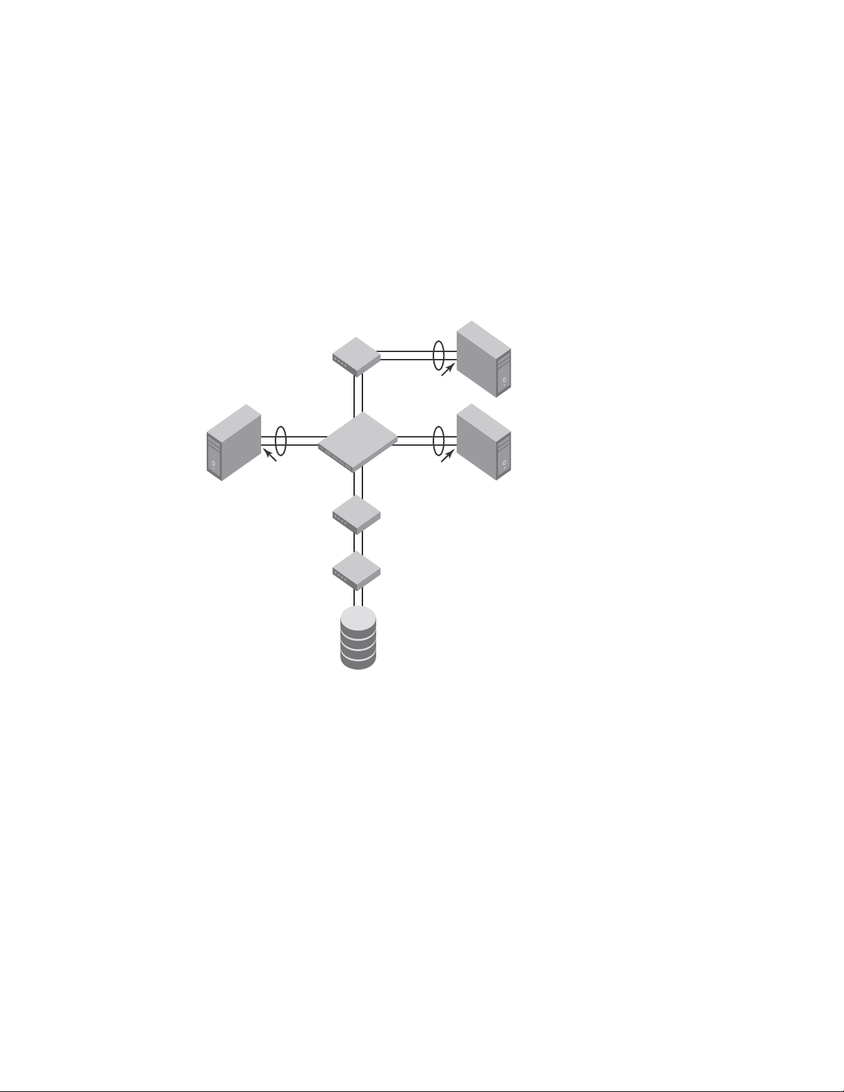
The Dell FCoE hardware contain CEE ports that support FCoE forwarding. The CEE ports are also
backwards compatible and support classic Layer 2 Ethernet networks (see Figure 1). In Layer 2
Ethernet operation, a host with a Converged Network Adapter (CNA) can be directly attached to a
CEE port on the Dell FCoE hardware. Another host with a classic 10-Gigabit Ethernet NIC can be
either directly attached to a CEE port, or attached to a classic Layer 2 Ethernet network which is
attached to the Dell FCoE hardware.
FIGURE 1 Multiple switch fabric configuration
Layer 2 Ethernet overview
1
Layer 2 forwarding
Layer 2 Ethernet frames are forwarded on the CEE ports. 802.1Q VLAN support is used to tag
incoming frames to specific VLANs, and 802.3ac VLAN tagging support is used to accept VLAN
tagged frames from external devices. The 802.1D Spanning Tree Protocol (STP), Rapid Spanning
Tree Protocol (RSTP), and Multiple Spanning Tree Protocol (MSTP) are used as the bridging
Dell Converged Enhanced Ethernet Administrator’s Guide 3
53-1002116-01
protocols between Layer 2 switches.
Page 22

Layer 2 Ethernet overview
NOTE
NOTE
1
The Dell FCoE hardware handles Ethernet frames as follows:
• When the destination MAC address is not in the lookup table, the frame is flooded on all ports
except the ingress port.
• When the destination MAC address is present in the lookup table, the frame is switched only to
the correct egress port.
• When the destination MAC address is present in the lookup table, and the egress port is the
same as the ingress port, the frame is dropped.
• If the Ethernet Frame Check Sequence (FCS) is incorrect, because the switch is in cut-through
mode, a correctly formatted Ethernet frame is sent out with an incorrect FCS.
• If the Ethernet frame is too short, the frame is discarded and the error counter is incremented.
• If the Ethernet frame is too long, the frame is discarded and the error counter is incremented.
• Frames sent to a broadcast destination MAC address are flooded on all ports except the
ingress port.
• When MAC address entries in the lookup table time out, they are removed. In this event, frame
forwarding changes from unicast to flood.
• An existing MAC address entry in the lookup table is discarded when a device is moved to a
new location. When a device is moved, the ingress frame from the new port causes the old
lookup table entry to be discarded and the new entry inserted into the lookup table. Frame
forwarding remains unicast to the new port.
• When the lookup table is full, new entries replace the oldest MAC addresses after the oldest
MAC addresses age and time out. MAC addresses that still have traffic running are not timed
out.
New entries start replacing older entries when the lookup table reaches 90 percent of its 32k
capacity.
VLAN tagging
The Dell FCoE hardware handles VLAN tagging as follows:
• If the CEE port is configured to tag incoming frames with a single VLAN ID, then incoming
frames that are untagged are tagged with the VLAN ID.
• If the CEE port is configured to tag incoming frames with multiple VLAN IDs, then incoming
frames that are untagged are tagged with the correct VLAN ID based on the port setting.
• If the CEE port is configured to accept externally tagged frames, then incoming frames that are
tagged with a VLAN ID are passed through unchanged.
Only a single switch-wide VLAN is capable of forwarding FCoE traffic.
For detailed information on configuring VLANs, see “Configuring VLANs Using the CEE CLI” on
page 31.
4 Dell Converged Enhanced Ethernet Administrator’s Guide
53-1002116-01
Page 23

Layer 2 Ethernet overview
1
Loop-free network environment
The Dell FCoE hardware uses the following protocols to maintain a loop-free network environment:
• 802.1D Spanning Tree Protocol (STP)—STP is required to create a loop-free topology in the LAN.
• Rapid Spanning Tree Protocol (RSTP)—RSTP evolved from the 802.1D STP standard. RSTP
provides for a faster spanning tree convergence after a topology change.
• Multiple Spanning Tree Protocol (MSTP)—MSTP defines an extension to RSTP to further develop
the usefulness of VLANs. With per-VLAN MSTP, you can configure a separate spanning tree for
each VLAN group. The protocol automatically blocks the links that are redundant in each
spanning tree.
Using MSTP, you can create multiple loop-free active topologies on a single physical topology.
These loop-free topologies are mapped to a set of configurable VLANs. This enables you to
better utilize the physical resources present in the network and achieve better load balancing
of VLAN traffic.
For detailed information on configuring these protocols, see “Configuring STP, RSTP, and MSTP
using the CEE CLI” on page 43.
Frame classification (incoming)
The Dell FCoE hardware is capable of classifying incoming Ethernet frames based on the following
criteria:
• Port number
• Protocol
• MAC address
The classified frames can be tagged with a VLAN ID or with 802.1p Ethernet priority. The 802.1p
Ethernet priority tagging is done using the Layer 2 Class of Service (CoS). The 802.1p Ethernet
priority is used to tag frames in a VLAN with a Layer 2 CoS to prioritize traffic in the VLAN. The Dell
FCoE hardware also accepts frames that have been tagged by an external device.
Frame classification options are as follows:
• VLAN ID and Layer 2 CoS by physical port number—With this option, the port is set to classify
incoming frames to a preset VLAN ID and the Layer 2 CoS by the physical port number on the
Dell FCoE hardware.
• VLAN ID and Layer 2 CoS by LAG virtual port number—With this option, the port is set to classify
incoming frames to a preset VLAN ID and Layer 2 CoS by the Link Aggregation Group (LAG)
virtual port number.
• Layer 2 CoS mutation—With this option, the port is set to change the Layer 2 CoS setting by
enabling the QoS mutation feature.
• Layer 2 CoS trust—With this option, the port is set to accept the Layer 2 CoS of incoming
frames by enabling the QoS trust feature.
For detailed information on configuring QoS, see “Configuring QoS using the CEE CLI” on page 93.
Dell Converged Enhanced Ethernet Administrator’s Guide 5
53-1002116-01
Page 24

Layer 2 Ethernet overview
1
Congestion control and queuing
The Dell FCoE hardware supports several congestion control and queuing strategies. As an output
queue approaches congestion, Random Early Detection (RED) is used to selectively and proactively
drop frames to maintain maximum link utilization. Incoming frames are classified into priority
queues based on the Layer 2 CoS setting of the incoming frame, or the possible rewriting of the
Layer 2 CoS field based on the settings of the CEE port or VLAN.
The Dell FCoE hardware supports a combination of two scheduling strategies to queue frames to
the egress ports; Priority queuing, which is also referred to as strict priority, and Deficit Weighted
Round Robin (DWRR) queuing.
The scheduling algorithms work on the eight traffic classes as specified in 802.1Qaz Enhanced
Transmission Selection (ETS).
Queuing features are described as follows:
• RED—RED increases link utilization. When multiple inbound TCP traffic streams are switched to
the same outbound port, and some traffic streams send small frames while other traffic
streams send large frames, link utilization will not be able to reach 100 percent. When RED is
enabled, link utilization approaches 100 percent.
• Classification—Setting user priority.
- Inbound frames are tagged with the user priority set for the inbound port. The tag is visible
when examining the frames on the outbound port. By default, all frames are tagged to
priority zero.
- Externally tagged Layer 2 frames—When the port is set to accept externally tagged Layer 2
frames, the user priority is set to the Layer 2 CoS of the inbound frames.
• Queuing
- Input queuing—Input queuing optimizes the traffic flow in the following way. Suppose a CEE
port has inbound traffic that is tagged with several priority values, and traffic from
different priority settings is switched to different outbound ports. Some outbound ports
are already congested with background traffic while others are uncongested. With input
queuing, the traffic rate of the traffic streams switched to uncongested ports should
remain high.
- Output queuing—Output queuing optimizes the traffic flow in the following way. Suppose
that several ports carry inbound traffic with different priority settings. Traffic from all ports
is switched to the same outbound port. If the inbound ports have different traffic rates,
some outbound priority groups will be congested while others can remain uncongested.
With output queuing, the traffic rate of the traffic streams that are uncongested should
remain high.
- Multicast rate limit—A typical multicast rate limiting example is where several ports carry
multicast inbound traffic that is tagged with several priority values. Traffic with different
priority settings is switched to different outbound ports. The multicast rate limit is set so
that the total multicast traffic rate on output ports is less than the specified set rate limit.
- Multicast input queuing—A typical multicast input queuing example is where several ports
carry multicast inbound traffic that is tagged with several priority values. Traffic with
different priority settings is switched to different outbound ports. Some outbound ports
are already congested with background traffic while others are uncongested. The traffic
rate of the traffic streams switched to the uncongested ports should remain high. All
outbound ports should carry some multicast frames from all inbound ports. This enables
multicast traffic distribution relative to the set threshold values.
6 Dell Converged Enhanced Ethernet Administrator’s Guide
53-1002116-01
Page 25

Layer 2 Ethernet overview
1
- Multicast output queuing—A typical multicast output queuing example is where several
ports carry multicast inbound traffic. Each port has a different priority setting. Traffic from
all ports is switched to the same outbound port. If the inbound ports have varying traffic
rates, some outbound priority groups will be congested while others remain uncongested.
The traffic rate of the traffic streams that are uncongested remains high. The outbound
ports should carry some multicast frames from all the inbound ports.
• Scheduling—A typical example of scheduling policy (using SP0 and SP1 modes) is where ports
0 through 7 carry inbound traffic, each port has a unique priority level, port 0 has priority 0,
port 1 has priority 1, and so on. All traffic is switched to the same outbound port. In SP0 mode,
all ports have DWRR scheduling; therefore, the frames-per-second (FPS) on all ports should
correspond to the DWRR settings. In SP1 mode, priority 7 traffic uses SP; therefore, priority 7
can achieve a higher FPS. Frames from input ports with the same priority level should be
scheduled in a round robin manner to the output port.
When setting the scheduling policy, each priority group that is using DWRR scheduling can be
set to use a percentage of the total bandwidth by setting the PG_Percentage parameter.
For detailed information on configuring QoS, see “Configuring QoS using the CEE CLI” on page 93.
Access control
Access Control Lists (ACLs) are used for Layer 2 switching security. Standard ACLs inspect the
source address for the inbound ports. Extended ACLs provide filtering by source and destination
addresses and protocol. ACLs can be applied to the CEE ports or to VLANs.
ACLs function as follows:
• A standard Ethernet ACL configured on a physical port is used to permit or deny frames based
on the source MAC address. The default is to permit all frames.
• An extended Ethernet ACL configured on a physical port is used to permit or deny frames
based on the source MAC address, destination MAC address, and EtherType. The default is to
permit all frames.
• A standard Ethernet ACL configured on a LAG virtual port is used to permit or deny frames
based on the source MAC address. The default is to permit all frames. LAG ACLs apply to all
ports in the LAG.
• An extended Ethernet ACL configured on a LAG virtual port is used to permit or deny frames
based on the source MAC address, destination MAC address, and EtherType. The default is to
permit all frames. LAG ACLs apply to all ports in the LAG.
• A standard Ethernet ACL configured on a VLAN is used to permit or deny frames based on the
source MAC address. The default is to permit all frames. VLAN ACLs apply to the Switch Vertical
Interface (SVI) for the VLAN.
• An extended Ethernet ACL configured on a VLAN is used to permit or deny frames based on the
source MAC address, destination MAC address, and EtherType. The default is to permit all
frames. VLAN ACLs apply to the Switch Vertical Interface (SVI) for the VLAN.
For detailed information on configuring ACLs, see “Configuring ACLs using the CEE CLI” on page 87.
Access Gateway
All ports on the switch come from the factory set to Access Gateway mode, with the default Access
Gateway mapping. See the “Access Gateway Administrator’s Guide” for full details.
Dell Converged Enhanced Ethernet Administrator’s Guide 7
53-1002116-01
Page 26

FCoE Initialization Protocol
NOTE
NOTE
NOTE
1
Trunking
The term “trunking” in an Ethernet network refers to the use of multiple network links (ports) in
parallel to increase the link speed beyond the limits of any one single link or port, and to increase
the redundancy for higher availability.
802.1ab Link Layer Discovery Protocol (LLDP) is used to detect links to connected switches or
hosts. Trunks can then be configured between an adjacent switch or host and the Dell FCoE
hardware using the VLAN classifier commands. See “Configuring an interface port as a trunk
interface” on page 37.
The Data Center Bridging (DCB) Capability Exchange Protocol (DCBX) extension is used to identify a
CEE-capable port on an adjacent switch or host. For detailed information on configuring LLDP and
DCBX, see “Configuring LLDP using the CEE CLI” on page 75.
The 802.3ad Link Aggregation Control Protocol (LACP) is used to combine multiple links to create a
trunk with the combined bandwidth of all the individual links. For detailed information on
configuring LACP, see “Configuring Link Aggregation using the CEE CLI” on page 65.
The Dell software supports a maximum 24 LAG interfaces.
Flow Control
802.3x Ethernet pause and Ethernet Priority-based Flow Control (PFC) are used to prevent dropped
frames by slowing traffic at the source end of a link. When a port on a switch or host is not ready to
receive more traffic from the source, perhaps due to congestion, it sends pause frames to the
source to pause the traffic flow. When the congestion has been cleared, it stops requesting the
source to pause traffic flow, and traffic resumes without any frame drop.
When Ethernet pause is enabled, pause frames are sent to the traffic source. Similarly, when PFC
is enabled, there is no frame drop; pause frames are sent to the source switch.
For detailed information on configuring Ethernet pause and PFC, see “Configuring QoS using the
CEE CLI” on page 93.
FCoE Initialization Protocol
The FCoE Initialization Protocol (FIP) discovers and initializes FCoE capable entities connected to
an Ethernet cloud through a dedicated Ethertype, 0x8914, in the Ethernet frame.
FIP discovery
This software version supports the October 8, 2008 (REV 1.03) of the ANSI FC Backbone
Specification with priority-tagged FIP VLAN discovery protocol and FIP version 0. This release does
not support FIP Keep Alive.
8 Dell Converged Enhanced Ethernet Administrator’s Guide
53-1002116-01
Page 27

FCoE Initialization Protocol
NOTE
The Dell FCoE hardware FIP discovery phase operates as follows:
1
• The Dell FCoE hardware uses the FCoE Initialization Protocol (FIP). Enodes discover FCFs and
initialize the FCoE connection through the FIP.
• Solicited advertisements—A typical scenario is where a Dell FCoE hardware receives a FIP
solicitation from an ENode. Replies to the original FIP solicitation are sent to the MAC address
embedded in the original FIP solicitation. After being accepted, the ENode is added to the
VN_port table.
• Login group—When enabled, replies to solicitations are sent only by Dell FCoE hardware that
have the ENode in the login group.
• VLAN 1—The Dell FCoE hardware should not forward FIP frames on VLAN 1 because it is
reserved for management traffic only.
• A fabric-provided MAC address is supported. A server-provided MAC-address is not supported
in the Fabric OS v6.3.1_cee release.
In the fabric-provided MAC address format, VN_port MAC addresses are based on a 24-bit
fabric-supplied value. The first three bytes of this value is referred to as the FCMAP. The next
three bytes are the FC ID, which is assigned by the switch when the ENode logs in to the switch.
FIP login
FIP login operates as follows:
• ENodes can log in to the Dell FCoE hardware using FIP. Fabric login (FLOGI) and fabric
discovery (FDISC) are accepted. Dell FCoE hardware in the fabric maintain the MAC address,
World Wide Name (WWN), and PID mappings per login. Each ENode port should have a unique
MAC address and WWN.
• FIP FLOGI—The Dell FCoE hardware accepts the FIP FLOGI from the ENode. The FIP FLOGI
acceptance (ACC) is sent to the ENode if the ENode MAC address or WWN matches the
VN_port table on the Dell FCoE hardware. The FIP FLOGI request is rejected if the ENode MAC
address or WWN does not match. The ENode login is added to the VN_port table. Fabric
Provided MAC addressing (FPMA) is supported.
• FIP FDISC—The Dell FCoE hardware accepts FIP FDISC from the ENode. FIP FDISC acceptance
(ACC) is sent to the ENode if the ENode MAC address or WWN matches the VN_port table on
the Dell FCoE hardware. The FIP FDISC request is rejected if the ENode MAC address or WWN
does not match. The ENode login is added to the VN_port table. FPMA is supported.
• Maximum logins per VF_port—The Dell FCoE hardware supports a maximum of 255 logins per
VF_port. The VF_port rejects further logins after the maximum is reached.
• Maximum logins per switch—The Dell FCoE hardware accepts a maximum of 1024 logins per
switch. Note that the Dell FCoE hardware does not reject further logins after the maximum is
reached.
Dell Converged Enhanced Ethernet Administrator’s Guide 9
53-1002116-01
Page 28

FCoE Initialization Protocol
NOTE
1
FIP logout
FIP logout operates as follows:
• ENodes can log out from the Dell FCoE hardware using FIP. The Dell FCoE hardware in the
fabric updates the MAC address, WWN, and PID mappings upon logout. The Dell FCoE
hardware also handles scenarios of implicit logout where the ENode has left the fabric without
explicitly logging out.
• FIP logout (LOGO)—The Dell FCoE hardware accepts a FIP LOGO from the ENode. The FIP LOGO
ACC should be sent to the ENode if the ENode MAC address matches the VN_port table on the
Dell FCoE hardware. The LOGO is ignored (not rejected) if the ENode MAC address does not
match. The ENode logout is updated in the VN_port table. FPMA is supported.
• Implicit logout—With the ENode directly connected to a CEE port, if the port that the ENode is
attached to goes offline, the Dell FCoE hardware implicitly logs out that ENode. ENode logout is
updated in the VN_port table. The Dell FCoE hardware sends FCoE LOGO on behalf of the
ENode.
FCoE login
The Dell FCoE hardware FCoE login operates as follows:
• ENodes can log in to the Dell FCoE hardware using FCoE encapsulated, FC Extended Link
Service (ELS) frames. FLOGI and FDISC are accepted. Dell FCoE hardware in the fabric
maintains the MAC address to WWN/PID mappings per login. Class 2 FLOGI is not supported.
• FCoE FLOGI—The Dell FCoE hardware accepts FCoE FLOGI from the ENode. FCoE FLOGI ACC is
sent to the ENode if the FCMAP matches the VN_port table on the Dell FCoE hardware.
Requests are ignored if the FCMAP does not match. The ENode login is added to the VN_port
table.
• FCoE FDISC—The Dell FCoE hardware accepts FCoE FDISC from the ENode. FCoE FDISC ACC is
sent to the ENode if the FCMAP matches the VN_port table on the Dell FCoE hardware. The
FCoE FDISC request is ignored if the FCMAP does not match. The ENode login is added to the
VN_port table.
• FCMAP—The Dell FCoE hardware accepts FCoE FLOGI from the ENode. The FCMAP determines
which FCoE VLAN is accepted for the FCoE session.
Only one FCoE VLAN is supported in the Fabric OS v6.3.1_cee release.
FCoE logout
The Dell FCoE hardware FCoE logout operates as follows:
• ENodes can log out from the Dell FCoE hardware using the FCoE encapsulated, FC ELS frame.
Dell FCoE hardware in the fabric updates the MAC address to WWN/PID mappings upon
logout. The Dell FCoE hardware also handles scenarios of implicit logout where the ENode has
left the fabric without explicitly logging out.
• FCoE LOGO—The Dell FCoE hardware accepts the FCoE LOGO from the ENode. The FCoE LOGO
ACC is sent to the ENode if the ENode MAC address matches the VN_port table on the Dell
FCoE hardware. The LOGO is ignored (not rejected) if the ENode MAC address does not match.
The ENode logout is updated in the VN_port table.
10 Dell Converged Enhanced Ethernet Admin istrator’s Guide
53-1002116-01
Page 29

FCoE Initialization Protocol
1
Logincfg
The Dell FCoE hardware logincfg mechanism operates as follows:
• The logincfg is the mechanism for controlling ENode logins per Dell FCoE hardware. Each unit
of Dell FCoE hardware maintains its own logincfg.
• Login configuration management is optional—when login management is disabled, the default
behavior is to accept logins from any ENode.
• Logingroup creation and deletion—The Dell FCoE hardware accepts valid logingroup names
and member WWNs. The Dell FCoE hardware rejects invalid entries. The Dell FCoE hardware
allows the deletion of logingroups that are defined and committed. You can display defined
and committed logingroups. The logingroup capability is disabled by default.
• Member add and remove—You can add valid member WWNs. Invalid WWNs are rejected.
Duplicate WWNs are uniquely resolved. You can display the current view of defined logingroups
when changes are made to the configuration.
• Commit and abort—Defined logingroup changes can be aborted with no effect on existing
sessions. The Dell FCoE hardware does not apply the configurations to new sessions until the
changes are committed. Once defined, logingroups are committed. The Dell FCoE hardware
immediately uses the new configuration.
• No traffic disruption—Changing the logingroup without committing the changes does not affect
existing sessions. After committing the changes, ENodes that were already logged in continue
to function even when that member is removed from the logingroup. New logins from the
former member are rejected.
Name server
The Dell FCoE hardware name server function operates as follows:
• ENode login and logout to and from the Dell FCoE hardware updates the name server in the FC
fabric. The Dell FCoE hardware maintains the MAC address to WWN/PID mappings.
• ENode login and logout—When an ENode login occurs through any means (FIP FLOGI, FIP
FDISC, FCoE FLOGI, or FCoE FDISC), an entry is added to the name server. When an ENode
logout occurs through any means (FIP LOGO, FCoE LOGO, or implicit logout), the entry is
removed from the name server.
• ENode data—The Dell FCoE hardware maintains a VN_port table. The table tracks the ENode
MAC address, FIP login parameters for each login from the same ENode, and WWN/PID
mappings on the FC side. You can display the VN_port table with the fcoe -loginshow port
command.
FC zoning
The Dell FCoE hardware FC zoning operates as follows:
• The virtual devices created by the Dell FCoE hardware on behalf of the ENodes are subject to
FC zoning. An ENode is only allowed to access devices in the same zones. Administrative
Domains (ADs) are not supported in the Fabric OS v6.3.1_cee release.
• ENodes can access FC devices in the same zones— FC devices that are not in the same zones
cannot be accessed. Zone members can overlap in multiple zones (that is, overlapping zones).
Zoning changes are immediately enabled by hardware enforced zoning.
Dell Converged Enhanced Ethernet Administrator’s Guide 11
53-1002116-01
Page 30

1
NOTE
NOTE
FCoE queuing
• ENodes can access all FC devices with no zoning—ENodes can access all FC devices in the
fabric when cfgdisable is issued and Default Zone is set to All Access Mode.
• Field replacement—When a Dell FCoE hardware is replaced in the field, you can perform a
configdownload on a previously saved configuration. No zoning change is required.
Registered State Change Notification (RSCN)
The Dell FCoE hardware RSCN function operates as follows:
• RSCN events generated in the FC fabric are forwarded to the ENodes. RSCN events generated
on the FCoE side are forwarded to the FC devices. CEE is not aware of RSCN events.
• Device RSCN—An RSCN is generated to all registered and affected members when an ENode
either logs in or logs out of an FCF through any means. An RSCN is generated when an FC
N_port device either logs in or logs out of the FC fabric.
When transmitting an RSCN, zoning rules still apply for FCoE devices as the devices are treated
as regular FC N_ports.
• VF_port RSCN—An RSCN is generated to all registered members when a VF_port goes online or
offline, causing ENode or FC devices to be added or removed.
• Domain RSCN—An RSCN is generated to all registered and affected members when an FC
switch port goes online or offline, causing ENode or FC devices to be added or removed. An
RSCN is generated when two FC switches merge or segment, causing ENode or FC devices to
be added or removed. When FC switches merge or segment, an RSCN is propagated to
ENodes.
• Zoning RSCN—An RSCN is generated to all registered and affected members when a zoning
exchange occurs in the FC fabric.
FCoE queuing
The QOS configuration controls the FCoE traffic distribution. Note that changing these settings
requires changes on both the Dell FCoE hardware and the CNA; therefore, the link must be taken
offline and back online after a change is made. Traffic scheduler configuration changes affect
FCoE traffic distribution as follows:
• Changing the priority group for a port causes the FCoE traffic distribution to update. The priority
group and bandwidth are updated.
• Changing the priority table for a port causes the FCoE traffic distribution to be updated. The
COS-to-priority group mapping is updated.
• Changing the class map for a port causes the FCoE traffic distribution to be updated.
• Changing the policy map for a port causes FCoE traffic distribution to be updated.
• Changing the CEE map for a port causes the FCoE traffic distribution to be updated.
• The FCMAP to VLAN mapping determines the FCoE VLAN allowed for the FCoE session.
Modifying this mapping causes the existing sessions to terminate.
Only one FCoE VLAN is supported in the Fabric OS v6.3.1_cee release.
12 Dell Converged Enhanced Ethernet Admin istrator’s Guide
53-1002116-01
Page 31

Chapter
Using the CEE CLI
In this chapter
•Management Tools . . . . . . . . . . . . . . . . . . . . . . . . . . . . . . . . . . . . . . . . . . . . . 13
•CEE Command Line Interface. . . . . . . . . . . . . . . . . . . . . . . . . . . . . . . . . . . . . 13
•Internal and external 10 Gbps Ethernet interfaces syntax . . . . . . . . . . . . . . 20
Management Tools
The Dell FCoE hardware runs traditional Fabric OS (FOS) software and can be managed using the
same tools traditionally used for SAN management. Using the FOS Command Line Interface (CLI),
administrators have access to all commands and utilities common to other Dell switches. In
addition, Fabric OS software on the Dell FCoE hardware enables Dell Web Tools to support the
following features for configuring and managing a Converged Ethernet Network:
• CEE interface display and configuration
• FCoE trunk display and configuration
• CEE configuration including link aggregation (LACP), Virtual LANs (VLANs), Quality of Service
(QoS), and LLDP (Link Layer Discovery Protocol)/ DCBX protocol (Data Center Bridging
eXchange)
• FCoE login groups
2
CEE Command Line Interface
The Dell FCoE hardware introduces a new CLI designed to support the management of CEE and
Layer 2 Ethernet switching functionality. The CEE CLI uses an industry-standard hierarchical shell
familiar to Ethernet/IP networking administrators.
All conventional port-related Fabric OS CLI commands are only applicable to Fibre Channel. These
commands have no knowledge of the Ethernet ports. The CEE features and CEE ports can only be
configured through the CEE CLI interface which is accessed by entering the cmsh command from
the Fabric OS shell.
The system starts up with the default Fabric OS configuration and the CEE startup configuration.
After logging in you are in the Fabric OS shell. For information on accessing the CEE commands
from the Fabric OS shell, see “Accessing the CEE CLI from the Fabric OS shell” on page 15.
Some Fabric OS commands are available in the CEE shell. Enter the fos ? command at the CEE CLI
Privileged EXEC mode command prompt to view the available Fabric OS commands. The traditional
Fabric OS command help found in the Fabric OS shell is not available through the CEE shell.
Dell Converged Enhanced Ethernet Administrator’s Guide 13
53-1002116-01
Page 32

CEE Command Line Interface
NOTE
2
The CEE configuration is not affected by configUpload and configDownload commands entered in
the Fabric OS shell.
Saving your configuration changes
Any configuration changes made to the switch are written into the running-config file. This is a
dynamic file that is lost when the switch reboots. During the boot sequence, the switch resets all
configuration settings to the values in the startup-config file.
To make your changes permanent, you must use either the write memory command or the copy
command to commit the running-config file to the startup--config file.
Saving configuration changes with the copy command
Perform this task from Privileged EXEC mode.
1. Enter the copy command to save the running-config file to the startup-config file.
switch#copy running-config startup-config
Saving configuration changes with the write command
Perform this task from Privileged EXEC mode.
1. Enter the write memory command to save the running-config file to the startup-config file.
switch# write memory
Overwrite the startup config file (y/n): y
Building configuration...
CEE CLI RBAC permissions
Role-Based Action Control (RBAC) defines the capabilities that a user account has based on the
role the account has been assigned. Table 2 displays the permissions matrix for CEE. Permissions
are specifically defined as follows:
• OM—When you enter the cmsh command, you are put directly into Privileged EXEC mode.
• O—When you enter the cmsh command, you are limited to EXEC mode.
• N—You are not allowed access to the CEE CLI.
TABLE 2 CEE RBAC permissions
Root Factory UserID User Operator SwitchAdmin FabricAdmin ZoneAdmin BasicSwitchAdmin SecurityAdmin
OM OM OM O N O OM N N O
O = observe, OM = observe and modify, N = access not allowed
14 Dell Converged Enhanced Ethernet Admin istrator’s Guide
53-1002116-01
Page 33

CEE Command Line Interface
NOTE
NOTE
Protocol configurationInterface configuration
Port-channel
10-Gigabit Ethernet
VLAN
CEE CLI features
CEE map
ACLs
Console and VTY (line)
configuration
Console
Virtual terminal
Global configuration
EXEC
Privileged EXEC
LLDP
Spanning-tree
2
Accessing the CEE CLI through the console or Telnet
While this example uses the UserID role to log in to the switch, any role listed in the “CEE CLI RBAC
permissions” section can be used.
The procedure to access the CEE CLI is the same through either the console interface or through a
Telnet session; both access methods bring you to the login prompt.
switch login: userid
Password:
switch:admin> cmsh
switch#
To return to the Fabric OS CLI, enter the following command.
switch#exit
switch:admin>
Multiple users can Telnet and issue commands using the Exec mode and the Privileged Exec mode.
Accessing the CEE CLI from the Fabric OS shell
To enter the CEE CLI from the Fabric OS shell, enter the following command.
switch:admin> cmsh
switch#
To return to the Fabric OS shell, enter the following command.
switch#exit
switch:admin>
CEE CLI command modes
Figure 2 displays the CEE CLI command mode hierarchy.
FIGURE 2 CEE CLI command mode hierarchy
Dell Converged Enhanced Ethernet Administrator’s Guide 15
53-1002116-01
Tab le 3 lists the CEE CLI command modes and describes how to access them.
Page 34

CEE Command Line Interface
NOTE
2
At system startup, if you try to enter Privileged EXEC mode before the system has fully booted, the
following message is displayed:
%Info: Please wait. System configuration is being loaded.
After the system has fully booted, a RASLOG message indicates that the CEE CLI is ready to accept
configuration commands.
TABLE 3 CEE CLI command modes
Command
mode
EXEC switch> Enter the cmsh command at the
Privileged
EXEC
Global
configuration
Interface
configuration
Prompt How to access the command mode Description
Fabric OS prompt after you have
logged in as an appropriate user.
switch# From the EXEC mode, enter the
enable command.
switch(config)# From the EXEC mode, enter the
configure terminal EXEC command.
Port-channel:
switch(conf-if-po-63)#
10-Gigabit Ethernet (CEE port):
switch(conf-if-te-0/1)#
From the global configuration mode,
specify an interface by entering one
of the following interface types:
• interface port-channel
• interface intengigabitethernet
• interface vlan
VLAN:
switch(conf-if-vl-1)#
Protocol
configuration
LLDP:
switch(conf-lldp)#
Spanning-tree:
switch(conf-mstp)#
switch(conf-rstp)#
switch(conf-stp)#
From the global configuration mode,
specify a protocol by entering one of
the following protocol types:
• protocol lldp
• protocol spanning-tree mstp
• protocol spanning-tree rstp
• protocol spanning-tree stp
Display running system
information and set
terminal line
parameters.
Display and change
system parameters.
Note that this is the
administrative mode
and also includes EXEC
mode commands.
Configure features that
affect the entire switch.
Access and configure
individual interfaces.
Access and configure
protocols.
16 Dell Converged Enhanced Ethernet Admin istrator’s Guide
53-1002116-01
Page 35

NOTE
NOTE
TABLE 3 CEE CLI command modes
CEE Command Line Interface
2
Command
mode
Feature
configuration
Console and
VTY (line)
configuration
Prompt How to access the command mode Description
CEE map:
switch(config-ceemap)#
Standard ACL:
switch(conf-macl-std)#
Extended ACL:
switch(conf-macl-ext)#
switch(config-line)# From the global configuration mode,
From the global configuration mode,
specify a CEE feature by entering
one of the following feature names:
• cee-map
• mac access-list
configure a terminal connected
through the console port by entering
the line console command.
Configure a terminal connected
through a Telnet session by entering
the line vty command.
Access and configure
CEE features.
Configure a terminal
connected through the
console port or a
terminal connected
through a Telnet
session.
Pressing Ctrl+Z or entering the end command in any mode returns you to Privileged EXEC mode.
Entering exit in any mode returns you to the previous mode.
CEE CLI keyboard shortcuts
Tab le 4 lists CEE CLI keyboard shortcuts.
TABLE 4 CEE CLI keyboard shortcuts
Keystroke Description
Ctrl+B or the left arrow key. Moves the cursor back one character.
Ctrl+F or the right arrow key. Moves the cursor forward one character.
Ctrl+A Moves the cursor to the beginning of the command line.
Ctrl+E Moves the cursor to the end of the command line.
Esc B Moves the cursor back one word.
Esc F Moves the cursor forward one word.
Ctrl+Z Returns to Privileged EXEC mode.
Ctrl+P or the up arrow key. Displays commands in the history buffer with the most recent command
displayed first.
Ctrl+N or the down arrow key. Displays commands in the history buffer with the most recent command
displayed last.
In EXEC and Privileged EXEC modes, use the show history command to list the commands most
recently entered. The switch retains the history of the last 1000 commands entered from all
terminals.
Dell Converged Enhanced Ethernet Administrator’s Guide 17
53-1002116-01
Page 36

CEE Command Line Interface
2
Using the do command as a shortcut
You can use the do command to save time when you are working in any configuration mode and
you want to run a command in the EXEC or Privileged EXEC mode.
For example, if you are configuring an LLDP and you want to execute a Privileged EXEC mode
command, such as the dir command, you would first have to exit the LLDP configuration mode.
However, by using the do command with the dir command you can ignore the need to change
configuration modes, as shown in the following example.
switch(conf-lldp)#do dir
Contents of flash://
-rw-r----- 1276 Wed Feb 4 07:08:49 2009 startup_rmon_config
-rw-r----- 1276 Wed Feb 4 07:10:30 2009 rmon_config
-rw-r----- 1276 Wed Feb 4 07:12:33 2009 rmon_configuration
-rw-r----- 1276 Wed Feb 4 10:48:59 2009 starup-config
switch(conf-lldp)#
Displaying CEE CLI commands and command syntax
Enter a question mark (?) in any command mode to display the list of commands available in that
mode.
switch>?
Exec commands:
enable Turn on privileged mode command
exit End current mode and down to previous mode
help Description of the interactive help system
logout Exit from the EXEC
quit Exit current mode and down to previous mode
show Show running system information
terminal Set terminal line parameters
To display a list of commands that start with the same characters, type the characters followed by
the question mark (?).
switch>e?
enable Turn on privileged mode command
exit End current mode and down to previous mode
To display the keywords and arguments associated with a command, enter the keyword followed by
the question mark (?).
switch#terminal ?
length Set number of lines on a screen
no Negate a command or set its defaults
If the question mark (?) is typed within an incomplete keyword, and the keyword is the only keyword
starting with those characters, the CLI displays help for that keyword only.
switch#show d?
dot1x IEEE 802.1X Port-Based Access Control
<cr>
If the question mark (?) is typed within an incomplete keyword but the keyword matches several
keywords, the CLI displays help for all the matching keywords.
switch#show i?
interface Interface status and configuration
ip Internet Protocol (IP)
18 Dell Converged Enhanced Ethernet Admin istrator’s Guide
53-1002116-01
Page 37

CEE Command Line Interface
2
The CEE CLI accepts abbreviations for commands. This example is the abbreviation for the show
qos interface all command.
switch#sh q i a
If the switch does not recognize a command after Enter is pressed, an error message displays.
switch#hookup
^
% Invalid input detected at '^' marker.
If an incomplete command is entered, an error message displays.
switch#show
% Incomplete command.
CEE CLI command completion
To automatically complete the spelling of commands or keywords, begin typing the command or
keyword and then press Tab. For example, at the CLI command prompt type te and press Tab :
switch#te
The CLI displays:
switch#terminal
If there is more than one command or keyword associated with the characters typed, the CEE CLI
displays all choices. For example, at the CLI command prompt type show l and press Tab:
switch#show l
The CLI displays:
switch#show l
lacp line lldp
CEE CLI command output modifiers
You can filter the output of the CEE CLI show commands using the output modifiers described in
Tab le 5.
TABLE 5 CEE CLI command output modifiers
Output modifier Description
redirect Redirects the command output to the specified file.
include Displays the command output that includes the specified expression.
exclude Displays the command output that excludes the specified expression.
append Appends the command output to the specified file.
begin Displays the command output that begins with the specified expression.
last Displays only the last few lines of the command output.
tee Redirects the command output to the specified file. Note that this modifier also
displays the command output.
Dell Converged Enhanced Ethernet Administrator’s Guide 19
53-1002116-01
Page 38

Internal and external 10 Gbps Ethernet interfaces syntax
2
Internal and external 10 Gbps Ethernet interfaces syntax
Fabric OS v6.3.1_cee uses two separate interface operands to refer to internal and external
10Gbps Ethernet ports; intengigabitethernet and extengigabitethernet.
Internal interfaces are assigned to ports 1 through 14. External interfaces are assigned to ports 15
through 22. The usual format for the 10 Gbps Ethernet interface is either intengigabitethernet
slot/port or extengigabitethernet slot/port.
20 Dell Converged Enhanced Ethernet Admin istrator’s Guide
53-1002116-01
Page 39

Chapter
Initial FCoE and CEE Configuration
In this chapter
•Overview. . . . . . . . . . . . . . . . . . . . . . . . . . . . . . . . . . . . . . . . . . . . . . . . . . . . . . 21
•Configuring the FCoE interfaces. . . . . . . . . . . . . . . . . . . . . . . . . . . . . . . . . . . 21
•Configuring the CEE interfaces. . . . . . . . . . . . . . . . . . . . . . . . . . . . . . . . . . . . 23
•Configuring DCBX . . . . . . . . . . . . . . . . . . . . . . . . . . . . . . . . . . . . . . . . . . . . . . 24
•Configuring Spanning Tree Protocol . . . . . . . . . . . . . . . . . . . . . . . . . . . . . . . . 25
•Configuring VLAN membership. . . . . . . . . . . . . . . . . . . . . . . . . . . . . . . . . . . . 25
•Configuring protect mode . . . . . . . . . . . . . . . . . . . . . . . . . . . . . . . . . . . . . . . . 26
Overview
This chapter describes how to configure Fibre Channel over Ethernet (FCoE) and Converged
Enhanced Ethernet (CEE) properties on the switch using CEE CLI commands. For detailed
information about all the CEE CLI commands, refer to the Converged Enhanced Ethernet Command
Reference Supporting Fabric OS v6.4.0 (53-1001762-01).
3
All of the CLI commands are entered using the Telnet or console interface on the Dell FCoE
hardware. See “CEE CLI command modes” on page 15 for complete instructions on logging into the
Dell FCoE hardware.
Configuring the FCoE interfaces
FCoE maps are used to configure FCoE properties on interfaces. An FCoE map is a placeholder for
an FCoE VLAN and a CEE map. You can assign FCoE maps on to physical interfaces using the
fcoeport command. On assigning an FCoE map onto interface:
• The corresponding FCoE VLAN is applied to the interface.
• The corresponding CEE map is applied to the interface.
• The FCoE/FIP vlan classifiers are applied to the interface.
In short, the interface becomes capable of carrying FCoE traffic. The FCoE map can be applied on
an interface only if the FCoE map is complete in all aspects. That is, it should have an FCoE VLAN
and a CEE map associated with it.
In short, the interface becomes capable for carrying FCoE traffic. FCoE map can be applied on an
interface, only if the FCoE map is complete in all respect. That is, it should have an FCoE VLAN and
a CEE map associated with it.
Dell Converged Enhanced Ethernet Administrator’s Guide 21
53-1002116-01
Page 40

Configuring the FCoE interfaces
NOTE
NOTE
3
Only a single FCoE map is allowed, which is created automatically with the name “default.” You are
not be able to delete or rename this map. By default, if there are no other conflicting
configurations, the FCoE VLAN associated to the FCoE map is FCoE VLAN (1002) and the CEE map
associated is default CEE map (also called “default”).
The default startup-configuration file contains the following settings.
• priority-group-table 1 weight 40 pfc
• priority-group-table 2 weight 60
• priority-table 2 2 2 1 2 2 2 2
Configuring FCoE VLAN
By default, if there is no preexisting FCoE VLAN, one is created and assigned the VLAN ID of 1002.
But if the system already contains an FCoE VLAN, then that VLAN is considered the default VLAN
and is associated to the FCoE map. Only one FCoE VLAN can exist at a time.
If the system boots without any FCoE VLANs, but with VLAN 1002 assigned as a LAN VLAN, the
default FCoE VLAN is automatically assigned a different VLAN ID, depending on availability.
FCoE VLAN can be created from FCoE map mode as well. The fcoe-vlan VLAN ID command creates
the FCoE VLAN, if the corresponding VLAN does not exist in the system. If a VLAN already exists with
VLAN ID, then the command fails.
Make sure your converged mode interface is not configured to classify untagged packets to the
same VLAN as the incoming VLAN-tagged packets. By configuring a converged interface to classify
untagged packets (by using classifiers or the default port VLAN ID) to th e sam e VLA N as V LAN- tagg ed
packets coming into the interface, the FCoE hardware sends out untagged packets to the CNA.
These packets may be dropped, disrupting communications.
The FCoE VLANs can be seen using show vlan fcoe. Alternatively, show vlan brief can also be used,
in which FCoE VLANs are marked with an “(F)”.
No VLAN classifiers (including FIP/FCoE classifiers) are allowed to be configured for FCoE VLAN.
To configure the FCoE VLAN, perform the following steps in global configuration mode.
1. Create the FCoE map and enter FCoE map mode.
switch(config)#fcoe-map default
2. Configure the FCoE VLAN for the FCoE map and delete the previous FCoE VLAN.
switch(conf-fcoe-map)#fcoe-vlan 5
The new FCoE VLAN 5 is created and the previous FCoE VLAN 1002 is deleted. This command
succeeds only if VLAN 5 can be created and VLAN 1002 can be deleted.
3. Display the fcoe map to ensure the successful creation.
switch(conf-fcoe-map)#do show fcoe-map
fcoe-map default
cee-map :default
fcoe-vlan :6
interface(s) :
22 Dell Converged Enhanced Ethernet Admin istrator’s Guide
53-1002116-01
Page 41

Configuring the CEE interfaces
3
Assigning FCoE map on to an interface
The FCoE map cannot be edited, if it is associated to any interfaces.
The FCoE map can be applied, irrespective of whether the interface is in ‘switchport’ or not. But the
FCoE map cannot be applied on an interface, if the same interface already has a CEE map
assigned to it.
To assign the FCoE map to an interface, perform the following steps in global configuration mode.
1. Enter interface configuration mode.
switch(config)#interface intengigabitethernet 0/0
2. Use the fcoeport command to assign the FCoE map to the interface
switch(conf-if-te-0/0)#fcoeport
3. Enter the shutdown command to toggle the availability of the interface.
To enable the interface:
switch(conf-if-te-0/0)#no shutdown
To disable the interface:
switch(conf-if-te-0/0)#shutdown
4. Display the fcoe map to ensure the successful creation.
switch(conf-fcoe-map)#do show fcoe-map
fcoe-map default
cee-map :default
fcoe-vlan :6
interface(s) :te0/0
5. Repeat this procedure for any additional interfaces.
Configuring the CEE interfaces
Traffic from downstream CEE interfaces can be assigned to a VLAN using several methods:
• The VLAN tag contained in the incoming frame
• The VLAN classifiers
• The Port-VLAN ID (PVID)
Because the Ethernet uplink ports from the Dell FCoE hardware to the distribution layer switches
will carry traffic for multiple VLANs, they are configured as 802.1q trunk ports.
The downstream CEE ports connected to the server CNAs are configured as access ports with a
PVID of either 10 or 20. The VLAN classifier group created for the FIP and FCoE EtherTypes must be
applied to the interfaces in order to place FCoE traffic on the correct VLAN. The CEE map is also
applied to the interface.
If an interface is already assigned as an fcoeport, you cannot apply the CEE map to that interface.
Only a single CEE map is allowed, which is created automatically with the name “default.” You are
not be able to delete or rename this map.
Dell Converged Enhanced Ethernet Administrator’s Guide 23
53-1002116-01
Page 42

Configuring DCBX
NOTE
3
To configure the CEE interfaces, perform the following steps in global configuration mode.
1. Assign VLANs to the uplink Ethernet port.
You must repeat this step for all uplink interfaces. For details, see “Configuring an interface
port as a trunk interface” on page 37.
The following example assigns VLAN 10 and VLAN 20 to the uplink Ethernet port.
switch(config)#interface intengigabitethernet 0/1
switch(conf-if-te-0/1)#switchport
switch(conf-if-te-0/1)#switchport mode trunk
switch(conf-if-te-0/1)#switchport trunk allowed vlan add 10
switch(conf-if-te-0/1)#switchport trunk allowed vlan add 20
switch(conf-if-te-0/1)#no shutdown
2. Apply the VLAN classifier group to the interfaces. For details, see “Activating a VLAN classifier
group with an interface port” on page 40.
The following example applies a VLAN classifier group 1 to the interfaces.
switch(config)#interface intengigabitethernet 0/10
switch(conf-if-te-0/1)#switchport
switch(conf-if-te-0/1)#switchport mode access
switch(conf-if-te-0/1)#switchport access vlan 10
switch(conf-if-te-0/1)#vlan classifier activate group 1 vlan 100
switch(conf-if-te-0/1)#no shutdown
3. Apply the CEE map to the interfaces. For details, see “Applying a CEE provisioning map to an
interface” on page 110.
The following example applies the map name.
switch(conf-if-te-0/1)#cee default
4. Enter the copy command to save the running-config file to the startup-config file.
switch(conf-if-te-0/1)#exit
switch(config)#end
switch#copy running-config startup-config
Configuring DCBX
DCBX (Data Center Bridging eXchange Protocol) runs on CEE links and is an extension of the Link
Layer Discovery Protocol (LLDP). The primary goal of DCBX is to allow the discovery of CEE-capable
hosts and switches and allow CEE-specific parameters—such as those for ETS and PFC—to be sent
before the link is shared. DCBX parameters use a type-length-value (TLV) format. By default, DCBX
is turned on, but there are two TLVs that must be enabled to support FCoE on a CEE link:
• dcbx-fcoe-app-tlv – IEEE Data Center Bridging eXchange FCoE Application TLV.
• dcbx-fcoe-logical-link-tlv - IEEE Data Center Bridging eXchange FCoE Logical Link TLV. The
presence of this TLV declares that the FCoE part of the converged link is UP.
To configure the TLVs for DCBX, perform the following steps in global configuration mode.
1. Set the protocol type to LLDP.
switch(config)#protocol lldp
24 Dell Converged Enhanced Ethernet Admin istrator’s Guide
53-1002116-01
Page 43

2. Activate the protocol.
switch(conf-lldp)#no disable
3. Activate the TLV formats using the advertise command in Protocol LLDP Configuration Mode.
switch(conf-lldp)#advertise dcbx-fcoe-app-tlv
switch(conf-lldp)#advertise dcbx-fcoe-logical-link-tlv
4. Enter the copy command to save the running-config file to the startup-config file.
switch(conf-lldp)#exit
switch(config)#end
switch#copy running-config startup-config
Configuring Spanning Tree Protocol
Spanning Tree Protocol is a mechanism to detect and avoid loops in Ethernet networks by
establishing a fixed path between all the switches in a LAN. The Dell FCoE hardware supports three
spanning tree variations: Standard Spanning Tree (STP), Rapid Spanning Tree (RSTP), and Multiple
Instance Spanning Tree (MSTP).
It is best practice that an access layer switch does not become the root switch. Changing the bridge
or STP priority helps to ensure that this does not occur. The following example performed from the
CEE CLI configures the switch for RSTP and sets the bridge priority to the highest value ensuring it
will not become the root switch in an existing LAN.
Configuring Spanning Tree Protocol
3
To configure RSTP, perform the following steps in global configuration mode.
1. Configure the switch for RSTP.
switch(config)#protocol spanning-tree rstp
2. Set the bridge priority to the highest value so it does not become the root switch in an existing
LAN.
switch(conf-rstp)#bridge-priority 61440
3. Enter the copy command to save the running-config file to the startup-config file.
switch(conf-rstp)#exit
switch(config)#end
switch#copy running-config startup-config
Configuring VLAN membership
IEEE 802.1q Virtual LANs (VLANs) provide the capability to overlay the physical network with
multiple virtual networks. VLANs allow network traffic isolation into separate virtual networks
reducing the size of administrative and broadcast domains.
A VLAN contains end stations that have a common set of requirements which can be in
independent physical locations. You can group end stations in a VLAN even if they are not physically
located in the same LAN segment. VLANs are typically associated with IP subnets and all the end
stations in a particular IP subnet belong to the same VLAN.
In addition to creating a special VLAN for FCoE traffic, VLAN classifiers are applied to incoming
EtherTypes for FCoE Initiation Protocol (FIP) and FCoE. VLAN classifiers are rules used to
dynamically classify Ethernet frames on an untagged interface to VLANs.
Dell Converged Enhanced Ethernet Administrator’s Guide 25
53-1002116-01
Page 44

Configuring protect mode
3
To configure VLAN membership, perform the following steps in global configuration mode.
1. Create the VLAN interfaces on the Dell FCoE hardware using the CEE CLI. For details, see
“Creating a VLAN interface” on page 35.
The following example creates two VLAN interfaces and assigning each one to a server group.
switch(config)#interface vlan 10
switch-cmsh(conf-if-vl-10)#description server group 1
switch(config)#interface vlan 20
switch-cmsh(conf-if-vl-20)#description server group 2
switch(config)#interface vlan 100
switch-cmsh(conf-if-vl-100)#description FCoE VLAN
2. Create VLAN rules and a VLAN classifier group for these two EtherTypes. For details, see
“Creating a VLAN classifier group and adding rules” on page 39.
The following example creates VLAN rules and classifier groups.
switch(config)#vlan classifier rule 1 proto fip encap ethv2
switch(config)#vlan classifier rule 2 proto fcoe encap ethv2
switch(config)#vlan classifier group 1 add rule 1
switch(config)#vlan classifier group 1 add rule 2
3. Apply the VLAN classifier group to any CEE interface. This step is optional. For details, see
“Activating a VLAN classifier group with an interface port” on page 40.
4. Enter the copy command to save the running-config file to the startup-config file.
switch(config)#end
switch#copy running-config startup-config
Configuring protect mode
IBM’s Advanced Management Module (AMM) can set or control certain attributes of the switch
through a backend I2C bus. The switch receives these AMM settings by reading the I2C control
registers and VPD. Additionally, AMM informs the switch if there are any changes in these settings
while the system is running by setting the appropriate bits inthe I2C control registers and
generating interrupts.
Enabling protect mode is a two-step process. First, enable protect mode on AMM. Refer to the IBM
publication titled IBM BladeCenter Advanced Management Module Protect Mode. The second task
is to enable Protect Mode on the switch by performing the following steps in global configuration
mode.
1. Select an external interface to configure as an IP interface.
switch(config)#interface extengigabitethernet 0/16
2. Configure the interface as an IP interface
switch(conf-if-te-0/16)#ip address 10.0.0.1 5
3. Return to Privileged EXEC mode.
switch(conf-if-te-0/16)#exit
switch(config)#exit
4. Enable protect mode.
switch#protect-mode enable
26 Dell Converged Enhanced Ethernet Admin istrator’s Guide
53-1002116-01
Page 45

Chapter
NOTE
Configuring IP static routes
In this chapter
•IP static routes overview . . . . . . . . . . . . . . . . . . . . . . . . . . . . . . . . . . . . . . . . . 27
•Configuring IP static routes. . . . . . . . . . . . . . . . . . . . . . . . . . . . . . . . . . . . . . . 28
IP static routes overview
Switches forward packets using routing data that is either configured manually or dynamically
created using a routing protocol. Static routes define an explicit path between two networking
devices. Unlike a dynamic routing protocol, static routes are not automatically updated and are
manually reconfigured.
Routes generated by dynamic routing protocols cannot be redistributed into the static routing
tables, but static routes can be redistributed into dynamic routing protocols. You cannot prevent
routing loops from using static routes.
4
Static routes are useful for smaller networks with only one path to an outside network and to
provide security for a larger network for certain types of traffic or links to other networks that need
more control. In general, most networks use dynamic routing protocols to communicate between
networking devices but may have one or two static routes configured for special cases.
Fabric OS v6.3.1_cee supports IPv4 static routes with Layer 2 and Layer 3 data forwarding for
eAnvil-based platforms. The following features of IP static routes are supported:
• Static routes
• Directly attached static routes
• Recursive static routes
• Floating static routes
Fully specified static routes are not supported by Fabric OS v6.3.1_cee.
The following table explains the maximum values supported for the following features
TABLE 6 IP static route features and capabilities
Feature Capability
Interface with IP Address 128
ECMP 63
Members per ECMP 64
LAG 63
Members per LAG 64
Dell Converged Enhanced Ethernet Administrator’s Guide 27
53-1002116-01
Page 46

Configuring IP static routes
NOTE
NOTE
4
TABLE 6 IP static route features and capabilities
Feature Capability
Static Routes Less than 2048, which are shared between IP
ARPs 1024 (due to Linux IP stack limitation)
Configuring IP static routes
In directly attached static routes, only the output interface is specified. The destination is assumed
to be directly attached to this interface, so the packet destination is used as the next-hop address.
Directly attached static routes are candidates for insertion in the IPv4 routing table only if they refer
to a valid IPv4 interface; that is, an interface that is both up and has IPv4 enabled on it. This
configuration is not recommended because when the next hop of a static route points to an
interface, the router considers each of the hosts within the range of the route to be directly
connected through that interface. With this type of configuration, a router performs Address
Resolution Protocol (ARP) on the Ethernet for every destination the router finds through the default
route because the router considers all of these destinations as directly connected to internal 10
Gbps interface 0/1. This kind of default route, especially if it is used by a lot of packets to many
different destination subnets, can cause high processor utilization and a large ARP cache.
address’ and static routes)
eAnvil Chip capability 12288
Anvil Chip capability 16384
Specifying a numerical next hop on a directly connected interface prevents the router from
performing ARP or each destination address. However, if the interface with the next hop goes down
and the numerical next hop is reachable through a recursive route, you should specify both the next
hop IP address and the interface through which the next hop should be found.
By default, static routes are preferred to routes learned by routing protocols. Therefore, you can
configure an administrative distance with a static route if you want the static route to be overridden
by dynamic routes. For example, you could have routes installed by the Open Shortest Path First
(OSPF) protocol with an administrative distance of 120. To have a static route that would be
overridden by an OSPF dynamic route, specify an administrative distance greater than 120.
The following example shows all destinations with address prefix 1.1.1.1/32 are directly reachable
through internal 10 Gbps interface 0/1, with an administrative distance of 1.
switch(config)#ip route 1.1.1.1/32 intengigabitethernet 0/1 1
Fabric OS v6.3.1_cee allows 64 ECMP routes. Once this pool is exhausted, any additional ECMP
routes are automatically rejected. If one of the existing ECMP routes is deleted, previously rejected
ECMP routes must be re-added manually.
28 Dell Converged Enhanced Ethernet Admin istrator’s Guide
53-1002116-01
Page 47

Configuring IP static routes
4
Recursive IP static routes
In a recursive IP static route, only the next hop is specified. The output interface is derived from the
next hop. A recursive IP static route is valid (that is, it is a candidate for insertion in the routing
table) only when the specified next hop resolves, either directly or indirectly, to a valid output
interface, provided the route does not self-recurse, and the recursion depth does not exceed the
maximum IPv4 forwarding recursion depth. Fabric OS v6.3.1_cee supports one level of recursion.
Beyond this level of recursion the routes are held as inactive routes.
Dell does not recommend manually configuring a self-recursive IP static route, although it is not
prohibited. However, a recursive IP static route that has been inserted in the routing table may
become self-recursive as a result of some transient change in the network learned through a
dynamic routing protocol. If this occurs, the fact that the IP static route has become self-recursive is
detected and is removed from the routing table, although not from the configuration. A subsequent
network change may cause the IP static route to no longer be self-recursive, in which case it is
reinserted in the routing table.
The following example specifies that all destinations with address prefix 1.1.1.1/32 are reachable
via the host with address 2.2.2.2.
switch(config)#ip route 1.1.1.1/32 2.2.2.2
Floating IP static routes
Floating IP static routes act as a alternative path to dynamic routes learned through configured
routing protocols. A floating IP static route is configured with a higher administrative distance than
the dynamic routing protocol. As a result, the dynamic route learned through the routing protocol is
always used in preference to the floating IP static route. If the dynamic route learned through the
routing protocol is lost, the floating IP static route is used in its place.
A floating IP static route must be configured with an administrative distance that is greater than the
administrative distance of the dynamic routing protocol, because routes with smaller
administrative distances are preferred. For example, if your Open Shortest Path First (OSPF)
protocol is configured with an administrative distance of 120, specify an administrative distance
greater than 120 for your floating IP static route.
The following example defines a floating IP static route that shows all destinations with address
prefix 1.1.1.1/32 are reachable through internal 10 Gbps interface 0/1:
switch(config)#ip route 1.1.1.1/32 intengigabitethernet 0/1 121
Displaying and clearing IP static routes
To display the current IP routing information and clear the assigned settings, perform the following
procedure from EXEC mode.
1. Display a summary of the IP routing table.
switch>show ip route summary
Route Source Networks Subnets Overhead Memory (bytes)
connected 0 1 64 160
static 1 1 128 320
internal 1 1180
Total 2 2 192 1660
Dell Converged Enhanced Ethernet Administrator’s Guide 29
53-1002116-01
Page 48

Configuring IP static routes
4
2. Display the detailed information about all the IP static routes.
switch>show ip route all
Codes: C - connected, S - static, R - RIP, M - mobile, B - BGP
D - EIGRP, EX - EIGRP external, O - OSPF, IA - OSPF inter area
N1 - OSPF NSSA external type 1, N2 - OSPF NSSA external type 2
E1 - OSPF external type 1, E2 - OSPF external type 2, E - EGP
i - IS-IS, su - IS-IS summary, L1 - IS-IS level-1, L2 - IS-IS level-2
ia - IS-IS inter area, * - candidate default, U - per-user static route
o - ODR, P - periodic downloaded static route
Gateway of last resort is 10.32.144.1 to network 0.0.0.0
10.0.0.0/8 is variably subnetted, 2 subnets, 2 masks
S 10.0.0.0/8 [1/0] via 10.32.144.1
C 10.32.144.0/20 is directly connected, GigabitEthernet4/47
S* 0.0.0.0/0 [1/0] via 10.32.144.1
3. Use the clear ip route command to remove a static ip route.
switch>clear ip route 10.0.0.0/8
4. Optional: Use the clear ip route command to remove all static ip routes.
switch>clear ip route all
30 Dell Converged Enhanced Ethernet Admin istrator’s Guide
53-1002116-01
Page 49

Chapter
NOTE
Configuring VLANs Using the CEE CLI
In this chapter
•VLAN overview . . . . . . . . . . . . . . . . . . . . . . . . . . . . . . . . . . . . . . . . . . . . . . . . . 31
•Ingress VLAN filtering . . . . . . . . . . . . . . . . . . . . . . . . . . . . . . . . . . . . . . . . . . . 31
•VLAN configuration guidelines and restrictions . . . . . . . . . . . . . . . . . . . . . . 33
•Default VLAN configuration. . . . . . . . . . . . . . . . . . . . . . . . . . . . . . . . . . . . . . . 33
•VLAN configuration and management . . . . . . . . . . . . . . . . . . . . . . . . . . . . . . 34
•Configuring protocol-based VLAN classifier rules . . . . . . . . . . . . . . . . . . . . . 38
•Configuring the MAC address table . . . . . . . . . . . . . . . . . . . . . . . . . . . . . . . . 40
VLAN overview
IEEE 802.1Q Virtual LANs (VLANs) provide the capability to overlay the physical network with
multiple virtual networks. VLANs allow you to isolate network traffic between virtual networks and
reduce the size of administrative and broadcast domains.
5
A VLAN contains end stations that have a common set of requirements that are independent of
physical location. You can group end stations in a VLAN even if they are not physically located in the
same LAN segment. VLANs are typically associated with IP subnetworks and all the end stations in
a particular IP subnet belong to the same VLAN. Traffic between VLANs must be routed. VLAN
membership is configurable on a per interface basis.
The VLAN used for carrying FCoE traffic needs to be explicitly designated as the FCoE VLAN. FCoE
VLANs are configured through the CEE CLI (see “Configuring a VLAN interface to forward FCoE
traffic” on page 36).
Currently only one VLAN can be configured as the FCoE VLAN.
Ingress VLAN filtering
A frame arriving at Dell FCoE hardware is either associated with a specific port or with a VLAN,
depending on whether the frame is tagged or untagged:
• Admit tagged frames only—The port the frame came in on is assigned to a single VLAN or to
multiple VLANs depending on the VLAN ID in the frame’s VLAN tag. This is called trunk mode.
• Admit untagged frames only—These frames are assigned the port VLAN ID (PVID) assigned to
the port the frame came in on. This is called access mode.
Dell Converged Enhanced Ethernet Administrator’s Guide 31
53-1002116-01
Page 50

Ingress VLAN filtering
NOTE
Is the port
a trunk?
Assign the
frame to the
classified VLAN
Assign the
frame to the
configured PVID
Drop frame
Drop frame
Is the VLAN ID
an allowed VLAN?
Assign the frame to the
VLAN present in the VLAN ID
field of the Ethernet header
Incoming frame
on an interface
No
No
No
Ye s
Ye s
Is the port an
access interface?
No
Ye s
Ye s
Does the frame match any
of the configured VLAN classifiers
(MAC address based and
protocol based)?
5
• Admit VLAN tagged and untagged frames—All tagged and untagged frames would be
processed as follows:
- All untagged frames are classified into native VLANs.
- All frames egressing are untagged for the native VLANs.
- Any tagged frames coming with a VLAN tag equal to the configured native VLAN are
processed.
- For ingress and egress, non-native VLAN tagged frames are processed according to the
allowed VLAN user specifications. This is called converged mode.
Ingress VLAN filtering is enabled by default on all Layer 2 interfaces. This ensures that VLANs are
filtered on the incoming port (depending on the user configuration).
Figure 3 displays the frame processing logic for an incoming frame.
FIGURE 3 Ingress VLAN filtering
32 Dell Converged Enhanced Ethernet Admin istrator’s Guide
There are important facts you should know about Ingress VLAN filtering:
• Ingress VLAN filtering is based on port VLAN membership.
• Port VLAN membership is configured through the CEE CLI.
• Dynamic VLAN registration is not supported.
• The Dell FCoE hardware does VLAN filtering at both the ingress and egress ports.
• The VLAN filtering behavior on logical Layer 2 interfaces such as LAG interfaces is the same as
• The VLAN filtering database (FDB) determines the forwarding of an incoming frame.
on port interfaces.
53-1002116-01
Page 51

VLAN configuration guidelines and restrictions
NOTE
Additionally, there are important facts you should know about the VLAN FDB:
• The VLAN FDB contains information that helps determine the forwarding of an arriving frame
based on MAC address and VLAN ID data. The FDB contains both statically configured data
and dynamic data that is learned by the switch.
• The dynamic updating of FDB entries using learning is supported (if the port state permits).
• Dynamic FDB entries are not created for multicast group addresses.
• Dynamic FDB entries are aged out based on the aging time configured per Dell FCoE hardware.
The aging time is between 10 and 1000000 seconds. The default is 300 seconds.
• You can add static MAC address entries specifying a VLAN ID. Static entries are not aged out.
• A static FDB entry overwrites an existing dynamically learned FDB entry and disables learning
of the entry going forward.
For more information on frame handling for Dell FCoE hardware, see “Layer 2 Ethernet overview” on
page 3.
VLAN configuration guidelines and restrictions
5
Follow these VLAN configuration guidelines and restrictions when configuring VLANs:
• Make sure your converged mode interface is not configured to classify untagged packets to the
same VLAN as the incoming VLAN-tagged packets. By configuring a converged interface to
classify untagged packets (by using classifiers or the default port VLAN ID) to the same VLAN
as VLAN-tagged packets coming into the interface, the FCoE hardware sends out untagged
packets to the CNA. These packets may be dropped, disrupting communications.
• In an active topology, MAC addresses can be learned, per VLAN, using Independent VLAN
Learning (IVL) only.
• A MAC address ACL always overrides a static MAC address entry. In this case, the MAC address
is the forwarding address and the forwarding entry can be overwritten by the ACL.
• The Dell CEE switch supports Ethernet DIX frames and 802.2 LLC SNAP encapsulated frames
only.
Default VLAN configuration
Tab le 7 lists the default VLAN configuration.
TABLE 7 Default VLAN configuration
Parameter Default setting
Default VLAN VLAN 1
Interface VLAN assignment All interfaces assigned to VLAN 1
VLAN state Active
MTU size 2500 bytes
Port assignment VLAN 4095
Dell Converged Enhanced Ethernet Administrator’s Guide 33
53-1002116-01
Page 52

VLAN configuration and management
NOTE
NOTE
NOTE
NOTE
5
VLAN configuration and management
To see the minimum configuration required to enable FCoE on Dell FCoE hardware, refer to Chapter
3, “Initial FCoE and CEE Configuration”.
You need to enter either the copy running-config startup-config command or the write memory
command to save your configuration changes to Flash so that they are not lost if there is a system
reload or power outage.
Enabling and disabling an interface port
CEE interfaces are disabled by default.
CEE interfaces do not support auto-negotiation of Ethernet link speeds. The CEE interfaces only
support 10-Gigabit Ethernet.
To enable and disable an interface port, perform the following steps from Privileged EXEC mode.
1. Enter the configure terminal command to access global configuration mode.
2. Enter the interface command to specify the CEE interface type and slot/port number.
switch(config)#interface intengigabitethernet 0/1
3. Enter the shutdown command to toggle the availability of the interface.
To enable the CEE interface:
switch(conf-if-te-0/1)#no shutdown
To disable the CEE interface:
switch(conf-if-te-0/1)#shutdown
Configuring the MTU on an interface port
To configure the maximum transmission unit (MTU) on an interface port, perform the following
steps from Privileged EXEC mode.
1. Enter the configure terminal command to access global configuration mode.
2. Enter the interface command to specify the interface port type and slot/port number.
switch(config)#interface intengigabitethernet 0/1
3. Enter the no shutdown command to enable the interface port.
4. Enter the mtu command to specify the MTU value on the interface port.
The following example sets the MTU value to 4200.
switch(conf-if-te-0/1)#mtu 4200
34 Dell Converged Enhanced Ethernet Admin istrator’s Guide
53-1002116-01
Page 53

VLAN configuration and management
5
Creating a VLAN interface
On Dell FCoE hardware, VLANs are treated as interfaces from a configuration point of view.
By default all the CEE ports are assigned to VLAN 1 (VLAN ID equals 1). The VLAN ID value can be 1
through 3583. VLAN IDs 3584 through 4094 are internally-reserved VLAN IDs.
To create a VLAN interface, perform the following steps from Privileged EXEC mode.
1. Enter the configure terminal command to access global configuration mode.
2. Enter the interface vlan command to assign the VLAN interface number.
switch(config)#interface vlan 1002
Enabling STP on a VLAN
Once all of the interface ports have been configured for a VLAN, you can enable spanning tree
protocol (STP) for all members of the VLAN with a single command. Whichever protocol is currently
selected is used by the VLAN. Only one type of STP can be active at a time.
A physical interface port can be a member of multiple VLANs. For example, a physical port can be a
member of VLAN 1002 and VLAN 55 simultaneously. In addition, VLAN 1002 can have STP enabled
and VLAN 55 can have STP disabled simultaneously.
To enable STP for a VLAN, perform the following steps from Privileged EXEC mode.
1. Enter the configure terminal command to access global configuration mode.
2. Enter the protocol spanning tree command to select the type of STP for the VLAN.
switch(config)#protocol spanning tree mstp
3. Enter the interface command to select the VLAN interface number.
switch(config)#interface vlan 1002
4. Enter the spanning-tree shutdown command to enable spanning tree on VLAN 1002.
switch(conf-if-vl-1002)#no spanning-tree shutdown
Disabling STP on a VLAN
Once all of the interface ports have been configured for a VLAN, you can disable STP for all
members of the VLAN with a single command.
To disable STP for a VLAN, perform the following steps from Privileged EXEC mode.
1. Enter the configure terminal command to access global configuration mode.
2. Enter the interface command to select the VLAN interface number.
switch(config)#interface vlan 55
3. Enter the spanning-tree shutdown command to disable spanning tree on VLAN 1002.
switch(conf-if-vl-55)#spanning-tree shutdown
Dell Converged Enhanced Ethernet Administrator’s Guide 35
53-1002116-01
Page 54

VLAN configuration and management
5
Configuring a VLAN interface to forward FCoE traffic
An FCoE Forwarder (FCF) is an FCoE device that supports FCoE VF_ports. It is the equivalent of an
FC switch. A VLAN can be made FCF-capable. Only FCF-capable VLANs can carry FCoE traffic.
To configure a VLAN interface to forward FCoE traffic, perform the following steps from Privileged
EXEC mode.
1. Enter the configure terminal command to access global configuration mode.
2. Enter the interface command to select the VLAN interface number.
switch(config)#interface vlan 1002
Configuring an interface port as a Layer 2 switch port
To configure the interface as a Layer 2 switch port, perform the following steps from Privileged
EXEC mode.
1. Enter the configure terminal command to access global configuration mode.
2. Enter the interface command to specify the CEE interface type and slot/port number.
switch(config)#interface intengigabitethernet 0/1
3. Enter the no shutdown command to enable the CEE interface.
4. Enter the switchport command to configure the interface as a Layer 2 switch port.
5. Enter the do show command to confirm the status of the CEE interface. For example
switch(conf-if-te-0/1)#do show interface intengigabitethernet 0/1
6. Enter the do show command to confirm the status of the CEE interface running configuration.
switch(conf-if-te-0/1)#do show running-config interface intengigabitethernet
0/1
Configuring an interface port as an access interface
Each CEE interface port supports admission policies based on whether the frames are untagged or
tagged. Access mode admits only untagged and priority-tagged frames.
To configure the interface as an access interface, perform the following steps from Privileged EXEC
mode.
1. Enter the configure terminal command to access global configuration mode.
2. Enter the interface command to specify the CEE interface type and slot/port number.
switch(config)#interface intengigabitethernet 0/1
3. Enter the no shutdown command to enable the CEE interface.
4. Enter the switchport command to configure the CEE interface as a Layer 2 switch port.
switch(conf-if-te-0/1)#switchport access vlan 20
36 Dell Converged Enhanced Ethernet Admin istrator’s Guide
53-1002116-01
Page 55

VLAN configuration and management
5
Configuring an interface port as a trunk interface
Each CEE interface port supports admission policies based on whether the frames are untagged or
tagged. Trunk mode admits only VLAN-tagged frames.
To configure the interface as a trunk interface, perform the following steps from Privileged EXEC
mode.
1. Enter the configure terminal command to access global configuration mode.
2. Enter the interface command to specify the CEE interface type and slot/port number.
switch(config)#interface intengigabitethernet 0/19
3. Enter the no shutdown command to enable the CEE interface.
4. Enter the switchport command to place the CEE interface into trunk mode.
switch(conf-if-te-0/19)#switchport mode trunk
5. Specify whether all, one, or none of the VLAN interfaces are allowed to transmit and receive
through the CEE interface. Enter the following command that is appropriate for your needs.
• This example allows the VLAN numbered as 30 to transmit/receive through the CEE
interface:
switch(conf-if-te-0/19)#switchport trunk allowed vlan add 30
• To allow all VLANs to transmit/receive through the CEE interface:
switch(conf-if-te-0/19)#switchport trunk allowed vlan all
• This example allows all except VLAN 11 to transmit/receive through the CEE interface:
switch(conf-if-te-0/19)#switchport trunk allowed vlan except 11
• To allow none of the VLANs to transmit/receive through the CEE interface:
switch(conf-if-te-0/19)#switchport trunk allowed vlan none
Disabling a VLAN on a trunk interface
To disable a VLAN on a trunk interface, perform the following steps from Privileged EXEC mode.
1. Enter the configure terminal command to access global configuration mode.
2. Enter the interface command to specify the CEE interface type and slot/port number.
switch(config)#interface intengigabitethernet 0/10
3. Enter the no shutdown command to enable the CEE interface.
4. Enter the switchport command to place the CEE interface into trunk mode.
switch(conf-if-te-0/10)#switchport mode trunk none
Configuring an interface port as a converged interface
Each CEE interface port supports admission policies based on whether the frames are untagged or
tagged. Converged mode admits both tagged and untagged frames. Any tagged frames coming
with a VLAN tag equal to the configured native VLAN are dropped.
Dell Converged Enhanced Ethernet Administrator’s Guide 37
53-1002116-01
Page 56

Configuring protocol-based VLAN classifier rules
NOTE
5
To configure the interface as converged interface, perform the following steps from Privileged EXEC
mode.
1. Enter the configure terminal command to access global configuration mode.
2. Enter the interface command to specify the CEE interface type and slot/port number.
switch(config)#interface intengigabitethernet 0/1
3. Enter the no shutdown command to enable the CEE interface.
4. Enter the switchport command to set the tagged VLAN on the interface to 100.
switch(conf-if-te-0/1)#switchport converged allowed vlan add 100
Disabling a VLAN on a converged interface
To disable a VLAN on a converged interface, perform the following steps from Privileged EXEC
mode.
1. Enter the configure terminal command to access global configuration mode.
2. Enter the interface command to specify the CEE interface type and slot/port number.
switch(config)#interface intengigabitethernet 0/10
3. Enter the no shutdown command to enable the CEE interface.
4. Enter the switchport command to place the CEE interface into converged mode.
switch(conf-if-te-0/10)#switchport mode converged none
Configuring protocol-based VLAN classifier rules
You can configure VLAN classifier rules to define specific rules for classifying frames to selected
VLANs based on protocol and MAC addresses. Sets of rules can be grouped into VLAN classifier
groups (see “Creating a VLAN classifier group and adding rules” on page 39).
VLAN classifier rules (1 through 256) are a set of configurable rules that reside in one of these
categories:
• 802.1Q protocol-based classifier rules
• Source MAC address-based classifier rules
• Encapsulated Ethernet classifier rules
Multiple VLAN classifier rules can be applied per interface provided the resulting VLAN IDs are
unique for the different rules.
802.1Q protocol-based VLANs apply only to untagged frames, or frames with priority tagging.
With both Ethernet-II and 802.2 SNAP encapsulated frames, the following protocol types are
supported:
• Ethernet hexadecimal (0x0000 through 0xffff)
• Address Resolution Protocol (ARP)
• Fibre Channel over Ethernet (FCoE)
38 Dell Converged Enhanced Ethernet Admin istrator’s Guide
53-1002116-01
Page 57

Configuring protocol-based VLAN classifier rules
NOTE
NOTE
5
• FCoE Initialization Protocol (FIP)
• IP version 6 (IPv6)
For complete information on all available VLAN classifier rule options, see the Converged Enhanced
Ethernet Command Reference.
Configuring a VLAN classifier rule
To configure a protocol-based VLAN classifier rule, perform the following steps from Privileged EXEC
mode.
1. Enter the configure terminal command to access global configuration mode.
2. Enter the vlan classifier rule command to configure a protocol-based VLAN classifier rule.
switch(config)#vlan classifier rule 1 proto fcoe encap ethv2
Configuring MAC address-based VLAN classifier rules
To configure a MAC address-based VLAN classifier rule, perform the following steps from Privileged
EXEC mode.
1. Enter the configure terminal command to access global configuration mode.
2. Enter the vlan classifier rule command to configure a MAC address-based VLAN classifier rule.
switch(config)#vlan classifier rule 5 mac 0008.744c.7fid
Deleting a VLAN classifier rule
VLAN classifier groups (1 through 16) can contain any number of VLAN classifier rules.
To configure a VLAN classifier group and remove a VLAN classifier rule, perform the following steps
from Privileged EXEC mode.
1. Enter the configure terminal command to access global configuration mode.
2. Specify a VLAN classifier group and delete a rule.
switch(config)#vlan classifier group 1 delete rule 1
Creating a VLAN classifier group and adding rules
VLAN classifier groups (1 through 16) can contain any number of VLAN classifier rules.
A vlan classifier cannot be added to the FCoE VLAN.
To configure a VLAN classifier group and add a VLAN classifier rule, perform the following steps
from Privileged EXEC mode.
1. Enter the configure terminal command to access global configuration mode.
2. Create a VLAN classifier group and add a rule.
switch(config)#vlan classifier group 1 add rule 1
Dell Converged Enhanced Ethernet Administrator’s Guide 39
53-1002116-01
Page 58

Configuring the MAC address table
NOTE
5
Activating a VLAN classifier group with an interface port
To associate a VLAN classifier group with an interface port, perform the following steps from
Privileged EXEC mode.
1. Enter the configure terminal command to access global configuration mode.
2. Enter the interface command to specify the CEE interface type and slot/port number.
switch(config)#interface intengigabitethernet 0/10
3. Enter the no shutdown command to enable the CEE interface.
4. Enter the vlan classifier command to activate and associate it with a VLAN interface (group 1
and VLAN 2 are used in this example).
switch(conf-if-te-0/10)#vlan classifier activate group 1 vlan 2
This example assumes that VLAN 2 was already created.
Clearing VLAN counter statistics
To clear VLAN counter statistics, perform the following steps from Privileged EXEC mode.
1. Enter the clear command to clear the VLAN counter statistics for the specified VLAN. The VLAN
ID value can be 1 through 3583. For example, to clear the counter for VLAN 20:
switch#clear counter interface vlan 20
Displaying VLAN information
To display VLAN information, perform the following steps from Privileged EXEC mode.
1. Enter the show interface command to display the configuration and status of the specified
interface.
switch#show interface intengigabitethernet 0/10 port-channel 10 switchport
2. Enter the show vlan command to display the specified VLAN information. For example, this
syntax displays the status of VLAN 20 for all interfaces, including static and dynamic:
switch#show vlan 20 brief
Configuring the MAC address table
Each CEE port has a MAC address table. The MAC address table stores a number of unicast and
multicast address entries without flooding any frames. Dell FCoE hardware has a configurable
aging timer. If a MAC address remains inactive for a specified number of seconds, it is removed
from the address table. For detailed information on how the switch handles MAC addresses in a
Layer 2 Ethernet environment, see “Layer 2 Ethernet overview” on page 3.
40 Dell Converged Enhanced Ethernet Admin istrator’s Guide
53-1002116-01
Page 59

Configuring the MAC address table
NOTE
5
Specifying or disabling the aging time for MAC addresses
You can set the length of time that a dynamic entry remains in the MAC address table after the
entry is used or updated. Static address entries are never aged or removed from the table. You can
also disable the aging time. The default is 300 seconds.
To disable the aging time for MAC addresses, enter an aging time value of 0.
To specify an aging time or disable the aging time for MAC addresses, perform the following steps
from Privileged EXEC mode.
1. Enter the configure terminal command to access global configuration mode.
2. Enter the appropriate command based on whether you want to specify an aging time or disable
the aging time for MAC addresses:
switch(config)#mac-address-table aging-time 600
Adding static addresses to the MAC address table
To add a static address to the MAC address table, perform the following steps from Privileged EXEC
mode.
1. Enter the configure terminal command to access global configuration mode.
2. Add the static address 0011.2222.3333 to the MAC address table with a packet received on
VLAN 100:
switch(config)#mac-address-table static 0011.2222.3333 forward
intengigabitethernet 0/1 vlan 100
Dell Converged Enhanced Ethernet Administrator’s Guide 41
53-1002116-01
Page 60

Configuring the MAC address table
5
42 Dell Converged Enhanced Ethernet Admin istrator’s Guide
53-1002116-01
Page 61

Chapter
Configuring STP, RSTP, and MSTP using the CEE CLI
In this chapter
•STP overview . . . . . . . . . . . . . . . . . . . . . . . . . . . . . . . . . . . . . . . . . . . . . . . . . . 43
•RSTP overview . . . . . . . . . . . . . . . . . . . . . . . . . . . . . . . . . . . . . . . . . . . . . . . . . 45
•MSTP overview. . . . . . . . . . . . . . . . . . . . . . . . . . . . . . . . . . . . . . . . . . . . . . . . . 47
•STP, RSTP, and MSTP configuration guidelines and restrictions . . . . . . . . . 49
•Default STP, RSTP, and MSTP configuration . . . . . . . . . . . . . . . . . . . . . . . . . 50
•STP, RSTP, and MSTP configuration and management . . . . . . . . . . . . . . . . 51
•Configuring STP, RSTP, or MSTP on CEE interface ports. . . . . . . . . . . . . . . . 58
STP overview
The IEEE 802.1D Spanning Tree Protocol (STP) runs on bridges and switches that are
802.1D-compliant. STP prevents loops in the network by providing redundant links. If a primary link
fails, the backup link is activated and network traffic is not affected. Without STP running on the
switch or bridge, a link failure can result in a loop.
6
When the spanning tree algorithm is run, the network switches transform the real network topology
into a spanning tree topology in which any LAN in the network can be reached from any other LAN
through a unique path. The network switches recalculate a new spanning tree topology whenever
there is a change to the network topology.
For each LAN, the switches that attach to the LAN choose a designated switch that is the closest
switch to the root switch. This designated switch is responsible for forwarding all traffic to and from
the LAN. The port on the designated switch that connects to the LAN is called the designated port.
The switches decide which of their ports will be part of the spanning tree. A port is included in the
spanning tree if it is a root port or a designated port.
With STP, data traffic is allowed only on those ports that are part of the spanning tree topology.
Ports that are not part of the spanning tree topology are automatically changed to a blocking
(inactive) state. They are kept in the blocking state until there is a break in the spanning tree
topology, at which time they are automatically activated to provide a new path.
The STP interface states for every Layer 2 interface running STP are as follows:
• Blocking—The interface does not forward frames.
• Listening—The interface is identified by the spanning tree as one that should participate in
frame forwarding. This is a transitional state after the blocking state.
• Learning—The interface prepares to participate in frame forwarding.
• Forwarding—The interface forwards frames.
Dell Converged Enhanced Ethernet Administrator’s Guide 43
53-1002116-01
Page 62

6
NOTE
STP overview
• Disabled—The interface is not participating in spanning tree because of a shutdown port, no
link on the port, or no spanning tree instance running on the port.
A port participating in spanning tree moves through these states:
• From initialization to blocking.
• From blocking to listening or to disabled.
• From listening to learning or to disabled.
• From learning to forwarding, blocking, or disabled.
• From forwarding to disabled.
The following STP features are considered optional features although you might use them in your
STP configuration:
• Root guard—For detailed information, see “Enabling the guard root” on page 59.
• PortFast BPDU guard and BPDU filter—For detailed information, see “Enabling port fast (STP)”
on page 61.
Configuring STP on Dell FCoE hardware
The process for configuring STP on your Dell FCoE hardware is as follows.
1. Enter Global Configuration mode.
2. Enable RSTP using the global protocol spanning-tree command. For details, see “Enabling STP,
RSTP, or MSTP” on page 51.
switch(config)#protocol spanning-tree rstp
3. Designate the root switch using the bridge-priority command. For details, see “Specifying the
bridge priority” on page 52. The range is 0 through 61440 and the priority values can be set
only in increments of 4096.
switch(conf-stp)#bridge-priority 28582
4. Enable PortFast on switch ports using the spanning-tree portfast command. For details, see
“Enabling port fast (STP)” on page 61. Note that this step is optional.
PortFast only needs to be enabled on ports that connect to workstations or PCs. Repeat these
commands for every port connected to workstations or PCs. Do not enable PortFast on ports
that connect to other switches.
switch(config)#interface intengigabitethernet 0/10
switch(conf-if-te-0/10)#spanning-tree portfast
switch(conf-if-te-0/10)#exit
switch(config)#interface intengigabitethernet 0/11
switch(conf-if-te-0/11)#spanning-tree portfast
switch(conf-if-te-0/11)#exit
Repeat these commands for every port connected to workstations or PCs.
5. Set the following ports to forwarding mode:
• All ports of the root switch
• The root port
• The designated port
44 Dell Converged Enhanced Ethernet Admin istrator’s Guide
53-1002116-01
Page 63

RSTP overview
NOTE
NOTE
6. Enable the guard root feature with the spanning-tree guard root command. The guard root
feature provides a way to enforce the root bridge placement in the network. For detailed
information, refer to“Enabling the guard root” on page 59. Note that this step is optional.
All other switch ports connect to other switches and bridges are automatically placed in
blocking mode.
This does not apply to ports connected to workstations or PCs; these ports remain in the
forwarding state.
7. Enter t h e copy command to save the running-config file to the startup-config file.
When the spanning tree topology is completed, the network switches send and receive data only on
the ports that are part of the spanning tree. Data received on ports that are not part of the
spanning tree is blocked.
Dell recommends leaving other STP variables at their default values.
For more information on STP, see “STP, RSTP, and MSTP configuration and management” on
page 51.
6
RSTP overview
RSTP is designed to be compatible and interoperate with STP. However, the advantages of the RSTP
fast reconvergence are lost when it interoperates with switches running STP.
The IEEE 802.1w Rapid Spanning Tree Protocol (RSTP) standard is an evolution of the 802.1D STP
standard. It provides rapid reconvergence following the failure of a switch, a switch port, or a LAN. It
provides rapid reconvergence of edge ports, new root ports, and ports connected through
point-to-point links.
The RSTP interface states for every Layer 2 interface running RSTP are as follows:
• Learning—The interface prepares to participate in frame forwarding.
• Forwarding—The interface forwards frames.
• Discarding—The interface discards frames. Note that the 802.1D disabled, blocking, and
Tab le 8 lists the interface state changes between STP and RSTP.
TABLE 8 STP versus RSTP state comparison
STP interface state RSTP interface state Is the interface included in the
Disabled Discarding No No
Blocking Discarding No No
Listening Discarding Yes No
Learning Learning Yes Yes
Forwarding Forwarding Yes Yes
listening states are merged into the RSTP discarding state. Ports in the discarding state do not
take part in the active topology and do not learn MAC addresses.
Is the interface learning MAC
active topology?
addresses?
Dell Converged Enhanced Ethernet Administrator’s Guide 45
53-1002116-01
Page 64

6
RSTP overview
With RSTP, the port roles for the new interface states are also different. RSTP differentiates
explicitly between the state of the port and the role it plays in the topology. RSTP uses the root port
and designated port roles defined by STP, but splits the blocked port role into backup port and
alternate port roles:
• Backup port—Provides a backup for the designated port and can only exist where two or more
ports of the switch are connected to the same LAN; the LAN where the bridge serves as a
designated switch.
• Alternate port—Serves as an alternate port for the root port providing a redundant path towards
the root bridge.
Only the root port and the designated ports are part of the active topology; the alternate and
backup ports do not participate in it.
When the network is stable, the root and the designated ports are in the forwarding state, while the
the alternate and backup ports are in the discarding state. When there is a topology change, the
new RSTP port roles allow a faster transition of an alternate port into the forwarding state.
For more information on RSTP, see “STP, RSTP, and MSTP configuration and management” on
page 51.
Configuring RSTP on Dell FCoE hardware
The basic process for configuring RSTP on your Dell FCoE hardware is as follows.
1. Enter Global Configuration mode.
2. Enable RSTP using the global protocol spanning-tree command. For details, see “Enabling STP,
RSTP, or MSTP” on page 51.
switch(config)#protocol spanning-tree rstp
3. Designate the root switch using the bridge-priority command. For details, see “Specifying the
bridge priority” on page 52. The range is 0 through 61440 and the priority values can be set
only in increments of 4096.
switch(conf-stp)#bridge-priority 28582
4. Configure the bridge forward delay value. For details, see “Specifying the bridge forward delay”
on page 52.
switch(conf-stp)#forward-delay 20
5. Configure the bridge maximum aging time value. For details, see “Specifying the bridge
maximum aging time” on page 53.
switch(conf-stp)#max-age 25
6. Enable the error disable timeout timer value. For details, see “Enabling the error disable
timeout timer” on page 53.
switch(conf-stp)#error-disable-timeout enable
7. Configure the error-disable-timeout interval value. For details, see “Specifying the error disable
timeout interval” on page 53.
8. switch(conf-stp)#error-disable-timeout interval 60
9. Configure the port-channel path cost. For details, see “Specifying the port-channel path cost”
on page 54.
switch(conf-stp)#port-channel path-cost custom
46 Dell Converged Enhanced Ethernet Admin istrator’s Guide
53-1002116-01
Page 65

MSTP overview
NOTE
10. Configure the bridge hello time value. For details, see “Specifying the bridge hello time (STP
and RSTP)” on page 54.
switch(conf-stp)#hello-time 5
11. Flush the MAC addresses from the VLAN FDB. For details, see “Flushing MAC addresses (RSTP
and MSTP)” on page 57.
switch(config)#spanning-tree tc-flush-standard
12. Enable PortFast on switch ports using the spanning-tree portfast command. For details, see
“Enabling port fast (STP)” on page 61. Note that this step is optional.
PortFast only needs to be enabled on ports that connect to workstations or PCs. Repeat these
commands for every port connected to workstations or PCs. Do not enable PortFast on ports
that connect to other switches.
switch(config)#interface intengigabitethernet 0/10
switch(conf-if-te-0/10)#spanning-tree portfast
switch(conf-if-te-0/10)#exit
switch(config)#interface intengigabitethernet 0/11
switch(conf-if-te-0/11)#spanning-tree portfast
switch(conf-if-te-0/11)#exit
6
13. Set the following ports to forwarding mode:
14. Enable the guard root feature with the spanning-tree guard root command. The guard root
15. Enter the copy command to save the running-config file to the startup-config file.
MSTP overview
Repeat these commands for every port connected to workstations or PCs.
• All ports of the root switch
• The root port
• The designated port
For details, see “Specifying the port priority” on page 61.
feature provides a way to enforce the root bridge placement in the network. For detailed
information, refer to“Enabling the guard root” on page 59. Note that this step is optional.
All other switch ports connect to other switches and bridges are automatically placed in
blocking mode.
This does not apply to ports connected to workstations or PCs; these ports remain in the
forwarding state.
switch(conf-if-te-0/1)#exit
switch(config)#end
switch#copy running-config startup-config
The IEEE 802.1s Multiple STP (MSTP) helps create multiple loop-free active topologies on a single
physical topology. MSTP enables multiple VLANs to be mapped to the same spanning tree instance
(forwarding path), which reduces the number of spanning tree instances needed to support a large
number of VLANs. Each MSTP instance has a spanning tree topology independent of other
Dell Converged Enhanced Ethernet Administrator’s Guide 47
53-1002116-01
Page 66

MSTP overview
NOTE
NOTE
6
spanning tree instances. With MSTP you can have multiple forwarding paths for data traffic. A
failure in one instance does not affect other instances. With MSTP, you are able to more effectively
utilize the physical resources present in the network and achieve better load balancing of VLAN
traffic.
In MSTP mode, RSTP is automatically enabled to provide rapid convergence.
Multiple switches must be configured consistently with the same MSTP configuration to participate
in multiple spanning tree instances. A group of interconnected switches that have the same MSTP
configuration is called an MSTP region.
Dell supports 16 MSTP instances and one MSTP region.
MSTP introduces a hierarchical way of managing switch domains using regions. Switches that
share common MSTP configuration attributes belong to a region. The MSTP configuration
determines the MSTP region where each switch resides. The common MSTP configuration
attributes are as follows:
• Alphanumeric configuration name (32 bytes)
• Configuration revision number (2 bytes)
• 4096-element table that maps each of the VLANs to an MSTP instance
Region boundaries are determined based on the above attributes. A multiple spanning tree
instance is an RSTP instance that operates inside an MSTP region and determines the active
topology for the set of VLANs mapping to that instance. Every region has a common internal
spanning tree (CIST) that forms a single spanning tree instance that includes all the switches in the
region. The difference between the CIST instance and the MSTP instance is that the CIST instance
operates across the MSTP region and forms a loop-free topology across regions, while the MSTP
instance operates only within a region. The CIST instance can operate using RSTP if all the switches
across the regions support RSTP. However, if any of the switches operate using 802.1D STP, the
CIST instance reverts to 802.1D. Each region is viewed logically as a single STP/RSTP bridge to
other regions.
Configuring MSTP on Dell FCoE hardware
The basic process for configuring MSTP on your Dell FCoE hardware is as follows.
1. Enter Global Configuration mode.
2. Enable MSTP using the global protocol spanning-tree command. For more details see
“Enabling STP, RSTP, or MSTP” on page 51.
switch(config)#protocol spanning-tree mstp
3. Specify the region name using the region region_name command. For more details see
“Specifying a name for an MSTP region” on page 56.
switch(conf-mstp)#region dell1
4. Specify the revision number using the revision command. For more details see “Specifying a
revision number for an MSTP configuration” on page 56.
switch(conf-mstp)#revision 1
48 Dell Converged Enhanced Ethernet Admin istrator’s Guide
53-1002116-01
Page 67

STP, RSTP, and MSTP configuration guidelines and restrictions
5. Map a VLAN to an MSTP instance using the instance command. For more details see “Mapping
a VLAN to an MSTP instance” on page 55.
switch(conf-mstp)#instance 1 vlan 2, 3
switch(conf-mstp)#instance 2 vlan 4-6
switch(conf-mstp)#instance 1 priority 4096
6. Specify the maximum hops for a BPDU to prevent the messages from looping indefinitely on
the interface using the max-hops hop_count command. For more details see “Specifying the
maximum number of hops for a BPDU (MSTP)” on page 56.
switch(conf-mstp)#max-hops 25
7. Enter t h e copy command to save the running-config file to the startup-config file.
switch(conf-mstp)#exit
switch(config)#end
switch#copy running-config startup-config
For more information on MSTP, see “STP, RSTP, and MSTP configuration and management” on
page 51.
STP, RSTP, and MSTP configuration guidelines and restrictions
6
Follow these configuration guidelines and restrictions when configuring STP, RSTP, and MSTP:
• You have to disable one form of xSTP before enabling another.
• Packet drops or packet flooding may occur if you do not enable xSTP on all devices connected
on both sides of parallel links.
• LAGs are treated as normal links and by default are enabled for STP.
• You can have 16 MSTP instances and one MSTP region.
• Create VLANs before mapping them to MSTP instances.
• The MSTP force-version option is not supported.
• For load balancing across redundant paths in the network to work, all VLAN-to-instance
mapping assignments must match; otherwise, all traffic flows on a single link.
• When you enable MSTP by using the global protocol spanning-tree mstp command, RSTP is
automatically enabled.
• For two or more switches to be in the same MSTP region, they must have the same
VLAN-to-instance map, the same configuration revision number, and the same name.
• Spanning Tree topologies must not be enabled on any direct server connections to the
front-end Ten Gigabit Ethernet ports that may run FCoE traffic. This may result in lost or
dropped FCoE logins.
Dell Converged Enhanced Ethernet Administrator’s Guide 49
53-1002116-01
Page 68

Default STP, RSTP, and MSTP configuration
6
Default STP, RSTP, and MSTP configuration
Tab le 9 lists the default STP, RSTP, and MSTP configuration.
TABLE 9 Default STP, RSTP, and MSTP configuration
Parameter Default setting
Spanning-tree mode By default, STP, RSTP, and MSTP are disabled
Bridge priority 32768
Bridge forward delay 15 seconds
Bridge maximum aging time 20 seconds
Error disable timeout timer Disabled
Error disable timeout interval 300 seconds
Port-channel path cost Standard
Bridge hello time 2 seconds
Flush MAC addresses from the VLAN FDB Enabled
Tab le 10 lists the switch defaults that apply only to MSTP configurations.
TABLE 10 Default MSTP configuration
Parameter Default setting
Cisco interoperability Disabled
Switch priority (when mapping a VLAN to an
MSTP instance)
Maximum hops 20 hops
Revision number 0
32768
Tab le 11 lists the switch defaults for the 10-Gigabit Ethernet CEE interface-specific configuration.
TABLE 11 Default 10-Gigabit Ethernet CEE interface-specific configuration
Parameter Default setting
Spanning tree Disabled on the interface
Automatic edge detection Disabled
Path cost 2000
Edge port Disabled
Guard root Disabled
Hello time 2 seconds
Link type Point-to-point
Port fast Disabled
Port priority 128
CEE interface root port Allow the CEE interface to become a root port.
CEE interface BPDU restriction Restriction is disabled
50 Dell Converged Enhanced Ethernet Admin istrator’s Guide
53-1002116-01
Page 69

STP, RSTP, and MSTP configuration and management
NOTE
NOTE
NOTE
STP, RSTP, and MSTP configuration and management
To see the minimum configuration required to enable FCoE on the Dell M8428-k switch, refer to
Chapter 3, “Initial FCoE and CEE Configuration”.
You need to enter either the copy running-config startup-config command or the write memory
command to save your configuration changes to Flash so that they are not lost if there is a system
reload or power outage.
Enabling STP, RSTP, or MSTP
You enable STP to detect or avoid loops. STP is not required in a loop-free topology. You must turn
off one form of STP before turning on another form. By default, STP, RSTP, and MSTP are not
enabled.
To enable STP, RSTP, or MSTP, perform the following steps from Privileged EXEC mode.
1. Enter the configure terminal command to access global configuration mode.
6
2. Enter the protocol command to enable STP, RSTP, or MSTP.
switch(config)#protocol spanning-tree rstp
Disabling STP, RSTP, or MSTP
Using the no protocol spanning-tree command deletes the context and all the configurations defined
within the context or protocol for the interface.
To disable STP, RSTP, or MSTP, perform the following steps from Privileged EXEC mode. By default,
STP, RSTP, and MSTP are not enabled.
1. Enter the configure terminal command to access global configuration mode.
2. Enter the protocol command to disable STP, RSTP, or MSTP.
switch(config)#no protocol spanning-tree
Shutting down STP, RSTP, or MSTP globally
To shut down STP, RSTP, or MSTP globally, perform the following steps from Privileged EXEC mode.
1. Enter the configure terminal command to access global configuration mode.
2. Enter the shutdown command to globally shutdown STP, RSTP, or MSTP. The shutdown
command below works in all three modes.
switch(conf-mstp)#shutdown
Dell Converged Enhanced Ethernet Administrator’s Guide 51
53-1002116-01
Page 70

STP, RSTP, and MSTP configuration and management
NOTE
6
Specifying the bridge priority
In any mode (STP, RSTP, or MSTP), use this command to specify the priority of the switch. After you
decide on the root switch, set the appropriate values to designate the switch as the root switch. If a
switch has a bridge priority that is lower than all the other switches, the other switches
automatically select the switch as the root switch.
The root switch should be centrally located and not in a “disruptive” location. Backbone switches
typically serve as the root switch because they often do not connect to end stations. All other
decisions in the network, such as which port to block and which port to put in forwarding mode, are
made from the perspective of the root switch.
Bridge protocol data units (BPDUs) carry the information exchanged between switches. When all
the switches in the network are powered up, they start the process of selecting the root switch.
Each switch transmits a BPDU to directly connected switches on a per-VLAN basis. Each switch
compares the received BPDU to the BPDU that the switch sent. In the root switch selection process,
if switch 1 advertises a root ID that is a lower number than the root ID that switch 2 advertises,
switch 2 stops the advertisement of its root ID, and accepts the root ID of switch 1. The switch with
the lowest bridge priority becomes the root switch.
Because each VLAN is in a separate broadcast domain, each VLAN must have its own root switch.
To specify the bridge priority, perform the following steps from Privileged EXEC mode.
1. Enter the configure terminal command to access global configuration mode.
2. Enter the protocol command to enable STP, RSTP, or MSTP.
switch(config)#protocol spanning-tree rstp
3. Specify the bridge priority. The range is 0 through 61440 and the priority values can be set only
in increments of 4096. The default priority is 32678.
switch(conf-stp)#bridge-priority 20480
Specifying the bridge forward delay
In any mode (STP, RSTP, or MSTP), use this command to specify how long an interface remains in
the listening and learning states before the interface begins forwarding all spanning tree instances.
The range is 4 through 30 seconds. The default is 15 seconds. The following relationship should be
kept:
2*(forward_delay - 1)>=max_age>=2*(hello_time + 1)
To specify the bridge forward delay, perform the following steps from Privileged EXEC mode.
1. Enter the configure terminal command to access global configuration mode.
2. Enter the protocol command to enable STP, RSTP, or MSTP.
switch(config)#protocol spanning-tree stp
3. Specify the bridge forward delay.
switch(conf-stp)#forward-delay 20
52 Dell Converged Enhanced Ethernet Admin istrator’s Guide
53-1002116-01
Page 71

STP, RSTP, and MSTP configuration and management
6
Specifying the bridge maximum aging time
In any mode (STP, RSTP, or MSTP), use this command to control the maximum length of time that
passes before an interface saves its Bridge Protocol Data Unit (BPDU) configuration information.
When configuring the maximum aging time, the max-age setting must be greater than the
hello-time setting. The range is 6 through 40 seconds. The default is 20 seconds. The following
relationship should be kept:
2*(forward_delay - 1)>=max_age>=2*(hello_time + 1)
To specify the bridge maximum aging time, perform the following steps from Privileged EXEC mode.
1. Enter the configure terminal command to access global configuration mode.
2. Enter the protocol command to enable STP, RSTP, or MSTP.
switch(config)#protocol spanning-tree stp
3. Specify the bridge maximum aging time.
switch(conf-stp)##max-age 25
Enabling the error disable timeout timer
In any mode (STP, RSTP, or MSTP), use this command to enable the timer to bring a port out of the
disabled state. When the STP BPDU guard disables a port, the port remains in the disabled state
unless the port is enabled manually. This command allows you to enable the port from the disabled
state. For details on configuring the error disable timeout interval, see “Specifying the error disable
timeout interval” on page 53.
To enable the error disable timeout timer, perform the following steps from Privileged EXEC mode.
By default, the timeout feature is disabled.
1. Enter the configure terminal command to access global configuration mode.
2. Enter the protocol command to enable STP, RSTP, or MSTP.
switch(config)#protocol spanning-tree stp
3. Enable the error disable timeout timer.
switch(conf-stp)#error-disable-timeout enable
Specifying the error disable timeout interval
In any mode (STP, RSTP, or MSTP), use this command to specify the time in seconds it takes for an
interface to time out. The range is 10 through 1000000 seconds. The default is 300 seconds. By
default, the timeout feature is disabled.
To specify the time in seconds it takes for an interface to time out, perform the following steps from
Privileged EXEC mode.
1. Enter the configure terminal command to access global configuration mode.
2. Enter the protocol command to enable STP, RSTP, or MSTP.
switch(config)#protocol spanning-tree stp
3. Specify the time in seconds it takes for an interface to time out.
switch(conf-stp)#error-disable-timeout interval 60
Dell Converged Enhanced Ethernet Administrator’s Guide 53
53-1002116-01
Page 72

STP, RSTP, and MSTP configuration and management
6
Specifying the port-channel path cost
In any mode (STP, RSTP, or MSTP), use this command to specify the port-channel path cost. The
default port cost is standard. The path cost options are:
• custom—Specifies that the path cost changes according to the port-channel’s bandwidth.
• standard—Specifies that the path cost does not change according to the port-channel’s
bandwidth.
To specify the port-channel path cost, perform the following steps from Privileged EXEC mode.
1. Enter the configure terminal command to access global configuration mode.
2. Enter the protocol command to enable STP, RSTP, or MSTP.
switch(config)#protocol spanning-tree stp
3. Specify the port-channel path cost.
switch(conf-stp)#port-channel path-cost custom
Specifying the bridge hello time (STP and RSTP)
In STP or RSTP mode, use this command to configure the bridge hello time. The hello time
determines how often the switch interface broadcasts hello Bridge Protocol Data Units (BPDUs) to
other devices.The range is 1 through 10 seconds. The default is 2 seconds.
When configuring the hello-time, the max-age setting must be greater than the hello-time setting.
The following relationship should be kept:
2*(forward_delay - 1)>=max_age>=2*(hello_time + 1)
To specify the bridge hello time, perform the following steps from Privileged EXEC mode.
1. Enter the configure terminal command to access global configuration mode.
2. Enter the protocol command to enable STP, RSTP, or MSTP.
switch(config)#protocol spanning-tree stp
3. Specify the time range in seconds for the interval between the hello BPDUs sent on an
interface.
switch(conf-stp)#hello-time 5
Specifying the transmit hold count (RSTP and MSTP)
In RSTP and MSTP mode, use this command to configure the BPDU burst size by specifying the
transmit hold count value. The command configures the maximum number of BPDUs transmitted
per second for RSTP and MSTP before pausing for 1 second. The range is 1 through 10. The default
is 6 seconds.
To specify the transmit hold count, perform the following steps from Privileged EXEC mode.
1. Enter the configure terminal command to access global configuration mode.
2. Specify the transmit hold count.
switch(config)#transmit-holdcount 5
54 Dell Converged Enhanced Ethernet Admin istrator’s Guide
53-1002116-01
Page 73

STP, RSTP, and MSTP configuration and management
NOTE
6
Enabling Cisco interoperability (MSTP)
In MSTP mode, use this command to enable or disable the ability of the Dell FCoE hardware to
interoperate with certain legacy Cisco switches. If Cisco interoperability is required on any switch in
the network, then all switches in the network must be compatible, and therefore enabled using this
command. The default is Cisco interoperability is disabled.
This command is necessary because the “version 3 length” field in the MSTP BPDU on some legacy
Cisco switches does not conform to current standards.
To enable Dell FCoE hardware to interoperate with certain legacy Cisco switches, perform the
following steps from Privileged EXEC mode.
1. Enter the configure terminal command to access global configuration mode.
2. Enter the protocol command to enable MSTP.
switch(config)#protocol spanning-tree mstp
3. Enable the ability of Dell FCoE hardware to interoperate with certain legacy Cisco switches.
switch(conf-mstp)#cisco-interoperability enable
Disabling Cisco interoperability (MSTP)
1. Enter the configure terminal command to access global configuration mode.
2. Enter the protocol command to enable MSTP.
switch(config)#protocol spanning-tree mstp
3. Disable the ability of Dell FCoE hardware to interoperate with certain legacy Cisco switches.
switch(conf-mstp)#cisco-interoperability disable
Mapping a VLAN to an MSTP instance
In MSTP mode, use this command to map a VLAN to an MTSP instance. You can group a set of
VLANs to an instance. This command can be used only after the VLAN is created. VLAN instance
mapping is removed from the configuration if the underlying VLANs are deleted.
To map a VLAN to an MSTP instance, perform the following steps from Privileged EXEC mode.
1. Enter the configure terminal command to access global configuration mode.
2. Enter the protocol command to enable MSTP.
switch(config)#protocol spanning-tree mstp
3. Map a VLAN to an MSTP instance.
switch(conf-mstp)#instance 5 vlan 4096
Dell Converged Enhanced Ethernet Administrator’s Guide 55
53-1002116-01
Page 74

STP, RSTP, and MSTP configuration and management
6
Specifying the maximum number of hops for a BPDU (MSTP)
In MSTP mode, use this command to configure the maximum number of hops for a BPDU in an
MSTP region. Specifying the maximum hops for a BPDU prevents the messages from looping
indefinitely on the interface. When you change the number of hops, it affects all spanning tree
instances. The range is 1 through 40. The default is 20 hops.
To configure the maximum number of hops for a BPDU in an MSTP region, perform the following
steps from Privileged EXEC mode.
1. Enter the configure terminal command to access global configuration mode.
2. Enter the protocol command to enable MSTP.
switch(config)#protocol spanning-tree mstp
3. Enter the max-hops command to configure the maximum number of hops for a BPDU in an
MSTP region.
switch(conf-mstp)#max-hops hop_count
Specifying a name for an MSTP region
In MSTP mode, use this command to assign a name to an MSTP region. The region name has a
maximum length of 32 characters and is case-sensitive.
To assign a name to an MSTP region, perform the following steps from Privileged EXEC mode.
1. Enter the configure terminal command to access global configuration mode.
2. Enter the protocol command to enable MSTP.
switch(config)#protocol spanning-tree mstp
3. Enter the region command to assign a name to an MSTP region.
switch(conf-mstp)#region sydney
Specifying a revision number for an MSTP configuration
In MSTP mode, use this command to specify a revision number for an MSTP configuration. The
range is 0 through 255. The default is 0.
To specify a revision number for an MSTP configuration, perform the following steps from Privileged
EXEC mode.
1. Enter the configure terminal command to access global configuration mode.
2. Enter the protocol command to enable MSTP.
switch(config)#protocol spanning-tree mstp
3. Enter the revision command to specify a revision number for an MSTP configuration.
switch(conf-mstp)#revision 17
56 Dell Converged Enhanced Ethernet Admin istrator’s Guide
53-1002116-01
Page 75

STP, RSTP, and MSTP configuration and management
6
Flushing MAC addresses (RSTP and MSTP)
For RSTP and MSTP, use this command to flush the MAC addresses from the VLAN filtering
database (FDB). The VLAN FDB determines the forwarding of an incoming frame. The VLAN FDB
contains information that helps determine the forwarding of an arriving frame based on MAC
address and VLAN ID data (see “VLAN configuration guidelines and restrictions” on page 33).
There are two ways to flush the MAC addresses:
• Standard method—When one port receives a BPDU frame with a topology change flag, it
flushes the FDB for the other ports in the switch. If a BPDU frame with the topology change flag
is received continuously, the switch continues to flush the FDB. This behavior is the default
behavior.
• Dell method—With this method, the FDB is only flushed for the first and last BPDU with a
topology change flag.
Both methods flush the FDB when the switch receives BPDUs with a topology change flag, but the
Dell method causes less flushing.
To flush the MAC addresses from the VLAN FDB, perform the following steps.
1. Enter the configure terminal command to access global configuration mode.
2. Enter the appropriate form of the spanning-tree command based on how you want to flush the
address:
• To flush the MAC address using the standard method:
switch(config)#spanning-tree tc-flush-standard
• To flush the MAC addresses from the VLAN FDB using the Dell method:
switch(config)#no spanning-tree tc-flush-standard
Clearing spanning tree counters
In Privileged EXEC mode, use this command to clear spanning tree counters on all interfaces or on
the specified interface.
To clear spanning tree counters, perform the following steps from Privileged EXEC mode.
1. Enter the appropriate form of the clear command based on what you want to clear:
• To clear all spanning tree counters on all interfaces:
switch#clear spanning-tree counter
• To clear the spanning tree counters associated with a specific port-channel or CEE port
interface:
switch#clear spanning-tree counter interface intengigabitethernet 0/1
Clearing spanning tree-detected protocols
In Privileged EXEC mode, restart the protocol migration process (force the renegotiation with
neighboring switches) on all interfaces or on the specified interface.
Dell Converged Enhanced Ethernet Administrator’s Guide 57
53-1002116-01
Page 76

Configuring STP, RSTP, or MSTP on CEE interface ports
6
To restart the protocol migration process, perform the following tasks from Privileged EXEC mode.
1. Enter the appropriate form of the clear command based on what you want to clear:
• To clear all spanning tree counters on all interfaces:
switch#clear spanning-tree detected-protocols
• To clear the spanning tree counters associated with a specific port-channel or CEE port
interface:
switch#clear spanning-tree detected-protocols interface
intengigabitethernet 0/1
Displaying STP, RSTP, and MSTP-related information
To display STP, RSTP, and MSTP-related information, perform the following tasks from Privileged
EXEC mode.
1. Enter the show spanning tree command to display all STP, RSTP, and MSTP-related information.
switch#show spanning-tree brief
Configuring STP, RSTP, or MSTP on CEE interface ports
This section details the commands for enabling and configuring STP, RSTP, or MSTP on individual
10-Gigabit Ethernet CEE interface ports on Dell FCoE hardware.
Enabling automatic edge detection
From the CEE interface, use this command to automatically identify the edge port. The port can
become an edge port if no BPDU is received. By default, automatic edge detection is disabled.
To enable automatic edge detection on the CEE interface, perform the following steps from
Privileged EXEC mode.
1. Enter the configure terminal command to access global configuration mode.
2. Enter the interface command to specify the CEE interface type and slot/port number.
switch(config)#interface intengigabitethernet 0/1
3. Enter the no shutdown command to enable the CEE interface.
4. Enter the spanning-tree command to enable automatic edge detection on the CEE interface.
switch(conf-if-te-0/1)#spanning-tree autoedge
Configuring the path cost
From the CEE interface, use this command to configure the path cost for spanning tree
calculations. The lower the path cost means there is a greater chance of the interface becoming
the root. The range is 1 through 200000000. The default path cost is 2000.
58 Dell Converged Enhanced Ethernet Admin istrator’s Guide
53-1002116-01
Page 77

Configuring STP, RSTP, or MSTP on CEE interface ports
To configure the path cost for spanning tree calculations on the CEE interface, perform the
following steps from Privileged EXEC mode.
1. Enter the configure terminal command to access global configuration mode.
2. Enter the interface command to specify the CEE interface type and slot/port number.
switch(config)#interface intengigabitethernet 0/1
3. Enter the no shutdown command to enable the CEE interface.
4. Enter the spanning-tree command to configure the path cost for spanning tree calculations on
the CEE interface.
switch(conf-if-te-0/1)#spanning-tree cost cost
6
Enabling a port (interface) as an edge port
From the CEE interface, use this command to enable the port as an edge port to allow the port to
quickly transition to the forwarding state. To configure a port as an edge port, follow these
guidelines:
• A port can become an edge port if no BPDU is received.
• When an edge port receives a BPDU, it becomes a normal spanning tree port and is no longer
an edge port.
• Because ports that are directly connected to end stations cannot create bridging loops in the
network, edge ports transition directly to the forwarding state and skip the listening and
learning states.
• This command is only for RSTP and MSTP. Use the spanning-tree portfast command for STP
(see “Enabling port fast (STP)” on page 61).
To enable the CEE interface as an edge port, perform the following steps from Privileged EXEC
mode.
1. Enter the configure terminal command to access global configuration mode.
2. Enter the interface command to specify the CEE interface type and slot/port number.
switch(config)#interface intengigabitethernet 0/1
3. Enter the no shutdown command to enable the CEE interface.
4.
5. Enter the spanning-tree command to enable the CEE interface as an edge port.
switch(conf-if-te-0/1)#spanning-tree edgeport
6. Enter the spanning tree command again to assign a BPDU filter or BPDU guard.
switch(conf-if-te-0/1)#spanning-tree edgeport bpdu-filter
Enabling the guard root
From the CEE interface, use this command to enable the guard root on the switch. The guard root
feature provides a way to enforce the root bridge placement in the network. With the guard root
enabled on an interface, the switch is able to restrict which interface is allowed to be the spanning
tree root port or the path to the root for the switch. The root port provides the best path from the
switch to the root switch. By default, guard root is disabled.
Dell Converged Enhanced Ethernet Administrator’s Guide 59
53-1002116-01
Page 78

Configuring STP, RSTP, or MSTP on CEE interface ports
6
Guard root protects the root bridge from malicious attacks and unintentional misconfigurations
where a bridge device that is not intended to be the root bridge becomes the root bridge. This
causes severe bottlenecks in the data path. Guard root ensures that the port on which it is enabled
is a designated port. If the guard root-enabled port receives a superior BPDU, it goes to a
discarding state.
To enable the guard root on a CEE interface, perform the following steps from Privileged EXEC
mode.
1. Enter the configure terminal command to access global configuration mode.
2. Enter the interface command to specify the CEE interface type and slot/port number.
switch(config)#interface intengigabitethernet 0/1
3. Enter the no shutdown command to enable the CEE interface.
4. Enter the spanning-tree command to enable the guard root on a CEE interface.
switch(conf-if-te-0/1)#spanning-tree guard root
Specifying the MSTP hello time
From the CEE interface, use this command to set the time interval between BPDUs sent by the root
switch. Changing the hello-time affects all spanning tree instances.
The max-age setting must be greater than the hello-time setting (see “Specifying the bridge
maximum aging time” on page 53). The range is 1 through 10 seconds. The default is 2 seconds.
To specify the MSTP hello time on a CEE interface, perform the following steps from Privileged EXEC
mode.
1. Enter the configure terminal command to access global configuration mode.
2. Enter the interface command to specify the CEE interface type and slot/port number.
switch(config)#interface intengigabitethernet 0/1
3. Enter the no shutdown command to enable the CEE interface.
4. Enter the spanning-tree command to specify the hello time on a CEE interface.
switch(conf-if-te-0/1)#spanning-tree hello-time 5
Specifying restrictions for an MSTP instance
From the CEE interface, use this command to specify restrictions on the interface for an MSTP
instance.
To specify restrictions for an MSTP instance on a CEE interface, perform the following steps.
1. Enter the configure terminal command to access global configuration mode from Privileged
EXEC mode.
2. Enter the interface command to specify the CEE interface type and slot/port number.
switch(config)#interface intengigabitethernet 0/1
3. Enter the no shutdown command to enable the CEE interface.
60 Dell Converged Enhanced Ethernet Admin istrator’s Guide
53-1002116-01
Page 79

Configuring STP, RSTP, or MSTP on CEE interface ports
NOTE
4. Enter the spanning-tree command to specify the restrictions for an MSTP instance on a CEE
interface.
switch(conf-if-te-0/1)#spanning-tree instance 5 cost 3550 restricted-tcn
6
Specifying a link type
From the CEE interface, use this command to specify a link type. Specifying the point-to-point
keyword enables rapid spanning tree transitions to the forwarding state. Specifying the shared
keyword disables spanning tree rapid transitions. The default setting is point-to-point.
To specify a link type on a CEE interface, perform the following steps from Privileged EXEC mode.
1. Enter the configure terminal command to access global configuration mode.
2. Enter the interface command to specify the CEE interface type and slot/port number.
switch(config)#interface intengigabitethernet 0/1
3. Enter the no shutdown command to enable the CEE interface.
4. Enter the spanning-tree command to specify the link type on the CEE interface.
switch(conf-if-te-0/1)#spanning-tree link-type shared
Enabling port fast (STP)
From the CEE interface, use this command to enable port fast on an interface to allow the interface
to quickly transition to the forwarding state. Port fast immediately puts the interface into the
forwarding state without having to wait for the standard forward time.
If you enable the portfast bpdu-guard option on an interface and the interface receives a BPDU, the
software disables the interface and puts the interface in the ERR_DISABLE state.
Use the spanning-tree edgeport command for MSTP and RSTP (see “Enabling a port (interface) as
an edge port” on page 59).
To enable port fast on the CEE interface for STP, perform the following steps from Privileged EXEC
mode.
1. Enter the configure terminal command to access global configuration mode.
2. Enter the interface command to specify the CEE interface type and slot/port number.
switch(config)#interface intengigabitethernet 0/1
3. Enter the no shutdown command to enable the CEE interface.
4. Enter the spanning-tree command to enable port fast on the CEE interface.
switch(conf-if-te-0/1)#spanning-tree portfast
Specifying the port priority
From the CEE interface, use this command to specify the port priority. The range is 0 through 240
in increments of 16. The default is 128.
Dell Converged Enhanced Ethernet Administrator’s Guide 61
53-1002116-01
Page 80

Configuring STP, RSTP, or MSTP on CEE interface ports
6
To specify the port priority on the CEE interface, perform the following steps from Privileged EXEC
mode.
1. Enter the configure terminal command to access global configuration mode.
2. Enter the interface command to specify the CEE interface type and slot/port number.
switch(config)#interface intengigabitethernet 0/1
3. Enter the no shutdown command to enable the CEE interface.
4. Enter the spanning-tree command to specify the port priority on the CEE interface.
switch(conf-if-te-0/1)#spanning-tree priority 32
Restricting the port from becoming a root port
From the CEE interface, use this command to restrict a port from becoming a root port. The default
is to allow the CEE interface to become a root port.
To restrict the CEE interface from becoming a root port, perform the following steps from Privileged
EXEC mode.
1. Enter the configure terminal command to access global configuration mode.
2. Enter the interface command to specify the CEE interface type and slot/port number.
switch(config)#interface intengigabitethernet 0/1
3. Enter the no shutdown command to enable the CEE interface.
4. Enter the spanning-tree command to restrict the CEE interface from becoming a root port.
switch(conf-if-te-0/1)#spanning-tree restricted-role
Restricting the topology change notification
From the CEE interface, use this command to restrict the topology change notification BPDUs sent
on the interface. By default, the restriction is disabled.
To restrict the topology change notification BPDUs sent on the CEE interface, perform the following
steps from Privileged EXEC mode.
1. Enter the configure terminal command to access global configuration mode.
2. Enter the interface command to specify the CEE interface type and slot/port number.
switch(config)#interface intengigabitethernet 0/1
3. Enter the no shutdown command to enable the CEE interface.
4. Enter the spanning-tree command to restrict the topology change notification BPDUs sent on
the CEE interface.
switch(conf-if-te-0/1)#spanning-tree restricted-tcn
Enabling spanning tree
From the CEE interface, use this command to enable spanning tree on the CEE interface. By
default, spanning tree is disabled.
62 Dell Converged Enhanced Ethernet Admin istrator’s Guide
53-1002116-01
Page 81

Configuring STP, RSTP, or MSTP on CEE interface ports
To enable spanning tree on the CEE interface, perform the following steps from Privileged EXEC
mode.
1. Enter the configure terminal command to access global configuration mode.
2. Enter the interface command to specify the CEE interface type and slot/port number.
switch(config)#interface intengigabitethernet 0/1
3. Enter the no shutdown command to enable the CEE interface.
4. Enter the spanning-tree command to enable spanning tree on the CEE interface.
switch(conf-if-te-0/1)#no spanning-tree shutdown
Disabling spanning tree
From the CEE interface, use this command to disable spanning tree on the CEE interface. By
default, spanning tree is disabled.
To enable spanning tree on the CEE interface, perform the following steps from Privileged EXEC
mode.
1. Enter the configure terminal command to access global configuration mode.
6
2. Enter the interface command to specify the CEE interface type and slot/port number.
switch(config)#interface intengigabitethernet 0/1
3. Enter the no shutdown command to enable the CEE interface.
4. Enter the spanning-tree command to enable spanning tree on the CEE interface.
switch(conf-if-te-0/1)#spanning-tree shutdown
Dell Converged Enhanced Ethernet Administrator’s Guide 63
53-1002116-01
Page 82

Configuring STP, RSTP, or MSTP on CEE interface ports
6
64 Dell Converged Enhanced Ethernet Admin istrator’s Guide
53-1002116-01
Page 83

Chapter
NOTE
Configuring Link Aggregation using the CEE CLI
In this chapter
•Link aggregation overview . . . . . . . . . . . . . . . . . . . . . . . . . . . . . . . . . . . . . . . 65
•LACP configuration guidelines and restrictions. . . . . . . . . . . . . . . . . . . . . . . 69
•Default LACP configuration. . . . . . . . . . . . . . . . . . . . . . . . . . . . . . . . . . . . . . . 69
•LACP configuration and management . . . . . . . . . . . . . . . . . . . . . . . . . . . . . . 69
•LACP troubleshooting tips. . . . . . . . . . . . . . . . . . . . . . . . . . . . . . . . . . . . . . . . 72
Link aggregation overview
Link aggregation allows you to bundle multiple physical Ethernet links to form a single logical trunk
providing enhanced performance and redundancy. The aggregated trunk is referred to as a Link
Aggregation Group (LAG). The LAG is viewed as a single link by connected devices, the spanning
tree protocol, IEEE 802.1Q VLANs, and so on. When one physical link in the LAG fails, the other
links stay up and there is no disruption to traffic.
7
To configure links to form a LAG, the physical links must be the same speed and all links must go to
the same neighboring device. Link aggregation can be done by manually configuring the LAG or by
dynamically configuring the LAG using the IEEE 802.3ad Link Aggregation Control Protocol (LACP).
The LAG or LAG interface is also referred to as a port-channel.
The benefits of link aggregation are summarized as follows:
• Increased bandwidth. The logical bandwidth can be dynamically changed as the demand
changes.
• Increased availability.
• Load sharing.
• Rapid configuration and reconfiguration.
The Dell FCoE hardware supports the following trunk types:
• Static, standards-based LAG.
• Dynamic, standards-based LAG using LACP.
• Static, Dell-proprietary LAG.
• Dynamic, Dell-proprietary LAG using proprietary enhancements to LACP.
Link Aggregation Group configuration
You can configure a maximum of 24 Link Aggregation Groups (LAG) with up to 16 links per standard
LAG and four links per Dell-proprietary LAG. Each LAG is associated with an aggregator. The
aggregator manages the Ethernet frame collection and distribution functions.
Dell Converged Enhanced Ethernet Administrator’s Guide 65
53-1002116-01
Page 84

Link aggregation overview
7
On each port, link aggregation control:
• Maintains configuration information to control port aggregation.
• Exchanges configuration information with other devices to form LAGs.
• Attaches ports to and detaches ports from the aggregator when they join or leave a LAG.
• Enables or disables an aggregator’s frame collection and distribution functions.
Each link in the Dell FCoE hardware can be associated with a LAG; a link cannot be associated with
more than one LAG. The process of adding and removing links to and from a LAG is controlled
either statically, dynamically, or through LACP.
Each LAG consists of the following components:
• A MAC address that is different from the MAC addresses of the LAG’s individual member links.
• An interface index for each link to identify the link to neighboring devices.
• An administrative key for each link. Only links having the same administrative key value can be
aggregated into a LAG. On each link configured to use LACP, LACP automatically configures an
administrative key value equal to the port-channel identification number.
Figure 4 and Figure 5 show typical IP SAN configurations using LAGs. In a data center the Dell
M8428-k switch fits into the top-of-the-rack use case where all the servers in a rack are connected
to the Dell M8428-k switch through Twinax copper or optical fiber cable. The database server layer
connects to the top-of-the-rack Dell M8428-k switch which is located in the network access layer.
The Dell M8428-k switch connects to Layer 2/Layer 3 aggregation routers which provide access
into the existing LAN. This connectivity is formed in a standard V-design or square-design. Both
designs use the LAG as the uplink to provide redundancy and improved bandwidth.
66 Dell Converged Enhanced Ethernet Admin istrator’s Guide
53-1002116-01
Page 85

Link aggregation overview
Data Center Core
Dell M8428-k
Switch
Dell M8428-k
Switch
Data Center Network
Core Layer
Data Center Network
Aggregation Layer
Data Center Network
Access Layer
(Dell M8428-k)
Data Center Database
Server Layer
Servers Servers
Router Router
Data Center Core
Dell M8428-k
Switch
Dell M8428-k
Switch
Data Center Network
Core Layer
Data Center Network
Aggregation Layer
Data Center Network
Access Layer
(Dell
M8428-k)
Data Center Database
Server Layer
Servers Servers
Router Router
7
The Dell M8428-k switch interoperates with all of the major Layer 2/Layer 3 aggregation routers
including Foundry Networks, Cisco Systems, Brocade Communications Systems and Force10
Networks.
FIGURE 4 Configuring LAGs for a top-of-the-rack CEE switch—Example 1
FIGURE 5 Configuring LAGs for a top-of-the-rack CEE switch—Example 2
Dell Converged Enhanced Ethernet Administrator’s Guide 67
53-1002116-01
Page 86

Link aggregation overview
7
Link Aggregation Control Protocol
Link Aggregation Control Protocol (LACP) is an IEEE 802.3ad standards-based protocol that allows
two partner systems to dynamically negotiate attributes of physical links between them to form
logical trunks. LACP determines whether a link can be aggregated into a LAG. If a link can be
aggregated into a LAG, LACP puts the link into the LAG. All links in a LAG inherit the same
administrative characteristics. LACP operates in two modes:
• Passive mode—LACP responds to Link Aggregation Control Protocol Data Units (LACPDUs)
initiated by its partner system but does not initiate the LACPDU exchange.
• Active mode—LACP initiates the LACPDU exchange regardless of whether the partner system
sends LACPDUs.
Dynamic link aggregation
Dynamic link aggregation uses LACP to negotiate which links can be added and removed from a
LAG. Typically, two partner systems sharing multiple physical Ethernet links can aggregate a
number of those physical links using LACP. LACP creates a LAG on both partner systems and
identifies the LAG by the LAG ID. All links with the same administrative key and all links that are
connected to the same partner switch become members of the LAG. LACP continuously exchanges
LACPDUs to monitor the health of each member link.
Static link aggregation
In static link aggregation, links are added into a LAG without exchanging LACPDUs between the
partner systems. The distribution and collection of frames on static links is determined by the
operational status and administrative state of the link.
Dell-proprietary aggregation
Dell-proprietary aggregation is similar to standards-based link aggregation but differs in how the
traffic is distributed. It also has additional rules that member links must meet before they are
aggregated:
• The most important rule requires that there is not a significant difference in the length of the
fiber between the member links, and that all member links are part of the same port-group.
The ports that belong to port-group 1, port-group 2, and port-group 3 are te0/0 to te0/7, te0/8
to te0/15, and te0/16 to te0/23, respectively.
• A maximum of four Dell LAGs can be created per port-group.
LAG distribution process
The LAG aggregator is associated with the collection and distribution of Ethernet frames. The
collection and distribution process is required to guarantee the following:
• Inserting and capturing control PDUs.
• Restricting the traffic of a given conversation to a specific link.
• Load balancing between individual links.
• Handling dynamic changes in LAG membership.
68 Dell Converged Enhanced Ethernet Admin istrator’s Guide
53-1002116-01
Page 87

LACP configuration guidelines and restrictions
NOTE
LACP configuration guidelines and restrictions
This section applies to standards-based and Dell-proprietary LAG configurations except where
specifically noted otherwise.
Follow these LACP configuration guidelines and restrictions when configuring LACP:
• All ports on the Dell FCoE hardware can operate only in full-duplex mode.
• QoS—In the Fabric OS version 6.3.1_cee release, QoS commands for a LAG need to be
specified on each LAG member link, instead of on the logical LAG interface (port-group).
Additionally, the QoS commands specified on each LAG member link need to be the same on
each link.
• Dell-proprietary LAGs only—All LAG member links need to be part of the same port-group.
• Switchport interfaces—Interfaces configured as “switchport” interfaces cannot be aggregated
into a LAG. However, a LAG can be configured as a switchport.
Default LACP configuration
Tab le 12 lists the default LACP configuration.
7
TABLE 12 Default LACP configuration
Parameter Default setting
System priority 32768
Port priority 32768
Timeout Long (standard LAG) and short (Dell LAG)
LACP configuration and management
You need to enter either the copy running-config startup-config command or the write memory
command to save your configuration changes to Flash memory so that they are not lost if there is a
system reload or power outage.
To see the minimum configuration required to enable FCoE on the Dell M8428-k switch, refer to
Chapter 3, “Initial FCoE and CEE Configuration”.
Enabling LACP on a CEE interface
To add additional interfaces to an existing LAG, repeat this procedure using the same LAG group
number for the new interfaces.
To enable LACP on a CEE interface, perform the following steps from Privileged EXEC mode.
1. Enter the configure terminal command to access global configuration mode.
2. Enter the interface command to specify the CEE interface type and slot/port number.
switch(config)#interface intengigabitethernet 0/1
Dell Converged Enhanced Ethernet Administrator’s Guide 69
53-1002116-01
Page 88

LACP configuration and management
7
3. Enter the no shutdown command to enable the CEE interface.
4. Enter the channel-group command to configure the LACP for the CEE interface.
switch(conf-if)#channel-group 4 mode active type Dell
Configuring the LACP system priority
You configure an LACP system priority on each switch running LACP. LACP uses the system priority
with the switch MAC address to form the system ID and also during negotiation with other switches.
The system priority value must be a number in the range of 1 through 65535. The higher the
number, the lower the priority. The default priority is 32768.
To configure the global LACP system priority, perform the following steps from Privileged EXEC
mode.
1. Enter the configure terminal command to access global configuration mode.
2. Specify the LACP system priority.
switch(config)#lacp system-priority 25000
Configuring the LACP timeout period on a CEE interface
The LACP timeout period indicates how long LACP waits before timing out the neighboring device.
The short timeout period is 3 seconds and the long timeout period is 90 seconds. The default is
long.
To configure the LACP timeout period on a CEE interface, perform the following steps from
Privileged EXEC mode.
1. Enter the configure terminal command to access global configuration mode.
2. Enter the interface command to specify the CEE interface type and slot/port number.
switch(config)#interface intengigabitethernet 0/1
3. Enter the no shutdown command to enable the CEE interface.
4. Specify the LACP timeout period for the CEE interface.
switch(conf-if-te-0/1)#lacp timeout short
Configuring minimum links feature
The minimum links feature allows a port-channel to operate at a certain minimum bandwidth all
the time. If the bandwidth of the port-channel drops below that minimum number, then the
port-channel is declared operationally DOWN even though it has operationally UP members.
For example, if a port-channel has five members, each with 10 Gigabit bandwidth and you want the
port-channel to have a minimum bandwidth of 30 Gigabit, then the port-channel is declared
operationally UP only when there are at least three members operationally UP in it. As soon as the
operational members falls below three, the port-channel is declared operationally DOWN.
To configure this feature, perform the following steps under global configuration mode.
1. Select the interface.
switch(config)#interface intengigabitethernet 0/1
70 Dell Converged Enhanced Ethernet Admin istrator’s Guide
53-1002116-01
Page 89

LACP configuration and management
2. Enter the port-channel sub-mode.
switch(conf-if-te-0/1)#interface port-channel 63
3. Configure the minimum links.
switch(conf-if-po-63)#minimum-links 3
7
Configuring interface tracking
The track interface command lets you track one or more external ports on your switch. Only
external physical interfaces and port-channel interfaces can be tracked. The show output for
internal interfaces is enhanced to include the information of which external interfaces are being
tracked. Additionally, there is a command provided to enable (or disable) the tracking under
internal interface sub-mode. This command is track enable. External interfaces can be tracked only
if tracking is enabled by means of this command.
The semantics of track interface are as follows:
• One internal interface can track one or more external interfaces.
• Multiple internal interfaces can track the same external interface.
• If multiple external interfaces are being tracked by one internal interface, only if all of them go
DOWN, the internal interface should go DOWN.
• Only the operational status of the external interface is tracked – not the admin state.
• If multiple internal interfaces are tracking a single external interface and if the external
interface goes DOWN, all those internal interfaces should go DOWN.
• A maximum of eight external interfaces can be tracked from an internal interface.
• Forward referenced port-channels (non-existing port-channels) are tracked.
In the following procedure, tracking is enabled and the internal interface 0/8 is tracking external
interfaces 0/15,0/16, and 0/17. Perform the following steps from global configuration mode.
1. Select the internal interface to use as the tracking monitor.
switch(config)#interface intengigabitethernet 0/8
2. Enable tracking.
switch(conf-if-int-0/8)#track enable
3. Select one or more external interfaces to be tracked.
switch(conf-if-int-0/8)#track interface extengigabitethernet 0/15
switch(conf-if-int-0/8)#track interface extengigabitethernet 0/16
switch(conf-if-int-0/8)#track interface extengigabitethernet 0/17
Clearing LACP counter statistics on a LAG
To clear LACP counter statistics, perform the following task from Privileged EXEC mode.
1. Enter the clear command to clear the LACP counter statistics for the specified LAG group
number.
switch#clear lacp 42 counters
Dell Converged Enhanced Ethernet Administrator’s Guide 71
53-1002116-01
Page 90

LACP troubleshooting tips
7
Clearing LACP counter statistics on all LAG groups
To clear LACP counter statistics, enter the clear command to clear the LACP counter statistics for all
LAG groups.
Example
switch#clear lacp counters
Displaying LACP information
Use the show command to display LACP statistics and configuration information. See the
Converged Enhanced Ethernet Command Reference for information.
LACP troubleshooting tips
To troubleshoot problems with your LACP configuration, use the following troubleshooting tips.
If a standard IEEE 802.3ad-based dynamic trunk is configured on a link and the link is not able to
join the LAG:
• Make sure that both ends of the link are configured as standard for the trunk type.
• Make sure that both ends of the link are not configured for passive mode. They must be
configured as either active/active, active/passive, or passive/active.
• Make sure that the port-channel interface is in the administrative “up” state by ensuring that
the no shutdown command was entered on the interface on both ends of the link.
• Make sure that the links that are part of the LAG are connected to the same neighboring
switch.
• Make sure that the system ID of the switches connected by the link is unique. This can be
verified by entering the show lacp sys-id command on both switches.
• Make sure that LACPDUs are being received and transmitted on both ends of the link and that
there are no error PDUs. This can be verified by entering the show lacp counters
port-channel-num command and looking at the receive mode (rx) and transmit mode (tx)
statistics. The statistics should be incrementing and should not be at zero or a fixed value. If
the PDU rx count is not incrementing, check the interface for possible CRC errors by entering
the show interface link-name command on the neighboring switch. If the PDU tx count is not
incrementing, check the operational status of the link by entering the show interface link-name
command and verifying that the interface status is “up.”
If a Dell-based dynamic trunk is configured on a link and the link is not able to join the LAG:
• Make sure that both ends of the link are configured as Dell for trunk type.
• Make sure that both ends of the link are not configured for passive mode. They must be
configured as either active/active, active/passive, or passive/active.
• Make sure that the port-channel interface is in the administrative “up” state by ensuring that
the no shutdown command was entered on the interface on both ends of the link.
• Make sure that the links that are part of the LAG are connected to the same neighboring
switch.
• Make sure that the system ID of the switches connected by the link is unique. This can be
verified by entering the show lacp sys-id command on both switches.
72 Dell Converged Enhanced Ethernet Admin istrator’s Guide
53-1002116-01
Page 91

LACP troubleshooting tips
7
• Make sure that LACPDUs are being received and transmitted on both ends of the link and
there are no error PDUs. This can be verified by entering the show lacp port-channel-num
counters command and looking at the rx and tx statistics. The statistics should be
incrementing and should not be at zero or a fixed value. If the PDU rx count is not
incrementing, check the interface for possible CRC errors by entering the show interface
link-name command on the neighboring switch.
• Make sure that the fiber length of the link has a deskew value of 7 microseconds. If it does not,
the link will not be able to join the LAG and the following RASLOG message is generated:
Deskew calculation failed for link <link-name>.
When a link has this problem, the show port-channel command displays the following:
Mux machine state : Deskew not OK.
If a Dell-based static trunk is configured on a link and the link is not able to join the LAG:
• Make sure that both ends of the link are configured as Dell for trunk type and verify that the
mode is “on.”
• Make sure that the port-channel interface is in the administrative “up” state by ensuring that
the no shutdown command was entered on the interface on both ends of the link.
If a standards-based static trunk is configured on a link and the link is not able to join the LAG:
• Make sure that both ends of the link are configured as standard for trunk type and verify that
the mode is “on.”
• Make sure that the port-channel interface is in the administrative “up” state by ensuring that
the no shutdown command was entered on the interface on both ends of the link.
Dell Converged Enhanced Ethernet Administrator’s Guide 73
53-1002116-01
Page 92

LACP troubleshooting tips
7
74 Dell Converged Enhanced Ethernet Admin istrator’s Guide
53-1002116-01
Page 93

Chapter
NOTE
Configuring LLDP using the CEE CLI
In this chapter
•LLDP overview . . . . . . . . . . . . . . . . . . . . . . . . . . . . . . . . . . . . . . . . . . . . . . . . . 75
•Layer 2 topology mapping. . . . . . . . . . . . . . . . . . . . . . . . . . . . . . . . . . . . . . . . 76
•DCBX overview. . . . . . . . . . . . . . . . . . . . . . . . . . . . . . . . . . . . . . . . . . . . . . . . . 78
•DCBX interaction with other vendor devices . . . . . . . . . . . . . . . . . . . . . . . . . 79
•LLDP configuration guidelines and restrictions. . . . . . . . . . . . . . . . . . . . . . . 79
•Default LLDP configuration. . . . . . . . . . . . . . . . . . . . . . . . . . . . . . . . . . . . . . . 80
•LLDP configuration and management . . . . . . . . . . . . . . . . . . . . . . . . . . . . . . 80
LLDP overview
The IEEE 802.1AB Link Layer Discovery Protocol (LLDP) enhances the ability of network
management tools to discover and maintain accurate network topologies and simplify LAN
troubleshooting in multi-vendor environments. To efficiently and effectively operate the various
devices in a LAN you must ensure the correct and valid configuration of the protocols and
applications that are enabled on these devices. With Layer 2 networks expanding dramatically, it is
difficult for a network administrator to statically monitor and configure each device in the network.
8
Using LLDP, network devices such as routers and switches advertise information about themselves
to other network devices and store the information they discover. Details such as device
configuration, device capabilities, and device identification are advertised. LLDP defines the
following:
• A common set of advertisement messages.
• A protocol for transmitting the advertisements.
• A method for storing the information contained in received advertisements.
LLDP runs over the data-link layer which allows two devices running different network layer protocols
to learn about each other.
LLDP information is transmitted periodically and stored for a finite period. Every time a device
receives an LLDP advertisement frame, it stores the information and initializes a timer. If the timer
reaches the time to live (TTL) value, the LLDP device deletes the stored information ensuring that
only valid and current LLDP information is stored in network devices and is available to network
management systems.
Dell Converged Enhanced Ethernet Administrator’s Guide 75
53-1002116-01
Page 94

Layer 2 topology mapping
NOTE
8
Layer 2 topology mapping
The LLDP protocol lets network management systems accurately discover and model Layer 2
network topologies. As LLDP devices transmit and receive advertisements, the devices store
information they discover about their neighbors. Advertisement data such as a neighbor's
management address, device type, and port identification is useful in determining what
neighboring devices are in the network.
Dell’s LLDP implementation supports a one-to-one connection. Each interface has one and only one
neighbor.
The higher level management tools, such as Dell’s DCFM, can query the LLDP information to draw
Layer 2 physical topologies. The management tools can continue to query a neighboring device
through the device’s management address provided in the LLDP information exchange. As this
process is repeated, the complete Layer 2 topology is mapped.
In LLDP the link discovery is achieved through the exchange of link-level information between two
link partners. The link-level information is refreshed periodically to reflect any dynamic changes in
link-level parameters. The basic format for exchanging information in LLDP is in the form of a type,
length, value (TLV) field.
LLDP keeps a database for both local and remote configurations. The LLDP standard currently
supports three categories of TLVs. Dell’s LLDP implementation adds a proprietary Dell extension
TLV set. The four TLV sets are described as follows:
• Basic management TLV set. This set provides information to map the Layer 2 topology and
includes the following TLVs:
- Chassis ID TLV—Provides the ID for the switch or router where the port resides. This is a
mandatory TLV.
- Port description TLV—Provides a description of the port in an alphanumeric format. If the
LAN device supports RFC-2863, the port description TLV value equals the “ifDescr” object.
This is a mandatory TLV.
- System name TLV—Provides the system-assigned name in an alphanumeric format. If the
LAN device supports RFC-3418, the system name TLV value equals the “sysName” object.
This is an optional TLV.
- System description TLV—Provides a description of the network entity in an alphanumeric
format. This includes system name, hardware version, operating system, and supported
networking software. If the LAN device supports RFC-3418, the value equals the
“sysDescr” object. This is an optional TLV.
- System capabilities TLV—Indicates the primary functions of the device and whether these
functions are enabled in the device. The capabilities are indicated by two octets. The first
octet indicates Other, Repeater, Bridge, WLAN AP, Router, Telephone, DOCSIS cable device,
and Station, respectively. The second octet is reserved. This is an optional TLV.
- Management address TLV—Indicates the addresses of the local switch. Remote switches
can use this address to obtain information related to the local switch. This is an optional
TLV.
• IEEE 802.1 organizational TLV set. This set provides information to detect mismatched settings
between local and remote devices. A trap or event can be reported once a mismatch is
detected. This is an optional TLV. This set includes the following TLVs:
76 Dell Converged Enhanced Ethernet Admin istrator’s Guide
53-1002116-01
Page 95

Layer 2 topology mapping
8
- Port VLANID TLV—Indicates the port VLAN ID (PVID) that is associated with an untagged or
priority tagged data frame received on the VLAN port.
- PPVLAN ID TLV—Indicates the port- and protocol--based VLAN ID (PPVID) that is associated
with an untagged or priority tagged data frame received on the VLAN port. The TLV
supports a “flags” field that indicates whether the port is capable of supporting port- and
protocol-based VLANs (PPVLANs) and whether one or more PPVLANs are enabled. The
number of PPVLAN ID TLVs in a Link Layer Discovery Protocol Data Unit (LLDPDU)
corresponds to the number of the PPVLANs enabled on the port.
- VLAN name TLV—Indicates the assigned name of any VLAN on the device. If the LAN device
supports RFC-2674, the value equals the “dot1QVLANStaticName” object. The number of
VLAN name TLVs in an LLDPDU corresponds to the number of VLANs enabled on the port.
- Protocol identity TLV—Indicates the set of protocols that are accessible at the device's port.
The protocol identity field in the TLV contains a number of octets after the Layer 2 address
that can enable the receiving device to recognize the protocol. For example, a device that
wishes to advertise the spanning tree protocol includes at least eight octets: 802.3 length
(two octets), LLC addresses (two octets), 802.3 control (one octet), protocol ID (two octets),
and the protocol version (one octet).
• IEEE 802.3 organizational TLV set. This is an optional TLV set. This set includes the following
TLVs:
- MAC/PHY configuration/status TLV—Indicates duplex and bit rate capabilities and the
current duplex and bit rate settings of the local interface. It also indicates whether the
current settings were configured through auto-negotiation or through manual
configuration.
- Power through media dependent interface (MDI) TLV—Indicates the power capabilities of
the LAN device.
- Link aggregation TLV—Indicates whether the link (associated with the port on which the
LLDPDU is transmitted) can be aggregated. It also indicates whether the link is currently
aggregated and provides the aggregated port identifier if the link is aggregated.
- Maximum Ethernet frame size TLV—Indicates the maximum frame size capability of the
device’s MAC and PHY implementation.
• Dell extension TLV set. This set is used to identify vendor-specific information. This set includes
the following TLVs:
- Link Vendor/Version TLV—Indicates the vendor for the switch, host, or router where the
port resides.
- Primitive supported/version TLV—Indicates where the link-level primitives are supported (if
supported) and the link-level primitive version.
Dell Converged Enhanced Ethernet Administrator’s Guide 77
53-1002116-01
Page 96

DCBX overview
8
DCBX overview
Storage traffic requires a lossless communication which is provided by CEE. The Data Center
Bridging (DCB) Capability Exchange Protocol (DCBX) is used to exchange CEE-related parameters
with neighbors to achieve more efficient scheduling and a priority-based flow control for link traffic.
DCBX uses LLDP to exchange parameters between two link peers; DCBX is built on the LLDP
infrastructure for the exchange of information. DCBX-exchanged parameters are packaged into
organizationally specific TLVs. The DCBX protocol requires an acknowledgement from the other
side of the link, therefore LLDP is turned on in both transmit and receive directions. DCBX requires
version number checking for both control TLVs and feature TLVs.
DCBX interacts with other protocols and features as follows:
• LLDP—LLDP is run in parallel with other Layer 2 protocols such as RSTP and LACP. DCBX is built
• QoS management—DCBX capabilities exchanged with a link partner are passed down to the
The DCBX standard is subdivided into two features sets:
on the LLDP infrastructure to communicate capabilities supported between link partners. The
DCBX protocol and feature TLVs are treated as a superset of the LLDP standard.
QoS management entity to set up the Dell FCoE hardware to control the scheduling and
priority-based flow control in the hardware.
• “Enhanced Transmission Selection (ETS)”
• “Priority Flow Control (PFC)”
Enhanced Transmission Selection (ETS)
In a converged network, different traffic types affect the network bandwidth differently. The
purpose of ETS is to allocate bandwidth based on the different priority settings of the converged
traffic. For example, Inter-process communications (IPC) traffic can use as much bandwidth as
needed and there is no bandwidth check; LAN and SAN traffic share the remaining bandwidth.
Tab le 13 displays three traffic groups: IPC, LAN, and SAN. ETS allocates the bandwidth based on
traffic type and also assigns a priority to the three traffic types as follows: Priority 7 traffic is
mapped to priority group 0 which does not get a bandwidth check, priority 2 and priority 3 are
mapped to priority group 1, priorities 6, 5, 4, 1 and 0 are mapped to priority group 2.
The priority settings shown in Tab le 13 are translated to priority groups in the Dell FCoE hardware.
TABLE 13 ETS priority grouping of IPC, LAN, and SAN traffic
Priority Priority group Bandwidth check
70 No
62 Yes
52 Yes
42 Yes
31 Yes
21 Yes
12 Yes
02 Yes
78 Dell Converged Enhanced Ethernet Admin istrator’s Guide
53-1002116-01
Page 97

DCBX interaction with other vendor devices
NOTE
Priority Flow Control (PFC)
With PFC, it is important to provide lossless frame delivery for certain traffic classes while
maintaining existing LAN behavior for other traffic classes on the converged link. This differs from
the traditional 802.3 PAUSE type of flow control where the pause affects all traffic on an interface.
PFC is defined by a one-byte bitmap. Each bit position stands for a user priority. If a bit is set, the
flow control is enabled in both directions (Rx and Tx).
DCBX interaction with other vendor devices
When the Dell FCoE hardware interacts with other vendor devices, the other vendor devices might
not have support for the same DCBX version as the Dell FCoE hardware.
The Dell FCoE hardware supports two DCBX versions:
• CEE version (1.0.1)—Based on the CEE standard.
• Pre-CEE version.
To accommodate the different DCBX versions, the Dell FCoE hardware provides the following
options.
8
• Auto-sense (plug and play)
This is the default. The Dell FCoE hardware detects the version used by the link neighbor and
automatically switches between the CEE version and the pre-CEE version.
• CEE version
Forces the use of the CEE version for the link (auto-sense is off).
• Pre-CEE version
Forces the use of the pre-CEE version for the link (auto-sense is off).
LLDP configuration guidelines and restrictions
Follow these LLDP configuration guidelines and restrictions when configuring LLDP:
• Dell’s implementation of LLDP supports Dell-specific TLV exchange in addition to the standard
LLDP information.
• Mandatory TLVs are always advertised.
• The exchange of LLDP link-level parameters is transparent to the other Layer 2 protocols. The
LLDP link-level parameters are reported by LLDP to other interested protocols.
DCBX configuration simply involves configuring DCBX-related TLVs to be advertised. Detailed
information is provided in the “LLDP configuration and management” on page 80.
Dell Converged Enhanced Ethernet Administrator’s Guide 79
53-1002116-01
Page 98

Default LLDP configuration
NOTE
8
Default LLDP configuration
Tab le 14 lists the default LLDP configuration.
TABLE 14 Default LLDP configuration
Parameter Default setting
LLDP global state Enabled
LLDP receive Enabled
LLDP transmit Enabled
Transmission frequency of LLDP updates 30 seconds
Hold time for receiving devices before discarding 120 seconds
DCBX-related TLVs to be advertised dcbx-tlv
LLDP configuration and management
You need to enter either the copy running-config startup-config command or the write memory
command to save your configuration changes to Flash so that they are not lost if there is a system
reload or power outage.
Enabling LLDP globally
The protocol lldp command enables LLDP globally on all interfaces unless it has been specifically
disabled on an interface. LLDP is globally enabled by default.
To enable LLDP globally, perform the following steps from Privileged EXEC mode.
1. Enter the configure terminal command to access global configuration mode.
2. Enter LLDP configuration mode.
switch(config)#protocol lldp
Disabling and resetting LLDP globally
The protocol lldp command returns all configuration settings made using the protocol lldp
commands to their default settings. LLDP is globally enabled by default.
To disable and reset LLDP globally, perform the following steps from Privileged EXEC mode.
1. Enter the configure terminal command to access global configuration mode.
2. Disable LLDP globally.
switch(config)#no protocol lldp
80 Dell Converged Enhanced Ethernet Admin istrator’s Guide
53-1002116-01
Page 99

LLDP configuration and management
NOTE
8
Configuring LLDP global command options
After entering the protocol lldp command from global configuration mode, you are in LLDP
configuration mode which is designated with the switch(conf-lldp)# prompt. Using the keywords in
this mode, you can set non-default parameter values that apply globally to all interfaces.
Specifying a system name for the Dell FCoE hardware
The global system name for LLDP is useful for differentiating between switches. By default, the
“host-name” from the chassis/entity MIB is used. By specifying a descriptive system name, you will
find it easier to configure the switch for LLDP.
To specify a global system name for the Dell FCoE hardware, perform the following steps from
Privileged EXEC mode.
1. Enter the configure terminal command to access global configuration mode.
2. Enter LLDP configuration mode.
switch(config)#protocol lldp
3. Specify an LLDP system name for the CEE switch.
switch(conf-lldp)#system-name Dell_Alpha
Dell_Alpha(conf-lldp)#
Specifying an LLDP system description for the Dell FCoE hardware
Dell recommends you use the operating system version for the description or use the description
from the chassis/entity MIB.
To specify an LLDP system description for the Dell FCoE hardware, perform the following steps from
Privileged EXEC mode. The system description is seen by neighboring switches.
1. Enter the configure terminal command to access global configuration mode.
2. Enter LLDP configuration mode.
switch(config)#protocol lldp
3. Specify a system description for the Dell FCoE hardware.
switch(conf-lldp)#system-description IT_1.6.2_LLDP_01
Specifying a user description for LLDP
To specify a user description for LLDP, perform the following steps from Privileged EXEC mode. This
description is for network administrative purposes and is not seen by neighboring switches.
1. Enter the configure terminal command to access global configuration mode.
2. Enter LLDP configuration mode.
switch(config)#protocol lldp
3. Specify a user description for LLDP.
switch(conf-lldp)#description Dell-LLDP-installed-july-25
Dell Converged Enhanced Ethernet Administrator’s Guide 81
53-1002116-01
Page 100

LLDP configuration and management
NOTE
8
Enabling and disabling the receiving and transmitting of LLDP frames
By default both transmit and receive for LLDP frames is enabled. To enable or disable the receiving
(rx) and transmitting (tx) of LLDP frames, perform the following steps from Privileged EXEC mode.
1. Enter the configure terminal command to access global configuration mode.
2. Enter the mode command to:
• Enable only receiving of LLDP frames:
switch(conf-lldp)#mode rx
• Enable only transmitting of LLDP frames:
switch(conf-lldp)#mode tx
• Disable all LLDP frame transmissions
switch(conf-lldp)#mode no mode
Configuring the transmit frequency of LLDP frames
To configure the transmit frequency of LLDP frames, perform the following steps from Privileged
EXEC mode.The default is 30 seconds.
1. Enter the configure terminal command to access global configuration mode.
2. Enter LLDP configuration mode.
switch(config)#protocol lldp
3. Configure the transmit frequency of LLDP frames.
switch(conf-lldp)#hello 45
Configuring the hold time for receiving devices
To configure the hold time for receiving devices, perform the following steps from Privileged EXEC
mode. This configures the number of consecutive LLDP hello packets that can be missed before
declaring the neighbor information as invalid. The default is 4.
1. Enter the configure terminal command to access global configuration mode.
2. Enter LLDP configuration mode.
switch(config)#protocol lldp
3. Configure the hold time for receiving devices.
switch(conf-lldp)#multiplier 6
Advertising the optional LLDP TLVs
If the advertise optional-tlv command is entered without keywords, all optional LLDP TLVs are
advertised.
To advertise the optional LLDP TLVs, perform the following steps from Privileged EXEC mode.
1. Enter the configure terminal command to access global configuration mode.
2. Enter LLDP configuration mode.
switch(config)#protocol lldp
82 Dell Converged Enhanced Ethernet Admin istrator’s Guide
53-1002116-01
 Loading...