

Page 1

Dell Precision™ WorkStation 530
USER’S GUIDE
www.dell.com
support.dell.com
Page 2

Notes, Notices, and Cautions
NOTE: A NOTE indicates important information that helps you make better
use of your computer.
NOTICE: A NOTICE ind icates either potential damage to hardware or loss of
data and tells you how to avoid the problem.
CAUTION: A CAUTION indicates a potentially hazardous situation
which, if not avoided, may result in minor or moderate injury.
Abbreviations, Acronyms, and
Definitions
For a complete list of abbreviations, acronyms, and definitions, see the
Glossary.
——————————————
Information in this do cum e nt is subj ec t to change without notice.
© 2001 Dell Computer Corporation. All rights reserved.
Reproduction in any manner whatsoever without the written permission of Dell Computer
Corporation is strictly forbidden.
Trademarks used in this text:
Inspiron, Latitude
Microsoft, Windows, MS-DOS
Corporation;
Corporation;
Novell
and
Dell Computer Corporation has determined that this product meets the ENERGY STAR guidelines
for energy effic ie ncy.
Other trademarks and trade names may be used in this document to refer to either the entities
claiming the marks and names or their products. Dell Computer Corporatio n discla ims any
proprietary interest in trad em arks and trade names other than its own.
Model WHL
21May 2001 63RVR A01
, the
Intel
and
IBM
is a registered trademark of International Business Machines Corporati on;
NetWare
are registered trademarks of Novell, Inc. As an ENERGY STAR Partner,
Dell, Dell Precision, OptiPlex, Dell OpenManage, Dimension
DELL
logo, and
Pentium
DellWare
, and
Windows NT
are register ed trademark s , and
are trademarks of Dell Computer Corporation;
are registered trademarks of Microsoft
Xeon
is a trademark of Intel
,
Page 3

Contents
1 Safety Information
Safety First—For You and Your Computer . . . . . . . . . . . . . 10
When Working Inside Your Computer
. . . . . . . . . . . . . . 10
Protecting Against Electrostatic Discharge
Ergonomic Computing Habits . . . . . . . . . . . . . . . . . . . 13
2 About Your Computer
Finding Information and Assistance . . . . . . . . . . . . . . . . 16
Front View of Your Computer
Controls and Light s
Connecting Devices
. . . . . . . . . . . . . . . . . . . . . . . 22
Back View of Your Computer
Connecting Devices
Inside Your Computer
System Cables
. . . . . . . . . . . . . . . . . . . . . . . 24
. . . . . . . . . . . . . . . . . . . . . . . 28
. . . . . . . . . . . . . . . . . . . . . . . . . 29
System Board Components . . . . . . . . . . . . . . . . . . . 31
Front Panel Components
3 Advanced Features
. . . . . . . . . . . . 12
. . . . . . . . . . . . . . . . . . . 19
. . . . . . . . . . . . . . . . . . . . . . . 21
. . . . . . . . . . . . . . . . . . . . 24
. . . . . . . . . . . . . . . . . . . . 34
System Settings . . . . . . . . . . . . . . . . . . . . . . . . . . 38
Entering System Setup
System Setup Screens
System Setup Navigati on Keys
. . . . . . . . . . . . . . . . . . . . . 38
. . . . . . . . . . . . . . . . . . . . . . 39
. . . . . . . . . . . . . . . . . 39
Contents 3
Page 4

Changing the Boot Sequence . . . . . . . . . . . . . . . . . . 40
Network Operations . . . . . . . . . . . . . . . . . . . . . . 41
Integrated Devices
. . . . . . . . . . . . . . . . . . . . . . . 43
Manageability
Dell OpenManage IT Assistant
Dell OpenManage Client Instrumentation
. . . . . . . . . . . . . . . . . . . . . . . . . . . 44
. . . . . . . . . . . . . . . . . 44
. . . . . . . . . . . . 44
Downloading Systems Management Utilities . . . . . . . . . . 45
Security . . . . . . . . . . . . . . . . . . . . . . . . . . . . . . 46
Chassis Intrusion Detection
. . . . . . . . . . . . . . . . . . 46
Security Cable Sl ot and Padlock Ring . . . . . . . . . . . . . 47
Password Protection . . . . . . . . . . . . . . . . . . . . . . . . 48
System Password
. . . . . . . . . . . . . . . . . . . . . . . 48
Setup Password . . . . . . . . . . . . . . . . . . . . . . . . 51
Jumper Settings . . . . . . . . . . . . . . . . . . . . . . . . . . 55
Installing and Configuring Software
. . . . . . . . . . . . . . . 56
TAPI . . . . . . . . . . . . . . . . . . . . . . . . . . . . . . . . 57
Installing a TAPI Device
. . . . . . . . . . . . . . . . . . . . 57
Installing a TAPI Sound Card . . . . . . . . . . . . . . . . . 58
IEEE 1394 (FireWire) . . . . . . . . . . . . . . . . . . . . . . . 60
Power Management . . . . . . . . . . . . . . . . . . . . . . . . 61
Dell System Utilities
AutoShutdown
Asset Tag
. . . . . . . . . . . . . . . . . . . . . . . . 63
. . . . . . . . . . . . . . . . . . . . . . . . . 63
. . . . . . . . . . . . . . . . . . . . . . . . . . . 63
Auto Power On . . . . . . . . . . . . . . . . . . . . . . . . . 63
4 Removing and Installing Parts
Computer Cover . . . . . . . . . . . . . . . . . . . . . . . . . . 66
Opening the Computer Cover
Closing the Computer Cover
4 Contents
. . . . . . . . . . . . . . . . . . 66
. . . . . . . . . . . . . . . . . . 67
Page 5

Interior Service Label . . . . . . . . . . . . . . . . . . . . . . . 69
Computer Memory . . . . . . . . . . . . . . . . . . . . . . . . . 70
Computer Memory Installation Guidelines
. . . . . . . . . . . . 72
Upgrading Comput er Mem o ry . . . . . . . . . . . . . . . . . . 76
Removing a Memory Module . . . . . . . . . . . . . . . . . . 78
Installing a Memory Module
. . . . . . . . . . . . . . . . . . 79
Removing Memory Riser Boards . . . . . . . . . . . . . . . . 79
Installing Memory Riser Boards. . . . . . . . . . . . . . . . . 82
Disk Drives and Media . . . . . . . . . . . . . . . . . . . . . . . 84
Installing a CD, Zip, or Other Externally Accessible Drive
. . . . 86
Installing a Hard Drive . . . . . . . . . . . . . . . . . . . . . 96
EIDE Device Installation Guidelines
. . . . . . . . . . . . . . 103
SCSI Device Installation Guidelines . . . . . . . . . . . . . . 104
Expansion Cards . . . . . . . . . . . . . . . . . . . . . . . . . 107
Installing an Expansion Card
. . . . . . . . . . . . . . . . . 109
Rem ovi n g an Expa ns io n Car d . . . . . . . . . . . . . . . . . 113
Microprocessor Airflow Shroud . . . . . . . . . . . . . . . . . 115
Removing the Microprocessor Airflow Shroud
. . . . . . . . . 115
Installing the Microprocessor Airflow Shroud . . . . . . . . . 116
Microprocessor . . . . . . . . . . . . . . . . . . . . . . . . . . 118
Installation Guidelines
. . . . . . . . . . . . . . . . . . . . 118
Upgrading the Microprocessor(s) . . . . . . . . . . . . . . . 118
VRM. . . . . . . . . . . . . . . . . . . . . . . . . . . . . . . . 124
Removing a VRM
. . . . . . . . . . . . . . . . . . . . . . . 124
Installing a VRM . . . . . . . . . . . . . . . . . . . . . . . 125
Computer Battery
. . . . . . . . . . . . . . . . . . . . . . . . 127
Contents 5
Page 6

5 Technical Specifications
6 Solving Problems
Finding Solutions . . . . . . . . . . . . . . . . . . . . . . . . . 138
Power Probl ems
Monitor Problems . . . . . . . . . . . . . . . . . . . . . . . 141
Video Problems . . . . . . . . . . . . . . . . . . . . . . . . 143
Sound and Speaker Proble ms
Prin ter Probl ems . . . . . . . . . . . . . . . . . . . . . . . . 147
Serial or Parallel Device Problems . . . . . . . . . . . . . . . 148
Mouse Problems
Keyboard Problems . . . . . . . . . . . . . . . . . . . . . . 152
Diskette Drive Problems . . . . . . . . . . . . . . . . . . . . 153
Hard Drive Problems
Battery Problems . . . . . . . . . . . . . . . . . . . . . . . 158
Expansion-Card Problems . . . . . . . . . . . . . . . . . . . 159
Network Problems
Recover From a Program That Is Not Responding . . . . . . . 163
Restart a Computer That Is Not Responding . . . . . . . . . . 163
Repair a Wet Computer
Repair a Dropped or Damaged Comp uter . . . . . . . . . . . . 165
Hardware Conflicts . . . . . . . . . . . . . . . . . . . . . . 166
System Memory Problems
Microprocessor Problems
System Board Problems . . . . . . . . . . . . . . . . . . . . 171
Reset Corrupted BIOS Settings
. . . . . . . . . . . . . . . . . . . . . . . . 139
. . . . . . . . . . . . . . . . . . . . . . . . 150
. . . . . . . . . . . . . . . . . . . . . . 155
. . . . . . . . . . . . . . . . . . . . . . . 162
. . . . . . . . . . . . . . . . . 145
. . . . . . . . . . . . . . . . . . . . 164
. . . . . . . . . . . . . . . . . . . 167
. . . . . . . . . . . . . . . . . . . 169
. . . . . . . . . . . . . . . . 173
6 Contents
Dell Diagnostics
. . . . . . . . . . . . . . . . . . . . . . . . . . 175
When to Use the Dell Diagnostics
Features
. . . . . . . . . . . . . . . . . . . . . . . . . . . . 175
Before You Start Testing
Running the Dell Diagnostics
Advanced Testing
Messages and Codes
. . . . . . . . . . . . . . . . . . . . . . . 180
. . . . . . . . . . . . . . . . . . . . . . . . 182
. . . . . . . . . . . . . . . 175
. . . . . . . . . . . . . . . . . . . . 176
. . . . . . . . . . . . . . . . . . 176
Page 7

System Messages . . . . . . . . . . . . . . . . . . . . . . . 182
System Beep Codes . . . . . . . . . . . . . . . . . . . . . . 190
Warning Messages
. . . . . . . . . . . . . . . . . . . . . . 192
Diagnostics Messages . . . . . . . . . . . . . . . . . . . . . 193
Diagnostic Lights . . . . . . . . . . . . . . . . . . . . . . . 193
SNMP Platform Event Traps
. . . . . . . . . . . . . . . . . 199
Software Problems
Operating System Compatibility
Multiple Microprocessor Compatibility
Input Errors . . . . . . . . . . . . . . . . . . . . . . . . . 203
Error Messages . . . . . . . . . . . . . . . . . . . . . . . . 203
Device Drivers
Memory-Resident Programs . . . . . . . . . . . . . . . . . . 204
Program Conflicts. . . . . . . . . . . . . . . . . . . . . . . 204
Memory Address Conflicts
Interrupt Assignment Conflicts . . . . . . . . . . . . . . . . 205
BIOS Recovery Utility . . . . . . . . . . . . . . . . . . . . . 206
7 Getting Help
Help Overvie w . . . . . . . . . . . . . . . . . . . . . . . . . . 210
Technical Assistance
Help Tools. . . . . . . . . . . . . . . . . . . . . . . . . . . 210
Problems With Your Order
Product Information
Returning Items for Warranty Repair or Credit . . . . . . . . 213
Before You Call
. . . . . . . . . . . . . . . . . . . . . . . . 201
. . . . . . . . . . . . . . . . 203
. . . . . . . . . . . . 203
. . . . . . . . . . . . . . . . . . . . . . . . . 204
. . . . . . . . . . . . . . . . . . 205
. . . . . . . . . . . . . . . . . . . . . 210
. . . . . . . . . . . . . . . . . . 213
. . . . . . . . . . . . . . . . . . . . . 213
. . . . . . . . . . . . . . . . . . . . . . . . 214
Dell Contact Numbers
. . . . . . . . . . . . . . . . . . . . . . 216
8 Additional Information
Regulatory Notices . . . . . . . . . . . . . . . . . . . . . . . . 230
FCC Notices (U.S. Only)
IC Notice (Canada Only)
. . . . . . . . . . . . . . . . . . . 231
. . . . . . . . . . . . . . . . . . . 233
Contents 7
Page 8

CE Notice (European Union) . . . . . . . . . . . . . . . . . . 233
Battery Disposal . . . . . . . . . . . . . . . . . . . . . . . . 234
EN 55022 Compliance (Czech Republic Only)
. . . . . . . . . 235
VCCI Notice (Japan Only) . . . . . . . . . . . . . . . . . . . 235
MIC Notice (Republic of Korea Only). . . . . . . . . . . . . . 237
Polish Center for Testing and Certification Notice
. . . . . . . 238
BSMI Notice (Taiwan Only) . . . . . . . . . . . . . . . . . . 241
ENERGY STAR® Compliance . . . . . . . . . . . . . . . . . . . 243
Limited Warranty and Return Policy
Three-Year Limited Warranty (U.S. Only)
Three-Year Limited Warranty (Canada Only)
. . . . . . . . . . . . . . . 244
. . . . . . . . . . . 244
. . . . . . . . . . 247
One-Year End-User Manufacturer Guarantee
(Latin America and the Caribbean Only)
"Total Satisfaction" Return Policy (U.S. and Canada Only)
. . . . . . . . . . . . 251
. . . 253
Glossary . . . . . . . . . . . . . . . . . . . . . . . . . . . . . . . . 255
8 Contents
Page 9

SECTION 1
Safety Information
Safety First—For You and Your Computer
Protecting Against Electrostatic Disch arge
Ergonomic Computing Habits
www.dell.com | support.dell.com
Page 10

Safety First—For You and Your Computer
Use the following safety guidelines to help protect your computer system
from potential damage and to ensure your own personal safety.
When Working Inside Your Computer
Before you open the computer cover, perform the following steps in the
sequence indicated.
NOTICE: Do not attempt to service the computer yourself, except as
www.dell.com | support.dell.com
explained in your online Dell documentation or otherwise provided to you.
Always follow installation and service instructions closely.
CAUTION: There is a danger of a new battery exploding if it is
incorrectly installed. Replace the batter y only with the same or
equivalent type recomme nded by the manufacture r. Discard used
batteries according to the manufacturer’s instructio ns.
Turn off the computer and any peripherals.
1
2 Wear a wrist grounding strap, and clip it to an unpainted metal
surface, such as the padlock loop on the back of the chassis. If a wrist
grounding strap is not available, ground yourself by touching an
unpainted metal surface on the chassis, such as the power supply,
before touching anything inside your computer.
10 Safety Information
While you work, periodically touch an unpainted metal surface on the
computer chassis to dissipate any static electricity that might harm
internal components. Also avoid touching components or contacts on
a card and avoid touching pins on a chip.
3 Disconnect your computer and peripherals from their power sources.
Before disconnecting a peripheral device from the computer , wait 10 to
20 seconds after disconnecting the computer from its electrical outlet.
Before removing a component from the system board, verify that the
standby power light on the system board has turned off. To locate this
light, see "System Board Components" or the interior service label.
Disconnect any telephone or telecommunication lines from the
computer. Doing so reduces the potential for personal injury or shock.
Page 11

In addition, take note of these safety gu idelines when appropriate:
• When you disconnect a cable, pull on its connector or on its strain-
relief loop, not on the cable itself. Some cables have a connector with
locking tabs; if you are disconnecting this type of cable, pre ss in on the
locking tabs before disconnecting the cable. As you pull connectors
apart, keep them evenly aligned to avoid bending any connector pins.
Also, before you connect a cable, make sure both connectors are
correctly oriented and aligned.
• Handle components and cards with care. Do not touch the
components or contacts on a card. Hold a card by its edges or by its
metal mounting bracket. Hold a component such as a microprocessor
chip by its edges, not by its pins.
Also see "Protecting Against Electrostatic Discharge." Dell recommends
that you periodically review the safety instructions in your System
Information Guide.
Safety Informa tion 11
Page 12

Protecting Against Electrostatic Discharge
Static electricity can harm delicate components inside your computer. To
prevent static damage, discharge static electricity from your body before you
touch any of your computer’s electroni c components, such as the
microprocessor. You can do so by touching an unpainted metal surface on
the computer chassis.
As you continue to work inside the computer, periodically touch an
unpainted metal surface to remove any static charge your body may have
www.dell.com | support.dell.com
accumulated.
You can also take the following steps to prevent damage from ESD:
• When unpacking a static-sensitive component from its shipping
carton, do not remove the compon ent from the antistat ic packing
material until you are ready to install the component in your
computer. Just before unwrapping the antistatic packaging, be sure to
discharge static electri city from your body.
• When transporting a sensitive component, first place it in an antistatic
container or packaging.
• Handle all sensitive components in a static-safe area. If possible, use
antistatic floor pads and workbench pads.
12 Safety Information
Page 13

Ergonomic Computing Habits
CAUTION: Improper or prolonged keyboard use may result i n
injury.
CAUTION: Viewing the monitor screen for extended periods of
time may result in eye strain.
For comfort and efficiency, observe the following ergonomic guidelines
when setting up and using your computer system:
• Position your system so that the monitor and keyboard are directly in
front of you as you work. Special shelves are available (from Dell and
other sources) to help you correctly position your keyboard.
• Set the monitor at a comforta ble viewing distance (usually 510 to
610 mm [20 to 24 inches] from your eyes).
• Ensure that the monitor screen is at eye level or slightly lower when
you are sitting in front of the monitor.
• Adjust the tilt of the monitor, its contrast and brightness settings, and
the lighting around you (such as overhead lights, desk lamps, and the
curtains or blinds on nearby windows) to minimize reflections and
glare on the monitor screen.
• Use a chair that provides good lower back support.
• Keep your forearms horizontal with your wrists in a neutral,
comfortable position while using the keyboard or mouse.
• Always leave space to rest your hands while using the keyboard or
mouse.
• Let your upper arms hang naturally at your sides.
• Sit erect, with your feet resting on the floor and your thighs level.
• When sitting, ensure that the weight of your legs is on your feet and
not on the front of your chair seat. Adjust your chair’s height or use a
footrest, if necessary, to maintain proper posture.
• Vary your work activities. Try to organize your work so that you do not
have to type for extended periods of time. When you stop typing, try
to do things that use both hands.
Safety Informa tion 13
Page 14
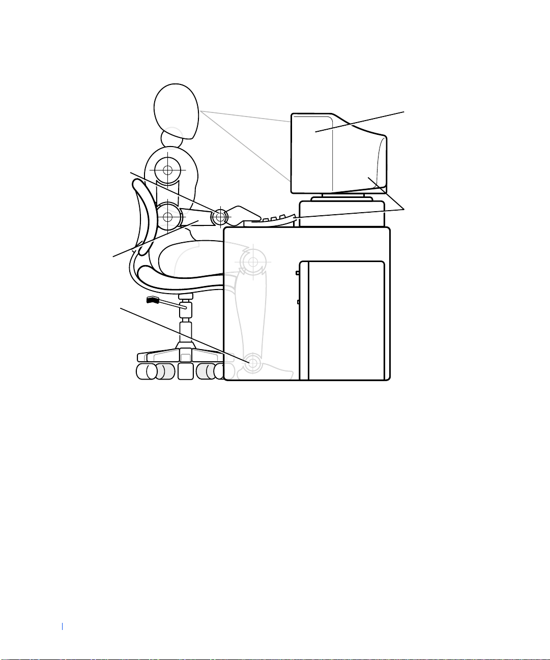
Wrists rel a xed and flat
www.dell.com | support.dell.com
Arms at desk level
Feet flat on the floor
Monitor screen at or
below eye level
Monitor and keyboard
positioned directly in
front of the user
14 Safety Information
Page 15

SECTION 2
About Your Computer
Finding Information and Assistance
Front View of Your Co mp u te r
Back View of Your Computer
Inside Your Computer
www.dell.com | support.dell.com
Page 16
Finding Information and Assistance
The following table lists the resources that Dell provides as support tools.
Additional resources may be shipped with your computer system.
Resources and Support Tools
Resource Contents Using the Resour ce
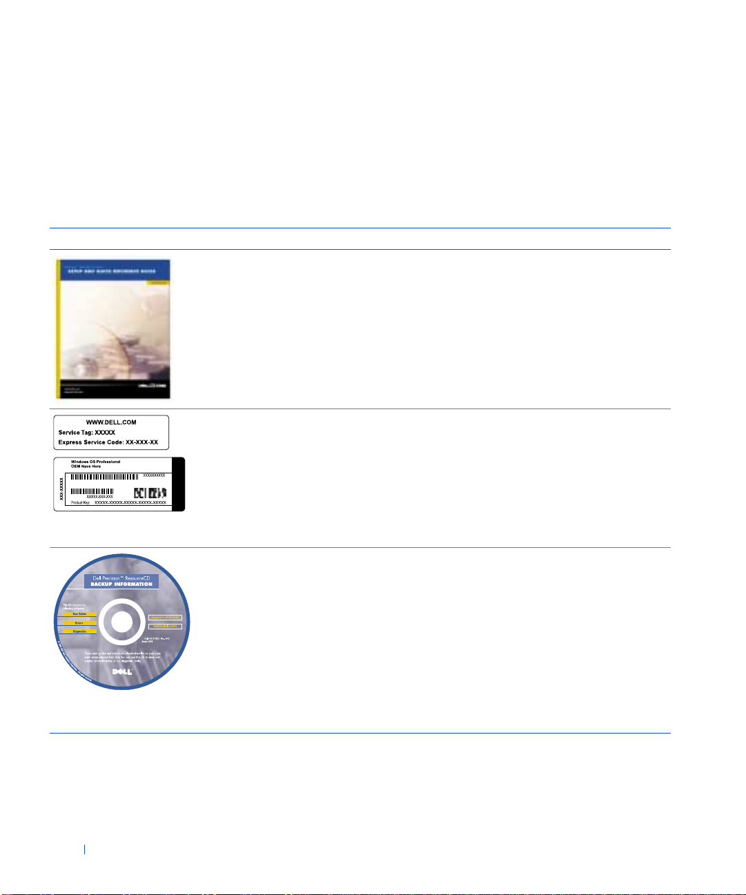
Setup and Quick Reference
Guide
www.dell.com | support.dell.com
• System setup
• Support tools
• Frequently asked questions
• Basic troubleshooting
• Upg rade information
See the Setup and Quick Reference Guide for information
on the following:
• Setting up your computer
• Finding and using support resources
• Diagn osing a problem
• Using tools and utilities
Service and Registration
Labels
• Express Service Code and
Service Tag Number
• Product Key (also called the
Product ID or COA)
The labels located on your
Dell computer.
Dell Precision ResourceCD
•Dell Diagnostics
•Drivers
• Utilities
•Computer and device
documentation
The Express Service Code and Service Tag Number are
unique identifiers for your Dell computer.
You will need the Product Key (or Product ID) number to
complete th e OS setup.
For more information, see the Setup and Quick Reference
Guide.
See the main menu on the ResourceCD that was shipped
with your computer. Use the pull-down menu to make
selections appropriate for your computer . You can perform
the following tasks:
• Diagnose a problem
• Install or reinstall drivers
• Obtain information on your computer and devices
NOTE: User documentation and drivers are already
installed on your computer when shipped from Dell. You
can use this CD to access docume ntation, reinst all drive rs,
or run diagnostic s tools.
16 About Your Computer
Page 17
Resources and Support Tools
Resource Contents Using the Resour ce
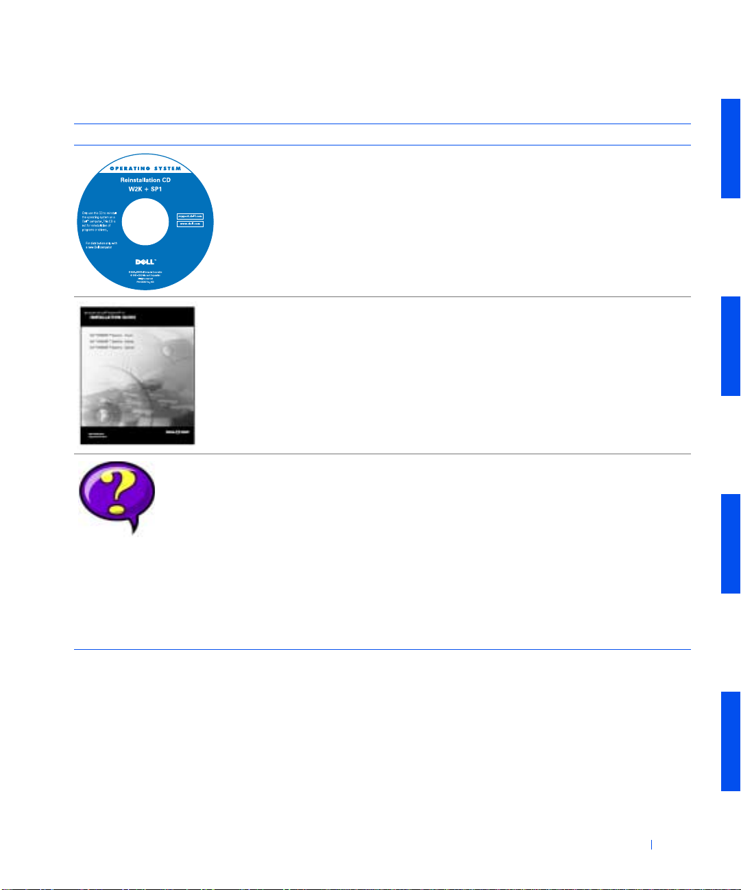
OS CD To reinstall your operat ing system, use the OS C D that
OS installation guide See the OS installation guide for information on
(continued)
was shipped with your computer.
NOTE: The OS CD may not include all the latest drivers
for your computer. If you reinstall your OS, use the
ResourceCD to reinstall drivers for the devices shipped
with your computer.
For more information about reinstalling your OS, see the
OS installation documentation that was shipped with
your computer.
reinstalling and configuring your OS.
User’s Guides
User’s guides for your
computer and devices
Double-click the User’s Guides icon on your desktop to
access the electronic documentation stored on your hard
drive. Obtai n information o n th e fo llowing:
• Using your computer
• Configuring system settings
• Removing and installing parts
• Installing and config uring software
• Diagn osing a problem
• Technical specifications
•Device documentation
• Get ting technical assistan ce
About Your Computer 17
Page 18
Resources and Support Tools
(continued)
Resource Contents Using the Resour ce
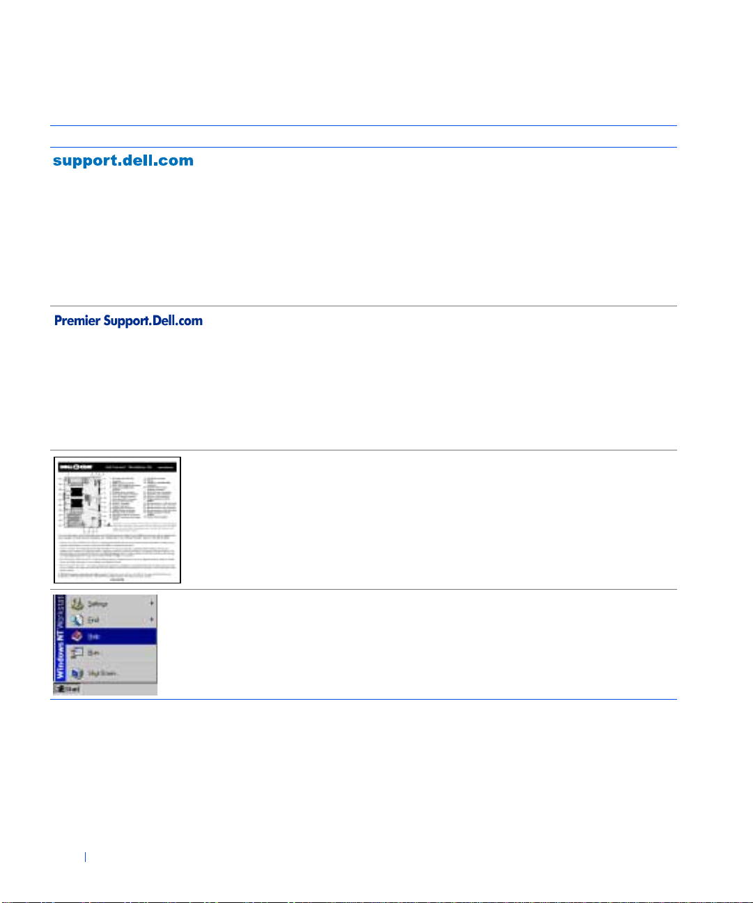
Dell support website
•Ask Dudley
• Dell Knowledge Base
•Dell Documents
•DellTalk
•File downloads
•TechFax
•Vendor links
www.dell.com | support.dell.com
Dell Premier Support website
•Service call status
•Top technical issues by
Go to http://support.dell.com:
• Get help with general usage, installation, and
troubleshooting questions
• Access documentation about your computer and
devices
• Get the latest versions of the drivers for your computer
• Join online discussions with other Dell customers and
Dell technical professionals
• Explore a list of online links to Dell's primary vendors
Go to http://premiersupport.dell.com:
The Dell Premier Support website is customized for
corporate, government, and education customers.
product
• Frequently asked questions
by product number
•Customized service tags
• System configura tion detail
Interior service label A service label affixed to the inside of y o ur computer
cover provides information about working inside your
computer.
OS documentation Click Start and select Help to ob ta in in fo rmat io n on your
18 About Your Computer
OS.
Page 19
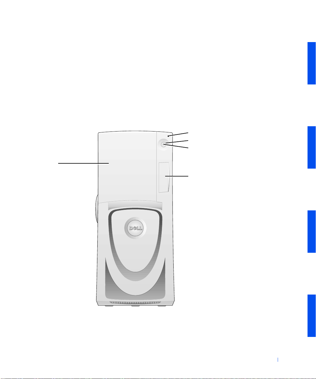
Front View of Your Computer
• Controls and lights
• Connecting devices
The following figures show the controls, lights, and other features on the
front panel of your computer. The drive door can open and fold against the
side of the computer. This allows fully unobstructed use of the externally
accessible drives. See "Opening the Drive Door."
Front View of the Computer
hard-drive access light
power button
power light
externally accessible
drive door
front I/O panel do or
About Your Computer 19
Page 20
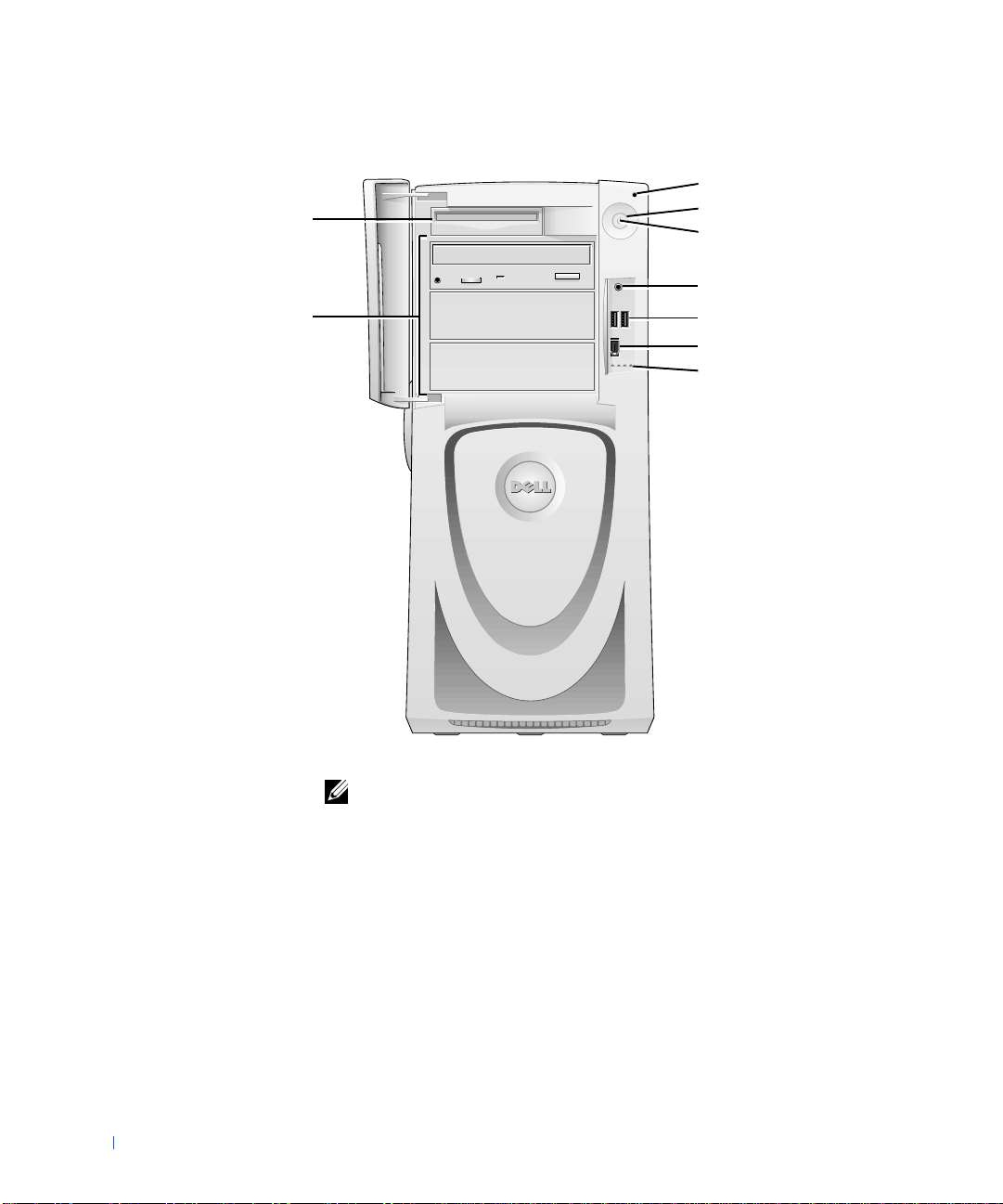
diskette-drive
Front View of the Computer (Doors Open)
hard-drive access light
power button
power light
externally
accessibl e dr i v e s
speaker/headphone jack
Port 2 USB connectors (2)
IEEE 1394 connector
diagnostic lights
www.dell.com | support.dell.com
NOTE: See "System Lights" and "Diagnostic Lights" for descriptions of light
codes and operation s .
20 About Your Computer
Page 21
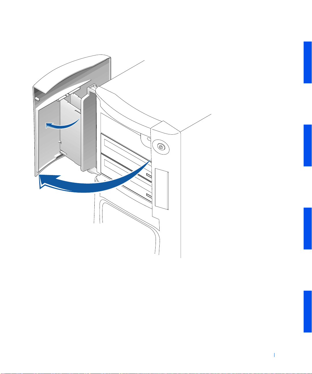
Opening the Drive Door
Controls and Lights
• Power button — controls the computer's AC input power. See the
following table for power button functions on computers running
Microsoft
®
Windows® or WindowsNT®.
About Your Computer 21
Page 22

Power Button Functions
Computer Status Power Button Function
Off Press and r el ease to turn the comp u te r on .
On Press and hold for more than 6 seconds to immediately turn
the computer off.
NOTE: Use this method only if the computer will not shut
down normally.
On (Windows NT) Press and release to attempt an orderly shutdown.
NOTE: This works only if the Dell System Utilities are
www.dell.com | support.dell.com
On (Windows 2000) Press and release to put the computer in the sleep state.
Sleep state
(Windows 2000)
loaded on the computer. Without the utilities, the computer
immediately turns off rather than performs an orderly shut
down.
NOTE: This works depending on how Windows 2000 is
configured. For more information, see "Power
Management."
Pre ss and release to b r in g th e co m p u te r ou t o f the sleep
state. For more information, see "Power Managem ent."
•Power light — illuminates in two colors and blinks or remains solid to
indicate different states.
• Diskette-drive access light — illuminates when the drive is reading
data from, or writing data to, a diskette. Wait until this light turns off
before you re mov e a d iskette from th e drive.
22 About Your Computer
• Hard-drive access light — illuminates when a hard drive is reading data
from, or writing data to, the drive.
• Diagnostic lights — a series of lights that can help you diagnose a
problem with your computer.
Connecting Devices
When you connect external devices to your computer's back panel, follow
these guidelines:
• Check the documentation that accompanied the device for specific
installation and configuration instructions.
Page 23

F or exa mple, you must connect most devices to a particular I/O port or
connector to operate properly. Also, external devices like a printer
usually require you to load device drivers before they will work.
• When connecting a USB mouse or keyboard, ensure that you connect
to one of the Port 1 USB connectors on the back of the computer.
• Always attach external devices while your computer is turned off. Then
turn on the computer before turning on any external devices, unless
the documentation for the device specifies otherwise.
NOTICE: Before disconnecting a device from the computer , wait 10 to 20
seconds aft er turning off the computer to avoid possible damage to the system
board.
Speaker/Headphone Jack
Used to connect computer speakers, headphones, or other audio output
devices. This jack is amplified to support headphones.
IEEE 1394 (FireWire) Connector
Used to attach high-speed serial multimedia devices. For more information,
see "IEEE 1394 (FireWire)."
USB Connectors
Used to attach USB-compliant devices such as pr inters and speak ers to your
computer.
NOTE: When connecting a USB mouse or keyboard, ensure that you connect
to one of the Port 1 USB connectors on the back of the computer.
NOTICE: USB devices do not operate with Microsoft Windows NT.
About Your Computer 23
Page 24
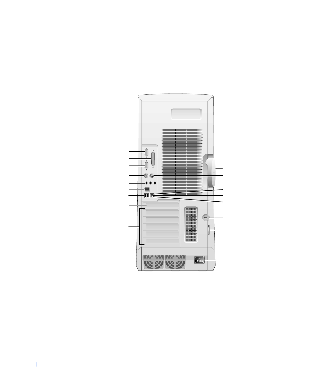
Back View of Your Computer
The following figure shows the connectors, lights, and other features on the
back of your computer.
Back-Panel Features
www.dell.com | support.dell.com
serial port 1 connector
parallel port connector
serial port 2 connector
PS/2 keyboard connector
audio connectors
IEEE 1394 connector
Port 1 USB connectors (2)
AGP expansion slot
PCI expansion slots (5)
cover release latch
PS/2 mouse connector
network activity light
network adapt e r
network link integrity light
security cable slot
padlock ring
24 About Your Computer
AC power connector
Connecting Devices
When you connect external devices to your computer's back panel, follow
these guidelines:
• Check the documentation that accompanied the device for specific
installation and configuration instructions.
Page 25

F or exa mple, you must connect most devices to a particular I/O port or
connector to operate properly. Also, external devices like a printer
usually require you to load device drivers before they will work.
• When connecting a USB mouse or keyboard, ensure that you connect
to one of the Port 1 USB connectors on the back of the computer.
• Always attach external devices while your computer is turned off. Then
turn on the computer before turning on any external devices, unless
the documentation for the device specifies otherwise.
NOTICE: Before disconnecting a device from the computer , wait 10 to 20
seconds aft er turning off the computer to avoid possible damage to the system
board.
Serial Port Connectors
Default serial port designations: COM1 for port 1 and COM2 for port 2.
You can reassign the serial port's designation in system setup if you add an
expansion card containing a serial port using this designation.
If you set the computer’s serial ports to Auto in system setup and add an
expansion card containing a serial port configured to a specific designation,
the computer automatically maps (assigns) the in tegrated ports to the
appropriate COM setting as necessary.
Before you add a card with a serial port, ch e ck the docume ntation that
accompanied your software to ensure that the software can be mapped to
the new COM port designation.
Parallel Port Connector
Used to connect printers. Default parallel port designation: LPT1.
NOTE: The integrated parallel port is automatically disabled if the computer
detects an installed expansion card containing a parallel port configured to the
same address as specified in the Parallel Port option in system setup.
Audio Connectors
The audio controller provides the following connectors:
• Microphone jack—used to connect a standard computer microphone.
About Your Computer 25
Page 26

• Speaker/headphone jack—used to connect computer speakers,
headphones, or other audio output devices. This jack is amplified to
support headphones.
• Line-in jack—used to connect record/playback devi ces such as cassette
players, CD players, and VCRs.
PS/2 Mouse Connector
Attach the PS/2 mouse cable to the 6-pin mouse connector on the back
panel. If your computer uses Microsoft
®
Windows®, Dell installed the
necessary mouse drivers on your hard drive.
www.dell.com | support.dell.com
NOTE: This connector is similar to the keyboard connector. Ensure that you
correctly identify the mouse connector befo re you connect the device.
NOTE: Do not attempt to operate a PS/2 mouse and a USB mouse
simultaneously.
PS/2 Keyboard Connector
Attach the PS/2 keyboard cable to the 6-pin keyboard connector on the back
panel.
NOTE: This connector is similar to the mouse connector. Ensure that you
correctly identify the keyboard connector before you connect the device.
IEEE 1394 (FireWire) Connector
Used to attach high-speed serial multimedia device s. For more information,
see "IEEE 1394 (FireWire)."
USB Connectors
Used to attach USB-compliant devices such as keyboards, mice, printers,
and speakers to your computer.
NOTE: When connecting a USB mouse or keyboard, ensure that you connect
to one of the Port 1 USB connectors on the back of the computer.
NOTE: Do not attempt to operate a PS/2 mouse and a USB mouse
simultaneously.
NOTICE: USB devices do not operate with Microsoft Windows NT
®
.
26 About Your Computer
Network Adapter
The network adapter has the following lights:
Page 27

• A yellow network activity light flashes when the computer is
transmitting or receiving network data. (A high volume of network
traffic may make this light appear to be in a steady "on" state.)
• A dual-colored network link and speed light, which is green when a
good connection exists between a 10-Mbps network and the computer,
or is orange when a good connection exists between a 100-Mbps
network and the computer. When the light is off, the computer is not
detecting a physical connection to the network.
The network controller includes a Remote Wake Up feature. For more
information, see "Network Operations" and "Power Management."
NOTICE: Do not connect a modem cable to the network adapter. Voltage
from telephone communications can damage the network adapter.
Network Connection Requirements
Press one end of the UTP Ethernet cable into the network adapter on your
computer until the cable snaps securely into place. Connect the other end
to an RJ45 jack wall plate or to an RJ45 port on a UTP concentrator or hub,
depending on your network configuration.
Dell recommends the use of Category 5 wiring and connectors for our
customers' networks.
NOTE: Verify the type of network device to which you are connecting the
computer. A hub typically operates at 10-Mbps. A switch can operate at 10- or
100-Mbps. Ensure th at the network adapter is configured for the appropriate
speed. See network adapter diagnostics and configuration utility on Dell
Diagnostics.
About Your Computer 27
Page 28

Inside Your Computer
•System cables
•System board components
• Front panel components
The following figure shows the computer with the cover open.
NOTE: User service access points are color-coded green.
www.dell.com | support.dell.com
28 About Your Computer
Page 29
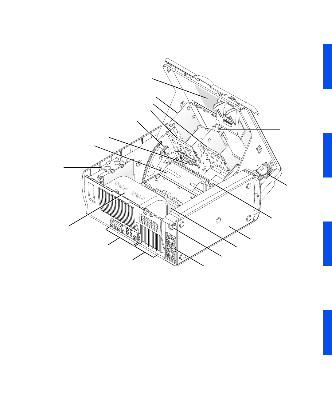
Inside the Computer
externally accessible-drive bracket
chassis intrusion switch
front panel
cable retainer
memory riser board
retention bracket
(if needed)
interior service label
diskette drive bracket
hard-drive bracket
AGP card
brace
speaker
microprocessor
airflow shroud
I/O panel connectors
expansion-card slots
power supply airflow vents
System Cables
The following illustration shows all potential connectivity throughout the
computer. Connectivity is provided by the system board and front panel.
expansion-card
cooling fan
power supply
system board
AC power receptacle
About Your Computer 29
Page 30
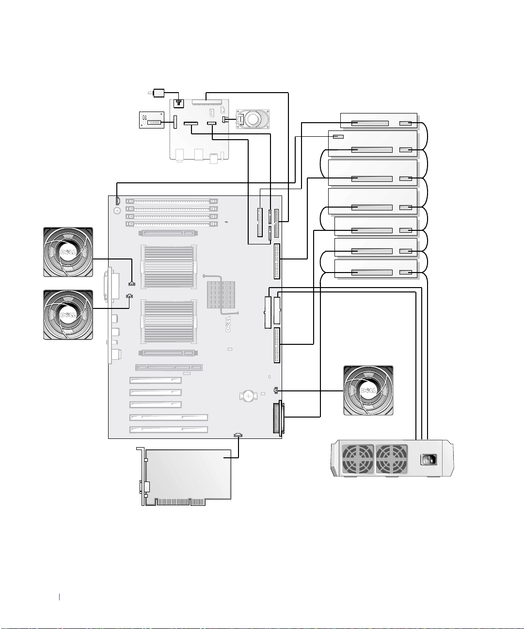
chassis intrusion switch
microprocessor 0
www.dell.com | support.dell.com
fan
control panel
System Cabling
front panel
speaker
drives
diskette
externally
accessible
EIDE
bootable
EIDE
and/or
LVD SCSI
microprocessor 1
fan
30 About Your Computer
expansion car d
fan
power suppl y
telephony/modem
expansion card
Page 31

NOTE: The co ntro l panel sho wn in "System Ca bling" is mounted to the front of
the chassis frame. It controls the power button, power light, and hard-drive
access light. The chassis intrusion switch and the chassis speaker are mounted
inside the computer cover. For more information on these components, see the
Service Manual
.
System Board Components
The following figure shows the principal connectors and components on the
system board.
About Your Computer 31
Page 32

System Board Components
RIMM sockets (4)
CD audio input
connector
system board speaker
VRM 0 connector
microprocessor 0
with heat sink
microprocessor 0
fan connector
www.dell.com | support.dell.com
parallel and serial (2)
port connectors
microprocessor 1
fan connector
PS/2 keyboard and
mouse connectors
audio connectors
IEEE 1394 connector
microprocessor 1
with heat sink
network and Port 1
USB (2) connectors
VRM 1 connector
32-bit PCI expansion
card connectors (3)
64-bit PCI expansion
card connectors (2)
suspend-to-RAM light
diskette-drive
connector
front panel
audio connector
front I/O panel
connector
front panel IEEE
1394 connector
secondary EIDE
connector
chip set with
heat sink
power 1 connector
power 2 connector
primary EIDE
connector
password jumper
AGP Pro expansion
card connector
standby power
light
expansion card
fan connector
real-time clock
reset jumper
LVD SCSI
connector
32 About Your Computer
battery socket
telephony connector
auxiliary drive access light connector
Page 33

System Board Labels
The following table lists the labels for connectors and components on the
system board, and briefly describes the function of each.
System-Board Labels
Connector or Component L abe l
1394 IEEE 1394 connector
AGP AGP Pro expansion-card connector
AUDIO Audio connectors
AUX_LED Auxiliary drive acce ss light connector
BATTERY Battery socket
CD_IN CD audio input connector
CPU_0 Microprocessor 0 with heat sink
CPU_1 Microprocessor 1 with heat sink
DISKETTE Diskette-drive connector
FAN_CCAG Expansion card fan connector
FAN_P0 Microprocessor 0 fan connector
FAN_P1 Microprocessor 1 fan connector
FPAUDIO Front panel audio co nnector
FRONT1394 Front panel IEEE 1394 connector
IDE1 Primary EIDE connector
IDE2 Secondary EIDE connector
KYBD_MOUSE PS/2 keyboard and mouse connectors
PANEL Front I/O panel connector
PARALLEL_SERIAL Parallel and serial (2) port connectors
PCIn PCI expansion-card connector
POWER1 Power 1 connector
POWER2 Power 2 connector
PSWD Password jumper
RIMM_n RIMM socket
RTCRST Real-time clock reset jumper
About Your Computer 33
Page 34

System-Board Labels
Connector or Component L abel
SCSI LVD SCSI connector
SPKR System board speaker
STANDBY_LED Standby power light
STR_LED Suspend-to-RAM light
TAPI/MODEM Telephony (TAPI) connec t o r
USB_NIC Network and Port 1 USB (2) connectors
VRM_0 VRM 0 connector
www.dell.com | support.dell.com
VRM_1 VRM 1 connector
(continued)
Front Pane l Compone nts
The front panel provides connectivity for the computer front I/O panel as
well as several components located inside the chassis. The following figure
shows the principal connectors on the front panel.
front panel audio connector
speaker/headphone jack
Port 2 USB connectors (2)
IEEE 1394 connector
diagnostic lights
front panel IEEE 1394 connector
34 About Your Computer
control panel connecto r
chassis intrusion
switch connector
system board
connector
chassis speaker connector
Page 35

NOTE: The control panel is mounted to the front of the chassis frame. It
controls the power button, power light, and hard-drive access light. The chassis
intrusion switch and the chassis speaker are mounte d inside the computer
cover. For more information on these components, see the
Service Manual
Front Panel Labels
The following table lists the labels for connectors on the front panel, and
briefly describes the function of each.
Front Panel Labels
Connector Label
1394 System board IEEE 1394 connector
1394_FNT IEEE 1394 connector
AUDIO System board audio connector
CTRL_PNL Control panel connector
DIAGLED Diagnostic lights
EXT_SPKR Chassis speaker connector
FNT_PNL System board connector
HP_OUT speaker/headphone jack
INTRUDER Chassis intrusion switch connector
USB_FNT Port 2 USB connectors (2)
.
About Your Computer 35
Page 36

www.dell.com | support.dell.com
36 About Your Computer
Page 37

SECTION 3
Advanced Features
System Settings
Manageability
Security
Password Protection
Jumper Settings
Installing and Configur ing Software
TAPI
IEEE 1394 (FireWire)
Power Management
Dell System Utilities
www.dell.com | support.dell.com
Page 38

System Settings
• Entering system setup
• System setup screens
• System setu p navigation keys
• Changing the boot sequence
• Network operations
• Integrated devices
www.dell.com | support.dell.com
Each time you start your computer, it compares the installed hardware with
the system configuration information stored in NVRAM. If the computer
detects a discrepancy, it generates an error message for each incorrect
configuration setting.
You can use system settings as follows:
• To set user-selectable options such as date and time or system
password
• To set the current configuration information such as the amount of
memory or type of hard drive installed
You can view the current settings at any time. Dell recommends that you
record the information for future reference. If you have a line printer
connected to the parallel port on your computer, you can print the system
setup screens by pressing <Print Screen>.
Before you use system setup, you need to know the kind of diskette drive(s)
and hard drive(s) installed in your computer. If you are unsure of this
information, see the Manufacturing Test Report that came with your
computer and is located in the Dell Accessories folder.
Entering System Setup
1 Turn on your computer.
38 Advanced Features
If your computer is already on, restart it.
2 When F2 = Setup appear s in the upper-right corner of the screen,
press <F2>.
Page 39

The System Setup menu appears.
If you wait too long and your operating system begins to load into memory,
let the computer complete the load operation; then restart the comput er and
try again.
NOTE: To ensure an orderly system shutdown, consult the documentation that
accompanied your opera ting system.
System Setup Screens
The system setup screens display the current configuration information for
your computer. Information on the screen is organized into four areas:
• Title — the box at the top of all screens that lists the computer system
name.
• Computer data — two boxes below the title box that display your
microprocessor, L2 cache, service tag number, and the version number
of the BIOS.
• Options — a scrollable box listing options that define the
configuration of your computer, including installed hardware, power
conservation, and security features.
Fields to the right of the option titles contain settings or values. Those
that you can change appear bright on the screen. Those that you
cannot change (because they are set by the computer) appear less
bright. Wh en
<Enter> to access a pop-up menu of additional options.
• Key functions — a line of boxes across the bottom of all screens that
lists keys and their functions within system setup.
<Enter> appears to the right of an option title, press
• Help — press <F1> for information in the currently highlighted
option.
System Setup Navigation Keys
The following table lists the keys you use to view or change information in
system setup and to exit setup.
Advanced Features 39
Page 40

System Setup Navigation Keys
Key(s) Action
or
or
Moves to the next field.
Moves to the previous field.
www.dell.com | support.dell.com
spacebar or In the selected field's pop-up options menu, cycles through
or
or
or
NOTE: F or most of the options, any changes you make are recorded but do not
take effect until the next time you turn on the computer. For a few options (as
noted in the help area), the changes take effect immediately.
Cycles through the options in a field. In many fields, you can
also type the appropriate value. To access a field’s pop-up
options menu, press <Enter>.
Scrolls through help information.
Accesses the selected field's pop-up option s men u.
the options in a field.
Exits system setup without rebooting the computer and
returns the computer to th e bo ot routine.
Exits system setup and reboots the computer , implementing
any changes you have made.
Resets the selected option to its default setting.
40 Advanced Features
Changing the Boot Sequence
The boot sequence allows you to specify the order of the devices from which
the system attempts to boot.
1 Press <Ente r> to access the Boot Sequence option's pop-up menu.
Page 41

NOTE: Write down your current boot sequence in case you want to
restore it.
Press the up- and down-arrow keys to move through the list of devices.
2
3 Press the spacebar to enable or disable a device (enabled devices
appear with a check mark).
4 Press plus (+) or minus (–) to move a selected device up or down the
list.
Option settings:
• Diskette Drive A: — The system attempts to boot from the dis kette
drive. If the system finds a diskette in the drive that is not bootable, an
error message appears. If no diskette is in the drive, the system
attempts to boot from the next device in the list.
• Hard Drive — The system attempts to boot from the primary hard
drive. If the system does not find an operating system on the drive, it
attempts to boot from the next device in the list.
• CD Drive — The system attempts to boot f rom the CD drive. If the
system does not find a CD in the drive or if there is not an operating
system on the CD, the system attempts to boot from the next device
in the list.
• MBA — The system prompts you to press <Ctrl><Alt><b> at the
Dell logo screen during boot . A me nu appe ars t hat allo ws you to select
a method for booting from a network server. If a boot routine is not
available from the network server, the system attempts to boot from
the next device in the list.
Network Operations
For proper network operations, several options in system setup must be
configured properly:
• Network interface controller
• Boot sequence
• Remote wake up
For information on the relationship of the various option settings, see
"Network Configurations."
Advanced Features 41
Page 42

Network Interface Controller
This option, under the Integrated Devices menu, enables or disables the
integrated network adapter. This field also allows you to enable MBA
support.
Option settings:
• On — The integrated network adapter is enabled.
• On w/ MBA — The integrated network adapter is enabled with MBA
support.
• Off — The integrated network adapter is disabled.
www.dell.com | support.dell.com
NOTE: You must restar t the computer before Network Interface Controller
option settings will take effect.
Boot Sequence
The Boot Sequence MBA option setting allows yo u to s pe c ify a m e tho d f o r
booting from a network server.
Remote Wake Up
Remote Wake Up provides the ability either to remotely wa ke a computer
from a low-power sleep state or to remotely start up a computer that is
turned off but connected to a power source.
42 Advanced Features
Option settings:
• On — The computer will start up when the appropriate signal is
received by the network adapter (WOL) or modem (WOR).
• On w/ Boot to NIC — When the network adapter or modem receives
the appropriate signal, the computer attempts to boot from a network
server. If a boot routine is not available from the network server, the
computer attempts to boot from the devices specified in the Boot
Sequence.
• Off — The computer will not start up remotely.
Network Configurations
The system setup options for network operations work together for
particular functions. The following table describes the relationship of the
various option settings:
Page 43

Network Option Settings
Network Interface
Controller
Off MBA is not available Not available • The computer attempts to boot from the devices
On MBA is not available Available • The computer attempts to boot from the devices
On w/ MBA MBA is set as first
NOTE: You must restart the computer before Network Interface Controller
option settings will take effect.
Boot Sequen ce Remote Wake Up Function
specified in the Boot Sequence.
• The co mputer cannot be remotely started.
specified in the Boot Sequence.
• The computer can be remotely started by WOL
and/or WOR.
Available • The computer prompts you to press
boot device
<Ctrl><Alt><b> during start up, allowing
you to select a network boot method.
• The computer can be remotely started by WOL
and/or WOR.
Integrat ed D evices
You computer has several integrated devices. For these devices to be
accessible to the OS, the corresponding options in system setup must be
configured properly.
To enable or disable an integrated device, enter system setup, select
Integrated Devices and change the setting for the appropriate device to On
or Off:
• Sound
•SCSI
• IEEE 1394
•PS/2 mouse
•USB
Advanced Features 43
Page 44

Manageability
The following systems management applications are optional and can be
included on your computer when you order it. You can also download the
applications from the Dell support website and install them on your
computer. See "Downloading Systems Management Utilities" for more
information.
•Dell OpenManage™ IT Assistant
• Dell OpenManage Client Instrumentation
www.dell.com | support.dell.com
Dell OpenManage IT Assistant
Dell OpenManage IT Assistant is the premier Dell™ systems management
application for configuring, managing, and monitoring computers and other
devices on a corporate network. IT Assistant employs the latest remote
management technology to provide asset management, configuration
management, event (alert) management, and security management for
systems equipped with industry-standard management software. Software
of this type is called system management instrumentation.
IT Assistant supports instrumentation that conforms to the following
industry standards:
•SNMP
•DMI
•CIM
The instrumentation available for your computer is Dell OpenManage
Client Instrumentation, which is based on DMI and CIM. For more
information on IT Assistant, see the Dell OpenManage IT As sistant User’s
Guide available on the Dell
Management Utilities" for more information.
support website. See "Downloading Systems
Dell OpenManage Client Instrumentation
Dell OpenManage Client Instrumentation is software that enables remote
management application programs such as IT Assistant to do the following:
44 Advanced Features
Page 45

• Access information about your computer , such as how many processors
it has and what operating system it is running
• Monitor the status of your computer, such as listening for thermal
alerts from temperature probes or hard drive failure alerts from storage
devices
• Change the state of your computer, such as updating its BIOS or
shutting it down remotely
Dell OpenManage Client Instrumentation can be installed your computer,
which, when set up on a network with IT Assistant, is called a managed
system. For more information about Dell OpenManage Client
Instrumentation, see the Dell OpenManage Client Instrumentation User’s
Guide available on the Dell suppo r t website. See "Downloading Systems
Management Utilities" for more information.
Downloading S y s te m s Management Ut il ities
The systems management utilities are available for download from the Dell
support website. See "Finding Information and Assistance" for more
information.
1 Go to http://support.dell.com.
If this is your first time to use this website, complete the one-time
registration.
2 Click Downloads for Your Dell.
3 Enter the Service Tag Number for the computer or select the
appropriate Dell system.
4 Select the appropriate OS and language for the computer.
5 Select Systems Management for the download category.
6 Click Go.
7 Follow the instructions on screen to download and install the utilities.
Advanced Features 45
Page 46

Security
The computer provides the following methods to physically secure it:
• Chassis intrusion detection
• Security cable slot and padlock ring
Chassis Intrusion Detection
The chassis intrusion monitor can detect whether the computer is opened.
The Chassis Intrusion option in syst e m setup displays the status of the
monitor.
www.dell.com | support.dell.com
1 Enter system setup.
2 Press the down-arrow key to move to the System Security option.
3 Press <Ente r> to access the System Security option's pop-up menu.
4 Press the down-arrow key to move to the Chassis Intrusion option.
5 Press the spacebar to select an option setting.
Option settings:
• Enabled — When the computer cover is opened, a DMI event is
generated, the setting changes to Detected, and the following message
appears at the next system start-up:
46 Advanced Features
Alert! Cover was previously removed.
To reset the Detected setting, enter system setup. In the Chassis
Intrusion option, p ress the left- or right-arrow key to select Reset, and
then choose Enabled, Enabled-Silent, or Disabled.
• Enabled-Silent (the default) — When the computer cover is opened,
a DMI event is generated and the setting changes to Detected, but the
alert message does not appear at the next system start-up.
• Disabled — No intrusion monitoring occurs and no messages appear.
NOTE: When the setup password is enabled, you must know the setup
password before you can reset the Chassis Intrusion option.
Page 47

Security Cable Slot and Pad lock Ring
The computer has features that allow you to attach commercially available
antitheft devices:
• Padlock ring—to prevent unauthorized access to the interior of your
computer , install a standard padlock through the rings in the computer
chassis and cover.
• Security cable slot—to prevent unauthorized removal of your
computer, loop the galvanized security cable around an immovable
object, insert the attached locking device into the security cable slot
on the back of your computer, and lock the device with the key
provided.
To locate the computer security features, see "Back-Panel Features" and
"Opening the Computer Cover."
NOTE: Before you purchase an antitheft device, ensure that it works with your
computer.
Advanced Features 47
Page 48

Password Protection
The computer provides the following types of password protec tion:
•System password
•Setup password
System Password
• Assigning a system password
• Using your system password
www.dell.com | support.dell.com
• Deleting or changing an existing system password
System passwords allow only those who know the password to have full use
of the computer. Your computer does not have the system password feature
enabled when you receive it.
NOTICE: Although passwords provide security for the data on your computer,
they are not foolproof. If your data requires more security, it is your
responsibility to obtain and use additional forms of protection, such as data
encryption pro grams.
NOTICE: If you leave your computer running an d unattended without having
a system password assig ned, or if you leave your computer unlocked so that
someone can disable the password by changing a jumper setting, anyone can
access the data stored on your hard drive.
System Password settings in system setup:
NOTE: You cannot change or enter a new system password if either Enabled
or Disabled is displayed. You can only assign a system password when System
Password is set to Not Enabled.
• Enabled — a system password is assigned
• Disabled — system password feature is disabled by a jumper setting on
the system board
• Not Enabled — no system password is assigned and the password
jumper on the system board is in the enabled position (its default)
48 Advanced Features
Assigning a System Password
1 Verify that Password Status is set to Unlocked.
Page 49

2 Highlight System Password and then press the left- or right-arrow key.
The option heading changes to Enter Password, followed by an empty
32-character field in square brackets.
3 Type your new system password.
You can use up to 32 characters.
As you press each character key (or the spacebar for a blank space), a
placeholder appears in the field. The password assignment operation
recognizes keys by their location on the keyboard, without
distinguishing between lowercase and uppercase characters. For
example, if you have an M in your password, the computer recognizes
either M or m as correct.
Certain key combinations are not valid. If you enter one of these
combinations, the speaker emits a beep.
To erase a character when entering your password, press <Backspace>
or the left-arrow key.
NOTE: To escape from the field without assigning a system password,
press <Tab> or the <Shift><Tab> combination to move to another
field, or press <Esc> at any time before completing step 5.
4 Press <Enter>.
If the new system password is less than 32 characters, the whole field
fills with placeholders. Then the option heading changes to Verify
Password, followed by another empty 32-character field in square
brackets.
5 To confirm your password, type it a second time and press <Enter>.
The password setting changes to Enabled. Your system password is
now set; you can exit system setup and begin using your computer.
Password protection takes effect when yo u restart the computer.
Using Your System Password
When you start up the computer, the following prompt appears on the
screen when Password Status is set to Unlocked:
Type in the password and
- press <ENTER> to leave password security enabled.
- press <CTRL><ENTER> to disable password security.
Enter password:
Advanced Features 49
Page 50

If Password Status is set to Locked, the following prompt appears:
Type the password and press <Enter>.
NOTE: If you have assigned a setup password, the computer accepts your
setup password as an alternate system password.
If you enter a wrong or incomplete system password, the following message
appears on the screen:
** Incorrect password. **
Enter password:
If you again enter an incorrect or incomplete system password, the same
www.dell.com | support.dell.com
message appears on the screen. The third and subsequent times you en ter
an incorrect or incomplete system password, the computer displays the
following message:
** Incorrect password. **
Number of unsuccessful password attempts: 3
System halted! Must power down.
Even after your computer is turned off and on, the previous message is
displayed each time an incorrect or incomplete system password is entered.
NOTE: To further protect your computer from unauthorize d changes, you can
use the Password Status system setup option in conjunction with the System
Password and Setup Password options.
50 Advanced Features
Deleting or Changing an Existing System Password
1 Enter system setup, and verify that Password Status is set to Unlocked.
2 Reboot your comput e r t o forc e it t o prom pt y o u fo r a sy st em password.
3 When prompted, type the system password.
4 Press <Ctrl><Enter> to disable the existing system password,
instead of pressing <Enter> to continue with the normal operation of
your computer.
5 Confirm that Not Enabled is displayed for the System Password
option.
If Not Enabled appears in the System Password option, the system
password has been deleted. If you want to assign a new password,
continue to step 6. If Not Enabled is not displayed for the System
Page 51

Password option, press <Alt><B> to reboot the computer, and then
repeat steps 3 through 5.
6 To assign a new password, follow the proc edure in "Assigning a System
Password."
Setup Password
• Assigning a setup password
• Operating your computer with a setup password enabled
• Deleting or changing an existing setup password
• Disabling system and setu p passwords
Setup passwords allow only those who know the password to have full use of
system setup. Your computer does not have the setup password feature
enabled when you receive it.
Setup Password options in system setup:
• Enabled — does not allow assignment of setup passwords; users must
enter a setup password to make changes to system setup
• Not Enabled — allows assignment of setup passwords; password
feature is enabled but no password is assigned
Assigning a Setup Password
1 Enter system setup, and verify that Setup Pas sword is set to Not
Enabled.
2 Highlight Setup Password and press the left- or right-arrow key.
The computer prompts you to enter and verify the password. If a
character is illegal for password use, the computer emits a beep.
3 Type in and then verify the password.
After you verify the password, the Setup Password setting changes to
Enabled. The next time you attempt to enter system setup, the
computer prompts you for the setup password.
NOTE: The setup password can be the same as the system password.
Advanced Features 51
Page 52

NOTE: If the two passwords are different, the setup password can be used as
an alternate system password. However, the system password cannot be used in
place of the setup password.
A change to Setup Password becomes effective immediately (rebooting the
computer is not required).
Operating Your Computer With a Setup Password Enabled
When you start system setup, the Setup Password option is highlighted,
prompting you to type the password.
If you do not enter the correct password, the computer lets you view, but
www.dell.com | support.dell.com
not modify, system setup options.
NOTE: To further protect your computer from unauthorize d changes, you can
use the Password Status system setup option in conjunction with the System
Password and Setup Password options.
Deleting or Changing an Existing Setup Password
To change an existing setup password, you must know the setup password.
1 Enter system setup.
2 If you have already assigned a setup password, type it at the prompt.
3 Highlight Setup Password and press the left- or right-arrow key to
delete the existing setup password.
52 Advanced Features
The setting changes to Not Enabled.
4 If you want to assign a new setup password, perform the steps in
"Assigning a Setup Password."
Disabling System and Setup Passwords
NOTICE: This process erases both the system and setup passwords.
CAUTION: Before you perform this procedure, see "Safety First—
For You and Yo ur Com puter."
NOTICE: Before disconnecting a device from the computer, wait 10 to 20
seconds after disconnecting the computer from its electrical outlet. Before
removing a component from the system board, verify that the stan dby power
light on the system boa rd has turned off . To locate this light, see "System Board
Components" or "Interior Service Label."
Page 53

1 Turn off the computer and devices, disconnect them from their
electrical outlets, and wait 10 to 20 seconds.
2 Lay the computer on its right side.
3 Open the computer cover.
4 Remove the jumper plug from the PSWD jumper to disable the
password feature.
See "Jumper Settings" to locate the password jumper (labeled
"PSWD") on the system board.
5 Close the computer cover.
6 Stand the computer upright.
7 Reconnect the computer and devices to their electrical outlets , and
turn them on.
The existing password(s) are erased.
NOTE: If enabled, the Chassis Intrusion option will cause the following
message to be displaye d at the next system start-up:
ALERT! Cover was previously removed.
Proceed to step 9 if you want to assign a new password.
8
NOTE: Before you assign a new system and/or setup password, you must
install the PSWD jumper plug to reenable the password feature.
Turn off the computer and devices, disconnect them from their
9
electrical outlets, and wait 10 to 20 seconds.
10 Lay the comp uter on i ts rig ht side.
11 Open the computer cover.
12 Install the PSWD jumper plug.
13 Close the comput er cover.
14 Stand the comput er u pright.
15 Reconnect the computer and devices to their electrical outlets, and
turn them on.
Turning on your computer with the PSWD jumper installed reenables
the password feature. When you enter system setup, both password
Advanced Features 53
Page 54

options appear as Not Enabled, meaning that the password feature is
enabled but that no password is assigned.
16 Assign a new system and/or setup password.
www.dell.com | support.dell.com
54 Advanced Features
Page 55

Jumper Settings
The following figure show s t he locat ion of t he jumper s on the s yst em board.
System Board Jumpers
PSWD
RTCRST
NOTICE: Before changing a jumper setting, verify that the standby power
light on the system board has turned off. Otherwise, damage to your computer
or unpredictable results may occur. To locate this light, see "System Board
Components" or the interior service label.
To change a jumper setting, pull the plug off its pin(s) and carefully fit it
down onto the pin(s) indicated.
The following table lists the system board jumpers and their settings.
System-Board Jumper Settings
Jumper Setting Description
PSWD (default) Password features are enabled.
Password features are disabled.
RTCRST Real-time clock reset. Can be used for
troubleshooting. See "Reset Corrupted BIOS
Settings."
jumpered unjumpered
Advanced Features 55
Page 56

Installing and Configuring Software
See "Finding Information and Assistance" for a list of software resources
available to you from Dell, including drivers, utilities, documentation, and
operating system backups. Before installing software that was not provided
with your Dell computer, check the software for viruses with virus-scanning
software. Viruses can quickly use all availab le system me mory, damage o r
destroy data stored on the hard drive, and permanently affect the
performance of the programs they infect. Several commercial virusscanning programs are available for purchase, and many websites distribute
virus-scanning programs that you can download.
www.dell.com | support.dell.com
Before you install a program, read its documentation to learn how the
program works, what hardware it requires, and what its defaults are. A
program usually includes installation instructions in its accompanying
documentation and a software installation routine on its program
diskette(s) or CD(s).
The software installation routine assists you in transferring the appropriate
program files to your computer's hard drive. Installation instructions may
provide details about how to configure your operating system to successfully
run the program. Always read the installation instructions before running a
program's installation routine.
When you run the installation routine, be prepared to respond to prompts
for information about how your computer's operating system is configured,
what type of computer you have, and what peripherals are connected to
your computer.
NOTE: If you experience any problems while installing or operating your
software, see "Software Problems."
56 Advanced Features
Page 57

TAPI
The TAPI features of your computer enable Microsoft® Windows®-based
applications to operate with a wide variety of telephony devices, including
voice, data, fax, video, and so forth. TAPI applications require a T API service
provider (TSP), which is a software driver that allows TAPI applications to
communicate with different types of TAPI hardware.
Microsoft Windows provide a TSP called Uni modem, which is a "universal"
modem service provider that supports a wide range of commonly used
modems. For more information on Unimodem, see your Windows
documentation. When using a TAPI device other than a modem, such as a
PBX or a voice processing card, you will need a TSP provided by the
manufacturer of the device.
The TAPI system-board connector uses a 4-pin cable to interface your
internal TAPI-compliant expansion card with the audio system in your
computer. To locate the TAPI system-board connector, see "System Board
Components" or the interior service label. Your computer supports TAPI-
compliant cards using the standard TAPI connector. For example, you can
connect your modem to the TAPI connector and then use your audio
speakers and microphone as a speakerphone. The microphone carries your
voice into the computer and then through the TAPI system board connector
to your modem card. The caller’s voice enters through the modem card to
the T API system board connector and then out to the speakers. You can also
use this configuration to record and play sound files over the phone.
Installing a TAPI Device
CAUTION: Before you perform this procedure, see "Safety First—
For You and Yo ur Com puter."
NOTICE: Before disconnecting a device from the computer , wait 10 to 20
seconds after disconnecting the computer from its electrical outlet. Before
removing a component from th e system board, verify that the standby power
light on the system boa rd has turned off . To locate this light, see "System Board
Components" or the interior service label.
1 Turn off the computer and devices, disconnect them from their
electrical outlets, and wait 10 to 20 seconds.
2 Lay the computer on its right side.
Advanced Features 57
Page 58

3 Open the computer cover.
4 Install the TAPI-compliant expansion card.
See the manufacturer’s documentation for more information.
5 Connect the 4-pin TAPI cable to the TAPI system-board connector.
To locate the TAPI connector on the system board, see "System Board
Components" or the interior service label.
6 Connect the 4-pin TAPI cable to the TAPI expansion-card connector.
To locate the TAPI connector on the expansion card, see the
manufacturer’s documentation.
www.dell.com | support.dell.com
7 Close the computer cover.
8 Stand the computer upright.
9 Reconnect the computer and devices to their electrical outlets, and
turn them on.
NOTE: If enabled, the Chassis Intrusion option will cause the following
message to be displayed at the next system start-up:
ALERT! Cover was previously removed.
10
Install the appropriate TSP for the TAPI device.
See the manufacturer’s documentation and your Windows
documentation for more information.
58 Advanced Features
Installing a TAPI Sound Card
You can install a TAPI-compliant sound card that has a standard TAPI
connector. For example, you can connect your modem to the TAPI sound
card connector and then use the audio capabilities as a speakerphone.
CAUTION: Before you perform this procedure, see "Safety First—
For You and Yo ur Com puter."
NOTICE: Before disconnecting a device from the computer, wait 10 to 20
seconds after disconnecting the computer from its electrical outlet. Before
removing a component from the system board, verify that the stan dby power
light on the system boa rd has turned off . To locate this light, see "System Board
Components" or the interior service label.
1 Turn off the computer and devices, disconnect them from their
electrical outlets, and wait 10 to 20 seconds.
Page 59

2 Lay the computer down on its right side.
3 Open the computer cover.
4 Install the TAPI-compliant expansion card.
See the manufacturer’s documentation for more information.
5 Enter system setup, click Integrated Devices, and change the setting
for Sound to Off.
6 Connect external audio devices to the sound card’s connectors. Do not
connect external audio devices to the microphone,
speaker/headphone, or line-in connectors on the computer back panel
(see "Back-Panel Features").
7 Connect the 4-pin TAPI cable to the TAPI sound-card connector.
To locate the TAPI connector on the sound card, see the
manufacturer’s documentation.
8 Connect the 4-pin TAPI cable to the TAPI expansion-card connector.
To locate the TAPI connector on the expansion card, see the
manufacturer’s documentation.
9 Close the computer cover.
10 Stand the comput er u pright.
11 Reconnect the computer and devices to their electrical outlets, and
turn them on.
NOTE: If enabled, the Chassis Intrusion option will cause the following
message to be displaye d at the next system start-up:
ALERT! Cover was previously removed.
12
Install the appropriate TSP for the TAPI devices.
See the manufacturer’s documentation and your Windows
documentation for more information.
Advanced Features 59
Page 60

IEEE 1394 (FireWire)
FireWire is a high-speed data bus that is defined by IEEE Standard 1394-
1995. This protocol is a scalable, flexible, low-cost digital interface. It can
move large amounts of data between computers and peripheral devices,
using simplified cabling, hot-swapping, and transfer speeds up to 4 00Mbps.
Because of the very high data rates that FireWire can handle, it is ideal for
use with multimedia devices such as digital video cameras and high-speed
hard drives and printers. FireWire speeds the transfer of multimedia data
and large files, enabling a PC to connect directly to digital consumer
products such as camcorders, video tape drives, video disks, high-resolution
www.dell.com | support.dell.com
scanners , and music systems.
Microsoft
that OSs, drivers, and applications work properly with any compliant
hardware. Your computer provides a standard IEEE 1394 connector on both
the front and back panels. See "Front View of the Computer (Doors Open)"
and "Back-Panel Features." This allows you use multiple e xternal IEEE 1394
devices with your computer.
The OHCI standards allow Windows 2000 to suppo rt hard drives, CD and
DVD drives, and other devices through the Serial Bus Protocol (SBP-2)
driver. SCSI class drivers can then use SBP-2 to communicate with IEEE
1394 devices. For example, an IEEE 1394 CD drive can be supported by
SBP-2 and the existing SCSI driver architecture. For more information on
IEEE 1394, OHCI, and the SBP-2 driver, see your Windows documentation.
®
Windo ws® 2000 supports the IEEE 1394 standard, ensuring
60 Advanced Features
Page 61

Power Management
Your computer can be set to use less power when you are not working. You
control the power usage through the OS installed on your computer and
certain option setti n g s in system setup. These periods of reduced power are
called "sleep states":
• Standby. In this sleep state, power is reduced or turned off for most
components, including the cooling fans. However, system memory
remains active .
®
This state is not supported by Windows NT
NOTE: All components installed in the computer must support this
feature and have the appropriate drivers lo aded to enter standby. For
more information, see th e manufacturer’s documentation for each
component.
• Hibernate. This sleep state reduces power consumption to a minimum
by writing all data in system memory to a hard drive and then
removing system power. Waking up from this state restarts the
computer, and the memory contents are restored. Operation then
resumes where the computer left off when it entered the hibernation
state.
This state is not supported by Windows NT 4.0.
NOTE: All components installed in the computer must support this
feature and have the appropriate drivers loaded to enter hibernation. For
more information, see th e manufacturer’s documentation for each
component.
4.0.
• Shutdown. This sleep state removes all power from the computer
except a small auxiliary amount. As long as the computer remains
connected to an electrical outlet, it can be automatically or remotely
started. For example, the Auto Power On op tion in system setup
allows the computer to automatically start at a specified time. Also,
your network administrator can remotely start your computer using a
PME such as Remote Wake Up.
The following table lists the sleep states available for each operating system
and the methods you can use to wake the computer from each state.
Advanced Features 61
Page 62

Power Management
Sleep State Wake-Up Methods
®
Windows
Standby • Press the power button
2000 Windows NT 4.0
Not supported
• Auto power on
•PME
• Move or click the PS/2 mouse
• Move or click the USB mouse
• Type on the PS/2 keyboard
www.dell.com | support.dell.com
• Type on the USB keyboard
• USB device activity
Hibernate • Press the power button
Not supported
• Auto power on
•PME
Shutdown • Press the power button
• Auto power on
•PME
• Press the power button
• Auto power on
•PME
NOTE: For more information on power management, see your OS
documentation.
62 Advanced Features
Page 63

Dell System Utilities
If you received your computer from Dell with the OS preinstalled, Dell also
installed the system utilities. If you are reinstalling the OS, you also need to
reinstall the system utilities on your computer. The utilities are available on
the Dell ResourceCD and from the Dell support website. See "Finding
Information and Assistance" for more information.
AutoShutdown
The Dell AutoShutdown utility lets you perform an orderly system
shutdown and then turn off your computer after successfully closing the
OS. All this is done wit h a single touch of the power button. Additionally,
AutoShutdown works with some application programs to prompt you to
save your files before the computer turns off (such as Microsoft Word and
Excel).
NOTICE: T he AutoShutdown util ity is intended only for use in Windows NT®.
The functions of this utility are incorporated into Windows
To verify whether the utility is installed and running under Windows NT,
open the Control Panel and double-click Services. If the AutoShutdown
service is installed and running, it is listed with the status Started.
®
2000.
Asset Tag
The Dell Asset Tag utility is an MS-DOS® program for displaying and
setting the system asset tag and system owner tag.
Auto Power On
The Dell Auto Power On utility is an MS-DOS program that can be used in
a batch file to determine how the system was turned on (by the power
button or by the Auto Power On option in system setup) or to turn off the
system fro m DOS.
NOTICE: The Auto Power On utility is intended only for use in MS-DOS.
Turning off the computer by using the autopwr.com utility in Windows NT can
cause loss of data.
Advanced Features 63
Page 64

www.dell.com | support.dell.com
64 Advanced Features
Page 65

SECTION 4
Removing and Installing Parts
Computer Cover
Interior Service Label
Computer Memory
Disk Drives and Media
Expansion Cards
Microprocessor Airflow Shroud
Microprocessor
VRM
Computer Battery
www.dell.com | support.dell.com
Page 66

Computer Cover
• Opening the computer cover
• Closing the computer cover
Opening the Computer Cover
CAUTION: Before you perform this procedure, see "Safety First—
For You and Yo ur Com puter."
NOTICE: Before disconnecting a device from the computer, wait 10 to 20
seconds after disconnecting the computer from its electrical outlet. Before
www.dell.com | support.dell.com
removing a component from the system board, verify that the stan dby power
light on the system boa rd has turned off . To locate this light, see "System Board
Components" or the interior service label.
1 Turn off the computer and devices, disconnect them from their
electrical outlets, and wait 10 to 20 seconds.
2 If you have installed a padlock through the padlock ring on the back
panel, remove the padlock.
3 Lay the computer on its right side.
4 Open the computer cover:
a Slide the cover release latch toward the top of the computer (see
the following figure).
b Raise the back of the cover, and pivot it toward the front of the
66 Removing and Installing Parts
computer.
Page 67

Opening the Computer Cover
cover release latch
security cable slot
padlock ring
Closing the Computer Cover
1 Check all cable connections, especially those that might have come
loose during your work. Fold cables out of the way so that they do not
obstruct the computer cover.
2 Ensure that no tools or extra parts (including scre ws) ar e left inside the
computer.
3 Close the computer cover by pivoting the cover down toward the back
of the chassis and into pos ition. Ensure that the release latch clicks
into place (see the following figure).
NOTE: As you close the cover, hold the release latch to the left, in its
open position, and then slide the release latch to the right to latch the
cover to the chassis.
Removing and Installing Parts 67
Page 68

Closing the Computer Cover
www.dell.com | support.dell.com
cover release latch
security cable slot
padlock ring
Stand the computer upright.
4
5 If you are using a padlock to secure your computer, install the padlock.
68 Removing and Installing Parts
Page 69

Interior Service Label
A service label affixed to the inside of your computer cover provides
information about working inside your computer.
Interior Serv ice Label
interior service label
Removing and Installing Parts 69
Page 70

Computer Memory
• Computer memory installation guidelines
• Upgrading computer memory
• Removing a memory module
• Installing a memory module
• Removing memory riser boards
• Installing memory riser boards
www.dell.com | support.dell.com
Your computer supports dual-channel RDRAM RIMMs in 64-, 128-, 256-,
and 512-MB capacities. See "Computer Memory Installation Guidelines"
for instructions you must follow when installing memory modules.
To locat e the memory sockets on the system board, see "System Board
Memory Components." To locate the memory sockets on the optional
memory riser boards, see "Memory Riser Board Components."
To reach the maximum 4-GB memory total, you must install the optional
memory riser boards and use eight 512-MB modules that each have a
maximum of 16 memory devices. See "Memory Module Label" for the
location of the label on a module that identifies the number of memory
devices it contains. You can also determine the number of memory devices
installed through the System Memory option in system setup.
NOTE: The computer does not support RIMMs with six memory devices.
NOTE: The optional memory riser boards only support PC800 memory
modules.
70 Removing and Installing Parts
Page 71

Memory Module Label
128MB/16 ECC xxx
System Board Memory Components
number of memory
devices in RIMM
suspend-to-RAM (STR) light
pair 2
pair 1
socket 4
socket 3
socket 2
socket 1
Removing and Installing Parts 71
Page 72

suspend-to-RAM
(STR) light
Memory Riser Board Components
riser board A
suspend-to-RAM
light
riser board B
www.dell.com | support.dell.com
socket 4
socket 3
socket 2
socket 1
socket 4
socket 3
socket 2
socket 1
Computer Memory Installation Guidelines
• System board installation
pair 4
pair 3
pair 2
pair 1
• Riser board installation
• Memory addresses
• Sample configurations
System Board Installation
When installing memory modules in the system board sock ets and not using
the optional memory riser boards, observe the following guidelines:
• Each memory socket on the system boar d must be occupied either by a
RIMM or a CRIMM.
72 Removing and Installing Parts
Page 73

• Memory sockets must be upgraded in matched pairs. In other words,
two sockets in a pair must contain modules of identical capacity,
number of components, and speed. See "System Board Memory
Components" to identify pairs of sockets.
• Mixed pairs of ECC and non-ECC modules all function as non-ECC.
• Be sure to install a RIMM in socket 1 first (closest to the processor)
before installing modules in the other sockets.
• The system board supports PC600 and PC800 memory modules.
Riser Board Installation
When installing memory modules using the optional memory riser boards,
observe the following guidelines:
• The memory riser boards must be installed in system board memory
sockets 1 and 2. Memory riser board A must be installed in system
board memory socket 1, and riser board B must be installed in system
board socket 2. System board memory sockets 3 and 4 can either be
empty or contain CRIMMs. Sockets 3 and 4 cannot contain RIMMs
with memory riser boards installed in sockets 1 and 2. See "System
Board Memory Components" to identify the system board sockets.
• Memory sockets on the riser boards must be upgraded in matched
pairs. In other words, two sockets in a pair must contain modules of
identical capacity, number of components, and speed. See "Memory
Riser Board Components" to identify pairs of sockets.
• Not all memory sockets on the memory riser boards need to be
populated: if one or more pairs of memory sockets contain RIMMs,
then the next pair must contain CRIMMs, and the remaining pair(s)
can be empty. For example, if the first and second pairs of memory
sockets on the riser boards contain RIMMs, then the third pair must
contain CRIMMs, and the fourth pair can remain empty.
• Mixed pairs of ECC and non-ECC modules all function as non-ECC.
• The optional memory riser boards only support PC800 memory
modules.
Removing and Installing Parts 73
Page 74

Addressing Memory with 4-GB Configurations
If you use optional memory riser boards and eight, 512-MB RIMMs, you can
install 4 GB of physical computer memory. Current workstation-class OSs
(such as Microsoft
®
Windows NT® and Windows® 2000) can only utiliz e a
maximum of 4 GB of address space. However, the amount of memory
available to the OS will be slightly less than 4 GB.
Certain components within the computer require address space in the 4-GB
range. Any address space reserved for these components cannot be used by
computer memory. The following is a list of some components that require
memory address space:
www.dell.com | support.dell.com
• System ROM
•APIC(s)
• Integrated PCI devices, such as the network adapter, SCSI controller,
and IEEE 1394 controller
• PCI and AGP expansion cards
• The AGP Aperture size spe cified in system setup
At system start-up, the BIOS i dentifies the components that require address
space. Starting at the highest end of the 4-GB range, it assigns those
addresses working downward. All remaining addresses are then available for
use by installed computer memory.
In other words, the BIOS dynamically calculates the amount of reserved
address space required. It then subtracts the reserved address space from
4 GB to determine the amount of usable address space:
• If the total installed computer memory is less than the usable address
space, all installed computer memory is available for use by the OS.
• If the total installed computer memory is equal to or greater than the
usable address space, a small portion of installed computer memory is
not available for use by the OS.
74 Removing and Installing Parts
Page 75

Sample Configurations
Sample Configurations without Memory Riser Boards
Total Memory Socket 1 Socket 2 Socket 3 Socket 4
128 MB 64 MB 64 MB CRIMM CRIMM
256 MB 64 MB 64 MB 64 MB 64 MB
256 MB 128 MB 128 MB CRIMM CRIMM
384 MB 128 MB 128 MB 64 MB 64 MB
512 MB 128 MB 128 MB 128 MB 128 MB
512 MB 256 MB 256 MB CRIMM CRIMM
640 MB 256 MB 256 MB 64 MB 64 MB
768 MB 256 MB 256 MB 128 MB 128 MB
1024 MB 256 MB 256 MB 256 MB 256 MB
1024 MB 512 MB 512 MB CRIMM CRIMM
1152 MB 512 MB 512 MB 64 MB 64 MB
1280 MB 512 MB 512 MB 128 MB 128 MB
1536 MB 512 MB 512 MB 256 MB 256 MB
2048 MB 512 MB 512 MB 512 MB 512 MB
Sample Configurations with Memory Riser Boards
Total Memory Riser Board A Riser Board B
Socket 1 Socket 2 Socket 3 Socket 4 Sock et 1 Socket 2 Socket 3 Socket 4
128 MB 64 MB CRIMM empty empty 64 MB CRIMM empty empty
256 MB 64 MB 64 MB CRIMM empty 64 MB 64 MB CRIMM empty
384 MB 64 MB 64 MB 64 MB CRIMM 64 MB 64 MB 64 MB CRIMM
512 MB 64 MB 64 MB 64 MB 64 MB 64 MB 64 MB 64 MB 64 MB
256 MB 128 MB CRIMM empty empty 128 MB CRIMM empty empty
512 MB 128 MB 128 MB CRIMM empty 128 MB 128 MB CRIMM empty
768 MB 128 MB 128 MB 64 MB 64 MB 128 MB 128 MB 64 MB 64 MB
1024 MB 128 MB 128 MB 128 MB 128 MB 128 MB 128 MB 128 MB 128 MB
Removing and Installing Parts 75
Page 76

Sample Configurations with Memory Riser Boards
Total Memory Riser Board A Riser Board B
Socket 1 Socket 2 Socket 3 Socket 4 Sock et 1 Socket 2 Socket 3 Socket 4
512 MB 256 MB CRIMM empty empty 256 MB CRIMM empty empty
1024 MB 256 MB 256 MB CRIMM empty 256 MB 256 MB CRIMM empty
1280 MB 256 MB 256 MB 64 MB 64 MB 256 MB 256 MB 64 MB 64 MB
1536 MB 256 MB 256 MB 128 MB 128 MB 256 MB 256 MB 128 MB 128 MB
2048 MB 256 MB 256 MB 256 MB 256 MB 256 MB 256 MB 256 MB 256 MB
1024 MB 512 MB CRIMM empty empty 512 MB CRIMM empty empty
www.dell.com | support.dell.com
2048 MB 512 MB 512 MB CRIMM empty 512 MB 512 MB CRIMM empty
2304 MB 512 MB 512 MB 64 MB 64 MB 512 MB 512 MB 64 MB 64 MB
2560 MB 512 MB 512 MB 128 MB 128 MB 512 MB 512 MB 128 MB 128 MB
3072 MB 512 MB 512 MB 256 MB 256 MB 512 MB 512 MB 256 MB 256 MB
4096 MB 512 MB 512 MB 512 MB 512 MB 512 MB 512 MB 512 MB 512 MB
(continued)
Upgrading Computer Memory
CAUTION: RIMMs can get very hot during normal operation. Be
sure that the RIMMs have had sufficient time to cool before you
touch them.
CAUTION: Before you perform this procedure, see "Safety First—
For You and Yo ur Com puter."
NOTICE: Before disconnecting a device from the computer, wait 10 to 20
seconds after disconnecting the computer from its electrical outlet. Before
removing a component from the system board, verify that the stan dby power
light on the system boa rd has turned off . To locate this light, see "System Board
Components" or the interior service label.
Turn off the computer and devices, disconnect them from their
1
electrical outlets, and wait 10 to 20 seconds.
2 Lay the computer on its right side.
3 Open the computer cover.
4 To access system board memory sockets, remove the microprocessor
airflow shroud.
76 Removing and Installing Parts
Page 77

5 If necessary, remove memory modules that occupy system board
sockets in which you plan to install upgrade modules.
6 If you have the optional memory riser boards installed and you plan to
install upgrade modules on the riser boards, remove the riser boards.
7 Install the upgrade modules in system bo ard or riser board sockets.
NOTE: See "Computer Memory Installation Guidelines."
NOTE: Wi thout the optional memory riser boards installed, the computer
supports a maximum of 64 memory devices on all installed RIMMs. With
the memory riser boards installed, the computer supports up to 128
memory devices (64 devices on each riser board ). See "Memory Module
Label" for the location of the label on the RIMM that identifies the
number of memory devices it contains. You can also determine the number
of memory devices inst alled thro ugh the System Mem ory option in system
setup.
8
If you removed the memory riser boards, install the riser boards.
9 Close the computer cover.
10 Stand the comput er u pright.
11 Reconnect the computer and devices to their electrical outlets, and
turn them on.
NOTE: If enabled, the Chassis Intrusion option will cause the following
message to be displaye d at the next system start-up:
ALERT! Cover was previously removed.
The computer detects that the new memory does not match the
existing system configuration information and generates the following
message:
The amount of system memory has changed.
Strike the F1 key to continue, F2 to run the setup
utility
Enter system setup, and check the value for System Memory. The
12
computer should have already changed the value of System Memory
to reflect the newly installed memory . If the new total is correct, skip to
step 14.
13 If the memory total is incorrect, repeat step 1 through step 3. Check
the installed modules and riser boards to ensure that they are seated
properly in their sockets. Then repeat step 9 through step 12.
Removing and Installing Parts 77
Page 78

14 When the System Memory total is correct, exit sy stem setup.
15 Run the Dell Diagnostics to verify that the memory modules are
operating properly.
Removing a Memory Module
NOTICE: Before disconnecting a device from the computer, wait 10 to 20
seconds after disconnecting the computer from its electrical outlet. Before
removing a component from the system board, verify that the stan dby power
light on the system boa rd has turned off . To locate this light, see "System Board
Components" or the interior service label.
www.dell.com | support.dell.com
NOTICE: To avoid damage to the memory module, press the securing clips
with equal force applied at each end of the memory socket.
1 Press the securing clips at each end of the memory socket outward
simultaneously until the module pops out slightly from the socket (see
the following figure).
NOTE: To access the securing clips on the system board memory sockets,
it may be necessary to remove the fan for microprocessor 0. For
instructions on removing and installing the processor fan, see the
.
Manual
2 Lift the module away from the socket.
Removing a Memory Module
securing clips (2)
memory socket
Service
78 Removing and Installing Parts
Page 79

Installing a Memory Module
1 Press the securing clips at each end of the socket outward until they
snap open (see the following figure).
2 Align the slots on the bottom of the module with the ridges inside the
socket.
NOTICE: To avoid damage to the memory module, press the module straight
down into the socket with equal force applied at each end of the module.
Press the module straight down into the socket until the securing clips
3
snap into place at the ends of the module.
Installing a Memory Module
securing clips (2)
memory socket
slots (2)
Removing Memory Riser Boards
NOTICE: Before disconnecting a device from the computer , wait 10 to 20
seconds after disconnecting the computer from its electrical outlet. Before
removing a component from th e system board, verify that the standby power
light on the system boa rd has turned off . To locate this light, see "System Board
Components" or the interior service label.
Remove the microprocessor airflow shroud.
1
2 Remove the memory riser board retention bracket (see the following
figure).
Removing and Installing Parts 79
Page 80

a Lift the retention bracket up to disengage it from the chassis.
b Lift the bracket away from the chassis.
NOTICE: T o avoid damage to the memory riser board, press the securing clips
with equal force applied at each end of the memory socket.
Remove memory riser board A:
3
NOTE: To access the securing clips on the system board memory sockets,
it may be necessary to remove the fan for microprocessor 0. For
instructions on removing and installing the processor fan, see the
Manual
.
Service
www.dell.com | support.dell.com
a Press the securing clips of system board memory socket 1 outward
simultaneously until riser board A pops out slightly from the
socket.
b Lift riser board A away from the retention brackets on riser board
B.
4 Remove memory riser board B:
a Press the securing clips of system board me mory socket B outward
simultaneously until riser board B pops out slightly from the
socket.
b Lift riser board B away from socket 2.
80 Removing and Installing Parts
Page 81

Removing Memory Riser Boards
memory riser board
retention bracket
memory riser
board A
securing clips (2)
memory riser
board B
system board
Removing and Installing Parts 81
Page 82

Installing Memory Riser Boards
NOTICE: System board memory sockets 3 and 4 can either be empty or
contain CRIMMs. Sockets 3 and 4 cannot contain RIMMs with mem ory riser
boards installed in sockets 1 and 2.
If any RIMMs occupy memory sockets on the system board, remove
1
those modules.
To locate the memory sockets on the system board, see "System Board
Memory Components."
NOTICE: To avoid damage to the memory riser board, press the riser board
straight down into the socket with equal force applied at each end of the riser
www.dell.com | support.dell.com
board.
2
Install memory riser board B (see the following figure):
a Align the slots on the bottom of riser board B with the ridges
inside memory socket 2 on the system board.
The memory sockets on the riser board will face away from the
microprocessor(s).
b Press riser board B straight down into socket 2 until the securing
clips snap into place at the ends of the riser board.
3 Install memory riser board A:
a Align the edges of riser board A with the retention brackets on riser
b Align the slots on the bottom of r iser board A with the ridges
c Press riser board A straight down into socket 1 until the securing
4 Install the memory riser board retention bracket:
a Lower the bracket to the chassis so that the two bracket tabs insert
b Press the bracket straight down until it is secured in the chassis.
82 Removing and Installing Parts
board B.
inside memory socket 1 on the system board.
The memory sockets on the riser board will face away from the
microprocessor(s).
clips snap into place at the ends of the riser board.
into the chassis slots.
Page 83

Installing Memory Riser Boards
memory riser board
retention bracket
memory riser
board A
memory sockets (4)
memory riser
board B
system board
Removing and Installing Parts 83
Page 84

Disk Drives and Media
• Installing a CD, zip, or other externally accessible drive
• Installing a hard drive
• EIDE device installation guidelines
• SCSI device installation guidelines
Your computer provides the following drive bays :
• One 3.5-inch diskette drive.
www.dell.com | support.dell.com
• Externally accessible drive bay: holds up to three 5.25-inch (1.6-inch
high) externally accessible drives or up to two 5.25-inch (1.6-inch
high) externally accessible drives and one 3.5-inch (1-inch high) hard
drive.
NOTE: The bottom externally accessibl e drive bay does not support a
3.5-inch, 1.6-inch high hard drive.
• Hard drive bay: holds up to three 3.5-inch hard drives. The bay can
hold three 1-inch-high drives, two 1- inch-high drives and one 1.6-inchhigh drive, or two 1.6-inch-high drives.
See "Drive Types" for examples of these drives.
84 Removing and Installing Parts
Page 85

Drive Types
diskette drive
5.25-inch drive 1 (1.6-inch high)
5.25-inch drive 2 (1.6-inch high)
5.25-inch drive 3 (1.6-inch high)
or 3.5-inch drive 4 (1-inch high)
3.5-inch drive 3 (1-inch high)
3.5-inch drive 2 (1-inch high, or
1.6-inch high)
3.5-inch drive 1 (1.6-inch high)
Removing and Installing Parts 85
Page 86

Installing a CD, Zip, or Other Externally Accessible Drive
NOTE: If you are replacing a hard drive that contains data you want to keep,
be sure to back up your files before you begin this procedure.
CAUTION: Before you perform this procedure, see "Safety First—
For You and Yo ur Com puter."
NOTICE: Before disconnecting a device from the computer, wait 10 to 20
seconds after disconnecting the computer from its electrical outlet. Before
removing a component from the system board, verify that the stan dby power
light on the system boa rd has turned off . To locate this light, see "System Board
Components" or the interior service label.
1 Turn off the computer and devices, disconnect them from their
www.dell.com | support.dell.com
electrical outlets, and wait 10 to 20 seconds.
2 Lay the computer on its right side.
3 Open the computer cover.
4 If you are replacing a drive that is already installed in the computer,
continue with step 5. If you are installing a new drive, go to step 7.
5 Disconnect the DC power cable and interface cable from the back of
the drive you are replacing.
6 Remove the drive from the chassis drive bay.
a Squeeze together the tabs at each side of the drive to disengage
b Slide the drive bracket upwar d, and remove it from the chassis (see
86 Removing and Installing Parts
the drive bracket from the chassis.
the following figures).
Page 87

Removing an Externally-Accessible Drive
Removing and Installing Parts 87
Page 88

Removing the Diskette Drive
www.dell.com | support.dell.com
Unpack the replacement drive and prepare it for installation.
7
NOTICE: Ground yourself by touching an unpainted metal surface on the
back of the computer.
See the documentatio n that accompanied the driv e to verify that the
drive is configured for your computer. Change any settings necessary
for your configuration.
88 Removing and Installing Parts
Page 89

8 If the replacement drive does not have bracket rails attached, remove
the rails from the old drive by removing the four screws that secure the
rails to the drive. Then attach the bracket rails to the replacement
drive (see the following figure).
NOTE: If you are not replacing an existing drive and the new dri v e does
not have bracket rails attached, install the extra rail set that is located
inside your computer in an empty drive bay.
Attaching Bracket Rails for an Externally Accessible Drive
drive
bracket rails (2)
screws (4)
9 Slide the drive/bracket assembly into the drive bay until both drive
bracket tabs snap securely into place (see the following figure).
Removing and Installing Parts 89
Page 90

Installing an Externally-Accessible Drive
www.dell.com | support.dell.com
90 Removing and Installing Parts
Page 91

Installing the Diskette Drive
If you are installing a drive that has its own controller card, install the
10
controller card in an expansion slot.
See the documentation that accompanied the drive and controller
card to verify that the configuration is correct for your computer.
Change any settings necessary for correct configuration.
11 Connect the cab les to the drive. See "Attaching Cables for an
Externally Accessible Drive."
• Connect a DC power cable to the power input connector on the
back of the drive.
Removing and Installing Parts 91
Page 92

• Connect the appropriate interface cable to the interface connector
on the back of the drive.
If you are installing an EIDE or SCSI drive and you have another
drive of the same type in the computer, you can use the spare
connector on th e i n te r face cable for th e e x isting driv e. Ot h er w i se,
use the interface cable provided with the new drive.
• If the drive has audio output capability, such as a CD drive,
connect the audio cable to the audio connector on the back of the
drive.
NOTE: The system board will support only one drive audio cable.
www.dell.com | support.dell.com
12 Connect the interface cable(s) to the system board or a controller card,
depending on the type of drive you are installing. See "Attaching
Cables for an Externally Accessible Drive."
NOTE: To l ocate system board drive connectors, see "System Board
Components" or the interior service label.
NOTICE: To avoid possible damage, you must match the colored strip on the
interface cable with pin 1 on both the drive and system board connectors.
NOTICE: To avoid possible damage, ensure that drive cables are secured in
the cable retainer and in the drive bay cable clips. See "Attaching Cables for an
Externally Accessible Drive" and "Attaching Cables for the Diskette Drive."
• For a diskette drive or non-EIDE tape drive, connect the drive
interface cable to the diskette connector on the system board.
• For an EIDE CD, zip, or tape drive, connect the drive interface
cable to the secondary EIDE connector on the system board. For
more information, see "EIDE Device Installation Guidelines."
• For an EIDE hard drive, connect the drive interface cable to the
primary EIDE connector on the system board. For more
information, see "EIDE Device Installation Guidelines."
• For a SCSI drive, connect the drive interface cable to the SCSI
connector on system board. For more information, see "SCSI
Device Installation Guidelines."
• For a drive that comes with its own controller card, connect the
92 Removing and Installing Parts
drive interface cable to the controller card.
Page 93

• For a drive that has audio output capability, such as a CD drive,
connect the audio cable to the audio (CD input) connector on the
system board.
Attaching Cables for an Externally Accessible Drive
DC power cable
drive inter face cable
cable clips (2)
cable retainer
secondary EID E
system board connector
LVD SCSI system
board connector
Removing and Installing Parts 93
Page 94

Attaching Ca bles for the Diskette Dri ve
drive inter face cable
DC power cable
www.dell.com | support.dell.com
cable clips (2)
cable retainer
diskette system
board connector
Ensure that all cables are firmly connected. Fold cables out of the way
13
to provide airflow for the fan and cooling vents.
94 Removing and Installing Parts
Page 95

14 If the drive bay was previously empty, remove the corresponding inser t
from the front panel.
From inside the cover, press the ends of the insert outward with your
finger until the insert snaps free of the front panel.
NOTE: If you are installing a hard drive, do not remove the drive bay
insert.
15
Close the computer cover.
16 Stand the comput er u pright.
17 Reconnect the computer and devices to their electrical outlets, and
turn them on.
NOTE: If enabled, the Chassis Intrusion option will cause the following
message to be displaye d at the next system start-up:
ALERT! Cover was previously removed.
Enter system setup and update your drive configuration information:
18
• If you installed a diskette drive, update the Diskette Drive A
option to enable your new diskette drive.
• If you installed an EIDE CD, zip, or tape drive, set the appropriate
Drive option (0 or 1) under Secondary Drives to Auto.
• If you installed a hard drive, update the drive settings under
Primary Drives .
After you update the system settings , e xit syste m setup and r eboot the
computer.
19 If you installed a hard drive, partition and logically format the drive
before proceeding to the next step.
See the operating system’s documentation for instructions.
20 Test the drive to verify that it is operating properly.
• If the drive you installed is a hard drive, run the Dell Diagnostics
to test the drive.
• For other types of drives, see the drive’s documentation for
information on testing the drive.
Removing and Installing Parts 95
Page 96

NOTE: Tape drives sold by Dell come with their own operating software
and documentation. After you install a tape drive, refer to the
documentation that came with the drive for instructions on installing and
using the tape drive software.
Installing a Hard Drive
NOTE: If you are replacing a hard drive that contains data you want to keep,
be sure to back up your files before you begin this procedure.
CAUTION: Before you perform this procedure, see "Safety First—
For You and Yo ur Com puter."
NOTICE: Before disconnecting a device from the computer, wait 10 to 20
www.dell.com | support.dell.com
seconds after disconnecting the computer from its electrical outlet. Before
removing a component from the system board, verify that the stan dby power
light on the system boa rd has turned off . To locate this light, see "System Board
Components" or the interior service label.
Turn off the computer and devices, disconnect them from their
1
electrical outlets, and wait 10 to 20 seconds.
2 Lay the computer on its right side.
3 Open the computer cover.
4 If you are replacing a drive that is already installed in the computer,
continue with step 5. If you are installing a new drive, go to step 7.
5 Disconnect the DC power cable and interface cable from the back of
the drive you are replacing.
6 Remove the drive from the chassis drive bay.
a Squeeze together the tabs at each side of the drive to disengage
b Slide the drive bracket upwar d, and remove it from the chassis (see
96 Removing and Installing Parts
the drive bracket from the chassis.
the following figure).
Page 97

Removing a Hard Drive
Unpack the replacement drive and prepare it for installation.
7
NOTICE: Ground yourself by touching an unpainted metal surface on the
back of the computer.
See the documentation that accompanied the drive to verify that the
drive is configured for your computer. Change any settings necessary
for your configuration.
Removing and Installing Parts 97
Page 98

8 If the replacement drive does not have bracket rails attached, remove
the rails from the old drive by removing the four screws that secure the
rails to the drive. Th en attach the bracket rails to the replacement
drive (see the following figure).
NOTE: If you are not replacing an existing drive and the new drive does
not have bracket rails attached, install the extra rail set that is located
inside your computer in an empty drive bay.
Attaching Bracket Rails for a Hard Drive
www.dell.com | support.dell.com
9 Slide the drive/bracket assembly into the drive bay until both drive
drive
bracket rails (2)
screws (4)
bracket tabs snap securely into place (see the following figure).
98 Removing and Installing Parts
Page 99

Installing a Hard Drive
If you are installing a drive that has its own controller card, install the
10
controller card in an expansion slot.
See the documentation that accompanied the drive and controller
card to verify that the configuration is correct for your computer.
Change any settings necessary for correct configuration.
11 Connect the cab les to the drive. See "Attaching Cables for a Hard
Drive."
• Connect a DC power cable to the power input connector on the
back of the drive.
Removing and Installing Parts 99
Page 100

• Connect the appropriate interface cable to the interface connector
on the back of the drive.
If you are installing an EIDE or SCSI drive and you have another
drive of the same type in the computer, you can use the spare
connector on th e i n te r face cable for th e e x isting driv e. Ot h er w i se,
use the interface cable provided with the new drive.
12 Connect the interface cable(s) to the system board or a controller card,
depending on the type of drive you are installing. See "Attaching
Cables for a Hard Drive."
NOTE: To l ocate system board drive connectors, see "System Board
www.dell.com | support.dell.com
Components" or the interior service label.
NOTICE: To avoid possible damage, you must match the colored strip on the
interface cable with pin 1 on both the drive and system board connectors.
• For an EIDE hard drive, connect the drive interface cable to the
primary EIDE connector on the system board. For more
information, see "EIDE Device Installation Guidelines."
• For a SCSI hard drive, connect the drive interface cable to the
SCSI connector on system board. For mor e information, see "SCSI
Device Installation Guidelines."
• For a drive that comes with its own controller card, connect the
drive interface cable to the controller card.
100 Removing and Installing Parts
 Loading...