

Page 1

Dell 5110cn
Service Manual
12 Nov 2007
Page 2

Information in this document is subject to change without notice.
2010 Dell Inc. All rights reserved.
Reproduction in any manner whatsoever without the written permission of Dell Inc.is strictly forbidden.
Trademarks used in this text: Dell and the DELL logo are trademarks of Dell Inc.
Other trademarks and trade names may be used in this document to refer to the entities claiming the marks and
names of their products. Dell Inc. disclaims any proprietary interest in trademarks and trade names other than
its own.
Page 3

Cautions for operation
Contents of this document may be subjected to modification without previous notice.
Dell Inc. will not assume responsibility for accidental or incidental damages resulting from technical
or editorial errors or omissions in this manual, the issue of this manual, the execution of descriptions
in this manual, or
the use of this manual.
This document is protected by copyright.
any form without written permission from Dell Inc.
Do not photocopy or duplicate any part of this document in
Intro-1
Page 4
1. About this manual
This manual is a standard service manual of
of this laser printer (standard specifications).
Dell Inc.
containing information
reTuired for maintenance
2. Marks giving caution
Maintenance operations requiring special cautions or additional information to descriptions of this
manual are presented as "Warning", "Caution", or "Note", according to their nature.
If instructions are not observed, death or serious injury may be caused.
If instructions are not observed, injuries of workers or physical damages to assets
(including this laser printer) may result.
Particularly important essentials for procedures, steps, rules, and others.
Reference Incidental information to descriptions.
3. Related documents
T Instruction manuals (standard manuals)
Describe operation and handling of this laser printer.
T Performance specifications
Describe in detail various specifications of this laser printer.
(In the event of discrepancy between this manual and the performance specifications, the performance
specifications shall take preference.)
T Video interface specifications
Detailed video interface specifications for this laser printer
T Spare parts list
Information on maintenance parts (spare parts) for this laser printer
Intro-2
Page 5
4. Safety
To prevent possible accidents during maintenance operation, you should observe strictly the "Warning"
and "Caution" information in this manual.
Dangerous operations and operations out of range of this manual should be absolutely avoided.
Generally various processes not covered by this manual may be required in actual operation, which
should be performed carefully always giving attention to safety.
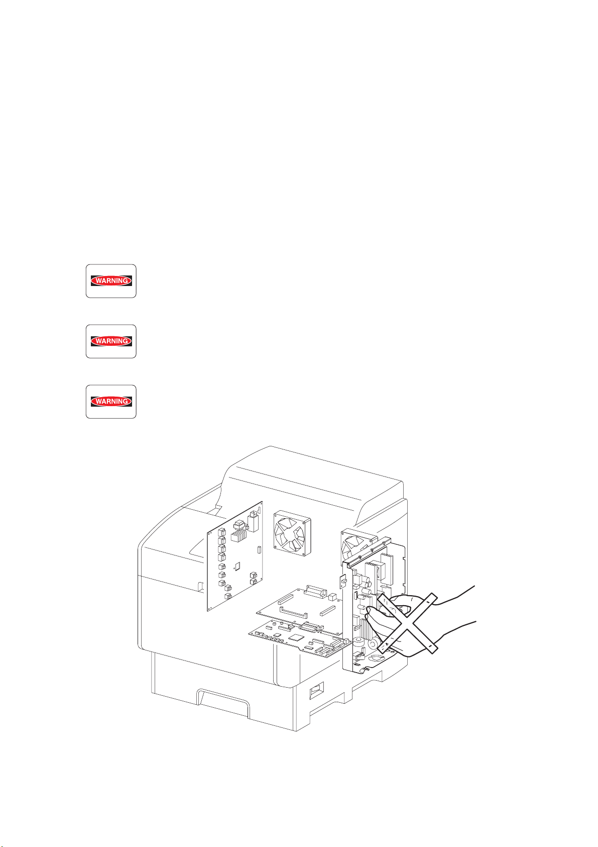
4.1 Power source
Keep the power supply off during maintenance operation to prevent electric shock, burns and other
damages. Keep the power plug disconnected during the maintenance operation.
If the power supply should be kept connected for measurement of voltage or other similar reasons,
sufficient care should be given to prevent electric shock, by following the procedures of this manual.
While the printer is ON, never touch live parts if not required absolutely.
Power is supplied to the power unit (Low Voltage Power Supply ASSY) even while
the printer is off. Never touch its live components.
Do not touch live parts unless otherwise specified.
Intro-3
Ten00002KA
Page 6

4.2 Driving units
When servicing gears or other driving units, be sure to turn them OFF and plug off. Drive them
manually when required.
Never touch the gears or other driving units while the printer is running.
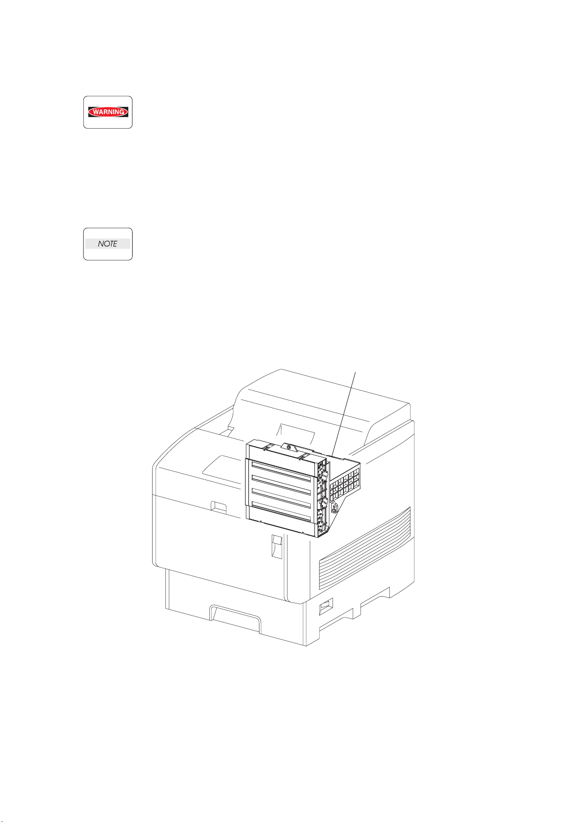
4.3 High-temperature units
When servicing high-temperature units (securing unit, etc.), be sure to turn them OFF to prevent burns,
injuries and other troubles, remove the power plug and start service processes after they have cooled
down enough.
Immediately after completion of operation, they are still hot. Start services after
more than 40 minutes.
Intro-4
Page 7
4.4 Laser beams
• If your eyes are exposed to laser beams, you may lose your eyesight.
• Never open the cover if warning label for laser beams is attached there.
• Before disassembling and reassembling this laser printer, be sure to turn it OFF.
• When servicing this laser printer while it is running, be sure to follow the
procedures specified in this manual.
• You should understand the features of the laser beams which are capable of
having an injurious action on the human body, not to extend the danger over the
workers as well as other people around the printer.
Laser beams have features as follows:
• Frequencies are smaller in width than other beams (sun and electric bulbs) and
phases are uniform so that high monochromatic and convergence performance
can be obtained and thin beams of light can reach places at a long distance.
• Due to the high convergence, beams are concentrated in high density and high
temperature, which is dangerous to human body.
Reference: Laser beams of this laser printer is invisible rays which you cannot see.
PRINT HEAD
Ten00003KA
Intro-5
Page 8
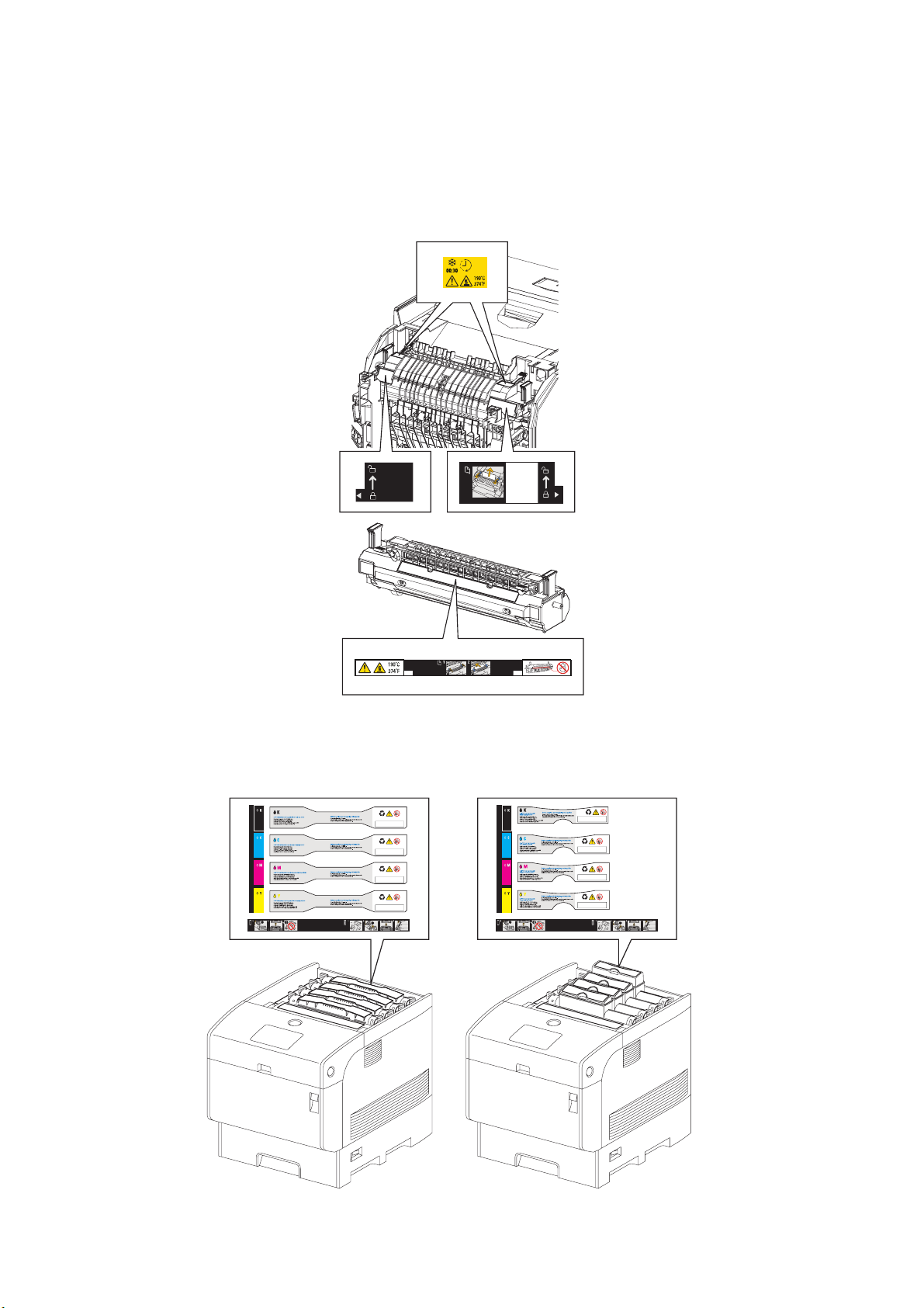
4.5 Warning/caution labels
Warning labels and caution labels are attached to this laser printer to prevent accidents Check those
labels for their peeling or stain when servicing the printer.
4.5.1 Caution label for high-temperature units
4.5.2 Caution label regarding toner cartridge
Ida_Sec00_010FA
Intro-6
Ten00004KA
Page 9
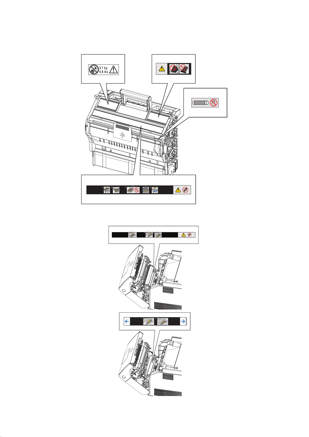
4.5.3 Caution label regarding Imaging Drum and Transfer Roller
Ida_Sec00_005FA
Intro-7
Ida_Sec00_009FA
Page 10
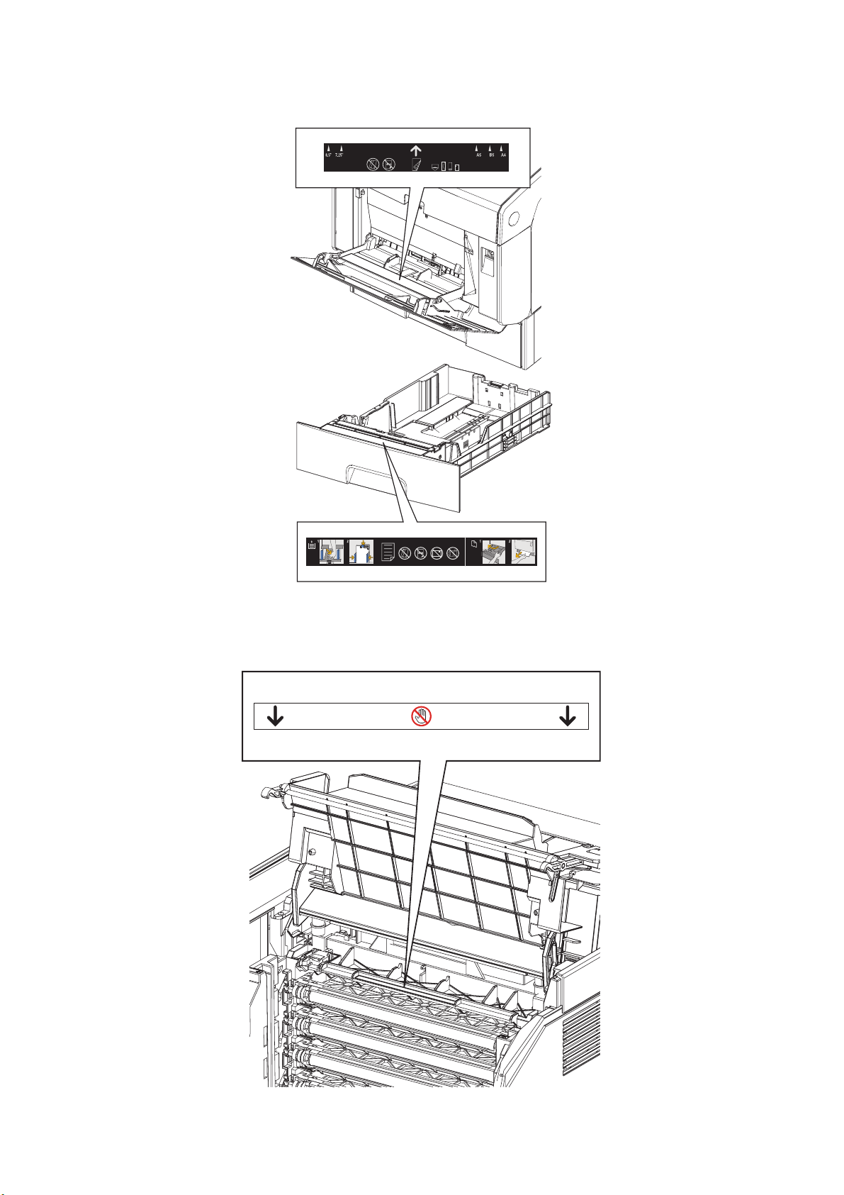
4.5.4 Caution label regarding MPF and paper tray
4.5.5 Caution label regarding Developer Frame
Ida_Sec00_006FA
Intro-8
Ida_Sec00_007FA
Page 11
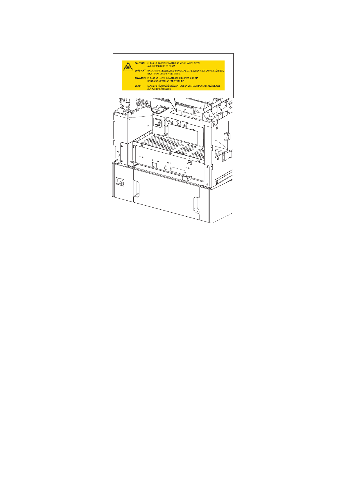
4.5.6 Caution label regarding Print Head
Ida_Sec00_008FA
Intro-9
Page 12
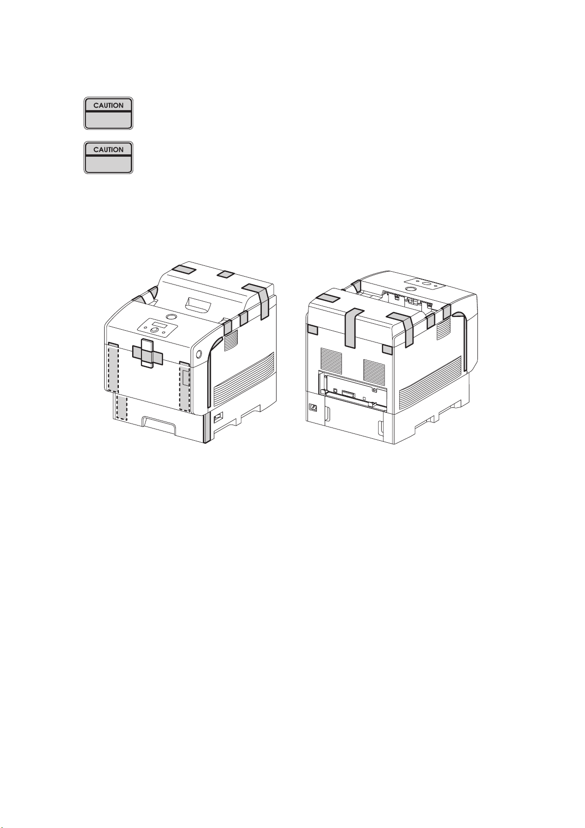
Unpacking the Printer
The printer must be carried horizontally with two or more persons.
Extreme care must be taken to avoid personal injuries.
Ch
eck the printer visually for evidence of any damage.
Peel all tapes off the printer.
Ten00011KA
Intro-10
Page 13

TABLE OF CONTENTS
Cautions for operation ................................................................................................. Intro-1
1. About this manual.....................................................................................................Intro-2
2. Marks giving caution.................................................................................................Intro-2
3. Related documents...................................................................................................Intro-2
4. Safety .......................................................................................................................Intro-3
4.1 Power source..........................................................................................................Intro-3
4.2 Driving unit..............................................................................................................Intro-4
4.3 High-temperature units...........................................................................................Intro-4
4.4 Laser beams...........................................................................................................Intro-5
4.5 Warning/caution labels ...........................................................................................Intro-6
4.5.1 Caution label for high-temperature units .............................................................Intro-6
4.5.2 Caution label regarding toner cartridge ...............................................................Intro-6
4.5.3 Caution label regarding PHD ASSY and BTR ASSY ..........................................Intro-7
4.5.4 Caution label regarding MSI and paper tray........................................................Intro-8
4.5.5 Caution label regarding FRAME ASSY DEVE ....................................................Intro-8
4.5.6 Caution label regarding ROS ASSY....................................................................Intro-9
Unpacking the Printer.................................................................................................Intro-10
Chapter 1 Troubleshooting .............................................................................................1 - 1
Chapter 2 Operation of Diagnostic .................................................................................2 - 1
Chapter 3 Removal and Replacement Procedures ........................................................3 - 1
Chapter 4 Plug/Jack(P/J) Connector Locations..............................................................4 - 1
Chapter 5 Parts List........................................................................................................5 - 1
Chapter 6 Principles of Operation ..................................................................................6 - 1
Chapter 7 Wiring Diagrams and Signal Information .......................................................7 - 1
Chapter 8 Printer Specifications.....................................................................................8 - 1
Intro-11
Page 14

Chapter 1 Troubleshooting
Chapter 1 Troubleshooting CONTENTS
1. Progressing with the Troubleshooting .........................................................................1 - 1
1.1 Flow of Troubleshooting.................................................................................................................... 1 - 1
1.2 Preparatory Requirements................................................................................................................ 1 - 2
1.3 Cautions for Service Operations ....................................................................................................... 1 - 3
1.4 Cautions for FIP Use......................................................................................................................... 1 - 4
2. Level 1 FIP ..................................................................................................................1 - 6
2.1 Level 1 FIP........................................................................................................................................ 1 - 6
2.2 Flow of Level 1 FIP ........................................................................................................................... 1 - 6
3. Level 2 FIP ..................................................................................................................1 - 8
3.1 Level 2 FIP........................................................................................................................................ 1 - 8
3.2 Status Code List................................................................................................................................ 1 - 9
3.3 LCD Display .................................................................................................................................... 1 - 15
3.4 Error Code FIP................................................................................................................................ 1 - 25
FIP-1 001-360/001-363/001-364/001-366 Restart Printer ................................................................... 1 - 25
FIP-2 001-361/001-363/001-365/001-366 Restart Printer ................................................................... 1 - 26
FIP-3 001-362/001-364/001-365/001-366 Restart Printer ................................................................... 1 - 27
FIP-4 003-340/003-341/003-342/003-344/003-345/003-346/003-347/003-348/003-349/
003-350/003-351 Restart Printer ............................................................................................. 1 - 28
FIP-5 003-343 Restart Printer.............................................................................................................. 1 - 29
FIP-6 003-356 Restart Printer.............................................................................................................. 1 - 31
FIP-7 004-310 Restart Printer.............................................................................................................. 1 - 34
FIP-8 006-370/006-371/006-372/006-373/006-374/006-375/006-376/006-377/006-378/
006-379/006-380/006-381/006-382/006-383/006-384 Restart Printer..................................... 1 - 35
FIP-9 007-342/007-345/007-346/007-348 Restart Printer ................................................................... 1 - 36
FIP-10 007-343/007-345/007-347/007-348 Restart Printer ................................................................. 1 - 37
FIP-11 007-344/007-346/007-347/007-348 Restart Printer ................................................................. 1 - 38
FIP-12 009-340/009-341 Restart Printer.............................................................................................. 1 - 39
FIP-13 009-360/009-361/009-362/009-363 Restart Printer ................................................................. 1 - 40
FIP-14 010-354 Restart Printer............................................................................................................ 1 - 41
FIP-15 010-378/010-379/010-380/010-381/010-382/010-383/010-384/010-385/010-386/
010-387/010-388/010-389/010-390/010-391/010-392/010-393/010-394/010-395/
010-396/010-397 Restart Printer ............................................................................................. 1 - 42
FIP-16 016-300/016-301/016-302/016-310/016-311/016-313/016-315/016-317/016-323/
016-324/016-327/016-340/016-344/016-345/016-346 Restart Printer/
Erase Flash Err. 016-392/Write Flash Err. 016-393/Verify Error 016-394 ............................... 1 - 43
FIP-17 016-312 Restart Printer............................................................................................................ 1 - 44
FIP-18 016-316/016-318 Restart Printer.............................................................................................. 1 - 45
FIP-19 016-330/016-331/016-332/016-333/016-334/016-335/016-336/016-337
Restart Printer .......................................................................................................................... 1 - 46
FIP-20 016-338 Restart Printer............................................................................................................ 1 - 48
FIP-21 016-350 Restart Printer............................................................................................................ 1 - 49
FIP-22 016-360/016-361 Restart Printer.............................................................................................. 1 - 50
FIP-23 016-370 Restart Printer............................................................................................................ 1 - 51
FIP-24 Paper Jam 077-902.................................................................................................................. 1 - 52
FIP-25 Paper Jam 077-900.................................................................................................................. 1 - 53
Page 15

Chapter 1 Troubleshooting
Chapter 1 Troubleshooting CONTENTS
FIP-26 Paper Jam 071-101.................................................................................................................. 1 - 54
FIP-27 Paper Jam 077-907.................................................................................................................. 1 - 60
FIP-28 Load Tray N 024-910/024-911/024-912/024-913/024-914 ....................................................... 1 - 61
FIP-29 Exit Tray Full 024-920 .............................................................................................................. 1 - 62
FIP-30 Load MPF 024-969/Load Tray N 024-965/024-966/024-967/024-968/024-969....................... 1 - 63
FIP-31 Tape On XXX Toner 093-919/093-920/093-921/093-922........................................................ 1 - 66
FIP-32 Insert TonerCart 093-970......................................................................................................... 1 - 67
FIP-33 Insert TonerCart 093-971......................................................................................................... 1 - 68
FIP-34 Insert TonerCart 093-972......................................................................................................... 1 - 69
FIP-35 Insert TonerCart 093-973......................................................................................................... 1 - 70
FIP-36 Replace Toner 093-930 ........................................................................................................... 1 - 71
FIP-37 Replace Toner 093-931 ........................................................................................................... 1 - 72
FIP-38 Replace Toner 093-932 ........................................................................................................... 1 - 73
FIP-39 Replace Toner 093-933 ........................................................................................................... 1 - 74
FIP-40 Ready to Print 093-423 ............................................................................................................ 1 - 75
FIP-41 Ready to Print 093-424 ............................................................................................................ 1 - 76
FIP-42 Ready to Print 093-425 ............................................................................................................ 1 - 77
FIP-43 Ready to Print 093-426 ............................................................................................................ 1 - 78
FIP-44 Toner Type 093-980/093-981/093-982/093-983/CRUM ID 093-960/093-961/
093-962/093-963...................................................................................................................... 1 - 79
FIP-45 Insert Drum 091-972 ................................................................................................................ 1 - 81
FIP-46 Imaging Drum 091-935 ............................................................................................................ 1 - 82
FIP-47 Ready to Print 094-402 ............................................................................................................ 1 - 83
FIP-48 Imaging Drum 091-912/CRUM ID 093-965 .............................................................................. 1 - 84
FIP-49 Replace Fuser 010-351............................................................................................................ 1 - 85
FIP-50 Insert Fuser 010-317................................................................................................................ 1 - 86
FIP-51 Ready to Print 010-421 ............................................................................................................ 1 - 87
FIP-52 Fuser Type 010-358/CRUM ID 093-964 .................................................................................. 1 - 88
FIP-53 Transfer Roller 094-911 ........................................................................................................... 1 - 89
FIP-54 Ready to Print 094-422 ............................................................................................................ 1 - 90
FIP-55 BTR Not Detected 094-910...................................................................................................... 1 - 91
FIP-56 Load Tray N 077-912/077-913/077-914/Tray Detached 024-945/024-946/024-947/
024-948/024-949...................................................................................................................... 1 - 92
FIP-57 Close Front Door 077-300........................................................................................................ 1 - 93
FIP-58 CTD Sensor Dirty 092-310/Ready to Print 092-910 ................................................................. 1 - 95
FIP-59 Out of Memory 016-700 ........................................................................................................... 1 - 97
FIP-60 Disk Full 016-980 ..................................................................................................................... 1 - 98
FIP-61 PCL Request 016-720............................................................................................................ 1 - 100
FIP-62 Invalid Job 016-799................................................................................................................ 1 - 101
FIP-63 Ready to Print 193-700 .......................................................................................................... 1 - 102
FIP-64 Invalid ID 016-383/Range Chk Error 016-384/Header Error 016-385/
Check Sum Error 016-386/Format Error 016-387.................................................................. 1 - 103
FIP-65 MPC Error 016-388/MPC Detached 016-389/MPC Com. Failed 016-390 ............................. 1 - 104
FIP-66 Invalid User 016-757/Disabled Func 016-758/Reached Limits 016-759 ................................ 1 - 106
3.5 Image Quality Troubleshooting ..................................................................................................... 1 - 107
3.5.1 Image Quality Specifications................................................................................................. 1 - 109
Page 16

Chapter 1 Troubleshooting
Chapter 1 Troubleshooting CONTENTS
P1 "Light (Undertoned) Prints" ........................................................................................................... 1 - 113
P2 "Blank Prints"................................................................................................................................ 1 - 116
P3 "Solid Prints"................................................................................................................................. 1 - 118
P4 "Vertical deletion or blank line" ..................................................................................................... 1 - 119
P5 "Horizontal deletion or blank line" ................................................................................................. 1 - 122
P6 "Black (color) spots" ..................................................................................................................... 1 - 125
P7 "Background or Foggy Print" ........................................................................................................ 1 - 128
P8 "Skewed paper" ............................................................................................................................ 1 - 130
P9 "Paper Damage"........................................................................................................................... 1 - 134
P10 "Unfused Image or Image Easily Rubs off of Page" ................................................................... 1 - 139
P11 "Vertical Dark Line"..................................................................................................................... 1 - 140
P12 "Afterimage (Ghost)"................................................................................................................... 1 - 141
P13 "Partial Deletion"......................................................................................................................... 1 - 142
P14 "Horizontal Line (Periodical)" ...................................................................................................... 1 - 143
P15 "Fade Horizontal/Vertical"........................................................................................................... 1 - 145
P16 "Color Registration (Color Shift)" ................................................................................................ 1 - 147
3.6 Other FIP ...................................................................................................................................... 1 - 150
FIP-No Power ..................................................................................................................................... 1 - 150
FIP-Multiple Feed................................................................................................................................ 1 - 151
4. Abnormal Noise Trouble..........................................................................................1 - 152
4.1 Entry Chart for Abnormal Noise Troubleshooting ......................................................................... 1 - 152
4.2 Operation Mode Table .................................................................................................................. 1 - 153
FIP-1.N1 When Power is Turned On ................................................................................................. 1 - 153
FIP-1.N2 During Standby................................................................................................................... 1 - 154
FIP-1.N3 During Printing.................................................................................................................... 1 - 155
Page 17

Chapter 1 Troubleshooting CONTENTS
Chapter 1 Troubleshooting
Page 18
Chapter 1 Troubleshooting
Troubleshooting in this manual assumes use of Diag. tools (maintenance tools).
However, the troubleshooting allows for the case where the Diag tools are not
used. You can correct troubles according to these troubleshooting procedures
after understanding them well.
1. Progressing with the Troubleshooting
After making sure of actual condition of a trouble, proceed with the troubleshooting process efficiently
making use of the Fault Isolation Procedure (FIP), Operation of Diag. tools (Chapter 2), Wire
connecting diagram (Chapter 7), and Principle of operation (Chapter 6).
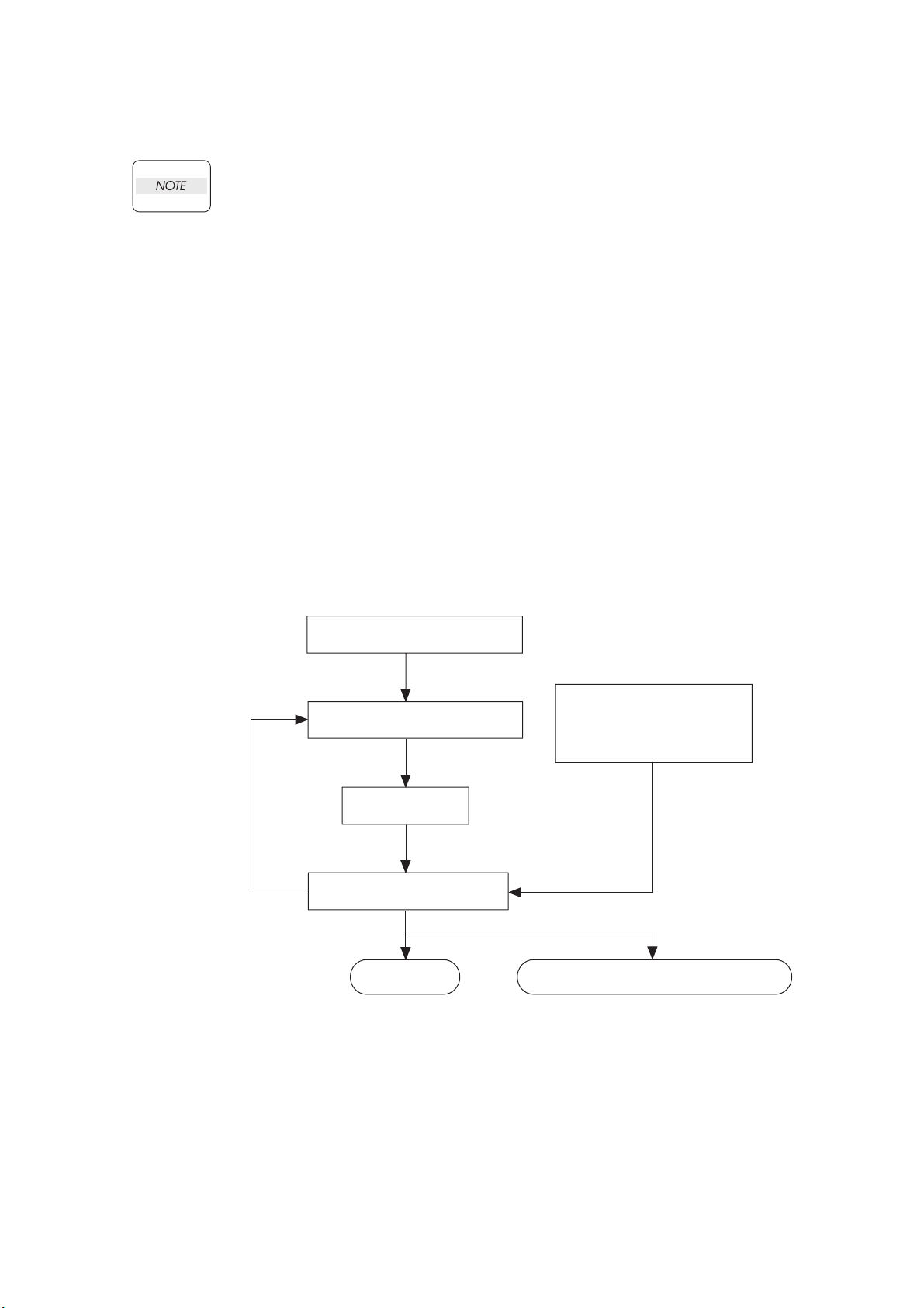
1.1 Flow of Troubleshooting
Flow of the troubleshooting is as follows:
Installation status check
Trouble status check
Execute FIP
Trouble recovery check
End
Operation of Diagnostic
Principles of Operation
Wiring Diagrams
Reference
information
When a problem can not be settle
Send back printer or parts to
the factory, check it the engineer.
1 – 1
Page 19

Chapter 1 Troubleshooting
1.2 Preparatory Requirements
Be sure to check the following items before starting the troubleshooting procedures:
1) Voltage of the power supply is within the specifications (measure the voltage at the electric outlet).
2) Power cord is free from breakage, short-circuit, disconnected wire, or incorrect connection in the
power cord.
3) The laser printer is properly grounded.
4) The laser printer is not installed at a place subjected to too high temperature, too high humidity, too
low temperature, too low humidity or rapid change of temperature.
5) The laser printer is not installed close to water service, humidifier, heat generating unit, or fire, in
very dusty place, or a place exposed to air flow from the air conditioning system.
6) The laser printer is not installed in a place where volatile gas or inflammable gas is generated.
7) The laser printer is not installed under direct sunbeams.
8) The laser printer is installed in a well-ventilated place.
9) The laser printer is installed on a stout and stable plane.
10) Paper used meets specifications (standard paper is recommendable).
11) The laser printer is handled properly.
12) Parts which should be periodically replaced are replaced each time when specified number of
sheets have been printed.
13) Make the PHD ASSY and the FRAME ASSY DEVE reseated, and try some printing using the
papers out of a newly opened package.
1 – 2
Page 20

Chapter 1 Troubleshooting
1.3 Cautions for Service Operations
1) Be sure to remove the power cord except when it is specifically required.
If the printer is kept ON, never touch the conductive parts while it is not specifically
required.
The power switch/inlet of LVPS is live even while the power supply is cut off. Never
touch the live parts.
2) When checking some parts with covers removed and with the interlock and safety and power
switches ON, remove the connector (P/J151) on the ROS ASSY except when it is specifically
required.
When checking some parts with covers removed and with the interlock and safety
and power switches ON, laser beams may be irradiated from the ROS ASSY. Since
it is dangerous, be sure to remove the connector (P/J151) while it is not required.
3) When checking some parts with the left cover removed and power ON, be sure to remove the
connector (P/J141) on the HVPS while it is not required.
When checking some parts with the left cover removed and power ON, high voltage
may be applied by the HVPS. Be sure to remove the connector (P/J141) on the
HVPS.
When connecting the connector (P/J141) on the HVPS according to the instructions
of the FIP, never touch the HVPS and parts of high voltage.
4) When using Diag. tools or other tools of high voltage, be sure to keep them covered except when
otherwise specified.
When using Diag.Tool or other tools of high voltage, never touch parts of high
voltage.
When using Diag.Tool or other tools of high voltage, be sure to follow the
procedure of this manual.
5) When operating the driving units using the Diag or other tools, be sure to keep them covered
unless otherwise specified.
When operating the driving units using the Diag or other tools, never touch the
driving units. When operating the driving units using Diag or other tools, be sure
to observe the procedures in this manual.
6) When touching hot parts, be careful not to get burnt.
7) Workers should wear a wrist band or the like to remove static electricity from their body , grounding
their body while working.
1 – 3
Page 21

Chapter 1 Troubleshooting
1.4 Cautions for FIP Use
1) It is assumed in the FIP that the printer controller (CONTROLLER PWB) is normally functioning. If
any trouble cannot be corrected by troubleshooting, replace the printer controller with a normal one
and check for proper operation again.
If the trouble is not still corrected, replace the major parts and then related parts in succession and
confirm according to the procedure of the "Initial check" and "Major check parts".
2) When troubleshooting according to the FIP, normal MCU PWB, PHD ASSY or other parts may be
necessary for isolation of failed parts. Prepare them in advance.
3) In the initial check according to the FIP, check only items which can be simply checked.
4) In the initial check according to the FIP, check the constitutive parts of the major check parts and
related parts, as well as major check parts.
5) When working with the printer, Be sure to remove the power cord except when required specifi-
cally. Never touch live parts if not required, while the power cord is connected.
6) Connector condition is denoted as follows:
[P/J12] → Connector (P/J12) is connected.
[P12] → Plug side with the connector (P/J12) removed (except when attached directly to the
board).
[J12] → Jack side with the connector (P/J12) removed (except when attached directly to the
board).
7) [P/J1-2PIN <=> P/J3-4PIN] in the FIP means measurement with the plus side of the measuring
instrument connected to [P/J1] and the minus side to [4PIN] of [P/J3].
8) [P/J<=>P/12] in the FIP means measurement for all terminals corresponding between [P/J1] and
[P/J2] referring to "Wire connecting diagram".
9) In [P/J1-2PIN <=> P/J3-4PIN] in the FIP where voltage is measured, [P/J3-4PIN] on the rear minus
side is always at the AG (analog ground), SG (signal ground), or RTN (return).
Therefore, after checking of proper conduction between AGs, SGs, or RTNs respectively, the rear
minus side can be connected to the PIN of AG, SG or RTN instead of [P/J3-4PIN].
However, care should be taken not to mistake since [AG], [SG], and [RTN] are not on the same
level.
10) Measure the voltage of small connectors with the special tool. Handle the tool with care, as the
leading edge of the tool is pointed.
11) When measuring the voltage, set the PDH ASSY, FUSER ASSY, BRT ASSY and paper tray, close
the FRONT COVER ASSY and power ON if not required specifically.
12) Numerical values in the FIP are only for standard. If numerical values are approximate, they
should be considered permissible.
1 – 4
Page 22

Chapter 1 Troubleshooting
13) Parts which are always removed to check as indicated in the FIP and procedures for that purpose
are not specifically referred to here. They should be handled carefully.
14) "Replacement" in the FIP indicates replacement of parts which are considered to be the source of
trouble to be checked after replacing those parts, assemblies containing them, or parts (HIGH
ASSY).
15) In the FIP, the paper pick-up unit by means of the paper tray at the lower part of the printer is
referred to as "try 1", the first level of the paper pick-up unit feeder unit as "try 2", and the second
level as the "tray3".
16) In the FIP, existence and non-existence of Diag tools (maintenance tools,) are distinguished in
some cases. Correct troubles according to the instructions in the FIP.
17) In the FIP, procedures are differentiated depending on specifications. Correct troubles according
to the instructions in the FIP.
18) For optional parts, some troubleshooting procedure may follow the manual for those options, of
which you should take note.
Keep those manuals for the optional parts when required.
1 – 5
Page 23

Chapter 1 Troubleshooting
2. Level 1 FIP
2.1 Level 1 FIP
The level 1 FIP is the first step for trouble diagnosis. The level 1 FIP isolates the presence of various
troubles including error codes, and the level 2 FIP provides a guide for proceeding of the
troubleshooting.
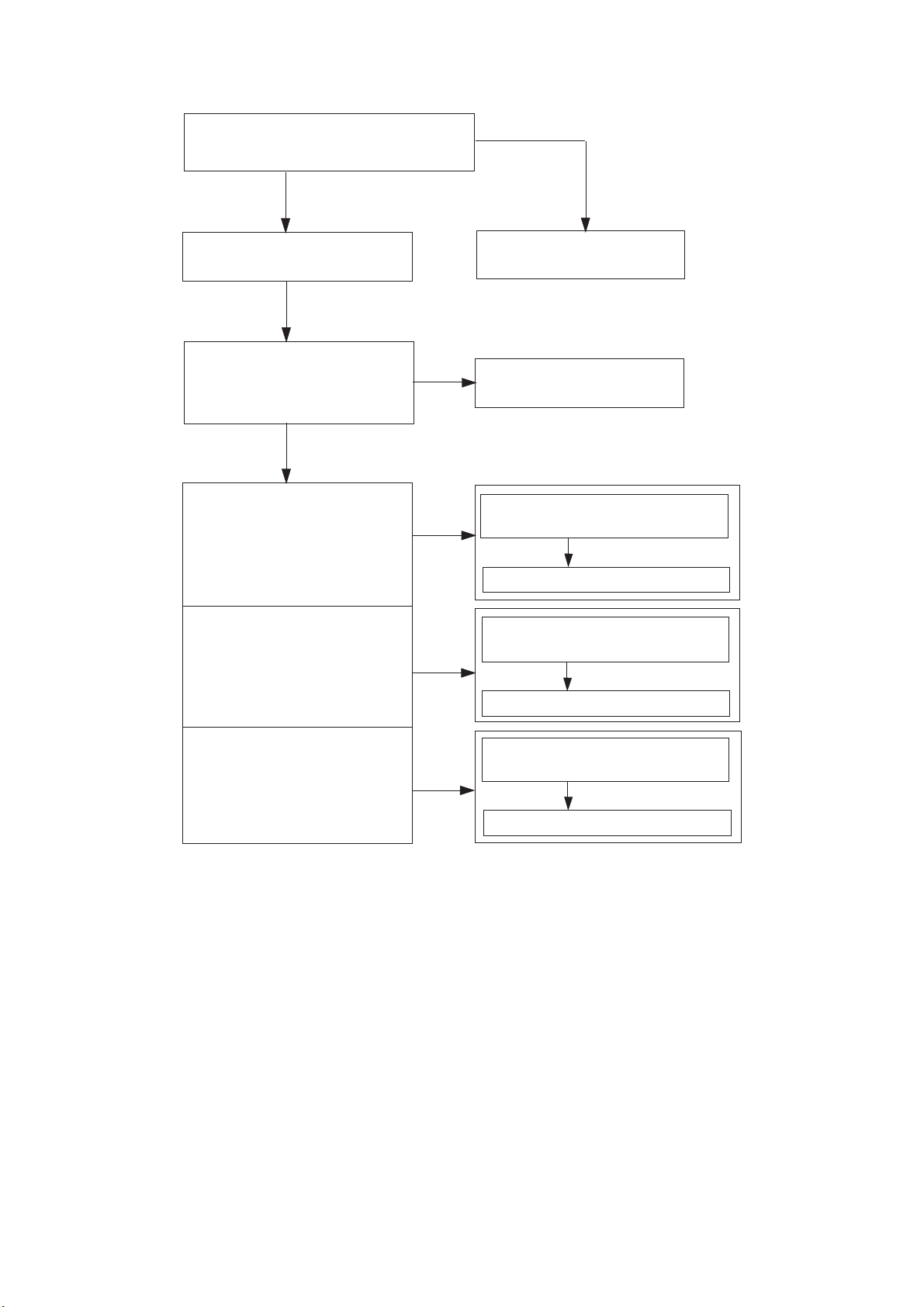
2.2 Flow of Level 1 FIP
Before commencing Troubleshooting, verify or fix the following general matters first.
Verify the type and size of the
print media installed meet the
specifications.
Yes
Verify that the settings of the
printer for the type and size of
the print media are correct.
Yes
Reinstall the Fuser Assy, BTR
Assy, PHD Assy and four
TONER Cartridges to the printer.
Yes
Inspect there is no damage on
the tabs for safety interlock of
the Covers and Doors.
Yes When a paper
is jammed
Go to FIP.
Remove the paper jams from
the printer.
Yes
If not
If not
If not
Reinstall the print media fall
within the print media guidelines.
Reset the printer settings.
Replace the damaged parts.
Verify the scraps of paper,
staples, paper-clips and so on
are not remained in the printer.
Yes
Go to FIP.
If not
Remove the remaining obstacles.
1 – 6
Page 24
Chapter 1 Troubleshooting
Ask the operator about trouble status.
Is operator’s operating method correct?
Y
Turn off and turn on the Power.
Does error still occur when print
is done by the problem mode?
Y
When status code or LCD
display is displayed:
N
Instruct how to operate
N
End of work
Refer to "3.2 Status Code List."
Refer to "3.3 LCD Display."
When image quality trouble
is occurred:
When abnormal noise
is occurred:
Refer to "3.4 Error Code FIP."
Refer to "3.5 Entry Chart for Image
Quality Troubleshooting."
Refer to "3.5 Image Quality FIP."
Refer to "4.1 Entry Chart for
Abnormal Noise Troubleshooting."
Refer to "4.2 Operation Mode Table."
1 – 7
Page 25

Chapter 1 Troubleshooting
3. Level 2 FIP
3.1 Level 2 FIP
The Level 2 FIP is the trouble diagnostic procedure to sort various troubles in addition to the error
codes. In the troubleshooting, executing the steps given in the FIP or checking procedure allows you to
find out a cause of trouble in a short time.
1 – 8
Page 26
3.2 Status Code List
Chapter 1 Troubleshooting
Error Message Error Contents
001-360
Restart Printer
Flip
Contact Support
IfMessageReturns
001-361
Restart Printer
Flip
Contact Support
IfMessageReturns
001-362
Restart Printer
Flip
Contact Support
IfMessageReturns
001-363
Restart Printer
Flip
Contact Support
IfMessageReturns
001-364
Restart Printer
Flip
Contact Support
IfMessageReturns
001-365
Restart Printer
Flip
Contact Support
IfMessageReturns
001-366
Restart Printer
Flip
Contact Support
IfMessageReturns
003-340 to 003-342
Restart Printer
Flip
Contact Support
IfMessageReturns
003-343
Restart Printer
Flip
Contact Support
IfMessageReturns
<IOT Fan Motor 1 Failure>
MCU detects an error upon receiving error signal from the Rear Fan.
<IOT Fan Motor 2 Failure>
MCU detects an error upon receiving error signal from the Front Fan.
<IOT Fan Motor 3 Failure>
MCU detects an error upon receiving error signal from the LV Fan.
<IOT Fan Motor 4 Failure>
MCU detects an error upon receiving error signals from the Rear and
Front Fans.
<IOT Fan Motor 5 Failure>
MCU detects an error upon receiving error signals from the Rear and
LV Fans.
<IOT Fan Motor 6 Failure>
MCU detects an error upon receiving error signals from the Front and
LV Fans.
<IOT Fan Motor 6 Failure>
MCU detects an error upon receiving error signals from the Front,
Rear and LV Fans.
<IOT Firmware Error>
Firmware Error is detected.
<IOT Firmware Error>
CRUM communication error is detected.
FIP to be
referred
FIP-1
FIP-2
FIP-3
FIP-1
FIP-2
FIP-1
FIP-3
FIP-2
FIP-3
FIP-1
FIP-2
FIP-3
FIP-4
FIP-5
1 – 9
Page 27
Chapter 1 Troubleshooting
Error Message Error Contents
003-344 to 003-351
Restart Printer
Flip
Contact Support
IfMessageReturns
003-356
Restart Printer
Flip
Contact Support
IfMessageReturns
004-310
Restart Printer
Flip
Reseat Feeder
Contact Support
006-370 to 006-384
Restart Printer
Flip
Contact Support
IfMessageReturns
007-342
Restart Printer
Flip
Contact Support
IfMessageReturns
007-343
Restart Printer
Flip
Contact Support
IfMessageReturns
007-344
Restart Printer
Flip
Contact Support
IfMessageReturns
007-345
Restart Printer
Flip
Contact Support
IfMessageReturns
007-346
Restart Printer
Flip
Contact Support
IfMessageReturns
007-347
Restart Printer
Flip
Contact Support
IfMessageReturns
<IOT Firmware Error>
Firmware Error is detected.
<IOT NVRAM Error>
NVRAM and CRUM errors are detected.
<IOT Option Feeder Communication Error>
Option Feeder Communication Error is detected.
Communication error between the Option Feeder and the printer.
<IOT ROS Motor Failure>
The SOS signal does not come from the ROS ASSY.
<IOT Motor Failure>
Main Motor fail is detected.
MCU detects an error upon receiving error signal from the Motor.
<IOT Motor Failure>
Deve Motor fail is detected.
MCU detects an error upon receiving error signal from the Motor.
<IOT Motor Failure>
Fuser Motor fail is detected.
MCU detects an error upon receiving error signal from the Motor.
<IOT Motor Failure>
Main and Deve Motor fails are detected.
MCU detects an error upon receiving error signal from the Motors.
<IOT Motor Failure>
Main and Fuser Motor fails are detected.
MCU detects an error upon receiving error signal from the Motors.
<IOT Motor Failure>
Deve and Fuser Motor fails are detected.
MCU detects an error upon receiving error signal from the Motors.
FIP to be
referred
FIP-4
FIP-6
FIP-7
FIP-8
FIP-9
FIP-10
FIP-11
FIP-9
FIP-10
FIP-9
FIP-11
FIP-10
FIP-11
1 – 10
Page 28
Chapter 1 Troubleshooting
Error Message Error Contents
007-348
Restart Printer
Flip
Contact Support
IfMessageReturns
009-340/009-341
Restart Printer
Flip
Clean CTD
Contact Support
009-360
Restart Printer
Flip
Reseat Y Toner
Contact Support
009-361
Restart Printer
Flip
Reseat M Toner
Contact Support
009-362
Restart Printer
Flip
Reseat C Toner
Contact Support
009-363
Restart Printer
Flip
Reseat K Toner
Contact Support
010-354
Restart Printer
Flip
Contact Support
IfMessageReturns
010-378 to 010-397
Restart Printer
Flip
Reseat Fuser
Contact Support
016-300
Restart Printer
Flip
Contact Support
IfMessageReturns
016-301
Restart Printer
Flip
Contact Support
IfMessageReturns
<IOT Motor Failure>
Main, Deve and Fuser Motor fails are detected.
MCU detects an error upon receiving error signal from the Motors.
<IOT CTD Sensor Error>
CTD (ADC) Sensor Error is detected.
CTD (ADC) Sensor error at calibrating.
<IOT (Y) Toner CRUM Error>
Yellow Toner CRUM Communication Error is detected.
Printer can not read the CRUM data of the yellow toner cartridge.
<IOT (M) Toner CRUM Error>
Magenta Toner CRUM Communication Error is detected.
Printer can not read the CRUM data of the magenta toner cartridge.
<IOT (C) Toner CRUM Error>
Cyan Toner CRUM Communication Error is detected.
Printer can not read the CRUM data of the cyan toner cartridge.
<IOT (K) Toner CRUM Error>
Black Toner CRUM Communication Error is detected.
Printer can not read the CRUM data of the black toner cartridge.
<IOT Environment Sensor Error>
Temperature Sensor Error is detected.
Temperature Sensor detected abnormal temperature.
<IOT Fuser Fail>
Fuser Error is detected.
<ESS Data Cache Error>
CPU data cache error
<ESS Instruction Cache Error>
CPU instruction cache error
FIP to be
referred
FIP-9
FIP-10
FIP-11
FIP-12
FIP-13
FIP-13
FIP-13
FIP-13
FIP-14
FIP-15
FIP-16
FIP-16
1 – 11
Page 29
Chapter 1 Troubleshooting
Error Message Error Contents
016-302
Restart Printer
Flip
Contact Support
IfMessageReturns
016-310
Restart Printer
Flip
Contact Support
IfMessageReturns
016-311
Restart Printer
Flip
Contact Support
IfMessageReturns
016-312
Restart Printer
Flip
Contact Support
IfMessageReturns
016-313
Restart Printer
Flip
Contact Support
IfMessageReturns
016-315
Restart Printer
Flip
Contact Support
IfMessageReturns
016-316
Restart Printer
Flip
Reseat Memory
Contact Support
016-317
Restart Printer
Flip
Contact Support
IfMessageReturns
016-318
Restart Printer
Flip
Contact Support
IfMessageReturns
016-323
Restart Printer
Flip
Contact Support
IfMessageReturns
<ESS Illegal Exception>
CPU illegal exception
<ESS FontROM SumCheckError (Main)>
Checksum error in the built-in font ROM
<ESS FontROM SumCheckErrorOption>
Checksum error in the option font ROM
<ESS HDD Error>
The error is detected by HDD error.
<ASIC Error>
The error is detected by ASIC error.
<ESS On Board RAM W/R Check Error>
The error is detected by On board RAM W/R check during
initialization.
<ESS DIMM Slot RAM W/R Check Error>
The error is detected by DIMM slot RAM W/R check during
initialization.
<ESS ROM Check (Main) Error>
Checksum error in the main program ROM
<ESS DIMM Slot RAM Error>
DIMM slot RAM (option) error occurs during the initialization.
<ESS NVRAM1 W/R Check Error>
The error is detected by master NVRAM W/R check.
FIP to be
referred
FIP-16
FIP-16
FIP-16
FIP-17
FIP-16
FIP-16
FIP-18
FIP-16
FIP-18
FIP-16
1 – 12
Page 30
Chapter 1 Troubleshooting
Error Message Error Contents
016-324
Restart Printer
Flip
Contact Support
IfMessageReturns
016-327
Restart Printer
Flip
Contact Support
IfMessageReturns
016-330
Restart Printer
Flip
Contact Support
IfMessageReturns
016-331
Restart Printer
Flip
Reseat MPC
Contact Support
016-332
Restart Printer
Flip
Reseat MPC
Contact Support
016-333
Restart Printer
Flip
Reseat MPC
Contact Support
016-334
Restart Printer
Flip
Reseat MPC
Contact Support
016-335
Restart Printer
Flip
Reseat MPC
Contact Support
016-336
Restart Printer
Flip
Reseat MPC
Contact Support
016-337
Restart printer
Flip
Reseat MPC
Contact Support
<ESS NVRAM2 W/R Check Error>
The error is detected by master NVRAM2 W/R check.
<ESS NVRAM1 SIZE And ID Check Error>
The error is detected by consistency check between the NVRAM size
required by the system and its actual size, and by consistency check
of the ID recorded when turning ON the power first.
<MPC-ESS Communication Fail>
Communication fail between MPC and ESS
<MPC Flash ROM Boot Module Checksum Error>
Checksum error in the Flash ROM
<MPC RAM R/W Test Error>
The error is detected by MPC RAM W/R check.
<MPC Flash ROM Application Module Checksum Error>
Checksum error in the MPC Flash ROM
<MPC MAC Address Checksum Error>
Checksum error in the MPC MAC address
<MPC Ethernet BIST Parity/RAM R/W Error>
The error is detected by MPC Ethernet BIST parity RAM R/W check.
<MPC Internal Loopback Error>
The error is detected by Loopback test.
<MPC Fatal Error>
The fatal error is detected by MPC check.
FIP to be
referred
FIP-16
FIP-16
FIP-19
FIP-19
FIP-19
FIP-19
FIP-19
FIP-19
FIP-19
FIP-19
1 – 13
Page 31

Chapter 1 Troubleshooting
Error Message Error Contents
016-338
Restart Printer
Flip
Reseat Wireless
Contact Support
016-340
Restart Printer
Flip
Contact Support
IfMessageReturns
016-344
Restart Printer
Flip
Contact Support
IfMessageReturns
016-345
Restart Printer
Flip
Contact Support
IfMessageReturns
016-346
Restart Printer
Flip
Contact Support
IfMessageReturns
016-350
Restart Printer
Flip
Reseat Parallel
Contact Support
016-360
Restart Printer
Flip
Reseat MPC
Contact Support
016-361
Restart Printer
Flip
Reseat HDD
Contact Support
016-370
Restart Printer
Flip
Reseat Parallel
Contact Support
<Wireless Option Error>
The error is detected by Wireless Option check.
<ESS Network Communication Error>
Communication error between CPU network and ESS firmware
<ESS Network MAC Address Checksum Error>
Checksum error in the Network MAC address
<ESS Network Ethernet BIST parity/RAM R/W Error>
The fail is detected by Network Ethernet parity RAM R/W check.
<ESS Network Internal Loopback Error>
The error is detected by On Board Network Internal Loopback check.
<IEEE1284 Data Error>
The error is detected by IEEE1284 controller.
<PCI Option#0 (MPC I/F Connector) Fail>
Detection error of PCI option 0
<PCI Option#1 (HDD I/F Connector) Fail>
Detection error of PCI option 1
<MCU-ESS Communication Fail>
Communication fail between MCU and ESS
FIP to be
referred
FIP-20
FIP-16
FIP-16
FIP-16
FIP-16
FIP-21
FIP-22
FIP-22
FIP-23
1 – 14
Page 32

3.3 LCD Display
Chapter 1 Troubleshooting
Problem Error Message Error Contents
Paper Jam
Paper Jam
077-902
Flip
Open Front Latch
Remove Paper
Paper Jam
077-900
Flip
Open Front Latch
Remove Paper
Paper Jam
071-101
Flip
Open Tray
Remove Paper
Flip
Open & close
Front Latch
Paper Jam
077-907
Flip
Push Side Button
Remove Paper
<IOT Fuser Jam>
1. The exit sensor cannot detect passage of paper
within specified time.
2. The exit sensor detected a paper while power is
on or interlock is closed.
<IOT Registration Jam>
1. The regi sensor cannot detect passage of paper
within specified time.
2. The regi sensor detected a paper while power is
on or interlock is closed.
<IOT Feed Jam>
The regi sensor cannot detect paper within specified
time.
<IOT Duplex Jam>
1. The duplex jam sensor cannot detect passage of
paper within specified time.
2. The duplex jam sensor detected a paper while
power is on or interlock is closed.
FIP to be
referred
FIP-24
FIP-25
FIP-26
FIP-27
1 – 15
Page 33

Chapter 1 Troubleshooting
Problem Error Message Error Contents
Load Tray N
024-910, 024-911, 024912, 024-913, 024-914
Flip
Load Tray N
XXX
Flip
Load Tray N
YYY
NOTE:
N: Tray number
XXX: Paper size
YYY: Media type
024-910: Tray 1
024-911: Tray 2
024-912: Tray 3
024-913: Tray 4
024-914: MPF
Exit Tray Full
024-920
Flip
Empty Exit Tray
Load MPF
024-969
<IOT Paper Size Mismatch>
The paper size mismatch is detected.
<IOT Standard Stacker Full>
The Exit tray full is detected.
Printed paper on the Exit Tray exceeds the 250
sheets.
Flip
Paper Setting
Load MPF
XXX
Flip
Load MPF
YYY
NOTE:
XXX: Paper size
YYY: Media type
Load Tray N
024-965, 024-966, 024967, 024-968, 024-969
Flip
Load Tray N
XXX
Flip
Load Tray N
YYY
NOTE:
N: Tray number
XXX: Paper size
YYY: Media type
024-965: Tray 1
024-966: Tray 2
024-967: Tray 3
024-968: Tray 4
024-969: MPF
<Specified Tray Empty>
When a tray is specified, the tray is empty.
<No Suitable Paper>
1. When the printer is waiting for a job or APS is
specified, all the trays (including MPF) installed
on the printer are empty. (All Tray Empty)
2. When APS is specified, a size of paper in all trays
(including MPF) is mismatched. (All Tray Size
Mismatch)
3. When a tray is specified, a size of paper in the
specified tray (including MPF) is mismatched.
(Specified Tray Size Mismatch)
FIP to be
referred
FIP-28
FIP-29
FIP-30
1 – 16
Page 34

Chapter 1 Troubleshooting
Problem Error Message Error Contents
Tape On XXX Toner
093-919, 093-920, 093921, 093-922
Flip
<IOT Toner Tape Staying>
The toner tape staying is detected.
When a new toner cartridge installed, the MCU does
not detect the toner cartridge.
<IOT Toner Detached>
The yellow, magenta, cyan or black toner cartridge
detached is detected.
Toner Cartridge Sensor on the BOX ASSY CRUM
READER can not detect the toner cartridge.
<IOT Toner Empty>
The toner empty is detected.
The value of the Toner Cartridge counter has
reached the replacement time.
The No Toner Sensor on the DISPENSER ASSY HI
detected the no toner.
To ne r
Remove Tape
From XXX Toner
NOTE:
XXX: Toner color
093-919: Yellow
093-920: Magenta
093-921: Cyan
093-922: Black
Insert TonerCart
093-970, 093-971, 093972, 093-973
Flip
Insert
XXX Toner
NOTE:
XXX: Toner color
093-970: Yellow
093-971: Magenta
093-972: Cyan
093-973: Black
Replace Toner
093-930, 093-931, 093932, 093-933
Flip
Replace
XXX Toner
NOTE:
XXX: Toner color
093-930: Yellow
093-931: Magenta
093-932: Cyan
093-933: Black
Ready to Print
093-423, 093-424, 093425, 093-426
Flip
XXX Toner
Is Low
NOTE:
XXX: Toner color
093-423: Yellow
093-424: Magenta
093-425: Cyan
093-426: Black
<IOT Toner Near Empty>
Toner near empty is detected.
The value of the Toner Cartridge counter is going to
reach the replacement time.
FIP to be
referred
FIP-31
FIP-32 (Y)
FIP-33 (M)
FIP-34 (C)
FIP-35 (K)
FIP-36 (Y)
FIP-37 (M)
FIP-38 (C)
FIP-39 (K)
FIP-40 (Y)
FIP-41 (M)
FIP-42 (C)
FIP-43 (K)
1 – 17
Page 35

Chapter 1 Troubleshooting
Problem Error Message Error Contents
Toner Type
093-980, 093-981, 093982, 093-983
Flip
<IOT Toner Type Error>
The toner type error is detected.
The CRUM data the CRUM Sensor read was the
type of the other company.
To ne r
Reseat
XXX Toner
NOTE:
XXX: Toner color
093-980: Yellow
093-981: Magenta
093-982: Cyan
093-983: Black
CRUM ID
093-960, 093-961, 093962, 093-963
Flip
<IOT CRUM ID Error (Toner)>
The toner CRUM ID error is detected.
The toner cartridge CRUM ID read by the sensor is
different from the one that was recorded.
<IOT PHD Detached>
The PHD detached is detected.
<IOT PHD Life Over>
The PHD life over is detected.
<PHD Life Warning>
The PHD life warning is detected.
The value of the PHD counter has reached the
replacement time.
<IOT PHD Type Error>
The PHD type error is detected.
The CRUM data the MCU read was the type of the
other company.
<IOT CRUM ID Error>
The imaging drum CRUM ID error is detected.
The toner cartridge CRUM ID read by the MCU is
different from the one that was recorded.
PHD ASSY
Reseat
XXX Toner
NOTE:
XXX: Toner color
093-960: Yellow
093-961: Magenta
093-962: Cyan
093-963: Black
Insert Drum
091-972
Flip
Insert/Reseat
Imaging Drum
Imaging Drum
091-935
Flip
Replace
Imaging Drum
Ready to Print
094-402
Flip
Imaging Drum
Replace Soon
Imaging Drum
091-912
Flip
Reseat
Imaging Drum
CRUM ID
093-965
Flip
Reseat
Imaging Drum
FIP to be
referred
FIP-44
FIP-44
FIP-45
FIP-46
FIP-47
FIP-48
FIP-48
1 – 18
Page 36

Chapter 1 Troubleshooting
Problem Error Message Error Contents
Fuser
BTR
Replace Fuser
010-351
Flip
Replace
Fuser
Insert Fuser
010-317
Flip
Reseat Fuser
Ready to Print
010-421
Flip
Replace Fuser
Soon
Fuser Type
010-358
Flip
Reseat
Fuser
CRUM ID
093-964
Flip
Reseat
Fuser
Transfer Roller
094-911
Flip
Replace
Transfer Roller
Ready to Print
094-422
Flip
Replace Transfer
Roller Soon
BTR Not Detected
094-910
Flip
Insert/Reseat
Transfer Roller
<IOT Fuser Life Over 2>
The fuser life over is detected.
The value of the Fuser counter has reached the
replacement time.
<IOT Fuser Detached>
The fuser detached is detected.
<Fuser Life Warning>
The fuser life warning is detected.
The value of the Fuser counter is going to reach the
replacement time.
<IOT Fuser Type Error>
The fuser type error is detected.
The CRUM data the MCU read was the type of the
other company.
<IOT CRUM ID Error>
The fuser CRUM ID error is detected.
The Fuser CRUM ID read by the MCU is different
from the one that was recorded.
<IOT BTR Life Over>
The BTR life over is detected.
The value of the BTR counter has reached the
replacement time.
<BTR Life Warning>
The BTR life warning is detected.
The value of the BTR counter is going to reach the
replacement time.
<IOT BTR Detached>
The BTR detached is detected.
The CTD (ADC) Sensor detected the BTR
detached.
FIP to be
referred
FIP-49
FIP-50
FIP-51
FIP-52
FIP-52
FIP-53
FIP-54
FIP-55
1 – 19
Page 37

Chapter 1 Troubleshooting
Problem Error Message Error Contents
Load Tray N
077-912, 077-913, 077-
Tray
914
Flip
Push In
Tray N
NOTE:
N: Tray number
077-912: Tray 1
077-913: Tray 2
077-914: Tray 3
Tray Detached
024-945
Flip
Push in
Tray
Tray Detached
024-946, 024-947, 024948, 024-949
Flip
Push in
Tray N
NOTE:
N: Tray number
024-946: Tray 1
024-947: Tray 2
024-948: Tray 3
024-949: Tray 4
<Upper Cassette Detached>
1. When APS is specified, any trays located above
the feedeable tray are open.
2. When a tray is specified, any trays located above
the specified tray are open.
The Tray Size Switch detected the no tray.
<Tray Detached>
When the printer is waiting for a job or APS is
specified, all the trays are detached. (All Tray
Detached)
The Tray Size Switch detected the no tray.
<Tray Detached>
When a tray is specified, the tray is detached.
(Specified Tray Detached)
The Tray Size Switch detected the no tray.
FIP to be
referred
FIP-56
1 – 20
Page 38

Chapter 1 Troubleshooting
Problem Error Message Error Contents
Load Tray N
024-965, 024-966, 024967, 024-968
Flip
Load Tray N
XXX
Flip
Load Tray N
Tray
YYY
NOTE:
N: Tray number
XXX: Paper size
YYY: Media type
024-965: Tray 1
024-966: Tray 2
024-967: Tray 3
024-968: Tray 4
Load MPF
024-969
Flip
Load MPF
XXX
<No Suitable Paper>
1. When the printer is waiting for a job or APS is
specified, all the trays (including MPF) installed
on the printer are empty. (All Tray Empty)
2. When APS is specified, a size of paper in all trays
(including MPF) is mismatched. (All Tray Size
Mismatch)
3. When a tray specified, the tray is empty.
(Specified Tray Empty)
4. When a tray is specified, a size of paper in the
specified tray (including MPF) is mismatched.
(Specified Tray Size Mismatch)
Flip
Load MPF
YYY
NOTE:
XXX: Paper size
YYY: Media type
Close Front Door
Cover Open
077-300
Flip
Front Door
Is Open
<IOT Cover Front Open>
The front cover is open.
FIP to be
referred
FIP-30
FIP-57
1 – 21
Page 39

Chapter 1 Troubleshooting
Problem Error Message Error Contents
Other
CTD Sensor Dirty
092-310
Flip
Clean
CTD Sensor
Ready to Print
092-910
Flip
Clean
CTD Sensor
Out of Memory
016-700
Flip
Job too Large
Press Set
Disk Full
016-980
Flip
Job too Large
Press Set
PCL Request
016-720
Flip
Data Violation
Press Set
Invalid Job
016-799
Flip
Data Violation
Press Set
Ready to Print
193-700
Flip
non-Dell Toner
Installed
Invalid ID
016-383
Flip
Data Violation
Press set
Range Chk Error
016-384
Flip
Data Violation
Press Set
Header Error
016-385
Flip
Data Violation
Press Set
<IOT CTD Sensor Dustiness>
The CTD (ADC) sensor dustiness is detected.
The output signal of the CTD (ADC) sensor does not
reach the specified value at sensing the toner patch
on the BTR ASSY.
<IOT CTD Sensor Dustiness>
The CTD (ADC) sensor dustiness is detected.
The output signal of the CTD (ADC) sensor does not
reach the specified value at sensing the toner patch
on the BTR ASSY.
<Out of Memory>
Exceeds the memory capacity.
The print data size exceeded the memory capacity
of the printer.
<HDD full>
Exceeds the memory or the Hard Disk capacity.
The print data size exceeded the memory or the
hard disk capacity of the printer.
<PDL Error>
PCL error occurs.
The print data cannot be processed by PCL.
<Job Environment Violation>
Detects violation data for the print condition.
The print data specifies paper type/size not
available for the printer.
<Custom Toner Mode>
The printer is in Custom Toner Mode.
<Download Error>
The ID of the downloaded file is invalid.
<Download Error>
The address of the write destination is invalid.
<Download Error>
The header information is invalid.
FIP to be
referred
FIP-58
FIP-58
FIP-59
FIP-60
FIP-61
FIP-62
FIP-63
FIP-64
FIP-64
FIP-64
1 – 22
Page 40

Chapter 1 Troubleshooting
Problem Error Message Error Contents
Check Sum Error
Other
016-386
Flip
Data Violation
Press Set
Format Error
016-387
Flip
Data Violation
Press Set
MPC Error
016-388
Flip
Reseat MPC
Press Set
MPC Detached
016-389
Flip
Reseat MPC
Press Set
MPC Com. Failed
016-390
Flip
Reseat MPC
Press Set
Erase Flash Err.
016-392
Flip
Contact Support
IfMessageReturns
Write Flash Err.
016-393
Flip
Contact Support
IfMessageReturns
Verify Error
016-394
Flip
Contact Support
IfMessageReturns
Invalid User
016-757
Flip
Account Denied
Press Set
Disabled Func
016-758
Flip
Denied Col print
Press Set
<Download Error>
The checksum is invalid.
<Download Error>
The format is invalid.
<MPC Download Error>
Failed to start MPC download mode at MPC
download.
<MPC Download Error>
MPC Download was attempted without MPC
mounted.
<MPC Download Error>
Communication error occurred between MPC and
ESS during download.
<Download Error>
An error occurred erasing the Flash.
<Download Error>
An error occurred writing to the Flash.
<Download Error>
An error occurred verifying the Flash.
<Auditron Error>
The user is not registered to any account.
<Auditron Error>
An invalid account was detected.
FIP to be
referred
FIP-64
FIP-64
FIP-65
FIP-65
FIP-65
FIP-16
FIP-16
FIP-16
FIP-66
FIP-66
1 – 23
Page 41

Chapter 1 Troubleshooting
Problem Error Message Error Contents
Reached Limits
Other
016-759
Flip
Over your limits
Press Set
<Auditron Error>
The number of registered users exceeded its upper
limit.
FIP to be
referred
FIP-66
1 – 24
Page 42

3.4 Error Code FIP
FIP-1 001-360/001-363/001-364/001-366 Restart Printer
Possible causative parts:FAN REAR (PL1.1.19)
LVPS (PL9.1.6)
PWBA MCU (PL9.1.16)
Checking the FAN REAR
Chapter 1 Troubleshooting
Replace the PWBA MCU.
(RRP9.7)
Does the FAN REAR function
normally?
Checked by [Digital Output] - [DO-3f]
in [IOT Diagnosis].
In the test, close the INTERLOCK
SWITCH.
Checking after replacing
the PWBA MCU
Replace the PWBA MCU.
(RRP9.7)
NoYes
Checking after replacing
the FAN REAR
Replace the FAN REAR.
(RRP1.6)
Does the error still
occur when turning
on the power?
NoYes
END
Replace the LVPS.
(RRP9.3)
Does the error still
occur when turning
on the power?
1 – 25
NoYes
END
Page 43

FIP-2 001-361/001-363/001-365/001-366 Restart Printer
Possible causative parts:FAN FRONT (PL5.3.31)
PWBA MCU (PL9.1.16)
Checking the FAN FRONT
Chapter 1 Troubleshooting
Replace the PWBA
MCU. (RRP9.7)
Does the FAN FRONT function
normally?
Checked by [Digital Output] - [DO-45]
in [IOT Diagnosis].
In the test, close the INTERLOCK
SWITCH.
Checked by [Digital Output] - [DO-45]
In the test, close the INTERLOCK
END
NoYes
Reseat the
FAN FRONT.
Does the FAN FRONT function
normally?
in [IOT Diagnosis].
SWITCH.
NoYes
Replace the
FAN FRONT.
1 – 26
Page 44

FIP-3 001-362/001-364/001-365/001-366 Restart Printer
Possible causative parts:FAN LV (PL1.1.33)
LVPS (PL9.1.6)
PWBA MCU (PL9.1.16)
Checking the FAN LV
Does the FAN LV function normally?
Checked by [Digital Output] - [DO-42]
in [IOT Diagnosis].
In the test, close the INTERLOCK
SWITCH.
Chapter 1 Troubleshooting
NoYes
Replace the PWBA MCU.
(RRP9.7)
Checking after replacing
the PWBA MCU
Replace the PWBA MCU.
(RRP9.7)
Checking after replacing
the FAN LV
Replace the FAN LV.
(RRP1.13)
Does the error still
occur when turning
on the power?
Reseat the FAN LV.
(RRP1.13)
Does the error still
occur when turning
on the power?
NoYes
END
NoYes
END
Replace the LVPS.
(RRP9.3)
Does the error still
occur when turning
on the power?
NoYes
END
1 – 27
Page 45

Chapter 1 Troubleshooting
FIP-4 003-340/003-341/003-342/003-344/003-345/003-346/003-347/003-348/003-349/
003-350/003-351 Restart Printer
If the error occurred after replacing the PWBA MCU, transfer the internal data of the
old PWBA to the new PWBA.
Possible causative parts:PWBA MCU (PL9.1.16)
PWBA HVPS (9.1.21)
Checking the connector connection
Reseat the following connectors.
-P/J16 and P/J191 on the PWBA MCU
-P/J141 on the PWBA HVPS
-P/J144 on the PWBA EEPROM STD
Replace the PWBA
MCU. (RRP9.7)
Checking after replacing
the PWBA HVPS
Replace the PWBA HVPS.
(RRP9.9)
Yes
Does the error still
occur when turning on
the power?
Yes
Does the error still
occur when turning on
the power?
No
No
END
END
1 – 28
Page 46

FIP-5 003-343 Restart Printer
Possible causative parts:FUSER ASSY (PL5.1.1)
Chapter 1 Troubleshooting
PHD ASSY (PL6.1.1)
CRUM (PL7.1.4)
PWBA EEPROM STD (PL9.1.12)
PWBA MCU (PL9.1.16)
PWBA HVPS (PL9.1.21)
Checking the FUSER ASSY
installation
Reseat the FUSER ASSY.
Checking the PWBA MCU
installation
Reseat the PWBA MCU.
(RRP9.7)
Yes
Does the error still
occur when turning on
the power?
Checking the PHD ASSY
installation
Reseat the PHD ASSY and
check the CRUM
connector.
Yes
Does the error still
occur when turning on
the power?
No
Yes
Does the error still
occur when turning on
the power?
No
No
END
END
Checking the PWBA HVPS
installation
Reseat the PWBA HVPS.
(RRP9.9)
Yes
A
Does the error still
occur when turning on
the power?
No
END
END
1 – 29
Page 47

Chapter 1 Troubleshooting
A
Checking the PWBA
EEPROM STD installation
Reseat the PWBA EEPROM
STD. (RRP9.6
Checking after replacing the
FUSER ASSY
Replace the FUSER ASSY.
Yes
Does the error still
occur when turning on
the power?
Checking after replacing
the PHD ASSY
Replace the PHD ASSY.
Yes
Does the error still
occur when turning on
the power?
No
Yes
Does the error still
occur when turning on
the power?
No
No
END
END
Checking after replacing
the PWBA HVPS
Replace the PWBA HVPS.
(RRP9.9)
Replace the PWBA
MCU. (RRP97)
Yes
Does the error still
occur when turning on
the power?
END
No
END
1 – 30
Page 48

FIP-6 003-356 Restart Printer
Possible causative parts:FUSER ASSY (PL5.1.1)
Chapter 1 Troubleshooting
PHD ASSY (PL6.1.1)
CRUM (PL7.1.4)
PWBA EEPROM STD (PL9.1.12)
PWBA MCU (PL9.1.16)
PWBA HVPS (PL9.1.21)
Checking the failure parts.
Press the "S", "T" and "3" keys
after 003-356 error occurred
Replace the PWBA
EEPROM
Reseat the PWBA
EEPROM.
Does the error still
occur when turning
on the power?
Is the "ADDR: 38∗∗"
displayed?
NoYes
NoYes
Is the "ADDR: 34∗∗"
displayed?
NoYes
A
END
Reseat the FUSER
ASSY
Replace the FUSER
ASSY
1 – 31
Does the error still
occur when turning
on the power?
NoYes
END
Page 49

Chapter 1 Troubleshooting
A
Check the PHD
connector
Reseat the PHD ASSY
Does the error still
occur when turning
on the power?
Are there any
damages on the PHD
ASSY connector?
Is the "ADDR: 30∗∗"
displayed?
NoYes
END
NoYes
NoYes
B
Replace the PHD ASSY
Replace the PWBA
MCU. (RRP9.7)
Replace the PHD ASSY
Does the error still
occur when turning
on the power?
NoYes
END
1 – 32
Page 50

Chapter 1 Troubleshooting
B
Replace the PWBA
HVPS (RRP9.9)
Reseat the PWBA
HVPS
Does the error still
occur when turning
on the power?
Is the "ADDR: 4∗∗∗"
displayed?
NoYes
END
NoYes
Reseat the PWBA MCU
Does the error still
occur when turning
on the power?
NoYes
Replace the PWBA
MCU (RRP9.7)
END
1 – 33
Page 51

FIP-7 004-310 Restart Printer
Possible causative parts:PWBA MCU (PL9.1.16)
Chapter 1 Troubleshooting
1 TRAY OPTION FEEDER ASSY (PL11.1.1)
2 TRAY OPTION FEEDER ASSY (PL12.1.1)
Checking the Optional Tray
installing
Reseat the Optional Tray.
Yes
Replace the PWBA
MCU. (RRP9.7)
Checking after replacing
the Optional Tray
Replace the Optional Tray.
Does the error still
occur when turning
on the power?
Does the error still
occur when turning
on the power?
No
END
NoYes
END
1 – 34
Page 52

Chapter 1 Troubleshooting
FIP-8 006-370/006-371/006-372/006-373/006-374/006-375/006-376/006-377/006-378/
006-379/006-380/006-381/006-382/006-383/006-384 Restart Printer
Possible causative parts:ROS ASSY (PL6.1.2)
PWBA MCU (PL9.1.16)
Checking after replacing
the ROS ASSY
Replace the ROS ASSY.
(RRP6.1)
Replace the PWBA
MCU. (RRP9.7)
Yes
Does the error still
occur when turning on
the power?
No
END
1 – 35
Page 53

FIP-9 007-342/007-345/007-346/007-348 Restart Printer
Possible causative parts:DRIVE ASSY MAIN (PL8.1.2)
PWBA MCU (PL9.1.16)
Checking the printer installation
Chapter 1 Troubleshooting
Yes
Replace the PWBA
MCU. (RRP9.7)
Is the printer on the
Checking the DRIVE
ASSY MAIN
Does the DRIVE ASSY MAIN
function normally?
Checked by [Digital Output] - [DO-
00] in [IOT Diagnosis].
In the test, close the INTERLOCK
SWITCH.
Yes
Checked by [Digital Output] - [DO-
END
NoYes
flat surface?
Reseat the printer to
the flat surface.
No
Reseat the DRIVE
ASSY MAIN. (RRP8.2)
Does the DRIVE ASSY MAIN
function normally?
00] in [IOT Diagnosis].
In the test, close the INTERLOCK
SWITCH.
No
Replace the DRIVE
ASSY MAIN. (RRP8.2)
1 – 36
Page 54

FIP-10 007-343/007-345/007-347/007-348 Restart Printer
Possible causative parts:DRIVE ASSY DEVE (PL8.1.1)
PWBA MCU (PL9.1.16)
Checking the printer installation
Chapter 1 Troubleshooting
Yes
Replace the PWBA
MCU. (RRP9.7)
Is the printer on the
Checking the DRIVE
ASSY DEVE
Does the DRIVE ASSY DEVE
function normally?
Checked by [Digital Output] - [DO-
16] in [IOT Diagnosis].
In the test, close the INTERLOCK
SWITCH.
Yes
Checked by [Digital Output] - [DO-
END
NoYes
flat surface?
Reseat the printer to
the flat surface.
No
Reseat the DRIVE
ASSY DEVE. (RRP8.1)
Does the DRIVE ASSY DEVE
function normally?
16] in [IOT Diagnosis].
In the test, close the INTERLOCK
SWITCH.
No
Replace the DRIVE
ASSY DEVE. (RRP8.1)
1 – 37
Page 55

FIP-11 007-344/007-346/007-347/007-348 Restart Printer
Possible causative parts:DRIVE ASSY FUSER (PL5.2.25)
PWBA MCU (PL9.1.16)
Checking the printer installation
Chapter 1 Troubleshooting
Yes
Replace the PWBA
MCU. (RRP9.7)
Is the printer on the
Checking the MOTOR
ASSY FUSER
Does the MOTOR ASSY
FUSER function normally?
Checked by [Digital Output] - [DO-1f]
in [IOT Diagnosis].
In the test, close the INTERLOCK
SWITCH.
Yes
Checked by [Digital Output] - [DO-1f]
In the test, close the INTERLOCK
END
NoYes
flat surface?
Reseat the printer to
the flat surface.
No
Reseat the DRIVE ASSY
FUSER. (RRP5.5)
Does the MOTOR ASSY
FUSER function normally?
in [IOT Diagnosis].
SWITCH.
No
Replace the DRIVE ASSY
FUSER. (RRP5.5)
1 – 38
Page 56

FIP-12 009-340/009-341 Restart Printer
Possible causative parts:HOLDER ASSY ADC (PL5.2.19)
Chapter 1 Troubleshooting
PWBA MCU (PL9.1.16)
Checking the BTR ASSY
installation
Reseat the BTR ASSY. (RRP5.3)
Replace the PWBA
MCU. (RRP9.7)
Checking after replacing
the HOLDER ASSY ADC
Replace the HOLDER
ASSY ADC. (RRP5.3)
Does the error still
occur when turning
on the power?
Does the error still
occur when turning
on the power?
NoYes
END
NoYes
END
1 – 39
Page 57

FIP-13 009-360/009-361/009-362/009-363 Restart Printer
Possible causative parts:TONER CARTRIDGE Y (PL7.2.8)
TONER CARTRIDGE M (PL7.2.9)
TONER CARTRIDGE C (PL7.2.10)
TONER CARTRIDGE K (PL7.2.11)
BOX ASSY CRUM READER (PL7.2.12)
PWBA MCU (PL9.1.16)
Checking the Toner Cartridge
Chapter 1 Troubleshooting
Checking the Toner
Cartridge installation
Reseat the Toner
Cartridge.
Checking after replacing
the Toner Cartridge
Replace the Toner
Cartridge.
Does the error still
occur when turning
on the power?
Are the Toner
Cartridges installed
to the printer the
DELL Toner?
Does the error still
occur when turning
on the power?
NoYes
NoYes
Set the non-DELL
toner mode through
the control panel.
NoYes
END
Replace the PWBA
MCU. (RRP9.7)
Checking after replacing the
BOX ASSY CRUM READER
Replace the BOX ASSY
CRUM READER. (RRP7.12)
Does the error still
occur when turning
on the power?
END
NoYes
END
1 – 40
Page 58

FIP-14 010-354 Restart Printer
Chapter 1 Troubleshooting
Possible causative parts:PWBA MCU (PL9.1.16)
Checking the SENSOR
HUM installation.
Reseat the SENSOR
HUM. (RRP9.8)
Replace the PWBA
MCU. (RRP9.7)
Checking the PWBA
MCU installation
Reseat the PWBA
MCU. (RRP9.7)
Does the error still
occur when turning
on the power?
Does the error still
occur when turning
on the power?
NoYes
END
NoYes
END
1 – 41
Page 59

Chapter 1 Troubleshooting
FIP-15 010-378/010-379/010-380/010-381/010-382/010-383/010-384/010-385/010-386/
010-387/010-388/010-389/010-390/010-391/010-392/010-393/010-394/010-395/
010-396/010-397 Restart Printer
Possible causative parts:FUSER ASSY (PL5.1.1)
LVPS (PL9.1.6)
PWBA MCU (PL9.1.16)
Checking the FUSER ASSY installation
Reseat the FUSER ASSY. (RRP5.1)
Checking after replacing
the LVPS
Replace the LVPS.
(RRP9.3)
Does the error still
occur when turning
on the power?
Checking after replacing
the FUSER ASSY
Replace the FUSER
ASSY. (RRP5.1)
Does the error still
occur when turning
on the power?
NoYes
Does the error still
occur when turning
on the power?
NoYes
END
NoYes
END
Replace the PWBA
MCU. (RRP9.7)
END
1 – 42
Page 60

Chapter 1 Troubleshooting
FIP-16 016-300/016-301/016-302/016-310/016-311/016-313/016-315/016-317/016-323/
016-324/016-327/016-340/016-344/016-345/016-346 Restart Printer/
Erase Flash Err. 016-392/Write Flash Err. 016-393/Verify Error 016-394
Possible causative parts:PWBA ESS (PL9.1.3)
Checking the PWBA
ESS installation
Reseat the PWBA ESS.
Replace the PWBA
ESS. (RRP9.1)
Does the error still
occur when turning
on the power?
NoYes
END
1 – 43
Page 61

FIP-17 016-312 Restart Printer
Possible causative parts:PWBA ESS (PL9.1.3)
Chapter 1 Troubleshooting
HDD ASSY (PL9.1.25)
Checking the HDD
ASSY installation
Reseat the HDD ASSY.
Yes
Replace the PWBA
ESS. (RRP9.1)
Checking after replacing
the HDD ASSY
Replace the HDD ASSY.
Does the error still
occur when turning
on the power?
Does the error still
occur when turning
on the power?
No
END
NoYes
END
1 – 44
Page 62

FIP-18 016-316/016-318 Restart Printer
Checking the PWBA
installation
Install setting
Check the following for
Yes No
evidence fault.
PWBA ESS installing condition
Memory Module installing
condition
Chapter 1 Troubleshooting
Reseat the parts
concerned
Yes
Replace Memory Module
Checking the Memory
module connecting.
Disconnect Memory
module, and connect it
again.
Does the error still
occur when printing?
No
END
1 – 45
Page 63

Chapter 1 Troubleshooting
FIP-19 016-330/016-331/016-332/016-333/016-334/016-335/016-336/016-337
Restart Printer
Possible causative parts:PWBA ESS (PL9.1.3)
OPTION NIC (MPC) ASSY (PL9.1.26)
Checking the connection
of PC and Printer
Are the Printer
Cable
and PC connected with
the cable or connected with
the Wireless LAN?
Wireless LAN
Yes
Replace the PWBA
ESS. (RRP9.1)
Yes
Checking after replacing
the MPC ASSY
Replace the MPC ASSY.
Does the error still
occur when turning on
the power?
Checking the MPC
ASSY installation
Reseat the MPC ASSY.
Does the error still
occur when turning on
the power?
No
END
A
No
END
1 – 46
Page 64

Chapter 1 Troubleshooting
A
Yes
Do the settings
meet the specification
of wireless LAN?
Reseat the original
installing position.
Yes
Does the error still
occur when turning on
the power?
No
Yes
Was installing
position changed?
No
Review the installing
position.
No
Change the settings.Go to FIP-15
1 – 47
Page 65

FIP-20 016-338 Restart Printer
Chapter 1 Troubleshooting
Possible causative parts:
Option Wireless Printer Adapter
Option MPC Board
Checking the Wireless
Printer Adapter installation
Reseat the Wireless
LAN Adapter.
occur when turning
Checking the connected device
to the USB port on the MPC
Is the Wireless
Printer Adapter connected
to the USB port on
the MPC?
Does the error still
on the power?
NoYes
NoYes
Connect the Wireless
Printer Adapter to the
USB port on the MPC.
Checking after replacing the
Wireless Printer Adapter
Replace the Wireless Printer
Adapter.
Replace the MPC Board.
Does the error still
occur when turning
on the power?
Checking the MPC Board
installation
Reseat the MPC Board.
Does the error still
occur when turning
on the power?
NoYes
END
END
NoYes
END
1 – 48
Page 66

FIP-21 016-350 Restart Printer
Possible causative parts:PWBA ESS (PL9.1.3)
Chapter 1 Troubleshooting
IEEE 1284 Cable
Checking the PC and the cable
Swap the another PC and cable.
Replace the PWBA
ESS. (RRP9.1)
When there are not substitute
the PC and the cable.
Checking after
replacing the cable
Replace the cable.
Does the error still
occur when printing?
Check the PC setting
and disconnection of
the cable
Checking the connector
connection
Reconnect the printer and
the PC with the cable.
Does the error still
occur when printing?
NoYes
NoYes
END
Replace the PWBA
ESS. (RRP9.1)
Does the error still
occur when printing?
1 – 49
NoYes
END
Page 67

FIP-22 016-360/016-361 Restart Printer
Possible causative parts:PWBA ESS (PL9.1.3)
Chapter 1 Troubleshooting
OPTION HDD ASSY (PL9.1.25)
OPTION NIC (MPC) ASSY (PL9.1.26)
Checking the optional
parts installation
If 016-360 occurred,
reseat the MPC ASSY.
If 016-361 occurred,
reseat the HDD ASSY.
Yes
Replace the PWBA
ESS. (RRP9.1)
Yes
Checking after replacing
the optional parts
Replace the corresponding
parts.
Does the error still
occur when turning on
the power?
Does the error still
occur when turning on
the power?
No
END
No
END
1 – 50
Page 68

FIP-23 016-370 Restart Printer
Yes No
PWBA ESS installing condition
Chapter 1 Troubleshooting
Checking the PWBA
installation
Install setting
Check the following for
evidence fault.
PWBA MCU installing
condition
Reseat the parts
concerned
Yes
Replace PWBA ESS
Checking the PWBA
ESS connection
Disconnect the PWBA
ESS, and connect it
again.
Does the error still
occur when the
power is turned ON?
No
END
1 – 51
Page 69

FIP-24 Paper Jam 077-902
Possible causative parts:FUSER ASSY (PL5.1.1)
FRONT ASSY IN (PL5.2.1)
Checking the Exit Sensor
Warning: Start the operation after the
FUSER ASSY has cooled down.
Does the number on the screen
Yes
increase by one, every time the
Actuator is operated?
Checked by [Digital Input] - [DI-2] in
[IOT Diagnosis].
Chapter 1 Troubleshooting
No
Checking the FUSER ASSY
Remove the FUSER ASSY.
Yes
Checking the Fuser Motor
Yes
Remove the paper or
foreign substance.
Does the error still occur
when printing?
Checked by [Test Print]-
[TestPat600[IOT]] in
Diagnosis.
Are there any remain
paper or foreign
substances in the
FUSER ASSY?
No
END
Replace the FUSER
ASSY. (RRP5.1)
No
Yes
Replace the FUSER
ASSY. (RRP5.1)
Does the Fuser Motor function
normally?
Checked by [Digital Output] - [DO-1f]
in [IOT Diagnosis].
In the test, close the INTERLOCK
SWITCH.
No
Replace the FRONT
ASSY IN. (RRP5.17)
1 – 52
Page 70

FIP-25 Paper Jam 077-900
Possible causative parts:CHUTE ASSY REGI IN (PL4.1.20)
Chapter 1 Troubleshooting
CHUTE ASSY REGI (PL4.2.1)
Checking the Clutch Regi
Replace the CHUTE ASSY
REGI IN. (RRP4.3)
Does the Clutch Regi function
normally?
Checked by [Digital Output] - [DO-50]
in [IOT Diagnosis].
In the test, close the INTERLOCK
SWITCH.
NoYes
Replace the CHUTE
ASSY REGI. (RRP4.6)
1 – 53
Page 71

FIP-26 Paper Jam 071-101
If the multiple feeding occurred, go to FIP-Multiple feed.
Possible causative parts:PICK UP ASSY (PL3.3.1)
Chapter 1 Troubleshooting
ROLL ASSY FEED (PL3.3.18)
CHUTE ASSY REGI IN (PL4.1.20)
CHUTE ASSYREGI (PL4.2.1)
CHUTE ASSY DUP OUT (PL5.3.1)
SOLENOID FEED MSI (PL5.3.9)
ROLL ASSY FEED (PL5.3.20)
PWBA MCU (PL9.1.16)
Checking the paper Jam of Tray
Does the MSI feed
Checking the ROLL ASSY
FEED (MSI)
Clean the ROLL ASSY
FEED (MSI).
Checking the MSI
the paper?
A
Does the paper jam
occur into the MSI?
NoYes
Does the SOLENOID FEED MSI
Yes
Checked by [Digital Output] - [DO-54] in
In the test, close the INTERLOCK
NoYes
C
Checking the
SOLENOID FEED MSI
function normally?
[IOT Diagnosis].
SWITCH.
No
Replace the
SOLENOID FEED
MSI. (RRP5.6)
Yes
B
Does the paper jam still
occur when printing?
Checked by [Test Print]-
[TestPat600[IOT]] in
Diagnosis.
No
END
1 – 54
Page 72

A
Checking the ROLL
ASSY FEED (MSI)
Chapter 1 Troubleshooting
Replace the CHUTE ASSY
DUP OUT. (RRP5.18)
Replace or clean the
ROLL ASSY FEED.
Does the paper jam still
occur when printing?
Checked by [Test Print]-
[TestPat600[IOT]] in
Diagnosis.
Are there any damages
or foreign substances
on the ROLL ASSY
FEED?
NoYes
END
NoYes
1 – 55
Page 73

B
Checking the Clutch
Turn (MSI)
Chapter 1 Troubleshooting
Yes
Replace the FRONT
ASSY IN. (RRP5.17)
Checking after replacing
the ROLL ASSY FEED
Replace the ROLL ASSY
FEED. (RRP5.9)
Does the paper jam still
occur when printing?
Checked by [Test Print]-
[TestPat600[IOT]] in
Diagnosis.
Does the Clutch Turn function
normally?
Checked by [Digital Output] - [DO-52]
in [IOT Diagnosis].
In the test, close the INTERLOCK
SWITCH.
No
END
NoYes
Replace the CHUTE
ASSY REGI. (RRP4.6)
1 – 56
Page 74

C
Checking the paper
Jam of Tray
Chapter 1 Troubleshooting
Yes
Checking the ROLL
ASSY FEED
Clean the ROLL
ASSY FEED.
Does the paper jam still
occur when printing?
Checked by [Test Print]-
[TestPat600[IOT]] in
Diagnosis.
Checking the Feeder
Does the Feeder
feed the paper?
No
Does the paper jam
occur into the
Standard 500 Tray?
Go to the option Tray FIP.
NoYes
D
NoYes
E
END
1 – 57
Page 75

D
Checking the
Solenoid Feed
Chapter 1 Troubleshooting
Checking the ROLL ASSY
FEED (Standard 500 Tray)
Yes
Replace or clean the
ROLL ASSY FEED.
Yes
Are there any
damages or foreign
substances on the
ROLL ASSY
FEED?
Does the Solenoid Feed function
normally?
Checked by [Digital Output] - [DO-56]
in [IOT Diagnosis].
In the test, close the INTERLOCK
SWITCH.
No
Replace the PICK
UP ASSY. (RRP3.7)
No
Replace the PICK
UP ASSY. (RRP3.7)
1 – 58
Page 76

E
Checking the Clutch
Turn (MSI)
Chapter 1 Troubleshooting
Yes
Replace the CHUTE ASSY
REGI IN. (RRP4.3)
Checking after replacing
the ROLL ASSY FEED
Replace the ROLL ASSY
FEED. (RRP3.14)
Does the paper jam still
occur when printing?
Checked by [Test Print]-
[TestPat600[IOT]] in
Diagnosis.
Does the Clutch Turn function
normally?
Checked by [Digital Output] - [DO-52]
in [IOT Diagnosis].
In the test, close the INTERLOCK
SWITCH.
No
END
NoYes
Replace the CHUTE
ASSY REGI. (RRP4.6)
1 – 59
Page 77

FIP-27 Paper Jam 077-907
Possible causative parts:CHUTE ASSY DUP OUT (PL5.3.1)
MOTOR ASSY DUP (PL5.4.5)
Checking the Sensor Dup Jam
Does the number on the screen
increase by one, every time the
Actuator is operated?
Checked by [Digital Input] - [DI-1] in
[IOT Diagnosis].
Chapter 1 Troubleshooting
NoYes
Yes
Replace the CHUTE ASSY
DUP OUT. (RRP5.18)
Checking the MOTOR
ASSY DUP
Does the MOTOR ASSY DUP
function normally?
Checked by [Digital Output] - [DO-5]
in [IOT Diagnosis].
In the test, close the INTERLOCK
SWITCH.
Replace the CHUTE ASSY
DUP OUT. (RRP5.18)
No
Replace the MOTOR
ASSY DUP. (RRP5.13)
1 – 60
Page 78

FIP-28 Load Tray N 024-910/024-911/024-912/024-913/024-914
Possible causative parts:CASSETTE ASSY 500 (PL2.1.1)
PWBA MCU (PL9.1.16)
Checking the paper size
Check the paper size below.
-Paper in the cassette or the tray
-Paper size setting by the control panel
-Paper size of the printing job
Chapter 1 Troubleshooting
Replace the PWBA
MCU. (RRP9.7)
Checking after replacing
the CASSETTE ASSY 500
Replace the CASSETTE
ASSY 500.
Yes
Does the error still
occur when printing?
Yes
Are these paper size
No
No
the same?
Change the paper, the
paper size setting or the
printing job.
END
1 – 61
Page 79

FIP-29 Exit Tray Full 024-920
Possible causative parts:SENSOR PHOTO (PL5.4.1)
Checking the ACTUATOR
FULL STACK
Chapter 1 Troubleshooting
ACTUATOR FULL STACK (PL5.4.2)
PWBA MCU (PL9.1.16)
Replace the
ACTUATOR FULL
STACK. (RRP5.12)
Replace the PWBA
MCU. (RRP9.7)
Are there any
damages on the
ACTUATOR FULL
STACK?
Checked by [Digital Input] - [DI-0] in
NoYes
Checking the
SENSOR PHOTO
(Full Stack Sensor)
Does the number on the screen
increase by one, every time the
Actuator is operated?
[IOT Diagnosis].
NoYes
Replace the SENSOR
PHOTO. (RRP5.10)
1 – 62
Page 80

Chapter 1 Troubleshooting
FIP-30 Load MPF 024-969/Load Tray N 024-965/024-966/024-967/024-968/024-969
Possible causative parts:PICK UP ASSY (PL3.3.1)
CHUTE ASSY DUP OUT (PL 5.3.1)
ACTUATOR NO PAPER MSI (PL5.3.15)
PWBA MCU (PL9.1.16)
Checking the paper
Checking the paper size
Check the paper size below.
-Paper in the cassette or the tray
-Paper size setting by the control panel
-Paper size of the printing job
Are these paper size
Checking the paper type
Check the paper type below.
-Paper in the cassette or the tray
-Paper type setting by the control
panel
-Paper type of the printing job
the same?
In specified the tray
or the cassette, is
there the paper?
NoYes
Change the paper, the
paper size setting or the
printing job.
NoYes
Load the paper
MSI
A
Tray 1
Checking the ACTUATOR
NO PAPER
B
Replace the CASSETTE
ASSY 500.
Yes
Does the error still
occur when printing?
Are these paper type
the same?
No
END
NoYes
Change the paper, the
paper type setting or
the printing job.
1 – 63
Page 81

A
Checking the ACTUATOR
NO PAPER MSI
Chapter 1 Troubleshooting
Replace the PWBA
MCU. (RRP9.7)
ACTUATOR NO
PAPER MSI operate
smoothly?
Checking the SENSOR
PHOTO (No Paper
Sensor)
Does the number on the screen
increase by one, every time the actuator
of the SENSOR PHOTO (No Paper
Sensor) is operated?
Checked by [Digital Input] - [DI-10] in
[IOT Diagnosis].
Does the
NoYes
Replace the ACTUATOR
NO PAPER MSI. (RRP5.8)
NoYes
Replace the CHUTE
ASSY DUP OUT. (RRP
1 – 64
Page 82

Chapter 1 Troubleshooting
B
Replace the PWBA
MCU. (RRP9.7)
Does the
ACTUATOR NO
PAPER operate
smoothly?
Checking the SENSOR
PHOTO (No Paper
Sensor)
Does the number on the screen
increase by one, every time the actuator
of the SENSOR PHOTO (No Paper
Sensor) is operated?
Checked by [Digital Input] - [DI-11] in
[IOT Diagnosis].
NoYes
Replace the PICK
UP ASSY. (RRP3.7)
NoYes
Replace the PICK
UP ASSY. (RRP3.7)
1 – 65
Page 83

FIP-31 Tape On XXX Toner 093-919/093-920/093-921/093-922
Possible causative parts:TONER CARTRIDGE Y (PL7.2.8)
TONER CARTRIDGE M (PL7.2.9)
TONER CARTRIDGE C (PL7.2.10)
TONER CARTRIDGE K (PL7.2.11)
Checking the Toner
Tape for staying
Chapter 1 Troubleshooting
Go to the FIP below.
Yellow :FIP-36
Magenta:FIP-37
Cyan :FIP-38
Black :FIP-39
Checking the TONER
CARTRIDGE installation
Is the TONER
CARTRIDGE
installed correctly?
Has the Toner Tape
been pulled out?
NoYes
Reseat the TONER
CARTRIDGE.
NoYes
Pull out the Toner Tape.
1 – 66
Page 84

FIP-32 Insert TonerCart 093-970
Possible causative parts:TONER CARTRIDGE (Y) (PL7.2.8)
Chapter 1 Troubleshooting
DISPENSER ASSY HI (PL7.2.22)
PWBA MCU (PL9.1.16)
Checking the TONER CARTRIDGE (Y) installation
Checking after replacing the
TONER CARTRIDGE (Y)
Replace the TONER
CARTRIDGE (Y).
Yes
Checking the Toner
Sensor
Does the error still
occur when turning
on the power?
Does the error still
occur when turning on
the power?
Is the TONER
CARTRIDGE (Y)
installed correctly?
NoYes
END
No
END
NoYes
Reseat the TONER
CARTRIDGE (Y)
Replace the PWBA
MCU. (RRP9.7)
Does the number on the screen
Yes No
increase by one, every time the
TONER CARTRIDGE (Y) is reseated?
Checked by [Digital Input] - [DI-8] in
[IOT Diagnosis].
Replace the DISPENSER
ASSY HI.
1 – 67
Page 85

FIP-33 Insert TonerCart 093-971
Possible causative parts:TONER CARTRIDGE (M) (PL7.2.9)
Chapter 1 Troubleshooting
DISPENSER ASSY HI (PL7.2.22)
PWBA MCU (PL9.1.16)
Checking the TONER CARTRIDGE (M) installation
Checking after replacing the
TONER CARTRIDGE (M)
Replace the TONER
CARTRIDGE (M).
Yes
Checking the Toner
Sensor
Does the error still
occur when turning
on the power?
Does the error still
occur when turning on
the power?
Is the TONER
CARTRIDGE (M)
installed correctly?
NoYes
END
No
END
NoYes
Reseat the TONER
CARTRIDGE (M)
Replace the PWBA
MCU. (RRP9.7)
Does the number on the screen
Yes
increase by one, every time the
TONER CARTRIDGE (M) is reseated?
Checked by [Digital Input] - [DI-9] in
[IOT Diagnosis].
No
Replace the DISPENSER
ASSY HI.
1 – 68
Page 86

FIP-34 Insert TonerCart 093-972
Possible causative parts:TONER CARTRIDGE (C) (PL7.2.10)
Chapter 1 Troubleshooting
DISPENSER ASSY HI (PL7.2.22)
PWBA MCU (PL9.1.16)
Checking the TONER CARTRIDGE (C) installation
Checking after replacing the
TONER CARTRIDGE (C)
Replace the TONER
CARTRIDGE (C).
Yes
Checking the Toner
Sensor
Does the error still
occur when turning
on the power?
Does the error still
occur when turning on
the power?
Is the TONER
CARTRIDGE (C)
installed correctly?
NoYes
END
No
END
NoYes
Reseat the TONER
CARTRIDGE (C)
Replace the PWBA
MCU. (RRP9.7)
Does the number on the screen
Yes No
increase by one, every time the
TONER CARTRIDGE (C) is reseated?
Checked by [Digital Input] - [DI-a] in
[IOT Diagnosis].
Replace the DISPENSER
ASSY HI.
1 – 69
Page 87

FIP-35 Insert TonerCart 093-973
Possible causative parts:TONER CARTRIDGE (K) (PL7.2.11)
Chapter 1 Troubleshooting
DISPENSER ASSY HI (PL7.2.22)
PWBA MCU (PL9.1.16)
Checking the TONER CARTRIDGE (K) installation
Checking after replacing the
TONER CARTRIDGE (K)
Replace the TONER
CARTRIDGE (K).
Yes
Checking the Toner
Sensor
Does the error still
occur when turning
on the power?
Does the error still
occur when turning on
the power?
Is the TONER
CARTRIDGE (K)
installed correctly?
NoYes
END
No
END
NoYes
Reseat the TONER
CARTRIDGE (K)
Replace the PWBA
MCU. (RRP9.7)
Does the number on the screen
Yes No
increase by one, every time the
TONER CARTRIDGE (K) is reseated?
Checked by [Digital Input] - [DI-b] in
[IOT Diagnosis].
Replace the DISPENSER
ASSY HI.
1 – 70
Page 88

FIP-36 Replace Toner 093-930
Possible causative parts:TONER CARTRIDGE Y (PL7.2.8)
Chapter 1 Troubleshooting
DISPENSER TONER HI (PL7.2.22)
PWBA MCU (PL9.1.16)
Checking the Toner Cartridge
installation
Reseat the Toner Cartridge
and print the several sheets.
Yes
Replace the PWBA
MCU. (RRP9.7)
Checking after replacing
the Toner Cartridge
Replace the Toner
Cartridge.
Checking the No
Toner Sensor
Is the L displayed on the
screen?
Checked by [Digital Input]
- [DI-18] in [IOT
Diagnosis].
occur when turning
Does the error still
occur when turning
on the power?
No
Replace the DISPENSER
TONER HI.
Does the error still
on the power?
NoYes
END
NoYes
END
1 – 71
Page 89

FIP-37 Replace Toner 093-931
Possible causative parts:TONER CARTRIDGE M (PL7.2.9)
Chapter 1 Troubleshooting
DISPENSER TONER HI (PL7.2.22)
PWBA MCU (PL9.1.16)
Checking the Toner Cartridge
installation
Reseat the Toner Cartridge
and print the several sheets.
Yes
Replace the PWBA
MCU. (RRP9.7)
Checking after replacing
the Toner Cartridge
Replace the Toner
Cartridge.
Checking the No
Toner Sensor
Is the L displayed on the
screen?
Checked by [Digital Input]
- [DI-19] in [IOT
Diagnosis].
occur when turning
Does the error still
occur when turning
on the power?
No
Replace the DISPENSER
TONER HI.
Does the error still
on the power?
NoYes
END
NoYes
END
1 – 72
Page 90

FIP-38 Replace Toner 093-932
Possible causative parts:TONER CARTRIDGE C (PL7.2.10)
Chapter 1 Troubleshooting
DISPENSER TONER HI (PL7.2.22)
PWBA MCU (PL9.1.16)
Checking the Toner Cartridge
installation
Reseat the Toner Cartridge
and print the several sheets.
Yes
Replace the PWBA
MCU. (RRP9.7)
Checking after replacing
the Toner Cartridge
Replace the Toner
Cartridge.
Checking the No
Toner Sensor
Is the L displayed on the
screen?
Checked by [Digital Input]
- [DI-1a] in [IOT
Diagnosis].
occur when turning
Does the error still
occur when turning
on the power?
No
Replace the DISPENSER
TONER HI.
Does the error still
on the power?
NoYes
END
NoYes
END
1 – 73
Page 91

FIP-39 Replace Toner 093-933
Possible causative parts:TONER CARTRIDGE K (PL7.2.11)
Chapter 1 Troubleshooting
DISPENSER TONER HI (PL7.2.22)
PWBA MCU (PL9.1.16)
Checking the Toner Cartridge
installation
Reseat the Toner Cartridge
and print the several sheets.
Yes
Replace the PWBA
MCU. (RRP9.7)
Checking after replacing
the Toner Cartridge
Replace the Toner
Cartridge.
Checking the No
Toner Sensor
Is the L displayed on the
screen?
Checked by [Digital Input]
- [DI-1b] in [IOT
Diagnosis].
occur when turning
Does the error still
occur when turning
on the power?
No
Replace the DISPENSER
TONER HI.
Does the error still
on the power?
NoYes
END
NoYes
END
1 – 74
Page 92

FIP-40 Ready to Print 093-423
Possible causative parts:TONER CARTRIDGE Y (PL7.2.8)
Chapter 1 Troubleshooting
PWBA MCU (PL9.1.16)
Confirming the toner life
counter.
Replace the toner
cartridge.
Is the life counter
going to reach the
replacement time?
Checking the Toner Cartridge
installation
Reseat the Toner Cartridge
and print the several sheets.
Checking after replacing
the Toner Cartridge
Replace the Toner
Cartridge.
NoYes
Does the error still
occur when turning
on the power?
NoYes
END
Replace the PWBA
MCU. (RRP9.7)
Does the error still
occur when turning
on the power?
1 – 75
NoYes
END
Page 93

FIP-41 Ready to Print 093-424
Possible causative parts:TONER CARTRIDGE M (PL7.2.9)
Chapter 1 Troubleshooting
PWBA MCU (PL9.1.16)
Confirming the toner life
counter.
Replace the toner
cartridge.
Is the life counter
going to reach the
replacement time?
Checking the Toner Cartridge
installation
Reseat the Toner Cartridge
and print the several sheets.
Checking after replacing
the Toner Cartridge
Replace the Toner
Cartridge.
NoYes
Does the error still
occur when turning
on the power?
NoYes
END
Replace the PWBA
MCU. (RRP9.7)
Does the error still
occur when turning
on the power?
1 – 76
NoYes
END
Page 94

FIP-42 Ready to Print 093-425
Possible causative parts:TONER CARTRIDGE C (PL7.2.10)
Chapter 1 Troubleshooting
PWBA MCU (PL9.1.16)
Confirming the toner life
counter.
Replace the toner
cartridge.
Is the life counter
going to reach the
replacement time?
Checking the Toner Cartridge
installation
Reseat the Toner Cartridge
and print the several sheets.
Checking after replacing
the Toner Cartridge
Replace the Toner
Cartridge.
NoYes
Does the error still
occur when turning on
the power?
NoYes
END
Replace the PWBA
MCU. (RRP9.7)
Does the error still
occur when turning on
the power?
1 – 77
NoYes
END
Page 95

FIP-43 Ready to Print 093-426
Possible causative parts:TONER CARTRIDGE K (PL7.2.11)
Chapter 1 Troubleshooting
PWBA MCU (PL9.1.16)
Confirming the toner life
counter.
Replace the toner
cartridge.
Is the life counter
going to reach the
replacement time?
Checking the Toner Cartridge
installation
Reseat the Toner Cartridge
and print the several sheets.
Checking after replacing
the Toner Cartridge
Replace the Toner
Cartridge.
NoYes
Does the error still
occur when turning
on the power?
NoYes
END
Replace the PWBA
MCU. (RRP9.7)
Does the error still
occur when turning
on the power?
1 – 78
NoYes
END
Page 96

Chapter 1 Troubleshooting
FIP-44 Toner Type 093-980/093-981/093-982/093-983/CRUM ID 093-960/093-961/
093-962/093-963
Possible causative parts:TONER CARTRIDGE Y (PL7.2.8)
TONER CARTRIDGE M (PL7.2.9)
TONER CARTRIDGE C (PL7.2.10)
TONER CARTRIDGE K (PL7.2.11)
BOX ASSY CRUM READER (PL7.2.12)
PWBA MCU (PL9.1.16)
Checking the Toner Cartridge
Checking the Toner
Cartridge installation
Reseat the Toner
Cartridge.
Does the error still
occur when turning
on the power?
Checking the DELL toner type
Is the toner cartridge
installed the 5110
cn?
NoYes
Are the Toner
Cartridges installed
to the printer the
DELL Toner?
NoYes
Replace the toner
cartridge.
NoYes
Set the non-DELL
toner mode through
the control panel.
Checking after replacing
the Toner Cartridge
Replace the Toner
Cartridge.
Does the error still
occur when turning
on the power?
A
NoYes
END
END
1 – 79
Page 97

A
Checking after replacing the
BOX ASSY CRUM READER
Replace the BOX ASSY
CRUM READER. (RRP7.12)
Chapter 1 Troubleshooting
Replace the PWBA
MCU. (RRP9.7)
Does the error still
occur when turning
on the power?
NoYes
END
1 – 80
Page 98

FIP-45 Insert Drum 091-972
Possible causative parts:PHD ASSY (PL6.1.1)
Chapter 1 Troubleshooting
PWBA MCU (PL9.1.16)
Checking the PHD ASSY installation
Reseat the PHD ASSY.
Replace the PWBA
MCU. (RRP9.7)
Checking after replacing
the PHD ASSY
Replace the PHD ASSY.
Does the error still
occur when turning
on the power?
Does the error still
occur when turning
on the power?
NoYes
END
NoYes
END
1 – 81
Page 99

FIP-46 Imaging Drum 091-935
Possible causative parts:PHD ASSY (PL6.1.1)
Chapter 1 Troubleshooting
PWBA MCU (PL9.1.16)
Checking the PHD ASSY installation
Reseat the PHD ASSY.
Replace the PWBA
MCU. (RRP9.7)
Checking after replacing
the PHD ASSY
Replace the PHD ASSY.
Does the error still
occur when turning
on the power?
Does the error still
occur when turning
on the power?
NoYes
END
NoYes
END
1 – 82
Page 100

FIP-47 Ready to Print 094-402
Possible causative parts:PHD ASSY (PL6.1.1)
Chapter 1 Troubleshooting
PWBA MCU (PL9.1.16)
Checking the drum life
counter.
Replace the
Imaging Drum.
Is the life counter
going to reach the
replacement time?
Checking after replacing
the PHD ASSY
Replace the PHD ASSY.
Does the error still
occur when turning
on the power?
NoYes
Checking the PHD
ASSY installation
Reseat the PHD ASSY.
Does the error still
occur when turning
on the power?
NoYes
NoYes
END
Replace the PWBA
MCU. (RRP9.7)
END
1 – 83
 Loading...