

Page 1
Industrial Slim Type
Fast Ethernet Rail Switch
505710 / 505628 Series User’ s Manual
Version 1.0
May, 2008.
Page 2

505710 / 505628 Series User’s Manual
\
Table of Content
Overview.........................................................................................................2
1.1 About the 505710 / 505628 unmanaged Industrial Switch...........................................2
1.2 Hardware Features.............................................................................................................2
Hardware Installation.....................................................................................3
2.1 Installing Switch on DIN-Rail.............................................................................................3
2.1.1 Mount 505710 / 505628 Series on DIN-Rail....................................................................3
2.2 Wall Mounting Installation..................................................................................................4
2.2.1 Mount 505710 / 505628 Series on the wall......................................................................4
Hardware Overview........................................................................................6
3.1 Front Panel..........................................................................................................................6
3.2 Front Panel LEDs ...............................................................................................................9
3.3 Bottom Panel.......................................................................................................................9
3.4 Rear Panel.........................................................................................................................10
Cables...........................................................................................................11
4.1 Ethernet Cables................................................................................................................ 11
4.1.1 100BASE-TX/10BASE-T Pin Assignments................................................................... 11
Technical Specifications .............................................................................12
INTELLINET NETWORK SOLUTIONS 1
Page 3

505710 / 505628 Series User’s Manual
Overview
1.1 About the 505710 / 505628 unmanaged
Industrial Switch
The 505710 / 505628 series are reliable unmanaged industrial switches which can work under
wide temperature, dusty environment and humid condition.
1.2 Hardware Features
• Rigid IP-30 protection case design
• 10/100 auto-sensing ports — automatically detect optimal network speeds
• Supports any combination of 10 Mbps or 100 Mbps network devices
\
• All RJ45 ports with Auto MDI-X and NWay auto-negotiation support
• Store-and-forward switching architecture
• Supports IEEE 802.3x flow control on full duplex and backpressure on half duplex
• Supports 2048 MAC address entries
• LEDs for power, link/activity, power fault indicator
• DIN rail or wall mounting
• Terminal block to provide dual power inputs with reverse-polarity protection
INTELLINET NETWORK SOLUTIONS 2
Page 4
505710 / 505628 Series User’s Manual
Hardware Installation
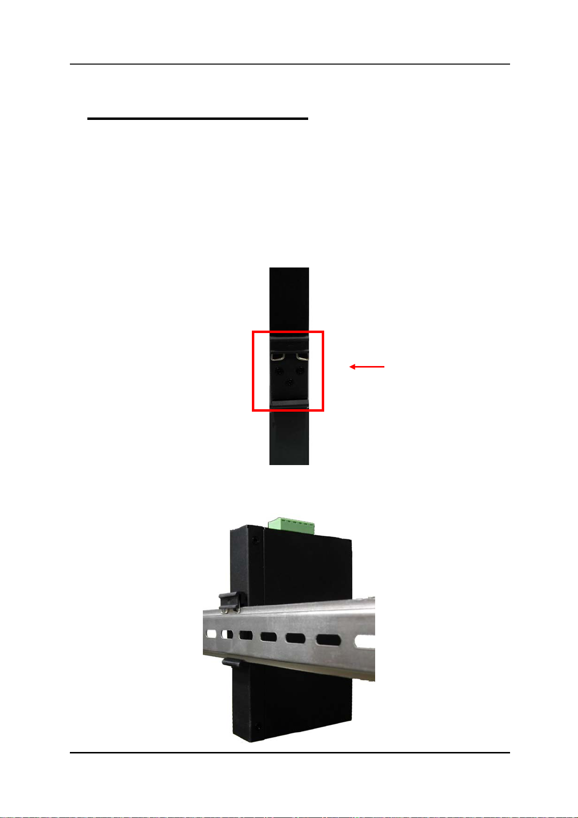
2.1 Installing Switch on DIN-Rail
Each switch has a DIN-Rail kit on rear panel. The DIN-Rail kit helps switch to fix on the
DIN-Rail. It is easy to install the switch on the DIN-Rail:
2.1.1 Mount 505710 / 505628 Series on DIN-Rail
Step 1: Slant the switch and mount the metal spring to DIN-Rail.
\
Metal Spring
Step 2: Push the switch to ward the DIN-Rail until you heard a “click” sound.
INTELLINET NETWORK SOLUTIONS 3
Page 5
505710 / 505628 Series User’s Manual
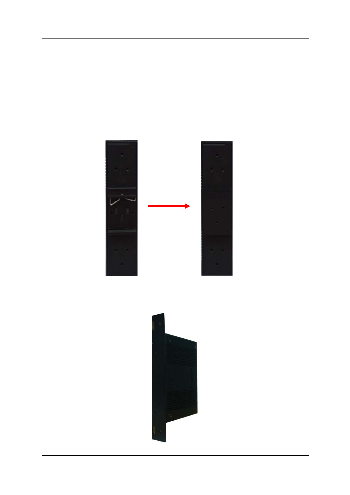
2.2 Wall Mounting Installation
Each switch has another installation method for users to fix the switch. A wall mount panel
can be found in the package. The following steps show how to mount the switch on the wall.
2.2.1 Mount 505710 / 505628 Series on the wall
Step 1: Remove DIN-Rail kit.
\
Step 2: Use 6 screws th at can be found in the p ackage to com bine the wall moun t panel. Just
like the picture shows below:
INTELLINET NETWORK SOLUTIONS 4
Page 6

505710 / 505628 Series User’s Manual
The screws specification shows in the following two pictures. In order to prevent switches
from any damage, the screws should not larger than the size that used in 505710 / 505628
series switches.
Pozidrive
Step 3: Mount the combined switch on the wall.
\
INTELLINET NETWORK SOLUTIONS 5
Page 7

505710 / 505628 Series User’s Manual
Hardware Overview
3.1 Front Panel
The following table describes the labels that stick on the IES-1080 / 1062 series.
Port Description
\
10/100 RJ-45 fast
Ethernet ports
10/100Base-T(X) RJ-45 fast Ethernet ports support
auto-negotiation.
Default Setting :
Speed: auto
Duplex: auto
Flow control : disable
INTELLINET NETWORK SOLUTIONS 6
Page 8

\
505710 / 505628 Series User’s Manual
505710
1. LED for PWR1&PW2. When the PWR1 links, the green led will be light on.
2. LED for Fault Relay. When the power fault occurs, the amber LED will be light on.
3. 10/100Base-T(X) Ethernet ports.
4. LED for Ethernet ports status.
5. Model name
INTELLINET NETWORK SOLUTIONS 7
Page 9

\
505710 / 505628 Series User’s Manual
505628
1. LED for PWR1&PW2. When the PWR1 links, the green led will be light on.
2. LED for Fault Relay. When the power fault occurs, the amber LED will be light on.
3. 10/100Base-T(X) Ethernet ports.
4. LED for Ethernet ports status.
5. Model name
INTELLINET NETWORK SOLUTIONS 8
Page 10

505710 / 505628 Series User’s Manual
3.2 Front Panel LEDs
LED Color Status Description
\
PWR1
PWR2
Fault
10/100Base-T(X) Fast Ethernet ports
LNK / ACT
Green On DC power module 1 activated.
Green On DC power module 2 activated.
Amber On Fault relay. Power failure.
On Port link up.
Green
Blinking Data transmitted.
3.3 Bottom Panel
The bottom panel components of IES-1080 / 1062 Series are sho wn a s belo w:
1. Terminal block includes: PWR1, PWR2 (12-48V DC) and Relay output (1A@24VDC).
2. Power Fault Check
.
INTELLINET NETWORK SOLUTIONS 9
1 2
Page 11

505710 / 505628 Series User’s Manual
3.4 Rear Panel
The components in the rare of IES-1080 / 1062 Series are shown as below:
1. Screw holes for wall mount kit.
2. DIN-Rail kit
\
INTELLINET NETWORK SOLUTIONS 10
Page 12

\
505710 / 505628 Series User’s Manual
Cables
4.1 Ethernet Cables
The 505710 / 505628 series switches have standard Ethernet ports. According to the link
type, the switches use CAT 3, 4, 5,5e UTP cables to connect to an y other netwo rk device (PCs,
servers, switches, routers, or hubs). Please refer to the following table for cable
specifications.
Cable Types and Specifications
Cable Type Max. Length Connector
10BASE-T Cat.3, 4, 5 100-ohm UTP 100 m (328 ft) RJ-45
100BASE-TX Cat.5 100-ohm UTP UTP 100 m (328 ft) RJ-45
4.1.1 100BASE-TX/10BASE-T Pin Assignments
With 100BASE-TX/10BASE-T cable, pins 1 and 2 are used for transmitting data, and
pins 3 and 6 are used for receiving data.
RJ-45 Pin As signments
Pin Number Assignment
1 TD+
2 TD3 RD+
4 Not used
5 Not used
6 RD7 Not used
8 Not used
The 505710 / 505628 Series switches support auto MDI/MDI-X operation. You can
use a straight-through cable to connect PC to switch. The following table below shows
the 10BASE-T/ 100BASE-TX MDI and MDI-X port pin outs.
MDI/MDI-X pins assignment
INTELLINET NETWORK SOLUTIONS 11
Page 13

505710 / 505628 Series User’s Manual
Pin Number MDI port MDI-X port
1 TD+(transmit) RD+(receive)
2 TD-(transmit) RD-(receive)
3 RD+(receive) TD+(transmit)
4 Not used Not used
5 Not used Not used
6 RD-(receive) TD-(transmit)
7 Not used Not used
8 Not used Not used
Note: “+” and “-” signs represent the polarity of the wires that make up each wire pair.
\
Technical Specifications
ORing Switch Model 505628 505710
Physical Ports
10/100 Base-T(X)
Ports in RJ45
Auto MDI/MDIX
Technology
IEEE 802.3 for 10BaseT,
Ethernet Standards
IEEE 802.3u for 100BaseT(X) and 100BaseFX,
IEEE 802.3x for Flow control
MAC Table 1024 MAC addresses
Processing Store-and-Forward
LED indicators
Power indicator Green : Power LED x 2
8 5
Fault indicator Yellow : Indicate PWR1 or PWR2 failure
10/100TX RJ45 port
Green for port Link/Act. Yellow for Duplex/Collision
indicator
Fault contact
Relay Relay output to carry capacity of 1A at 24VDC
INTELLINET NETWORK SOLUTIONS 12
Page 14

505710 / 505628 Series User’s Manual
\
Power
Redundant Input
Dual DC inputs. 12-48VDC on 6-pin terminal block.
power
Power consumption
4 Watts 3.5 Watts
(Typ.)
Overload current
Present
protection
Reverse polarity
Present
protection
Physical
Characteristic
Enclosure IP-30
Dimension (W x D x
33(W) x 95(D) x 144.3(H) mm (1.30 x 3.74 x 5.68 inch.)
H)
Weight (g) 391 382g
Environmental
Storage Temperature -40 to 85oC (-40 to 185oF)
Operating
-40 to 70oC (-40 to 158oF)
Temperature
Operating Humidity 5% to 95% Non-condensing
Regulatory
approvals
EMI FCC Part 15, CISPR (EN55022) class A
EN61000-4-2 (ESD), EN61000-4-3 (RS), EN61000-4-4
EMS
(EFT), EN61000-4-5 (Surge), EN61000-4-6 (CS),
EN61000-4-8, EN61000-4-11
Shock IEC60068-2-27
Free Fall IEC60068-2-32
Vibration IEC60068-2-6
Safety EN60950
INTELLINET NETWORK SOLUTIONS 13
Page 15

\
505710 / 505628 Series User’s Manual
INTELLINET NETWORK SOLUTIONS™ offers a complete line
of active and passive networking products.
Ask your local computer dealer for more information or visit
www.intellinet-network.com
Copyright © INTELLINET NETWORK
All products mentioned are trademarks or registered trademarks of their respective owners.
SOLUTIONS
INTELLINET NETWORK SOLUTIONS 14
 Loading...