

Page 1

Dell™ PowerEdge™ 4820
Installation Guide
Guide d’installation
Installationsanleitung
設置ガイド
Guía de instalación
Page 2

Page 3

Dell™ PowerEdge™ 4820
Installation Guide
Page 4

Notes, Cautions, and Warnings
NOTE: A NOTE indicates important information that helps you make better use
of your computer.
CAUTION: A CAUTION indicates potential damage to hardware or loss of data
if instructions are not followed.
WARNING: A WARNING indicates a potential for property damage,
personal injury, or death.
____________________
Information in this document is subject to change without notice.
© 2010 Dell Inc. All rights reserved.
Reproduction of these materials in any manner whatsoever without the written permission of Dell Inc.
is strictly forbidden
Trademarks used in this text: Dell, the DELL logo, and PowerEdge are trademarks of Dell Inc.
Other trademarks and trade names may be used in this document to refer to either the entities claiming
the marks and names or their products. Dell Inc. disclaims any proprietary interest in trademarks and
trade names other than its own.
January 2010 P/N 21DXJ Rev. A00
Page 5

Contents
Safety Instructions. . . . . . . . . . . . . . . . . . . . . 5
SAFETY: Rack Mounting of Systems
. . . . . . . . . 5
Rack Installation Instructions
Rack Requirements
Before You Begin
Installation Tasks
. . . . . . . . . . . . . . . 6
. . . . . . . . . . . . . . . . . . 6
. . . . . . . . . . . . . . . . . . . 6
. . . . . . . . . . . . . . . . . . . 7
Recommended Tools and Supplies
Removing and Replacing the Rack Doors
Removing and Replacing the Side Panels
Reversing the Front Door (optional)
Securing the Rack Leveling Feet
Installing the Rack Stabilizer Feet
Adjusting the Rack Posts (optional)
Routing Cables
Coupling Two Racks
. . . . . . . . . . . . . . . . . . . 28
. . . . . . . . . . . . . . . . . . . 33
. . . . . . . . . . 8
. . . . . . 8
. . . . . 12
. . . . . . . . 15
. . . . . . . . . . 22
. . . . . . . . . 24
. . . . . . . . 26
Contents 3
Page 6

4 Contents
Page 7

Safety Instructions
Use the following safety guidelines to ensure your own personal safety and
to help protect your system and working environment from potential damage.
For complete safety and regulatory information, see the safety instructions
that shipped with your system. Warranty information might be included in
this document or as a separate document.
SAFETY: Rack Mounting of Systems
Observe the following precautions for rack stability and safety. Also refer to
the rack installation documentation accompanying the system and the rack
for specific caution statements and procedures.
Systems are considered to be components in a rack. "Component" refers to
any system as well as to various peripherals or supporting hardware.
CAUTION: Instructions for Rack-Mounted Systems:
• Your rack kit has been approved only for the rack cabinet provided.
It is your responsibility to ensure that installation of the equipment
into any other rack complies with all applicable standards. Dell disclaims
all liability and warranties with respect to combinations of equipment
with any other rack.
• Before installing your equipment in a rack, install all front and side
stabilizers. Failure to install stabilizers can allow the rack to tip over.
• Always load from the bottom up, and load the heaviest items first.
• Do not overload the AC power supply branch circuit that provides
power to the rack.
• Do not stand or step on any components in the rack.
Installation Guide 5
Page 8
Rack Installation Instructions
This installation guide provides instructions for trained service technicians
installing a 48-unit (U) rack. Information includes assembling the rack,
coupling two 48-U racks, and routing cables through the rack. The 48-U rack
can be installed using the recommended tools.
Before attempting this installation, you should read through this entire
procedure carefully.
Rack Requirements
CAUTION: The 48-U rack meets the specifications of American National Standards
Institute (ANSI)/Electronic Industries Association (EIA) standard ANSI/EIA-310-D-92,
Consumer Electronics Association (CEA) Standard CEA-310-E, International
Electrotechnical Commission (IEC) 297, and Deutsche Industrie Norm (DIN) 41494.
Before You Begin
WARNING: Before you begin installing your rack, carefully read "Important
Safety Information," as well as the safety instructions that came with the rack.
WARNING: When installing multiple systems in a rack, complete all of the
procedures for the current system before attempting to install the next system.
WARNING: Rack cabinets can be extremely heavy and move easily on the
casters. The cabinet has no brakes. Use extreme caution while moving the rack
cabinet. Retract the leveling feet when relocating the rack cabinet. Avoid long or
steep inclines, rough surfaces, or ramps where loss of cabinet control may occur.
Extend the leveling feet for support and to prevent the cabinet from rolling.
WARNING: Avoid rolling the rack cabinet over rough surfaces. Hard impacts to
the casters could cause them to break, and the rack could become unstable and
tip over.
WARNING: Do not attempt to move your rack with components installed. If you
move a fully loaded rack on a slightly uneven floor surface, the rack may become
unstable and tip over.
6 Installation Guide
Page 9
Important Safety Information
Observe the safety precautions in the following subsections when installing
your system in the rack.
WARNING: You must strictly follow the procedures in this document to protect
yourself as well as others who may be involved. Your system may be very large
and heavy, and proper preparation and planning are important to prevent injury to
yourself and to others. This becomes increasingly important when systems are
installed high up in the rack.
Rack Stabilizer Feet
WARNING: Installing systems in a rack without the front and side stabilizer feet
installed could cause the rack to tip over, potentially resulting in bodily injury
under certain circumstances. Therefore, always install the stabilizer feet before
installing components in the rack.
WARNING: After installing systems in a rack, never pull more than one system
out of the rack on its slide assemblies at one time. The weight of more than one
extended system could cause the rack to tip over and cause injury.
The stabilizer feet help prevent the rack from tipping over when a system
or other component is pulled out of the rack with the slide assemblies
fully extended.
Installation Tasks
Installing a rack cabinet involves performing the following tasks:
1
Removing and replacing the rack doors
2
Removing and replacing the side panels
3
Reversing the front door and badge (optional)
4
Securing the leveling feet
5
Installing the stabilizer feet
6
Adjusting the rack posts (optional)
7
Routing cables through the rack
8
Coupling two racks (optional)
Installation Guide 7
Page 10
Recommended Tools and Supplies
You may need the following tools and supplies to install the rack:
• #2 Phillips screwdriver
• Flat head screwdriver
• 12-mm wrench
• Needle-nose pliers
• 4-mm Allen wrench (if you want to reverse the direction that the front
door opens)
• Keys to the rack doors and side panels
• 13-mm wrench (for rack removal from pallet)
• 17-mm wrench (for rack removal from pallet)
Removing and Replacing the Rack Doors
WARNING: Because of the size and weight of the rack cabinet doors,
never attempt to remove or install them by yourself.
WARNING: When storing the doors, lay the doors flat so they cannot fall over and
accidentally injure someone.
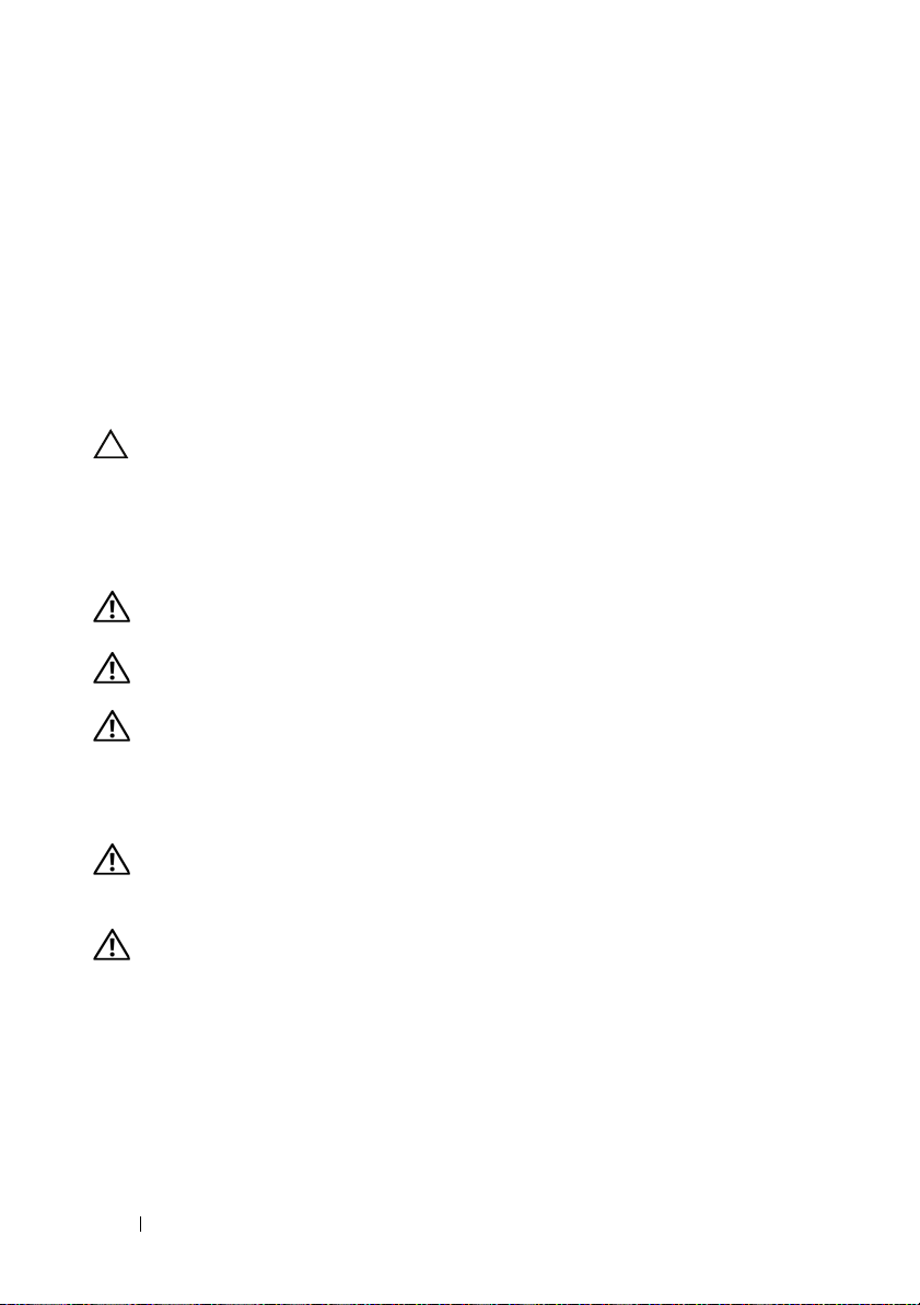
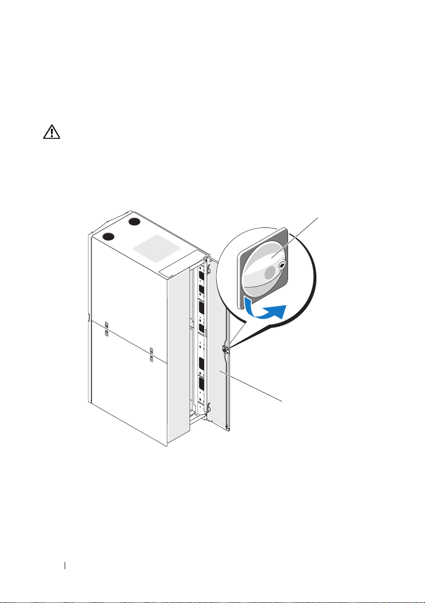
Removing the Front Door
1
Pull the door latch and open the front door all the way (see Figure 1-1).
2
While holding the door, pull the hinge pin upward so that it clears the
door’s hinge-pin housing (see Figure 1-1).
The hinge pin’s retention clip prevents the hinge from being pulled out of
the hinge body.
8 Installation Guide
Page 11
Figure 1-1. Removing the Front Door
1
2
3
4
1 door latch 2 hinge pin
3 hinge body 4 hinge-pin housing
3
While holding the hinge pin out of the door’s hinge-pin housing, pull
the door slightly away from the rack so that the door clears the hinge body.
4
Release the hinge pin.
5
Lift the door upward so that the door clears the bottom hinge post.
WARNING: Due to the size and weight of the door, it is recommended that you lay
the removed door flat with its outer surface facing upward.
6
Lay the door in a safe location with the door’s outer surface facing upward
to help prevent damage to the door’s badge and cosmetic coating.
Installation Guide 9
Page 12
Replacing the Front Door
To replace the front door, perform the steps for removal in reverse.
Opening and Removing the Back Doors
WARNING: Because of the size and weight of the rack cabinet doors, never
attempt to remove or install them by yourself.
1
Turn the door handle and open the back doors (see Figure 1-2).
Figure 1-2. Opening the Back Doors
1
1 door handle 2 back door (2)
10 Installation Guide
2
Page 13
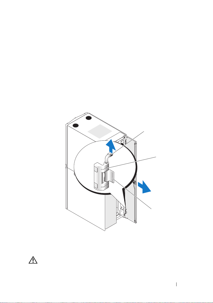
2
Remove the right back door.
a
While supporting the door, pull the pin for the top hinge out of the
door’s hinge-pin housing (see Figure 1-3).
You will hear a click as you pull the pin out of the door’s hinge-pin
housing. The hinge pins are designed to prevent them from being
pulled out of the hinge body.
b
Repeat step a for the bottom hinge.
c
Pull the door away from the rack.
Figure 1-3. Removing the Back Doors
1
2
3
1 hinge pin 2 hinge body
3 hinge-pin housing
WARNING: Due to the size and weight of the door, it is recommended that you lay
the removed door flat with its outer surface facing upward.
Installation Guide 11
Page 14

d
Lay the door in a safe location with the door’s outer surface
facing upward.
Laying the door flat with the outer surface facing upward helps
prevent damage to its cosmetic coating.
e
Repeat step a through step d for the left back door.
Replacing the Back Doors
To replace the back doors, perform the steps for removal in reverse.
Removing and Replacing the Side Panels
CAUTION: For stand-alone racks, reinstalling the side panels is necessary
before running systems in the rack to ensure proper cooling within the rack.
NOTE: You must remove the lower side panels in order to install the side
stabilizer feet.
NOTE: Although removing the side panels is not mandatory for installing
systems in a rack, having the sides open makes it easier to install slide assemblies
and support rails and to reverse the direction that the front door opens.
Removing the Upper Side Panels
1
Pull both latches up and swing the bottom end of the panel away
from the rack.
2
Grasp firmly on each side of the panel.
3
Lift the panel upward until the panel lip clears the top of the rack.
4
Lay the panel in a safe location with the panel’s outer surface facing
upward to help prevent damage to its cosmetic coating.
5
Repeat step 1 through step 4 for the other upper side panel.
Replacing the Upper Side Panels
1
Lift the upper side panel up onto the rack, hooking the panel lip over
the top of the rack (see Figure 1-4).
2
Swing the bottom of the panel downward onto the rack.
3
Press the panel into the rack until both latches lock into place.
12 Installation Guide
Page 15
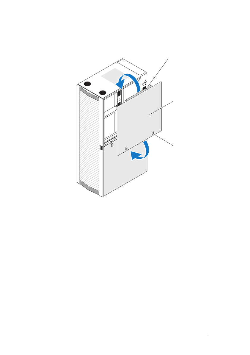
Figure 1-4. Replacing the Upper Side Panels
1
2
3
1 panel lip 2 upper side panel (2)
3 latches (2)
Removing the Lower Side Panels
1
Pull both latches down and allow the side panel to swing outward slightly
at the top.
2
Firmly grasp both sides of the panel.
3
Lift the panel upward until the panel hooks clear the holes in the bottom
of the rack frame.
4
Place the panel in a safe location with the panel’s outer surface facing
upward to help prevent damage to its cosmetic coating.
5
Repeat step 1 through step 4 for the other lower side panel.
Installation Guide 13
Page 16
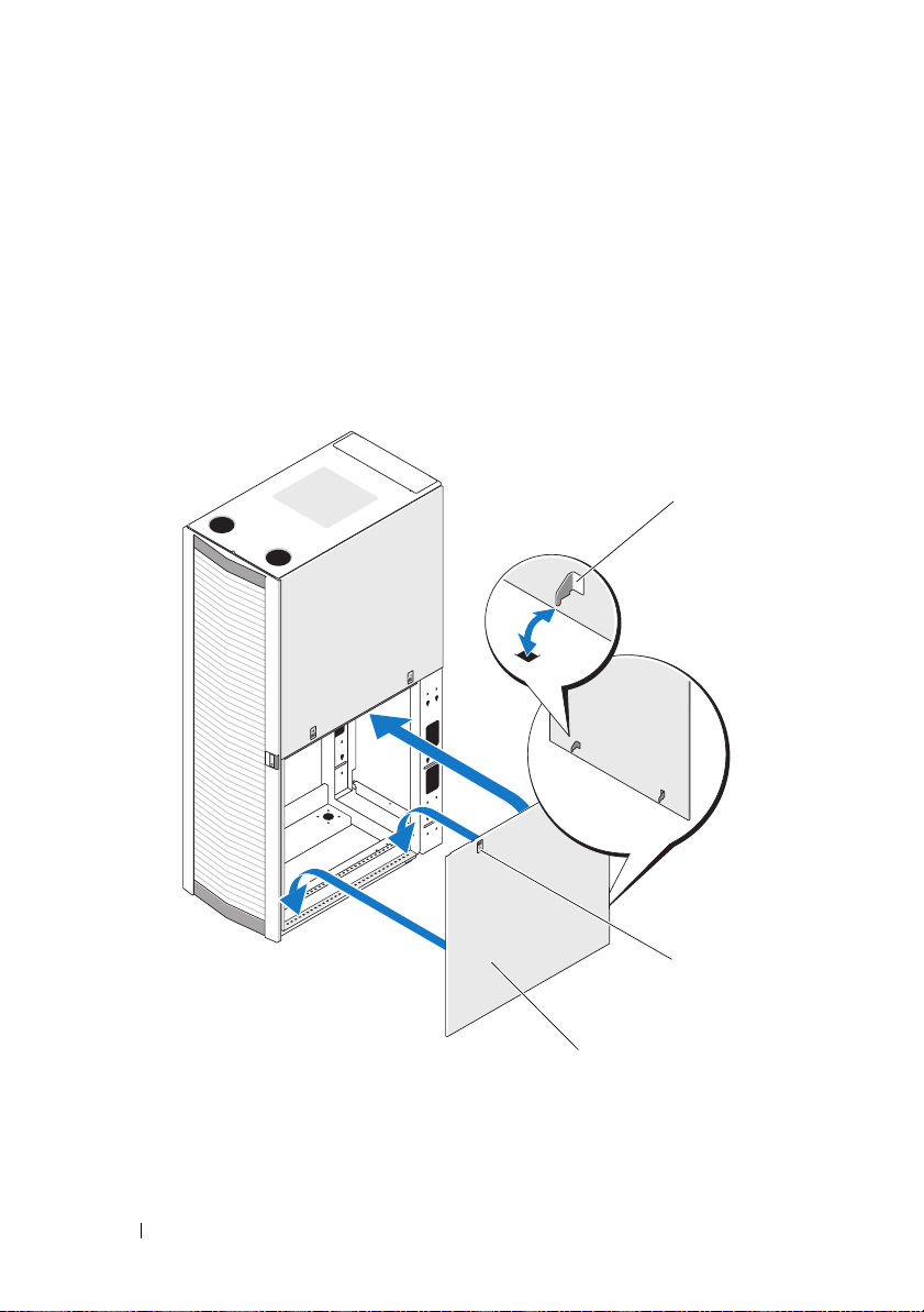
Replacing the Lower Side Panels
1
Lower the panel into the rack, inserting the back panel hook into the back
hole in the bottom of the rack frame and the front hook into the
corresponding hole in the front of the rack frame (see Figure 1-5).
2
Swing the top end of the panel towards the rack.
3
Press the panel into the rack until both latches lock into place.
Figure 1-5. Replacing the Lower Side Panels
1
1 panel hook (2) 2 latch (2)
3 lower side panel (2)
14 Installation Guide
2
3
Page 17

Reversing the Front Door (optional)
NOTE: Use a 4-mm Allen wrench to remove the front-door hinge bodies from the
rack and reinstall them on the side opposite their original positions. You might need
a stepladder in order to access the Allen bolt that secures the top hinge body to the
rack.
To reverse the direction that the front door opens, complete the following
steps:
Remove the front door (see "Removing the Front Door" on page 8).
1
2
Remove the side panels (see "Removing and Replacing the Side Panels" on
page 12).
3
Reverse the top hinge body.
a
Pull the hinge pin upward slightly so that you can access the retention
clip (see Figure 1-6).
b
Using the needle-nose pliers, remove the retention clip, and slide the
hinge pin out of the hinge body.
Installation Guide 15
Page 18
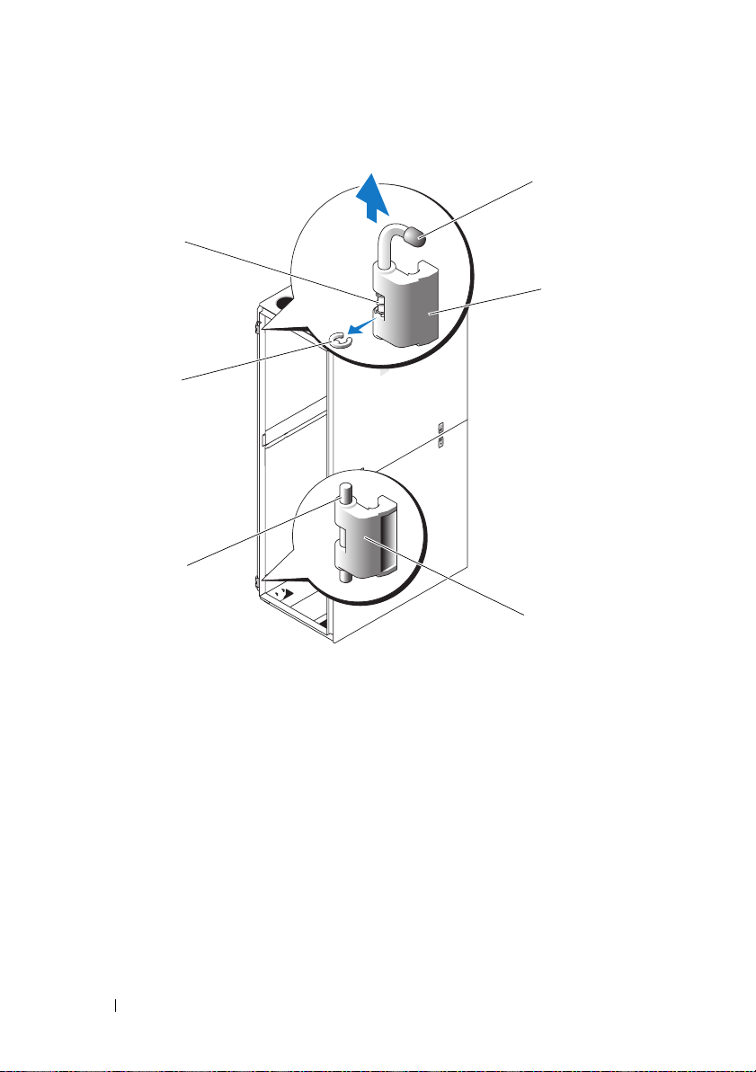
Figure 1-6. Removing the Front-Door Hinges
6
5
4
1
2
3
1 hinge pin 2 top hinge body
3 bottom hinge 4 hinge post
5 retention clip 6 body spring
c
Remove the hinge spring from the hinge body.
d
Place the hinge pin, retention clip, and spring in a safe location.
e
Using the 4-mm Allen wrench, remove the Allen bolts that secure
the hinge body to the rack, and place the bolts with the hinge pin,
retention clip, and body spring.
f
Rotate the hinge body 180 degrees so that the hinge-pin holes are now
on the right side of the hinge body (see Figure 1-7).
16 Installation Guide
Page 19
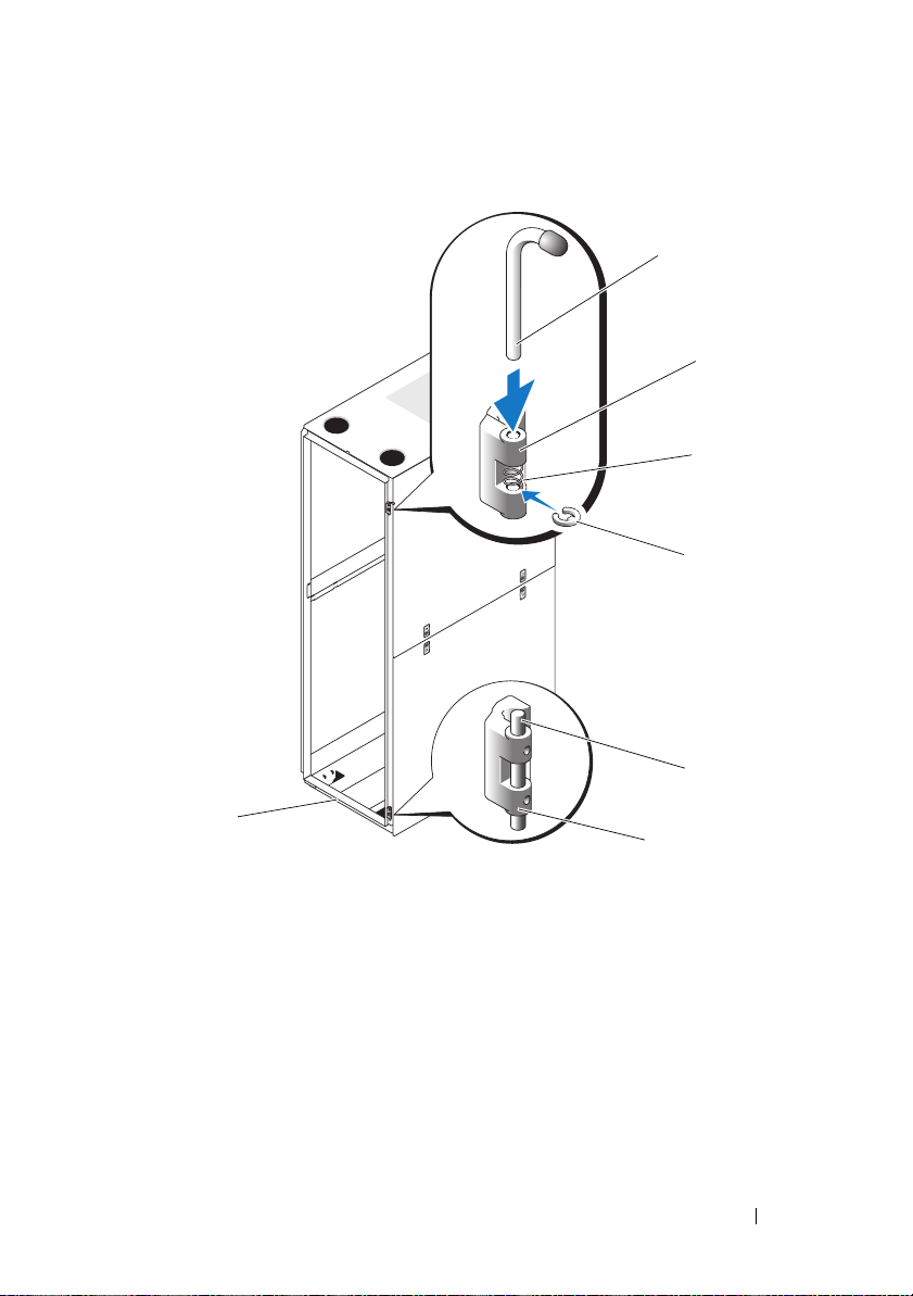
Figure 1-7. Reversing the Top and Bottom Hinges
1
2
3
4
5
7
6
1 hinge pin 2 top hinge body
3 spring 4 retention clip
5 hinge post 6 bottom hinge body
7 front of rack
Installation Guide 17
Page 20

g
Locate the top bolt holes in the right side of the rack, and fasten
the hinge body to the right side of the rack with the Allen bolts.
h
Insert the spring between the top and bottom hinge-pin holes in
the bottom hinge body.
i
Slide the hinge pin into the hinge body.
j
Insert the retention clip through the hinge so that the retention clip
is below the spring.
4
Reverse the bottom hinge body.
a
Remove the Allen bolts that secure the hinge body to the rack,
and place the bolts in a safe location.
b
Rotate the hinge body 180 degrees so that the hinge posts are now on
the other side of the hinge body (see Figure 1-7).
c
Locate the bottom bolt holes in the right side of the rack, and use
the Allen bolts to fasten the hinge body to the right side of the rack.
5
Rotate the front door 180 degrees so that its hinge-pin housings are on
the right side (see Figure 1-8).
18 Installation Guide
Page 21
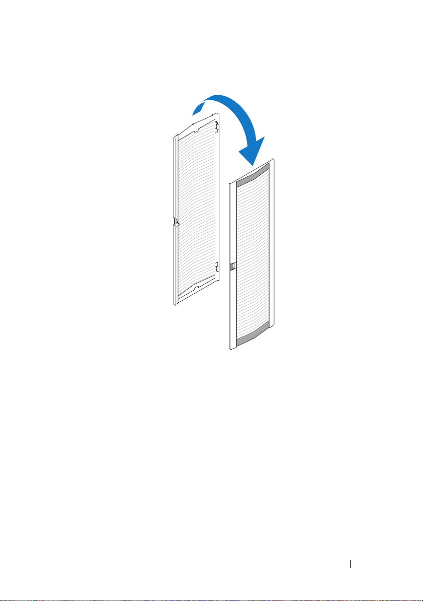
Figure 1-8. Rotate the Front Door
6
Rehang the front door by reversing the steps in "Removing the Front Door"
on page 8.
7
Reverse the lock catch.
a
Unscrew the two Phillips screws that hold the lock catch to the vertical
frame member.
b
Remove the lock catch and rotate it 180 degrees.
c
Reinstall the lock catch on the other rack front vertical frame member
by aligning the holes of the catch with the holes of the frame member
and then reinserting the two Phillips screws. See Figure 1-9.
Installation Guide 19
Page 22
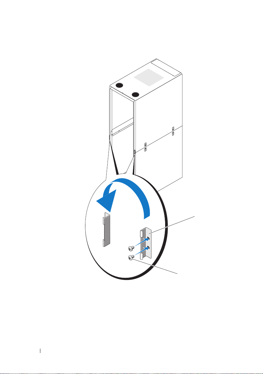
Figure 1-9. Reversing the Front Door Lock Catch
1
1 lock catch 2 screws
8
Reverse the badge on the front door.
a
Open the front door.
b
From inside the door, insert a flat-head screwdriver into the badge
release notch (see Figure 1-10).
20 Installation Guide
2
Page 23
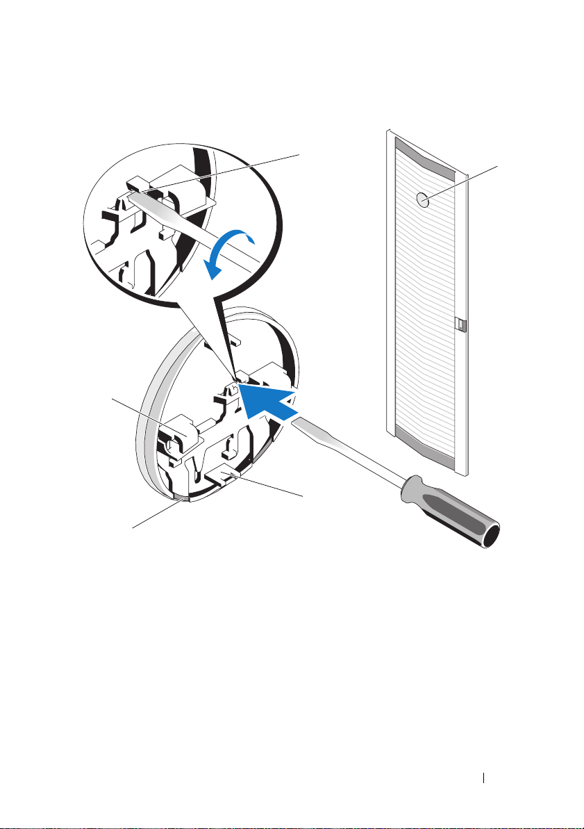
Figure 1-10. Reversing the Front Door Badge
1
5
3
4
2
1 badge release notch 2 front door badge
3 center tab (2) 4 badge retention clip (2)
5 badge hook (2)
c
Push the screwdriver into the notch until it stops and turn
it counter-clockwise.
d
Lift up on the badge and pull it off the door.
e
Rotate the badge 180 degrees so that it will read correctly
when reinstalled.
Installation Guide 21
Page 24
f
Locate the sixth horizontal bar from the top of the door and slide
the badge hooks over it, aligning the center tabs on the badge with
the vertical bar on the door.
g
Push up on the badge retention clips until they are closed and
the badge is secure.
Securing the Rack Leveling Feet
WARNING: Read all statements below before you adjust the leveling feet.
Your rack includes four leveling feet, which are mounted on the corners
of the rack. The leveling feet are designed to align the rack in an upright,
level position when the rack is situated on a slightly uneven floor surface.
Before you install your systems in the rack, deploy and adjust the leveling feet.
When you level your rack, follow these guidelines.
WARNING: When you adjust the leveling feet, ensure that the casters on each
corner of the rack do not rise more than 9.5 mm (3/8 inch) above the floor. If you
exceed 9.5 mm of clearance between the floor and the casters as you adjust the
leveling feet, slowly retract the leveling feet, and then move the rack to another
location that requires minimal adjustments to the leveling feet.
WARNING: Adjust the leveling feet until each leveling foot rests firmly on the
floor. Proper contact with the floor ensures that each leveling foot is supporting
the weight of the rack and prevents the rack from swaying in any direction. If the
leveling feet are not all in firm contact with the floor, the rack can become
unstable and tip over.
WARNING: Do not attempt to move your rack with the leveling feet deployed.
Always retract the leveling feet before moving the rack. Having the leveling feet
deployed when you move the rack may cause the rack to tip over.
WARNING: Always level the rack and install the stabilizing feet before you
install your systems. A fully loaded rack may tip over if your rack is resting on an
uneven floor surface and the leveling and stabilizing feet are not supporting the
weight of the rack.
NOTE: If the rack is not leveled properly, you might not be able to install the
stabilizer feet, which are necessary to prevent the rack from tipping over.
22 Installation Guide
Page 25
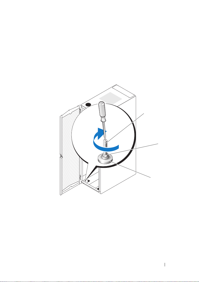
1
Using a screwdriver, lower the leveling foot until it rests on the floor.
2
If you need to lower the foot further, tighten the hex nut clockwise with
a 12-mm wrench (see Figure 1-11).
3
Repeat steps 1 and 2 for the remaining leveling feet.
4
Ensure that the rack is level.
Figure 1-11. Adjusting the Leveling Feet
1
2
1 leveling foot stem 2 hex nut
3 leveling pad
3
Installation Guide 23
Page 26

Installing the Rack Stabilizer Feet
WARNING: Installing systems in a rack without the front and side stabilizer feet
installed could cause the rack to tip over, potentially resulting in bodily injury
under certain circumstances. Therefore, always install the stabilizer feet before
installing components in the rack.
Install stabilizer feet on the rack as follows:
• Install front and side stabilizer feet on a standalone rack.
• Install front stabilizer feet on all racks in a suite, and install left or right
stabilizer feet on the racks at each end of a suite.
Installing the Front Stabilizer Feet
1
Open the front door.
2
Reach into the rack and pull up firmly on each stabilizer to detach them
from the frame.
3
Remove the plastic fasteners attached to the stabilizer feet.
4
Position each front stabilizer foot against the base of the rack frame and
align its holes with the corresponding holes in the frame.
5
Use the provided bolts, washers, and cage nuts to secure each foot to the
rack as shown in Figure 1-12.
24 Installation Guide
Page 27
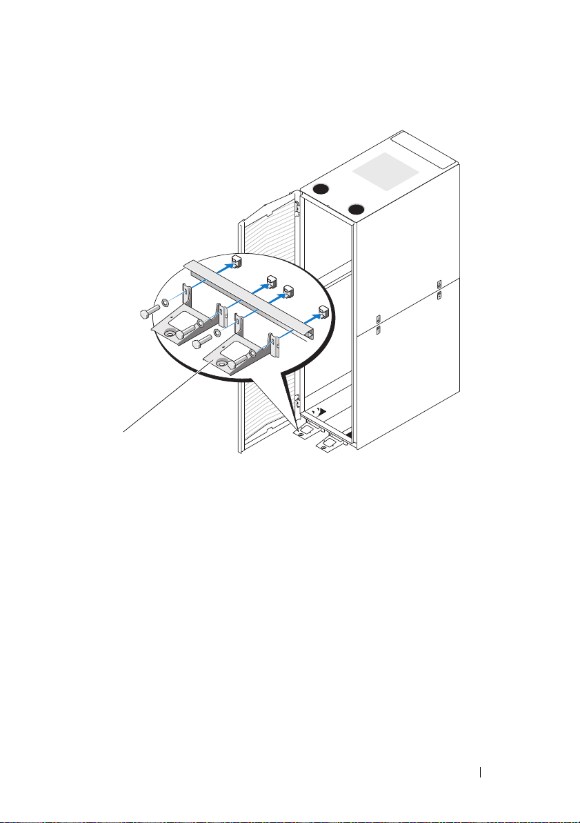
Figure 1-12. Installing the Front Stabilizer Feet
1
1 front stabilizer foot (2)
Installing the Side Stabilizer Feet
1
Remove the lower side panels (see "Removing the Lower Side Panels"
on page 13).
2
On the side of the rack frame’s bottom rail, locate the four holes
(see Figure 1-13).
3
Position each stabilizer foot against the base of the rack frame and align its
holes with the corresponding holes in the frame.
Installation Guide 25
Page 28
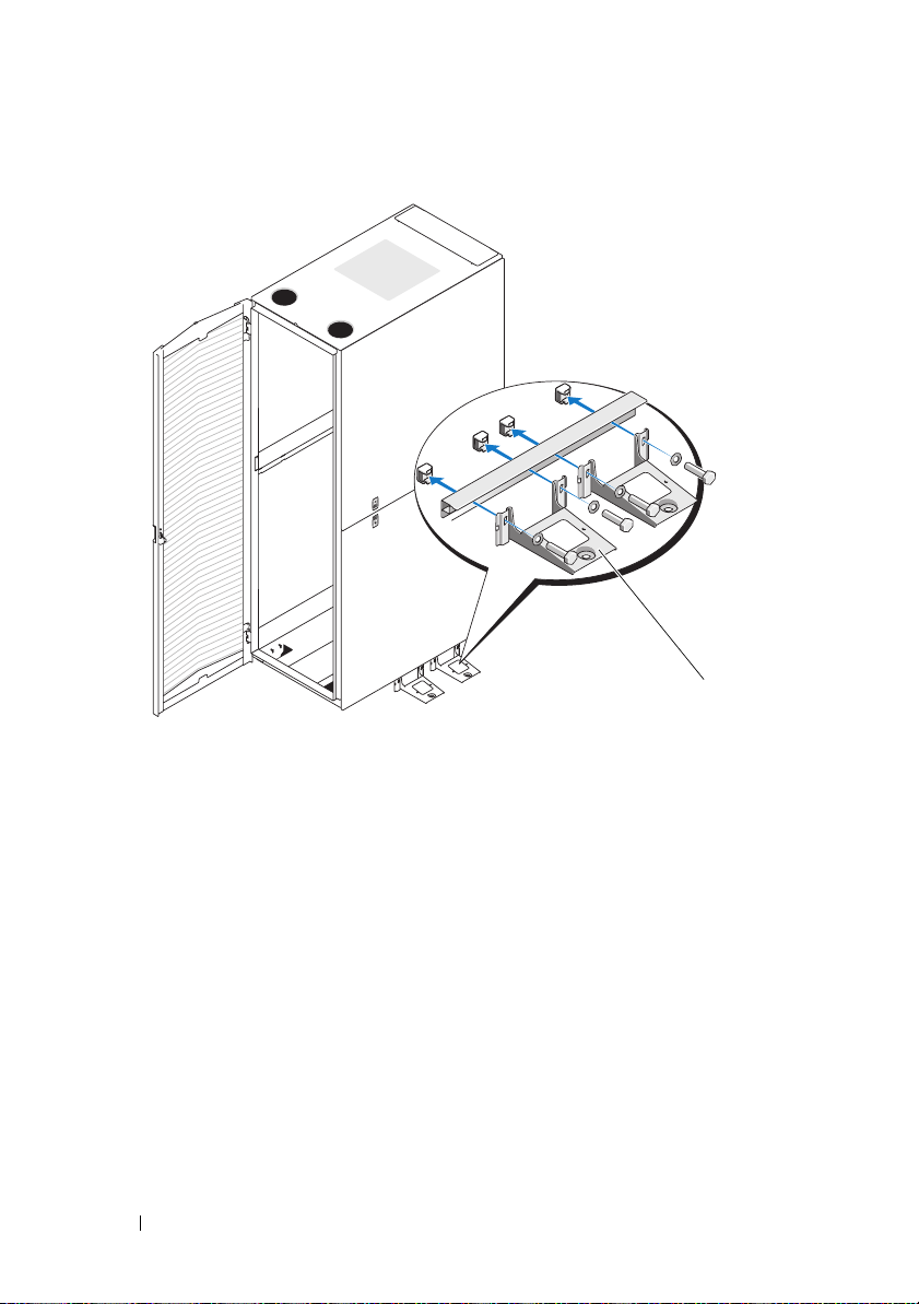
Figure 1-13. Installing the Side Stabilizer Feet
1 side stabilizer foot (2 per side)
1
4
Use the provided bolts, washers, and cage nuts to secure each foot to
the rack as shown in Figure 1-13.
Adjusting the Rack Posts (optional)
The position of the rack posts can be adjusted to accommodate systems
of various depths.
1
Open the rack doors.
2
Remove the screws on the bottom, middle, and top of the post
(see Figure 1-14).
3
Move the post to the desired location inside the side of the rack,
and replace the screws in the corresponding holes.
26 Installation Guide
Page 29
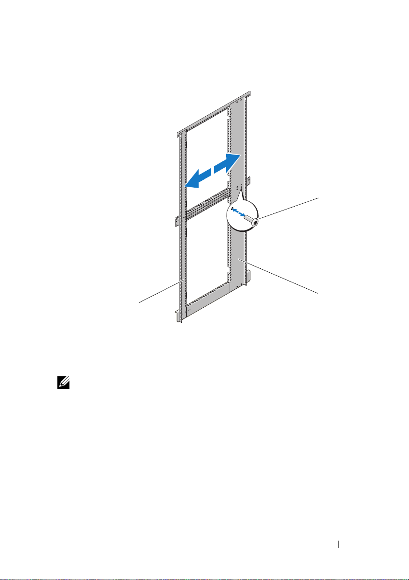
Figure 1-14. Adjusting the Rack Posts
1
3
1 screws 2 back rack post
3 front rack post
NOTE: Unless you need to couple two or more racks, you may now install systems
into the rack. Refer to the white numbered labels on the front and back of the rack
mounting rails for information on installing components in the rack.
Installation Guide 27
2
Page 30

Routing Cables
The 48-U rack offers several features that simplify cable routing
(see Figure 1-15).
• The power distribution unit (PDU) channels in each rack flange allow you
to route power cables to the systems mounted in the rack.
• Cable clips can be mounted in the PDU channels to keep cables out of the
way and help prevent cords from becoming tangled.
You can route cables out of the rack in two ways on a standard configuration:
• Through the cable exit at the bottom of the back doors (see Figure 1-15)
• Through the adjustable cable slot at the top of the rack and into a cable
raceway (see Figure 1-15).
28 Installation Guide
Page 31
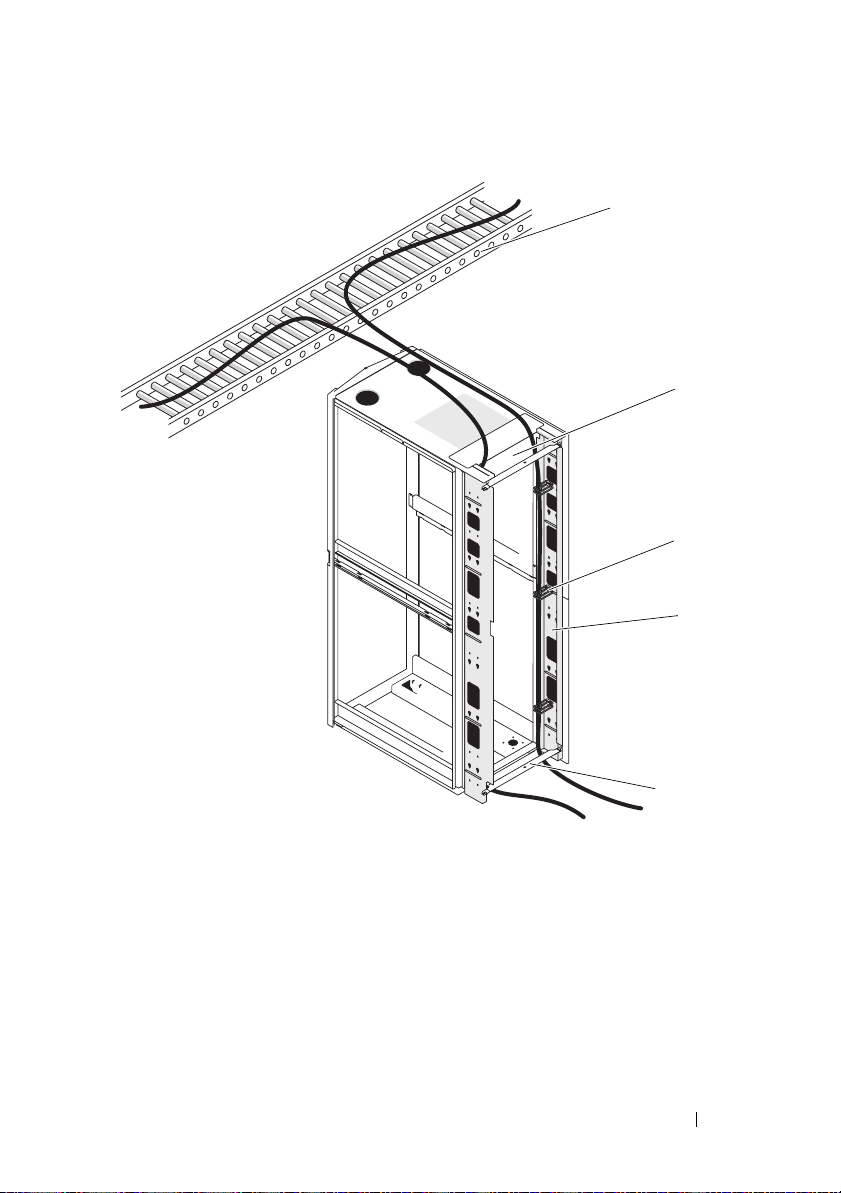
Figure 1-15. Cable-Routing Options
1
2
3
4
1 cable raceway 2 top cable slot
3 cable clips 4 PDU channels (2 per side)
5 bottom cable exit
Installation Guide 29
5
Page 32

Opening and Closing the Top Cable Slot
The top cable slot in the rack can be used for routing cables up to
a cable raceway.
1
Open the back doors.
2
Loosen the wingnuts underneath the cable slot cover (see Figure 1-16).
3
Slide the cable slot cover in the open position towards the front of the
rack.
4
After routing your cables through the top of the rack, close any air gap
in the cable slot by pulling the slot cover towards the back of the rack.
Use the wingnuts to secure the cover.
30 Installation Guide
Page 33

Figure 1-16. Opening and Closing the Top Cable Slot
1
2
1 cable slot cover 2 wingnut (2)
Installation Guide 31
Page 34

Removing and Installing the Back Door Stabilizer Bars
The top and bottom bars used to stabilize the back doors can be removed,
making it easier to route cables through the top and bottom of the rack.
1
Open the back doors.
2
Pull and hold the plungers on each side of the bar, and pull the bar up
and away from the rack (see Figure 1-17).
3
After routing your cables, replace the bars by aligning the tabs on the bars
with the corresponding holes in the rack and pushing in and down until
the plungers lock into place.
Figure 1-17. Removing and Installing the Back Door Stabilizer Bars
1
2
1 back door stabilizer bar (top) 2 plunger (2 per bar)
3 back door stabilizer bar (bottom)
32 Installation Guide
3
Page 35

Coupling Two Racks
WARNING: Because of the size and weight of the rack cabinets, never attempt to
couple two rack cabinets by yourself.
1
Unpack and set up both racks.
2
Unpack the coupling kit, shown in Figure 1-18.
The contents of the rack coupling kit include:
• One gasket strip
• Four coupling brackets
Figure 1-18. Rack Coupling Kit
2
1
1 gasket strip 2 coupling bracket (4)
3
Remove the doors and side panels from both racks. See "Removing the
Front Door" on page 9, "Opening and Removing the Back Doors" on
page 10, and "Removing and Replacing the Side Panels" on page 12.
4
Cut and place a segment of the gasket strip, with its protective backing
removed, on one of the racks along the frame surface to be in contact with
the adjacent rack (see Figure 1-19).
NOTE: It does not matter on which rack you place the gasket strip segments,
as long as they protect both racks from being scratched.
Installation Guide 33
Page 36

Figure 1-19. Installing the Gasket Strips
1
2
1 gasket strip 2 rack frame
34 Installation Guide
Page 37

5
Install the coupling brackets.
a
Position the two racks side by side.
b
Adjust the leveling feet on both racks so that the racks are parallel
and in the same horizontal plane. For instructions, see "Adjusting the
Leveling Feet" on page 23.
c
To install the coupling brackets on the racks, hook the brackets into
the square holes inside and adjacent to the rack posts, and tighten the
brackets using the wingnuts (see Figure 1-20).
Figure 1-20. Coupling Two Racks
1
3
2
1 coupling bracket locations 2 wingnut
3 coupling bracket (4)
Installation Guide 35
Page 38

36 Installation Guide
Page 39

Dell™ PowerEdge™ 4820
Guide d'installation
Page 40

Remarques, précautions et avertissements
REMARQUE : Une REMARQUE indique des informations importantes qui peuvent
vous aider à mieux utiliser votre ordinateur.
PRÉCAUTION : Une PRÉCAUTION vous avertit d'un risque de dommage matériel
ou de perte de données en cas de non-respect des instructions données.
AVERTISSEMENT : Un AVERTISSEMENT vous avertit d'un risque
d'endommagement du matériel, de blessure corporelle ou de mort.
____________________
Les informations contenues dans ce document sont sujettes à modification sans préavis.
© 2010 Dell Inc. Tous droits réservés.
La reproduction de ce document de quelque manière que ce soit sans l'autorisation écrite de Dell Inc.
est strictement interdite.
Marques mentionnées dans ce document : Dell, le logo DELL et PowerEdge sont des marques
de Dell Inc.
D'autres marques commerciales et noms de marque peuvent être utilisés dans ce document pour faire
référence aux entités se réclamant de ces marques et de ces noms ou de leurs produits. Dell Inc. dénie
tout intérêt propriétaire vis-à-vis des marques et des noms de marque autres que les siens.
Janvier 2010 N/P 21DXJ Rév. A00
Page 41

Table des matières
Consignes de sécurité . . . . . . . . . . . . . . . . . . 41
SÉCURITÉ : Montage en rack des systèmes
. . . . 41
Instructions d'installation du rack
Exigences du rack
Avant de commencer
Tâches d'installation
. . . . . . . . . . . . . . . . . 42
. . . . . . . . . . . . . . . . 42
. . . . . . . . . . . . . . . . 43
Outils et fournitures recommandés
Retrait et réinstallation des portes du rack
Retrait et réinstallation
des panneaux latéraux
. . . . . . . . . . . . . . . 48
Inversion du sens d'ouverture
de la porte avant (facultatif)
. . . . . . . . . . . . 52
Fixation des pieds réglables du rack
Installation des stabilisateurs
Réglage des montants (facultatif)
Acheminement des câbles
Couplage de deux racks
. . . . . . . . . . . . . 65
. . . . . . . . . . . . . . . . . 70
. . . . . . . . . . . 42
. . . . . . . . 44
. . . . 44
. . . . . . . . 59
. . . . . . . . . . . 61
. . . . . . . . . 64
Table des matières 39
Page 42

40 Table des matières
Page 43

Consignes de sécurité
Appliquez les consignes de sécurité fournies dans ce guide pour préserver
votre sécurité personnelle et protéger votre système et votre environnement
de travail de tout dommage. Pour des informations complètes sur la sécurité
et les réglementations, voir les consignes de sécurité fournies avec le système.
Les informations de garantie se trouvent dans ce document ou dans un
document distinct.
SÉCURITÉ : Montage en rack des systèmes
Pour garantir la stabilité et la sécurité du rack, prenez les précautions ci-après.
Voir également la documentation d'installation du rack jointe au système et
au rack pour connaître les précautions et les procédures spécifiques.
Les systèmes sont considérés comme étant des composants d'un rack.
Le terme “composant” fait référence à un système ainsi qu'aux différents
périphériques ou au matériel connexe.
PRÉCAUTION : Instructions relatives aux systèmes montés en rack :
• L'utilisation du kit pour rack est approuvée uniquement pour l'armoire
rack fournie. Il vous incombe de vérifier que son installation dans un autre
rack est conforme à l'ensemble des normes en vigueur. Dell décline toute
responsabilité ou garantie en cas d'installation du kit un autre rack.
• Avant d'installer votre kit dans un rack, vous devez au préalable installer
les stabilisateurs avant et latéraux. Autrement, le rack risque de basculer.
• Chargez toujours les composants les plus lourds en premier et de bas en
haut.
• Ne surchargez pas le circuit du bloc d'alimentation en CA qui alimente
le rack.
• Évitez de vous tenir debout sur les composants du rack ou de les piétiner.
Guide d'installation 41
Page 44

Instructions d'installation du rack
Ce guide d'installation contient des instructions destinées aux techniciens
de maintenance qualifiés chargés d'installer un rack à 48 unités (48-U).
Il indique comment assembler le rack, coupler deux racks 48-U et disposer
les câbles dans le rack. Le rack 48-U peut être installé à l'aide des outils
recommandés.
Avant de commencer l'installation, lisez attentivement cette procédure
en entier.
Exigences du rack
PRÉCAUTION : Le rack 48-U est conforme aux spécifications des organismes
suivants : American National Standards Institute (ANSI)/Electronic Industries
Association (EIA), norme ANSI/EIA-310-D-92, Consumer Electronics Association
(CEA), norme CEA-310-E, International Electrotechnical Commission (IEC) 297 et
Deutsche Industrie Norm (DIN) 41494.
Avant de commencer
AVERTISSEMENT : Avant de procéder à l'installation du rack, lisez
attentivement la section “Consignes de sécurité importantes” ainsi que
les consignes de sécurité fournies avec le rack.
AVERTISSEMENT : Si vous installez plusieurs systèmes dans un rack, terminez
toutes les opérations requises pour le système en cours d'installation avant
de passer au suivant.
AVERTISSEMENT : Même si les armoires racks peuvent être extrêmement
lourdes, elles se déplacent facilement sur leurs roulettes. De plus, elles ne
possèdent pas de système de freinage. Procédez avec la plus grande prudence
pour déplacer une armoire rack. Rentrez ses pieds réglables lorsque vous
la changez d'emplacement. Évitez de déplacer l'armoire rack le long de rampes
ou de plans inclinés trop longs ou trop abrupts, sur lesquels elle pourrait vous
échapper. Ressortez les pieds réglables pour supporter l'armoire et l'empêcher
de rouler.
AVERTISSEMENT : Évitez de déplacer l'armoire rack sur des surfaces inégales.
Les secousses risqueraient de briser les roulettes, de déséquilibrer le rack et
de le faire basculer.
AVERTISSEMENT : N'essayez pas de déplacer le rack si des composants y sont
déjà installés. Si vous déplacez un rack entièrement chargé sur une surface
légèrement inégale, il risque de perdre l'équilibrer et de se renverser.
42 Guide d'installation
Page 45

Consignes de sécurité importantes
Respectez les consignes de sécurité décrites dans les sous-sections suivantes
lors de l'installation du système dans le rack.
AVERTISSEMENT : Vous devez respecter à la lettre les procédures décrites dans
ce document afin de préserver votre sécurité et celle des autres intervenants.
Le système peut être très lourd et volumineux. Une préparation et une planification
adéquates sont donc importantes pour éviter tout risque de blessure.
Ces précautions sont d'autant plus importantes lorsque les systèmes sont installés
en hauteur.
Stabilisateurs du rack
AVERTISSEMENT : L'installation de systèmes dans un rack dépourvu
de stabilisateurs avant et latéraux peut provoquer son basculement, et dans
certaines situations, des blessures. C'est pourquoi, il faut toujours monter
les stabilisateurs avant d'installer les composants du rack.
AVERTISSEMENT : Après avoir installé des systèmes dans un rack,
n'en extrayez jamais plus d'un à la fois au moyen des assemblages à glissière.
Le rack risquerait de basculer à cause du poids des systèmes ainsi extraits et
de vous blesser.
Les stabilisateurs permettent d'éviter tout basculement du rack après
extension complète de ses assemblages à glissière en vue du retrait
d'un système ou d'un composant.
Tâches d'installation
Pour installer une armoire rack, vous devez effectuer les opérations suivantes :
Retrait et réinstallation des portes du rack
1
2
Retrait et réinstallation des panneaux latéraux
3
Inversion du sens d'ouverture de la porte avant et du macaron (facultatif)
4
Fixation des pieds réglables
5
Installation des stabilisateurs
6
Réglage des montants (facultatif)
7
Acheminement des câbles dans le rack
8
Couplage de deux racks (facultatif)
Guide d'installation 43
Page 46

Outils et fournitures recommandés
Pour installer le rack, vous pouvez avoir besoin des outils et fournitures
suivants :
• Tournevis cruciforme n° 2
• Tournevis à tête plate
• Clé de 12 mm
• Pince à bec fin
• Clé 6 pans de 4 mm (si vous souhaitez inverser le sens d'ouverture
de la porte avant)
• Clés des portes et des panneaux latéraux du rack
• Clé de 13 mm (pour retirer le rack de la palette)
• Clé de 17 mm (pour retirer le rack de la palette)
Retrait et réinstallation des portes du rack
AVERTISSEMENT : Compte tenu de leur poids et de leur taille, ne retirez
ou n'installez jamais les portes sans l'assistance d'une autre personne.
AVERTISSEMENT : Une fois les portes retirées, posez-les à plat, pour éviter
qu'elles ne se renversent et ne blessent quelqu'un.
Retrait de la porte avant
1
Tirez le loquet et ouvrez complètement la porte avant (voir la figure 1-1).
2
Tout en maintenant la porte, soulevez l'axe de la charnière afin de le
dégager du logement d'axe de charnière de la porte (voir la figure 1-1).
Le clip de retenue de l'axe empêche la charnière de sortir de son logement.
44 Guide d'installation
Page 47

Figure 1-1. Retrait de la porte avant
1
2
3
4
1 loquet 2 axe de la charnière
3 logement de la charnière 4 logement de l'axe de charnière
3
Tout en maintenant l'axe de la charnière hors du logement, tirez
légèrement la porte du rack pour la dégager du logement de la charnière.
4
Lâchez l'axe de la charnière.
5
Soulevez la porte pour la dégager du tourillon inférieur.
AVERTISSEMENT : Compte tenu de la taille et du poids de la porte, il est
recommandé de la poser à plat sur le sol, face externe tournée vers le haut.
6
Posez la porte en lieu sûr en tournant sa face externe vers le haut afin de ne
pas endommager le macaron ou le revêtement.
Guide d'installation 45
Page 48

Réinstallation de la porte avant
Pour réinstaller la porte avant, exécutez la procédure de retrait dans l'ordre
inverse.
Ouverture et retrait des portes arrière
AVERTISSEMENT : Compte tenu de leur poids et de leur taille, ne retirez ou
n'installez jamais les portes sans l'assistance d'une autre personne.
1
Tournez la poignée et ouvrez les portes arrière (voir la figure 1-2).
Figure 1-2. Ouverture des portes arrière
1
1 poignée 2 porte arrière (2)
46 Guide d'installation
2
Page 49

2
Retirez la porte arrière droite.
a
Tout en maintenant la porte, extrayez l'axe de la charnière supérieure
du logement d'axe de charnière de la porte (voir la figure 1-3).
Vous devez normalement entendre un déclic lors de cette opération.
Les axes de charnière sont conçus de façon à ne pas s'extraire
complètement du logement.
b
Répétez l'étape a pour la charnière du bas.
c
Dégagez la porte du rack.
Figure 1-3. Retrait des portes arrière
1
2
3
1 axe de la charnière 2 logement de la charnière
3 logement de l'axe de charnière
AVERTISSEMENT : Compte tenu de la taille et du poids de la porte, il est
recommandé de la poser à plat sur le sol, face externe tournée vers le haut.
Guide d'installation 47
Page 50

d
Posez la porte en lieu sûr, en tournant sa face externe vers le haut.
En procédant ainsi, vous éviterez d'en endommager le revêtement.
e
Répétez la procédure de l'étape a à l'étape d pour retirer la porte arrière
gauche.
Réinstallation des portes arrière
Pour réinstaller les portes arrière, exécutez la procédure de retrait dans l’ordre
inverse.
Retrait et réinstallation des panneaux latéraux
PRÉCAUTION : Pour les racks autonomes, il est indispensable de réinstaller
les panneaux latéraux avant de mettre en marche les systèmes installés dans
le rack pour assurer une ventilation correcte du rack.
REMARQUE : Vous devez retirer les panneaux latéraux inférieurs pour installer
les stabilisateurs latéraux.
REMARQUE : Même s'il n'est pas obligatoire de retirer les panneaux latéraux pour
installer des systèmes dans un rack, il est plus pratique de le faire pour installer
les assemblages à glissière et les rails et inverser l'ouverture des portes.
Retrait des panneaux latéraux supérieurs
1
Tirez les deux loquets vers le haut et dégagez la partie inférieure
du panneau.
2
Tenez fermement le panneau par ses côtés.
3
Soulevez le panneau jusqu'à ce que sa lèvre se dégage de la partie
supérieure du rack.
4
Posez le panneau en lieu sûr en tournant sa face externe vers le haut afin
de ne pas en endommager le revêtement.
5
Répétez la procédure de l'étape 1 à l'étape 4 pour retirer l'autre panneau
latéral supérieur.
48 Guide d'installation
Page 51

Réinstallation des panneaux latéraux supérieurs
1
Soulevez le panneau latéral supérieur et accrochez sa lèvre sur la partie
supérieure du rack (voir la figure 1-4).
2
Faites basculer la partie inférieure du panneau vers le rack.
3
Enfoncez le panneau dans le rack jusqu'à ce que les deux loquets
s'enclenchent.
Figure 1-4. Réinstallation des panneaux latéraux supérieurs
1
2
3
1 lèvre 2 panneau latéral supérieur (2)
3 loquets (2)
Guide d'installation 49
Page 52

Retrait des panneaux latéraux inférieurs
1
Tirez les deux loquets vers le bas pour permettre la partie supérieure
du panneau latéral de basculer légèrement vers l'extérieur.
2
Tenez fermement le panneau par ses côtés.
3
Soulevez le panneau de façon à en dégager les crochets des orifices
de la base du cadre du rack.
4
Posez le panneau en lieu sûr en tournant sa face externe vers le haut afin
de ne pas en endommager le revêtement.
5
Répétez la procédure de l'étape 1 à l'étape 4 pour retirer l'autre panneau
latéral inférieur.
Réinstallation des panneaux latéraux inférieurs
1
Abaissez le panneau dans le rack, en introduisant le crochet du panneau
arrière dans l'orifice arrière de la base du cadre du rack et le crochet avant
dans l'orifice correspondant à l'avant du cadre du rack (voir la figure 1-5).
2
Faites basculer la partie supérieure du panneau vers le rack.
3
Enfoncez le panneau dans le rack jusqu'à ce que les deux loquets
s'enclenchent.
50 Guide d'installation
Page 53

Figure 1-5. Réinstallation des panneaux latéraux inférieurs
1
2
1 crochet (2) 2 loquet (2)
3 panneau latéral inférieur (2)
Guide d'installation 51
3
Page 54

Inversion du sens d'ouverture de la porte avant (facultatif)
REMARQUE : Utilisez une clé 6 pans de 4 mm pour retirer les logements
de charnières de la porte avant du rack et les réinstaller sur le côté opposé.
Un escabeau peut être nécessaire pour accéder au boulon Allen qui fixe
le logement de la charnière supérieure au rack.
Pour inverser le sens d'ouverture de la porte avant, procédez comme suit :
Retirez la porte avant (voir la “Retrait de la porte avant” à la page 44).
1
2
Retirez les panneaux latéraux (voir la “Retrait et réinstallation des
panneaux latéraux” à la page 48).
3
Inversez le logement de la charnière supérieure.
a
Tirez légèrement l'axe vers le haut pour accéder au clip de retenue
(voir la figure 1-6).
b
À l'aide de la pince à bec fin, retirez le clip de retenue et extrayez l'axe
du logement de la charnière.
52 Guide d'installation
Page 55

Figure 1-6. Retrait des charnières de la porte avant
6
5
4
1
2
3
1 axe de la charnière 2 logement de la charnière supérieure
3 charnière inférieure 4 tourillon
5 clip de fixation 6 ressort
c
Retirez le ressort de la charnière de son logement.
d
Rangez en lieu sûr l'axe, le clip de retenue et le ressort.
e
À l'aide de la clé 6 pans de 4 mm, retirez les boulons Allen qui fixent
le logement de la charnière au rack et rangez-les avec l'axe, le clip
de retenue et le ressort.
f
Faites pivoter le logement de la charnière de 180 degrés pour amener
les orifices de l'axe sur la partie droite du logement de la charnière
(voir la figure 1-7).
Guide d'installation 53
Page 56

Figure 1-7. Inversion des charnières supérieure et inférieure
1
2
3
4
5
7
6
1 axe de la charnière 2 logement de la charnière supérieure
3 ressort 4 clip de fixation
5 tourillon 6 logement de la charnière inférieure
7 avant du rack
54 Guide d'installation
Page 57

g
Repérez les orifices du boulon supérieur sur la partie droite du rack et
fixez le logement de la charnière à cet endroit à l'aide des boulons
Allen.
h
Insérez le ressort entre les orifices d'axe supérieur et inférieur,
à l'intérieur du logement de la charnière inférieure.
i
Insérez l'axe dans le logement de la charnière.
j
Insérez le clip de retenue en le faisant passer dans la charnière de façon
à le placer sous le ressort.
4
Inversez le logement de la charnière inférieure.
a
Retirez les boulons Allen qui fixent le logement de la charnière au rack
et rangez-les en lieu sûr.
b
Faites pivoter le logement de la charnière de 180 degrés pour amener
les tourillons à la droite du logement (voir la figure 1-7).
c
Repérez les trous de boulons inférieurs sur le côté droit du rack et fixez
le logement de la charnière à cet endroit à l'aide des boulons Allen.
5
Faites pivoter la porte de 180 degrés pour amener les logements d'axe sur
le côté droit (voir la figure 1-8).
Guide d'installation 55
Page 58

Figure 1-8. Rotation de la porte avant
6
Réinstallez la porte avant en exécutant dans l'ordre inverse les étapes
de la section “Retrait de la porte avant” à la page 44.
7
Inversez le butoir de verrouillage.
a
Dévissez les deux vis cruciformes n° 1 qui maintiennent le butoir
de verrouillage sur le cadre vertical du rack.
b
Retirez le butoir de verrouillage et faites-le pivoter de 180 degrés.
c
Réinstallez le butoir de verrouillage sur l'autre cadre vertical avant
du rack en alignant les trous du butoir avec ceux de la structure et
en réinsérant les deux vis cruciformes n°1. Voir figure 1-9.
56 Guide d'installation
Page 59

Figure 1-9. Inversion du sens d'ouverture de la porte avant
1
1 butoir de verrouillage 2 vis
8
Inversez le macaron sur la porte avant.
a
Ouvrez la porte avant.
b
De l'intérieur de la porte, insérez un tournevis à tête plate dans
l'encoche de dégagement du macaron (voir la figure 1-10).
2
Guide d'installation 57
Page 60

Figure 1-10. Inversion du sens du macaron de la porte avant
1
5
3
4
2
1 encoche de dégagement du macaron 2 macaron de la porte avant
3 languette centrale (2) 4 clip de retenue du macaron (2)
5 crochet du macaron (2)
58 Guide d'installation
Page 61

c
Poussez le tournevis à fond dans l'encoche de dégagement,
puis tournez-le dans le sens contraire des aiguilles d'une montre.
d
Soulevez le macaron et dégagez-le de la porte.
e
Faites pivoter le macaron de 180 degrés afin de le remettre à l'endroit.
f
Repérez la sixième barre horizontale en partant du haut de la porte et
accrochez-y les crochets du macaron, en alignant les languettes
centrales du macaron sur la barre verticale de la porte.
g
Appuyez sur les clips de retenue du macaron jusqu'à leur fermeture.
Fixation des pieds réglables du rack
AVERTISSEMENT : Lisez toutes les instructions avant d'ajuster les pieds
réglables.
Votre rack est équipé de quatre pieds réglables, un à chaque coin.
Ils permettent à maintenir le rack parfaitement droit, même s'il est installé
sur une surface légèrement inégale. Avant d'installer vos systèmes dans le
rack, déployez et ajustez les pieds réglables. Pour mettre le rack de niveau,
respectez les consignes suivantes.
AVERTISSEMENT : Lorsque vous réglez les pieds, vérifiez que les roulettes à
chaque coin du rack ne s'élèvent pas de plus de 9,5 mm au-dessus du plancher.
Si le dégagement entre le plancher et les roulettes est supérieure à 9,5 mm,
rentrez lentement les pieds, puis déplacez le rack vers un endroit ne nécessitant
qu'un ajustement minimal des pieds réglables.
AVERTISSEMENT : Réglez chaque pied jusqu'à ce qu'il repose fermement sur
le sol. Ceci permet de supporter le poids du rack et l'empêche de vaciller.
Si les pieds réglables ne touchent pas carrément le sol, le rack risque de perdre
l'équilibre et de basculer.
AVERTISSEMENT : N'essayez pas de déplacer le rack quand les pieds réglables
sont déployés. Rentrez toujours les pieds réglables avant de déplacer le rack.
Il risque de se reverser si ses pieds sont déployés lorsque vous le déplacez.
AVERTISSEMENT : Avant d'installer vos systèmes, vous devez toujours mettre
de niveau le rack et installer les stabilisateurs. Un rack entièrement chargé risque
de se renverser s'il est sur une surface inégale et que son poids ne repose pas sur
ses stabilisateurs et pieds réglables.
REMARQUE : Si rack n'est pas correctement de niveau, vous ne pourrez pas
installer les stabilisateurs qui lui évitent de basculer.
Guide d'installation 59
Page 62

1
À l'aide d'un tournevis, abaissez le pied réglable jusqu'à ce qu'il touche
le sol.
2
Pour abaisser davantage le pied, resserrez l'écrou 6 pans à l'aide d'une clé
de 12 mm (voir la figure 1-11).
3
Répétez les étapes 1 et 2 pour les autres pieds réglables.
4
Vérifiez que le rack est bien de niveau.
Figure 1-11. Ajustement des pieds réglables
1
2
1 axe du pied réglable 2 écrou 6 pans
3patin
60 Guide d'installation
3
Page 63

Installation des stabilisateurs
AVERTISSEMENT : L'installation de systèmes dans un rack dépourvu
de stabilisateurs avant et latéraux peut provoquer son basculement, et dans
certaines situations, des blessures. C'est pourquoi, il faut toujours monter
les stabilisateurs avant d'installer les composants du rack.
Installez les stabilisateurs sur le rack en procédant comme suit :
• Sur un rack autonome, installez les stabilisateurs avant et latéraux.
• Sur des racks couplés, installez les stabilisateurs avant sur chaque rack,
et les stabilisateurs gauches ou droits sur les deux racks situés aux
extrémités.
Installation des stabilisateurs avant
1
Ouvrez la porte avant.
2
Passez la main dans le rack et tirez fermement les stabilisateurs un à un
pour les dégager du cadre.
3
Retirez les cales en plastique des stabilisateurs.
4
Placez chaque stabilisateur avant contre la base du cadre du rack et
alignez-en les trous avec ceux du cadre.
5
Utilisez les boulons, rondelles et écrous à cage fournis pour fixer chaque
stabilisateur au rack, comme l'indique la figure 1-12.
Guide d'installation 61
Page 64

Figure 1-12. Installation des stabilisateurs avant
1
1 stabilisateur avant (2)
Installation des stabilisateurs latéraux
1
Retirez les panneaux latéraux inférieurs (voir “Retrait des panneaux
latéraux inférieurs” à la page 50).
2
Sur le côté du rail inférieur du cadre du rack, repérez les quatre trous
(voir la figure 1-13).
3
Placez chaque stabilisateur contre la base du cadre du rack et alignez-en
les trous avec ceux du cadre.
62 Guide d'installation
Page 65

Figure 1-13. Installation des stabilisateurs latéraux
1 stabilisateur latéral (2 par côté)
1
4
Utilisez les boulons, rondelles et écrous à cage fournis pour fixer chaque
stabilisateur au rack, comme l'indique la figure 1-13.
Guide d'installation 63
Page 66

Réglage des montants (facultatif)
Vous pouvez régler la position des montants pour accueillir des systèmes
de profondeurs diverses.
Ouvrez les portes du rack.
1
2
Retirez les vis inférieure, centrale et supérieure du montant
(voir la figure 1-14).
3
Positionnez le montant à l'endroit voulu à l'intérieur du rack, puis remettez
les vis en place.
Figure 1-14. Réglage des montants
1
3
1 vis 2 montant arrière du cadre
3 montant avant du cadre
REMARQUE : Si vous n'envisagez pas de coupler votre rack, vous pouvez à
présent y installer des systèmes. Les étiquettes blanches numérotées, apposées à
l'avant et à l'arrière des rails de fixation, fournissent des informations sur
l'installation de composants dans le rack.
64 Guide d'installation
2
Page 67

Acheminement des câbles
Le rack 48-U comporte plusieurs éléments qui simplifient l'acheminement
des câbles (voir la figure 1-15).
• Les quatre canaux d'unité de distribution de l'alimentation (PDU)
de chaque collerette du rack permettent d'acheminer les câbles
d'alimentation des systèmes montés.
• Vous pouvez installer des serre-câbles sur les canaux PDU pour éviter que
les câbles n'encombrent le rack ou qu'ils ne s'emmêlent.
Dans une configuration standard, vous pouvez acheminer les câbles hors
du rack de deux façons :
• Via la sortie câbles située au bas des portes arrière (voir la figure 1-15)
• Via la sortie câbles réglable située en haut du rack et dans un chemin
de câbles (voir la figure 1-15).
Guide d'installation 65
Page 68

Figure 1-15. Options d'acheminement des câbles
1
2
3
4
1 chemin de câbles 2 sortie câbles supérieure
3 serre-câbles 4 canaux d'unité de distribution
de l'alimentation (2 par côté)
5 sortie câbles inférieure
66 Guide d'installation
5
Page 69

Ouverture et fermeture de la sortie câbles supérieure
Vous pouvez utiliser la sortie câbles supérieure pour acheminer les câbles vers
un chemin de câbles.
1
Ouvrez les portes arrière.
2
Dévissez les écrous à oreilles situés sous le couvercle de la sortie câbles
(voir la figure 1-16).
3
Faites glisser le couvercle vers l'avant du rack pour l'ouvrir.
4
Après avoir acheminé les câbles vers le haut du rack, refermez le couvercle
en le faisant glisser vers l'arrière du rack. Fixez le couvercle à l'aide des
écrous à oreilles.
Guide d'installation 67
Page 70

Figure 1-16. Ouverture et fermeture de la sortie câbles supérieure
1
2
1 couvercle de la sortie câbles 2 écrou à oreilles (2)
68 Guide d'installation
Page 71

Retrait et installation des barres de stabilisation de la porte arrière
Vous pouvez retirer les barres inférieure et supérieure de stabilisation
des portes arrière, pour faciliter l'acheminement des câbles.
1
Ouvrez les portes arrière.
2
Tirez les tiges de chaque côté de la barre, puis soulevez la barre pour
la dégager du rack (voir la figure 1-17).
3
Après avoir acheminé les câbles, remettez les barres en place en alignant
leurs languettes avec les trous correspondant du rack. Poussez ensuite
les barres jusqu'à ce que les tiges s'enclenchent.
Figure 1-17. Retrait et installation des barres de stabilisation de la porte arrière
1
2
1 barre de stabilisation de la porte
arrière (haut)
3 barre de stabilisation de la porte
arrière (bas)
3
2 tige (2 par barre)
Guide d'installation 69
Page 72

Couplage de deux racks
AVERTISSEMENT : Compte tenu du poids et de la taille des armoires racks,
ne couplez jamais deux racks sans vous faire assister.
1
Retirez les deux racks de leur emballage et installez-les.
2
Retirez le kit de couplage de son emballage (voir la figure 1-18).
Ce kit contient :
• Un joint de garniture
• Quatre supports de couplage
Figure 1-18. Kit de couplage du rack
2
1
1 joint de garniture 2 support de couplage (4)
3
Retirez les portes et les panneaux latéraux des deux racks. Voir “Retrait de
la porte avant” à la page 45, “Ouverture et retrait des portes arrière” à la
page 46 et “Retrait et réinstallation des panneaux latéraux” à la page 48.
4
Coupez un morceau de joint de garniture et retirez l'adhésif de protection.
Appliquez la bande sur l'un des racks, le long de la surface du cadre devant
être en contact avec le rack adjacent (voir la figure 1-19).
REMARQUE : Le choix du rack sur lequel vous placez le joint n'a pas
d'importance, dès lors qu'il permet d'éviter les rayures.
70 Guide d'installation
Page 73

Figure 1-19. Mise en place des joints de garniture
1
2
1 joint de garniture 2 cadre du rack
Guide d'installation 71
Page 74

5
Fixez les supports de couplage.
a
Positionnez les deux racks côte à côte.
b
Ajustez les pieds réglables pour que les racks soient parallèles et sur
le même plan horizontal. Pour les instructions, voir “Ajustement des
pieds réglables” à la page 60.
c
Pour installer les supports de couplage sur les racks, accrochez
les supports dans les trous carrés situés à l'intérieur des racks, à côté
des montants, puis vissez les supports à l'aide des écrous à oreilles
(voir la figure 1-20).
Figure 1-20. Couplage de deux racks
1
3
1 emplacement des supports
de couplage
3 support de couplage (4)
72 Guide d'installation
2
2 écrous à oreilles
Page 75

Dell™ PowerEdge™ 4820
Installationsanleitung
Page 76

Anmerkungen, Vorsichtshinweise
und Warnungen
ANMERKUNG: Eine ANMERKUNG macht auf wichtige Informationen
aufmerksam, mit denen Sie das System besser einsetzen können.
VORSICHTSHINWEIS: Ein VORSICHTSHINWEIS macht aufmerksam auf
mögliche Beschädigung der Hardware oder Verlust von Daten bei Nichtbefolgung
von Anweisungen.
WARNUNG: Durch eine WARNUNG werden Sie auf Gefahrenquellen
hingewiesen, die materielle Schäden, Verletzungen oder sogar den Tod von
Personen zur Folge haben können.
____________________
Irrtümer und technische Änderungen vorbehalten.
© 2010 Dell Inc. Alle Rechte vorbehalten.
Eine Vervielfältigung oder Wiedergabe dieser Materialien in jeglicher Weise ohne vorherige
schriftliche Genehmigung von Dell Inc. ist strengstens untersagt.
Marken in diesem Text: Dell, das DELL Logo und PowerEdge sind Marken von Dell Inc.
Alle anderen in dieser Dokumentation genannten Marken und Handelsbezeichnungen sind Eigentum
der entsprechenden Hersteller und Firmen. Dell Inc. erhebt keinen Anspruch auf Marken und
Handelsbezeichnungen mit Ausnahme der eigenen.
Januar 2010 Teilenr. 21DXJ Rev. A00
Page 77

Inhalt
Sicherheitshinweise. . . . . . . . . . . . . . . . . . . 77
SICHERHEIT: Einbauen von Systemen
im Rack
. . . . . . . . . . . . . . . . . . . . . . . 77
Anleitung für die Rackmontage
Rackanforderungen
Bevor Sie beginnen
Ablauf der Installation
. . . . . . . . . . . . . 78
. . . . . . . . . . . . . . . . 78
. . . . . . . . . . . . . . . . . 78
. . . . . . . . . . . . . . . 79
Empfohlene Werkzeuge und Zubehör
Entfernen und Installieren der Racktüren
Entfernen und Installieren der Seitenteile
Umgekehrtes Einbauen
der vorderen Tür (optional)
. . . . . . . . . . . . . 88
Einstellen der höhenverstellbaren Rackfüße
Anbringen der Stabilisatoren
. . . . . . . . . . . . 98
Anpassen der Rackstützen (optional)
Verlegen der Kabel
Verbinden von zwei Racks
. . . . . . . . . . . . . . . . . 102
. . . . . . . . . . . . . . . 107
. . . . . . . 80
. . . . . 80
. . . . . 84
. . . 95
. . . . . . . 101
Inhalt 75
Page 78

76 Inhalt
Page 79

Sicherheitshinweise
Beachten Sie die nachfolgenden Sicherheitshinweise, um Ihre eigene
Sicherheit zu gewährleisten und eine Beschädigung des Systems und
der Arbeitsumgebung zu vermeiden. Die vollständigen wichtigen
Informationen zu Sicherheitsanforderungen und Betriebsvorschriften finden
Sie in den Sicherheitshinweisen, die Sie mit dem System erhalten haben.
Die Garantieinformationen befinden sich entweder dort oder in einem
gesonderten Dokument.
SICHERHEIT: Einbauen von Systemen im Rack
Folgende Vorsichtsmaßnahmen dienen der Stabilität und Sicherheit
des Racks. Spezifische Vorsichtshinweise und Sicherheitsmaßnahmen finden
Sie auch in der mit dem System gelieferten Dokumentation zur Rackinstallation.
Systeme gelten als Komponenten in einem Rack. Der Begriff „Komponente“
bezieht sich auf alle Systeme sowie auf verschiedene Peripheriegeräte oder
unterstützende Hardware.
VORSICHTSHINWEIS: Anleitungen für rackmontierte Systeme:
• Das Rack-Kit ist nur für den gelieferten Rackschrank zugelassen. Es liegt
in Ihrer Verantwortung, dafür zu sorgen, dass die Installation des Systems
in einem anderen Rack allen zutreffenden Standards entspricht.
Dell übernimmt keinerlei Haftung und Gewährleistung bezüglich
der Kombination des Systems mit einem anderen Rack.
• Bringen Sie alle vorderen und seitlichen Stabilisatoren an, bevor Sie
das System in einem Rack installieren. Wenn Sie die Stabilisatoren nicht
anbringen, kann das Rack umkippen.
• Setzen Sie die Komponenten immer von unten nach oben ein und setzen
Sie immer zuerst die schwersten Elemente ein.
• Überlasten Sie nicht den Wechselstromkreis für das Rack.
• Stellen Sie sich nicht auf Komponenten im Rack und treten Sie nicht
darauf.
Installationsanleitung 77
Page 80

Anleitung für die Rackmontage
Diese Installationsanleitung enthält Anweisungen für geschulte Servicetechniker zur Installation eines 42U-Racks (Rack mit 42 Einheiten).
Sie erfahren unter anderem, wie Sie das Rack montieren, zwei 42-U-Racks
miteinander verbinden und Kabel durch das Rack verlegen. Das 48-U-Rack
kann mit den empfohlenen Werkzeugen installiert werden.
Bevor Sie mit der Installation beginnen, lesen Sie diese gesamte Vorgehensweise sorgfältig durch.
Rackanforderungen
VORSICHTSHINWEIS: Das 48-U-Rack erfüllt die Spezifikationen American
National Standards Institute (ANSI)/Electronic Industries Association (EIA)
ANSI/EIA-310-D-92, Consumer Electronics Association (CEA) Standard CEA-310-E,
International Electrotechnical Commission (IEC) 297 und Deutsche Industrie Norm
(DIN) 41494.
Bevor Sie beginnen
WARNUNG: Lesen Sie aufmerksam den Abschnitt „Wichtige Sicherheitshin-
weise“ sowie die Sicherheitsanweisungen, die Sie mit dem Rack erhalten haben.
WARNUNG: Wenn Sie mehrere Systeme in einem Rack installieren, schließen
Sie alle Maßnahmen für ein System ab, bevor Sie das nächste System installieren.
WARNUNG: Rackschränke können sehr schwer sein und leicht wegrollen.
Die Schränke haben keine Bremsen. Bewegen Sie ein Rack nur mit größter
Vorsicht. Fahren Sie die höhenverstellbaren Füße ein, bevor Sie ein Rack
bewegen. Vermeiden Sie lange bzw. steile Neigungen, unebene Oberflächen oder
Rampen, auf denen Sie die Kontrolle über das Rack verlieren könnten. Fahren Sie
die höhenverstellbaren Füße aus, damit das Rack abgestützt wird und nicht
wegrollen kann.
WARNUNG: Rollen Sie das Rack nicht über unebene oder grobe Oberflächen.
Harte Stöße auf die Rollen können dazu führen, dass sie brechen, so dass das
Rack instabil wird und umkippt.
WARNUNG: Versuchen Sie nicht, das Rack zu bewegen, wenn Komponenten
darin installiert sind. Wenn Sie ein beladenes Rack auf einem leicht unebenen
Untergrund verschieben, könnte das Rack aus dem Gleichgewicht geraten und
umkippen.
78 Installationsanleitung
Page 81

Wichtige Sicherheitshinweise
Beachten Sie beim Einbau des Systems im Rack die Sicherheitsmaßnahmen
in den folgenden Unterabschnitten.
WARNUNG: Befolgen Sie die in diesem Dokument angegebenen Vorgehens-
weisen genau, um sich selbst und andere Personen nicht zu gefährden.
Das System ist möglicherweise sehr groß und schwer. Sie sollten die Installation
sorgfältig vorbereiten und planen, um Verletzungen zu vermeiden. Dies gilt
besonders, wenn Systeme weiter oben im Rack installiert werden.
Rackstabilisatoren
WARNUNG: Werden Systeme in einem Rack installiert, an dem die vorderen und
seitlichen Stabilisatoren fehlen, kann das Rack umkippen, was unter Umständen
schwere Verletzungen nach sich ziehen kann. Befestigen Sie daher immer zuerst
die Stabilisatoren, bevor Sie Komponenten im Rack installieren.
WARNUNG: Wenn Sie Systeme in einem Rack installiert haben, ziehen Sie
niemals mehr als ein System gleichzeitig auf den Laufschienen aus dem Rack.
Durch das Gewicht von mehr als einem herausgezogenen System kann das Rack
umkippen und Verletzungen verursachen.
Die Stabilisatoren verhindern, dass das Rack umkippt, wenn ein System oder
eine andere Komponente auf den Laufschienen vollständig aus dem Rack
gezogen wird.
Ablauf der Installation
Die Installation eines Rackschranks umfasst die folgenden Aufgaben:
Entfernen und Wiederanbringen der Racktüren
1
2
Entfernen und Wiederanbringen der Seitenteile
3
Umgekehrtes Einbauen der vorderen Tür und Plakette (optional)
4
Einstellen der höhenverstellbaren Füße
5
Anbringen der Stabilisatoren
6
Anpassen der Rackstützen (optional)
7
Verlegen der Kabel im Rack
8
Verbinden zweier Racks (optional)
Installationsanleitung 79
Page 82

Empfohlene Werkzeuge und Zubehör
Für die Installation des Racks benötigen Sie eventuell folgende Werkzeuge
und Zubehörteile:
• Kreuzschlitzschraubendreher der Größe 2
• Schlitzschraubendreher
• 12-mm-Schraubenschlüssel
• Spitzzange
• 4-mm-Inbusschlüssel (wenn Sie die Tür so einbauen möchten, dass sie
sich in entgegengesetzter Richtung öffnen lässt)
• Schlüssel für die Racktüren und Seitenteile
• 13-mm-Schraubenschlüssel (um das Rack von der Palette zu entfernen)
• 17-mm-Schraubenschlüssel (um das Rack von der Palette zu entfernen)
Entfernen und Installieren der Racktüren
WARNUNG: Da die Racktüren sehr groß und schwer sind, versuchen Sie
niemals, die Türen ohne fremde Hilfe abzunehmen oder einzubauen.
WARNUNG: Legen Sie die Türen flach auf den Boden, damit sie nicht umfallen
und jemanden verletzen können.
Entfernen der vorderen Tür
1
Ziehen Sie an der Türverriegelung und öffnen Sie die vordere Tür
vollständig (siehe Abbildung 1-1).
2
Halten Sie die Tür fest und ziehen Sie den Scharnierstift nach oben aus
dem Scharnierstiftgehäuse heraus (siehe Abbildung 1-1).
Der Halteclip des Scharnierstifts verhindert, dass das Scharnier aus dem
Scharniergehäuse gezogen werden kann.
80 Installationsanleitung
Page 83

Abbildung 1-1. Vordere Tür entfernen
1
2
3
4
1 Türverriegelung 2 Scharnierstift
3 Scharniergehäuse 4 Scharnierstiftgehäuse
3
Halten Sie den aus dem Scharnierstiftgehäuse gezogenen Scharnierstift
weiterhin fest und ziehen Sie die Tür vorsichtig vom Rack weg, so dass
die Tür aus dem Scharniergehäuse gleitet.
4
Lassen Sie den Scharnierstift los.
5
Heben Sie die Tür nach oben an, so dass sie aus der unteren
Scharnierleiste gleitet.
WARNUNG: Wegen der Größe und des Gewichts der Tür wird empfohlen,
diese nach dem Abnehmen mit der Außenfläche nach oben flach hinzulegen.
6
Legen Sie die Tür flach und mit der Außenfläche nach oben hin, um
Schäden an der Plakette und an der Beschichtung der Tür zu vermeiden.
Installationsanleitung 81
Page 84

Installieren der vorderen Tür
Um die Tür anzubringen, wiederholen Sie die Schritte zum Entfernen
der Tür in der umgekehrten Reihenfolge.
Öffnen und Abnehmen der hinteren Türen
WARNUNG: Da die Racktüren sehr groß und schwer sind, versuchen Sie
niemals, die Türen ohne fremde Hilfe abzunehmen oder einzubauen.
1
Drehen Sie den Türgriff und öffnen Sie die hinteren Türen
(siehe Abbildung 1-2).
Abbildung 1-2. Hintere Türen öffnen
1
1 Türgriff 2 Hintere Türen (2)
82 Installationsanleitung
2
Page 85

2
Nehmen Sie die rechte hintere Tür ab.
a
Halten Sie die Tür fest und ziehen Sie den Stift des oberen Scharniers
aus dem Scharnierstiftgehäuse der Tür (siehe Abbildung 1-3).
Wenn Sie den Stift aus dem Scharnierstiftgehäuse ziehen, ist ein
Klicken zu hören. Die Scharnierstifte sind so konzipiert, dass sie nicht
aus dem Scharniergehäuse gezogen werden können.
b
Wiederholen Sie Schritt a für das untere Scharnier.
c
Ziehen Sie die Tür von dem Rack weg.
Abbildung 1-3. Hintere Türen abnehmen
1
2
3
1 Scharnierstift 2 Scharniergehäuse
3 Scharnierstiftgehäuse
WARNUNG: Wegen der Größe und des Gewichts der Tür wird empfohlen,
diese nach dem Abnehmen mit der Außenfläche nach oben flach hinzulegen.
Installationsanleitung 83
Page 86

d
Bewahren Sie die Tür mit der Außenfläche nach oben an einem
sicheren Platz auf.
Wenn Sie die Tür flach und mit der Außenfläche nach oben hinlegen,
vermeiden Sie Schäden an der Beschichtung der Tür.
e
Wiederholen Sie Schritt a bis Schritt d für die linke hintere Tür.
Installieren der hinteren Türen
Um die hinteren Türen anzubringen, wiederholen Sie die Schritte zum
Entfernen der Türen in der umgekehrten Reihenfolge.
Entfernen und Installieren der Seitenteile
VORSICHTSHINWEIS: Bei freistehenden Racks müssen die Seitenteile wieder
angebracht werden, bevor Systeme im Rack betrieben werden, um die
ausreichende Kühlung im Rack sicherzustellen.
ANMERKUNG: Um die Stabilisatoren montieren zu können, müssen Sie
die unteren Seitenteile abnehmen.
ANMERKUNG: Für die Installation von Systemen in einem Rack ist es nicht
absolut erforderlich, die Seitenteile abzunehmen. Allerdings lassen sich Gleitund Stützschienen leichter einbauen, wenn die Seitenteile abgenommen wurden,
und Sie können die vordere Tür so einbauen, dass sie sich in die entgegengesetzte
Richtung öffnet.
Entfernen der oberen Seitenteile
1
Ziehen Sie beide Verriegelungen nach oben und klappen Sie die untere
Kante des Seitenteils weg vom Rack.
2
Halten Sie das Seitenteil an beiden Seiten gut fest.
3
Heben Sie das Seitenteil nach oben, bis seine Laschevon der Oberseite
des Racks gelöst ist.
4
Legen Sie das Seitenteil mit der Außenfläche nach oben an einen sicheren
Ort, um Beschädigungen an der Beschichtung zu vermeiden.
5
Wiederholen Sie Schritt 1 bis Schritt 4 für das andere obere Seitenteil.
84 Installationsanleitung
Page 87

Installieren der oberen Seitenteile
1
Heben Sie das obere Seitenteil auf das Rack. Haken Sie dabei die Lasche
des Seitenteils über die Oberseite des Racks (siehe Abbildung 1-4).
2
Klappen Sie die untere Kante des Seitenteils zum Rack hin.
3
Drücken Sie das Seitenteil in das Rack, bis beide Sicherungen einrasten.
Abbildung 1-4. Obere Seitenteile anbringen
1
2
3
1 Seitenteillasche 2 Obere Seitenteile (2)
3 Sperrklinken (2)
Installationsanleitung 85
Page 88

Entfernen der unteren Seitenteile
1
Ziehen Sie beide Sperrklinken nach unten und lassen Sie das Seitenteil
oben etwas nach außen klappen.
2
Fassen Sie beide Kanten des Seitenteils fest an.
3
Heben Sie das Seitenteil nach oben, bis die Haken des Seitenteils nicht
mehr in den Öffnungen unten am Rackrahmen sitzen.
4
Legen Sie das Seitenteil mit der Außenfläche nach oben an einen sicheren
Ort, um Beschädigungen an der Beschichtung zu vermeiden.
5
Wiederholen Sie Schritt 1 bis Schritt 4 für das andere Seitenteil.
Installieren der unteren Seitenteile
1
Setzen Sie das Seitenteil in das Rack. Achten Sie darauf, dass der hintere
Haken am Seitenteil in die hintere Öffnung unten am Rackrahmen und
der vordere Haken am Seitenteil in die entsprechende Öffnung auf der
Vorderseite des Rackrahmens eingesetzt wird (siehe Abbildung 1-5).
2
Klappen Sie das obere Ende des Seitenteils zum Rack hin.
3
Drücken Sie das Seitenteil in das Rack, bis beide Sperrklinken einrasten.
86 Installationsanleitung
Page 89

Abbildung 1-5. Untere Seitenteile anbringen
1
2
3
1 Haken am Seitenteil (2) 2 Sperrklinken (2)
3 Untere Seitenteile (2)
Installationsanleitung 87
Page 90

Umgekehrtes Einbauen der vorderen Tür (optional)
ANMERKUNG: Nehmen Sie mit einem 4-mm-Inbusschlüssel die Scharnier-
gehäuse der vorderen Tür vom Rack ab. Montieren Sie die Gehäuse dann so,
dass sie ihrer ursprünglichen Einbauposition gegenüberliegen. Eventuell benötigen
Sie eine Trittleiter, um den Inbusbolzen erreichen zu können, mit dem das obere
Scharniergehäuse an dem Rack befestigt ist.
Unter Beachtung der folgenden Schritte lässt sich die Tür in entgegengesetzter Richtung öffnen:
1
Nehmen Sie die vordere Tür ab (siehe „Entfernen der vorderen Tür“
auf Seite 80).
2
Entfernen Sie die Seitenteile (siehe „Entfernen und Installieren der
Seitenteile“ auf Seite 84).
3
Drehen Sie das obere Scharniergehäuse um.
a
Ziehen Sie den Scharnierstift vorsichtig nach oben, so dass Sie auf
den Halteclip zugreifen können (siehe Abbildung 1-6).
b
Entfernen Sie den Halteclip mit der Spitzzange und lassen Sie
den Scharnierstift aus dem Scharniergehäuse gleiten.
88 Installationsanleitung
Page 91

Abbildung 1-6. Scharniere für die vordere Tür abnehmen
6
5
4
1
2
3
1 Scharnierstift 2 Oberes Scharniergehäuse
3 Unteres Scharnier 4 Scharnierleiste
5 Halteclip 6 Scharnierfeder
c
Nehmen Sie die Scharnierfeder aus dem Scharniergehäuse.
d
Bewahren Sie den Scharnierstift, den Halteclip und die Feder gut auf.
e
Entfernen Sie mit einem 4-mm-Inbusschlüssel die Inbusbolzen, mit
deren Hilfe das Scharniergehäuse am Rack befestigt ist. Bewahren Sie
die Bolzen zusammen mit dem Scharnierstift, dem Halteclip und
der Scharnierfeder auf.
f
Drehen Sie das Scharniergehäuse um 180 Grad, so dass die
Scharnierstiftlöcher sich auf der rechten Seite des Scharnierloches
befinden (siehe Abbildung 1-7).
Installationsanleitung 89
Page 92
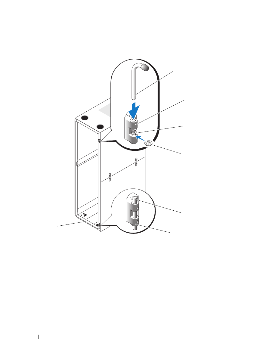
Abbildung 1-7. Oberes und unteres Scharnier umdrehen
1
2
3
4
5
7
6
1 Scharnierstift 2 Oberes Scharniergehäuse
3 Feder 4 Halteclip
5 Scharnierleiste 6 Unteres Scharniergehäuse
7 Rackvorderseite
90 Installationsanleitung
Page 93

g
Suchen Sie die oberen Bolzenlöcher auf der rechten Rackseite.
Befestigen Sie darin das Scharniergehäuse mit den Inbusbolzen.
h
Setzen Sie die Feder zwischen dem oberen und dem unteren
Scharnierstiftloch des Scharniergehäuses ein.
i
Lassen Sie den Scharnierstift in das Scharniergehäuse gleiten.
j
Fügen Sie den Halteclip unterhalb der Feder in das Scharnier ein.
4
Drehen Sie das untere Scharniergehäuse um.
a
Entfernen Sie die Inbusbolzen, mit deren Hilfe das Scharniergehäuse
am Rack befestigt ist. Bewahren Sie die Bolzen gut auf.
b
Drehen Sie das Scharniergehäuse um 180 Grad, so dass die
Scharnierleisten sich auf der anderen Seite des Scharniergehäuses
befinden (siehe Abbildung 1-7).
c
Suchen Sie die unteren Bolzenlöcher auf der rechten Rackseite.
Befestigen Sie darin das Scharniergehäuse mit den Inbusbolzen.
5
Drehen Sie die vordere Tür um 180 Grad, so dass deren Scharnierstiftgehäuse sich auf der rechten Seite befinden (siehe Abbildung 1-8).
Installationsanleitung 91
Page 94

Abbildung 1-8. Vordere Tür umdrehen
6
Hängen Sie die vordere Tür wieder ein, indem Sie die unter „Entfernen
der vorderen Tür“ auf Seite 80 aufgeführten Schritte in umgekehrter
Reihenfolge ausführen.
7
Drehen Sie den Verriegelungshebel um.
a
Entfernen Sie die beiden Kreuzschlitzschrauben, mit denen
der Verriegelungshebel am vertikalen Rahmenteil befestigt ist.
b
Entfernen Sie den Verriegelungshebel und drehen Sie ihn um
180 Grad.
c
Bringen Sie den Verriegelungshebel wieder am vertikalen Rahmenteil
des anderen Racks an. Richten Sie dabei die Löcher der Verriegelung
nach den Löchern am Rahmen aus und bringen Sie die zwei
Kreuzschlitzschrauben wieder an. Siehe Abbildung 1-9.
92 Installationsanleitung
Page 95

Abbildung 1-9. Verriegelungshebel an der vorderen Tür umkehren
1
1 Verriegelungshebel 2 Schrauben
8
Drehen Sie die auf der vorderen Tür angebrachte Plakette um.
a
Öffnen Sie die vordere Tür.
b
Führen Sie von der Innenseite der Tür aus einen Schlitzschraubendreher in die Verriegelungskerbe der Plakette ein (siehe Abbildung 1-10).
Installationsanleitung 93
2
Page 96

Abbildung 1-10. Plakette auf der vorderen Tür umdrehen
1
5
3
4
2
1 Verriegelungskerbe der Plakette 2 Plakette auf der vorderen Tür
3 Mittlere Laschen (2) 4 Halteklammern der Plakette (2)
5 Haken an der Plakette (2)
c
Drücken Sie den Schraubendreher so weit wie möglich in die Kerbe
und drehen Sie ihn gegen den Uhrzeigersinn.
d
Hebeln Sie die Plakette ab und entfernen Sie sie von der Tür.
e
Drehen Sie die Plakette um 180 Grad, damit sie nach dem Wiedereinbau korrekt gelesen werden kann.
94 Installationsanleitung
Page 97

f
Machen Sie den sechsten horizontalen Riegel von der Oberseite
der Tür aus ausfindig und schieben Sie die Haken der Plakette
darüber. Richten Sie dabei die mittleren Laschen der Plakette am
vertikalen Riegel der Tür aus.
g
Drücken Sie die Halteklammern der Plakette nach oben,
bis sie geschlossen sind und die Plakette gesichert ist.
Einstellen der höhenverstellbaren Rackfüße
WARNUNG: Lesen Sie die folgenden Anweisungen komplett durch, bevor Sie mit
dem Anpassen der höhenverstellbaren Füße beginnen.
Das Rack enthält vier höhenverstellbare Füße, die an den Ecken des Racks
befestigt werden. Mit den Füßen können Sie das Rack waagerecht ausrichten,
wenn es auf einem leicht unebenen Untergrund steht. Bevor Sie die Systeme
im Rack installieren, montieren Sie die Füße und passen Sie sie an den
Untergrund an. Befolgen Sie beim Ausrichten des Racks diese Richtlinien.
WARNUNG: Sorgen Sie beim Anpassen der Füße dafür, dass die Rollen an den
vier Ecken des Racks nicht mehr als 9,5 mm vom Boden abgehoben sind. Falls
beim Anpassen der höhenverstellbaren Füße mehr als 9,5 mm Zwischenraum
zwischen dem Boden und den Rollen entsteht, fahren Sie langsam die Füße ein
und stellen Sie das Rack an einen anderen Stellplatz, an dem die
höhenverstellbaren Füße nur wenig angepasst werden müssen.
WARNUNG: Verstellen Sie die Füße, bis jeder Fuß fest auf dem Boden aufliegt.
Nur bei festem Bodenkontakt können die einzelnen Füße das Gewicht des Racks
tragen und ein Wackeln des Racks wird verhindert. Wenn nicht alle höhenverstellbaren Füße festen Bodenkontakt haben, könnte das Rack aus dem
Gleichgewicht geraten und umkippen.
WARNUNG: Versuchen Sie nicht, das Rack mit ausgefahrenen Füßen zu
verschieben. Fahren Sie grundsätzlich zuerst die Füße ein, bevor Sie das Rack
bewegen. Bei ausgefahrenen Füßen könnte das Rack umkippen, wenn Sie es
verschieben wollen.
WARNUNG: Vor dem Installieren der Systeme sollten Sie grundsätzlich das Rack
ausrichten und die Stabilisatoren befestigen. Ein voll beladenes Rack könnte
umkippen, wenn es auf einem unebenen Untergrund steht und das Gewicht des
Rack nicht auf den höhenverstellbaren Füßen und Stabilisatoren lastet.
ANMERKUNG: Ist das Rack nicht korrekt ausgerichtet, können die Stabilisatoren
eventuell nicht angebracht werden. Ohne Stabilisatoren kann das Rack jedoch
umkippen.
Installationsanleitung 95
Page 98

1
Senken Sie mit einem Schraubendreher den Fuß, bis er auf dem Boden
aufliegt.
2
Wenn Sie den Fuß noch weiter herausfahren möchten, drehen Sie die
Sechskantmutter mit einem 12-mm-Schraubenschlüssel im Uhrzeigersinn
fest (siehe Abbildung 1-11).
3
Wiederholen Sie Schritt 1 und 2 für die übrigen höhenverstellbaren Füße.
4
Überprüfen Sie, ob das Rack eben und stabil steht.
96 Installationsanleitung
Page 99

Abbildung 1-11. Höhenverstellbare Füße anpassen
1 Schaft des höhenverstellbaren Fußes 2 Sechskantmutter
3 Nivellierungsblock
1
2
3
Installationsanleitung 97
Page 100

Anbringen der Stabilisatoren
WARNUNG: Werden Systeme in einem Rack installiert, an dem die vorderen und
seitlichen Stabilisatoren fehlen, kann das Rack umkippen, was unter Umständen
schwere Verletzungen nach sich ziehen kann. Befestigen Sie daher immer zuerst
die Stabilisatoren, bevor Sie Komponenten im Rack installieren.
Befestigen Sie die Stabilisatoren in folgender Reihenfolge am Rack:
• Bringen Sie bei einem freistehenden Rack auf der Vorderseite und an den
Seiten Stabilisatoren an.
• Befestigen Sie in einer Rackreihe an jedem Rack einen vorderen
Stabilisator. Bringen Sie außerdem an den beiden Racks am Anfang und
am Ende der Reihe einen linken bzw. rechten Stabilisator an.
Installieren der vorderen Stabilisatoren
1
Öffnen Sie die vordere Tür.
2
Fassen Sie in das Rack und ziehen Sie alle Stabilisatoren fest nach oben,
um sie vom Rahmen zu lösen.
3
Entfernen Sie die Kunststoffbefestigungen, die an den Stabilisatoren
angebracht sind.
4
Legen Sie die vorderen Stabilisatoren jeweils vor den Rackrahmensockel
und richten Sie die Fußlöcher nach den entsprechenden Rahmenlöchern
aus.
5
Befestigen Sie den Stabilisator mit den mitgelieferten Schrauben,
Unterlegscheiben und Käfigmuttern am Rack, wie in Abbildung 1-12
dargestellt.
98 Installationsanleitung
 Loading...