

Page 1

Dell™ PowerConnect™ 3324/3348
User’s Guide
Model PowerConnect 3324/3348
www.dell.com | support.dell.com
Page 2

Notes, Notices, and Cautions
NOTE: Notes indicate important information that helps you make better use of your device.
NOTICE: Notices indicate either potential damage to hardware or loss of data and tells you
how to avoid the problem.
CAUTION: Caution indicates a potential for property damage, personal injury, or
death.
Information in this document is subject to change without notice.
© 2003 Dell Inc. All rights reserved.
Reproduction in any manner whatsoever without the written permission of Dell Inc. is strictly forbidden.
Trademarks used in this text: Dell, the DELL logo, PowerConnect, Dell O penManage, PowerEdge, Inspiron, Dell
Precision, Dimension, OptiPlex, Axim, PowerVault, PowerApp, DellNet, and Latitude are trademarks of Dell Inc.;
Microsoft and Windows are registered trademarks of Microsoft Corporation.
Other trademarks and trade names may be used in this document to refer to either the entities claiming the marks and
names or their products. Dell Inc. disclaims any proprietary interest in trademarks and trade names other than its own.
November 2003 Rev. A01
Page 3

Contents
1 Overview
System Description . . . . . . . . . . . . . . . . . . . . . . . . . 12
PowerConnect 3324/3348 Stacking Overview
Stack Members and Unit ID
Configuration Handling
Rearranging Stacks
Replacing Stack Members
PowerConnect User Guide Overview
Installing the PowerConnect 3324/3348 Switch
Using the Dell OpenManage Switch Administrator
PowerConnect 3324/3348 CLI Documentation
2 Hardware Description
PowerConnect 3324/3348 Description . . . . . . . . . . . . . . . 20
PowerConnect 3324/3348 Dimensions
PowerConnect 3324/3348 Rear Panel
PowerConnect 3324/3348 Components
Ports Description
Ethernet Port Description
Console Port Description
. . . . . . . . . . . . . . . . . . . . . . . . . . 24
. . . . . . . . . . . 12
. . . . . . . . . . . . . . . . . . . 13
. . . . . . . . . . . . . . . . . . . . . 14
. . . . . . . . . . . . . . . . . . . . . . . 15
. . . . . . . . . . . . . . . . . . . . 15
. . . . . . . . . . . . . . . . 17
. . . . . . . . . 17
. . . . . . . . 17
. . . . . . . . . . 18
. . . . . . . . . . . . . 20
. . . . . . . . . . . . . . 20
. . . . . . . . . . . . . 20
. . . . . . . . . . . . . . . . . . . . 24
. . . . . . . . . . . . . . . . . . . . 24
LED Definitions
Port LEDs
System LEDs
Stacking LEDs
. . . . . . . . . . . . . . . . . . . . . . . . . . . 24
. . . . . . . . . . . . . . . . . . . . . . . . . . . 26
. . . . . . . . . . . . . . . . . . . . . . . . . . 26
. . . . . . . . . . . . . . . . . . . . . . . . . 28
Contents 3
Page 4

3 Installing the PowerConnect 3324/3348 Switch
Installation Precautions . . . . . . . . . . . . . . . . . . . . . . 30
Site Requirements
Unpacking and Installation
Package Contents
Unpacking
Device Rack Installation
Installing the Switch without a Rack
Stacking PowerConnect 3324/3348
Connecting Stacking Cables
. . . . . . . . . . . . . . . . . . . . . . . . . 30
. . . . . . . . . . . . . . . . . . . . 31
. . . . . . . . . . . . . . . . . . . . . . . 31
. . . . . . . . . . . . . . . . . . . . . . . . . . . 31
. . . . . . . . . . . . . . . . . . . . 32
. . . . . . . . . . . . . . 32
. . . . . . . . . . . . . . 33
. . . . . . . . . . . . . . . . . . 33
Connecting the PowerConnect 3324/3348 to a
Power Supply
Cable, Port, and Pinout Information
Port Connections
Cable Connections
. . . . . . . . . . . . . . . . . . . . . . . . . 34
. . . . . . . . . . . . . . . 35
. . . . . . . . . . . . . . . . . . . . . . . . 36
. . . . . . . . . . . . . . . . . . . . . . . 38
4 Configuring the PowerConnect 3324/3348 Switch
Configuration Overview . . . . . . . . . . . . . . . . . . . . . . 42
General Configuration Information
Auto-Negotiation
. . . . . . . . . . . . . . . . . . . . . . . 43
Switching Port Default Settings
Baud Rate
. . . . . . . . . . . . . . . . . . . . . . . . . . . 45
. . . . . . . . . . . . . . . . 43
. . . . . . . . . . . . . . . . 44
4 Contents
Terminal Connection Configuration
Other Configuration Requirements
Booting the Device
. . . . . . . . . . . . . . . . . . . . . . . . 46
Device Configuration Introduction
Initial Configuration
. . . . . . . . . . . . . . . . . . . . . . . . 49
Static IP Address and Subnet Mask
Default Gateway
. . . . . . . . . . . . . . . . . . . . . . . . 51
. . . . . . . . . . . . . . . . 45
. . . . . . . . . . . . . . . . 46
. . . . . . . . . . . . . . . . 48
. . . . . . . . . . . . . . 49
Page 5

User Name, Password, and Privilege Level . . . . . . . . . . . 51
SNMP Community Strings
. . . . . . . . . . . . . . . . . . . 51
Advanced Configuration
. . . . . . . . . . . . . . . . . . . . . . 53
Retrieving an IP address from a DHCP Server
Receiving an IP address from a BOOTP Server
Security Management and Password Configuration
Configuring Security Passwords
Sample Configuration Process
Device Setup Requirements
Initial Connection
Device Default Settings
. . . . . . . . . . . . . . . . . . . . . . . . 60
. . . . . . . . . . . . . . . . . . . . . 64
Remote Management Access
. . . . . . . . . . . . . . . . . 57
. . . . . . . . . . . . . . . . . . . 60
. . . . . . . . . . . . . . . . . . . 60
. . . . . . . . . . . . . . . . . . 65
Start Running the Management Station
Telnet access
Web Access (HTTP server)
Configuring Stacking
Stacking Introduction
Stacking Requirements
Configuring a Stack
Expanding the Stack
Rebooting the Device
. . . . . . . . . . . . . . . . . . . . . . . . . . 70
. . . . . . . . . . . . . . . . . . . 72
. . . . . . . . . . . . . . . . . . . . . . . . 75
. . . . . . . . . . . . . . . . . . . . . . 75
. . . . . . . . . . . . . . . . . . . . . 75
. . . . . . . . . . . . . . . . . . . . . . . 75
. . . . . . . . . . . . . . . . . . . . . . 76
. . . . . . . . . . . . . . . . . . . . . . . . 76
. . . . . . . . . 54
. . . . . . . . . 55
. . . . . . . 56
. . . . . . . . . . . . . 68
Startup Menu Functions
Downloading the Software
Erasing the FLASH File
Erasing FLASH Sectors
Password Recovery
Running Diagnostics
. . . . . . . . . . . . . . . . . . . . . . 77
. . . . . . . . . . . . . . . . . . . 77
. . . . . . . . . . . . . . . . . . . . 78
. . . . . . . . . . . . . . . . . . . . 79
. . . . . . . . . . . . . . . . . . . . . . . 80
. . . . . . . . . . . . . . . . . . . . . . . 80
Downloading the Software to Stacking Units
Downloading the Software Sequentially Using the CLI
Downloading the Software Individually Using the CLI
Downloading the Software Via the
PowerConnect 3324/3348 Dell OpenManage Switch
Administrator
. . . . . . . . . . . . . . . . . . . . . . . . . . 84
. . . . . . . . . . . 80
. . . . . 81
. . . . . . 82
Contents 5
Page 6

Defining SNMP Settings . . . . . . . . . . . . . . . . . . . . . 85
Connecting Devices
5 Getting Started
Starting the Switch Administrator . . . . . . . . . . . . . . . . 88
Understanding the Interface
Tree View
Device View
Device Representation
Using the Switch Administrator Buttons
Information Buttons
About PageDevice Management Buttons
Using the CLI
Command Mode
User EXEC Mode
Privileged EXEC Mode
Global Configuration Mode
Interface Configuration Mode
. . . . . . . . . . . . . . . . . . . . . . . . . . . 89
. . . . . . . . . . . . . . . . . . . . . . . . . . . 97
. . . . . . . . . . . . . . . . . . . . . . . . 86
. . . . . . . . . . . . . . . . . . . 88
. . . . . . . . . . . . . . . . . . . . . . . . . . 90
. . . . . . . . . . . . . . . . . . . . . 90
. . . . . . . . . . . . . 92
. . . . . . . . . . . . . . . . . . . . . . 93
. . . . . . . . . . . . 95
. . . . . . . . . . . . . . . . . . . . . . . . 97
. . . . . . . . . . . . . . . . . . . . . . . 97
. . . . . . . . . . . . . . . . . . . . 98
. . . . . . . . . . . . . . . . . . 99
. . . . . . . . . . . . . . . . . 99
Starting the CLI
Console Connection
Telnet Connection
. . . . . . . . . . . . . . . . . . . . . . . . . . 100
. . . . . . . . . . . . . . . . . . . . . . 100
. . . . . . . . . . . . . . . . . . . . . . . 101
6 Configuring System Information
Defining General Device Information . . . . . . . . . . . . . . . 104
Viewing the Asset Page
Viewing System Health Information
Viewing the Versions Page
Resetting the Device
6 Contents
. . . . . . . . . . . . . . . . . . . . . . 112
. . . . . . . . . . . . . . . . . . . . 105
. . . . . . . . . . . . . . 109
. . . . . . . . . . . . . . . . . . . 110
Page 7

Managing Logs . . . . . . . . . . . . . . . . . . . . . . . . . . 113
Defining Global Log Parameters
Displaying RAM Log Table
Displaying the Log File Table
Displaying the Log File Table Using the CLI Commands
Viewing the Remote Log Server Settings Page
. . . . . . . . . . . . . . . . 114
. . . . . . . . . . . . . . . . . . 118
. . . . . . . . . . . . . . . . . 121
. . . . 121
. . . . . . . . . 123
Defining Device IP Addresses
Defining Default Gateways
Defining IP Interfaces
. . . . . . . . . . . . . . . . . . 126
. . . . . . . . . . . . . . . . . . 127
. . . . . . . . . . . . . . . . . . . . . 130
Defining DHCP IP Interfaces
Configuring ARP
Managing Device Security
Defining Access Profiles
. . . . . . . . . . . . . . . . . . . . . . . 136
. . . . . . . . . . . . . . . . . . . . 139
. . . . . . . . . . . . . . . . . . . . 141
Defining Authentication Profiles
Assigning Authentication Profiles
Defining the Local User Databases
Defining Line Passwords
Defining Enable Password
. . . . . . . . . . . . . . . . . . . 160
. . . . . . . . . . . . . . . . . . . 161
Configuring RADIUS Global Parameters
Defining SNMP Parameters
Defining Communities
Defining Traps
Managing Files
. . . . . . . . . . . . . . . . . . . . . . . . 171
. . . . . . . . . . . . . . . . . . . . . . . . . . 175
File Management Overview
Downloading Files
Uploading Files
. . . . . . . . . . . . . . . . . . . . . . . . 180
Resetting the Active Image
Copying and Deleting Files
. . . . . . . . . . . . . . . . . . . 168
. . . . . . . . . . . . . . . . . . . . . 169
. . . . . . . . . . . . . . . . . . 176
. . . . . . . . . . . . . . . . . . . . . . . 177
. . . . . . . . . . . . . . . . . . 182
. . . . . . . . . . . . . . . . . . 183
. . . . . . . . . . . . . . . . . 133
. . . . . . . . . . . . . . . . 148
. . . . . . . . . . . . . . . 152
. . . . . . . . . . . . . . 157
. . . . . . . . . . . 163
Defining Advanced Settings . . . . . . . . . . . . . . . . . . . 186
Configuring General Device Tuning Parameters
. . . . . . . . 187
Contents 7
Page 8

7 Configuring Switch Information
Configuring Network Security . . . . . . . . . . . . . . . . . . 190
Network Security Overview
Configuring Port Security
Defining IP-Based ACLs
Defining MAC-Based ACLs
Binding ACLs
. . . . . . . . . . . . . . . . . . . . . . . . . 205
. . . . . . . . . . . . . . . . . . 191
. . . . . . . . . . . . . . . . . . . 193
. . . . . . . . . . . . . . . . . . . . 196
. . . . . . . . . . . . . . . . . . 200
Configuring Ports
Defining Port Parameters
Defining LAG Parameters
Enabling Storm Control
Defining Port Mirroring Sessions
Configuring Address Tables
Defining Static Addresses
Viewing Dynamic Addresses
Configuring GARP
Defining GARP Timers
. . . . . . . . . . . . . . . . . . . . . . . . . 207
. . . . . . . . . . . . . . . . . . . 208
. . . . . . . . . . . . . . . . . . . 216
. . . . . . . . . . . . . . . . . . . . 222
. . . . . . . . . . . . . . . . 225
. . . . . . . . . . . . . . . . . . . . 229
. . . . . . . . . . . . . . . . . . . 230
. . . . . . . . . . . . . . . . . . 233
. . . . . . . . . . . . . . . . . . . . . . . . . 235
. . . . . . . . . . . . . . . . . . . . . 236
Configuring the Spanning Tree Protocol
Defining STP Global Settings
Defining STP Port Settings
Defining STP LAG Settings
Configuring Rapid Spanning Tree
Configuring VLANs
. . . . . . . . . . . . . . . . . . . . . . . . 254
Defining VLAN Members
Defining VLAN Ports Settings
Defining VLAN LAG Settings
Configuring GVRP
. . . . . . . . . . . . . . . . . . . . . . . 267
. . . . . . . . . . . . . . . . . 240
. . . . . . . . . . . . . . . . . . 244
. . . . . . . . . . . . . . . . . . 248
. . . . . . . . . . . . . . . . 251
. . . . . . . . . . . . . . . . . . . 256
. . . . . . . . . . . . . . . . . 261
. . . . . . . . . . . . . . . . . 264
. . . . . . . . . . . . . 239
8 Contents
Aggregating Ports
Defining LACP Parameters
Defining LAG Membership
. . . . . . . . . . . . . . . . . . . . . . . . . 272
. . . . . . . . . . . . . . . . . . 274
. . . . . . . . . . . . . . . . . . . 279
Page 9

Multicast Forwarding Support . . . . . . . . . . . . . . . . . . 280
Defining IGMP Snooping Settings
Adding Bridge Multicast Group Members
Assigning Multicast Forward All Parameters
Enabling IGMP Snooping
8 Viewing Statistics
Viewing Tables . . . . . . . . . . . . . . . . . . . . . . . . . . 294
Viewing Utilization Summary
Viewing Counter Summary
Viewing Interface Statistics
Viewing Interface Statistics Using the CLI Commands
Viewing Etherlike Statistics
Viewing GVRP Statistics
Viewing GVRP Statistics Using the CLI Commands
. . . . . . . . . . . . . . . 281
. . . . . . . . . . . 284
. . . . . . . . . 287
. . . . . . . . . . . . . . . . . . . 289
. . . . . . . . . . . . . . . . . 295
. . . . . . . . . . . . . . . . . . 297
. . . . . . . . . . . . . . . . . . 298
. . . . 300
. . . . . . . . . . . . . . . . . . 301
. . . . . . . . . . . . . . . . . . . 304
. . . . . . 305
Viewing RMON Information
Viewing RMON Statistics
. . . . . . . . . . . . . . . . . . . 307
. . . . . . . . . . . . . . . . . . . 307
Viewing History Control Statistics
Viewing The RMON History Table
Defining Device Events
Viewing the Events Log
Defining Device Alarms
Viewing Charts
Viewing Port Statistics
Viewing LAG Statistics
. . . . . . . . . . . . . . . . . . . . . . . . . . 326
. . . . . . . . . . . . . . . . . . . . 316
. . . . . . . . . . . . . . . . . . . . 320
. . . . . . . . . . . . . . . . . . . . 321
. . . . . . . . . . . . . . . . . . . . 327
. . . . . . . . . . . . . . . . . . . . 331
9 Configuring Quality of Service
Quality of Service (QoS) Overview . . . . . . . . . . . . . . . . 336
. . . . . . . . . . . . . . 310
. . . . . . . . . . . . . . . 313
Contents 9
Page 10

Defining QoS Global Parameters . . . . . . . . . . . . . . . . . 339
Configuring Global QoS Settings
Defining QoS Interface Settings
Defining Queue Settings
. . . . . . . . . . . . . . . . . . . . 343
. . . . . . . . . . . . . . . . 340
. . . . . . . . . . . . . . . . 342
Mapping to Queues
Mapping CoS Values to Queues
Mapping DSCP Values to Queues
Mapping TCP Port Values to Queues
Mapping UDP Port Values to Queues
10 Getting Help
Technical Assistance . . . . . . . . . . . . . . . . . . . . . . . . 358
Online Services
AutoTech Service
Automated Order-Status Service
Technical Support Service
Dell Enterprise Training and Certification
Problems With Your Order
Product Information
Returning Items for Warranty Repair or Credit . . . . . . . . . . 360
Before You Call
. . . . . . . . . . . . . . . . . . . . . . . . 346
. . . . . . . . . . . . . . . . 346
. . . . . . . . . . . . . . . . 348
. . . . . . . . . . . . . . 350
. . . . . . . . . . . . . . 353
. . . . . . . . . . . . . . . . . . . . . . . . 358
. . . . . . . . . . . . . . . . . . . . . . . 359
. . . . . . . . . . . . . . . . 359
. . . . . . . . . . . . . . . . . . . 360
. . . . . . . . . . . . 360
. . . . . . . . . . . . . . . . . . . . . 360
. . . . . . . . . . . . . . . . . . . . . . . . 360
. . . . . . . . . . . . . . . . . . . . . . . . . . 361
10 Contents
Contacting Dell
. . . . . . . . . . . . . . . . . . . . . . . . . . 361
Page 11

SECTION 1
Overview
System Description
PowerConnect 3324/3348 Stacking Overview
PowerConnect User Guide Overview
PowerConnect 3324/3348 CLI Documentation
Page 12
System Description
The Dell™ PowerConnect™ 3324 and 3348 devices are standalone and stackable advanced
Layer 2 switches. PowerConnect 3324 and PowerConnect 3348 also function as stand-alone
Layer 2 switching systems. PowerConnect 3324/3348 devices are managed either using InBand Management (via the network station remotely) or via the console.
www.dell.com | support.dell.com
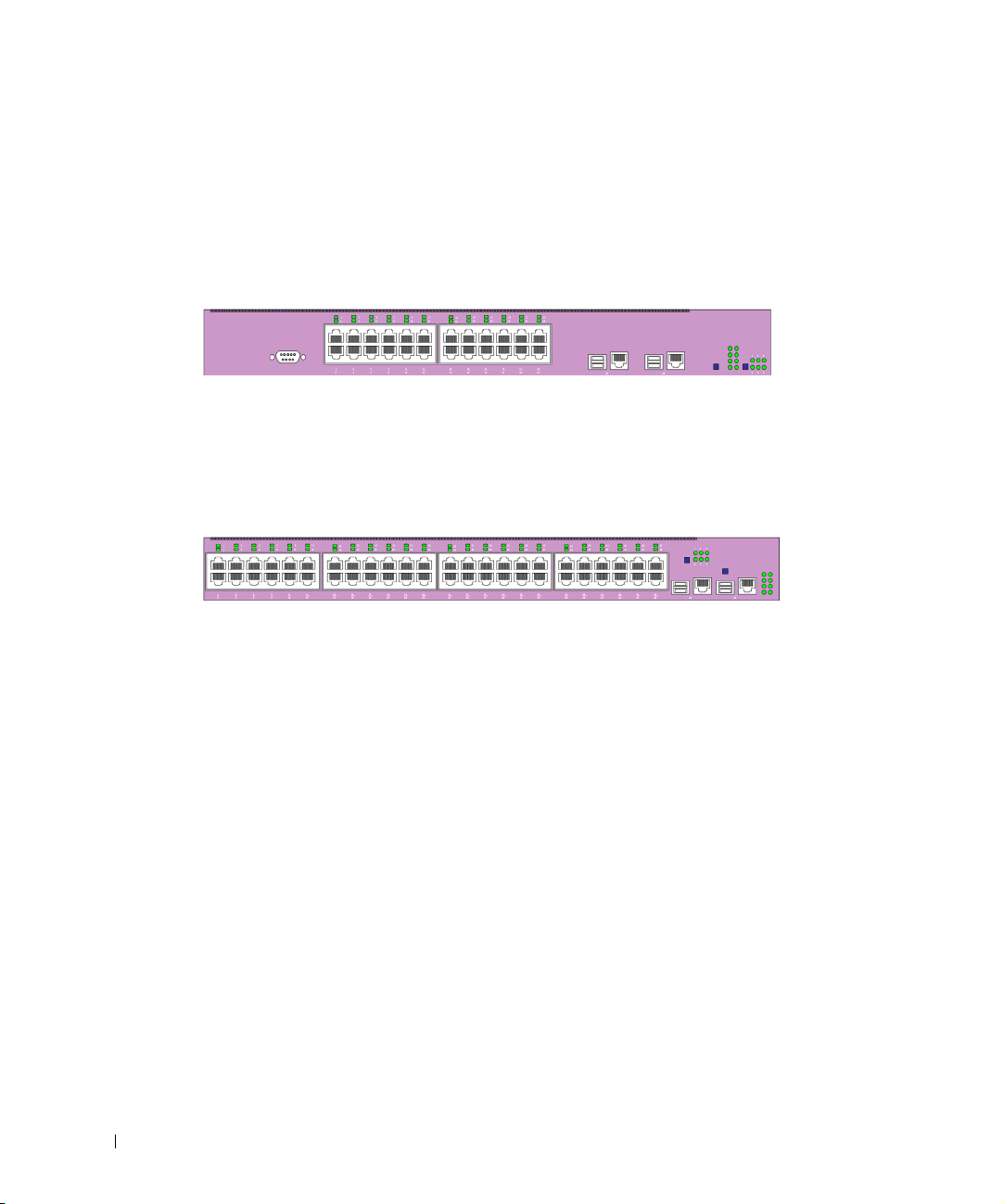
PowerConnect 3324
When operating as a stack member, each PowerConnect 3324 unit provides 24 10
BaseT/100BaseTX Fast Ethernet ports, one Gigabit Ethernet Combo port (10/100/1000
BaseT or Mini GBIC connector), and one Giga Ethernet stacking port.
PowerConnect 3348
When operating as a stack member, each PowerConnect 3348 unit provides 48 10
BaseT/100BaseTX Fast Ethernet ports, one Gigabit Ethernet Combo port (10/100/1000
BaseT or Mini GBIC connector), and one Giga Ethernet stacking port.
When operating as a stand-alone unit, the PowerConnect 3324/3348 stacking ports can be
used as Giga Ethernet ports.
PowerConnect 3324/3348 Stacking Overview
PowerConnect 3324/3348 stacking provides multiple device management through a single
point as if all stack members are a single unit. All members are accessed through a single IP
address for SNMP management and a console/telnet session through which the entire stack
is managed.
12 Overview
PowerConnect 3324/3348 supports stacking up to six units per stack or scale up to 192 FE
and six Gigabit Ethernet ports. PowerConnect 3324/3348 can also operate as standalone
units.
Page 13

During the stacking setup, one device is selected by the network administrator as the stack
master, while all other devices are selected as stack members and assigned a unique Unit ID.
PowerConnect 3324/3348 stacks provide across-the-stack Layer 2 functionality including:
• Switching
• Trunking
• Port Mirroring
•VLANs
For example, VLANs can be configured from ports belonging to different stack members, or
configure port mirroring from a second stack member to a third stack member. Applications
running in a stacking configuration are centralized. For example, the Spanning Tree
Protocol for the entire stack runs on the master unit. Device software is downloaded
separately for each stack member.
PowerConnect 3324/3348 stacking architecture provides dynamic learning for the stacking
topology, while detecting and reconfiguring the ports with minimal operational impact in
the event of:
• Unit Failure
• Inter-unit Link Loss
• Unit Insertion
• Removal of a Stacking Unit
Stack Members and Unit ID
The stacking operation mode is determined during the Boot process.
PowerConnect 3324/3348 units are shipped with a default Unit ID of one. The Unit ID is
essential to the stacking configuration. If a stack member reboots without a stacking
module, the device operates as a stand-alone until the device is reset. If a PowerConnect
3324/3348 unit is operating as a stand-alone unit, all stacking LEDs are off. The Unit ID is
not erased and remains valid if the unit is reconnected to a stack.
NOTE: The stacking module must be inserted into port G2 for the stack to operate. If the
stacking module is inserted in port G1, a warning message is displayed on the console.
Overview 13
Page 14

When the master unit boots or when inserting or removing a stack member, the master unit
initiates a stacking discover process. If two members are discovered with the same Unit ID,
or a master unit is not found, the entire stack cannot function. The stacking LED remains
red.
Configuration Handling
In a PowerConnect 3324/3348 operative stack, the stack master is responsible for the stack
configuration. Each stack member does not have a separate configuration file. Each port in
the stack has a specific Unit ID/port type and port number, which is part of both the
configuration commands and the configuration files. Configuration files are managed only
from the PowerConnect 3324/3348 stack master, including:
www.dell.com | support.dell.com
• Saving to the FLASH.
• Uploading Configuration files to an external TFTP Server.
• Downloading Configuration files from an external TFTP Server.
NOTE: Stack configuration for all configured ports is saved, even if the stack is reset and/or the
ports are no longer present.
Configuration files are changed only through explicit user configuration. In addition,
Configuration files are not automatically modified when:
• Units are added.
14 Overview
• Units are removed.
• Units are reassigned Unit IDs.
• Units toggle between stacking mode and stand-alone mode.
Each time the system reboots, the stored configuration is written in the Startup
Configuration file.
If a PowerConnect 3324/3348 stack member is removed from the stack, and then replaced
with the same Unit ID, the stack member is configured with the original device
configuration.
Only ports that are physically present are displayed in the Dell OpenManage™ Switch
Administrator and can be configured through the web management system. Non-present
ports are configured through the CLI or SNMP interfaces.
Page 15

Rearranging Stacks
The stacking order can be changed by either removing a stack member or by rearranging the
stacking cables. The order in which stack members are arranged is established not by the
physical order of the stack members but by the Unit ID assignment. The stack
configuration is stored in stack master after the stack order is changed, and the stack is
reset.
If the PowerConnect 3324/3348 unit is removed or replaced in a stack, the stack recovers
from the disconnection as follows:
• If the stack is disconnected for more than two minutes, the entire stack no longer
forwards network traffic. Every stack member reboots and waits until the stack is
reconnected. If the unit is not replaced, the master unit constantly polls the stack.
• If the stack is reconnected in under two minutes, all units remain stacked and regain
their connection to other units within five seconds. A new stack member is connected
to the master unit but initialized according to the master unit’s configuration. If a
configuration is not stored, the device is configured with the default configuration.
Replacing Stack Members
If a stack member is replaced with a new device, the requested device ID is selected. In
addition, the previous device configuration is applied to the inserted stack member. If the
new inserted device has either more or fewer ports than the previous device, the relevant
port configuration is applied to the new stack member. For example:
• If a PowerConnect 3324 replaces a PowerConnect 3324, the new 24 10/100 BaseT
ports receive the previous 24 10/100 BaseT port configuration. Ports G1 and G2 receive
the previous device’s G1 and G2 port configuration.
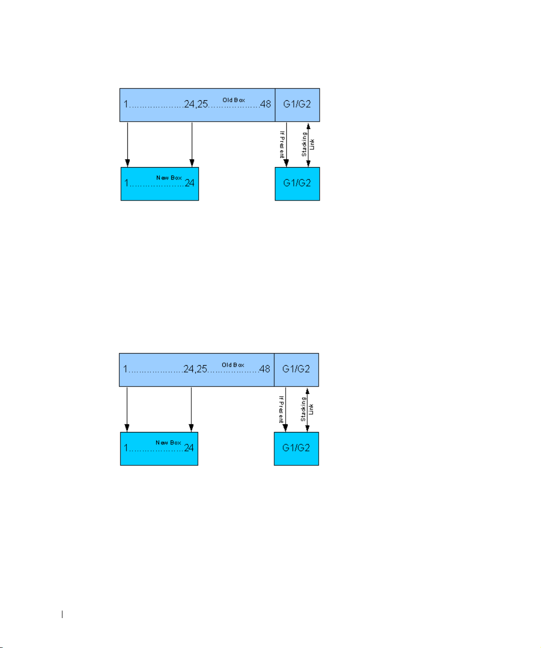
• If a PowerConnect 3324 replaces PowerConnect 3348, then ports 1-24 10/100 BaseT
receive the previous device’s configuration for ports 1-24. Ports G1 and G2 receive the
previous device’s G1 and G2 port configuration.
Overview 15
Page 16
www.dell.com | support.dell.com
PowerConnect 3324 Replaces PowerConnect 3348
• If a PowerConnect 3348 replaces PowerConnect 3348, the new 48 10/100 BaseT ports
receive the previous 48 10/100 BaseT port configuration. Ports G1 and G2 receive the
previous device’s G1 and G2 port configuration.
• If a PowerConnect 3348 replaces PowerConnect 3324, then ports 1-24 10/100 BaseT
receive the previous device’s configuration for ports 1-24.
• Ports 25-48 receive the factory default port configuration. Ports G1 and G2 receive the
previous device’s G1 and G2 port configuration.
PowerConnect 3348 Replace PowerConnect 3324
16 Overview
Page 17

PowerConnect User Guide Overview
The PowerConnect User Guide is divided into two parts:
• About Installing the PowerConnect 3324/3348 Switch
• Using the Dell OpenManage Switch Administrator
Installing the PowerConnect 3324/3348 Switch
This section contains the following sections about unpacking, installing, and configuring
the PowerConnect 3324/3348:
• Hardware Description—Contains information about the PowerConnect 3324/3348
hardware, including a description of the ports and LED types.
• Installing the PowerConnect 3324/3348 Switch—Contains instructions about
installing PowerConnect 3324/3348 in either a rack or on a flat surface. In addition,
this section contains installation precautions, and a description of the connectors and
cables.
• Configuring the PowerConnect 3324/3348 Switch—Contains instructions about
initial device configuration, including downloading device software, the device boot
screen, and optional configuration functions.
Using the Dell OpenManage Switch Administrator
This section contains the following information about configuring the device using the web
management system and Command Line Interface (CLI) device management system:
• Getting Started—Contains information about getting started with the web
management system interface, including an explanation of the management and
information icons, the Components List, and the Device and Tr e e Views.
• Configuring System Information—Contains information about configuring general
system information including defining system information, configuring a default IP
address, defining device security and SNMP communities, downloading the device
software, and defining advanced settings.
• Configuring Switch Information—Contains information about configuring port and
VLANs, defining both static and dynamic address tables, configuring GARP and
GVRP, defining Spanning Tree parameters, aggregating ports, and configuring
Multicast forwarding support.
• Viewing Statistics—Contains information about viewing table and chart statistics for
ports, GVRP, Etherlike, RMON, and interface statistics.
Overview 17
Page 18

• Configuring Quality of Service—Contains information about configuring device Class
of Service.
• Getting Help—Contains information about technical assistance, problems with your
order, returning items for repair or credit, and how to contact Dell.
PowerConnect 3324/3348 CLI Documentation
In addition to the PowerConnect 3324/3348 User Guide, Dell provides the PowerConnect
3324/3348 CLI Reference Guide. The PowerConnect 3324/3348 CLI Reference Guide
provides information about the CLI commands used to configure the PowerConnect
3324/3348.
www.dell.com | support.dell.com
18 Overview
Page 19

SECTION 2
Hardware Description
PowerConnect 3324/3348 Description
Ports Description
LED Definitions
Page 20
PowerConnect 3324/3348 Description
PowerConnect 3324/3348 Dimensions
This device has the following dimensions:
• Width—19”
• Height—1U
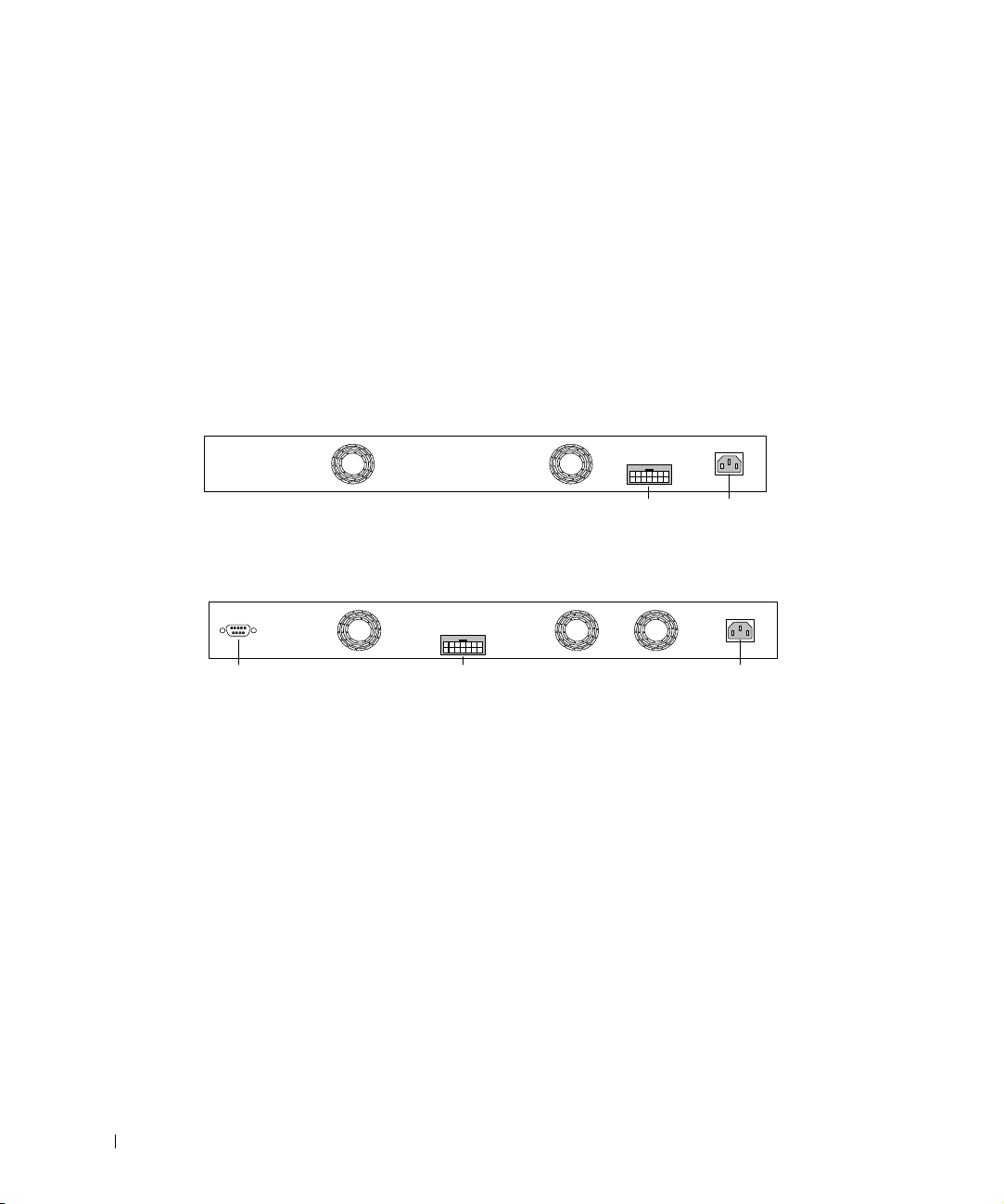
PowerConnect 3324/3348 Rear Panel
The rear panel of the Dell™ PowerConnect™ 3324/3348 is shown in the following figure:
www.dell.com | support.dell.com
RPS - DC
RPS Connector
Power
Connector
PowerConnect 3324 Rear Panel
RPS - DC
Power ConnectorRPS ConnectorConsole Port
PowerConnect 3348 Rear Panel
PowerConnect 3324/3348 Components
This section describes different PowerConnect 3324/3348 hardware components, and
includes the following topics:
• General Device Components
• Mode Button
• Stack ID Button
20 Hardware Description
Page 21
General Device Components
G1 G2
Stack ID Button
Stacking LEDs
The PowerConnect 3324/3348 includes the following hardware components:
• CPU—Based on Motorola’s MPC 8245.
• FLASH—Contains 8 MB of FLASH Memory.
• SDRAM—Contains 32 MB.
123
456
Stacking LEDs
1
43658710912
2
14365871091211141316151817201922212423
2
11
13
161518172019222124
14
PowerConnect 3324 Front Panel
Stack ID Button
G1 G2
1
43658710912
2
14365871091211141316151817201922212423
2
PowerConnect 3348 Front Panel
11
13
161518172019222124
14
23
25
282730293231343336
26
2528273029323134333635383740394241444346454847
26
123
456
23
35
37
403942414443464548
38
47
123
456
123
456
G1 G2
Hardware Description 21
Page 22

Mode Button
The Mode Button toggles between port activity and port duplex settings.
Stack ID Button
The PowerConnect 3324/3348 front panel contains a Stack ID button that permits network
administrators to manually select the Stack Master and stack members.
NOTE: The Stack Master and stack members must be selected within 15 seconds after booting
the device. If the Stack Master is not selected within 15 seconds, the device must be reset to
select the Unit IDs.
Once the Stack Master is selected, the remaining devices are defined as stack members.
www.dell.com | support.dell.com
Master units receive the Unit ID of 1. Stack members receive a separate Unit ID (2-6). For
example, if there are 4 units in a stack, the Master unit is 1, the second stack member is 2,
the third stack member is 3, and the fourth stack member is 4.
Stacking Modules and Connectors
PowerConnect 3324/3348 Stacking modules are connected to port G2. The Stack module is
a mini GBIC module with two stacking connectors: RX and TX. RX is the lower connection
point, and TX is the upper connection point. The module is connected to other stacking
units using a stacking cable connection. The top unit’s RX is connected to the lower unit’s
TX. This completes the Ring Topology. The Stacking Connections figure illustrates the
Ring Topology.
22 Hardware Description
Page 23

Master Unit
#1
Tx
Member Unit
#1
Rx
Tx
Member Unit
#2
Rx
Tx
Member Unit
#3
Rx
Tx
Rx
Stacking Connections
For more information about connecting Stacking cables, see "Connecting Stacking Cables".
Hardware Description 23
Page 24

Ports Description
Ethernet Port Description
The PowerConnect 3324 features 24 FE 10BaseT/100BaseTX UTP copper RJ45 ports per
unit and 2 combo ports. The PowerConnect 3348 features 48 FE 10BaseT/100BaseTX UTP
copper RJ45 ports per unit and 2 combo ports. Each combo port is a single logical port that
has the following two physical interfaces:
• 1000Base-T connectors.
• Mini-GBIC (SFP) connectors.
www.dell.com | support.dell.com
Only one of the two physical connections of a combo port may be used at any one time.
If auto-MDIX is enabled, PowerConnect 3324/3348 automatically detects and corrects the
difference between crossover and straight-through cables on all ports.
PowerConnect 3324/3348 supports half and full duplex mode 10/100 M bps speed for
copper ports.
Console Port Description
The console port interface supports synchronous data of eight data bits, one stop bit, and
no parity. All RS232 pins are supported (9 pins) for Modem support.
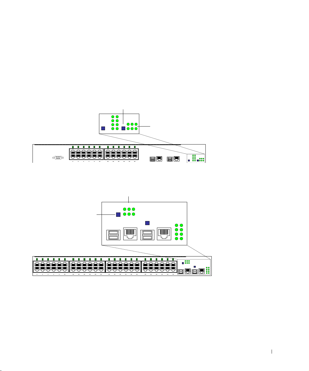
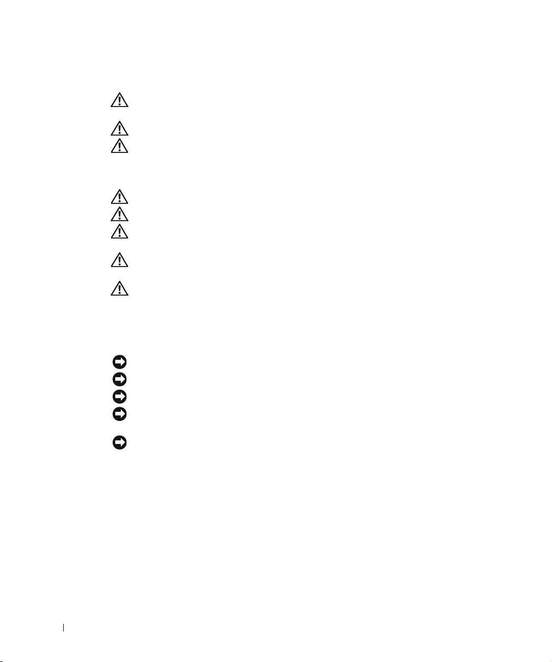
LED Definitions
The front panel LEDs in the following figures indicate the status of port links and modes,
power supply status, stacking status, and system diagnostics. The LED types are as follows:
• Port LEDs
• System LEDs
• Stacking LEDs
24 Hardware Description
Page 25
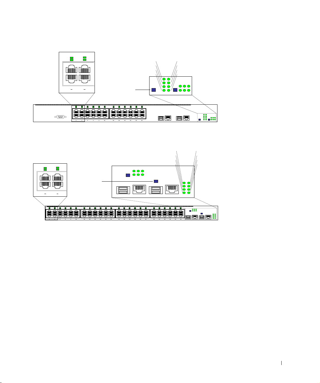
1
System LEDs
System LEDs
2
143
2
3
4
Button
Mode
Link/Act
Duplex
G1
G2
PWR
Diag
RPS
Stack
123
456
1
43658710912
2
14365871091211141316151817201922212423
2
11
Front Panel LEDs: 24 Ports
3
1
4
2
Mode
Button
143
2
1
43658710912
2
14365871091211141316151817201922212423
2
11
13
161518172019222124
14
23
Front Panel LEDs: 48 Ports
13
161518172019222124
14
23
G1 G2
Link/Act
Duplex
123
456
G1 G2
25
282730293231343336
26
2528273029323134333635383740394241444346454847
26
35
37
403942414443464548
38
G1
G2
47
PWR
Diag
RPS
Stack
123
456
49 50
123
456
Hardware Description 25
Page 26

Port LEDs
Each port has one corresponding LED located above the port. The LEDs show either link
activity or duplex mode, depending on the port LED display mode. For information about
setting the LED display mode, see "System LEDs".
Color Activity Definition
Green Static Port link up.
Green Flashing Port link up with activity.
www.dell.com | support.dell.com
Red Static Port link up.
Red Flashing Port link up with activity.
Off Off Port link down.
Port Link Activity
Color Activity Definition
Green Static Port full duplex.
Off Off Port link down or half duplex.
Port operating at 100 Mbps.
Port operating at 100 Mbps.
Port operating at 10 Mbps.
Port operating at 10 Mbps.
Port Duplex Mode
System LEDs
The eight system LEDs indicate the status of various aspects of the device:
• As shown in the front panel figures at the start of this section, the two system LEDs on
the upper left side represent Link Activity and Duplex. These LEDs indicate whether
the port LEDs are displaying link activity or duplex status.
• The two LEDs on the lower left-side of the figures show the link activity status of Giga
Ports 1 and 2 as follows:
26 Hardware Description
Page 27

Color Activity Definition
Green Static Port link up.
Port operating at 1000 Mbps.
Green Flashing Port link up with activity.
Port operating at 1000 Mbps.
Red Static Port link up.
Port operating at 10/100 Mbps.
Red Flashing Port link up with activity.
Port operating at 10/100 Mbps.
Off Off Port link down.
Giga Port Link Activity Status
• The Mode button located next to the system LEDs is used to toggle between the two
display modes. For an explanation of the port LEDs in each of these modes, see "Port
LEDs".
When a power supply fails, an error message and several traps are generated. The status of
each power supply is indicated by LEDs on the front panel.
• The four LEDs on the right side show the status of the power supplies, diagnostic
mode, and stack mode as follows:
LED Color Activity Definition
PWR Green Static Power supply operational.
Amber Static Power supply failure.
RPS Green Static Redundant power supply operational.
Amber Static Redundant power supply failure.
Off Off Redundant power supply not present.
Diag Green Flashing The system is currently in the
Diagnostic mode.
Stack Green Static Stacking successfully completed.
Off Off Standalone.
Power, Diagnostic, and Stack LEDs
Hardware Description 27
Page 28

Stacking LEDs
The stacking LEDs indicate the unit’s position in the stack. As shown in the front panel
illustrations at the start of this section, the stacking LEDs are numbered 1 through 6. Each
unit in the stack has one stacking LED lit, indicating its position in the stack. When
stacking LED 1 is lit, the unit is the master unit. When one of the stacking LEDs
numbered 2 through 6 is lit, the unit is the corresponding stacking member unit.
www.dell.com | support.dell.com
28 Hardware Description
Page 29

SECTION 3
Installing the PowerConnect 3324/3348 Switch
Installation Precautions
Site Requirements
Unpacking and Installation
Cable, Port, and Pinout Information
Page 30
Installation Precautions
CAUTION: The rack or cabinet housing the switch should be adequately secured
to prevent it from becoming unstable and/or falling over.
CAUTION: Ensure the power source circuits are properly grounded.
CAUTION: Observe and follow service markings. Do not service any product
except as explained in your system documentation. Opening or removing covers
marked with a triangular symbol with a lighting bolt may cause electrical shock.
These components are to be serviced by trained service technicians only.
CAUTION: Ensure the power cable, extension cable, and/or plug is not damaged.
CAUTION: Ensure the product is not exposed to water.
www.dell.com | support.dell.com
CAUTION: Do not push foreign objects into the device, as it may cause a fire or
electric shock.
CAUTION: Allow the product to cool before removing covers or touching internal
equipment.
CAUTION: Ensure the switch does not overload the power circuits, wiring, and
over-current protection. To determine the possibility of overloading the supply
circuits, add together the ampere ratings of all switches installed on the same
circuit as the switch. Compare this total with the rating limit for the circuit. The
maximum ampere ratings are usually printed on the switch, near their AC power
connectors.
NOTICE: Ensure the device is not exposed to radiators and/or heat sources.
NOTICE: Ensure the cooling vents are not blocked.
NOTICE: Use the device only with approved equipment.
NOTICE: Do not install the switch in an environment where the operating ambient temperature
might exceed 40ºC (122ºF).
NOTICE: Ensure the air flow around the front, sides, and back of the switch is not restricted.
Site Requirements
Dell™ PowerConnect™ 3324/3348 series equipment can be mounted in a standard 19-inch
equipment rack or placed on a table. Before installing the unit, verify that the location
chosen for installation meets the site requirements described below.
• General—Ensure that the power supply is correctly installed.
30 Installing the PowerConnect 3324/3348 Switch
Page 31

• Power—The unit is installed within 1.5 m (5 feet) of a grounded, easily accessible
outlet 100-250 VAC, 50-60 Hz. It is preferred that two separate power supplies are
provided, for example, a UPS and a separated phased supply.
• Clearance—There is adequate frontal clearance for operator access. Allow clearance
for cabling, power connections, and ventilation.
• Cabling—Cabling is routed to avoid sources of electrical noise such as radio
transmitters, broadcast amplifiers, power lines, and fluorescent lighting fixtures.
• Ambient Requirements—The ambient unit operating temperature range is 0 to 40ºC
(32 to 122ºF) at a relative humidity of up to 95%, non-condensing. Verify that water or
moisture cannot enter the case of the unit.
Unpacking and Installation
Package Contents
While unpacking PowerConnect 3324/3348, ensure that the following items are included:
• The PowerConnect 3324/3348 device.
• An AC power cable.
• Null modem cable.
• Self-adhesive rubber pads.
• Rack mount kits for rack installation.
• Documentation CD.
Unpacking
NOTE: Before unpacking the PowerConnect 3324/3348 switch, inspect the package and report
any evidence of damage immediately.
1
Ground yourself by putting on an ESD wrist strap and attaching the ESD clip to a
metal surface.
2 Place the container on a clean flat surface and cut all straps securing the container.
3 Open the container or remove the container top.
4 Carefully remove the unit from the container and place it on a secure and clean
surface.
5 Remove all packing material.
Installing the PowerConnect 3324/3348 Switch 31
Page 32

6 Inspect the product for damage. Report any damage immediately. For information
about contacting Dell, see "Getting Help".
Device Rack Installation
CAUTION: Disconnect all cables from the unit before mounting the
PowerConnect 3324/3348 switch in a rack or cabinet.
Installing PowerConnect 3324/3348:
1 Ground yourself by putting on an ESD wrist strap and attaching the ESD clip to a
metal surface.
2 Place the PowerConnect 3324/3348 switch on a flat and stable surface.
www.dell.com | support.dell.com
3 Place the supplied rack-mounting bracket on one side of the PowerConnect
3324/3348. Ensure that the mounting holes on the PowerConnect 3324/3348 line up
with the mounting holes on the rack-mounting bracket.
4 Insert the supplied screws into the rack-mounting holes and tighten with a Phillips
screwdriver.
5 Repeat the process for the rack-mounting bracket on the other side of
PowerConnect 3324/3348.
6 Insert the unit into the 19-inch rack and secure the unit to the rack with the rack
screws (not provided by the PowerConnect 3324/3348 supplier). When securing,
fasten the lower pair of screws before the upper pair of screws to ensure that the weight
of the unit is evenly distributed during installation. Ensure that the ventilation holes
are not obstructed.
Installing the Switch without a Rack
The PowerConnect 3324/3348 must be installed on a flat surface if it is not installed on a
rack. The surface must be able to support the weight of the device and the device cables.
1 Set PowerConnect 3324/3348 on a flat surface, leaving 2 inches on each side and
5 inches at the back.
2 Ensure that the device has proper ventilation.
3 Attach the rubber feet to the bottom of the device to prevent the device from slipping.
32 Installing the PowerConnect 3324/3348 Switch
Page 33

Stacking PowerConnect 3324/3348
PowerConnect 3324/3348 supports stacking up to six PowerConnect 3324/3348 devices or
up to 192 Fast Ethernet ports and six Giga ports. Each PowerConnect
3324/3348 stack
contains a single Master unit, while the remaining units are considered stacking members.
All management is done through the Master unit. Both 24-port and 48-port devices can be
included in the stack.
To enable stacking, units must be stacked with a Stack Module connected to port G2 in the
SFP slot.
Connecting Stacking Cables
1 Place each device in the rack or on a flat surface.
2 Insert a stacking connector for each G2 port.
USB Connector
Connect the Master unit lower RX stacking connector to the selected member upper
3
TX port.
4 Connect the stack in a stacking ring topology, where stacking cables are connected
from the lower RX stacking connector into the upper TX Stacking connector.
5 Ensure that the upper and lower stack members are connected via a stacking cable.
The following figure depicts a correctly connected stack:
NOTE: If the Stacking ring is not completed, the stack does not function.
Installing the PowerConnect 3324/3348 Switch 33
Page 34

www.dell.com | support.dell.com
Connected Stack
For more information on configuring stacks, see "Configuring Stacking".
Connecting the PowerConnect 3324/3348 to a Power Supply
The following section contains instruction for connecting the PowerConnect 3324/3348 to a
AC power connection. The PowerConnect 3324/3348 is supplied with power from:
• AC power supply source.
• An optional PowerConnect RPS-600 redundant power supply.
• Both AC and DC sources.
34 Installing the PowerConnect 3324/3348 Switch
Page 35

Connecting PowerConnect 3324/3348 to a Power Supply
• Plug in the PowerConnect 3324/3348 to one of the previously listed power sources.
AC Power Connection
AC power should be supplied to the unit through a 1.5m (5 foot) standard power cable with
safety-ground connected.
To connect power to PowerConnect 3324/3348:
1 Connect the power cable to the AC main socket located on the rear panel. If there is a
redundant power module, connect this redundant power module cable to a separate
power supply.
2 Connect the power cable to a grounded AC outlet.
3 Confirm that the device is connected and operating correctly by examining the LEDs
on the front panel. For more information about LEDs, see "LED Definitions".
Cable, Port, and Pinout Information
This section describes the PowerConnect 3324/3348 physical interfaces and provides
information about cable connections. Stations are connected to PowerConnect 3324/3348
ports through the physical interface ports on the front panel. For each station, the
appropriate mode (Half/Full Duplex, Auto) is set.
Installing the PowerConnect 3324/3348 Switch 35
Page 36

Port Connections
The ports are all standard RJ45 Ethernet ports. Switching ports can connect to stations
wired in standard RJ45 Ethernet station mode using straight cables. Transmission devices
use crossed cables to connect to each other.
The following figure illustrates the RJ45 pin number allocations for the 10/100M ports.
www.dell.com | support.dell.com
RJ45 Pin Number Allocation
Pin Use
1RX +
2RX -
3TX +
4
5--
6TX -
7-
8-
36 Installing the PowerConnect 3324/3348 Switch
Page 37

The following figure illustrates the Gigaport Connector:
GigaPort Connector
A serial cable connects PowerConnect 3324/3348 to a terminal for the initial setup and
configuration. (A PC running terminal emulation software can also be used.) The serial
cable is a female-to-female DB-9 crossover cable.
Installing the PowerConnect 3324/3348 Switch 37
Page 38

The following figure illustrates the DB-9 connector.
www.dell.com | support.dell.com
DB-9 Serial Cable
Pin Use
1Unused
2TXD
3RXD
4Unused
5GND
6Unused
7 CTS
8RTS
9Unused
DB-9 Pin Number Allocation
Cable Connections
This section describes how to connect the various cables to the PowerConnect 3324/3348
device.
38 Installing the PowerConnect 3324/3348 Switch
Page 39

ASCII Terminal (Serial) Connection
The serial port connector is a DB-9 type connector. A supplied interface cable is required to
connect the device.
To connect the device:
1 Connect the interface crossed cable to the terminal ASCII DTE RS-232 connection.
2 Connect the interface crossed cable to the device serial connection.
PowerConnect 3324 Terminal Connection
Installing the PowerConnect 3324/3348 Switch 39
Page 40

www.dell.com | support.dell.com
PowerConnect 3348 Terminal Connection
40 Installing the PowerConnect 3324/3348 Switch
Page 41

SECTION 4
Configuring the PowerConnect 3324/3348 Switch
Configuration Overview
General Configuration Information
Terminal Connection Configuration
Other Configuration Requirements
Booting the Device
Device Configuration Introduction
Initial Configuration
Advanced Configuration
Sample Configuration Process
Configuring Stacking
Rebooting the Device
Startup Menu Functions
Downloading the Software to Stacking Units
Defining SNMP Settings
Connecting Devices
Page 42

Configuration Overview
This section describes the initial device configuration and includes:
• Initial Device Bootup
• Preliminary Configuration Requirements
• Configuring Stacking
After all the device external connections are in place, a terminal must be connected to the
device to monitor the boot and other procedures. The order of installation and
configuration procedures are illustrated in the following flowchart:
www.dell.com | support.dell.com
42 Configuring the PowerConnect 3324/3348 Switch
Page 43

Instructions for setting up the device and hardware are provided in the preceding sections.
For a first-time installation, the standard device installation is performed. There are other
special functions which can be performed, but this suspends the installation process and
results in a system reboot. This option is described later in this section.
General Configuration Information
Dell™ PowerConnect™ 3324/3348 is provided with pre-defined implemented features and
setup configuration.
Auto-Negotiation
Auto-negotiation allows a device to advertise modes of operation and share information
with another device that shares a point-to-point link segment. This automatically
configures both devices to take maximum advantage of their abilities.
Auto-negotiation is performed completely within the physical layers during link initiation,
without any additional overhead to either the MAC or higher protocol layers. Autonegotiation allows the ports to do the following:
• Advertise their abilities.
• Acknowledge receipt and understanding of the common modes of operation that both
devices share.
• Reject the use of operational modes that are not shared by both devices.
• Configure each port for the highest-level operational mode that both ports can
support.
If connecting a port of the switch to the network interface controller (NIC) of a workstation
or server that does not support auto-negotiation or is not set to auto-negotiation, both the
switching port and the NIC must be manually set with the Web browser interface or CLI
commands to the same speed and duplex mode.
NOTICE: If the station on the other side of the link attempts to auto-negotiate with a port that
is manually configured to full duplex, the auto-negotiation results in the station attempting to
operate in half duplex. The resulting mismatch may lead to significant frame loss. This is
inherent in the auto-negotiation standard.
Configuring the PowerConnect 3324/3348 Switch 43
Page 44

Switching Port Default Settings
The following table describes the Port default settings.
Port Default Settings
Function Default Setting
Port speed and mode 10/100M copper ports: auto-negotiation
Port forwarding state Enabled
Port tagging No tagging
Head of line blocking prevention On (Enabled)
www.dell.com | support.dell.com
Flow Control Off
Back Pressure Off
The following is an example for changing the port speed on port 1/e5 using CLI
commands:
console> enable
console# configure
Console (config)# interface ethernet 1/e5
Console (config-if)# speed 100
The following is an example for enabling flow control on port 1/e5 using CLI commands:
1000M auto-negotiation
console> enable
console# configure
Console (config)# interface ethernet 1/e5
Console (config-if)# flowcontrol on
The following is an example for enabling back pressure on port 1/e5 using CLI commands:
console> enable
console# configure
Console (config)# interface ethernet 1/e5
Console (config-if)# back-pressure
44 Configuring the PowerConnect 3324/3348 Switch
Page 45

Baud Rate
The baud rates can be manually changed to any of the following values:
• 2400
• 4800
• 9600
• 19,200
• 38,400
• 57,600
• 115,200
NOTE: The default baud rate is 9600.
NOTE: Closing the device does not return the default baud rate. It must be specifically
configured.
NOTE: In order to enter configuration mode, you must specify administrative level 15
privileges.
The following is an example configuration for changing the default baud rate using CLI
commands:
console> enable
console# configure
console(config)# line console
console(config-line)# speed 9600
console(config-if)# exit
console(config)# exit
Terminal Connection Configuration
The PowerConnect 3324/3348 requires the following Terminal Connection parameters for
configuration:
•no parity
• one stop bit
• 8 data bits
Configuring the PowerConnect 3324/3348 Switch 45
Page 46

Other Configuration Requirements
The following is required for downloading embedded software and configuring the device:
• ASCII terminal (or emulation) connected to the Serial port in the back of the unit.
• Assigned IP address for PowerConnect 3324/3348 for device remote control using with
Telnet, SSH, etc.
NOTE: The configuration process defines only one port.
Booting the Device
www.dell.com | support.dell.com
When power is turned on with the local terminal already connected, a device goes through
POST (Power On Self Test). This built-in power-on test runs every time the device is
initialized. The POST checks hardware components to determine if the device is fully
operational before completing boot up.
If a critical problem is detected, the program flow stops. If POST passes successfully, the
code is decompressed into the RAM memory.
The POST messages are displayed on the terminal and indicate test success or failure.
To boot the device:
1 Ensure the ASCII cable is connected to the terminal.
2 Connect the power supply to the device; the device begins booting up. The boot-up
test first counts the device memory availability and then continues to boot-up. The
following screen is an example of the displayed POST test:
------ Performing the Power-On Self Test (POST) ------
UART Channel Loopback Test......PASS
Testing the System Cache.......PASS
Testing the System SDRAM.......PASS
Boot1 Checksum Test........PASS
Boot2 Checksum Test........PASS
Flash Image Validation Test......PASS
Testing CPU PCI Bus Device Configuration...PASS
46 Configuring the PowerConnect 3324/3348 Switch
Page 47

BOOT Software Version 1.30.11 Built 27-JAN-2003 10:06:03
Processor: MPC8245 Rev 0.12, 250 MHz (Bus: 100MHz), 32 MByte SDRAM.
I-Cache 16 KB, linesize 32.D-Cache 16 KB, linesize 32.
Cache Enabled.
Autoboot in 2 seconds - press RETURN or Esc. to abort and enter
prom.
The auto-boot message that appears at the end of the POST (see the last lines) indicates
that no problems were encountered during boot.
At this point, a user input can be entered to get the Startup menu if it is necessary to run
special procedures that can be invoked from this menu. To enter the Startup menu, the
<Esc> or <Enter> keys must be pressed within the first two seconds after the auto-boot
message appears. For details regarding the Startup menu, see Startup Menu Functions.
If no user input is entered, the system continues operation by decompressing the code into
RAM. The code starts running from RAM and the list of available port numbers and their
states (up or down) are displayed.
NOTE: The following screen is an example configuration. Items such as addresses, versions, and
dates may differ for each device.
Preparing to decompress.
Decompressing SW from RSCOD_2
85e000
OK
Running from RAM.
******************************************************Running SW
Ver. 3.30 Date 03-Feb-2003 Time 10:10:37
******************************************************
HW version is X.X
Base Mac address is: 00:01:02:03:04:05
Dram size is: 32M bytes
Dram first block size is: 20M bytes
Dram first PTR is: 0xB70000
Flash size is: 8M
Configuring the PowerConnect 3324/3348 Switch 47
Page 48

STAND ALONE
The BCM5625_A1 0 initiate successfully
The BCM5625_A1 1 initiate successfully
02-Jan-2000 01:01:11%SSHD-W-NOHOSTKEY: SSHG_init: The SSH daemon
cannot listen
for incoming connections, because a host key has not been
generated.
The service will start automatically when a host key is generated.
www.dell.com | support.dell.com
01-Jan-2000 01:01:11 %INIT-I-InitCompleted: Initialization task is
completed
console> 01-Jan-2000 01:01:12 %PS-I-PSUP: Power Supply #1 is up
01-Jan-2000 01:01:12%PS-W-PSDOWN: Power Supply #2 is down
01-Jan-2000 01:01:12%LINK-W-Up: 1/e1
01-Jan-2000 01:01:12%LINK-W-UP: 1/e2
01-Jan-2000 01:01:12%LINK-W-Up: 1/e3
01-Jan-2000 01:01:12%LINK-W-UP: 1/e4
01-Jan-2000 01:01:12%LINK-W-Up: 1/e5
01-Jan-2000 01:01:13%LINK-W-Up: 1/e9
After the device has been booted successfully, the system prompt appears (console>) and
the configuration process can be started. The local terminal can be used for configuration.
Device Configuration Introduction
There are two types or levels of configuration. The initial configuration describes basic
configuration functions with basic security considerations. The advanced configuration
includes dynamic IP configuration and more advanced security considerations.
NOTICE: After making any configuration changes, the new configuration must be saved before
rebooting. To save the configuration, enter:
console> enable
console# copy running-config startup-config
48 Configuring the PowerConnect 3324/3348 Switch
Page 49

Initial Configuration
Initial configuration starts after the device has booted successfully. The initial configuration
scope for the device includes:
• Static IP address and Subnet Mask
•Default gateway
• User name and privilege level must be configured to allow remote management.
If the device is to be managed from an SNMP-based management station, SNMP
community strings must also be configured.
Static IP Address and Subnet Mask
In PowerConnect 3324/3348 devices, IP interfaces can be configured on each port and no
limitation on the number of IP interfaces is imposed. After entering the configuration
command, it is recommended to check if a port was configured with the IP address by
entering the "show ip interface" command.
NOTICE: Only one VLAN can be assigned an IP address. If you assign an address to any other
VLAN, the new address overrides the original IP address.
To configure an interface on a VLAN, enter the commands at the system prompt as shown
in the following configuration example:
console> enable
console# configure
console(config)# interface vlan 1
console(config-if)# ip address 100.1.1.1 /8
console(config-if)# exit
console(config)# exit
console# show ip interface
Configuring the PowerConnect 3324/3348 Switch 49
Page 50

Gateway IP Address Activity status
----------------------- -----------------------
IP Address I/F
----------------------- ----------------------
100.1.1.1/8 vlan 1
console#
www.dell.com | support.dell.com
To configure an interface on a port, enter the commands at the system prompt as shown in
the following configuration example:
console> enable
console# configure
console(config)# interface ethernet 1/e1
console(config-if)# ip address 10.1.1.1 255.0.0.0
console(config-if)# exit
console(config)# exit
console# show ip interface
Gateway IP Address Activity status
----------------------- -----------------------
IP Address I/F
----------------------- ----------------------
10.1.1.1/8 1/e1
console#
50 Configuring the PowerConnect 3324/3348 Switch
Page 51

Default Gateway
To manage a PowerConnect 3324/3348 device from a remote network, a default gateway,
which is the gateway that a device uses if a specific gateway is not specified, must be
configured. The configured gateway IP address must belong to the same subnet as one of
the device IP interfaces.
To configure a default gateway, enter the command at the system prompt as shown in this
configuration example:
console> enable
console# configure
console(config)# ip default-gateway 100.1.1.100
console(config)# exit
User Name, Password, and Privilege Level
IMPORTANT: To manage a device from a remote terminal or Web Management
Interface, a user name, a password, and the highest privilege level (15) must be entered.
(The highest level provides access to the CLI configure context.) For details about the
privilege level, see the CLI Reference Guide.
The configured user name is entered as a login name for remote management sessions. To
configure user name and privilege level, enter the command at the system prompt as shown
in the configuration example:
console> enable
console# configure
console(config)# username admin password admin level 15
console(config)# exit
SNMP Community Strings
Simple Network Management Protocol (SNMP) provides a method for managing network
devices. Devices supporting SNMP run a local software (agent). The SNMP agents
maintain a list of variables, used to manage the device. The variables are defined in the
Management Information Base (MIB). The MIB presents the variables controlled by the
agent. The SNMP agent defines the MIB specification format, as well as the format used to
access the information over the network. Access rights to the SNMP agents are controlled
by access strings and SNMP community strings.
Configuring the PowerConnect 3324/3348 Switch 51
Page 52

The device is SNMP-compliant. It contains an SNMP agent that supports a set of standard
and private MIB variables. Developers of management stations require the exact structure
of the MIB tree and receive the complete private MIBs information before being able to
manage the MIBs.
All parameters are manageable from any SNMP management platform, except the SNMP
management station IP address and community (community name and access rights). The
SNMP management access to the device is disabled if no community strings exist. The
device is delivered with no community strings configured.
The following screen displays the default device configuration:
www.dell.com | support.dell.com
console# enable
console# show snmp
Community-String Community-Access IP address
-------------------- ---------------- --------------Traps are enabled.
Authentication-failure trap is enabled.
The community-string, community-access and IP address can be set during the initial
configuration procedure through the local terminal.
The SNMP configuration options are:
• Community string
• Access rights options: ro (read only), rw (read-and-write) or su (super).
• An option to configure IP address or not: if IP address is not configured, it means that
all community members having the same community name are granted the same
access rights.
The accepted practice is to use two community strings for the device - one (public
community) with read only access and the other (private community) with read-and-write
access:
• Public — Allow authorized management stations to retrieve MIB objects.
• Private —Allow authorized management stations to retrieve and modify MIB objects.
During initial configuration, it is recommended to configure the device according to the
network administrator requirements, in accordance with using an SNMP-based
management station.
52 Configuring the PowerConnect 3324/3348 Switch
Page 53

To configure SNMP station IP address and community string(s):
1 At the console prompt, type Enable. The prompt is displayed as #.
2 Type configure and press <Enter>.
3 In the configuration mode, type the SNMP configuration command with the
parameters including community name (private), community access right (read and
write) and IP address, as shown in the example below:
console> enable
config# configure
config(config)# snmp-server community private rw 11.1.1.2
config(config)# exit
config# show snmp
Community-String Community-Access IP address
-------------------- ---------------- --------------private readWrite 11.1.1.2
Traps are enabled.
Authentication-failure trap is enabled.
Trap-Rec-Address Trap-Rec-Community Version
---------------- -------------------- ------System Contact:
System Location:
This completes the initial configuration of the device from a local terminal. The configured
parameters enable further device configuration from any remote location.
Advanced Configuration
This chapter contains information about dynamic allocation of IP addresses and security
management based on the AAA (authentication, authorization and accounting)
mechanism. The chapter includes the following topics:
• Configuring IP Addresses through DHCP.
• Configuring IP Addresses through BOOTP.
• Security Management and Password Configuration.
Configuring the PowerConnect 3324/3348 Switch 53
Page 54

When configuring/receiving IP addresses through DHCP and BOOTP, the configuration
received from these servers includes IP address, and may include subnet mask and default
gateway.
Retrieving an IP address from a DHCP Server
When using the DHCP protocol to retrieve an IP address, the device acts as a DHCP client.
To retrieve an IP address from a DHCP server:
1 Select and connect any port to a DHCP server or to a subnet which has a DHCP server
on it, in order to retrieve the IP address.
www.dell.com | support.dell.com
2 Enter the following commands to use the selected port for receiving the IP address, as
shown in the following example.
console> enable
console# configure
console(config)# interface vlan 1
console(config-if)# ip address dhcp hostname <string>
console(config-if)# exit
console(config)# exit
3
The device receives the IP address automatically.
To verify the IP address:
1 Ty p e show ip interface at the system prompt. See the following display example.
console> enable
console# show ip interface
Gateway IP Address Activity status
----------------------- -----------------------
IP Address I/F
----------------------- ----------------------
10.1.1.1/8 vlan1
54 Configuring the PowerConnect 3324/3348 Switch
Page 55

console#
NOTE: The device configuration does not need to be deleted to retrieve an IP address for the
DHCP server.
Receiving an IP address from a BOOTP Server
The standard BOOTP protocol is supported enabling the device to automatically download
their IP host configuration from any standard BOOTP server in the internet. In this case,
the device acts as a BOOTP client.
To retrieve an IP address from a BOOTP server:
1 Select and connect any port to a BOOTP server or subnet containing such a server, to
retrieve the IP address.
2 At the system prompt, type in the delete startup configuration command to delete the
Startup configuration from flash. The device reboots with no configuration and in 60
seconds starts sending BOOTP requests.
3 The device receives the IP address automatically.
NOTE: Once the "delete startup configuration" begins, any input at the ASCII terminal or
keyboard automatically aborts the configuration process before completion and the device does
not recieve an IP address from BOOTP.
The following example illustrates the process:
console> enable
console# delete startup-config
Configuring the PowerConnect 3324/3348 Switch 55
Page 56

To verify the IP address, see the following display example.
console> enable
console# show ip interface
Gateway IP Address Activity status
----------------------- -----------------------
IP Address I/F
www.dell.com | support.dell.com
----------------------- ----------------------
10.1.1.1/8 vlan1
console#
Now the device is configured with an IP address.
The device configuration must be deleted to retrieve an IP address from the BOOTP server.
Security Management and Password Configuration
System security is handled through the AAA (Authentication, Authorization and
Accounting) mechanism that manages user access rights, privileges and management
methods. AAA uses both local and remote user databases. Data encryption is handled
through the SSH mechanism.
The system is delivered with no default user name or password configured—all user names
and passwords are user-defined. If a user-defined password is lost, a password recovery
procedure can be invoked from the Startup menu. The procedure is applicable for the local
terminal only and allows a one-time access to the device from the local terminal with no
password entered.
NOTE: Ensure that you always include administrative level 15 privileges when entering your
user name and password.
56 Configuring the PowerConnect 3324/3348 Switch
Page 57

Configuring Security Passwords
The security passwords can be configured for the following services:
•Console
•Telnet
• SSH
•HTTP
•HTTPS
NOTE: Passwords are user-defined.
NOTE: When creating a user name, the default priority is "1", which allows access but not
configuration rights. A priority of "15" must be specifically set to enable access and
configuration rights to the device.
For more information about password limitation, see "Configuring Network Security".
Configuring an Initial Console Password
To configure an initial console password, enter the following commands:
console> enable
console# configure
console(config)# aaa authentication login default line
console(config)# aaa authentication enable default line
console(config)# line console
console(config-line)# login authentication default
console(config-line)# enable authentication default
console(config-line)# password console
console(config-line)# exit
console(config)# exit
• When initially logging on to a device through a console session, enter console at the
password prompt.
• When changing a device’s mode to enable, enter
Configuring the PowerConnect 3324/3348 Switch 57
console at the password prompt.
Page 58

Configuring an Initial Telnet Password
To configure an initial Telnet password, enter the following commands:
console> enable
console# configure
console(config)# aaa authentication login default line
console(config)# aaa authentication enable default line
console(config)# line telnet
console(config-line)# login authentication default
www.dell.com | support.dell.com
console(config-line)# enable authentication default
console(config-line)# password admin
console(config-line)# exit
console(config)# exit
• When initially logging onto a device through a Telnet session, enter admin.
• When changing a device mode to enable, enter
Configuring an Initial SSH Password
To configure an initial SSH password, enter the following commands:
console> enable
console# configure
console(config)# aaa authentication login default line
console(config)# aaa authentication enable default line
console(config)# line ssh
console(config-line)# login authentication default
console(config-line)# enable authentication default
console(config-line)# password admin
console(config-line)# exit
admin.
console(config)# exit
• When initially logging onto a device through a SSH session, enter admin as the
password.
• When changing a device’s mode to enable, enter
58 Configuring the PowerConnect 3324/3348 Switch
admin as the password.
Page 59

Configuring an Initial HTTP Password
To configure an initial HTTP password, enter the following commands:
console> enable
console# configure
console(config)# ip http authentication local
console(config)# username admin password admin level 15
console(config)# exit
Configuring an Initial HTTPS Password
To configure an initial HTTPS password, enter the following commands:
console> enable
console# configure
console(config)# ip https authentication local
console(config)# username admin password admin level 15
console(config)# exit
Enter the following commands once when configuring a console, a telnet, or an SSH session
in order to use an HTTPS session.
NOTE: In the Web browser, enable SSL 2.0 or greater for the content of the page to appear.
console> enable
console# configure
console(config)# crypto certificate generate key-generate
console(config)# ip https server
console(config)# exit
When initially enabling an HTTP or HTTPs session, enter admin for user name and user1
for password.
NOTE: HTTP and HTTPS services require level 15 access and connect directly to the
configuration level access.
Configuring the PowerConnect 3324/3348 Switch 59
Page 60

Sample Configuration Process
The purpose of this chapter is to present the basic steps required in order to establish a
remote network management connection with the PowerConnect 3324/3348 device. This
chapter does not explain the various configurations available on the device or the relevant
commands.
This chapter describes accessing a device for the first time—still with the factory
configuration and definitions. If a previously entered configuration causes problems, the
startup-configuration file (configuration of device when powered up) should be erased and
device rebooted, see "Device Default Settings".
www.dell.com | support.dell.com
Device Setup Requirements
The following components are required for the purpose of this example:
• PowerConnect 3324/3348 device
• PC workstation with the following installed:
– A NIC (network adapter) card installed
– An ASCII terminal application (for example Microsoft
Terminal or Procomm Plus Terminal)
– A browser application
• One Null Modem F2F cable.
• Straight or cross UTP (cat 5) cable(s)
Initial Connection
The initial connection is as follows:
1 Connect the PowerConnect 3324/3348 device to the RS232 interface of a computer
operating as an ASCII terminal.
2 Set the ASCII terminal with the following settings and select the appropriate COM
port (In this example using Windows Hyper Terminal application):
®
Windows® MS Hyper
60 Configuring the PowerConnect 3324/3348 Switch
Page 61

NOTE: 9600 is the default baud rate for new device. If using 9600 baud rate does not result in
viewing the device terminal, try another baud rate setting (the device may be set at a different
baud rate).
3
Use an F2F Null Modem cable to connect the PC running the ASCII terminal to the
device.
4 Insert the device’s power cord into an electrical outlet to power up the device. The
following screen is displayed:
**************************************************
***************** SYSTEM RESET *****************
**************************************************
Configuring the PowerConnect 3324/3348 Switch 61
Page 62

Booting...
------ Performing the Power-On Self Test (POST( ------
UART Channel Loopback Test........................PASS
Testing the System Cache..........................PASS
Testing the System SDRAM..........................PASS
Boot1 Checksum Test...............................PASS
Boot2 Checksum Test...............................PASS
Flash Image Validation Test.......................PASS
www.dell.com | support.dell.com
Testing CPU PCI Bus Device Configuration..........PASS
BOOT Software Version 1.0.0.13 Built 11-May-2003 14:58:20
Processor: MPC8245 Rev 0.14, 250 MHz (Bus: 100MHz), 32 MByte SDRAM.
I-Cache 16 KB, linesize 32.D-Cache 16 KB, linesize 32.
Cache Enabled.
Autoboot in 2 seconds - press RETURN or Esc. to abort and enter
prom.
Preparing to decompress...
After the Image file is decompressed the following screen showing device information,
SW/HW version, and status (up/down) of all existing interfaces is displayed:
Decompressing SW from image-2
8cc000
OK
Running from RAM...
Update Host params for stand-alone
62 Configuring the PowerConnect 3324/3348 Switch
Page 63

******************************************************************
*** Running SW Ver. 1.0.0.52 Date 29-Jun-2003 Time 19:04:06
***
******************************************************************
HW version is 00.00.01
Base Mac address is: 00:06:5b:ff:59:4d
Dram size is : 32M bytes
Dram first block size is : 20M bytes
Dram first PTR is : 0xB20000
Flash size is: 8M
STAND ALONE
The BCM5615_A1 0 initiate successfully
01-Jan-2000 01:01:10 %SSHD-W-NOHOSTKEY: SSH has been enabled but
an encryption key was not found.
For key generation use the 'crypto key generate' commands. The
service will start automatically when a host key is generated.
01-Jan-2000 01:01:11 %INIT-I-InitCompleted: Initialization task is
completed
console> 01-Jan-2000 01:01:11 %BOX-I-PSUP: Power Supply #1 is up
01-Jan-2000 01:01:11 %BOX-W-PSNOTPRES: Power Supply #2 is not
present
01-Jan-2000 01:01:11 %LINK-W-Down: 1/e1
01-Jan-2000 01:01:11 %LINK-W-Down: 1/e2
01-Jan-2000 01:01:11 %LINK-W-Down: 1/e3
…..
…..
Configuring the PowerConnect 3324/3348 Switch 63
Page 64

Jan-2000 01:01:13 %LINK-W-Down: 1/e22
01-Jan-2000 01:01:13 %LINK-W-Down: 1/e23
01-Jan-2000 01:01:13 %LINK-W-Down: 1/e24
01-Jan-2000 01:01:13 %LINK-W-Down: 1/g1
01-Jan-2000 01:01:13 %LINK-W-Down: 1/g2
01-Jan-2000 01:01:14 %LINK-I-Up: Vlan 1
01-Jan-2000 01:01:14 %LINK-I-Up: 1/e1
console>
www.dell.com | support.dell.com
The device is ready for configuration.
Device Default Settings
To return to device default settings use delete startup-config command at the privileged
mode prompt (#), and reboot the device. Once device reloads—it is set with the default
settings.
console>
console> enable
console# delete startup-config
Startup file was deleted
console# reload
This command will reset the whole system and disconnect your current
session. Do you want to continue (y/n) [n] ?
y
64 Configuring the PowerConnect 3324/3348 Switch
Page 65

**************************************************
***************** SYSTEM RESET *****************
**************************************************
.
.
.
.
Remote Management Access
To allow remote device management (Telnet, Web etc.) perform the following:
1 Enter the command enable at the console to enter the Privileged EXEC screen mode
as follows:
console>enable
console#
2
Connect the management station (PC) to the device via one of the Ethernet ports (or
via a network connected to the device) using a CAT5 Cable, to port e1 in this example.
Ensure (on the ASCII terminal) that the interface status changed to “up” and that the
STP status is forwarding (after 30 seconds):
console>enable
Console#
01-Jan-2000 01:43:03 %LINK-I-Up: Vlan 1
01-Jan-2000 01:43:03 %LINK-I-Up: 1/e1
01-Jan-2000 01:43:34 %STP-I-PORTSTATUS: Port 1/e1: STP status
Forwarding
3
Enter the command configure at the console to enter the Configuration screen mode
as follows:
console> enable
console# configure
console(config)#
Configuring the PowerConnect 3324/3348 Switch 65
Page 66

4 Enter the command interface ethernet at the console to enter the Device
Configuration screen mode through VLAN1 as follows:
console> enable
console# configure
console(config)# interface vlan 1
console (config)# exit
5
Define an IP address on the device by assigning an IP address to the interface
connected to the management station (in this example 50.1.1.1). If the management
station is connected directly to the interface, the IP address on the interface must have
the same subnet as the management station.
www.dell.com | support.dell.com
console> enable
console# configure
console(config)#
console(config-if)# ip address 50.1.1.2 /8
01-Jan-2000 01:48:37 %LINK-W-Down: Vlan 1
console(config-if)# exit
console(config)# exit
6
If the management station is not directly connected to the interface, that is a member
of a remote network, define a default gateway on the device. The gateway configured
IP address is the router interface IP connected to the device.
console> enable
console# configure
console(config-if)#
console(config-if)# exit
console(config)# ip default-gateway 50.1.1.100
console(config)# exit
7
Ping the management station from device to make sure that connectivity has been
achieved (wait 30 seconds for port to be in STP forwarding before doing this).
Management station IP is (in this example) 50.1.1.3:
console> enable
console# configure
console(config)#
66 Configuring the PowerConnect 3324/3348 Switch
Page 67

console(config)# exit
console# ping 50.1.1.2
64 bytes from 50.1.1.2: icmp_seq=1. time=0 ms
64 bytes from 50.1.1.2: icmp_seq=2. time=0 ms
64 bytes from 50.1.1.2: icmp_seq=3. time=0 ms
64 bytes from 50.1.1.2: icmp_seq=4. time=0 ms
----50.1.1.2 PING Statistics---4 packets transmitted, 4 packets received, 0% packet loss
round-trip (ms) min/avg/max = 0/0/0
console#
8
Define a username and password to allow full (privileged level 15) device access for a
remote user (telnet, Web Server etc.). In this example the username and password is
"Dell".
console#
console# configure
console(config)# username Dell password Dell level 15
console(config)#
9
Configure Console, Telnet, SSH, HTTP, and HTTPS security passwords:
console> enable
console# configure
console(config)# aaa authentication login default line
console(config)# aaa authentication enable default line
console(config)# line console
console(config-line)# login authentication default
console(config-line)# enable authentication default
console(config-line)# password admin
console(config-line)# exit
console(config)# aaa authentication login default line
console(config)# aaa authentication enable default line
Configuring the PowerConnect 3324/3348 Switch 67
Page 68

console(config)# line telnet
console(config-line)# login authentication default
console(config-line)# enable authentication default
console(config-line)# password admin
console(config-line)# exit
console(config)# aaa authentication login default line
console(config)# aaa authentication enable default line
console(config)# line ssh
console(config-line)# login authentication default
www.dell.com | support.dell.com
console(config-line)# enable authentication default
console(config-line)# password admin
console(config-line)# exit
console(config)# ip http authentication local
console(config)# username admin password admin 15
console(config)# ip https authentication local
console(config)# username admin password admin 15
console(config)# crypto certificate generate key-generate
console(config)# ip https server
console(config)# exit
console# copy running-config startup-config
The device is now configured and is ready for running the Web Management Interface.
Start Running the Management Station
To start running the device perform the following:
1 Define an IP address for the PC which will be used as the remote management station.
From the Windows start menu click Start> Settings > Network and Dial-up
Connections.
2 Right click on the network connection which is used for management. The connection
properties window is displayed.
68 Configuring the PowerConnect 3324/3348 Switch
Page 69

3 Select the option to configure the internet protocol (TCP/IP) and click Properties.
The Internet Protocol (TCP/IP) properties window is displayed.
Configuring the PowerConnect 3324/3348 Switch 69
Page 70

www.dell.com | support.dell.com
4 Select Use the following IP address option.
5 In the Internet Protocol (TCP/IP) properties windows define statically (not via
DHCP) an IP address, Mask and default gateway for the PC.
NOTE: If the PC is connected to a router and not directly to PowerConnect 3324/3348 device,
the default gateway must be configured as the IP address of the router interface connected to the
PC (which leads to the PowerConnect device).
Telnet access
Use windows/DOS command line or a telnet application to access the device via a telnet.
Remember to enter the appropriate password. The connection is done with the IP address
defined on the device.
70 Configuring the PowerConnect 3324/3348 Switch
Page 71

Once Access is granted, command usage is the same as in direct device management:
1 Under Windows click Start>Run and enter the command cmd. The standard
windows command line interface is displayed.
2 Enter the command Te ln e t and the device IP address.
Microsoft Windows 2000 [Version 5.00.2195]
(C) Copyright 1985-2000 Microsoft Corp.
C:\>telnet 50.1.1.2
01-Jan-2000 02:40:23 %MSCM-I-NEWTERM: New TELNET connection from
50.1.1.2
User Name:Dell
Password:****
console# show ip interface
Gateway IP Address Activity status
----------------------- -----------------------
50.1.1.100 inactive
IP Address I/F
----------------------- ----------------------
50.1.1.1/8 vlan 1
console#
Configuring the PowerConnect 3324/3348 Switch 71
Page 72

Notice that Device indicates (In ASCII terminal) Telnet session status:
console> 01-Jan-2000 02:39:04 %MSCM-I-NEWTERM: New TELNET
connection from 50.1.1.3
01Jan-2000 02:39:11 %MSCM-I-TERMTERMINATED: TELNET connection from
50.1.1.3 terminated
Web Access (HTTP server)
For web access to the device perform the following:
1 To prevent certain problems which may occur when using an HTTP proxy server,
disable (unchecked) proxy setting on the browser (in Microsoft Internet
www.dell.com | support.dell.com
Browser>Tools>Internet Options>Connections>LAN settings):
Disabling Proxy Window
72 Configuring the PowerConnect 3324/3348 Switch
Page 73

2 In the browser window type the IP previously configured on the device (with or
without http:// prefix):
Logging on Interface
Configuring the PowerConnect 3324/3348 Switch 73
Page 74

3 When the authentication window is displayed, enter the Username and password:
www.dell.com | support.dell.com
Password Prompt
The device Web Management Interface is displayed.
PowerConnect 3324/3348 Web Management Interface
74 Configuring the PowerConnect 3324/3348 Switch
Page 75

The PowerConnect 3324/3348 Interface Components Table lists the interface components
with their corresponding numbers:
Configuring Stacking
Stacking Introduction
Stacked PowerConnect 3324/3348 units act as a single system. Each stack has one Master
unit, and up to five Member units. The Master unit:
• Manages all member device setup.
• Configures member ports.
• Manages events that occur in the member context.
All stacked unit Event Logs are managed and reported by the selected Master unit. Member
units are accessed via the Master unit, although each unit can be accessed through its
ASCII terminal (RS-232 port).
Stacking Requirements
Perform the following stacking requirements before you build a stack:
• Ensure each unit has a stack-link module inserted.
• Ensure all cables are properly connected.
• All units are powered up. After a few seconds, the Unit ID LEDs flashes.
• Each Member unit has a unit ID. For more information about selecting Unit IDs, see
"Stack ID Button".
Configuring a Stack
This section contains instructions for configuring a stack. To configure a stack:
NOTE: The Stack Unit ID must be selected within 15 seconds.
Plug in the selected Master unit. The device begins to boot.
1
2 Select Unit 1 using the Stack ID button until Stacking LED 1 is selected. The LED
stops flashing within 15 seconds when the selected unit is the Stack Master.
NOTE: If the stacking LED continues flashing, the Master unit has not joined the group.
Plug in the selected Member unit. The device begins to boot.
3
Configuring the PowerConnect 3324/3348 Switch 75
Page 76

4 Select Unit 2 using the Stack ID button within 15 seconds.
5 Repeat steps 3 and 4 for all stacking members.
NOTE: Stack the units according to their Unit ID. For example, the Master Unit is stacked
first, with Unit 2 directly below the Master Unit.
Expanding the Stack
This section contains instructions for adding stacking members. To expand a stack:
NOTE: The Stack Unit ID must be selected within 15 seconds.
Ensure that the stack is operating correctly.
1
www.dell.com | support.dell.com
2 Connect the lower Stacking connector to the additional stacking Member unit.
3 Plug in new stacking unit. The device begins to boot.
4 Select the unit number using the Stack ID button within 15 seconds.
5 For each new member, open the existing ring and connect the new member’s Stacking
cable.
For information on replacing stacking members and reassigning Unit IDs, see "Replacing
Stack Members".
Rebooting the Device
NOTE: Before rebooting the device, save the device configuration. After the device is reset, all
unsaved configuration changes are lost.
1
Enter the CLI mode. The following prompt displays:
Console > enable
Enter Reload. The following message displays:
2
>reload
This command will restart the whole system and disconnect your
current session. Do you want to continue?
3
Enter Y. The device reboots.
76 Configuring the PowerConnect 3324/3348 Switch
Page 77

Startup Menu Functions
From the Startup Menu, additional device configuration functions are performed. The
Startup Menu displays the following configuration functions:
• Downloading the Software
• Erasing the FLASH File
• Erasing FLASH Sectors
The screen below illustrates the Startup Menu:
[1] Download Software
[2] Erase Flash File
[3] Erase Flash Sectors
[4] Password Recovery Procedure
[5] Enter Diagnostic Mode
[6] Back
Enter your choice or press 'ESC' to exit: Startup Menu
Downloading the Software
Using the Startup Menu
The device software can be downloaded via the Startup menu accessed during the boot
process.
To begin downloading the software from the CLI mode:
Enter the CLI mode. The following prompt displays:
1
console>
2 Ty p e reload. The following message displays:
console>reload
This command will reset the whole system and disconnect your
current session. Do you want to continue (y/n)[n]?
3
Ty p e Y. The device reboots.
4 Press <Return> or <Esc> within 2 seconds. The Startup menu displays.
Configuring the PowerConnect 3324/3348 Switch 77
Page 78

NOTE: The <Return> or <Esc> key must be pressed within 2 seconds in order to display the
Startup menu.
NOTE: The device times out after 35 seconds if no selection is made. The time out periods can
be reset using the CLI.
5
Ty p e 1. The following prompt displays:
Downloading code using XMODEM.
6
Using any VT100 emulator, select the download file option. The Send File window is
displayed. Click the Send button.
www.dell.com | support.dell.com
Send File Window
7
Enter the file path for the configuration file.
8 Ensure the protocol is defined as Xmodem.
9 Click Send. The software is downloaded.
The device reboots automatically.
NOTE: The TFTP server must be configured before beginning to download the software.
Erasing the FLASH File
The device configuration can be erased using the ASCII terminal. If the configuration is
erased, all IP host parameters and parameters configured via CLI, Web Management
Interface or SNMP must be reconfigured.
78 Configuring the PowerConnect 3324/3348 Switch
Page 79

To erase the device configuration:
1 Verify that the ASCII terminal is connected to the device.
2 Connect the power cable. The device boots and the Startup menu appears. The device
begins to boot.
3 Press <Esc> to exit or <Enter> within two seconds. The Startup menu is displayed.
4 Type the number indicating your choice or press <Esc> to exit. Type 2 within two
seconds. The following message is displayed:
Warning! About to erase the file from flash Are you sure (Y/N)?
Type Y. The following message is displayed.
5
? Flash file name (8 characters, Enter for none.)
6 Enter config as the FLASH file name. The configuration is erased and the switch
reboots. The IP parameter configuration for a first-time configuration is described in
Device Configuration Introduction.
Erasing FLASH Sectors
The FLASH memory stores the executable image, CDB (MIB file), log file, and additional
files.
NOTICE: If the FLASH is erased, all software files must be downloaded and installed again.
1 Verify that the ASCII terminal is connected to the device.
2 Connect the power cable. The device boots, and the Startup menu appears.
3 Enter your choice or press <Esc> to exit. Type 3 within two seconds. The following
message is displayed:
Warning! About to erase Flash Memory! FLASH size = 16252928. blocks
= 64 Are you sure (Y/N)?
Confirm by typing Y. The following message is displayed:
4
Enter First flash block (1 - 64):
5 Enter the first FLASH block to be erased and press <Enter>. The value range is 1-64.
The following message is displayed:
Enter Last flash block (1 - 64):
Enter the last FLASH block to be erased and press <Enter>. The following message is
6
displayed:
Are you sure (Y/N)?
Configuring the PowerConnect 3324/3348 Switch 79
Page 80

7 Confirm by typing Y. The following message is displayed:
Erasing flash blocks 1 - 1: Done.
Password Recovery
To recover an Access Method password:
1 Boot or reboot the device and press <Enter> within 2 seconds. The Startup menu
displays. The following figure displays the Startup menu:
Startup menu
[1] Download sw
www.dell.com | support.dell.com
[2] Erase from flash
[3] Erase Flash
[4] Password Recovery Procedure
2
Ty p e 4 and press <Enter>. The access method is reset.
NOTE: To ensure device security, redefine the Console Access Method passwords.
For more information about configuring user passwords, see the CLI User’s Guide.
Running Diagnostics
Contact Dell technical support before using this option. See "Contacting Dell".
Downloading the Software to Stacking Units
The software is downloaded from a TFTP server to all stacking units via one of the
following methods:
• Sequentially using the CLI
• Individually using the CLI
• Via the Dell OpenManage™ Switch Administrator
80 Configuring the PowerConnect 3324/3348 Switch
Page 81

Downloading the Software Sequentially Using the CLI
1 Ensure that an IP address is assigned to at least one port on the Master unit.
2 Enter console# show version to verify which software version is currently running
on each unit. The following is an example of the information which displays:
Unit SW version Boot version HW version
---------------------------------------------------1 1.0.0.52 1.0.0.13 00.00.01
2 1.0.0.52 1.0.0.13 00.00.01
Each unit’s software version, boot version, and hardware version are displayed. In the
above example, the units’ boot versions and hardware versions differ, while the
software version is the same.
3 Enter console# show bootvar to verify which image version is active on which
unit. The following is an example of the information which displays:
Unit Active image Selected for next boot
----------------------------------------------------1 image-2 image-2
2 image-1 image-1
Both the active Image file and the Image file that is active after the device is reset are
displayed for all units.
4 Enter console# copy tftp://{tftp address}/{file name} image to copy
the software to the Master unit. The file is copied but does not become active until
the file is selected as the Active Image file after the device is reset. The following is an
example of the information that displays:
console# copy tftp://176.215.31.3/332448-10018.dos image
Erasing file image-1...done.
!!!!!!!!!!!!!!!!!!!!!!!!!!!!!!!!!!!!!!!!!!!!!!!!!!!!!!!!!!!!!!!!!!
!!!!!!!!!!!!!!!!!!!!!!!!!!!!!!!!!!!!!!!!!!!!!!!!!!!!!!!!!!!!!!!!!!
NOTE: Each ! indicates that ten packets were successfully transferred.
Copy: 2739187 bytes copied in 00:01:13 [hh:mm:ss]
Configuring the PowerConnect 3324/3348 Switch 81
Page 82

5 Enter console# copy tftp://50.1.1.2/332448-10018.dos unit://2/image.
The device software is copied to the Stacking member 2. unit: the
//2/image
indicates the Stacking member Unit ID to which the software is copied. The following
is an example of the information that displays:
...................Unit 2: Erased image-1
!!!!!!!!!!!!!!!!!!!!!!!!!!!!!!!!!!!!!!!!!!!!!!!!!!!!!!!!!!!!!!!!!!
!!!!!!!!!!!!!!!!!!!!!!!!!!!!!!!!!!!!!!!!!!!!!!!!!!!!!!!!!!!!!!!!!!
!!!!!!!!!!!!!!!!!!!!!!!!!!!!
!!!!!!!!!!!!!!!!!!!!!!!!!!!!!!!!!!!!!!!!!!!!!!!!!!!!!!
Copy: 2744590 bytes copied in 00:01:41 [hh:mm:ss]
www.dell.com | support.dell.com
console# 01-Jan-2000 01:01:55 %COPY-W-TRAP: The copy operation was
completed successfully
6
Repeat step 5 for each Stacking member. Ensure that the software is copied to the
correct Stacking member Unit ID.
7 Enter console# boot system image-2 to set the Image file that is used after the
device is reset.
8 Enter console# boot system unit 2 image-1. This indicates that the device is
booted from Image 1 after the reboot.
9 Enter console# reload. The following message displays:
This command will reset the whole system and disconnect your
current
session. Do you want to continue (y/n) [n]?
10
Enter Y. The device reboots.
11 Repeat steps 2 and 3 to verify which Image files are active.
Downloading the Software Individually Using the CLI
This section contains instructions for individually downloading device software to each
stacking member:
• from a TFTP server to a Master Unit
• from the Master Unit to Member Units
82 Configuring the PowerConnect 3324/3348 Switch
Page 83

1 Ensure that an IP address is assigned to at least one port on the Master unit.
2 Enter console# show version to verify which software version is currently running
on each unit. The following is an example of the information that displays:
Unit SW version Boot version HW version
---------------------------------------------------1 1.0.0.52 1.0.0.13 00.00.01
2 1.0.0.52 1.0.0.13 00.00.01
Each unit’s software version, boot version, and hardware version are displayed. In the
above example, both units’ boot versions and hardware versions differ, while the
software version is the same.
3 Enter console# show bootvar to verify which image version is currently active on
which unit. The following is an example of the information which displays:
Unit Active image Selected for next boot
----------------------------------------------------1 image-2 image-2
2 image-1 image-1
Both the active Image file and the Image file that is active after the device is reset are
displayed for all units.
4 Enter console# copy tftp://{tftp address}/{file name} image to copy
the software to the Master unit. The file is copied, but does not become active until
the file is selected as the Active Image file after the device is reset. The following is an
example of the information that displays:
console# copy tftp://176.215.31.3/332448-10018.dos image
Erasing file image-1...done.
!!!!!!!!!!!!!!!!!!!!!!!!!!!!!!!!!!!!!!!!!!!!!!!!!!!!!!!!!!!!!!!!!!
!!!!!!!!!!!!!!!!!!!!!!!!!!!!!!!!!!!!!!!!!!!!!!!!!!!!!!!!!!!!!!!!!!
Copy: 2739187 bytes copied in 00:01:13 [hh:mm:ss]
5
Enter console# boot system image-1 to set the Image file that is used after the
device is reset.
Configuring the PowerConnect 3324/3348 Switch 83
Page 84

6 Enter console# reload. The following message displays:
This command will reset the whole system and disconnect your
current
session. Do you want to continue (y/n) [n] ?
7
Enter Y. The device reboots.
8 Repeat step 3 to verify which Image files are active.
9 Enter console# copy image unit://2/image. The following is an example of the
information which displays:
console# copy image unit://2/image
www.dell.com | support.dell.com
...................Unit 2: Erased image-2
!!!!!!!!!!!!!!!!!!!!!!!!!!!!!!!!!!!!!!!!!!!!!!!!!!!!!!!!!!!!!!!!!!
!!!!!!!!!!!!!!!!!!!!!!!!!!!!!!!!!!!!!!!!!!!!!!!!!!!!!!!!!!!!!!!!!!
!!!!!!!!!!!!!!!!!!!!!!
Copy: 2883576 bytes copied in 00:01:35 [hh:mm:ss]
console# 01-Jan-2000 01:08:59 %COPY-W-TRAP: The copy operation was
completed successfully
10
Enter console# boot system unit {unit number} image-{file name}.
11 Repeat step 9 for each Stacking unit.
12 Enter console# reload. The following message displays:
This command will reset the whole system and disconnect your
current
session. Do you want to continue (y/n) [n] ?
13
Enter Y. The device reboots.
14 Repeat steps 2 and 3 to ensure the correct Image file is active.
Downloading the Software Via the PowerConnect 3324/3348 Dell
OpenManage Switch Administrator
For instructions on downloading the software via the Dell OpenManage Switch
Administrator, see "Managing Files".
84 Configuring the PowerConnect 3324/3348 Switch
Page 85

Defining SNMP Settings
Simple Network Management Protocol (SNMP) provides a method for managing network
devices. Devices supporting SNMP run local software (agent).
The SNMP agents maintain a list of variables, which are used to manage the device. The
variables are defined in the Management Information Base (MIB). The MIB presents the
variables controlled by the agent. The SNMP agent defines the MIB specification format as
well as the format used to access the information over the network.
Access rights to the SNMP agents are controlled by access strings. To communicate with
the device, the Embedded Web Server submits a valid community string for
authentication.
The default community strings for the PowerConnect device are:
• Public— Allows authorized management stations to retrieve MIB objects.
• Private—Allows authorized management stations to retrieve and modify MIB objects.
If SNMP is not used:
• Change the default community strings to prevent unauthorized access to the
PowerConnect device.
• Delete both of the default community strings. SNMP management access to the
PowerConnect device is disabled if no community strings exist.
To delete the strings:
NOTE: To use the configure context, users must be assigned a privilege level of 15.
1 Ty p e Enable. The prompt displays the "#" sign.
2 Ty p e configure and press <Enter>, if the Privileged Exec level global configuration
context is not enabled.
3 Ty p e no snmp-server community private and then press <Enter> to delete the
private community string.
4 Ty p e no snmp-server community public and then press <Enter> to delete the
public community string.
5 Ty p e exit. The configuration context is exited.
6 Ty p e copy running-config startup-config and then press <Enter> to save the
configuration changes.
Configuring the PowerConnect 3324/3348 Switch 85
Page 86

Connecting Devices
After assigning IP addresses to the PowerConnect device, devices are connected to the
RJ-45 connectors on the PowerConnect front panel.
NOTICE: If auto negotiation is disabled for an RJ-45 port, the auto-MDI/MDI-X pin signal
configuration is also disabled.
To connect a device to an SFP transceiver port:
1 Use the cabling requirements to select an appropriate SFP transceiver type.
2 Insert the SFP transceiver (sold separately) into the SFP transceiver slot.
www.dell.com | support.dell.com
3 Use the appropriate network cabling to connect a device to the connectors on the SFP
transceiver.
NOTICE: When the SFP transceiver acquires a link, the associated integrated
10/100/1000BASE-T port is disabled.
To switch off all equipment, the power supply cable is removed from the power supply
socket. The power supply socket should be located near the equipment and should be easily
accessible.
A protection mark B confirms that the equipment is in compliance with the protection
usage requirements of standards PN-93/T-42107 and PN-EN 55022: 1996.
86 Configuring the PowerConnect 3324/3348 Switch
Page 87

SECTION 5
Getting Started
Starting the Switch Administrator
Understanding the Interface
Using the Switch Administrator Buttons
Using the CLI
Starting the CLI
Page 88

Starting the Switch Administrator
The Dell™ PowerConnect™ 3324/3348 Dell OpenManage™ Switch Administrator can be
accessed from any PC with a web browser. To start the Switch Administrator:
1 Open a web browser.
2 Enter the device IP address/home.htm in the address bar and press <Enter>. A login
window displays.
www.dell.com | support.dell.com
PowerConnect 3324/3348 Password Page
3 Enter a user name and password.
NOTE: The PowerConnect 3324/3348 can be configured without a password being entered.
Passwords are both case sensitive and alpha-numeric.
Click OK. The Switch Administrator home page displays.
4
Understanding the Interface
The Switch Administrator home page contains the following views:
• Tree Vi e w—Located on the left side of the Switch Administrator home page, the Tree
View provides an expandable tree view of the features and their components
(Components List).
• Device View— Located on the right side of the Switch Administrator home page, the
Device View provides a view of the device, an information or table area, and
configuration instructions.
88 Getting Started
Page 89

PowerConnect 3324/3348 Web Management Interface
The PowerConnect 3324/3348 Interface Components Table lists the interface components
with their corresponding numbers:
PowerConnect 3324/3348 Interface Components Table
Component Name
1 Tree View. The Tree View contains a list of the different device features. For more information
about the Tree View, see "Tree View".
2 Device View. The Device View provides information about device ports, table information,
and feature components. For more information about the Device View, see "Device View".
3 Component List. The Component List contains a list of the feature components. For more
information about using the components list, see "Component List".
4 Information Buttons. The Information buttons provide access to PowerConnect device
information and Dell Services. For more information about Information buttons, see "Using
the Switch Administrator Buttons".
Tree View
The Tree View contains a list of the different features that can be configured including
Switching features, Ports, Spanning Tree, VLANs, Class of Service, Link Aggregation
(LAG), Multicast Support, and Statistics.
Getting Started 89
Page 90

The branches in the Tree View can be expanded to view all the components under a specific
feature or retracted to hide the feature's components.
Device View
The following section describes the different aspects of the Device View. The device
provides information about the PowerConnect 3324/3348 switch. The Device View contains
the following components:
• Component List
• Device Representation
www.dell.com | support.dell.com
• Work Desk
Component List
The Switch Administrator home page displays a Component List that contains the feature’s
menu options. To display the Component’s features:
• Click a Component List item. The specific component page opens. For example, click
Switch in the Tree View. The following page opens:
Component List
Device Representation
The Switch Administrator home page contains a graphical representation of the
PowerConnect 3324/3348 front panel.
90 Getting Started
Page 91

PowerConnect 3348
The port coloring indicates whether a specific port is currently active. Ports are reflected in
the following colors:
PowerConnect 3324/3348 Port Indicators
Component Name
Green Indicates the port is connected.
Blue Indicates the port is suspended due to a
security function.
Red Indicates that the port is disconnected.
NOTE: The LEDs are not reflected in the PowerConnect 3324/3348 front panel in the Switch
Administrator. LED status can only be established by viewing the actual device. For more
information about LED definitions, see "LED Definitions".
Work Desk
The Work Desk in the Device View provides a work area that contains device tables, general
device information, and configurable device parameters. The figure below displays an
example of a table that may display, if selected:
Getting Started 91
Page 92

www.dell.com | support.dell.com
Example of Work Desk Information
Using the Switch Administrator Buttons
This section contains information about the different Dell OpenManage Switch
Administrator buttons provided by the interface. The Switch Administrator provides the
following buttons:
• Information Buttons—Provides access to informational services including technical
support, online help, information about the device, and closing the Switch
Administrator.
• About PageDevice Management Buttons—Provides an explanation of the
management buttons that manage the Switch Administrator including add, delete,
query, and apply changes buttons.
92 Getting Started
Page 93

Information Buttons
The Switch Administrator home page contains the following information buttons:
Information Buttons
Button Description
Opens the Dell Support Page. The Dell Technical Support Page URL is
www.support.dell.com
Opens the Online Help.
Opens the About page.
Logs out of the
Switch Administrator.
Support Button
The Support page contains information for accessing Dell's technical support page.
1 Click Support. The Dell Technical Support Page opens:
Dell Technical Support Page
Getting Started 93
Page 94

2 Select the area that describes the support needed. The appropriate support page
displays.
3 Enter a user name and password.
4 Click Login and complete the instructions.
NOTE: Depending on the type of technical support required, a user name and password may be
required.
Help Button
The Online Help page contains information to assist with configuring and managing the
switch.
www.dell.com | support.dell.com
1 Click Help. The Online Help page opens.
2 Select a Help topic. The selected Help topic page opens.
NOTE: Each screen contains a brief Help page. To access the Help, click Help on the Switch
Administrator
About Button
The About button opens the About page. The About page contain the device name, the
software release number, and Dell copyright information.To access the About page:
• Click About. The About page opens:
page.
94 Getting Started
Page 95

About PageDevice Management Buttons
The Switch Administrator management buttons allow network managers to easily configure
PowerConnect from remote locations. The Switch Administrator contains the following
management buttons:
Device Management Buttons
Button Description
Applies set changes to the device.
Adds information to tables or information windows.
Starts a Telnet session.
Queries tables.
Displays the device tables.
Transfers the firmware file from the device to the server.
Moves information between lists.
Refreshes device information.
Opens the Log File Table page.
Open the Log Ram Table page.
Restarts the DHCP Client connections.
Getting Started 95
Page 96

www.dell.com | support.dell.com
Adds ACEs to ACLs.
Adds ACLs.
Adds new lists.
Attaches assorted lists to interfaces.
Resets statistic counters.
Prints the Network Management System page and/or table information.
Sorts table information.
Displays the Neighbors List from the Neighbors Table page.
96 Getting Started
Restores the device default settings.
Creates Statistics charts on-the-fly.
Page 97

Using the CLI
This section contains an introduction to the Command Line Interface (CLI).
Command Mode
The CLI is divided into command modes. Each command mode has a specific command
set. Entering a question mark ? at the system prompt (console prompt) displays a list of
commands available for that particular command mode.
In each mode, a specific command is used to navigate from one command mode to another.
The standards to access the modes are as follows:
• User EXEC Mode
• Privileged EXEC Mode
• Global Configuration Mode
• Interface Configuration Mode
During the CLI session initialization, the CLI mode is the User EXEC Mode. Only a
limited subset of commands are available in the User EXEC Mode. This level is reserved for
tasks that do not change the device configuration and is used to access configuration subsystems such as the CLI. To enter the next level, the Privileged EXEC Mode, a password is
required.
The Privileged EXEC Mode provides access to the device general configuration. For specific
global configurations within the device, enter the next level, which is the Global
Configuration Mode. A password is not required.
The Global Configuration Mode manages the device configuration on a global level. For
specific configurations enter the next level, which is the Interface Configuration Mode. A
password is not required.
The Interface Configuration Mode configures the device at the physical interface level.
Interface commands that require subcommands have another level, which is the
Subinterface Configuration Mode. A password is not required.
User EXEC Mode
After the logging on to the device, the User EXEC command mode is enabled. The user
EXEC commands connect to remote devices, change terminal settings on a temporary
basis, perform basic tests, and list system information.
Getting Started 97
Page 98

To list the user EXEC commands enter the command ?.
The user-level prompt consists of the host name followed by the angle bracket (>).
console>
NOTE: The default host name is console unless it has been modified during initial
configuration.
Privileged EXEC Mode
This mode ensures that the Privileged access is password protected to prevent unauthorized
use. Passwords are displayed on the screen as ***** and are case sensitive.
www.dell.com | support.dell.com
To access and list the Privileged EXEC Mode commands:
1 At the prompt, enter the command enable and press <Enter>. A password prompt
is displayed.
2 Enter the password and press <Enter>. The password is displayed as *. The privileged
EXEC mode prompt is displayed. The Privileged EXEC Mode prompt consists of the
device host name followed by the pound sign (
console#
• To list the Privileged EXEC commands, enter the command ?.
To return from Privileged EXEC Mode to User EXEC Mode use:
•
enable
• disable
• exit/end
•Ctrl+Z
The following example illustrates how to access privileged EXEC mode and return to the
User EXEC mode:
console>enable
Enter Password: ******
console#
#).
console#disable
console>
98 Getting Started
Page 99

The exit command is used to move back from any mode to a previous level mode, for
example, from Interface Configuration Mode to Global Configuration Mode, and from
Global Configuration Mode to Privileged EXEC Mode.
Global Configuration Mode
Global Configuration commands apply to system features, rather than a specific protocol or
interface. The Privileged EXEC Mode command
Configuration Mode.
To access and list the Global Configuration Mode commands:
configure is used to enter the Global
• At the Privileged EXEC Mode prompt enter
configure and press <Enter>. The
Global Configuration Mode prompt is displayed. The Global Configuration Mode
prompt consists of the device host name followed by the pound sign
console(config)#
# and (config).
• To list the Global Configuration commands enter the command ?.
To return from Global Configuration Mode to Privileged EXEC Mode, use one of the
following commands:
exit
•
•Ctrl+Z
The following example illustrates how to access Global Configuration Mode and return to
the Privileged EXEC Mode:
console#
console#configure
console(config)#exit
console#
Interface Configuration Mode
Interface configuration commands modify specific IP interface including bridge-group,
description, and so on. The Interface Configuration Modes are:
• VLAN—Contains commands to create and configure a VLAN as a whole, for example,
to create a VLAN and apply an IP address to the VLAN.
• Port Channel—Contains commands to configure individual ports, for example,
assigning ports to a LAG.
Getting Started 99
Page 100

• Line Interface—Contains commands to configure the management connections.
These include commands such as line speed and timeout settings.
• IP Access-List—Contains commands to manage access lists. The commands create
and maintain the lists.
• Ethernet—Contains commands to manage port configuration.
• Management Access List—Contains commands to define access lists for
management. Access lists are used to manage access authorization and user
authentication.
• MAC List—Configures conditions required to allow traffic based on MAC addresses.
www.dell.com | support.dell.com
Starting the CLI
PowerConnect 3324/3348 can be managed over a direct connection to the console port or
via a Telnet connection. PowerConnect 3324/3348 is managed by typing command
keywords and parameters at the command prompt. Using the CLI is similar to entering
commands on a UNIX system.
If access is via a Telnet connection, ensure the device has an IP address defined and that the
workstation used to access the device is connected to the device prior to using CLI
commands.
For more information about configuring an initial IP Address, see "Initial Configuration".
Console Connection
To start the CLI:
1 Start the device and wait until the startup prompt Console> is displayed.
2 Configure the device and enter the necessary commands to complete the required
tasks.
3 When finished, exit the session by entering quit or exit.
To log off the current user and log on a new user, type the login command in the Privileged
EXEC command mode.
NOTE: Telnet sessions are automatically disconnected after remaining idle for a user-defined
time period.
100 Getting Started
 Loading...