

Page 1

Dell™ OptiPlex™ 330 User’s Guide
Model DCSM and DCNE
www.dell.com | support.dell.com
Page 2

Notes, Notices, and Cautions
NOTE: A NOTE indicates important information that helps you make better use of
your computer.
NOTICE: A NOTICE indicates either potential damage to hardware or loss of data
and tells you how to avoid the problem.
CAUTION: A CAUTION indicates a potential for property damage, personal injury,
or death.
Abbreviations and Acronyms
For a complete list of abbreviations and acronyms, see the "Glossary" on
page 271.
If you purchased a Dell™ n Series computer, any references in this document to
Microsoft
____________________
Information in this document is subject to change without notice.
© 2007 Dell Inc. All rights reserved.
Reproduction in any manner whatsoever without the written permission of Dell Inc. is strictly
forbidden.
Trademarks used in this text: Dell, the DELL logo, OptiPlex, Inspiron, TravelLite, Dell OpenManage,
and Strike Zone are trademarks of Dell Inc.; Intel, Pentium, SpeedStep, and Celeron are registered
trademarks of Intel Corporation; Microsoft, W indows V ista, and Windows are trademarks or registered
trademarks of Microsoft Corporation; Computrace and Absolute are registered trademarks of Absolute
Software Corporation; Bluetooth is a trademark owned by Bluetooth SIG, Inc. and is used by Dell Inc.
under license. ENERGY STAR is a registered trademark of the U.S. En vironmental Protection Agency .
As an ENERGY ST AR partner , Dell Inc. has determined that this product meets the ENERGY STAR
guidelines for energy efficiency.
Other trademarks and trade names may be used in this document to refer to either the entities claiming
the marks and names or their products. Dell Inc. disclaims any proprietary interest in trademarks and
trade names other than its own.
®
Windows® operating systems are not applicable.
Model DCSM and DCNE
September 2007 P/N RW281 Rev. A00
Page 3

Contents
1 Finding Information . . . . . . . . . . . . . . . . . 13
2 Mini Tower Computer Views
Front View . . . . . . . . . . . . . . . . . . . . . . . . 21
Back View
Back Panel Connectors
Mini Tower Specifications
. . . . . . . . . . . . . . . . . . . . . . . . 23
. . . . . . . . . . . . . . . . . 24
. . . . . . . . . . . . . . . 27
. . . . . . . . . . 21
3 Desktop Computer Views . . . . . . . . . . . . 33
Front View . . . . . . . . . . . . . . . . . . . . . . . . 33
Back View
Back Panel Connectors
Desktop Computer Specifications
. . . . . . . . . . . . . . . . . . . . . . . . 35
. . . . . . . . . . . . . . . . . 36
. . . . . . . . . . . 39
4 Setting Up Your Computer . . . . . . . . . . . . 47
Installing Your Computer in an Enclosure . . . . . . . 47
Setting Up a Home and Office Network
Connecting to a Network Adapter
Network Setup
. . . . . . . . . . . . . . . . . . . 50
. . . . . . . . 49
. . . . . . . . . 49
Contents 3
Page 4

Connecting to the Internet . . . . . . . . . . . . . . . . 51
Setting Up Your Internet Connection
. . . . . . . . 51
Transferring Information to a New Computer
Microsoft
®
Windows® XP (Optional) . . . . . . . 53
Microsoft Windows Vista™ (Optional)
Setting Up a Printer
Printer Cable
Connecting a USB Printer
Connecting a Parallel Printer
Connecting Two Monitors
. . . . . . . . . . . . . . . . . . . 57
. . . . . . . . . . . . . . . . . . . . 57
. . . . . . . . . . . . . 57
. . . . . . . . . . . . 59
. . . . . . . . . . . . . . . . 60
Connecting Two Monitors With VGA Connectors
. . . . . . 53
. . . . . . . 57
. 60
Connecting One Monitor With a VGA Connector
and One Monitor With a DVI Connector
Connecting a TV
. . . . . . . . . . . . . . . . . . 62
Changing the Display Settings
Power Protection Devices
Surge Protectors
Line Conditioners
. . . . . . . . . . . . . . . 62
. . . . . . . . . . . . . . . . . . 62
. . . . . . . . . . . . . . . . . . 63
Uninterruptible Power Supplies
. . . . . . . . . . . 62
. . . . . . 61
. . . . . . . . . . 63
5 Advanced Features . . . . . . . . . . . . . . . . . 65
4 Contents
LegacySelect Technology Control . . . . . . . . . . . 65
Manageability
Dell OpenManage™ IT Assistant
Dell OpenManage Client Instrumentation
Power Management
Using Multimedia
Playing CDs or DVDs
. . . . . . . . . . . . . . . . . . . . . . 65
. . . . . . . . . 65
. . . . . 65
. . . . . . . . . . . . . . . . . . . 66
. . . . . . . . . . . . . . . . . . . . 69
. . . . . . . . . . . . . . . . 69
Page 5

Adjusting the Volume . . . . . . . . . . . . . . . . 70
Adjusting the Picture
. . . . . . . . . . . . . . . . 71
6 Securing Your Computer . . . . . . . . . . . . . 75
Security Management Software . . . . . . . . . . . . 75
Password Types
Activating the Security Management Software
Using the Security Management Software
. . . . . . . . . . . . . . . . . . 75
. . 75
. . . . 76
Computer Tracking Software
. . . . . . . . . . . . . . 76
If Your Computer Is Lost or Stolen . . . . . . . . . . . 76
7System Setup. . . . . . . . . . . . . . . . . . . . . . 79
Overview . . . . . . . . . . . . . . . . . . . . . . . . 79
Entering System Setup
System Setup Screens
System Setup Options
Boot Sequence
Clearing Forgotten Passwords
Clearing CMOS Settings
Flashing the BIOS
About RAID Configurations
Verifying That RAID Is Working
RAID Level 1 Configuration
Troubleshooting RAID
Recovering From a Multiple Hard Drive Failure
Using the Intel
. . . . . . . . . . . . . . . . . 79
. . . . . . . . . . . . . . . . . . 79
. . . . . . . . . . . . . . . 80
. . . . . . . . . . . . . . . . . . . 88
. . . . . . . . . . . . . 91
. . . . . . . . . . . . . . . . 92
. . . . . . . . . . . . . . . . . . . . 93
. . . . . . . . . . . . . . . 95
. . . . . . . . . . 95
. . . . . . . . . . . . . 96
. . . . . . . . . . . . . . . 96
®
RAID Option ROM Utility . . . . . 97
Contents 5
Page 6

Recovering From a Single Hard Drive Failure
Using the Intel Matrix Storage Manager
. . . . . . 98
Setting Your Computer to RAID-Enabled Mode
. . 98
Cleaning Your Computer
Computer, Keyboard, and Monitor
Floppy Drive
CDs and DVDs
. . . . . . . . . . . . . . . . . 99
. . . . . . . . . 99
. . . . . . . . . . . . . . . . . . . . 99
. . . . . . . . . . . . . . . . . . . 99
8 Troubleshooting Tools . . . . . . . . . . . . . . 101
Power Lights . . . . . . . . . . . . . . . . . . . . . . . 101
Beep Codes
System Messages
Diagnostic Lights
Dell Diagnostics
. . . . . . . . . . . . . . . . . . . . . . . 102
. . . . . . . . . . . . . . . . . . . . 104
. . . . . . . . . . . . . . . . . . . . 106
. . . . . . . . . . . . . . . . . . . . . 111
When to Use the Dell Diagnostics
. . . . . . . . . 111
Starting the Dell Diagnostics From Your
Hard Drive
. . . . . . . . . . . . . . . . . . . . . 111
Starting the Dell Diagnostics From the
Drivers and
Utilities media
Dell Diagnostics Main Menu
. . . . . . . . . . . . . . . . . . . 112
. . . . . . . . . . . . 112
9 Troubleshooting . . . . . . . . . . . . . . . . . . . 115
6 Contents
Solving Problems . . . . . . . . . . . . . . . . . . . . 115
Battery Problems
Drive Problems
E-Mail, Modem, and Internet Problems
Error Messages
. . . . . . . . . . . . . . . . . . 115
. . . . . . . . . . . . . . . . . . . 115
. . . . . . 117
. . . . . . . . . . . . . . . . . . 118
Page 7

IEEE 1394 Device Problems . . . . . . . . . . . . 119
Keyboard Problems
Lockups and Software Problems
Memory Problems
Mouse Problems
Network Problems
Power Problems
Printer Problems
Scanner Problems
Sound and Speaker Problems
Video and Monitor Problems
If only part of the display is readable
. . . . . . . . . . . . . . . . 120
. . . . . . . . . 120
. . . . . . . . . . . . . . . . . 122
. . . . . . . . . . . . . . . . . . 123
. . . . . . . . . . . . . . . . . 124
. . . . . . . . . . . . . . . . . . 124
. . . . . . . . . . . . . . . . . . 125
. . . . . . . . . . . . . . . . . 126
. . . . . . . . . . . 127
. . . . . . . . . . . . 128
. . . . . . . 130
Power Lights
. . . . . . . . . . . . . . . . . . . . . . 130
10 Reinstalling Software . . . . . . . . . . . . . . 133
Drivers . . . . . . . . . . . . . . . . . . . . . . . . . . 133
What Is a Driver?
Identifying Drivers
Reinstalling Drivers and Utilities
Troubleshooting Software and Hardware Problems
Restoring Your Operating System
Using Microsoft
. . . . . . . . . . . . . . . . . . 133
. . . . . . . . . . . . . . . . . 133
. . . . . . . . . . 134
. . 136
. . . . . . . . . . . . 137
Windows System Restore . . . . 137
Using Dell™ PC Restore and
Dell Factory Image Restore
Using the Operating System Media
. . . . . . . . . . . . 139
. . . . . . . . 142
11 Adding and Replacing Parts . . . . . . . . . 143
Before You Begin . . . . . . . . . . . . . . . . . . . . 143
Recommended Tools
. . . . . . . . . . . . . . . . 143
Contents 7
Page 8

Turning Off Your Computer . . . . . . . . . . . . . 143
Before Working Inside Your Computer
. . . . . . . 144
12 Mini Tower Computer Parts . . . . . . . . . . 147
Removing the Computer Cover . . . . . . . . . . . . . 147
Inside View of Your Computer
System Board Components
Power Supply DC Connector Pin Assignments
Memory
. . . . . . . . . . . . . . . . . . . . . . . . . 155
Installation Guidelines
Installing Memory
Removing Memory
Cards
. . . . . . . . . . . . . . . . . . . . . . . . . . . 157
PCI and PCI Express Cards
Bezel
. . . . . . . . . . . . . . . . . . . . . . . . . . . 164
Removing the Bezel
Replacing the Bezel
. . . . . . . . . . . . . . 149
. . . . . . . . . . . . . . . 150
. . . . . 152
. . . . . . . . . . . . . . . 155
. . . . . . . . . . . . . . . . . 156
. . . . . . . . . . . . . . . . . 157
. . . . . . . . . . . . . 158
. . . . . . . . . . . . . . . . 165
. . . . . . . . . . . . . . . . 166
Drives . . . . . . . . . . . . . . . . . . . . . . . . . . 166
Recommended Drive Cable Connections
Connecting Drive Cables
Drive Interface Connectors
. . . . . . . . . . . . . . 167
. . . . . . . . . . . . 167
Connecting and Disconnecting Drive Cables
Hard Drives
Installing a Second Hard Drive
Drive-Panel Inserts
Floppy Drive
Optical Drive
. . . . . . . . . . . . . . . . . . . . . 168
. . . . . . . . . . . 174
. . . . . . . . . . . . . . . . . 178
. . . . . . . . . . . . . . . . . . . . 180
. . . . . . . . . . . . . . . . . . . . 185
. . . . . 167
. . . 168
8 Contents
Page 9

Battery . . . . . . . . . . . . . . . . . . . . . . . . . . 190
Replacing the Battery
. . . . . . . . . . . . . . . 190
Power Supply
Replacing the Power Supply
Speakers
Installing a Speaker
Removing a Speaker
Processor
Removing the Processor and Heat Sink
Installing the Processor and Heat Sink
I/O Panel
Removing the I/O Panel
Installing the I/O Panel
System Board
Removing the System Board
Installing the System Board
Replacing the Computer Cover
. . . . . . . . . . . . . . . . . . . . . . 192
. . . . . . . . . . . . 192
. . . . . . . . . . . . . . . . . . . . . . . . . 194
. . . . . . . . . . . . . . . . 194
. . . . . . . . . . . . . . . . 195
. . . . . . . . . . . . . . . . . . . . . . . . 196
. . . . . . 197
. . . . . . 199
. . . . . . . . . . . . . . . . . . . . . . . . . 203
. . . . . . . . . . . . . . 203
. . . . . . . . . . . . . . . 204
. . . . . . . . . . . . . . . . . . . . . . 205
. . . . . . . . . . . . 205
. . . . . . . . . . . . 207
. . . . . . . . . . . . . 207
13 Desktop Computer Parts . . . . . . . . . . . . 209
Removing the Computer Cover . . . . . . . . . . . . . 209
Inside View of Your Computer
System Board Components
Power Supply DC Connector Pin Assignments
Memory
. . . . . . . . . . . . . . . . . . . . . . . . . 217
Installation Guidelines
Installing Memory
. . . . . . . . . . . . . 210
. . . . . . . . . . . . . . . 212
. . . . . 214
. . . . . . . . . . . . . . . 217
. . . . . . . . . . . . . . . . . 217
Contents 9
Page 10

Removing Memory . . . . . . . . . . . . . . . . . 219
. . . . . . . . . . . . . . . . . . . . . . . . . . . 219
Cards
PCI and PCI Express Cards
. . . . . . . . . . . . . 220
Drives . . . . . . . . . . . . . . . . . . . . . . . . . . 226
Recommended Drive Cable Connections
Connecting Drive Cables
Drive Interface Connectors
. . . . . . . . . . . . . . 227
. . . . . . . . . . . . 228
Connecting and Disconnecting Drive Cables
Hard Drives
Floppy Drive
Optical Drive
. . . . . . . . . . . . . . . . . . . . . 229
. . . . . . . . . . . . . . . . . . . . 233
. . . . . . . . . . . . . . . . . . . . 237
. . . . . 227
. . . 228
Battery
Power Supply
. . . . . . . . . . . . . . . . . . . . . . . . . . 241
Replacing the Battery
. . . . . . . . . . . . . . . . . . . . . . 242
. . . . . . . . . . . . . . . 241
Replacing the Power Supply
Speakers
Processor
. . . . . . . . . . . . . . . . . . . . . . . . . 245
Installing a Speaker
Removing a Speaker
. . . . . . . . . . . . . . . . . . . . . . . . 247
. . . . . . . . . . . . . . . . 245
. . . . . . . . . . . . . . . . 246
Removing the Processor and Heat Sink
Installing the Processor
I/O Panel
. . . . . . . . . . . . . . . . . . . . . . . . . 253
Removing the I/O Panel
Installing the I/O Panel
System Board
. . . . . . . . . . . . . . . . . . . . . . 255
. . . . . . . . . . . . . . 249
. . . . . . . . . . . . . . 253
. . . . . . . . . . . . . . . 254
Removing the System Board
Installing the System Board
Replacing the Computer Cover
. . . . . . . . . . . . . 257
. . . . . . . . . . . . 243
. . . . . . 247
. . . . . . . . . . . . 255
. . . . . . . . . . . . 257
10 Contents
Page 11

14 Getting Help . . . . . . . . . . . . . . . . . . . . . 261
Obtaining Assistance . . . . . . . . . . . . . . . . . . 261
Technical Support and Customer Service
DellConnect
Online Services
AutoTech Service
. . . . . . . . . . . . . . . . . . . . 262
. . . . . . . . . . . . . . . . . . 262
. . . . . . . . . . . . . . . . . 263
Automated Order-Status Service
. . . . . 262
. . . . . . . . . 263
Problems With Your Order
Product Information
. . . . . . . . . . . . . . . 263
. . . . . . . . . . . . . . . . . . . 264
Returning Items for Warranty Repair or Credit . . . . . 264
Before You Call
Diagnostics Checklist
Contacting Dell
. . . . . . . . . . . . . . . . . . . . . 264
. . . . . . . . . . . . . . . . . . 266
. . . . . . . . . . . . . . . . . . . . . 267
15 Appendix . . . . . . . . . . . . . . . . . . . . . . . . 269
FCC Notice (U.S. Only) . . . . . . . . . . . . . . . . . . 269
FCC Class B
. . . . . . . . . . . . . . . . . . . . . 269
Glossary . . . . . . . . . . . . . . . . . . . . . . . . . . . . 271
Contents 11
Page 12

12 Contents
Page 13

Finding Information
NOTE: Some features or media may be optional and may not ship with your
computer. Some features or media may not be available in certain countries.
NOTE: Additional information may ship with your computer.
Finding Information 13
Page 14
What Are You Looking For? Find It Here
• A diagnostic program for my computer
• Drivers for my computer
• Desktop System Software (DSS)
Drivers and Utilities Media
NOTE: The Drivers and Utilities media may
be optional and may not ship with your
computer.
Drivers are already installed on your
computer. You can use the media to
reinstall drivers (see "Reinstalling Drivers
and Utilities" on page 134), to run the
Dell Diagnostics (see "Dell Diagnostics"
on page 111).
Readme files may be included on your
media to provide last-minute updates
about technical changes to your computer
or advanced technical-reference material
for technicians or experienced users.
14 Finding Information
NOTE: Drivers and documentation updates
can be found at support.dell.com.
Page 15

What Are You Looking For? Find It Here
• Basic troubleshooting information
• How to run the Dell Diagnostics
• Tools and utilities
• How to set up a printer
Quick Reference Guide
NOTE: This document may be optional and
may not ship with your computer.
NOTE: This document is available as a PDF
at support.dell.com.
• Warranty information
• Terms and Conditions (U.S. only)
• Safety instructions
• Regulatory information
• Ergonomics information
• End User License Agreement
Dell™ Product Information Guide
• How to remove and replace parts
• Specifications
• How to configure system settings
• How to troubleshoot and solve problems
Dell OptiPlex™ 330 User’s Guide
Microsoft Windows Help and Support
Center
1
Click the Windows Vista
Help and Support→ Dell User and
System Guides
2
Click the
computer.
→
User’s Guide
Finding Information 15
start button→
System Guides
for your
.
Page 16

What Are You Looking For? Find It Here
• Service Tag and Express Service Code
• Microsoft Windows License Label
Service Tag and Microsoft® Windows®
License
These labels are located on your
computer.
• Use the Service Tag to identify your
computer when you use
support.dell.com
• Enter the Express Service Code to direct
your call when contacting support.
NOTE:
As an increased security measure, the
newly designed Microsoft Windows license
label incorporates a missing portion or
"hole" to discourage removal of the label.
or contact support.
16 Finding Information
Page 17

What Are You Looking For? Find It Here
• Solutions — Troubleshooting hints and
tips, articles from technicians, and
online courses, frequently asked
questions
Dell Support Website — support.dell.com
NOTE: Select your region or business
segment to view the appropriate support
site.
• Community — Online discussion with
other Dell customers
• Upgrades — Upgrade information for
components, such as memory, the hard
drive, and the operating system
• Customer Care — Contact information,
service call and order status, warranty,
and repair information
• Service and support — Service call
status and support history, service
contract, online discussions with
technical support
• Dell Technical Update Service —
Proactive e-mail notification of software
and hardware updates for your computer
• Reference — Computer documentation,
details on my computer configuration,
product specifications, and white papers
• Downloads — Certified drivers, patches,
and software updates
• Desktop System Software (DSS) — If
you reinstall the operating system for
your computer, you should also reinstall
the DSS utility. DSS provides critical
updates for your operating system and
support for processors, optical drives,
USB devices, and so on. DSS is
necessary for correct operation of your
Dell computer. The software
automatically detects your computer
and operating system and installs the
updates appropriate for your
To download Desktop System Software:
1
Go to
support.dell.com
region or business segment, and enter
your Service Tag.
2
Select
Go
.
3
Click your operating system and search
for the keyword
Software
NOTE: The support.dell.com user interface
may vary depending on your selections.
configuration.
, select your
Drivers & Downloads
Desktop System
.
and click
Finding Information 17
Page 18
What Are You Looking For? Find It Here
• How to use Windows Vista™
• How to work with programs and files
• How to personalize my desktop
Windows Help and Support Center
1
Click the Windows Vista start button
→
2
Type a word or phrase that describes
your problem and click the arrow icon.
3
Click the topic that describes your
problem.
4
Follow the instructions on the screen.
• How to reinstall my operating system
Operating System Media
NOTE: The Operating System media may be
optional and may not ship with your
computer.
The operating system is already installed
on your computer. To reinstall your
operating system, use the Operating
System disc. See "Restoring Your
Operating System" on page 137.
Help and Support
.
18 Finding Information
Page 19

What Are You Looking For? Find It Here
After you reinstall your operating system,
use the Drivers and Utilities disc to
reinstall drivers for the devices that came
with your computer.
Your operating system product key label is
located on your computer.
NOTE: The color of your disc varies based
on the operating system you ordered.
Finding Information 19
Page 20

20 Finding Information
Page 21
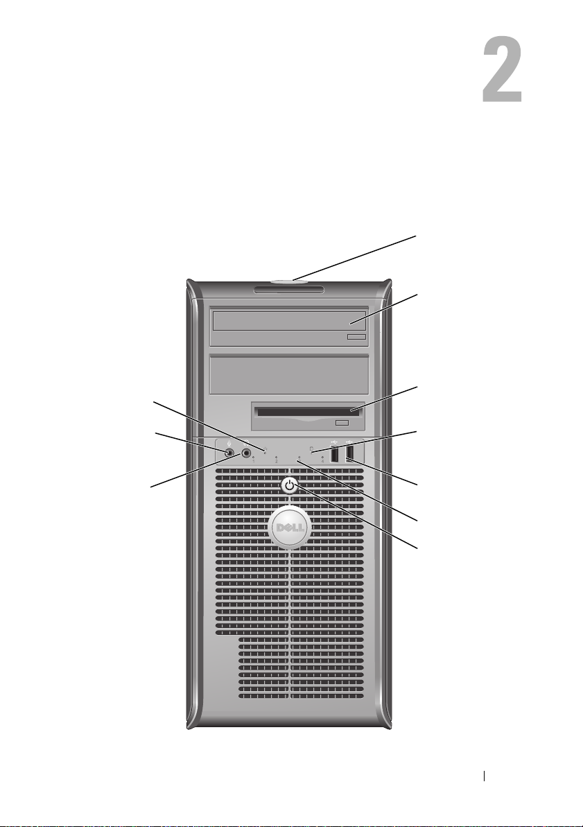
Mini Tower Computer Views
Front View
10
1
2
3
9
8
Mini Tower Computer Views 21
4
5
6
7
Page 22

1 Service Tag Use the Service Tag to identify your computer when you
access the Dell Support website or call Support.
2 optical drive Use the optical drive to play a CD/DVD.
3 floppy drive The floppy drive is optional.
4 drive activity light The drive activity light is on when the computer reads
data from or writes data to the hard drive. The light
might also be on when a device such as an optical drive
is operating.
5 USB 2.0 connectors (2) Use the front USB connectors for devices that you connect
occasionally, such as joysticks or cameras, or for bootable
USB devices (see "System Setup Options" on page 80
for more information on booting to a USB device). It is
recommended that you use the back USB connectors
for devices that typically remain connected, such as
printers and keyboards.
6 diagnostic lights Use these lights to help you troubleshoot a computer
problem based on the diagnostic code. For more
information, see "Diagnostic Lights" on page 106.
7 power button,
power light
8 headphone connector Use the headphone connector to attach headphones
9 microphone connector Use the microphone connector to attach a personal
10 LAN indicator light This light indicates that a LAN (local area network)
Press the power button to turn on the computer.
The light in the center of this button indicates
power state.
NOTICE: To avoid losing data, do not use the
power button to turn off the computer. Instead,
perform an operating system shutdown.
and most kinds of speakers.
computer microphone.
On computers with a sound card, the microphone
connector is on the card.
connection is established.
22 Mini Tower Computer Views
Page 23
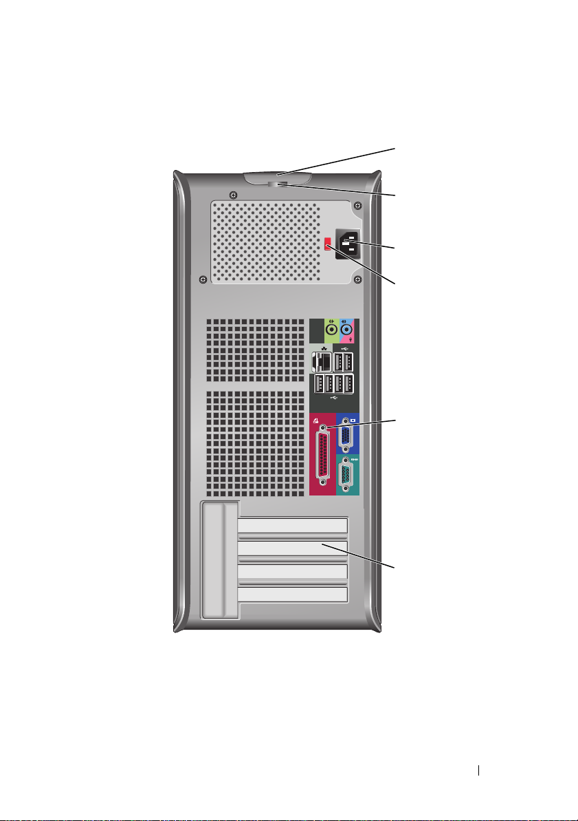
Back View
1
2
3
4
5
6
Mini Tower Computer Views 23
Page 24
1 cover release latch This latch allows you to open the computer cover.
2 padlock rings Padlock rings are for attaching a commercially available
antitheft device. The padlock rings allow you to secure the
computer cover to the chassis with a padlock to prevent
unauthorized access to the inside of the computer. To use
the padlock rings, insert a commercially available padlock
through the rings, and then lock the padlock.
3 power connector Insert the power cable.
4 voltage selector
switch
5 back panel
connectors
6 card slots Access connectors for any installed PCI and PCI Express cards.
CAUTION: Ensure that none of the system air vents are blocked. Blocking them
would cause serious thermal problems.
For selecting voltage rating.
Plug USB, audio, and other devices into the appropriate
connector (see "Back Panel Connectors" on page 24 for
more information.
Back Panel Connectors
24
1
3
98 7
24 Mini Tower Computer Views
5
6
Page 25

1 parallel
connector
2 link integrity light
3 network adapter
connector
4 network activity
light
5 line-out
connector
Connect a parallel device, such as a printer, to the parallel
connector. If you have a USB printer, plug it into a USB
connector.
NOTE: The integrated parallel connector is automatically
disabled if the computer detects an installed card containing a
parallel connector configured to the same address. For more
information, see "System Setup Options" on page 80.
• Green — A good connection exists between a 10-Mbps
network and the computer.
• Orange — A good connection exists between a 100-Mbps
network and the computer.
• Yellow — A good connection exists between a 1-Gbps
(1000-Mbps) network and the computer.
• Off — The computer is not detecting a physical
connection to the network.
To attach your computer to a network or broadband device,
connect one end of a network cable to either a network jack
or your network or broadband device. Connect the other
end of the network cable to the network adapter connector
on the back panel of your computer. A click indicates that
the network cable has been securely attached.
NOTE: Do not plug a telephone cable into the network
connector.
On computers with a network adapter card, use the
connector on the card.
It is recommended that you use Category 5 wiring and
connectors for your network. If you must use Category 3
wiring, force the network speed to 10 Mbps to ensure
reliable operation.
This light flashes yellow when the computer is transmitting
or receiving network data. A high volume of network traffic
may make this light appear to be in a steady "on" state.
Use the green line-out connector to attach headphones and
most speakers with integrated amplifiers.
On computers with a sound card, use the connector on the
card.
Mini Tower Computer Views 25
Page 26

6 microphone/line-
in connector
7 USB 2.0
connectors (6)
8 VGA video
connector
9 serial connector Connect a serial device, such as a handheld device, to the
Use the blue and pink line-in connector to attach a
record/playback device such as a cassette player, CD player,
or VCR; or a personal computer microphone.
Use the back USB connectors for devices that typically
remain connected, such as printers and keyboards.
It is recommended that you use the front USB connectors
for devices that you connect occasionally, such as joysticks or
cameras.
Connect the monitor’s VGA cable to the VGA connector on
the computer.
On computers with a video card, use the connector on the
card.
serial port. The default designation is COM1 for serial
connector 1.
For more information, see "System Setup Options" on
page 80.
26 Mini Tower Computer Views
Page 27

Mini Tower Specifications
NOTE: Offerings may vary by region. For more information regarding the
configuration of your computer, click Start→ Help and Support and select the
option to view information about your computer.
Processor
Processor type Intel
Internal cache up to 6 MB
Front Side Bus frequency 800 MHz and 1066 MHz
System Information
Chipset Intel® G31 Express Chipset w/ICH7R
Data bus width 64 bits
Address bus width 36 bits
DMA channels eight
Interrupt levels 24
BIOS chip (NVRAM) 8 MB
NIC integrated network interface with ASF 1.03
®
Core™ 2 Duo
®
Pentium® Dual Core
Intel
®
Celeron®
Intel
and 2.0 support as defined by DMTF
Capable of 10/100/1000 communication
Memory
Type 667 or 800 MHz DDR2 SDRAM
Memory connectors 2
Memory modules supported 512-MB, 1-GB, or 2-GB non-ECC
Minimum memory dual-channel: 1 GB
single-channel: 512 MB
NOTE: 512 MB is the minimum shipping
configuration.
Mini Tower Computer Views 27
Page 28

Memory (continued)
Maximum memory 4 GB
NOTE: When using 4 GB of memory, the
Microsoft
may report less memory in the system than is
physically installed in the DIMM slots.
BIOS address F0000h
Ports and Connectors
External connectors:
Serial
Parallel
Video
Network adapter
Optional PS/2 with secondary
serial port adapter
USB
Audio
System board connectors:
SATA
Floppy drive
Fan
PCI 2.3
PCI Express
Front Panel
9-pin connector; 16550C-compatible
25-pin connector (bidirectional)
15-pin VGA connector
RJ45 connector
two 6-pin mini-DINs
two front-panel and six back panel USB
2.0–compliant connectors
two connectors for line-in/microphone and
line-out; two front-panel connectors for
headphones and microphone
four 7-pin connectors
34-pin connector
5-pin connector
two 120-pin connectors
one 164-pin (x16) connector
40-pin connector
®
Windows® Operating Systems
28 Mini Tower Computer Views
Page 29

Power
DC power supply:
Wattage
Heat dissipation
NOTE: Power consumption from an AC power
source can be zero when the computer is
unplugged from that power source. However,
the system draws a minute amount of power
from the internal coin cell battery even when
the computer is not drawing power from the
AC power source.
305 W
1041 BTU/hr
NOTE: Heat dissipation is calculated based
upon the power supply rating.
Vo lt ag e
Backup battery 3-V CR2032 lithium coin cell
Controls and Lights
Power control push button
Power light green light — blinking green indicates sleep
hard drive access light green
Link light (on front of chassis) solid green light indicates network
Link integrity light (on integrated
network adapter)
Activity light (on integrated network
adapter)
manual selection power supplies—90 to 135
V at 60 Hz; 180 to 265 V at 50 Hz
mode; solid green indicates power-on state.
amber light — blinking amber indicates a
problem with an installed device; solid
amber indicates an internal power problem
(See "Power Problems" on page 124.)
connection
• green light = 10 Mbps
• orange light = 100 Mbps
• yellow light = 1000 Mbps (1 Gbs)
yellow blinking light
Mini Tower Computer Views 29
Page 30

Controls and Lights
Diagnostic lights four lights on the front panel (See
"Diagnostic Lights" on page 106.)
Standby power light AUX_PWR on the system board
Expansion Bus
Bus type PCI 2.3
PCI Express 1.0A
SATA 1.0A and 2.0
USB 2.0
Bus speed PCI: 133 MB/s
PCI Express x16: 8 GB/s bidirectional speed
SATA: 1.5 Gbps and 3.0 Gbps
USB: 480 Mbps
Cards: full-height cards supported
PCI:
connectors
connector size
connector data width
(maximum)
PCI Express:
connectors
power
connector size
connector data width
(maximum)
two
two 120 pin connectors
32 bits
one x16
25 W (x16) maximum
164 pins (x16)
16 PCI Express lanes (x16)
Communications
Network adapter 10/100/1000 Ethernet LAN on system board
30 Mini Tower Computer Views
Page 31

Drives
Externally accessible
Available devices
Internally accessible
Video
Ty p e
Audio
Type ADI 1984 High Definition Audio
Physical
Height
Width
Depth
We ig ht
• one 3.5-inch drive
• two 5.25-inch drive bays
• hard drive, DVD+/-RW drive, DVDROM, CD-RW drive, floppy drive
• two bays for 1-inch-high hard drives
• Intel G31 (integrated on system board)
• PCI Express x16 slot can support either a
PCI Express graphics card or a DVI
graphics card (for dual-monitor support)
41.4 cm (16.3 inches)
18.5 cm (7.3 inches)
43.9 cm (17.3 inches)
12.34 kg (27.2 lb)
Environmental
Temperature:
Operating
Storage
Relative humidity 20% to 80% (noncondensing)
Maximum vibration:
Operating
10° to 35°C (50° to 95°F)
–40° to 65°C (–40° to 149°F)
5 to 350 Hz at 0.0002 G2/Hz
Mini Tower Computer Views 31
Page 32

Environmental (continued)
Storage
Maximum shock:
Operating
Storage
Altitude:
Operating
Storage
5 to 500 Hz at 0.001 to 0.01 G2/Hz
40 G +/- 5% with pulse duration of 2 msec
+/- 10% (equivalent to 51 cm/sec
[20 in/sec])
105 G +/- 5% with pulse duration of 2 msec
+/- 10% (equivalent to 127 cm/sec
[50 in/sec])
–15.2 to 3048 m (–50 to 10,000 ft)
–15.2 to 10,668 m (–50 to 35,000 ft)
32 Mini Tower Computer Views
Page 33

Desktop Computer Views
Front View
1
11
1 USB 2.0 connectors (2) Use the front USB connectors for devices that you connect
occasionally, such as joysticks or cameras, or for bootable
USB devices (see "System Setup Options" on page 80
for more information on booting to a USB device). It is
recommended that you use the back USB connectors
for devices that typically remain connected, such as
printers and keyboards.
2 drive activity light The drive activity light is on when the computer reads
data from or writes data to the hard drive. The light
might also be on when a device such as an optical drive
is operating.
3 power button,
power light
Press the power button to turn on the computer.
The light in the center of this button indicates
power state.
89
2
7
3
5
4610
NOTICE: To avoid losing data, do not use the
power button to turn off the computer. Instead,
perform an operating system shutdown.
Desktop Computer Views 33
Page 34

4 Dell badge This badge can be rotated to match the orientation of
your computer. To rotate the badge, place your fingers
around the outside of the badge, press firmly, and turn
the badge. You can also rotate the badge using the slot
provided near the bottom of the badge.
5 power light The power light illuminates and blinks or remains solid
to indicate different operating states:
• No light — The computer is turned off.
• Steady green — The computer is in a normal
operating state.
• Blinking green — The computer is in a power-saving
mode.
• Blinking or solid amber — See "Power Problems" on
page 124.
To exit from a power-saving mode, press the power
button or use the keyboard or the mouse if it is
configured as a wake device in the Windows Device
Manager. For more information about sleep modes and
exiting from a power-saving mode, see "Power
Management" on page 66.
See "Diagnostic Lights" on page 106 for a description
of light codes that can help you troubleshoot problems
with your computer.
6 diagnostic lights Use the lights to help you troubleshoot a computer
problem based on the diagnostic code. For more
information, see "Diagnostic Lights" on page 106.
7 LAN indicator light This light indicates that a LAN (local area network)
connection is established.
8 headphone and
microphone
connectors
9 floppy drive The floppy drive is optional.
10 optical drive Use the optical drive to play a CD/DVD.
11 Service Tag Use the Service Tag to identify your computer when you
Use the microphone connector to attach a personal
computer microphone. On computers with a sound
card, the microphone connector is on the card.
Use the headphone connector to attach headphones
and most kinds of speakers.
access the Dell Support website or call Support.
34 Desktop Computer Views
Page 35

Back View
1
1 card slots Access connectors for any installed PCI and PCI Express cards.
2 back panel
connectors
3 power connector Insert the power cable.
4 voltage selector
switch
5 padlock rings Padlock rings are for attaching a commercially available
6 cover release latch Use this latch to open the computer cover.
2 3 4 6
Plug USB, audio, and other devices into the appropriate
connector (see "Back Panel Connectors" on page 36 for
more information).
For selecting voltage rating.
antitheft device. The padlock rings allow you to secure the
computer cover to the chassis with a padlock to prevent
unauthorized access to the inside of the computer. To use
the padlock rings, insert a commercially available padlock
through the rings, and then lock the padlock.
5
CAUTION: Ensure that none of the system air vents are blocked. Blocking them
would cause serious thermal problems.
Desktop Computer Views 35
Page 36

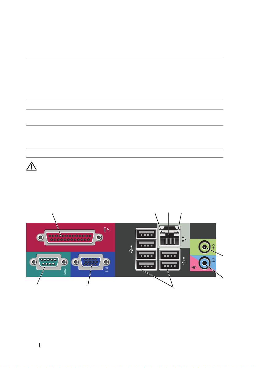
Back Panel Connectors
13
98 7
1 parallel
connector
Connect a parallel device, such as a printer, to the parallel
connector. If you have a USB printer, plug it into a USB
connector.
24
NOTE: The integrated parallel connector is automatically
disabled if the computer detects an installed card containing a
parallel connector configured to the same address. For more
information, see "System Setup Options" on page 80.
2 link integrity
light
• Green — A good connection exists between a 10-Mbps
network and the computer.
• Orange — A good connection exists between a 100-Mbps
network and the computer.
• Yellow — A good connection exists between a 1-Gbps
(1000-Mbps) network and the computer.
• Off — The computer is not detecting a physical
connection to the network.
5
6
36 Desktop Computer Views
Page 37

3 network adapter
connector
4 network activity
light
5 line-out
connector
6 microphone/line-
in connector
7 USB 2.0
connectors (6)
To attach your computer to a network or broadband device,
connect one end of a network cable to either a network jack
or your network or broadband device. Connect the other
end of the network cable to the network adapter connector
on the back panel of your computer. A click indicates that
the network cable has been securely attached.
NOTE: Do not plug a telephone cable into the network
connector.
On computers with a network adapter card, use the
connector on the card.
It is recommended that you use Category 5 wiring and
connectors for your network. If you must use Category 3
wiring, force the network speed to 10 Mbps to ensure
reliable operation.
This light flashes yellow when the computer is transmitting
or receiving network data. A high volume of network traffic
may make this light appear to be in a steady "on" state.
Use the green line-out connector to attach headphones and
most speakers with integrated amplifiers.
On computers with a sound card, use the connector on the
card.
Use the blue line-in connector to attach a record/playback
device such as a cassette player, CD player, or VCR.
Use the pink microphone connector to attach a personal
computer microphone.
On computers with a sound card, use the connector on the
card.
Use the back USB connectors for devices that typically
remain connected, such as printers and keyboards.
It is recommended that you use the front USB connectors
for devices that you connect occasionally, such as joysticks or
cameras.
Desktop Computer Views 37
Page 38

8 VGA video
connector
9 serial connector Connect a serial device, such as a handheld device, to the
Connect the monitor’s VGA cable to the VGA connector on
the computer.
On computers with a video card, use the connector on the
card.
serial port. The default designation is COM1 for serial
connector 1.
For more information, see "System Setup Options" on
page 80.
38 Desktop Computer Views
Page 39

Desktop Computer Specifications
NOTE: Offerings may vary by region. For more information regarding the
configuration of your computer, click Start→ Help and Support and select the
option to view information about your computer.
Processor
Processor type
Internal cache Up to 6 MB
External bus frequency 800 MHz and 1066 MHz
System Information
Chipset Intel G31 Chipset w/ICH7R
Data bus width 64 bits
Address bus width 36 bits
DMA channels eight
Interrupt levels 24
BIOS chip (NVRAM) 8 MB
NIC integrated network interface with ASF 1.03
• Intel Core 2 Duo
• Intel Pentium®
• Intel Celeron®
and 2.0 support as defined by DMTF
Capable of 10/100/1000 communication
Memory
Type 667 or 800 MHz DDR2 SDRAM
Memory connectors 2
Memory modules supported 512 MB, 1 GB, or 2 GB non-ECC
Minimum memory dual-channel: 1 GB
single-channel: 512 MB
NOTE: 512 MB is the minimum shipping
configuration.
Desktop Computer Views 39
Page 40

Memory (continued)
Maximum memory 4 GB
NOTE: When using 4 GB of memory, the
Microsoft
may report less memory in the system than is
physically installed in the DIMM slots.
Ports and Connectors
External connectors:
Serial
Parallel
Video
Network adapter
Optional PS/2 with secondary serial
port adapter
USB
Audio
System board connectors:
SATA
Floppy drive
Fan
PCI 2.3
PCI Express
Front Panel
9-pin connector; 16550C-compatible
25-pin connector (bidirectional)
15-pin VGA connector
RJ45 connector
two 6-pin mini-DINs
two front-panel and six back panel USB
2.0–compliant connectors
two connectors for line-in/microphone and
line-out; two front-panel connectors for
headphones and microphone
four 7-pin connectors
34-pin connector
5-pin connector
two 120-pin connectors
one 164-pin (x16) connector
40-pin connector
®
Windows® Operating Systems
40 Desktop Computer Views
Page 41

Power
DC power supply:
Wattage
Heat dissipation
NOTE: Power consumption from an AC power
source can be zero when the computer is
unplugged from that power source, but the
internal battery does draw a minute amount of
power from the power supply even when the
computer is not drawing power from the AC
power source.
280 W
955 BTU/hr
NOTE: Heat dissipation is calculated based
upon the power supply rating.
Vo lt ag e
Backup battery 3-V CR2032 lithium coin cell
Controls and Lights
Power control push button
Power light green light — blinking green indicates a
hard drive access light green
Link light solid green light indicates network
Link integrity light (on integrated
network adapter)
Activity light (on integrated network
adapter)
manual selection power supplies — 90 to
135 V at 50/60 Hz; 180 to 265 V at 50/60 Hz
sleep mode; solid green indicates a power-on
state.
amber light — blinking amber indicates a
problem with an installed device; solid
amber indicates an internal power problem
(See "Power Problems" on page 124.)
connection
• green light = 10 Mbps
• orange light = 100 Mbps
• yellow light = 1000 Mbps (1 Gbs)
yellow blinking light
Desktop Computer Views 41
Page 42

Controls and Lights
Diagnostic lights four lights on the front panel (See
"Diagnostic Lights" on page 106.)
Standby power light AUX_PWR on the system board
Communications
Network adapter 10/100/1000 Ethernet LAN on system board
Expansion Bus
Bus type PCI 2.3
PCI Express 1.0A
SATA 1.0A and 2.0
USB 2.0
Bus speed PCI: 133 MB/s
PCI Express x16: 8 GB/s bidirectional speed
SATA: 1.5 Gbps and 3.0 Gbps
USB: 480 Mbps
Cards standard configuration supports low-profile
cards only;
with optional riser-card cage, computer
supports half-length, full-height cards. Fullheight cards are supported in the 6.875-inch
riser card cage.
PCI: without riser-card cage
connectors
card size
connector size
connector data width
(maximum)
PCI Express: without riser-card
cage
connectors
card size
power
two
low profile
120 pins
32 bits
one x16
low profile
25 W (maximum)
42 Desktop Computer Views
Page 43

Expansion Bus
connector size
connector data width
(maximum)
PCI and PCI Express: with
optional, full-height PCI Express
riser-card cage, supporting both
low-profile and full-height cards
PCI
connectors
card size
connector size
connector data width
(maximum)
PCI Express
connectors
card size
power
connector size
connector data width
(maximum)
PCI only: with optional, full-height
PCI riser-card cage, supporting
both low-profile and full-height
cards
connectors
card size
connector size
connector data width
(maximum)
164 pins (x16)
16 PCI Express lanes (x16)
two
one low-profile card and one full-height card
120 pins
32 bits
one x16
full-height
25 W maximum
164 pins (x16)
16 PCI Express lanes (x16)
three PCI
one low-profile card and two full-height
cards
120 pins
32 bits
Desktop Computer Views 43
Page 44

Drives
Externally accessible
Available devices
Internally accessible
Video
Ty p e
Audio
Type ADI 1984 High Definition Audio
Stereo conversion 24-bit analog-to-digital; 24-bit digital-to-
Physical
Height 11.4 cm (4.5 inches)
Width 39.9 cm (15.7 inches)
Depth 35.3 cm (13.9 inches)
Weight 10.4 kg (23 pounds)
• one 3.5-inch drive
• one bay for CD/DVD or optional second
hard drive
• hard drive, DVD+/-RW drive, DVDROM, CD-RW drive, Floppy drive
• one bay for 5.25-inch (1-inch-high) hard
drive
• Intel G31 (integrated on system board)
• PCI Express x16 slot can support either a
PCI Express graphics card or a DVI
graphics card (for dual-monitor support)
analog
Environmental
Temperature:
Operating
Storage
Relative humidity 20% to 80% (noncondensing)
10° to 35°C (50° to 95°F)
–40° to 65°C (–40° to 149°F)
44 Desktop Computer Views
Page 45

Environmental (continued)
Maximum vibration:
Operating
Storage
Maximum shock:
Operating
Storage
Altitude:
Operating
Storage
0.25 G at 3 to 200 Hz at 0.5 octave/min
0.5 G at 3 to 200 Hz at 1 octave/min
40 G +/- 5% with pulse duration of 2 msec
+/- 10% (equivalent to 51 cm/sec
[20 in/sec])
105 G +/- 5% with pulse duration of 2 msec
+/- 10% (equivalent to 127 cm/sec
[50 in/sec])
–15.2 to 3048 m (–50 to 10,000 ft)
–15.2 to 10,668 m (–50 to 35,000 ft)
Desktop Computer Views 45
Page 46

46 Desktop Computer Views
Page 47

Setting Up Your Computer
Installing Your Computer in an Enclosure
Installing your computer in an enclosure can restrict the airflow and impact
your computer’s performance, possibly causing it to overheat. Follow the
guidelines below when installing your computer in an enclosure:
NOTICE: The operating temperature specifications indicated in this manual reflect
the maximum ambient operating temperature. The room ambient temperature
needs to be a consideration when installing your computer in an enclosure. For
example, if the ambient room temperature is at 25°C (77°F), depending on your
computer’s specifications, you only have 5° to 10°C (9° to 18°F) temperature margin
before you reach your computer’s maximum operating temperature. For details
about your computer’s specifications, see "Desktop Computer Specifications" on
page 39 or "Mini Tower Specifications" on page 27.
• Leave a 10.2 cm (4 in) minimum clearance on all vented sides of the
computer to permit the airflow required for proper ventilation.
• If your enclosure has doors, they need to be of a type that allows at least
30 percent airflow through the enclosure (front and back).
Setting Up Your Computer 47
Page 48

• If your computer is installed in a corner on a desk or under a desk, leave at
least 5.1 cm (2 in) clearance from the back of the computer to the wall to
permit the airflow required for proper ventilation.
48 Setting Up Your Computer
Page 49

NOTICE: Do not install your computer in an enclosure that does not allow airflow.
Restricting the airflow impacts your computer’s performance, possibly causing it to
overheat.
Setting Up a Home and Office Network
Connecting to a Network Adapter
To connect a network cable:
NOTE: Plug the network cable into the network adapter connector on the
computer. Do not plug the network cable into the modem connector on the
computer. Do not plug a network cable into a telephone wall jack.
1
Connect the network cable to the network adapter connector on the back
of your computer.
Insert the cable until it clicks into place, and then gently pull it to ensure
that it is secure.
2
Connect the other end of the network cable to a network device.
Setting Up Your Computer 49
Page 50

network
adapter
connector
network
device
network adapter connector on computer
network cable
Network Setup
Windows XP
The Microsoft® Windows® XP operating system provides a Network Setup
Wizard to guide you through the process of sharing files, printers, or an
Internet connection between computers in a home or small office.
1
Click the
Communications
2
On the
3
Click
NOTE: Selecting the connection method This computer connects directly to the
Internet enables the integrated firewall provided with Windows XP Service Pack 1
(SP1) or later.
4
Complete the checklist and required preparations.
5
Return to the Network Setup Wizard and follow the instructions on the
screen.
Windows Vista
To make changes to your network setup in Microsoft® Windows Vista™:
Start
button, point to
, and then click
Network Setup Wizard
All Programs→ Accessories→
Network Setup Wizard
welcome screen, click
Checklist for creating a network
.
Next
.
.
50 Setting Up Your Computer
Page 51

1
Click the Windows Vista Start button, , and then click
Network and Sharing Center.
2
Click
Set up a connection or network
3
Select the type of network connection you want to make and follow the
instructions on the screen.
4
When finished, close the Network and Sharing Center.
.
Network→
Connecting to the Internet
NOTE: ISPs and ISP offerings vary by country.
To connect to the Internet, you need a modem or network connection and an
Internet service provider (ISP). Your ISP will offer one or more of the
following Internet connection options:
• DSL connections that provide high-speed Internet access through your
existing telephone line or cellular telephone service. With a DSL
connection, you can access the Internet and use your telephone on the
same line simultaneously.
• Cable modem connections that provide high-speed Internet access
through your local cable TV line.
• Satellite modem connections that provide high-speed Internet access
through a satellite television system.
• Dial-up connections that provide Internet access through a telephone line.
Dial-up connections are considerably slower than DSL and cable (or
satellite) modem connections.
• Wireless LAN connections that provide Internet access using Bluetooth
wireless technology.
If you are using a dial-up connection, connect a telephone line to the modem
connector on your computer and to the telephone wall jack before you set up
your Internet connection. If you are using a DSL or cable/satellite modem
connection, contact your ISP or cellular telephone service for setup
instructions.
®
Setting Up Your Internet Connection
To set up an Internet connection with a provided ISP desktop shortcut:
Setting Up Your Computer 51
Page 52

1
Save and close any open files, and exit any open programs.
2
Double-click the ISP icon on the Microsoft® Windows® desktop.
3
Follow the instructions on the screen to complete the setup.
If you do not have an ISP icon on your desktop or if you want to set up an
Internet connection with a different ISP, perform the steps in the following
section that corresponds to the operating system your computer is using.
NOTE: If you are having problems connecting to the Internet, see "Setting Up a
Home and Office Network" on page 49. If you cannot connect to the Internet but
have successfully connected in the past, the ISP might have a service outage.
Contact your ISP to check the service status, or try connecting again later.
Windows XP
1
Save and close any open files, and exit any open programs.
2
Click
Start→
The
New Connection Wizard
3
Click
Connect to the Internet
4
In the next window, click the appropriate option:
• If you do not have an ISP and want to select one, click
list of Internet service providers (ISPs)
Internet Explorer
.
appears.
.
Choose from a
.
• If you have already obtained setup information from your ISP but you
did not receive a setup CD, click
• If you have a CD, click
5
Click
Next
.
If you selected
Set up my connection manually
Use the CD I got from an ISP
Set up my connection manually
.
, continue to step 6.
.
Otherwise, follow the instructions on the screen to complete the setup.
NOTE: If you do not know which type of connection to select, contact your ISP.
6
Click the appropriate option under
Internet?
7
Use the setup information provided by your ISP to complete the setup.
Windows Vista™
NOTE: Have your ISP information ready. If you do not have an ISP, the Connect to
the Internet wizard can help you get one.
, and then click
Next
How do you want to connect to the
.
52 Setting Up Your Computer
Page 53

1
Save and close any open files, and exit any open programs.
2
Click the Windows Vista Start button , and click
3
Under
Network and Internet,
Connect to the Internet
The
4
Click either
to connect:
•Choose
modem, or Bluetooth wireless technology connection.
• Chose
NOTE: If you do not know which type of connection to select, click Help me choose
or contact your ISP.
5
Follow the instructions on the screen and use the setup information
provided by your ISP to complete the setup.
Broadband (PPPoE)
Broadband
Dial-up
if you will use a dial-up modem or ISDN.
click
Connect to the Internet
window appears.
or
Dial-up
if you will use a DSL, satellite modem, cable TV
, depending on how you want
Control Panel
.
.
Transferring Information to a New Computer
You can use your operating system "wizards" to help you transfer files and
other data from one computer to another—for example, from an old
computer to a new computer. For instructions, see the following section that
corresponds to the operating system that your computer is running.
Microsoft® Windows® XP (Optional)
The Microsoft Windows XP operating system provides the Files and Settings
Transfer Wizard to move data from a source computer to a new computer.
You can transfer data, such as:
• E-mail messages
• Toolbar settings
• Window sizes
• Internet bookmarks
You can transfer the data to the new computer over a network or serial
connection, or you can store it on removable media, such as a writable CD,
for transfer to the new computer.
Setting Up Your Computer 53
Page 54

NOTE: You can transfer information from an old computer to a new computer by
directly connecting a serial cable to the input/output (I/O) ports of the two
computers. To transfer data over a serial connection, you must access the Network
Connections utility from the Control Panel and perform additional configuration
steps, such as setting up an advanced connection and designating the host
computer and the guest computer.
For instructions on setting up a direct cable connection between two computers,
see Microsoft Knowledge Base Article #305621, titled How to Set Up a Direct Cable
Connection Between Two Computers in Windows XP. This information may not be
available in certain countries.
For transferring information to a new computer, you must run the Files and
Settings Transfer Wizard. You can use the optional Operating System media
for this process or you can create a wizard disk with the Files and Settings
Transfer Wizard.
Running the Files and Settings Transfer Wizard With the Operating System Media
NOTE: This procedure requires the Operating System media. This media is optional
and may not be included with certain computers.
To prepare a new computer for the file transfer:
1
Open the Files and Settings Transfer Wizard: click
Accessories→ System Tools→
2
When the
click
3
On the
4
On the
Files and Settings Transfer Wizard
Next
.
Which computer is this?
Do you have a Windows XP CD?
from the Windows XP CD
5
When the
source computer. Do
Now go to your old computer
not
Files and Settings Transfer Wizard
screen, click
screen, click
→ Next
.
screen appears, go to your old or
click
Next
at this time.
Start→
All Programs→
.
welcome screen appears,
New Computer→
Next
.
I will use the wizard
To copy data from the old computer:
1
On the old computer, insert the Windows XP
2
On the
additional tasks
3
Under
4
On the
Welcome to Microsoft Windows XP
.
What do you want to do?
Which computer is this?
, click
screen, click
Operating System
screen, click
media.
Perform
Transfer files and settings→ Next
Old Computer→
Next
.
.
54 Setting Up Your Computer
Page 55

5
On the
Select a transfer method
screen, click the transfer method you
prefer.
6
On the
transfer and click
After the information has been copied, the
Phase
7
Click
What do you want to transfer?
Next
.
screen appears.
Finish
.
screen, select the items you want to
Completing the Collection
To transfer data to the new computer:
1
On the
Next
2
On the
chose for transferring your settings and files and click
Now go to your old computer
.
Where are the files and settings?
screen on the new computer, click
screen, select the method you
Next
.
The wizard reads the collected files and settings and applies them to your
new computer.
When all of the settings and files have been applied, the
Finished
screen
appears.
3
Click
Finished
Running the Files and Settings Transfer Wizard Without the Operating System
Media
and restart the new computer.
To run the Files and Settings Transfer Wizard without the Operating System
media, you must create a wizard disk that will allow you to create a backup
image file to removable media.
To create a wizard disk, use your new computer with Windows XP and
perform the following steps:
1
Open the Files and Settings Transfer Wizard: click
Accessories→ System Tools→
2
When the
click
3
On the
4
On the
Files and Settings Transfer Wizard
Next
.
Which computer is this?
Do you have a Windows XP CD?
Wizard Disk in the following drive
5
Insert the removable media, such as a writable CD, and click OK.
Files and Settings Transfer Wizard
screen, click
screen, click
→
Next.
Setting Up Your Computer 55
Start→
All Programs→
.
welcome screen appears,
New Computer→
Next
.
I want to create a
Page 56

6
When the disk creation completes and the
computer
7
Go to the old computer.
message appears,
do not
Now go to your old
click
Next
.
To copy data from the old computer:
1
On the old computer, insert the wizard disk.
2
Click
Start→
3
In the
the appropriate removable media) and click
4
On the
5
On the
6
On the
Run
.
Open
field on the
Run
window, browse to the path for
Files and Settings Transfer Wizard
Which computer is this?
Select a transfer method
screen, click
screen, click the transfer method you
fastwiz
OK
.
welcome screen, click
Old Computer→
prefer.
7
On the
transfer and click
After the information has been copied, the
Phase
8
Click
What do you want to transfer?
Next
.
screen appears.
Finish
.
screen, select the items you want to
Completing the Collection
To transfer data to the new computer:
1
On the
Next
2
On the
chose for transferring your settings and files and click
Now go to your old computer
.
Where are the files and settings?
screen on the new computer, click
screen, select the method you
Next
. Follow the
instructions on the screen.
The wizard reads the collected files and settings and applies them to your
new computer.
Next
Next
(on
.
.
When all of the settings and files have been applied, the
Finished
appears.
3
Click
Finished
NOTE: For more information about this procedure, search support.dell.com for
document #154781 (What Are The Different Methods To Transfer Files From My Old
Computer To My New Dell™ Computer Using the Microsoft
Operating System?).
and restart the new computer.
®
Windows® XP
56 Setting Up Your Computer
screen
Page 57

NOTE: Access to the Dell™ Knowledge Base document may not be available in
certain countries.
Microsoft Windows Vista™ (Optional)
1
Click the Windows Vista Start button , and then click
and settings
2
In the
3
Click
Follow the instructions provided on the screen by the Windows Easy Transfer
wizard.
→ Start Windows Easy Transfer.
User Account Control
Start a new transfer
dialog box, click
or
Continue a transfer in progress
Continue
Transfer files
.
.
Setting Up a Printer
NOTICE: Complete the operating system setup before you connect a printer to the
computer.
See the documentation that came with the printer for setup information,
including how to:
• Obtain and install updated drivers.
• Connect the printer to the computer.
• Load paper and install the toner or ink cartridge.
For technical assistance, refer to the printer owner's manual or contact the
printer manufacturer.
Printer Cable
Your printer connects to your computer with either a USB cable or a parallel
cable. Your printer may not come with a printer cable, so if you purchase a
cable separately, ensure that it is compatible with your printer and computer.
If you purchased a printer cable at the same time you purchased your
computer, the cable may arrive in the computer’s shipping box.
Connecting a USB Printer
NOTE: You can connect USB devices while the computer is turned on.
1
Complete the operating system setup if you have not already done so.
Setting Up Your Computer 57
Page 58

2
Attach the USB printer cable to the USB connectors on the computer and
the printer. The USB connectors fit only one way.
1
2
3
1 USB connector on computer 2 USB connector on printer
3 USB printer cable
3
Turn on the printer and then turn on the computer.
4
Depending on your computer’s operating system, a printer wizard may be
available to help you install the printer driver:
If your computer is running the Microsoft® Windows® XP operating system
and the
Add New Hardware Wizard
window appears, click
If your computer is running the Windows Vista™ operating system
Windows Vista Start button , and click
Network→ Add a printer
start the Add Printer Wizard.
58 Setting Up Your Computer
Cancel
, click the
.
to
Page 59

5
Install the printer driver if necessary. See "Reinstalling Drivers and
Utilities" on page 134, and the documentation that came with your printer.
Connecting a Parallel Printer
1
Complete the operating system setup, if you have not already done so.
2
Turn off the computer (see "Turning Off Your Computer" on page 143).
NOTICE: For best results, use a 3-m (10-ft) or shorter parallel cable.
3
Attach the parallel printer cable to the parallel connector on the computer
and tighten the two screws. Attach the cable to the connector on the
printer and snap the two clips into the two notches.
1
2
6
5
1 parallel connector on computer 2 connector on printer
3 clips (2) 4 notches
5 parallel printer cable 6 screws (2)
4
Setting Up Your Computer 59
3
Page 60

4
Turn on the printer and then turn on the computer. If the
Hardware Wizard
5
Install the printer driver if necessary. See the documentation that came
window appears, click
Cancel
.
Add New
with your printer for instructions.
Connecting Two Monitors
CAUTION: Before you begin any of the procedures in this section, follow the
safety instructions in the Product Information Guide.
If you purchased a graphics card that supports dual monitors, follow these
instructions to connect and enable your monitors. The instructions tell you
how to connect either two monitors (each with a VGA connector), one monitor
with a VGA connector and one monitor with a DVI connector, or a TV.
NOTICE: If you are connecting two monitors that have VGA connectors, you must
have the optional DVI adapter to connect the cable. If you are connecting two
flat-panel monitors, at least one of them must have a VGA connector. If you are
connecting a TV, you may connect only one monitor (VGA or DVI) in addition to the TV.
Connecting Two Monitors With VGA Connectors
1
Shutdown your system.
NOTE: If your computer has integrated video, do not connect either monitor to the
integrated video connector. If the integrated video connector is covered by a cap,
do not remove the cap to connect the monitor or the monitor will not function.
2
Connect one of the monitors to the VGA (blue) connector on the back of
the computer.
3
Connect the other monitor to the optional DVI adapter and connect the
DVI adapter to the DVI (white) connector on the back of the computer.
4
Restart your system.
60 Setting Up Your Computer
Page 61

1
4
1 optional DVI adapter 2 DVI (white) connector
3 TV-OUT connector 4 VGA (blue) connector
23
Connecting One Monitor With a VGA Connector and One Monitor With a DVI Connector
1
Shutdown your system.
2
Connect the VGA connector on the monitor to the VGA (blue) connector
on the back of the computer.
3
Connect the DVI connector on the other monitor to the DVI (white)
connector on the back of the computer.
4
Restart your system.
Setting Up Your Computer 61
Page 62

Connecting a TV
NOTE: You must purchase an S-video cable, available at most consumer electronics
stores, to connect a TV to your computer. It is not included with your computer.
1
Shutdown your system.
2
Connect one end of the S-video cable to the optional TV-OUT connector
on the back of the computer.
3
Connect the other end of the S-video cable to the S-video input connector
on your TV.
4
Connect the VGA or DVI monitor.
5
Restart your system.
Changing the Display Settings
1
After you connect the monitor(s) or TV, turn on the computer.
The Microsoft
2
Enable extended desktop mode in the display settings. In extended
desktop mode, you can drag objects from one screen to the other,
effectively doubling the amount of viewable work space.
®
Windows® desktop displays on the primary monitor.
Power Protection Devices
Several devices are available to protect against power fluctuations and
failures:
• Surge protectors
• Line conditioners
• Uninterruptible power supplies (UPS)
Surge Protectors
Surge protectors and power strips equipped with surge protection help
prevent damage to your computer from voltage spikes that can occur during
electrical storms or after power interruptions. Some surge protector
manufacturers include warranty coverage for certain types of damage.
Carefully read the device warranty when choosing a surge protector. A device
with a higher joule rating offers more protection. Compare joule ratings to
determine the relative effectiveness of different devices.
62 Setting Up Your Computer
Page 63

NOTICE: Most surge protectors do not protect against power fluctuations or
power interruptions caused by nearby lightning strikes. When lightning occurs in
your area, disconnect the telephone line from the telephone wall jack and
disconnect your computer from the electrical outlet.
Many surge protectors have a telephone jack for modem protection. See the
surge protector documentation for modem connection instructions.
NOTICE: Not all surge protectors offer network adapter protection. Disconnect the
network cable from the network wall jack during electrical storms.
Line Conditioners
NOTICE: Line conditioners do not protect against power interruptions.
Line conditioners are designed to maintain AC voltage at a fairly constant
level.
Uninterruptible Power Supplies
NOTICE: Loss of power while data is being saved to the hard drive may result in
data loss or file damage.
NOTE: To ensure maximum battery operating time, connect only your computer to
a UPS. Connect other devices, such as a printer, to a separate power strip that
provides surge protection.
A UPS protects against power fluctuations and interruptions. UPS devices
contain a battery that provides temporary power to connected devices when
AC power is interrupted. The battery charges while AC power is available. See
the UPS manufacturer documentation for information on battery operating
time and to ensure that the device is approved by Underwriters Laboratories
(UL).
Setting Up Your Computer 63
Page 64

64 Setting Up Your Computer
Page 65

Advanced Features
LegacySelect Technology Control
LegacySelect technology control offers legacy-full, legacy-reduced, or legacyfree solutions based on common platforms, hard-drive images, and help desk
procedures. Control is provided to the administrator through system setup,
Dell OpenManage™ IT Assistant, or Dell custom factory integration.
LegacySelect allows administrators to electronically activate or deactivate
connectors and media devices that include serial and USB connectors, a
parallel connector, a floppy drive, PCI slots, and a PS/2 mouse. Connectors
and media devices that are deactivated make resources available. You must
restart the computer to effect the changes.
Manageability
Dell OpenManage™ IT Assistant
IT Assistant configures, manages, and monitors computers and other devices
on a corporate network. IT Assistant manages assets, configurations, events
(alerts), and security for computers equipped with industry-standard
management software. It supports instrumentation that conforms to SNMP,
DMI, and CIM industry standards.
Dell OpenManage Client instrumentation, which is based on DMI and CIM,
is available for your computer. For information on IT Assistant, see the Dell
OpenManage IT Assistant User’s Guide available on the Dell Support website
at support.dell.com.
Dell OpenManage Client Instrumentation
Dell OpenManage Client Instrumentation is software that enables remote
management programs such as IT Assistant to do the following:
Advanced Features 65
Page 66

• Access information about your computer, such as how many processors it
has and what operating system it is running.
• Monitor the status of your computer, such as listening for thermal alerts
from temperature probes or hard-drive failure alerts from storage devices.
• Change the state of your computer, such as updating its BIOS or shutting
it down remotely.
A managed system is one that has Dell OpenManage Client Instrumentation
set up on a network that uses IT Assistant. For information about Dell
OpenManage Client Instrumentation, see the Dell OpenManage Client
Instrumentation User’s Guide available on the Dell Support website at
support.dell.com.
Power Management
Your computer can be set to use less power when you are not working. You
control the power usage through the operating system installed on your
computer and certain option settings in system setup. These periods of
reduced power are called "sleep modes," in Windows Vista™, and "standby," in
Windows
•
•
•
®
.
XP
NOTE: All components installed in the computer must support the hibernate and/or
standby mode feature(s) and have the appropriate drivers loaded to enter either of
these sleep modes. For more information, see the manufacturer’s documentation
for each component.
Standby
. In this sleep mode, power is reduced or turned off for most
components, including the cooling fans. However, system memory remains
active.
Hibernate
. This sleep mode reduces power consumption to a minimum by
writing all data in system memory to a hard drive and then removing
system power. Waking up from this mode restarts the computer, and the
memory contents are restored. Operation then resumes where the
computer left off when it entered the hibernation mode.
Shutdown
. This sleep mode removes all power from the computer except a
small auxiliary amount. As long as the computer remains connected to an
electrical outlet, it can be automatically or remotely started. For example,
the
Auto Power On
option in system setup allows the computer to
66 Advanced Features
Page 67

automatically start at a specified time. Also, your network administrator
can remotely start your computer using a power management event such
as Remote Wake Up.
The following table lists the sleep modes and the methods you can use to
wake the computer from each mode.
Sleep Mode Wake-Up Methods (Windows XP)
Standby
Hibernate
Shutdown
NOTE: For more information on power management, see your operating system
documentation.
• Press the power button
• Auto power on
• Move or click the mouse
• Type on the keyboard
• USB device activity
• Power management event
• Press the power button
• Auto power on
• Power management event
• Press the power button
• Auto power on
• Power management event
Advanced Features 67
Page 68

68 Advanced Features
Page 69

Using Multimedia
Playing CDs or DVDs
NOTICE: Do not press down on the CD/DVD tray when you open or close it. Keep
the tray closed when you are not using the drive.
NOTICE: Do not move the computer while playing CDs or DVDs.
1
Press the eject button on the front of the drive.
2
Place the disc, label side up, in the center of the tray.
3
Press the eject button or gently push in the tray.
To format CDs for storing data, to create music CDs, or to copy CDs, see the
CD software that came with your computer.
NOTE: Ensure that you follow all copyright laws when you create CDs.
A CD player includes the following basic buttons:
Play.
Move backward within the current track.
Pause.
Advanced Features 69
Page 70

Move forward within the current track.
Stop.
Go to the previous track.
Eject.
Go to the next track.
A DVD player includes the following basic buttons:
Stop.
Restart the current chapter.
Play.
Fast forward.
Pause.
Fast reverse.
Advance a single frame while in pause mode.
Go to the next title or chapter.
Continuously play the current title or chapter.
Go to the previous title or chapter.
Eject.
For more information on playing CDs or DVDs, click Help on the CD or
DVD player (if available).
Adjusting the Volume
NOTE: When the speakers are muted, you do not hear the CD or DVD playing.
1
Open the
2
Click and drag the bar in the
down to increase or decrease the volume.
For more information on volume control options, click Help in the Vol um e
Control window.
70 Advanced Features
Volume Control
window.
Volume Control
column and slide it up or
Page 71

The Volume Meter displays the current volume level, including mute, on your
computer. Either click the QuickSet icon in the taskbar and select or deselect
Disable On Screen Volume Meter, or press the volume control buttons to
enable or disable the Volume Meter on the screen.
1
2
3
1 volume icon 2 Volume Meter
3 mute icon
Adjusting the Picture
If an error message notifies you that the current resolution and color depth
are using too much memory and preventing DVD playback, adjust the display
properties.
Microsoft Windows XP
1
Click
Start→
2
Under
3
Under
setting.
4
In the drop-down menu under
click
OK
Microsoft Windows Vista™ Operating System
1
Click the Windows Vista Start button , click
Appearance and Personalization
click
2
Under
Control Panel→ Appearance and Themes
Pick a task...
Screen resolution
, click
Change the screen resolution
, click and drag the bar to reduce the resolution
Color quality
.
.
Personalization
, click
Adjust Screen Resolution
, click
Medium (16 bit)
Control Panel
.
.
and
, and then
.
Advanced Features 71
Page 72

The
Display Properties
3
Under
Resolution:
4
In the drop-down menu under
5
Click OK.
click and drag the bar to reduce the resolution setting.
window appears.
Colors:
, click
Medium (16 bit)
.
72 Advanced Features
Page 73

Advanced Features 73
Page 74

74 Advanced Features
Page 75

Securing Your Computer
Security Management Software
The security management software provides four features to help you secure
your computer:
• Log-in management
• Pre-boot authentication (using a fingerprint reader, smart card, or
password)
• Encryption
• Private information management
Password Types
There are several levels of passwords available in the system.
Type of Password Features
Primary (or system)
Administrator
Hard drive
• Protects the computer from unauthorized access
• Gives system administrators or service technicians
access to computers for repair or reconfiguration
• Allows you to restrict access to system setup in the same
way a primary password restricts access to the computer
• Can be used instead of the primary password
• Helps protect the data on your hard drive or external
hard drive (if one is being used) from unauthorized
access
Activating the Security Management Software
1
Turn on (or restart) your computer.
2
When the DELL™ logo appears, press <F2> immediately. If you wait too
long and the Windows logo appears, continue to wait until you see the
Windows desktop. Then shut down your computer and try again.
Securing Your Computer 75
Page 76

3
In the drop-down menu, select
<Enter> to create the icons for the software components on the
computer desktop.
4
Press <Esc> to exit the setup program.
5
If prompted, click
Save/Exit
Wave EMBASSY Trust Suite
.
and press
Using the Security Management Software
For information about how to use the software and the different security
features, see the Getting Started Guide for the software:
Click Start
Guide
→
All Programs→ Wave EMBASSY Trust Suite→ Getting Started
.
Computer Tracking Software
Computer tracking software may enable you to locate your computer if it is
lost or stolen. The software is optional and may be purchased when you order
your Dell™ computer, or you can contact your Dell sales representative for
information about this security feature.
NOTE: Computer tracking software may not be available in certain countries.
NOTE: If you have computer tracking software and your computer is lost or stolen,
you must contact the company that provides the tracking service to report the
missing computer.
If Your Computer Is Lost or Stolen
• Call a law enforcement agency to report the lost or stolen computer.
Include the Service Tag in your description of the computer. Ask that a
case number be assigned and write down the number, along with the
name, address, and phone number of the law enforcement agency. If
possible, obtain the name of the investigating officer.
NOTE: If you know where the computer was lost or stolen, call a law enforcement
agency in that area. If you do not know, call a law enforcement agency where you
live.
• If the computer belongs to a company, notify the security office of the
company.
76 Securing Your Computer
Page 77

• Contact Dell customer service to report the missing computer. Provide the
computer Service Tag, the case number, and the name, address, and phone
number of the law enforcement agency to which you reported the missing
computer. If possible, give the name of the investigating officer.
The Dell customer service representative will log your report under the
computer Service Tag and record the computer as missing or stolen. If
someone calls Dell for technical assistance and gives your Service Tag, the
computer is identified automatically as missing or stolen. The representative
will attempt to get the phone number and address of the caller. Dell will then
contact the law enforcement agency to which you reported the missing
computer.
Securing Your Computer 77
Page 78

78 Securing Your Computer
Page 79

System Setup
Overview
Use system setup as follows:
• To change the system configuration information after you add, change, or
remove any hardware in your computer
• To set or change a user-selectable option such as the user password
• To read the current amount of memory or set the type of hard drive
installed
Before you use system setup, it is recommended that you write down the
system setup screen information for future reference.
NOTICE: Unless you are an expert computer user, do not change the settings for
this program. Certain changes can make your computer work incorrectly.
Entering System Setup
1
Turn on (or restart) your computer.
2
When the blue DELL™ logo appears, press <F2> immediately.
If you wait too long and the operating system logo appears, continue to
wait until you see the Microsoft
your computer (see "Turning Off Your Computer" on page 143) and try
again.
®
Windows® desktop. Then shut down
System Setup Screens
The system setup screen displays current or changeable configuration
information for your computer. Information on the screen is divided into
three areas: the options list, active options field, and key functions.
System Setup 79
Page 80

Options List — This field
appears on the left side of
the system setup window.
The field is a scrollable list
containing features that
define the configuration of
your computer, including
installed hardware, power
conservation, and security
features.
Scroll up and down the list
by using the up and down
arrow keys. As an option is
highlighted, the Option
Field displays more
information about that
option and the option’s
current and available
settings. Use the + and keys on the numeric keypad
to expand or collapse each
option.
Key Functions — This field appears below the Option Field and lists keys and their
functions within the active system setup field.
Option Field — This field contains information about
each option. In this field you can view your current
settings and make changes to your settings.
Use the right- and left-arrow keys to highlight an option.
Press <Enter> to make that selection active.
System Setup Options
NOTE: Depending on your computer and installed devices, the items listed in this
section may or may not appear.
System
System Info Lists the System name, BIOS Version, Service Tag,
Express Service Code, (if applicable), and the Asset
Ta g . None of these fields can be modified.
80 System Setup
Page 81

Processor Info Identifies the Processor Type, Processor Clock Speed,
Processor Bus Speed, Processor L2 Cache size, and
Processor ID. States whether the processor is
Hyperthreading and Multiple Core capable and
whether it supports 64-bit Technology. None of these
fields can be modified.
Memory Info Lists the Installed Memory size, Memory Speed,
Memory Channel Mode (dual or single), Memory
Technology, and memory slot information of installed
memory. For each populated memory slot, System
Setup lists the DIMM Size, ECC support, Rank, Ty p e ,
and Organization. Empty memory slots are denoted as
"Empty." None of these fields can be modified.
PCI Info Identifies any installed PCI or PCI Express cards and
their respective Slot ID. None of these fields can be
modified.
Date/Time Displays current date and time settings.
Boot Sequence The computer attempts to boot from the sequence of
devices specified in this list. This option allows you to
control/modify the boot sequence (see "Boot Sequence"
on page 88).
Drives
Diskette Drive
• With diskette drive :
Internal
• Without diskette drive :
USB
is default.
SATA 0 through
SATA n
is default
This option enables or disables the floppy drive. The
options are Off, Internal, USB, and Read Only.
NOTE: If USB is selected, ensure that the USB Controller
setup option under Onboard Devices is set to On.
Identifies and enables and disables the drives attached
to the SATA connectors on the system board and lists
the capacities for the hard drives.
System Setup 81
Page 82

SATA Operation
(
RAID
Autodetect/AHCI
default)
SMART Reporting
Off default)
(
Onboard Devices
Integrated NIC
(
On default)
Integrated Audio
On default)
(
USB Controller
(
On default)
Front USB
(On default)
PCI Slots
(On default)
Options for Mini Tower and Desktop:
• RAID Autodetect/AHCI (RAID if signed drives,
otherwise AHCI)
• RAID Autodetect/ATA (RAID if signed drives,
otherwise ATA)
• RAID On (SATA is configured for RAID on every boot)
NOTE: When in Autodetect mode, the system configures
the drive as RAID if a RAID signature is detected on the
drive. Otherwise the drive will be configured as AHCI or
ATA .
This setting determines whether integrated drive errors
are reported or not during system startup.
Enables or disables the integrated NIC controller.
Off, On, On w/ PXE, or On w/RPL. When the On
are
w/ PXE or On w/RPL setting is active, if a boot routine is
not available from the network server, the computer
attempts to boot from the next device in the boot sequence
list.
Enables or disables the onboard audio controller.
Enables or disables the internal USB controller. No Boot
enables the controller but disables the ability to boot
from a USB device.
NOTE: Operating systems with USB support will
recognize USB floppy drives regardless of the No Boot
setting.
Enables or disables the front USB ports.
Enables or disables all PCI slots.
Settings
82 System Setup
Page 83

LPT Port Mode
(PS/2 default)
Determines the mode of operation of the internal
parallel port.
•
Off
disables the port.
AT
configures the port for AT compatibility.
•
•
PS/2
configures the port for PS/2 compatibility.
EPP
configures the port for the EPP bidirectional
•
protocol.
ECP
configures the port for the ECP bidirectional
•
protocol.
NOTE: If you set the LPT Port Mode to ECP, the LPT Port
DMA appears in the option menu.
LPT Port Address Determines the address that the built-in parallel port
uses.
Serial Port #1
(Auto default)
Serial Port #2
(Auto default)
Determines how the serial port operates.
Auto, the default setting, automatically configures a
connector to a particular designation (COM1 or
COM3).
Determines how the serial port operates.
NOTE: Only available if a PS/2 serial port adapter is
installed.
Auto, the default setting, automatically configures a
connector to a particular designation (COM2 or
COM4).
Video
Primary Video
(Auto default)
This setting specifies which video controller is primary,
Auto or Onboard/PEG. When Auto is selected, the
add-in video controller will be used.
NOTE: A PCI Express Graphics (PEG) card will override
the integrated video controller.
System Setup 83
Page 84

Performance
Multiple CPU Core
(On default)
SpeedStep
(Off default)
Limit CPUID Value
(Off default)
HDD Acoustic Mode
(Bypass default)
Determines whether the processor will have one or two
cores enabled. On enables the second core.
Enables Intel® SpeedStep® for all supported processors
in the computer. This setting changes the processor
power consumption and frequency.
NOTE: This option may not be available on your computer.
Limits the maximum value the processor standard
CPUID function will support. Some operating systems
won’t complete installation when the maximum
CPUID function supported is greater than 3.
•
Bypass
— Your computer does not test or change the
current acoustics mode setting.
Quiet
•
•
•
— The hard drive operates at its most quiet
setting.
Suggested
suggested by the drive manufacturer.
Performance —
maximum speed.
— The hard drive operates at the level
The hard drive operates at its
NOTE: Switching to performance mode may cause the
drive to be noisier, but its performance is not affected.
Changing the acoustics setting does not alter your hard
drive image.
Security
Admin Password
(Not Set default)
84 System Setup
Displays the current status of your system setup
program’s password security feature and allows you to
verify and assign a new admin password. The Admin
Pas sw ord may be disabled by a jumper on the system
board.
Page 85

System Password
(Not Set default)
0-n
Drive
Password
(Not Set default)
Password Changes
(Unlocked default)
Execute Disable
(On default)
Computrace(R)
(Deactivate default)
Displays the current status of the system's password
security feature and allows a new system password to be
assigned and verified. The System Password may be
disabled by a jumper on the system board.
Displays the current status of the hard drive’s password
security feature and allows a new hard drive password to
be assigned and verified. If the drive is a CD or DVD, a
password is not available.
Determines the interaction between the System
password and the Admin password.
•
Locked
prevents a user without a valid Admin
password from being able to modify the System
password.
Unlocked
•
modify the system password.
Enables or disables Execute Disable memory protection
technology.
Enables or disables the BIOS interface of the optional
Computrace
optional monitoring service must be purchased
separately.
•
Activate permanently
Computrace agent.
•
Disable permanently
Computrace agent.
Deactivate temporarily
•
of the Computrace agent.
By activating the service, you consent to transmission of
data from your computer to the Computrace server.
allows a user with a valid System password to
®
agent from Absolute® Software. This
enables the BIOS interface of the
disables the BIOS interface of the
deactivates the BIOS interface
Power Management
System Setup 85
Page 86

AC Recovery
(Off default)
Auto Power On
(Off default)
Determines how the system responds when AC power is
re-applied after a power loss.
•
Off
commands the system to stay off when the power
is re-applied. You must press the front-panel power
button before the system turns on.
On
commands the system to turn on when the power
•
is re-applied.
Last
commands the system to return to the last power
•
state the system was in just before it was turned off.
Sets the computer to automatically turn on.
•
Off
disables this feature.
•
Everyday
set in
Weekdays
•
Monday through Friday at the time set in
Time
turns the computer on every day at the time
Auto Power Time
turns the computer on every day from
.
.
Auto Power
NOTE: This feature does not work if you turn off your
computer using the switch on a power strip or surge
protector.
Auto Power Time Sets time to automatically turn on the computer.
Time is kept in the standard 12-hour format
(hours:minutes). Change the startup time by pressing
the right- or left-arrow key to increase or decrease the
numbers, or type numbers in both the date and time
fields.
Low Power Mode
(Off default)
When Low Power Mode is selected, remote wakeup
events will no longer power up the computer from
Hibernate or Off via the onboard network controller.
86 System Setup
Page 87

Remote Wake-Up
(Off default)
This option allows the system to power up when a
network interface controller or remote wakeup-capable
modem receives a wake up signal.
On is the default setting. On w/ Boot to NIC will allow
the computer to attempt to boot from a network prior
to using the boot sequence.
NOTE: Normally, the system can be powered up remotely
from suspend mode, hibernate mode, or when powered
off. When Low Power Mode (in the Power Management
menu) is enabled, the system can only be powered up
remotely from Suspend.
Suspend Mode
(S3 default)
Maintenance
Service Tag Displays the service tag for your computer.
SERR Message
(On default)
Load Defaults Restores system setup options to their factory defaults.
Event Log Allows you to view the Event Log. Entries are marked R
ASF Mode Controls the NIC Alert Standard Format (ASF)
Sets the computer’s suspend mode.
•S1 - A suspend state in which the computer is running
in a low-power mode.
•
S3
- A suspend state in which the power is reduced or
turned off for many components; however, system
memory remains active.
Some graphics cards require that the SERR message be
disabled.
for Read and U for Unread. Mark All Entries Read puts
an R to the left of all the entries. Clear Log clears the
Event Log.
management. This BIOS setup option is used to select
the ASF 2.0 function, Alert Only or Off.
System Setup 87
Page 88

POST Behavior
Fast Boot
(On default)
Numlock Key
(On default)
POST Hotkeys
(Setup & Boot
Menu default)
Keyboard Errors
(Report default)
When enabled, this feature reduces computer startup
time by bypassing some compatibility steps.
•
Off
- No steps are skipped during computer startup.
On
- The system starts more quickly.
•
Determines the functionality of the numeric keys on the
right side of your keyboard.
•
Off
- The right keypad keys function as arrows.
On
- The right keypad keys function as numbers.
•
Determines whether the sign-on screen displays a
message stating the keystroke sequence that is required
to enter the Setup program or the Quickboot feature.
•
Setup & Boot Menu
(F2=Setup and F12=Boot Menu).
•
Setup
displays the setup message only (F2=Setup).
Boot Menu
•
(F12=Boot Menu).
•
None
When set to Report (enabled) and an error is detected
during POST, the BIOS will display the error message
and prompt you to press <F1> to continue or press
<F2> to enter system setup.
When set to Do Not Report (disabled) and an error is
detected during POST, the BIOS will display the error
message and continue booting the system.
displays the Quick Boot message only
displays no message.
displays both messages
Boot Sequence
This feature allows you to change the boot sequence for devices.
Option Settings
• USB Device —
no operating system is present, the computer generates an error message.
88 System Setup
The computer attempts to boot from the USB device. If
Page 89

•
Onboard or USB Floppy Drive —
The computer attempts to boot from
the floppy drive. If the floppy disk in the drive is not bootable, or if no
floppy disk is in the drive, the computer generates an error message.
•
Onboard SATA Hard Drive
— The computer attempts to boot from the
primary serial ATA hard drive. If no operating system is on the drive, the
computer generates an error message.
•
Onboard or USB Optical Drive
— The computer attempts to boot from
the optical drive. If no disc is in the drive, or if the disc has no operating
system, the computer generates an error message.
•
Onboard Network Controller
— The computer attempts to boot from the
network controller. If no operating system is present, the computer
generates an error message.
Changing Boot Sequence for the Current Boot
You can use this feature, for example, to tell the computer to boot from the
optical drive so that you can run the Dell Diagnostics on the Drivers and
Utilities media, but you want the computer to boot from the hard drive when
the diagnostic tests are complete. You can also use this feature to restart your
computer from a USB device such as a floppy drive, memory key, or optical
drive.
NOTE: If you are booting to a USB floppy drive, you must first set the floppy drive to
USB in system setup (see "System Setup" on page 79).
1
If you are booting to a USB device, connect the USB device to a USB
connector.
2
Turn on (or restart) your computer.
3
When
F2 = Setup, F12 = Boot Menu
appears in the upper-right
corner of the screen, press <F12>.
If you wait too long and the operating system logo appears, continue to
wait until you see the Microsoft Windows desktop. Then shut down your
computer (see "Turning Off Your Computer" on page 143) and try again.
The
Boot Device Menu
appears, listing all available boot devices. Each
device has a number next to it.
4
At the bottom of the menu, enter the number of the device that is to be
used for the current boot only.
System Setup 89
Page 90

For example, if you are booting to a USB memory key, highlight
Device
and press <Enter>.
NOTE: To boot to a USB device, the device must be bootable. To make sure
your device is bootable, check the device documentation.
Changing Boot Sequence for Future Boots
1
Enter system setup (see "Entering System Setup" on page 79).
2
Use the arrow keys to highlight the
Boot Sequence
menu option and press
<Enter> to access the pop-up menu.
NOTE: Write down your current boot sequence in case you want to restore it.
3
Press the up- and down-arrow keys to move through the list of devices.
4
Press the spacebar to enable or disable a device. (Enabled devices have a
checkmark.)
5
Press <Shift><Up Arrow> or <Shift><Down Arrow> to move a
selected device up or down the list.
USB
90 System Setup
Page 91

Clearing Forgotten Passwords
CAUTION: Before you begin any of the procedures in this section, follow the
safety instructions located in the Product Information Guide.
NOTICE: This process erases both the system and administrator passwords.
1
Follow the procedures in "Before You Begin" on page 143.
2
Remove the computer cover.
3
Locate the 2-pin password jumper (PSWD) on the system board. By
default, Pin1 and Pin2 should be connected. You will need to remove the
jumper and boot rhe system, as follows.
4
Remove the jumper.
5
Replace the computer cover (see "Replacing the Computer Cover" on
page 207).
6
Connect your computer and monitor to electrical outlets, and turn them
on.
7
After the Microsoft® Windows® desktop appears on your computer, shut
down your computer (see "Turning Off Your Computer" on page 143).
8
Turn off the monitor and disconnect it from the electrical outlet.
9
Disconnect the computer power cable from the electrical outlet, and press
the power button to ground the system board.
System Setup 91
Page 92

10
Open the computer cover.
11
Locate the 2-pin password jumper (PSWD) on the system board and
attach the jumper to reenable the password feature.
12
Replace the computer cover (see "Replacing the Computer Cover" on
page 207).
NOTICE: To connect a network cable, first plug the cable into the network wall jack
and then plug it into the computer.
13
Connect your computer and devices to electrical outlets, and turn them
on.
NOTE: This procedure enables the password feature. When you enter system
setup (see "Entering System Setup" on page 79), both system and administrator
password options appear as Not Set—meaning that the password feature is
enabled but no password is assigned.
14
Assign a new system and/or administrator password. Replace the computer
cover (see "Replacing the Computer Cover" on page 207).
NOTICE: To connect a network cable, first plug the cable into the network device
and then plug it into the computer.
15
Connect your computer and devices to electrical outlets, and turn them
on.
Clearing CMOS Settings
CAUTION: Before you begin any of the procedures in this section, follow the
safety instructions located in the Product Information Guide.
1
Follow the procedures in "Before You Begin" on page 21.
2
Remove the computer cover.
3
Reset the current CMOS settings:
a
Locate the password (PSWD) and CMOS (RTCRST) jumpers on the
system board (see "Clearing Forgotten Passwords" on page 91).
b
Remove the password jumper plug from its pins.
c
Place the password jumper plug on the RTCRST pins and wait
approximately 5 seconds.
d
Remove the jumper plug from the RTCRST pins and place it back on
the password pins.
92 System Setup
Page 93

4
Replace the computer cover (see "Replacing the Computer Cover" on
page 323).
NOTICE: To connect a network cable, first plug the cable into the network wall jack
and then plug it into the computer.
5
Connect your computer and devices to electrical outlets, and turn them
on.
Flashing the BIOS
The BIOS may require flashing when an update is available or when replacing
the system board.
1
Turn on the computer.
2
Locate the BIOS update file for your computer at the Dell Support
website at
3
Click
4
If the
this Agreement
The
5
Click
The
6
Click the down arrow to view the
click
The file downloads to your desktop.
support.dell.com
Download Now
Export Compliance Disclaimer
.
File Download
Save this program to disk
Save In
Save
.
window appears.
window appears.
.
to download the file.
window appears, click
, and then click OK.
Save In
menu, select
Yes, I Accept
Desktop
, and then
7
Click Close when the
The file icon appears on your desktop and is titled the same as the
downloaded BIOS update file.
8
Double-click the file icon on the desktop and follow the on-screen
instructions.
Download Complete
window appears.
System Setup 93
Page 94

94 System Setup
Page 95

About RAID Configurations
This section provides an overview of the RAID configuration that you might
have selected when you purchased your computer. Of the RAID
configurations available in the computer industry for different uses, Dell
offers RAID level 1 on your computer. A RAID level 1 configuration is
recommended for users who desire a high level of data integrity.
The Intel RAID controller on your computer can only create a RAID level
configuration using two physical drives. The drives should be the same size to
ensure that the larger drive does not contain unallocated (and therefore
unusable) space.
NOTE: If you purchased your Dell computer with RAID, your computer has been
configured with two hard drives that are the same size.
Verifying That RAID Is Working
Your computer displays information pertaining to your RAID configuration at
startup, before loading the operating system. If RAID is not configured, the
message none defined will be displayed under RAID Volumes, followed
by a list of the physical drives installed in your system. If a RAID volume is
identified, you can then check the Status field to determine the current state
of your RAID configuration. The Status field contains information about the
following conditions:
•
Normal
•
Degraded
bootable; however, RAID is not functioning and data is not being copied to
the other drive.
•
Rebuild
the replacement/connection of a secondary hard drive and will
automatically restore the RAID configuration the next time the operating
system loads.
— Your RAID configuration is functioning properly.
— One of your hard drives has failed. The computer is still
— Following a degraded condition, the computer has detected
System Setup 95
Page 96

RAID Level 1 Configuration
RAID level 1 uses a data-redundancy storage technique known as mirroring to
enhance data integrity. When data is written to the primary drive, the data is
also duplicated, or mirrored, on the second drive in the configuration. A
RAID level 1 configuration sacrifices high data-access rates for its data
redundancy advantages.
serial ATA RAID
configured for
RAID level 1
segment 1
segment 2
segment 3
segment 4
segment 5
segment 6
hard drive 1
segment 1 duplicated
segment 2 duplicated
segment 3 duplicated
segment 4 duplicated
segment 5 duplicated
segment 6 duplicated
hard drive 2
If a drive failure occurs, subsequent read and write operations are directed to
the surviving drive. A replacement drive can then be rebuilt using the data
from the surviving drive.
Also, because data is duplicated on both drives, for
example, two 120-GB RAID level 1 drives collectively have a maximum of 120GB on which to store data.
NOTE: In a RAID level 1 configuration, the size of the configuration is equal to the
size of the smallest drive in the configuration.
Troubleshooting RAID
You can use one of two methods to troubleshoot RAID hard drive volumes.
One method uses the Intel RAID Option ROM utility and can be performed
without an operating system present on the hard drive. The second method
uses the Intel Matrix Storage Manager, or Intel Matrix Storage Console, and
is performed after the operating system and the Intel Matrix Storage Console
96 System Setup
Page 97

have been installed. Both methods require that you set your computer to
RAID-enabled mode (see
page 98
) before you begin.
"Setting Your Computer to RAID-Enabled Mode" on
Recovering From a Multiple Hard Drive Failure Using the Intel® RAID Option ROM Utility
NOTE: The following steps will not restore any data lost during the hard drive
failure. It can be performed only after the failed hard drives have been replaced
(see the appropriate Drives section for your system).
Although hard drives of any size may be combined to create a RAID
configuration, the drives should ideally be of equal size when using the Intel
RAID Option ROM utility. In a RAID level 1 configuration, the size of the
configuration will be equivalent to the smaller of the two drives used.
1
Set your computer to RAID-enabled mode (see "Setting Your Computer to
RAID-Enabled Mode" on page 98).
2
Press <Ctrl><i> when you are prompted to enter the Intel RAID Option
ROM utility.
3
Use the up- and down-arrow keys to highlight
press <Enter>.
4
Enter a RAID volume name or accept the default and press <Enter>.
5
Select
RAID1(Mirror)
6
Select the desired capacity for the volume, and press <Enter>. The
and press <Enter>.
default value is the maximum available size.
7
Press <Enter> to create the volume.
8
Press <y> to confirm that you want to create the RAID volume.
9
Confirm that the correct volume configuration is displayed on the main
Intel RAID Option ROM utility screen.
10
Use the up- and down-arrow keys to select
11
Install the operating system using the supplied media (see "Restoring Your
Operating System" on page 137).
Create RAID Volume
Exit
and press <Enter>.
and
System Setup 97
Page 98

Recovering From a Single Hard Drive Failure Using the Intel Matrix Storage Manager
NOTE: The following steps can be performed only after the failed hard drive has
been replaced (see the appropriate Drives section for your system).
1
Click the
Manager
Start
button and point to
→
Intel Matrix Storage Console
Programs→ Intel(R) Matrix Storage
to launch the Intel Storage
Utility.
2
Click the
3
Click the
4
Click the
Restore RAID 1 data protection
Rebuild RAID volume now
Yes
button to start rebuilding the RAID volume to the new hard
button.
button.
drive.
NOTE: You can use your computer while the computer is rebuilding the RAID level
1 volume.
Setting Your Computer to RAID-Enabled Mode
1
Enter system setup (see "Entering System Setup" on page 79).
2
Press the up- and down-arrow keys to highlight
<Enter>.
3
Press the up- and down-arrow keys to highlight
<Enter>.
4
Press the left- and right-arrow keys to highlight
and then press <Esc>.
Drives
, and press
SATA Operation
RAID On
, press <Enter>,
, and press
NOTE: For more information about RAID options, see "System Setup Options" on
page 80.
5
Press the left- and right-arrow keys to highlight
Save/Exit
, and press
<Enter> to exit system setup and resume the boot process.
98 System Setup
Page 99

Cleaning Your Computer
CAUTION: Before you begin any of the procedures in this section, follow the
safety instructions in the Product Information Guide.
Computer, Keyboard, and Monitor
CAUTION: Before you clean your computer, disconnect the computer from the
electrical outlet. Disconnect the network or modem cable. Clean your computer
with a soft cloth dampened with water. Do not use liquid or aerosol cleaners,
which may contain flammable substances.
• Use a can of compressed air to remove dust from between the keys on the
keyboard.
Floppy Drive
NOTICE: Do not attempt to clean drive heads with a swab. You might accidentally
misalign the heads which prevents the drive from operating.
Clean your floppy drive using a commercially available cleaning kit. These
kits contain pretreated floppy disks to remove contaminants that accumulate
during normal operation.
CDs and DVDs
NOTICE: Always use compressed air to clean the lens in the CD/DVD drive, and
follow the instructions that come with the compressed-air product. Never touch the
lens in the drive.
If you notice problems, such as skipping, with the playback quality of your
CDs or DVDs, try cleaning the discs.
1
Hold the disc by its outer edge. You can also touch the inside edge of the
center hole.
NOTICE: To avoid damaging the surface, do not wipe in a circular motion around
the disc.
2
With a soft, lint-free cloth, gently wipe the bottom of the disc (the
unlabeled side) in a straight line from the center to the outer edge of the
disc.
For stubborn dirt, try using water or a diluted solution of water and mild
soap. You can also purchase commercial products that clean discs and
99
Page 100

provide some protection from dust, fingerprints, and scratches. Cleaning
products for CDs are also safe to use on DVDs.
100
 Loading...