

Page 1

Dell Precision™ WorkStation 330 Systems
USER’S GUIDE
www.dell.com
support.dell.com
Page 2

Notes, Notices, and Cautions
NOTE: A NOTE indicates important information that helps you make better
use of your computer.
NOTICE: A NOTICE ind icates either potential damage to hardware or loss of
data and tells you how to avoid the problem.
CAUTION: A CAUTION indicates a potentially hazardous situation
which, if not avoided, may result in minor or moderate injury.
——————————————
Information in this do cum e nt is subj ec t to change without notice.
© 2000–2001 Dell Computer Corporation. All rights reserved.
Reproduction in any manner whatsoever without the written pe rmission of Dell Computer
Corporation is strictly forbidden.
Trademarks used in this text:
Inspiron, Latitude
Computer Corporation;
trademarks of Microsoft Corporation;
Corporation;
Partner , Dell Computer Corporation has determined that this product meets the ENERGY STAR
guidelines for energy efficiency.
Other trademarks and trade names may be used in this document to refer to either the entities
claiming the marks and names or their products. Dell Computer Corporatio n discla ims any
proprietary interest in trad em arks and trade names other than its own.
Models WCP and WCM
April 2001 P/N 69TEU Rev. A01
, and the
3Com
is a registered trademark of 3Com Corporation. As an ENERGY STAR
Dell, Dell Precision, OptiPlex, Dell OpenManage, Dimension
DELL
Microsoft, Windows, MS-DOS
logo are trademarks and
Intel
and
Pentium
DellWare
, and
are registered trademarks of Intel
is a servic e mark of Dell
Windows NT
are registered
,
Page 3

Contents
Safety Instructions . . . . . . . . . . . . . . . . . . . . . . . . . 9
Safety First—For You and Your Computer
Protecting Against Electrostatic Discharge . . . . . . . . . . . 10
Ergonomic Computing Habits
1 About Your Computer
Finding Information and Assistance . . . . . . . . . . . . . . . . 14
Front View of Your Computer . . . . . . . . . . . . . . . . . . . 16
Controls and Indicators
Back View of Your Computer . . . . . . . . . . . . . . . . . . . . 19
Connecting Devices
. . . . . . . . . . . . 9
. . . . . . . . . . . . . . . . . . 10
. . . . . . . . . . . . . . . . . . . . . 18
. . . . . . . . . . . . . . . . . . . . . . . 20
Inside Your Computer
System Board Components
2 Advanced Features
System Settings . . . . . . . . . . . . . . . . . . . . . . . . . . 28
Entering System Setup
System Setup Screens
System Setup Navigati on Keys
Changing the Boot Sequence . . . . . . . . . . . . . . . . . . 30
Network Operations
Integrated Devices
Manageability
Dell OpenManage IT Assistant
. . . . . . . . . . . . . . . . . . . . . . . . . . . . 34
. . . . . . . . . . . . . . . . . . . . . . . 23
. . . . . . . . . . . . . . . . . . . 25
. . . . . . . . . . . . . . . . . . . . . 28
. . . . . . . . . . . . . . . . . . . . . . 29
. . . . . . . . . . . . . . . . . 29
. . . . . . . . . . . . . . . . . . . . . . . 31
. . . . . . . . . . . . . . . . . . . . . . . 33
. . . . . . . . . . . . . . . . . 34
Contents 3
Page 4

Dell OpenManage Client Instrumentation. . . . . . . . . . . . 34
Downloading Systems Management Utilities . . . . . . . . . . 35
Security . . . . . . . . . . . . . . . . . . . . . . . . . . . . . . 36
Chassis Intrusion Detection
. . . . . . . . . . . . . . . . . . 36
Security Cable Sl ot and Padlock Ring . . . . . . . . . . . . . 37
Password Protection . . . . . . . . . . . . . . . . . . . . . . . . 39
System Password
. . . . . . . . . . . . . . . . . . . . . . . 39
Setup Password . . . . . . . . . . . . . . . . . . . . . . . . 42
Jumper Settings . . . . . . . . . . . . . . . . . . . . . . . . . . 44
Installing and Configuring Software . . . . . . . . . . . . . . . 46
TAPI
. . . . . . . . . . . . . . . . . . . . . . . . . . . . . . . . 46
Power Management . . . . . . . . . . . . . . . . . . . . . . . . 49
Dell System Utilities . . . . . . . . . . . . . . . . . . . . . . . . 51
AutoShutdown
. . . . . . . . . . . . . . . . . . . . . . . . . 51
Asset Tag . . . . . . . . . . . . . . . . . . . . . . . . . . . 51
Auto Power On . . . . . . . . . . . . . . . . . . . . . . . . . 51
3 Installing Upgrades
Computer Cover . . . . . . . . . . . . . . . . . . . . . . . . . . 54
Removing the Computer Cover
Replacing the Computer Cover . . . . . . . . . . . . . . . . . 57
Interior Service Label
Power Supply . . . . . . . . . . . . . . . . . . . . . . . . . . . 61
Front Panel (Mini Tower Chassis Only)
System Memory
System Memory Installation Guidelines
Upgrading System Mem o ry
Removing a Memory Module
4 Contents
. . . . . . . . . . . . . . . . . 54
. . . . . . . . . . . . . . . . . . . . . . . 59
. . . . . . . . . . . . . . 63
. . . . . . . . . . . . . . . . . . . . . . . . . . 65
. . . . . . . . . . . . 65
. . . . . . . . . . . . . . . . . . 66
. . . . . . . . . . . . . . . . . . 68
Page 5

Installing a Memory Module . . . . . . . . . . . . . . . . . . 68
Disk Drives and Media . . . . . . . . . . . . . . . . . . . . . . . 69
Installing a CD, Zip, or Other Externally Accessible Drive in a Mini
Tower Chassis
. . . . . . . . . . . . . . . . . . . . . . . . . . 69
Installing a CD, Zip, or Other Externally Accessible Drive in a Desktop
Chassis
. . . . . . . . . . . . . . . . . . . . . . . . . . . . . 74
Installing a Hard Drive in a Mini Tower Chassis . . . . . . . . . 79
Installing a Hard Drive in a Desktop Chassis . . . . . . . . . . 86
EIDE Device Installation Guidelines
SCSI Device Installation Guidelines
. . . . . . . . . . . . . . . 91
. . . . . . . . . . . . . . . 92
AGP Card Brace (Mini Tower Chassis Only) . . . . . . . . . . . . 94
Expansion Cards
. . . . . . . . . . . . . . . . . . . . . . . . . . 96
Installing an Expansion Card
Rem ovi n g an Expa ns io n Car d
Microprocessor
. . . . . . . . . . . . . . . . . . . . . . . . . . 101
Upgrading the Microprocessor
System Battery . . . . . . . . . . . . . . . . . . . . . . . . . . 108
4 Technical Specifications
5 Solving Problems
Before You Begin . . . . . . . . . . . . . . . . . . . . . . . . . 118
Power Probl ems
Monitor Problems . . . . . . . . . . . . . . . . . . . . . . . 120
Video Problems
Sound and Speaker Proble ms
Prin ter Probl ems . . . . . . . . . . . . . . . . . . . . . . . 126
Serial or Parallel Device Problems
Mouse Problems
Keyboard Problems . . . . . . . . . . . . . . . . . . . . . . 130
Diskette Drive Problems
. . . . . . . . . . . . . . . . . . . . . . . . 119
. . . . . . . . . . . . . . . . . . . . . . . . 122
. . . . . . . . . . . . . . . . . . . . . . . 129
. . . . . . . . . . . . . . . . . . 97
. . . . . . . . . . . . . . . . . 100
. . . . . . . . . . . . . . . . 101
. . . . . . . . . . . . . . . . . 124
. . . . . . . . . . . . . . 127
. . . . . . . . . . . . . . . . . . . . 132
Contents 5
Page 6

Hard Drive Problems. . . . . . . . . . . . . . . . . . . . . . 134
Battery Problems . . . . . . . . . . . . . . . . . . . . . . . 137
Expansion-Card Problems
. . . . . . . . . . . . . . . . . . . 138
Network Problems . . . . . . . . . . . . . . . . . . . . . . . 139
Recover From a Program That Is Not Responding . . . . . . . 141
Restart a Computer That Is Not Responding
. . . . . . . . . . 141
Repairing a Wet Computer . . . . . . . . . . . . . . . . . . . 142
Repairing a Dropped or Damaged Computer . . . . . . . . . . 143
Hardware Conflicts
System Memory Problems
. . . . . . . . . . . . . . . . . . . . . . 143
. . . . . . . . . . . . . . . . . . . 144
Microprocessor Problems . . . . . . . . . . . . . . . . . . . 145
System Board Problems
. . . . . . . . . . . . . . . . . . . . 147
Reset Corrupted BIOS Settings . . . . . . . . . . . . . . . . 148
Dell Diagnostics . . . . . . . . . . . . . . . . . . . . . . . . . . 149
When to Use the Dell Diagnostics
. . . . . . . . . . . . . . . 149
Features . . . . . . . . . . . . . . . . . . . . . . . . . . . . 149
Before You Start Testing . . . . . . . . . . . . . . . . . . . . 150
Running the Dell Diagnostics
. . . . . . . . . . . . . . . . . . 150
Advanced Testing . . . . . . . . . . . . . . . . . . . . . . . 153
Messages and Codes . . . . . . . . . . . . . . . . . . . . . . . . 155
System Messages
. . . . . . . . . . . . . . . . . . . . . . . 156
System Beep Codes . . . . . . . . . . . . . . . . . . . . . . 162
Warning Messages . . . . . . . . . . . . . . . . . . . . . . . 164
Diagnostics Messages
. . . . . . . . . . . . . . . . . . . . . 164
Diagnostic Indicators . . . . . . . . . . . . . . . . . . . . . 165
6 Contents
Software Problems
Operating System Compatibility
. . . . . . . . . . . . . . . . . . . . . . . . 170
. . . . . . . . . . . . . . . . 171
Input Errors . . . . . . . . . . . . . . . . . . . . . . . . . . 171
Error Messages
Device Drivers
. . . . . . . . . . . . . . . . . . . . . . . . 172
. . . . . . . . . . . . . . . . . . . . . . . . . 172
Memory-Resident Programs . . . . . . . . . . . . . . . . . . 172
Program Conflicts
Memory Address Conflicts
. . . . . . . . . . . . . . . . . . . . . . . 173
. . . . . . . . . . . . . . . . . . . 173
Interrupt Assignment Conflicts . . . . . . . . . . . . . . . . . 173
Page 7

BIOS Recovery Utility . . . . . . . . . . . . . . . . . . . . . 174
6 Getting Help
Help Overvie w . . . . . . . . . . . . . . . . . . . . . . . . . . 178
Technical Assistance
. . . . . . . . . . . . . . . . . . . . . 178
Help Tools. . . . . . . . . . . . . . . . . . . . . . . . . . . 178
Problems With Your Order . . . . . . . . . . . . . . . . . . 181
Product Information
. . . . . . . . . . . . . . . . . . . . . 181
Returning Items for Warranty Repair or Credit
Before You Call . . . . . . . . . . . . . . . . . . . . . . . . 182
Dell Contact Numbers . . . . . . . . . . . . . . . . . . . . . . 184
7 Additional Information
Regulatory Notices . . . . . . . . . . . . . . . . . . . . . . . . 198
FCC Notices (U.S. Only)
Class A . . . . . . . . . . . . . . . . . . . . . . . . . . . . 200
Class B . . . . . . . . . . . . . . . . . . . . . . . . . . . . 200
IC Notice (Canada Only)
CE Notice (European Union) . . . . . . . . . . . . . . . . . 201
Battery Disposal . . . . . . . . . . . . . . . . . . . . . . . 202
EN 55022 Compliance (Czech Republic Only)
VCCI Notice (Japan Only). . . . . . . . . . . . . . . . . . . 203
Class A ITE . . . . . . . . . . . . . . . . . . . . . . . . . . 203
MIC Notice (Republic of Korea Only)
Polish Center for Te sting and Certification Notice . . . . . . . 206
Wymagania Polskiego Centrum BadaÒ i Certyfikacji
PozostaŠe instrukcje bezpiec zeÒstwa
BSMI Notice (Taiwan Only) . . . . . . . . . . . . . . . . . . 209
. . . . . . . . 181
. . . . . . . . . . . . . . . . . . . 199
. . . . . . . . . . . . . . . . . . . 201
. . . . . . . . . 203
. . . . . . . . . . . . . 205
. . . . . 206
. . . . . . . . . . . . . 208
ENERGY STAR® Compliance. . . . . . . . . . . . . . . . . . . 210
Limited Warranty and Return Policy
Three-Year Limited Warranty (U.S. Only)
. . . . . . . . . . . . . . . 211
. . . . . . . . . . . 211
Contents 7
Page 8

Three-Year Limited Warranty (Canada Only) . . . . . . . . . . 214
One-Year End-User Manufacturer Guarantee (Latin America and the
Caribbean Only)
. . . . . . . . . . . . . . . . . . . . . . . . 218
"Total Satisfaction" Return Policy (U.S. and Canada Only) . . . 220
8 Contents
Page 9

Safety Instructions
Safety First—Fo r You and Your Computer
Before you remove the computer cover, perform the following steps in the
sequence indicated.
NOTICE: Do not attempt to service the co mputer yourself, except as
explained in your online Dell™ documentation or otherwise provided to you.
Always follow installation and service instructions closely.
CAUTION: There is a danger of a new battery exploding if it is
incorrectly installed. Replace the batter y only with the same or
equivalent type recomme nded by the manufacture r. Discard used
batteries according to the manufacturer’s instructio ns.
1 Turn off your computer and any peripherals.
2 Ground yourself by touching an unpainted metal surface on the
chassis, such as the metal around the card-slot openings at the ba ck of
the computer, before touching anything inside your computer.
While you work, periodically touch an unpainted metal surface on the
computer chassis to dissipate any static electricity that might harm
internal components.
3 Disconnect your computer and peripherals from their power sources.
Also, disconnect any telephone or telecommunication lines from the
computer.
Doing so reduces the potential for personal injury or shock.
In addition, take note of these safety gu idelines when appropriate:
• When you disconnect a cable, pull on its connector or on its strain-
relief loop, not on the cable itself. Some cables have a connector with
locking tabs; if you are disconnecting this type of cable, pre ss in on the
locking tabs before disconnecting the cable. As you pull connectors
apart, keep them evenly aligned to avoid bending any connector pins.
Also, before you connect a cable, make sure both connectors are
correctly oriented and aligned.
• Handle components and cards with care. Do not touch the
components or contacts on a card. Hold a card by its edges or by its
metal mounting bracket. Hold a component such as a microprocessor
chip by its edges, not by its pins.
9
Page 10

Also see "Protecting Against Electrostatic D ischarge." In addition, Dell
recommends that you periodically review the safety instructions in your
System Information Guide.
Protecting Against Electrostatic Discharge
Static electricity can harm delicate components inside your computer. To
prevent static damage, discharge static electricity from your body before you
touch any of your computer’s electroni c components, such as the
microprocessor. You can do so by touching an unpainted metal surface on
the computer chassis.
www.dell.com | support.dell.com
As you continue to work inside the computer, periodically touch an
unpainted metal surface to remove any static charge your body may have
accumulated.
You can also take the following ste ps to prevent damage from electrostatic
discharge (ESD):
• When unpacking a static-sensitive component from its shipping
carton, do not remove the compon ent from the antistat ic packing
material until you are ready to install the component in your
computer. Just before unwrapping the antistatic packaging, be sure to
discharge static electricity from your body.
• When transporting a sensitive component, first place it in an antistatic
container or packaging.
• Handle all sensitive components in a static-safe area. If possible, use
antistatic floor pads and workbench pads.
Ergonomic Computing Habits
CAUTION: Improper or prolonged keyboard u se may resul t in
injury.
CAUTION: Viewing the monitor screen for extended periods of
time may result in eye strain.
10
For comfort and efficiency, observe the following ergonomic guidelines
when setting up and using your computer system:
Page 11

• Position your system so that the monitor and keyboard are directly in
front of you as you work. Special shelves are available (from Dell and
other sources) to help you correctly position your keyboard.
• Set the monitor at a comforta ble viewing distance (usually 510 to 610
millimeters [20 to 24 inches] from your eyes).
• Make sure the monitor screen is at eye level or slightly lower when you
are sitting in front of the monitor.
• Adjust the tilt of the monitor, its contrast and brightness settings, and
the lighting around you (such as overhead lights, desk lamps, and the
curtains or blinds on nearby windows) to minimize reflections and
glare on the monitor screen.
• Use a chair that provides good lower back support.
• Keep your forearms horizontal with your wrists in a neutral,
comfortable position while using the keyboard or mouse.
• Always leave space to rest your hands while using the keyboard or
mouse.
• Let your upper arms hang naturally at your sides.
• Sit erect, with your feet resting on the floor and your thighs level.
• When sitting, make sure the weight of your legs is on your feet and not
on the front of your chair seat. Adjust your chair’s height or use a
footrest, if necessary, to maintain proper posture.
• Vary your work activities. Try to organize your work so that you do not
have to type for extended periods of time. When you stop typing, try
to do things that use both hands.
11
Page 12
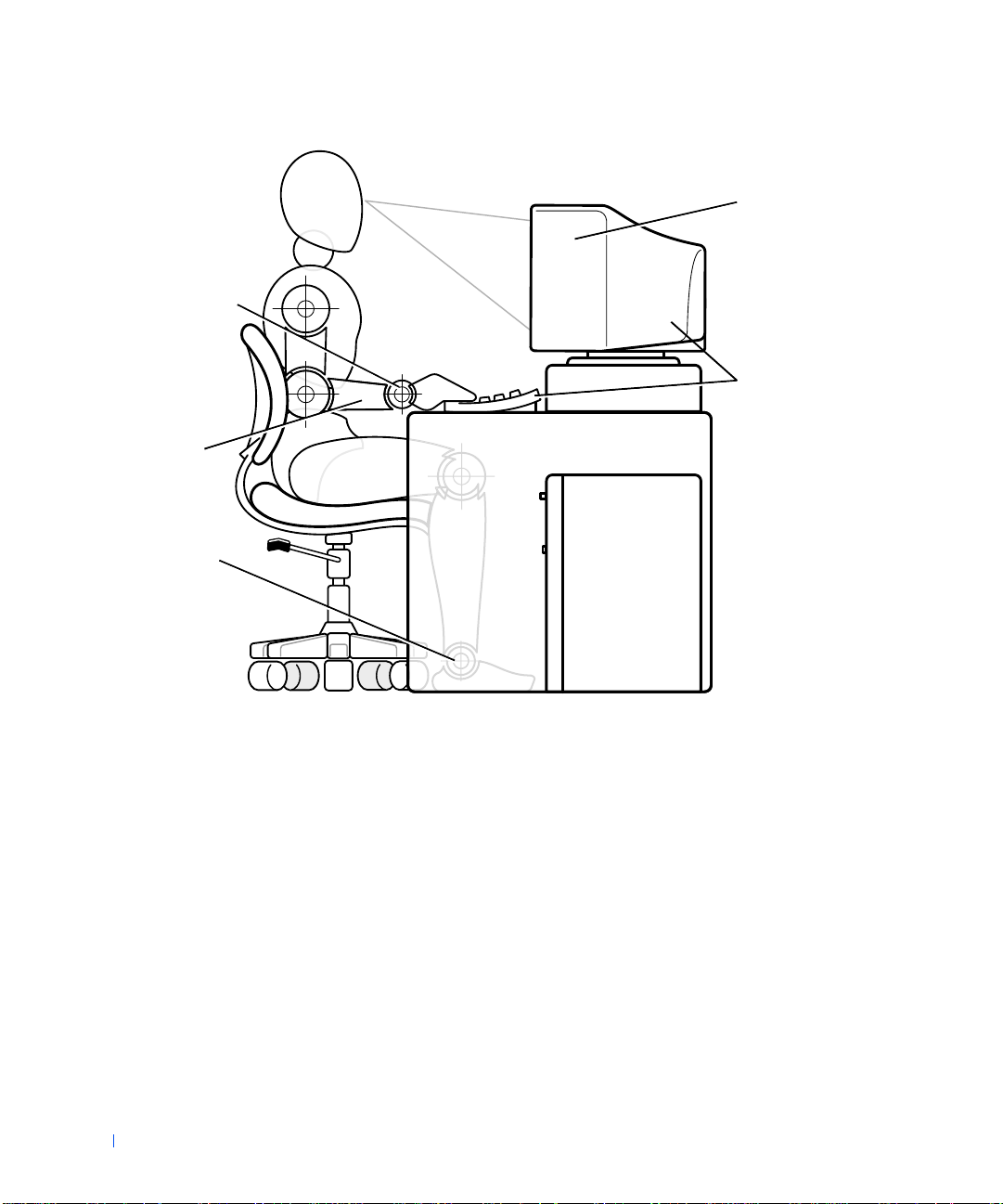
Wrists rel a xed and flat
www.dell.com | support.dell.com
Arms at desk level
Feet flat on the floor
Monitor screen at or
below eye level
Monitor and keyboard
positioned directly in
front of the user
12
Page 13

SECTION 1
About Your Computer
Finding Information and Assistance
Front View of Your Computer
Back View of Your Computer
Inside Your Computer
www.dell.com | support.dell.com
Page 14
Finding Information and Assistance
The following table lists the resources that Dell provides as support tools.
Additional resources may be shipped with your computer system.
Resources and Support Tools
Resource Contents Using the Resour ce
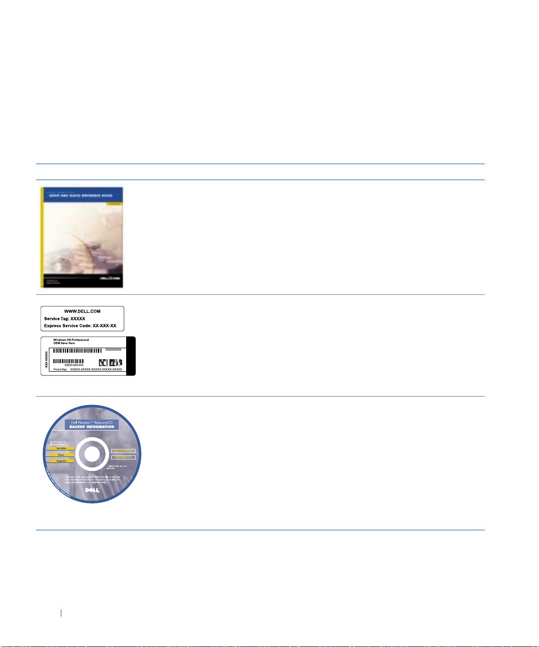
Setup and Quick Reference
Guide
www.dell.com | support.dell.com
• System setup
• Support tools
• Frequently asked questions
• Basic troubleshooting
• Upgrade information
See the Setup and Quick Reference Guide for information
on the following:
• Setting up your compu ter
• Finding and using supp ort resources
• Diagnosing a problem
• Using tools and utilities
Registration and Service
Labels
•Product Key (also called the
Product ID or Certificate of
Authenticity [COA])
• Express Service Code and
Service Tag Number
The labels are located on the
side of your Dell™ computer.
Dell Precision ResourceCD
•Dell Diagnostics
•Drivers
• Utilities
•Computer and device
documentation
You will need the Product Key (or Product ID) number to
complete th e o p er ating system setup.
The Express Service Code and Service Tag Number are
unique identifiers for your Dell computer.
For more information, see the Setup and Quick Reference
Guide.
See the main menu on the ResourceCD that was shipped
with your computer. Use the pull-down menu to make
selections appropriate for your computer . You can perform
the following tasks:
• Diagnose a problem
• Install or reinstall drivers
• Obtain information on your computer and devices
NOTE: User documentation and drivers are already
installed on your computer when shipped from Dell. You
can use this CD to access docume ntation, reinst all drive rs,
or run diagnostic s tools.
14 About Your Computer
Page 15
Resources and Support Tools
Resource Contents Using the Resour ce
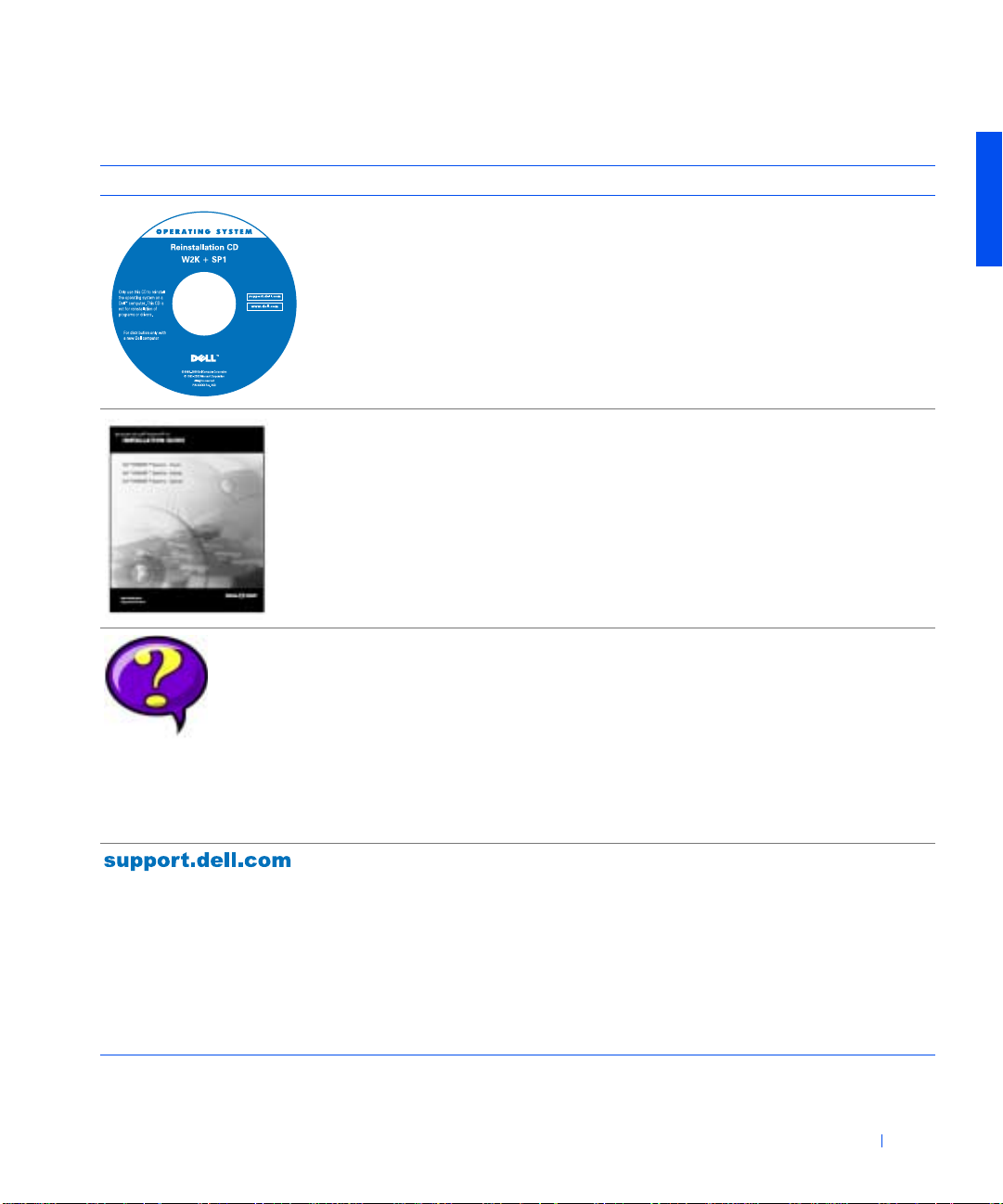
Operating system CD To rei nstall your operatin g system, use the operating
(continued)
system CD that was shipped with your computer.
NOTE: The operating system CD may not include all the
latest drivers for your computer. If you reinstall your
operating system, use the ResourceCD to reinstall drivers
for the devices shipped with your computer.
For more information about reinstalling your operating
system, see the op erating system i nstallation
documentation that was shipped with your computer.
Operating system installati on
guide
User’s guides for your
computer and peripherals
Dell support website
•Ask Dudley
• Dell Knowledge Base
•Dell Documents
•DellTalk
•File downloads
•TechFax
•Vendor links
See the operating system installation guide for
information on reinstalling and configuring your
operating system.
Double-click the User’s Guides icon on your desktop to
access the electronic documentation stored on your hard
drive. Obtai n information o n th e fo llowing:
• Using your computer
• Installing upgrades in your computer
• Installing a nd configuring software on y o ur computer
• Diagnosing a system problem
• Technical specif ications
• Peripheral documentation
Go to http://support.dell.com:
• Get help with general usage, installation, and
troubleshooting questions
• Access documentation about your computer and
devices
• Get the latest versions of the drivers for your computer
• Join online discussions with other Dell customers and
Dell technical professionals
• Explore a list of online links to Dell's primary vendors
About Your Computer 15
Page 16
Resources and Support Tools
Resource Contents Using the Resour ce
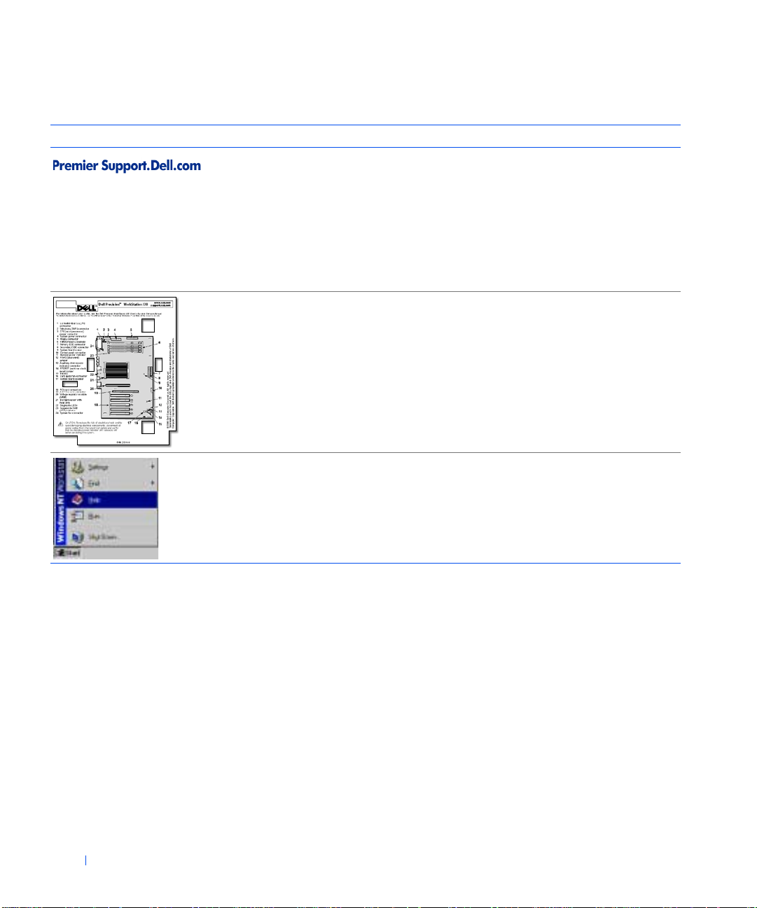
Dell Premier Support website
•Service call status
•Top technical issues by
• Frequently asked questions
• Customized serv ic e ta gs
• System configuration deta il
www.dell.com | support.dell.com
Interior service la bel A service label affixed to the inside of your computer
(continued)
Go to http://premiersupport.dell.com:
The Dell Premier Support website is customized for
corporate, government, and education customers.
product
by product number
cover provides information about working inside your
computer.
Operating system
documentation
16 About Your Computer
Click Start and select Help to obtain in form at io n on your
operating system.
Front View of Your Computer
The following figures show the controls and indicators located on the front
panel of the mini tower and des ktop systems.
Page 17
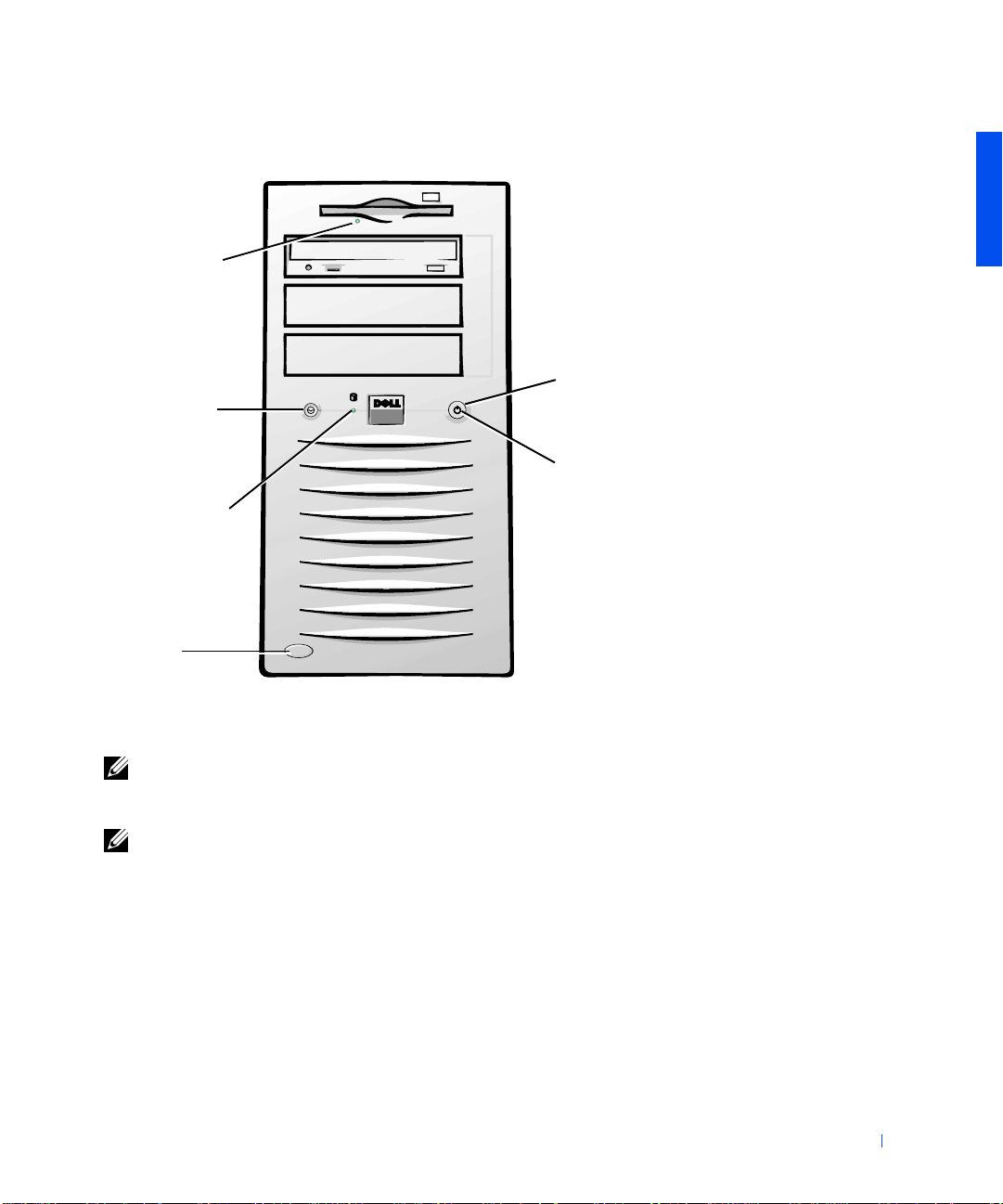
Front View of the Mini Tower Chassis
diskette-drive
access indicator
reset button
hard-drive
access indicator
cover release
button
power button
power indicator
NOTE: Before you remove the cover from the mini tower chassis, you must
first slide the outer padlock ring to the left to unlock the cover release
mechanism. See "Cover Releas e Mechanism (Mini Tower Chassis)."
NOTE: See "Front-Panel Indicators" for a description of indicator codes and
operations.
About Your Computer 17
Page 18
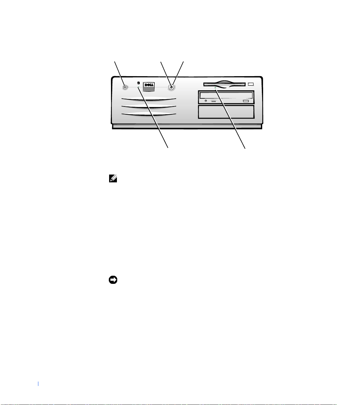
Front View of the Desktop Chassis
reset button
www.dell.com | support.dell.com
power indicator
NOTE: See "Front-Panel Indicators" for a description of indicator codes and
operations.
power button
hard-drive
access indicator
diskette-drive
access indicator
Controls and Indicators
• Reset button — reboots (restarts) the system in a way that reduces
stress on system components. Before you push this button, save and
close all open files and application programs if possible to avoid losing
data. Then perform an orderly shutdown of the operating system.
18 About Your Computer
If your computer is not responding, you can press the reset button to
reboot the system. For more information, see "Recover From a
Program That Is Not Responding" and "Restart a Computer That Is
Not Responding."
NOTICE: If your compute r is not respo nding, t urning off power o r unplugg ing
the power cord should be done only as a last resort. Doing so can cause
problems with system settings and configuration.
• Power button — controls the system's AC input power. See the
following table for power button functions on systems running
Microsoft
®
Windo ws® or WindowsNT®.
Page 19

Power Button Functions
Computer St atus Power Button Func tion
Off Press and rel ease to turn the computer on.
On Press and hold for more than 6 seconds to immediately turn
the computer of f .
NOTE: Use this method only if the computer will not shut
down normally.
On (Windows NT) Press and release to attempt an orderly shutdown.
NOTE: This works only if the Dell System Utilities are
loaded on the computer. Without the utilities, the computer
immediately turns off rather than perf orms an orderly shut
down.
On (Windows 2000) Press and release to put the computer in the sleep state.
NOTE: This works dependi ng on how Windows 2000 is
configured. For more information, see "Power
Management."
Sleep state
(Windows 2000)
Press and release to bring the computer out of the sleep
state. For more information, see "Power Management."
•Power indicator — contains an indicator that illuminates in two colors
and blinks or remains solid to indicate different states.
• Diskette-drive access indicator — lights when the drive is reading data
from, or writing data to, a diskette. Wait until this indicator turns off
before you remove a diskette from the drive.
• Hard-drive access indicator — lights when a hard drive or CD drive is
reading data from, or writing data to, the drive.
• Cover release button — releases the computer cover; located on back
of the mini tower chassis and on the sides of the desktop chassis.
Back View of Your Computer
The following figure shows the connectors and indicators on the back of
your computer for attaching external devices.
About Your Computer 19
Page 20
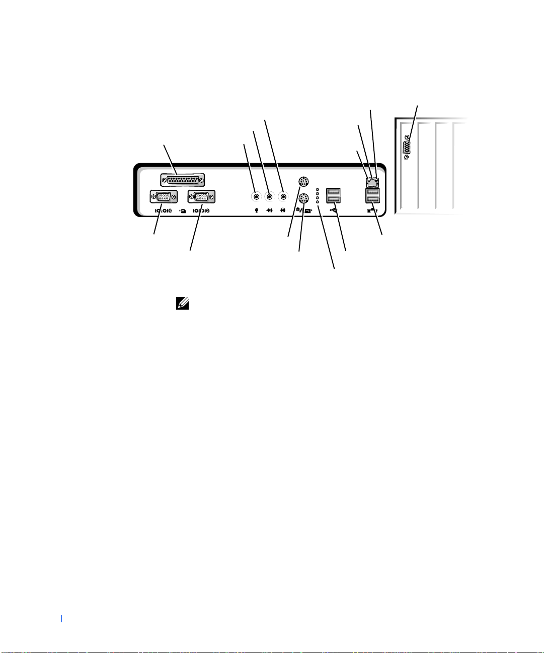
Back-Panel Connectors and Indicators
network activity
line-in jack
line-out/speaker jack
parallel port connector
www.dell.com | support.dell.com
serial port 2 connector
serial port 1 connector
microphone jack
PS/2 mouse connector
PS/2 keyboard connector
NOTE: See "Back-Panel Indicators" for a description of indicator codes and
operations.
NIC connector
network link
integrity indicator
indicator
Port 2 USB connectors (2)
Port 1 USB connectors (2)
diagnostic indicators
video connector
Connecting Devices
When you connect external devices to your computer's back panel, follow
these guidelines:
20 About Your Computer
• Check the documentation that accompanied the device for specific
installation and configuration instructions.
For example, you must connect most devices to a particular
input/output (I/O) port or connector to operate properly . Also , external
devices like a printer usually require you to load device drivers before
they will work.
• When connecting a Universal Serial Bus (USB) mouse or keyboard,
ensure that you connect to one of the Port 1 USB connectors.
• Always attach external devices while your computer is turned off. Then
turn on the computer before turning on any external devices, unless
the documentation for the device specifies otherwise.
Page 21

NOTICE: When you disconnect external devices from the back of the
computer, wait 5 seconds after turning off the computer before you reconnect
any devices to avoid possible damage to the system board.
Serial Port Connectors
Default port designations: COM1 for serial port 1 and COM2 for serial port
2. You can reassign the serial port's design ation in system setup if you add an
expansion card containing a serial port using this designation.
If you set the system’s serial ports to Auto in syst em setup and add an
expansion card containing a serial port configured to a specific designation,
the computer automatically maps (assigns) the in tegrated ports to the
appropriate COM setting as necessary.
Before you add a card with a serial port, ch e ck the docume ntation that
accompanied your software to ensure that the software can be mapped to
the new COM port designation.
Parallel Port Connector
Used to connect printers. Default designation: LPT1.
NOTE: The integrated parallel port is automatically disabled if the system
detects an installed expansion card containing a parallel port configured to the
same address as specified in the Parallel Port option in system setup.
Microphone Jack
Used to attach a standard personal computer microphone. Connect the
audio cable from the microphone to the microphone jack.
Line-Out/Speaker Jack
Used to attach computer speakers. This jack is amplified, so speakers with
integrated amplifiers are not required. Connect the audio cable from the
speakers to this jack.
Line-In Jack
Used to attach record/pla yback devices such a s ca ssette play ers, CD pl ayers,
and VCRs. Connect the line-out cable from any of these devices to the linein jack.
About Your Computer 21
Page 22

PS/2 Mouse Connector
Attach the Personal System/2 (PS/2) mouse cable to the 6-p in mouse
connector on the back panel. If your system uses Microsoft Windows, Dell
installed the necessary mouse drivers on your hard drive.
NOTE: This connector is similar to the keyboard connector. Ensure that you
correctly identify the mouse connector befo re you connect the device.
NOTE: Do not attempt to operate a PS/2 mouse and a USB mouse
simultaneously.
PS/2 Keyboard Connector
www.dell.com | support.dell.com
Attach the PS/2 keyboard cable to the 6-pin keyboard connector on the back
panel.
NOTE: This connector is similar to the mouse connector. Ensure that you
correctly identify the keyboard connector before you connect the device.
USB Connectors
Used to attach USB-compliant devices such as keyboards, mice, printers,
and computer speakers to your system.
NOTE: When connecting a USB mouse or keyboard, ensure that you connect
to one of the Port 1 USB connectors.
NOTE: Do not attempt to operate a PS/2 mouse and a USB mouse
simultaneously.
22 About Your Computer
NOTICE: USB devices do not operate with Microsoft Windows NT.
NIC Connector
The network interface controller (NIC), which includes a Remote W a ke Up
feature, has the following indicators:
• A yellow network activity indicator flashes when the system is
transmitting or receiving network data. (A high volume of network
traffic may make this indicator appear to be in a steady "on" state.)
• A dual-colored network link integrity and speed indicator, which is
green when a good connection exists between a 10-megabit per second
(Mbps) network and the NIC, or is orange when a good connection
exists between a 100-Mbps network and the NIC. When the orange or
green indicator is off, the computer is not detecting a physical
connection to the network.
Page 23

NOTICE: Do not connect a modem cable to the network adapter. Voltage
from telephone communications can damage the network adapter.
Network Cable Requirements
The NIC connector attaches an unshielded twisted pair (UTP) Ethernet
cable to your system. Press one end of the UTP cable into the NIC
connector until the cable snaps securely into place. Connect the other end
to an RJ45 jack wall plate or to an RJ45 port on a UTP concentrator or hub,
depending on your network configuration.
Dell recommends the use of Category 5 wiring and connectors for our
customers’ networks.
Video Connector
Used to attach a video graphics array (VGA)-compatible monitor to your
system.
Inside Your Computer
The following figures show the mini tower and desktop chassis with their
covers removed.
About Your Computer 23
Page 24
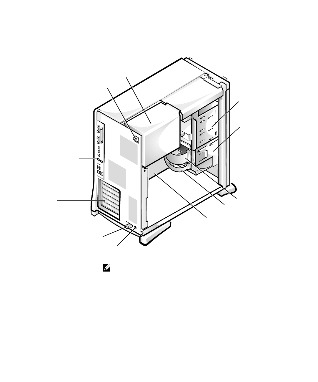
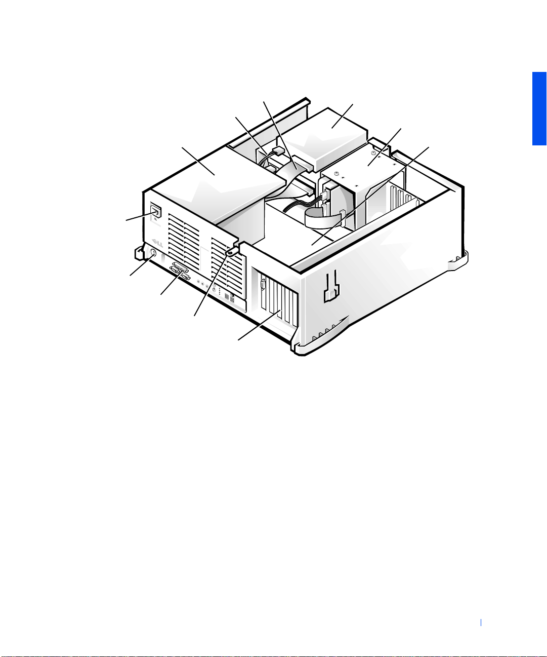
power supply
AC power receptacle
Inside the Mini Tower Chassis
externally accessible
drive bays
www.dell.com | support.dell.com
hard-drive bracket
I/O panel
connectors
expansion-card
slots
drive interface cable
DC power cable
system board
padlock ring
security cable slot
NOTE: Before you remove the cover from the mini tower chas sis, you must
first slide the outer padlock ring to the left to unlock the cover release
mechanism. See "Cover Releas e Mechanism (Mini Tower Chassis)."
24 About Your Computer
Page 25
Inside the Desktop Chassis
AC power
receptacle
security cable slot
I/O panel connectors
power supply
D
padlock ring
expansion-card slots
drive inte rface cable
DC power cable
externally accessible drive bays
hard-drive bracket
system board
System Board Components
The following figure shows the system board and the location of its
principal connectors and components.
About Your Computer 25
Page 26
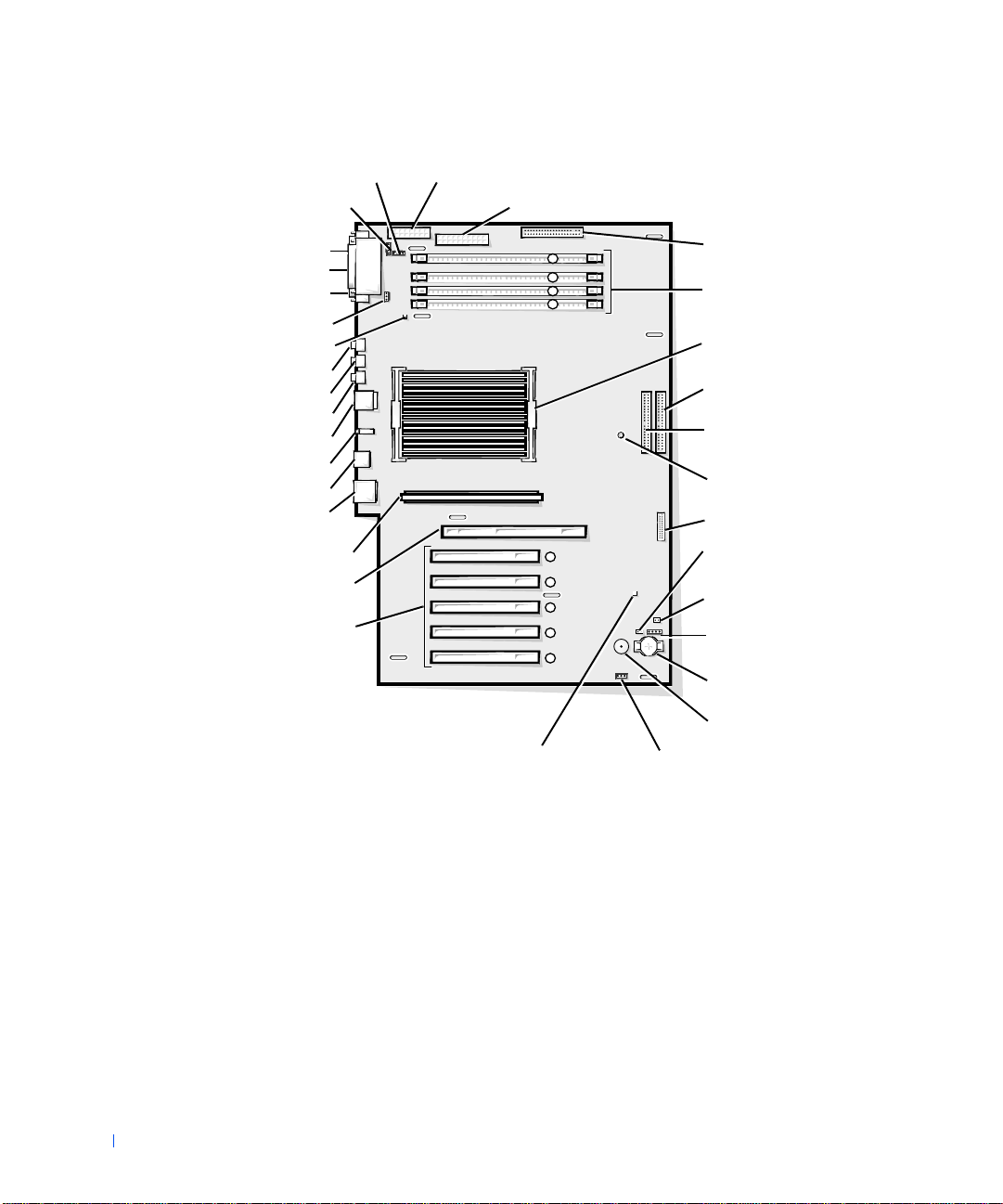
System Board Components
telephony connector
CD audio input connector
serial port 2 connector
parallel port connector
serial port 1 connector
microprocessor fan connector
suspend-to-RAM indicator
microphone connector
line-out/speaker connector
www.dell.com | support.dell.com
line-in connector
PS/2 mouse and keyboard connectors
diagnostic indic ators
Port 1 USB connectors (2)
NIC and Port 2 USB connectors (2)
VRM connector
AGP Pro connector
PCI expansion card connectors (5)
microprocessor power connector
system power connector
3 41 2
345 12
diskette-drive connector
RIMM sockets (4)
microprocessor with
heat sink
primary EIDE connector
secondary EIDE connector
system-board screw hole
control-panel connector
real-time clock reset
(RTCRST) jumper
password jumper
auxiliary hard-drive access
indicator connector
battery socket
26 About Your Computer
standby power indicator
external speaker
I/O fan connector
Page 27

SECTION 2
Advanced Features
System Settings
Manageability
Security
Password Protection
Jumper Settings
Installing and Configur ing Software
TAPI
Power Management
Dell System Utilities
www.dell.com | support.dell.com
Page 28

System Settings
Each time you start your computer, it compares the installed hardware with
the system configuration information stored in nonvolatile random-access
memory (NVRAM). If the system detects a discr epa ncy, it generates an error
message for each incorrect configuration setting.
You can use system settings as follows:
• To set user-selectable options such as date and time or system
password
www.dell.com | support.dell.com
• To set the current configuration information such as the amount of
memory or type of hard drive installed
You can view the current settings at any time. Dell recommends that you
record the information for future reference. If you have a line printer
connected to the parallel port on your computer, you can print the system
setup screens by pressing <Print Screen>.
Before you use system setup, you need to know the kind of diskette drive(s)
and hard drive(s) installed in your computer. If you are unsure of this
information, see the Manufacturing Test Report that came with your
system and is located in the Dell Accessories folder.
Entering System Setup
1 Turn on your system.
2 If your system is already on, restart it.
3 When F2 = Setup appears in the upper-right corner of the screen,
press <F2>.
If you wait too long and your operating system begins to load into memory,
let the system complete the load operation; then restart the system and try
again.
28 Advanced Features
NOTE: To ensure an orderly system shutdown, consult the documentation that
accompanied your operating system.
Page 29

System Setup Screens
Tab
Shift
Tab
The system setup screens display the current configuration information for
your computer. Information on the screen is organized into four areas:
• Title — the box at the top of all screens that lists the computer system
name.
• Computer data — two boxes below the title box that display your
system processor, level 2 (L2) cache, service tag, and the version
number of the basic input/out put sy ste m (BIOS).
• Options — a scrollable box listing options that define the
configuration of your computer, including installed hardware, power
conservation, and security features.
Fields to the right of the option titles contain settings or values. Those
that you can change appear bright on the screen. Those that you
cannot change (because they are set by the computer) appear less
bright. Wh en
<Enter> to access a pop-up menu of additional options.
• Key functions — a line of boxes across the bottom of all screens that
lists keys and their functions within system setup.
• Help — press <F1> for information in the currently highlighted
option.
<Enter> appears to the right of an opti on title, press
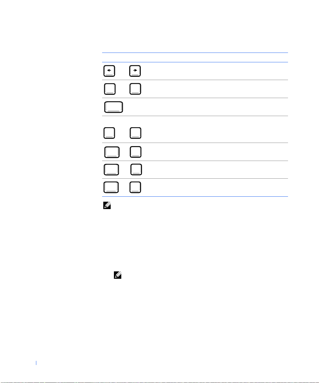
System Setup Navigation Keys
The following table lists the keys you use to view or change information in
system setup and to exit setup.
System Setup Navigation Keys
Keys Actio n
Tab
Shift
or
Tab
or
Moves to the next field.
Moves to the previous field.
Advanced Features 29
Page 30
System Setup Navigation Keys
Page
Up
Page
Down
Enter
+
Alt
Alt
Alt
Keys Action
or
Cycles through the op tions in a field. In many fields, you
can also type the appropriate value.
(continued)
Page
Down
Enter
Page
or
Up
Scrolls through help information.
Enters the selected field's pop-up options menu.
spacebar or In the selected field's pop-up options menu, cycles through
www.dell.com | support.dell.com
_
or
+
Alt
Alt
Alt
X
B
D
the options in a field.
Exits system setup without rebooting the system and
returns the system to the boot ro utine.
Exits system setup and reboots the system, implementing
any changes you have made.
Resets the selected option to its default setting.
NOTE: F or most of the options, any changes you make are recorded but do not
take effect until the next time you boot the computer. For a few options (as
noted in the help area), the changes take effect immediately.
Changing the Boot Sequence
The boot sequence allows you to specify the order of the devices from which
the system attempts to boot.
30 Advanced Features
1 Press <Ente r> to access the Boot Sequence option's pop-up menu.
NOTE: Write down your current boot sequence in case you want to
restore it.
Press the up- and down-arrow keys to move through the list of devices.
2
3 Press the spacebar to enable or disable a device (enabled devices
appear with a check mark).
4 Press plus (+) or minus (–) to move a selected device up or down the
list.
Page 31

Option settings:
• Diskette Drive A: — The system attempts to boot from the dis kette
drive. If the system finds a diskette in the drive that is not bootable, an
error message appears. If no diskette is in the drive, the system
attempts to boot from the next device in the list.
• Hard Drive — The system attempts to boot from the primary hard
drive. If the system does not find an operating system on the drive, it
attempts to boot from the next device in the list.
• CD Drive — The system attempts to boot f rom the CD drive. If the
system does not find a CD in the drive or if there is not an operating
system on the CD, the system attempts to boot from the next device
in the list.
• MBA — The system prompts you to press <Ctrl><Alt><b> at the
Dell logo screen during b oot. A me nu ap pears t hat allows you to select
a method for booting from a network server. If a boot routine is not
available from the network server, the system attempts to boot from
the next device in the list.
Network Operations
For proper network operations, several options in system setup must be
configured properly:
• Network interface controller
• Boot sequence
• Remote wake up
For information on the relationship of the various option settings, see
"Network Configurations."
Network Interface Controller
This option, under the Integrated Devices menu, enables or disables the
integrated network adapter. This field also allows you to enable managed
boot agent (MBA) support.
Option settings:
• On — The integr ated network adapter is enabled.
Advanced Features 31
Page 32

• On w/ MBA — The integrated network adapter is enabled with MBA
support.
• Off — The integrated network adapter is disabled.
NOTE: You must restar t the computer before Network Interface Controller
option settings will take effect.
Boot Sequence
The Boot Sequence MBA option setting allows yo u to s pe c ify a m e tho d f o r
booting from a network server.
www.dell.com | support.dell.com
Remote Wake Up
Remote Wake Up provides the ability either to remotely wake a computer
from a low-power sleep state or to remotely start up a computer that is
turned off but connected to a power source.
Option settings:
• On — The computer will start up when the appropriate signal is
received by the network adapter (Wake-on Lan [WOL]), or modem
(Wake-on Ring [WOR]).
• On w/ Boot to NIC — When the network adapter or modem receives
the appropriate signal, the computer attempts to boot from a network
server. If a boot routine is not available from the network server, the
computer attempts to boot from the devices specified in the Boot
Sequence.
• Off — The computer will not start up remotely.
Network Configurations
The system setup options for network operations work together for
particular functions. The following table describes the relationship of the
various option settings:
32 Advanced Features
Page 33

Network Option Settings
Network Interface
Controller
Off MBA is not available Not available • The computer attempts to boot from the devices
On MBA is not available Available • The computer attempts to boot from the devices
On w/ MBA MBA is set as firs t
NOTE: You must restart the computer before Network Interface Controller
option settings will take effect.
Boot Sequen ce Remote Wake Up Function
specified in the Boot Sequence.
• The computer cannot be remotely started.
specified in the Boot Sequence.
• The computer can be remotely started by WOL
and/or WOR.
Available • The computer prompt s you to press
boot device
<Ctrl><Alt><b> during start-up, allowing
you to select a network boot method.
• The computer can be remotely started by WOL
and/or WOR.
Integrat ed D evices
You computer has several integrated devices. For these devices to be
accessible to the operating system, the corresponding options in system
setup must be configured properly.
To enable or disable an integrated device, enter system setup, select
Integrated Devices, and change the setting for the appropriate device to On
or Off:
• Sound
• PS/2 mouse
• Universal Serial Bus (USB)
Advanced Features 33
Page 34

Manageability
The following systems management applications are optional and can be
included on your computer when you order it. You can also download the
applications from the Dell support website and install them on your
computer. See "Downloading Systems Management Utilities" for more
information.
•Dell OpenManage™ IT Assistant
• Dell OpenManage Client Instrumentation
www.dell.com | support.dell.com
Dell OpenManage IT Assistant
Dell OpenManage IT Assistant is the premier Dell™ systems management
application for configuring, managing, and monitoring computers and other
devices on a corporate network. IT Assistant employs the latest remote
management technology to provide asset management, configuration
management, event (alert) management, and security management for
systems equipped with industry-standard management software. Software
of this type is called system management instrumentation.
IT Assistant supports instrumentation that conforms to the following
industry standards:
• Simple Network Management Protocol (SNMP)
• Desktop Management Interface (DMI)
• Common Information Model (CIM)
The instrumentation available for your computer is Dell OpenManage
Client Instrumentation, which is based on DMI and CIM. For more
information on IT Assistant, see the Dell OpenManage IT As sistant User’s
Guide available on the Dell support
Management Utilities" for more information.
website. See "Downloading Systems
Dell OpenManage Client Instrumentation
Dell OpenManage Client Instrumentation is software that enables remote
management application programs such as IT Assistant to do the following:
34 Advanced Features
Page 35

• Access information about your computer , such as how many processors
it has and what operating system it is running
• Monitor the status of your computer, such as listening for thermal
alerts from temperature probes or hard drive failure alerts from storage
devices
• Change the state of your computer, such as updating its BIOS or
shutting it down remotely
Dell OpenManage Client Instrumentation can be installed on your
computer, which, when set up on a network with IT Assistant, is called a
managed system. For mo re information about Dell OpenManage Client
Instrumentation, see the Dell OpenManage Client Instrumentation User’s
Guide available on the Dell suppo r t website. See "Downloading Systems
Management Utilities" for more information.
Downloading S y s te m s Management Ut il ities
The systems management utilities are available for download from the Dell
support website. See "Finding Information and Assistance" for more
information.
1 Go to http://support.dell.com.
If this is your first time to use this website, complete the one-time
registration.
2 Click Downloads for Your Dell.
3 Enter the Service Tag Numb er for your computer or select the
appropriate Dell system.
4 Select the appropriate operating system and language for your
computer.
5 Select Systems Management for the download category.
6 Click Go.
7 Follow the instructions on the screen to download and install the
utilities.
Advanced Features 35
Page 36

Security
The computer provides the following methods of phys i c ally securing the
chassis:
• Chassis intrusion detection
• Security cable slot and padlock ring
Chassis Intrusion Detection
The chassis intrusion monitor can detect whether the chassis is opened.
The Chassis Intrusion option in syst e m setup displays the status of the
www.dell.com | support.dell.com
monitor.
1 Enter system setup.
2 Press the down-arrow key to move to the System Security option.
3 Press <Ente r> to access the System Security option's pop-up menu.
4 Press the down-arrow key to move to the Chassis Intrusion option.
5 Press the spacebar to select an option setting.
Option settings:
• Enabled (the default) — When the computer cover is removed with
this setting, a DMI event is generated, the setting changes to
Detected, and the following message appears during the boot routine
at the next system start-up:
36 Advanced Features
Alert! Cover was previously removed.
To reset the Detected setting, enter system setup during the system's
power-on self-test (POST). In the Chassis Intrusion option, press the
left- or right-arrow key to select Reset, and then choose Enabled,
Enabled-Silent, or Disabled.
• Enabled-Silent — When the computer cover is removed with this
setting, a D MI eve nt is ge nerate d and the se tting c hanges t o Detected,
but the alert message does not appear during the boo t sequence at the
next system start-up.
• Disabled — No intrusion monitoring occurs and no messages appear.
Page 37

NOTE: When the setup password is enabled, you must know the setup
password before you can reset the Chas sis Intrusion option.
Security Cable Slot and Pad lock Ring
These features allow you to attach commercially available antitheft devices.
See "Security Features (Mini Tower Chassis)" and "Security Features
(Desktop Chassis)." To prevent unauthorized removal of your computer,
loop the galvanized security cable around an immovable object, insert the
attached locking device into the security cable slot on the back of your
computer, and lock the device with the key provided.
NOTE: Before you purchase an antitheft device, ensure that it works with the
cable slot on your computer.
NOTE: Before you remove the cover from the mini tower chassis, you must
first slide the outer padlock ring to the left to unlock the cover release
mechanism. See "Cover Releas e Mechanism (Mini Tower Chassis)."
Advanced Features 37
Page 38

Security Features (Mini Tower Chassis)
www.dell.com | support.dell.com
security cable slot
padlock ring
38 Advanced Features
Page 39

Security Features (Desktop Chassis)
D
security cable slot
padlock ring
Password Protection
The computer provides the following types of password protection:
•System password
•Setup password
System Password
System passwords allow only those who know the password to have full use
of the system. Your Dell system does not have the system password feature
enabled when you receive it.
NOTICE: Although passwords provide security for the data on your system,
they are not foolproof. If your data requires more security, it is your
responsibility to ob ta in and use additional forms of protection, such as data
encryption programs.
NOTICE: If you leave your system running and unattended without having a
system password assigned, or if you leave your computer unl ocked so that
someone can disable the password by changing a jumper setting, anyone can
access the data stored on your hard drive.
System Password settings in system setup:
Advanced Features 39
Page 40

NOTE: You cannot change or enter a new system password if either of these
options is displayed.
• Enabled — a system password is assigned
• Disabled — system password feature is disabled by a jumper setting on
the system board
NOTE: You can only assign a system password when System Password is set to
Not Enabled.
• Not Enabled — no system password is assigned and the password
jumper on the system board is in the enabled position (its default)
www.dell.com | support.dell.com
Assigning a System Password
1 Verify that Password Status is set to Unlocked.
2 Highlight System Password and then press the left- or right-arrow key.
The option heading changes to Enter Password, followed by an empty
32-character field in square brackets.
3 Type your new system password.
You can use up to 32 characters.
As you press each character key (or the spacebar for a blank space), a
placeholder appears in the field. The password assignment operation
recognizes keys by their location on the keyboard, without
distinguishing between lowercase and uppercase characters. For
example, if you have an M in your password, the system recognizes
either M or m as correct.
Certain key combinations are not valid. If you enter one of these
combinations, the speaker emits a beep.
To erase a character when entering your password, press <Backspace>
or the left-arrow key.
NOTE: To escape from the field without assigning a system password,
press <Tab> or the <Shift><Tab> combination to move to another
field, or press <Esc> at any time before completing step 5.
40 Advanced Features
4 Press <Ente r> .
If the new system password is less than 32 characters, the whole field
fills with placeholders. Then the option heading changes to Verify
Password, followed by another empty 32-character field in s qua re
brackets.
Page 41

5 To confirm your password, type it a second time and press <Enter>.
The password setting changes to Enabled. Your system password is
now set; you can exit system setup and begin using your system.
Password protection takes effect when you reboot the system by
pressing the reset button or by turning the system off and then on
again.
Using Your System Password
When you turn on your system or press the reset button, or when you
reboot the system by pressing the <Ctrl><A lt ><Del> combination, the
following prompt appears on the sc reen wh en Password Status is set to
Unlocked:
Type in the password and
- press <ENTER> to leave password security enabled.
- press <CTRL><ENTER> to disable password security.
Enter password:
If Password Status is set to Locked, the following prompt appears:
Type the password and press <Enter>.
NOTE: If you have assigned a setup password, the system accepts your setup
password as an alter nate system password.
If you enter a wrong or incomplete system password, the following message
appears on the screen:
** Incorrect password. **
Enter password:
If you again enter an incorrect or incomplete system password, the same
message appears on the screen. The third and subsequent times you enter
an incorrect or incomplete system password, the system displays the
following message:
** Incorrect password. **
Number of unsuccessful password attempts: 3
System halted! Must power down.
Even after your system is turned off and on, the previous message is
displayed each time an incorrect or incomplete system password is entered.
Advanced Features 41
Page 42

NOTE: To further protect your system from unauthorized changes, you can use
the Password Status system setup option in conjunction with the System
Password and Setup Password options.
Deleting or Changing an Existing System Password
1 Enter system setup, and verify that Password Status is set to Unlocked.
2 Reboot your system to force it to prompt you for a system password.
3 When prompted, type the system password.
4 Press <Ctrl><Enter> to disable the existing system password,
instead of pressing <Enter> to continue with the normal operation of
www.dell.com | support.dell.com
your system.
5 Confirm that Not Enabled is displayed for the System Password
option.
If Not Enabled appears in the System Password option, the system
password has been deleted. If you want to assign a new password,
continue to step 6. If Not Enabled is not displayed for the System
Password option, press <Alt><B> to reboot the system, and then
repeat steps 3 through 5.
6 To assign a new password, follow the p rocedure in "Assigning a System
Password."
42 Advanced Features
Setup Password
Setup passwords allow only those who know the passwor d to have full use of
system setup. Your Dell system does not have the setup password feature
enabled when you receive it.
Setup Password options in system setup:
• Enabled — does not allow assignment of setup passwords; users must
enter a setup password to make changes to system setup
• Not Enabled — allows assignment of setup passwords; password
feature is enabled but no password is assigned
Assigning a Setup Password
1 Enter system setup, and verify that Setup Password is set to Not
Enabled.
Page 43

2 Highlight Setup Password and press the left- or right-arrow key.
The system prompts you to enter and verify the password. If a
character is illegal for password use, the system emits a beep.
3 Type in and then verify the password.
After you verify the password, the Setup Password setting changes to
Enabled. The next time you attempt to enter system setup, the system
prompts you for the setup password.
NOTE: The setup password can be the same as the system password.
NOTE: If the two passwords are different, the setup password can be used as
an alternate system password. However, the system password cannot be used in
place of the setup password.
A change to Setup Password becomes effective immediately (rebooting the
system is not required).
Operating Your System With a Setup Password Enabled
When you start system setup, the Setup Password option is highlighted,
prompting you to type the password.
If you do not enter the correct password, the system lets you view, but not
modify, system setup options.
NOTE: To further protect your system from unauthorized changes, you can use
the Password Status system setup option in conjunction with the System
Password and Setup Password options .
Deleting or Changing an Existing Setup Password
To change an existing setup password, you must know the setup password.
1 Enter system setup.
2 If you have already assigned a setup password, type it at the prompt.
3 Highlight Setup Password and press the left- or right-arrow key to
delete the existing setup password.
The setting changes to Not Enabled.
4 If you want to assign a new setup password, perform the steps in
"Assigning a Setup Password."
Advanced Features 43
Page 44

Disabling a Forgotten Password
NOTICE: This process erases both the system and setup passwords.
CAUTION: Before you perform this procedure, see "Safety First—
For You and Yo ur Com puter."
Turn off the computer and peripherals, disconnect them from t hei r
1
electrical outlets, wait at least 5 seconds, and then remove the
computer cover.
2 Remove the jumper plug from the PSWD jumper to disabl e the
password feature.
www.dell.com | support.dell.com
See "Jumper Settings" to locate the password jumper (labeled
"PSWD") on the system board.
3 Replace the computer cover.
4 Reconnect your computer and peripherals to an electrical outlet, and
then turn them on.
This erases the existing password(s).
Proceed to step 5 if you want to assign a new password.
NOTE: Before you assign a new system and/or setup password, you must
replace the PSWD jumper plug to reen able the password feature.
Remove the computer cover.
5
6 Replace the PSWD jumper plug.
7 Replace the computer cover and reconnect the computer and
peripherals to an electrical outlet and turn them on.
Booting your system with the PSWD jumper installed reenables the
password feature. When you enter system setup, both password
options appear as Not Enabled, meaning that the password feature is
enabled but that no password is assigned.
8 Assign a new system and/or setup password.
44 Advanced Features
Jumper Settings
The following figure shows the location of the jumpers on the system board.
Page 45

System Board Jumpers
PSWD
RTCRST
NOTICE: Ensure that your system is turned off before you change a jumper
setting. Otherwise, damage to your system or unpredictable results may occur.
To change a jumper setting, pull the plug off its pin(s) and carefully fit it
down onto the pin(s) indicated.
The following table lists the system board jumpers and their settings.
System-Board Jumper Settings
Jumper Setting Description
PSWD (default) Password features are enabled.
Password features are disabled.
RTCRST Real-time clock reset. Can be used for
troubleshooting. See "Reset Corrupted BIOS
Settings."
jumpered unjumpered
Advanced Features 45
Page 46

Installing and Configuring Software
See "Resources and Support Tools" for a list of software resources available
to you from Dell, including drivers, utilities, documentation, and operating
system backups. Before installing software that was not provided with your
Dell computer, check the software for viruses with virus-scanning software.
Viruses can quickly use all available system memory , damage or destroy data
stored on the hard drive, and permanently affect the performance of the
programs they infect. Several commercial virus-scanning programs are
available for purchase, and many websites distribute virus-scanning
programs that you can download.
www.dell.com | support.dell.com
Before you install a program, read its documentation to learn how the
program works, what hardware it requires, and what its defaults are. A
program usually includes installation instructions in its accompanying
documentation and a software installation routine on its program
diskette(s) or CD(s).
The software installation routine assists you in transferring the appropriate
program files to your computer's hard drive. Installation instructions may
provide details about how to configure your operating system to successfully
run the program. Always read the installation instructions before running a
program's installation routine.
When you run the installation routine, be prepared to respond to prompts
for information about how your computer's operating system is configured,
what type of computer you have, and what peripherals are connected to
your computer.
NOTE: If you experience any problems while installing or operating your
software, see "Software Problems."
TAPI
The Telephony Application Programming Interface (T API) enables
Windows-based applications to operate with a wide variety of telephony
devices, including voice, data, fax, video, and so forth. TAPI applications
require a TAPI service provider (TSP), which is a software driv er that allows
TAPI applications to communicate with different types of TAPI hardware.
46 Advanced Features
Page 47

Microsoft® Windows® and Windows NT® provide a TSP called
Unimodem, which is a "universal" modem service provider that supports a
wide range of commonly used modems. For more information on
Unimodem, see your Windows documentation. When using a TAPI device
other than a modem, such as a Private Branch Exchange (PBX) or a voice
processing card, you will need a TSP provided by the manufacturer of the
device.
The TAPI system-board connector uses a 4-pin cable to interface your
internal TAPI-compliant expansion card with the audio system in your
computer. To locate the TAPI system-board connector, see "System Board
Components." Your system supports TAPI-compliant cards using the
standard TAPI connector. For example, you can connect your modem to the
TA PI connector and then use your audio speakers and microphone as a
speakerphone. The microphone carries your voice into the computer and
then through the TAPI system board connector to your modem card. The
caller’s voice enter s through the modem card to the TAPI system board
connector and then out to the speakers. You can also use this configuration
to record and play sound files over the phone.
Installing a TAPI Device
CAUTION: Before you perform this procedure, see "Safety First—
For You and Yo ur Com puter."
1
Turn off the computer and peripherals, disconnect them from their
electrical outlets, wait at least 5 seconds, and then remove the
computer cover.
2 Install the TAPI-compliant expansion card.
See the manufacturer’s documentation for more information.
3 Rotate the power supply away from the system board.
4 Connect the 4-pin TAPI cable to the TAPI system-board connector.
To locat e the TAPI connector on the system board, see "System Board
Components."
5 Connect the 4-pin TAPI cable to the TAPI expansion-card connector.
To locate the TAPI connector on the expansion card, see the
manufacturer’s documentation.
Advanced Features 47
Page 48

6 Rotate the power supply back into position, making sure that the
securing tab snaps into place.
7 Replace the computer cover.
8 Reconnect your computer and peripherals to an electrical outlet, and
then turn them on.
9 Install the appropriate TSP for the TAPI device.
See the manufacturer’s documentation and your Windows
documentation for more information.
www.dell.com | support.dell.com
Installing a TAPI Sound Card
You can install a TAPI-compliant sound card that has a standard TAPI
connector. For example, you can connect your modem to the TAPI sound
card connector and then use the audio capabilities as a speakerphone.
CAUTION: Before you perform this procedure, see "Safety First—
For You and Yo ur Com puter."
Turn off the computer and peripherals, disconnect them from t hei r
1
electrical outlets, wait at least 5 seconds, and then remove the
computer cover.
2 Install the TAPI-compliant sound card.
See the manufacturer’s documentation for more information.
3 Enter system setup, click Integrated Devices, and change the setting
for Sound to Off.
4 Connect external audio devices to the sound card’s connectors. Do not
connect external audio devices to the microphone, line-out, or line-in
connectors on the system back panel (see "Back-Panel Connectors and
Indicators").
5 Connect the 4-pin TAPI cable to the TAPI sound-card connector.
To locate the TAPI connector on the sound card, see the
manufacturer’s documentation.
6 Connect the 4-pin TAPI cable to the TAPI expansion-card connector.
48 Advanced Features
To locate the TAPI connector on the expansion card, see the
manufacturer’s documentation.
Page 49

7 Replace the computer cover.
8 Reconnect your computer and peripherals to an electrical outlet, and
then turn them on.
9 Install the appropriate TSP for the TAPI devices.
See the manufacturer’s documentation and your Windows
documentation for more information.
Power Management
Your computer can be set to use less power when you are not working. You
control the power usage through the operating system (OS) installed on
your computer and certain option settings in system setup. These periods of
reduced power are called "sleep states":
• Standby. In this sleep state, power to most components is reduced or
turned off. However, system memory remains active.
This state is not supported by Windows NT 4.0.
NOTE: This state can be controlled through the Suspend Mode option in
system setup.
• Hibernate. This sleep state reduces power consumption to a minimum
by writing all data in system memory to a hard drive and then
removing system power. Waking up from this state restarts the
computer, and the memory contents are restored. Operation then
resumes where the system left off when it entered the hibernation
state.
This state is supported by Windows 2000 only.
NOTE: All components installed in the computer must support this
feature and have the appropriate drivers loaded to enter hibernation. For
more information, see th e manufacturer’s documentation for each
component.
Advanced Features 49
Page 50

• Shutdown. This sleep state removes all power from the system except
a small auxiliary amount. As long as the computer remains connected
to an electrical outlet, it can be automatically or remotely started. For
example, the Auto Power On feature allows the computer to
automatically start at a time you specify in system setup. Also, your
network administrator can remotely start your computer using a power
management event (PME) such as access through a network
connection (Wakeup On LAN).
The following table lists the sleep states available for each operating system
as well as the methods you can use to "wake up" from each state.
www.dell.com | support.dell.com
Power Management
Sleep State Wake-Up Methods
Windows 2000 Windows NT 4.0
Standby • Press the power button
• Auto power on
•PME
• Move or click the PS/2 mouse
• Move or click the USB mouse
• Type on the PS/2 keyboard
• Type on the USB keyboard
• USB device activity
Hibernate • Press the power button
• Auto power on
•PME
Shutdown • Press the power button
• Auto power on
•PME
NOTE: For more information on power ma nagement, see your operating
system documentation.
Not supported
Not supported
• Press the power button
• Auto power on
•PME
50 Advanced Features
Page 51

Dell System Utilities
If you received your computer from Dell with the operating system
preinstalled, Dell also installed the system utilities. If you are reinstalling
the operating system, you also need to reinstall the system utilities on your
computer. The utilities are available on the Dell ResourceCD and from the
Dell support we bsite. See "Finding Information and Assistance" for more
information.
AutoShutdown
The Dell AutoShutdown utility lets you perform an orderly system
shutdown and then turn off your computer after successfully closing the
OS. All this is done wit h a single touch of the power button. Additionally,
AutoShutdown works with some application programs to prompt you to
save your files before the computer turns off (such as Microsoft Word and
Excel).
NOTICE: The AutoShutdown uti lity is intend ed only for us e in Windows NT ®.
The functions of this utility are incorporated into Windows® 2000.
To verify whether the utility is installed and running under Windows NT,
open the Control Panel and double-click Services. If the AutoShutdown
service is installed and running, it is listed with the status Started.
Asset Tag
The Dell Asset Tag utility is an MS-DOS® program for displaying and
setting the system asset tag and system owner tag.
Auto Power On
The Dell Auto Power On utility is an MS-DOS program that can be used in
a batch file to determine how the system was turned on (by the power
button or by the Auto Power On option in system setup) or to turn off the
system fro m DOS.
NOTICE: The Auto Power On utility is intended only for use in MS-DOS.
Turning off the computer by using the autopwr.com utility in Windows NT can
cause loss of data.
Advanced Features 51
Page 52

www.dell.com | support.dell.com
52 Advanced Features
Page 53

SECTION 3
Installing Upgrades
Computer Cover
Interior Service Label
Power Supply
Front Panel (M in i T o wer Chassis Only)
System Memory
Disk Drives and Media
AGP Card Brace (Mini Tower Chassis Only)
Expansion Cards
Microprocessor
System Battery
www.dell.com | support.dell.com
Page 54

Computer Cover
Removing the Computer Cover
CAUTION: Before you perform this procedure, see "Safety First—
For You and Yo ur Com puter."
Turn off the computer and peripherals, and disconnect them from
1
their electrical outlets.
2 If installed, remove the padlock from the padlock ring on the back
panel.
www.dell.com | support.dell.com
3 Remove the computer cover.
If your computer is a mini tower chassis, perform the following steps:
a Face the back of the computer and slide the outer padlock ring to
the left to unlock the cover release mechanism (see the following
figure).
54 Installing Upgrades
Page 55

Cover Release Mechanism (Mini Tower Chassis)
b Press the cover release button located at the bottom-left cor n er of
the front panel (see the following figure).
c Rotate the bottom of the cover ou tward, away from the chassis.
Installing Upgrades 55
Page 56

Removing the Cover (Mini Tower Chassis)
www.dell.com | support.dell.com
56 Installing Upgrades
cover release button
d Lift the cover away from the chassis.
e Turn the computer on its right side before you begin working
inside the chassis.
If your computer is a desktop chassis, perform the following steps:
a Press the two cover release buttons located on the left and right
sides of the cover (see the following figure).
b Rotate the back of the cover upward, away from the chassis.
Page 57

Removing the Cover (Desktop Chassis)
padlock ring
cover release butto ns (2)
D
c Lift the cover away from the chassis.
Replacing the Computer Cover
1 Check all cable connections and fold cables out of the way so that they
do not catch on the computer cover. Ensure that cables are not routed
over the drive cage—they will prevent the cover from closing properly.
2 Ensure that no tools or extra parts (including scre ws) ar e left inside the
computer chassis.
3 Replace the computer cover.
If your computer is a mini tower chassis, perform the following steps:
a Hold the cover at a slight angle as shown in the following figure.
While aligning the top of the cover wi th the top of the chassis,
insert the three hooks on the cover into the three recessed slots on
the computer chassis.
b Rotate the cover downward toward the bottom of the chassis.
With both hands, press against the bottom edge of the cover to
Installing Upgrades 57
Page 58

ensure that the securing hooks at the bottom of the cover click
into place.
Replacing the Cover (Mini Tower Chassis)
hook
www.dell.com | support.dell.com
recessed slot
58 Installing Upgrades
c Slide the two parts of the padlock ring together to lock the cover
release mechanism.
If your computer is a desktop chassis, perform the following steps:
a Hold the cover at a slight angle as shown in the following figure.
b Fit the three cover hooks into the recessed slots at the bottom of
chassis. (It might be helpful to look down into the chassis to verify
that the hooks are in place.)
Page 59

c Rotate the cover downw ard and into pos iti on. Ens ur e tha t th e two
cover release buttons click into place.
Replacing the Cover (Desktop Chassis)
recessed
slots (3)
cover release buttons (2)
Interior Service Label
A service label affixed to the inside of your computer cover indicates the
location of system board components and connectors.
hooks (3)
Installing Upgrades 59
Page 60

Interior Service Label (Mini Tower Chassis)
interior view of
left side cover
www.dell.com | support.dell.com
service
label
Interior Service Label (Desktop Chassis)
interior view of
top cover
service
label
60 Installing Upgrades
Page 61

Power Supply
To access some of the comp onents on the system board, you may need to
rotate the system pow er supply out of the way.
CAUTION: Before you perform this procedure, see "Safety First—
For You and Yo ur Com puter."
Turn off the computer and peripherals, disconnect them from their
1
electrical outlets, wait at least 5 seconds, and then remove the
computer cover.
2 Ensure that the AC power cable is disconnected from the AC power
receptacle on the bac k of the power supply. See "Rotating the Power
Supply (Mini Tower Chassis)" or "Rotating the Power Supply
(Desktop Chassis)."
3 Free the power supply from the secur ing tab by pressing the tab
labeled "RELEASE." Then rotate the power supply upward until it
locks in its extended position.
Installing Upgrades 61
Page 62
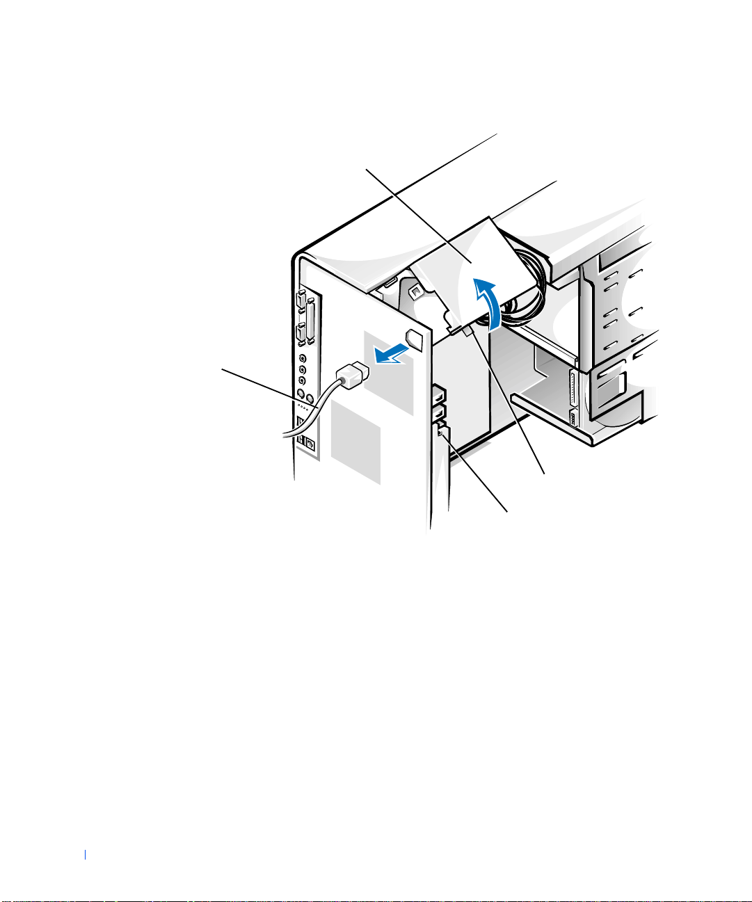
Rotating the Power Supply (Mini Tower Chassis)
power supply
www.dell.com | support.dell.com
AC power
cable
securing tab
62 Installing Upgrades
release latch
Page 63

Rotating the Power Supply (Desktop Chassis)
securing tab
power supply
AC power
cable
release latch
When you have finished accessing components on the system board, rotate
the power supply back to its original position until the release latch snaps
into the securing tab.
Front Panel (Mini Tower Chassis Only)
CAUTION: Before you perform this procedure, see "Safety First—
For You and Yo ur Com puter."
To remove the front panel, you first must remove the computer cover . With
the cover removed, release the front panel by pressing the green front-panel
release button marked with the icon (see the following figure).
Installing Upgrades 63
Page 64

Removing the Front Panel (Mini Tower Chassis)
front-panel release
button
front-panel
latches (2)
front-panel tabs (2)
www.dell.com | support.dell.com
retaining hooks (2)
While pressing the front-panel release button, rotate the top of the panel
outward, away from the chassis. Lift the panel away from the chassis.
To replace the front panel, fit the two front-panel retaining hooks into the
recessed slots at the bottom of the chassis. See "Removing the Front Pane l
(Mini Tower Chassis)." Then rotate the top of the panel toward the chassis
until the front-panel latches snap i n to the tabs on the front panel.
64 Installing Upgrades
Page 65

System Memory
Your computer supports Rambus dynamic random-access memory
(RDRAM) Rambus in-line memory modules (RIMMs) in 64-, 128-, 256-,
and 512-megabyte (MB) capacities (see "Sample Memory Module
Configurations"). Each socket that does not contain a RIMM must contain
a Rambus continuity RI MM (CRIMM). To locate the RIMM sock ets on the
system board, see "System Board Components."
System Memory Installation Guidelines
When installing memory modules in the system board sockets, observe the
following guidelines:
• To reach the maximum 2-gigabyte (GB) memory total, you must
install four 512-MB RIMMs that each have a maximum of 1 6 memory
devices. The system supports no more than a total of 64 memory
devices on all installed RIMMs.
• See "RIMM Label" for the location of the label on a RIMM that
identifies the number of memory devices it contains. You can also
determine the number of memory devices installed through the
System Memory option in system setup.
NOTE: The computer does not support RIMMs with six memory devices.
• Each RIMM socket must be occupied either by a RIMM or a CRIMM,
and must be upgraded in matched pairs of identical capacity in slots 1
and 2 or slots 3 and 4.
• Mixed RIMM pairs provides a capacity equal to the sum of t h e four
RIMMs; mixed pairs of RIMMs that provide error checking and
correction (ECC) and non-ECC will all function as non-ECC.
• Be sure to install a RIMM in socket 1 first (closest to the processor)
before installing modules in the other sockets.
• The system board supports PC600 and PC800 memory modules.
PC700 memory is supported, but it will operate at PC600 speeds.
Installing Upgrades 65
Page 66

Sample Memory Module Configurations
Total Memory Socket 1Socket 2Socket 3Socket 4
128 MB 64 MB 64 MB CRIMM CRIMM
256 MB 64 MB 64 MB 64 MB 64 MB
256 MB 128 MB 128 MB CRIMM CRIMM
512 MB 128 MB 128 MB 128 MB 128 MB
512 MB 256 MB 256 MB CRIMM CRIMM
1024 MB 256 MB 256 MB 256 MB 256 MB
www.dell.com | support.dell.com
1024 MB 512 MB 512 MB CRIMM CRIMM
2048 MB 512 MB 512 MB 512 MB 512 MB
RIMM Label
number of memory
devices in RIMM
128MB/16 ECC xxx
66 Installing Upgrades
Upgrading System Memory
CAUTION: Before you perform this procedure, see "Safety First—
For You and Yo ur Com puter."
CAUTION: RIMMs can get very hot during system operation. Be
sure that the RIMMs have had sufficient time to cool before you
touch them.
Page 67

1 Turn off the computer and peripherals, disconnect them from their
electrical outlets, wait at least 5 seconds, and then remove the
computer cover.
2 Rotate the power supply away from the system board.
3 If necessary, remove any modules (RIMMs or CRIMMs) that occupy
sockets in which you plan to install the upgrade modules.
NOTE: The system supports no more than a total of 64 memory devices
on all installed RIMMs. See " RIMM La bel" for the location of the label on
the RIMM that identifies the number of memory devices it contains. You
can also determine the number of memory devices installed through the
System Memory option in system setup.
Install the upgrade modules.
4
5 Rotate the power supply back into position, making sure that the
securing tab snaps into place.
6 Replace the computer cover, reconnect the computer and peripherals
to their electrical outlets, and turn them on.
NOTE: If enabled, the Chassis Intrusion option will cause the following
message to be displaye d at the next system start-up:
ALERT! Cover was previously removed.
The system detects that the new memory does not match the existing
system configuration information and generates the following
message:
The amount of system memory has changed.
Strike the F1 key to continue, F2 to run the setup
utility
Enter system setup, and check the value for System Memory. The
7
system should have already changed the value of System Memory to
reflect the newly installe d m emory. If the new total is correct, skip to
step 9.
8 If the memory total is incorrect, repeat step 1 and step 2. Check the
installed modules to ensure that they are seated properly in their
sockets. Then repeat step 5 through step 7.
9 When the System Memory total is correct, exit system se tup.
10 Run the Dell Diagnostics to verify that the memory modules are
operating properly.
Installing Upgrades 67
Page 68

Removing a Memory Module
NOTICE: Before disconnecting a peripheral from the system or removing a
component from the system board, verify that the standby po wer indicator on
the system board has turned off. To locate this indicator, see "System Board
Components."
NOTICE: To avoid damage to the memory module, press the securing clips
with equal force applied at each end of the socket.
Press the securing clips at each end of the socket outward
1
simultaneously until the module pops out slightly from the socket (see
the following figure).
www.dell.com | support.dell.com
2 Lift the module away from the socket.
NOTE: If you remove a module (RIMM or CRIMM), you must install another
module in the empty socket before turning on the computer.
Removing a Memory Module
securing clips (2)
Installing a Memory Module
1 Press the securing clips at each end of the socket outward until they
snap open (see the following figure).
68 Installing Upgrades
2 Align the slots on the bottom of the module with the two ridges inside
the socket.
NOTICE: To avoid damage to the memory module, press the module straight
down into the socket with equal force applied at each end of the module.
Page 69

3 Press the module straight down into the socket until the securing clips
snap into place at the ends of the module.
Installing a Memory Module
securing clips (2)
slots (2)
Disk Drives and Media
Installing a CD, Zip, or Other Externally Accessible Drive in a Mini Tower Chassis
CAUTION: Before you perform this procedure, see "Safety First—
For You and Yo ur Com puter."
Turn off the computer and peripherals, disconnect them from their
1
electrical outlets, wait at least 5 seconds, and then remove the
computer cover.
2 Rotate the power supply away from the system board.
3 Remove the front panel.
4 Remove the drive bracket from the chassis drive bay you want to use.
Squeeze together the metal ta bs that extend from each side of the
drive bracket, and pull the bracket out of the bay (see the followi n g
figure).
Installing Upgrades 69
Page 70

Removing a Drive Bracket (Mini Tower Chassis)
www.dell.com | support.dell.com
bracket tabs (2)
If a drive is already installed in the bay and you are replacing it,
disconnect the DC power cable and interface cable from the back of
the drive before removing the bracket from the bay . To remove the old
drive from the bracket, turn the drive/bracket assembly upside down
and remove the four screws that secure the drive to the bracket (see
"Attaching a Drive Bracket t o the New Drive").
5 Unpack the drive and prepare it for installation.
NOTICE: Ground yourself by touching an unpainted metal surface on the
back of the computer.
See the documentatio n that accompanied the driv e to verify that the
drive is configured for your computer. Change any settings necessary
for your configuration.
6 Attach the new drive to the driv e br acket.
70 Installing Upgrades
Turn the drive upside down, and fit the bracket on the drive so that the
screw holes align. To ensure proper installation, all screw holes should
Page 71

be aligned and the tabs on the front of the bracket should be flush
with the front of the drive (see the fol l owing figure).
Attaching a Drive Bracket to the New Drive
bracket tabs (2)
drive
drive bracket
screws (4)
To further ens ure proper positioning of the drive in the chassis, insert
and tighten all four screws in the order in which the holes are numbered
(the holes are marked "1" through "4").
7 Slide the new drive/bracket assembly into the drive bay unti l both
drive bracket tabs snap securely into place (see the following figure).
Installing Upgrades 71
Page 72

Installing the Drive Bracket (Mini Tower Chassis)
drive/bracket assembl y
www.dell.com | support.dell.com
Connect the interface cable for the drive. See "Attaching Drive Cables
8
bracket tabs (2)
(Mini Tower Chassis)."
NOTICE: To avoid possible damage, you must match the colored strip on the
interface cable with pin 1 on both the drive and system board connectors.
a If you are installing an enhanced integrated drive electronics
(EIDE) device, ensure that the interface cable is properly
connected to the EIDE connector on the system board. F or more
information, see "EIDE Device Installation Guidelines."
b If you are installing a small computer system interface (SCSI)
device, ensure that the SCSI interface cable is properly connected
to the interface connector on the SCSI controller board. For more
information, see "SCSI Device Installation Guidelines."
72 Installing Upgrades
9 Connect a DC power cable to the power input connector on the back
of the drive (see the following figure).
Page 73

Attaching Drive Cables (Mini Tower Chassis)
power input
connector
DC power cable
secondary
system board
EIDE connector
Ensure that all cables are firmly connected. Fold cables out of the way
10
interface cable
interface conne c t or
to provide airflow for the fan and cooling vents.
11 If the chassis drive bay was previously empty, remove the
corresponding insert from the front panel.
Hold the front panel with the outside facing you. Press the ends of the
insert with your thumbs until the insert snaps free of the front panel.
12 Replace the front panel.
Installing Upgrades 73
Page 74

13 Replace the comp uter cover, reconnect the computer and peripherals
to their electrical outlets, and turn them on.
NOTE: If enabled, the Chassis Intrusion option will cause the following
message to be displayed at the next system start-up:
ALERT! Cover was previously removed.
14
If the drive you installed is a hard drive, enter system setup, and
update the drive settings.
After you update the system settings, exit system setup and reboot the
computer.
15 If the device you installed is a hard drive, partition and logically format
www.dell.com | support.dell.com
the drive before proceeding to the next step.
See the operating system’s documentation for instructions.
16 Test the drive to verify that it is operating properly.
• If the drive you installed is a hard drive, run the Dell Diagnostics
to test the drive.
• For other types of drives, see the drive’s documentation for
information on testing the drive.
17 If the drive you installed is the p rimary hard drive, install t he operati ng
system on the drive.
74 Installing Upgrades
See the operating system’s documentation for instructions.
NOTE: Tape drives sold by Dell come with their own operating software and
documentation. After you i nstall a tape drive, refe r to the documentation that
came with the drive for instructions on installing and using the tape drive
software.
Installing a CD, Zip, or Other Externally Accessible Drive in a Desktop Chassis
CAUTION: Before you perform this procedure, see "Safety First—
For You and Yo ur Com puter."
1
Turn off the computer and peripherals, disconnect them from t hei r
electrical outlets, wait at least 5 seconds, and then remove the
computer cover.
2 Rotate the power supply away from the system board .
Page 75

3 Remove the drive bracket from the chassis drive bay you want to use.
Squeeze together the metal ta bs that extend from each side of the
drive bracket, and pull the bracket out of the bay (see the followi n g
figure).
Removing a Drive Bracket (Desktop Chassis)
bracket tabs (2)
If a drive is already installed in the bay and you are replacing it,
disconnect the DC power cable and interface cable from the back of
the drive before removing the bracket from the bay. To remove the old
drive from the bracket, turn the drive/bracket assembly upside down
and remove the four screws that secure the drive to the bracket. See
"Attaching a Drive Bracket to the New Drive."
4 Unpack the drive and prepare it for installation.
NOTICE: Ground yourself by touching an unpainted metal surface on the
back of the computer.
Installing Upgrades 75
Page 76

See the documentatio n that accompanied the driv e to verify that the
drive is configured for your computer. Change any settings necessary
for your configuration.
5 Attach the new drive to the driv e br acket.
Turn the drive upside down, and fit the bracket on the drive so that the
screw holes align. To ensure proper installation, all screw holes should
be aligned and the tabs on the front of the bracket should be flush
with the front of the drive (see the following figure).
Attaching a Drive Bracket to the New Drive
www.dell.com | support.dell.com
drive
76 Installing Upgrades
bracket tabs (2)
drive bracket
screws (4)
Page 77

To further ens ure proper positioning of the drive in the chassis, insert
and tighten all four screws in the order in which the holes are numbered
(the holes are marked "1" through "4").
6 Slide the new drive/bracket assembly into the drive bay unti l both
drive bracket tabs snap securely into place (see the following figure).
Installing the Drive Bracket (Desktop Chassis)
drive/bracket assembly
bracket tabs (2)
7
Connect the interface cable for the drive. See "Attaching Drive Cables
(Desktop Chassis)."
NOTICE: To avoid possible damage, you must match the colored strip on the
interface cable with pin 1 on both the drive and system board connectors.
a If you are installing an EIDE device, ensure that the interface
cable is properly connected to the EIDE connector on the system
Installing Upgrades 77
Page 78

board. For more information, see "EIDE Device Installation
Guidelines."
b If you are installing a SCSI device, ensure that the SCSI interface
cable is properly connected to the interface connector on the SCSI
controller board. For more information, see "SCSI Device
Installation Guidelines."
8 Connect a DC power cable to the power input connector on the back
of the drive (see the following figure).
Attaching Drive Cables (Desktop Chassis)
www.dell.com | support.dell.com
DC power cable
secondary
system board
EIDE connector
power input
connector
9
Ensure that all cables are firmly connected. Fold cables out of the way
interface connector
interface cable
to provide airflow for the fan and cooling vents.
78 Installing Upgrades
10 If the chassis drive bay was previously empty, remove the
corresponding insert from the computer cover.
Hold the cover with the outside facing you. Press the ends of the insert
with your thumbs until the insert snaps free of the cover.
Page 79

11 Replace the computer cover, reconnect the computer and peripherals
to their electrical outlets, and turn them on.
NOTE: If enabled, the Chassis Intrusion option will cause the following
message to be displaye d at the next system start-up:
ALERT! Cover was previously removed.
12
If the drive you installed is a hard drive, enter system setup, and
update the drive settings.
After you update the system settings , e xit syste m setup and r eboot the
computer.
13 If the device you installed is a har d drive, p artition and logicall y format
the drive before proceeding to the next step.
See the operating system’s documentation for instructions.
14 Test the drive to verify that it is operating properly.
• If the drive you installed is a hard drive, run the Dell Diagnostics
to test the drive.
• For other types of drives, see the drive’s documentation for
information on testing the drive.
15 If the drive you installed is the primar y har d dri ve, install the op eratin g
system on the drive.
See the operating system’s documentation for instructions.
NOTE: Tape drives sold by Dell come with their own operating software
and documentation. After you inst all a tape drive, refer to the
documentation that came with the drive for instructions on installing and
using the tape drive software.
Installing a Hard Drive in a Mini Tower Chassis
NOTE: If you are replacing a hard drive that contains data you want to keep,
be sure to back up your files before you begin this procedure.
CAUTION: Before you perform this procedure, see "Safety First—
For You and Yo ur Com puter."
1
Turn off the computer and peripherals, disconnect them from their
electrical outlets, wait at least 5 seconds, and then remove the
computer cover.
2 Rotate the power supply away from the system board.
Installing Upgrades 79
Page 80

3 Remove the front panel.
4 Remove the drive bracket from the chassis.
Pull the drive door forward and down until the hard-drive bracket is
ejected halfway out of the chassis (see the following figure). Then
grasp the bracket and pull it completely out of the chassis.
Removing the Hard-Drive Bracket (Mini Tower Chassis)
www.dell.com | support.dell.com
hard-drive
bracket
80 Installing Upgrades
drive door
handle
drive door
If a drive is already installed in the bracket, disconnect the DC power
cable and interface cable from the back of the drive before removing
the bracket from the chassis. T o remove the old drive from the bracket,
Page 81

remove the four screws that secure the drive in the bracket (see the
following figure).
5 Unpack the drive and prepare it for installation.
NOTICE: Ground yourself by touching an unpainted metal surface on the
back of the computer.
See the documentation that accompanied the drive to verify that the
drive is configured for your computer. Change any settings necessary
for your configuration.
6 Slide the drive into one of bracket bays, oriented so that the
connectors on the back of the drive will face the interior of the chassis
when the bracket is reinstalled (see the following figure).
7 Align the screw holes of the drive and bracket, and secure the drive in
the bracket using the screws that came wit h the upgrade kit (see the
following figure).
Installing a Hard Drive in the Bracket (Mini Tower Chassis)
drive
screws (4)
drive bracket
Installing Upgrades 81
Page 82

NOTE: Orient the drive in the bracket so that its bottom will fa ce the left
side of the chassis when the bracket is installed in the cha ssis.
Reinstall the hard-drive bracket in the chassis (see the following
8
figure).
Insert the drive bracket into the chassis, sliding it in until the tabs snap
into place. Rotate the dr ive door upward to the chassis until it snaps
securely into place.
NOTE: When you rotate the drive door back in to place, ensure that the
tabs on the d rive do or ar e insert ed be tween the dri ve bra cket and the d rive
cage.
www.dell.com | support.dell.com
NOTE: Be sure to fold down the drive door handle so that the front panel
can be replaced on the chassis.
82 Installing Upgrades
Page 83

Installing the Hard-Drive Bracket (Mini Tower Chassis)
drive cage
bracket tabs (2)
drive bracket
Connect the interface cable for the drive. See "Attaching Hard-Drive
9
Cables (Mini Tower Chassis)."
NOTICE: To avoid possible damage, you must match the colored strip on the
interface cable with pin 1 on both the drive and system board connectors.
Installing Upgrades 83
Page 84

a If you are installing an EIDE device, ensure that the IDE int erface
cable is properly connected to the EIDE connector on the system
board. For more information, see "EIDE Device Installation
Guidelines."
b If you are installing a SCSI device, ensure that the SCSI interface
cable is properly connected to the interface connector on the SCSI
controller board. For more information, see "SCSI Device
Installation Guidelines."
10 Connect a DC power cable to the power input connector on the back
of the drive (see the following figure).
www.dell.com | support.dell.com
84 Installing Upgrades
Page 85

Attaching Hard-Drive Cables (Mini Tower Chassis)
power input
connector
DC power cable
primary
system board
EIDE connector
Ensure that all cables are firmly connected. Fold cables out of the way
11
interface cable
interface connector
to provide airflow for the fan and cooling vents.
12 Ensure that the control panel cable is firmly connected to the system
board.
The control panel contains the hard-drive activity indicator. To locate
the control panel system board connector, see "System Board
Components."
Installing Upgrades 85
Page 86

13 Replace the front panel.
14 Replace the comp uter cover, reconnect the computer and peripherals
to their electrical outlets, and turn them on.
NOTE: If enabled, the Chassis Intrusion option will cause the following
message to be displayed at the next system start-up:
ALERT! Cover was previously removed.
15
Enter system setup, and update the drive settings.
After you update the system settings, exit system setup and reboot the
computer.
www.dell.com | support.dell.com
16 Partition and logically format the drive before proceeding to the next
step.
See the operating system’s documentation for instructions.
17 Run the Dell Diagnostics to test the drive.
18 If the hard drive you installed is the primary drive, install the operating
system on the drive.
See the operating system’s documentation for instructions.
Installing a Hard Drive in a Desktop Chassis
NOTE: If you are replacing a hard drive that contains data you want to keep,
be sure to back up your files before you begin this procedure.
CAUTION: Before you perform this procedure, see "Safety First—
For You and Yo ur Com puter."
86 Installing Upgrades
Turn off the computer and peripherals, disconnect them from t hei r
1
electrical outlets, wait at least 5 seconds, and then remove the
computer cover.
2 Rotate the power supply away from the system board .
3 Remove the drive bracket from the chassis.
Remove the screw holding the drive bracket in the chassis. Lift the
drive bracket up to disengage it from the latch on the externally
accessible drive bay and the three hooks on the front of the chassis (see
the following figure).
Page 87

Removing the Hard-Drive Bracket (Desktop Chassis)
screw
If a drive is already installed in the bracket, disconnect the DC power
cable and interface cable from the back of the drive before removing
the bracket from the chassis. T o remove the old drive from the bracket,
remove the four screws that secure the drive in the bracket (see the
following figure).
4 Unpack the drive and prepare it for installation.
hooks (3)
hard-drive bracket
NOTICE: Ground yourself by touching an unpainted metal surface on the
back of the computer.
See the documentation that accompanied the drive to verify that the
drive is configured for your computer. Change any settings necessary
for your configuration.
5 Slide the drive into one of bracket bays, oriented so that the
connectors on the back of the drive will face the interior of the chassis
when the bracket is reinstalled (see the following figure).
Installing Upgrades 87
Page 88

6 Align the screw holes of the drive and bracket, and secure the drive in
the bracket using the screws that came with the upgrade kit (see the
following figure).
Installing a Hard Drive in the Bracket (Desktop Chassis)
www.dell.com | support.dell.com
drive bracket
drive
88 Installing Upgrades
screws (4)
NOTE: Orient the drive in the bracket so that its bottom will fa ce the left
side of the chassis when the bracket is installed in the cha ssis.
Reinstall the hard-drive bracket in the chassis (see the following
7
figure).
Insert the bracket i nto the chass is by inserting the hooks in the slot s on
the front of the chassis. Then lower the bracket to the bo ttom of the
chassis, making sure that the latch on the externally accessible drive
Page 89

bay is engaged. Replace the screw holding the drive bracket to the
drive bay.
Installing the Hard-Drive Br acket (Desktop Chassis)
screw
hooks (3)
hard-drive bracket
latch
Connect the interface cable for the drive. See "Attaching Hard-Drive
8
Cables (Desktop Chassis)."
NOTICE: To avoid possible damage, you must match the colored strip on the
interface cable with pin 1 on both the drive and system board connectors.
a If you are installing an EIDE device, ensure tha t the IDE inte rface
cable is properly connected to the EIDE connector on the system
board. For more information, see "EIDE Device Installation
Guidelines."
b If you are installing a SCSI device, ensure that the SCSI interface
cable is properly connected to the interface connector on the SCSI
controller board. For more information, see "SCSI Device
Installation Guidelines."
Installing Upgrades 89
Page 90

9 Connect a DC power cable to the power input connector on the back
of the drive (see the following figure).
Attaching Hard-Drive Cables (Desktop Chassis)
DC power cable
www.dell.com | support.dell.com
power input connector
interface connector
interface cable
90 Installing Upgrades
primary system board EIDE connector
10 Ensure that all cables are firmly connected. Fo ld cables out of the way
to provide airflow for the fan and cooling vents.
11 Ensure that the control panel cable is firmly connected to the system
board.
The control panel contains the hard-drive activity indicator. To locate
the control panel system board connector, see "System Board
Components."
12 Replace the comp uter cover, reconnect the computer and peripherals
to their electrical outlets, and turn them on.
NOTE: If enabled, the Chassis Intrusion option will cause the following
message to be displayed at the next system start-up:
Page 91

ALERT! Cover was previously removed.
13
Enter system setup, and update the drive settings.
After you update the system settings , e xit syste m setup and r eboot the
computer.
14 Partition and logically format the drive before proceeding to the next
step.
See the operating system’s documentation for instructions.
15 Run the Dell Diagnostics to test the drive.
16 If the hard drive you installed is the primary drive, install the operatin g
system on the drive.
See the operating system’s documentation for instructions.
EIDE Device Installation Guidelines
Jumper Settings
All EIDE drives should be configured for the Cable Select jumper position,
which assigns master and slave status to drives by their position on the
interface cable. When two EIDE drives are connected to a single EIDE
interface cable and are configured for the Cable Select jumper position, the
drive attached to the last connector on the interface cable is the master, or
boot device (drive 0), and the device attached to the middle connector on
the interface cable is the slave device (drive 1). Refer to the documentation
in your drive upgrade kit for information on setting devices to the Cable
Select jumper position.
General Guidelines
With the two EIDE interface connectors on the syste m board, your system
can support up to four EIDE drives:
• The primary EIDE system-board connector should be cabled to EIDE
hard drives
• The secondary EIDE connector should be cabled to EIDE CD, DVD,
tape, LS-120, and Zip drives
NOTE: An LS-120 drive is typically installed as the master device on the
secondary EID E s ystem-board connector.
Installing Upgrades 91
Page 92

To locate the EI DE interface connectors on the system board, see "System
Board Components." Each EIDE interface connector on the system board
supports the follow ing:
• Two channels, master and s lave
• Logical block addressing (LBA)
• PIO Mode 3 and Mode 4
• Ultra Advanced Technology Attachment (ATA)/100 (backward-
compatible with ATA/66 and ATA/33)
www.dell.com | support.dell.com
EIDE Cables
To transfer data at full speed, Ultra ATA/100 hard drives require an 80conductor cable like that used with ATA/66 drives. The 80-conductor cable
has a 40-pin connector like the ATA/33 cable, but it has twice as many wires
within the cable. If you use an AT A/33 cable with Ultra ATA/100 hard drives,
the drives will operate properly, but data will transfer at ATA/33 speeds.
NOTICE: Dell recommends that you use only EIDE cables purchased from
Dell. Cables purchased elsewhere are not guaranteed to work with Dell™
computers.
SCSI Device Installation Guidelines
This section describes how to configure and install SCSI devices in your
system. To install a SCSI device, you must have a SCSI controller card
installed in your system.
SCSI ID Numbers
Internal SCSI devic es must hav e a unique SCSI ID numb er from 0 to 15.
When SCSI devices are shipped from Dell, the default SCSI ID numbers
for the primary and secondary controllers are assigned as follows:
• SCSI controller: SCSI ID 7
92 Installing Upgrades
• Boot SCSI hard drive: SCSI ID 0
• SCSI CD drive: SCSI ID 5
• SCSI tape or digital audio tape (DAT) drive: SCSI ID 6
Page 93

NOTE: There is no requirement that SCSI ID numbers be assigned
sequentially or that devices be attached to the cable in order by ID
number.
SCSI devices installed by Dell are configured correctly during the
manufacturing process. You do not need to set the SCSI ID for these SCSI
devices.
If you attach additional optio n al SCSI devices, refer to the documentation
for each device for information about setting the appropriate SCSI ID
number.
NOTICE: Dell recommends that you use only SCSI cables purchased from
Dell. Cables purchased elsewhere are not guaranteed to work with Dell
systems.
Device Termination
SCSI logic requires that termination be enabled for the two devices at
opposite ends of the SCSI chain and disabled for all devices in between.
Dell recommends that you use terminated cables and that you disable
termination on all devices. See the documentation provided with any
optional SCSI device you purchase for information on disabling
termination on the device.
General Guidelines
Follow these general guidelines when installing SCSI devices in your
computer:
• Although you install SCSI devices essentially the same way as other
devices, their configuration requirements are different. For details on
configuring your particular SCSI subsystem, refer to the
documentation for your SCSI devices and/or your host adapter card.
• Configure the device for a SCSI ID number and disable termination, if
necessary.
• If you are installing an external SCSI device, connect one end of the
external SCSI cable to the bus connector on the back of the device.
Attach the other end of the external SCSI cable to the connector on
the controller installed in the computer.
Installing Upgrades 93
Page 94

• After install ing a SCSI h ard drive, Pr ima ry D rive 0 and Primary Drive
1 should be set to None in system se tup. If you have any EIDE devices
on the second EIDE channel, such as a CD or tape drive, Secondary
Drive 0 and/or Secondary Drive 1 should be set to Auto.
• You may need to use programs other than those provided with the
operating system to partition and format SCSI hard drives. Refer to
the documentation that came with your SCSI software drivers for
information on installing the appropriate drivers and preparing your
SCSI hard drive for use.
SCSI Cables
www.dell.com | support.dell.com
Ultra 160/m and Ultra2/Wide low- voltage differential (LVD) drives
(typically hard drives) both use a 68-pin cable. One end of the cable
attaches to the SCSI controller card. The remaining connectors on the cable
attach to the various drives.
Narrow SCSI drives (tape drives, CD drives, and some hard drives) use a
50-pin cable. One end of this cable attaches to the SCSI controller card.
The remaining connectors on the cable attach to the various Narrow SCSI
devices.
NOTICE: Dell recommends that you use onl y SCSI cables purchased from
Dell. Cables purchased elsewhere are not guaranteed to work with Dell
systems.
94 Installing Upgrades
AGP Card Brace (Mini Tower Chassis Only)
To access some components on the system board in the mini tower chassis,
you may need to remove the accelerated graphics port (AGP) card brace.
CAUTION: Before you perform this procedure, see "Safety First—
For You and Yo ur Com puter."
Turn off the computer and peripherals, disconnect them from t hei r
1
electrical outlets, wait at least 5 seconds, and then remove the
computer cover.
2 Remove the screw that secures the AGP card brace to the chassis (see
the following figure).
Page 95

Removing the AGP Card Brace (Mini Tower Chassis)
expansion-card guide
Front of
Computer
tab
slot
Rotate the brace up until it disengages from the card guide at the front
3
of the chassis. Then lift the brace away from the chassis.
AGP card brace
screw
To replace the AGP card brace, perfor m the followi ng s teps:
1 Insert the tab on one end of the brace into the slot on the card guide at
the front of the chassis. See "Removing the AGP Card Brac e (Mini
Tower Chassis)."
2 Lower the brace, ensuri ng tha t the AG P r et entio n le ver on the bo tto m
of the brace is aligned with the top of the AGP card.
3 Replace the screw that secures the br ace to the chassis.
Installing Upgrades 95
Page 96

Expansion Cards
The system provides expansion slots for the following cards:
• Up to five 32-bit, 33-megahertz (MHz) Peripheral Component
Interconnect (PCI) expansion cards.
• One 32-bit AGP car d. The e xpansion slot su pports AGP 4x o r 2x P ro50
modes operating at 1.5 volts (V).
See "Expansion Card Types" for examples of these cards.
NOTE: 3.3-volt-only AGP cards are not supported. The AGP connector on the
www.dell.com | support.dell.com
system board is keyed so that these cards will not fit into your computer.
NOTE: To meet PC99 Workstation requirements, your Dell computer uses
only PCI expansion slots. Industry-Standard Architecture (ISA) expansion
cards are not supported. This is an industry standard for ease-of-use.
NOTICE: Before disconnecting a peripheral from the system or removing a
component from the system board, verify that the standby po wer indicator on
the system board has turned off. To locate this indicator, see "System Board
Components."
96 Installing Upgrades
Page 97

Expansion Card Types
32-bit PCI card
AGP 4x card
AGP 4x Pro50 card
Installing an Expansion Card
CAUTION: Before you perform this procedure, see "Safety First—
For You and Yo ur Com puter."
1
Turn off the computer and peripherals, disconnect them from their
electrical outlets, wait at least 5 seconds, and then remove the
computer cover.
2 Prepare the expansion card for installation.
See the documentation that came with the expansion card for
information on configuring the card, making internal connections, or
otherwise customizing it for your system.
3 If you have a mini tower chassis and you are installing an AGP card,
remove the AGP card brace.
Installing Upgrades 97
Page 98

4 Remove the screw that secures the expansion-slot filler bracket to the
chassis, and remove the bracket from the chassis (see the following
figure).
Save the screw to use when installing the expansion card later in this
procedure.
Removing the Filler Bracket
screw
www.dell.com | support.dell.com
filler bracket
98 Installing Upgrades
CAUTION: Some network interface controllers (NICs)
automatically start up the system when they are connected to a
network. To guard against electrical shock, be sure to unplug your
computer from its electrical outlet before installing any expansion
cards. Verify that the standby power indicator on the system
board is off. To locate this indicator, see "System Board
Components ."
Insert the expansion card into the expansion-card connector.
5
If the expansion card is full-length, insert the end of the card into the
expansion-card guide bracket a s you lower the card toward its
connector on the system board. Insert the card firmly into the
expansion-card connector on the system board (see the following
figure).
Page 99

NOTE: The procedure for installing an expansion card in the desktop
chassis is the same as that for the mini tower.
Installing an Expansion Card
screw
bracket
expansion card
card edge
connector
card connector
NOTICE: An AGP Pro50 card may use multiple screws on its bracket. Install
all screws on the expansion card’s bracket.
Secure the card's bracket to the chassis wi th the screw you removed in
6
step 4.
7 Connect any cables that should be attached to the card.
See the documentation for the card for information about the card's
cable connections.
8 If you removed the AGP brace, replace it.
Installing Upgrades 99
Page 100

9 Replace the computer cover, reconnect the computer and peripherals
to their electrical outlets, and turn them on.
NOTE: If enabled, the Chassis Intrusion option will cause the following
message to be displayed at the next system start-up:
ALERT! Cover was previously removed.
10
If you installed a sound card, perform the following steps:
a Enter system setup, select Integrated Devices and change the
setting for Sound to Off.
b Connect external audio devices to the sound card’s connectors.
www.dell.com | support.dell.com
Do not connect external audio devices to the microphone, lineout, or line-in connectors on the system back panel (see "Back-
Panel Connectors and Indicator s").
11 If you installed an add-in NIC, perform the following steps:
a Enter system setup, select Integrated Devices and change the
setting for Network Interface Card to Off.
b Connect the network cable to the add-in NIC’s connectors. Do
not connect the network cable to the integrated NIC connector on
the system back panel (see "Back-Panel Connectors and
Indicators").
100 Installing Upgrades
Removing an Expansion Card
CAUTION: Before you perform this procedure, see "Safety First—
For You and Yo ur Com puter."
Turn off the computer and peripherals, disconnect them from t hei r
1
electrical outlets, wait at least 5 seconds, and then remove the
computer cover.
2 If you have a mini tower chassis and you are removing an AGP card,
remove the AGP card brace.
3 If necessary, disconnect any cables connected to the card.
4 Remove the screw that secures the expansion card bracket to the
chassis.
Save the screw to use when installing the expansion card or filler
bracket later in this procedure.
 Loading...