

Page 1

DellTM PowerEdgeTM 3250 (SR870BH2)
Systems Product Guide
Model Code: SVS
Page 2

Disclaimer
Information in this document is provided in connection with Intel® products. No license, express or implied, by estoppel or
otherwise, to any intellectual property rights is granted by this document. Except as provided in Intel’s Terms and Conditions
of Sale for such products, Intel assumes no liability whatsoever, and Intel disclaims any express or implied warranty, relating
to sale and/or use of Intel products including liability or warranties relating to fitness for a particular purpose, merchantability,
or infringement of any patent, copyright or other intellectual property right. Intel products are not intended for use in medical,
life saving, or life sustaining applications. Intel may make changes to specifications and product descriptions at any time,
without notice.
Server System SR870BH2 may contain design defects or errors known as errata which may cause the product to deviate
from published specifications. Current characterized errata are available on request.
Contact your local Intel sales office or your distributor to obtain the latest specifications and before placing your product
order.
Copies of documents which have an ordering number and are referenced in this document, or other Intel literature, may be
obtained from Intel Corporation by going to the World Wide Web site at: http://www.intel.com/ or by calling
1-800-548-4725.
Intel, Pentium and Itanium are registered trademarks of Intel Corporation or its subsidiaries in the United States and other
countries. Dell and PowerEdge are trademarks of Dell Computer Corporation.
* Other names and brands may be claimed as the property of others.
Copyright © 2003, Intel Corporation. All rights reserved.
2
Page 3

Important Safety Information
Important Safety Instructions
Read all caution and safety statements in this document before performing any of the instructions.
See Intel Server Boards and Server Chassis Safety Information on the Resource CD and/or at
http://support.intel.com/support/motherboards/server/safecert.htm
Wichtige Sicherheitshinweise
Lesen Sie zunächst sämtliche Warn- und Sicherheitshinweise in diesem Dokument, bevor Sie eine
der Anweisungen ausführen. Beachten Sie hierzu auch die Sicherheitshinweise zu IntelServerplatinen und -Servergehäusen auf der Ressourcen-CD oder unter
http://support.intel.com/support/motherboards/server/safecert.htm
重要安全指导
在执行任何指令之前,请阅读本文档中的所有注意事项及安全声明。参见 Resource
CD(资源光盘) 和/或 http://support.intel.com/support/motherboards/server/safecert.htm
Intel Server Boards and Server Chassis Safety Information(《Intel
服务器主板与服务器机箱安全信息》)。
.
.
上的
Important Safety InstructionsConsignes de sécurité
Lisez attention toutes les consignes de sécurité et les mises en garde indiquées dans ce document
avant de suivre toute instruction. Consultez Intel Server Boards and Server Chassis Safety
Information sur le CD Resource CD ou bien rendez-vous sur le site
http://support.intel.com/support/motherboards/server/safecert.htm
.
Instrucciones de seguridad importantes
Lea todas las declaraciones de seguridad y precaución de este documento antes de realizar
cualquiera de las instrucciones. Vea Intel Server Boards and Server Chassis Safety Information en
el CD Resource y/o en http://support.intel.com/support/motherboards/server/safecert.htm
.
3
Page 4

WARNING
Overcurrent protection: The server is designed for an AC line voltage
source with up to 20 amperes of overcurrent protection. If the power
system for the equipment rack is installed on a branch circuit with more
than 20 amperes of protection, you must provide supplemental
protection for the server.
CAUTION
Temperature: The range of temperatures in which the server operates when
installed in an equipment rack, must not go below 10 °C (50 °F) or rise above
35 °C (95 °F). Extreme fluctuations in temperature can cause a variety of
problems in your server.
Ventilation: The equipment rack must provide sufficient airflow to the front
of the server to maintain proper cooling. The rack must also include
ventilation sufficient to exhaust a maximum of 700 W (2500 BTU/hr) for
each server. The rack selected and the ventilation provided must be suitable
to the environment in which the server will be used.
4
Page 5

Regulatory and Cer tification Information
Product Regulatory Compliance
The Server System SR870BH2 complies with the following safety and electromagnetic
compatibility (EMC) regulations.
Product Safety Compliance
• UL60950 - CSA 950 (US/Canada)
• GB4943 – CNCA (China)
• EN 60 950 (European Union)
• IEC60 950 (International)
• CE – Low Voltage Directive (73/23/EEC) (European Union)
• EMKO-TSE (74-SEC) 207/94 (Nordics)
• GOST R 50377-92 (Russia)
• IRAM (Argentina)
Product EMC Compliance
• FCC /ICES-003 - Class A Emissions (USA/Canada) Verification
• GB9254 – Class A Emissions (CNCA China)
• GB17625 – Harmonics (CNCA China)
• CISPR 22 - Class A Emissions (International)
• EN55022 - Class A Emissions (CENELEC Europe)
• EN55024 - Immunity (CENELEC Europe)
• EN61000-3-2 - Harmonics (CENELEC Europe)
• EN61000-3-3 - Voltage Flicker (CENELEC Europe)
• CE – EMC Directive 89/336/EEC (CENELEC Europe)
• VCCI - Class A Emissions (Japan)
• AS/NZS 3548 - Class A Emissions (Australia / New Zealand)
• BSMI CNS13438 - Class A Emissions (Taiwan)
• GOST R 29216-91 - Class A Emissions (Russia)
• GOST R 50628-95 - Immunity (Russia)
• RRL, MIC Notice No. 1997-41 (EMC) & 1997-42 (EMI) (Korea)
Regulatory and Certification Information
5
Page 6

Product Regulatory Compliance Markings
The Server System SR870BH2 may be marked with the following regulatory compliance markings.
Regulatory Compliance Country Marking
cULus Listing Marks USA/Canada
CCC Mark China
GS Mark Germany
CE Mark Europe
FCC Marking (Class A) USA
EMC Marking (Class A) Canada
VCCI Marking (Class A) Japan
BSMI Registration
Number / Marking & EMC
Warning
GOST R Marking Russia
RRL MIC Mark Korea
Taiwan
6
Page 7

Electromagnetic Compatibility Notices
FCC Verification Statement (USA)
Intel® Server System SR870BH2
This device complies with Part 15 of the FCC Rules. Operation is subject to the following two
conditions: (1) This device may not cause harmful interference, and (2) this device must accept any
interference received, including interference that may cause undesired operation.
Intel Corporation
5200 N.E. Elam Young Parkway
Hillsboro, OR 97124-6497
Phone: 1-800-628-8686
This equipment has been tested and found to comply with the limits for a Class A digital device,
pursuant to Part 15 of the FCC Rules. These limits are designed to provide reasonable protection
against harmful interference in a residential installation. This equipment generates, uses, and can
radiate radio frequency energy and, if not installed and used in accordance with the instructions,
may cause harmful interference to radio communications. However, there is no guarantee that
interference will not occur in a particular installation. If this equipment does cause harmful
interference to radio or television reception, which can be determined by turning the equipment off
and on, you are encouraged to try to correct the interference by one or more of the following
measures:
• Reorient or relocate the receiving antenna.
• Increase the separation between the equipment and the receiver.
• Connect the equipment into an outlet on a circuit different from that to which the receiver is
connected.
• Consult the dealer or an experienced radio/TV technician for help.
Any changes or modifications not expressly approved by the grantee of this device could void your
authority to operate the equipment. The customer is responsible for ensuring compliance of the
modified product.
Only peripherals (computer input/output devices, terminals, printers, etc.) that comply with FCC
Class A or B limits may be attached to this computer product. Operation with noncompliant
peripherals is likely to result in interference to radio and TV reception.
All cables used to connect to peripherals must be shielded and grounded. Operation with cables,
connected to peripherals that are not shielded and grounded may result in interference to radio and
TV reception.
Regulatory and Certification Information
7
Page 8
ICES-003 (Canada)
Cet appareil numérique respecte les limites bruits radioélectriques applicables aux appareils
numériques de Classe Aprescrites dans la norme sur le matériel brouilleur: “Appareils
Numériques”, NMB-003 édictée par le Ministre Canadian des Communications.
English translation of the notice above:
This digital apparatus does not exceed the Class A limits for radio noise emissions from digital
apparatus set out in the interference-causing equipment standard entitled “Digital Apparatus,”
ICES-003 of the Canadian Department of Communications.
Europe (CE Declaration of Conformity)
This product has been tested in accordance too, and complies with the Low Voltage Directive
(73/23/EEC) and EMC Directive (89/336/EEC). The product has been marked with the CE Mark
to illustrate its compliance.
VCCI (Japan)
English translation of the notice above:
This is a Class A product based on the standard of the Voluntary Control Council for Interference
(VCCI) from Information Technology Equipment. If this is used near a radio or television receiver
in a domestic environment, it may cause radio interference. Install and use the equipment
according to the instruction manual.
BSMI (Taiwan)
The BSMI Registration Marking and Class A EMC warning is located on top cover of the product.
8
Page 9

RRL (Korea)
Following is the RRL certification information for Korea.
English translation of the notice above:
1. Type of Equipment (Model Name): SR870BH2
2. Certification No.: On RRL certificate. Obtain certificate from local Intel representative
3. Name of Certification Recipient: Intel Corporation
4. Date of Manufacturer: Refer to date code on product
5. Manufacturer/Nation: Intel Corporation/Refer to country of origin marked on product
Regulatory and Certification Information
9
Page 10

Conventions
The following conventions are used in this manual:
WARNING
Warnings indicate conditions that, if not observed, can cause personal
injury.
CAUTION
Cautions warn you about how to prevent damage to hardware or loss of data.
NOTE
Notes call attention to important information.
10
Page 11

Contents
Important Safety Information............................................................................. 3
Regulatory and Certification Information ......................................................... 5
Product Regulatory Compliance .............................................................................................5
Product Safety Compliance............................................................................................5
Product EMC Compliance..............................................................................................5
Product Regulatory Compliance Markings.....................................................................6
Electromagnetic Compatibility Notices....................................................................................7
FCC Verification Statement (USA).................................................................................7
ICES-003 (Canada)........................................................................................................8
Europe (CE Declaration of Conformity)..........................................................................8
VCCI (Japan)..................................................................................................................8
BSMI (Taiwan)................................................................................................................8
RRL (Korea)...................................................................................................................9
Conventions....................................................................................................... 10
Part 1: System Description and Configuration ............................................. 23
1 System Description...................................................................................... 23
External Chassis Features....................................................................................................25
Chassis Front...............................................................................................................25
Front Panel....................................................................................................26
Peripheral Bay...............................................................................................27
Power Bay 30
Chassis Rear................................................................................................................32
Internal Chassis Features.....................................................................................................33
Electronics Bay.............................................................................................................33
Cooling Subsystem ......................................................................................................34
Power Subsystem ........................................................................................................38
Power Supply Modules..................................................................................38
Redundant AC Power Source Operation.......................................................38
Processor Power Pods..................................................................................38
2 Board Set Description.................................................................................. 39
Main Board ............................................................................................................................41
Processor Sockets .......................................................................................................42
Memory Subsystem......................................................................................................42
SCSI Controller ............................................................................................................43
Network Interface Controller.........................................................................................43
Video Controller............................................................................................................44
IDE Controller...............................................................................................................44
Baseboard Management Controller (BMC)..................................................................44
PCI Riser Board....................................................................................................................46
SCSI Backplane Board .........................................................................................................46
11
Page 12

QLogic* GEM359* SCSI Hot-swap Controller..............................................................47
Peripheral Board...................................................................................................................48
Peripheral Board Functional Blocks.............................................................................48
Peripheral Interface......................................................................................................48
Server Management..............................................................................................................49
3 Configuration Software and Utilities.......................................................... 50
Utilities / Drivers on Resource CD.........................................................................................50
Running Software Utilities Directly from the Resource CD ..........................................50
Power-on Sequence and Power-on Self-Test (POST)..........................................................50
Extensible Firmware Interface Boot Manager.......................................................................51
The Extensible Firmware Interface (EFI) Shell .....................................................................54
Firmware Upgrades...............................................................................................................56
Running the Firmware Update Utility............................................................................57
BIOS Upgrades.....................................................................................................................59
BIOS Upgrade Procedure ............................................................................................60
CMOS Clear.................................................................................................................61
BIOS Recovery Mode...................................................................................................62
FRUSDR Load Utility ............................................................................................................63
Running the FRUSDR Load Utility...............................................................................64
FRUSDR Load Utility Command-line Options..............................................................64
Command-line Precedence...........................................................................66
Displaying Usage Information........................................................................66
Displaying the FRU Area ..............................................................................................67
Displaying the SDR Area..............................................................................................68
Checking the FRU Data Integrity..................................................................................69
Updating the SDR Non-Volatile Storage Area..............................................................69
Updating the FRU Non-Volatile Storage Area..............................................................69
Configuration File.........................................................................................................70
Compare Command......................................................................................70
BIOS Setup...........................................................................................................................71
Starting Setup ..............................................................................................................71
Recording Your Setup Settings....................................................................................71
Navigating Setup Utility Screens..................................................................................72
Setup Screens..............................................................................................................73
Main 73
Advanced 74
Security 75
System Management.....................................................................................75
Exit 76
LSI Logic* SCSI Utility...........................................................................................................77
System Maintenance Utility...................................................................................................82
Remote Keyboard Navigation ......................................................................................83
Local Keyboard Navigation ..........................................................................................83
About Box Information..................................................................................................84
Server Discovery..........................................................................................................85
Remote SMU Application.............................................................................................85
Local SMU Application.................................................................................................88
Running from CD...........................................................................................88
12
Page 13

Running from the System Partition................................................................88
Shut Down SMU Application........................................................................................89
Server Management Configuration Task......................................................................89
LAN Channel Configuration Sub-task............................................................90
User Configuration Sub-task .........................................................................99
Platform Event Filtering (PEF) Sub-task......................................................102
Serial/Modem Channel Configuration Sub-task ..........................................110
Power Configuration Sub-task.....................................................................121
SEL Viewer ................................................................................................................122
Viewing Events in the SEL ..........................................................................123
Sorting the SEL ...........................................................................................125
SDR Viewer................................................................................................................127
Viewing SDRs..............................................................................................128
FRU Viewer................................................................................................................130
Viewing FRUs..............................................................................................131
Task Error Handling ...................................................................................................133
Data Entry Errors.........................................................................................133
Internal Errors For Which a View Can Be Generated..................................133
Data Corruption Errors that the SMU Application Can Handle....................133
Internal Errors For Which a View Cannot Be Generated.............................133
Help 134
Help for the Remote SMU Application.........................................................134
Help for the Local SMU Application.............................................................135
EFI Platform Diagnostic Tests.............................................................................................136
Starting the Application ..............................................................................................136
Understanding the General User Interface.................................................................137
Understanding Basic Testing .....................................................................................137
Enabling Tests For Execution ....................................................................................137
Setting Test Options...................................................................................................138
Interpreting Results....................................................................................................138
Help On Individual Tests............................................................................................138
Viewing System Information.......................................................................................138
Viewing the Test Log..................................................................................................139
EFI Service Partition ...........................................................................................................139
Service Partition Requirements..................................................................................139
Installing Service Partition Files .................................................................................139
Installation Requirements...........................................................................................140
Installing the Files.......................................................................................................140
Booting from the Service Partition..............................................................................140
Locally 141
Console Redirection............................................................................................................141
Operation ...................................................................................................................141
Keystroke Mappings...................................................................................................142
Limitations..................................................................................................................144
Server Management Interface....................................................................................144
Sample Setup for Console Redirection .......................................................144
Terminal Mode....................................................................................................................145
Setup and Configuration.............................................................................................146
Connection Mechanism...............................................................................146
13
Page 14

Hardware Setup...........................................................................................146
Configuration Using System Maintenance Utility (SMU).............................146
Serial Channel Configuration.......................................................................146
Sample Setup for Terminal Mode................................................................147
User Configuration.......................................................................................148
Security Information ...................................................................................................149
Terminal Mode Commands........................................................................................149
Input Restrictions.........................................................................................149
Hex-ASCII Command Format ....................................................................................150
Text Command Format ..............................................................................................151
Terminal Mode IPMI Message Bridging.....................................................................151
Shutting Down the Server...................................................................................................161
Part 2: Servicing the System......................................................................... 162
Warnings and Cautions.......................................................................................................162
Before Top Cover or Module Removal.......................................................................163
4 Working Inside the System ....................................................................... 163
Tools and Supplies Needed................................................................................................163
Torque Settings...................................................................................................................165
Identifying Chassis Modules ...............................................................................................165
Removing and Installing the Top Cover..............................................................................166
Removing the Top Cover ...........................................................................................166
Installing the Top Cover .............................................................................................167
5 Hot-swapping System Components......................................................... 168
Hot-swap Hard Drives.........................................................................................................168
Determining Drive Status ...........................................................................................168
Removing a Hard Drive..............................................................................................168
Mounting a Hard Drive into a Carrier..........................................................................169
Installing a Hard Drive................................................................................................170
Hot-swap System Fans.......................................................................................................170
Determining Fan Failure.............................................................................................171
Replacing a System Fan............................................................................................171
Hot-swap Power Supplies...................................................................................................172
Determining Power Supply Status..............................................................................172
Power Module Removal and Replacement................................................................173
6 Servicing the Electronics Bay................................................................... 174
Adding or Replacing PCI Cards..........................................................................................174
Removing the PCI Riser Assembly............................................................................174
Installing PCI Cards....................................................................................................176
Installing the PCI Riser Assembly..............................................................................176
Replacing the Battery..........................................................................................................177
7 Servicing the Main Board.......................................................................... 178
Working with Intel® Itanium® 2 Processors ..........................................................................178
Replacing a Thermal Blank.................................................................................................178
Removing a Thermal Blank........................................................................................179
Installing a Thermal Blank..........................................................................................180
14
Page 15

Replacing a Processor........................................................................................................181
Removing a Power Pod..............................................................................................181
Removing a Processor...............................................................................................182
Installing a Processor.................................................................................................183
Installing a Power Pod................................................................................................183
Adding or Replacing Memory DIMMs .................................................................................184
Removing DIMMs.......................................................................................................185
Installing DIMMs.........................................................................................................186
Replacing the Main Board...................................................................................................187
Removing the Main Board..........................................................................................187
Installing the Main Board ............................................................................................188
8 Servicing the Peripheral Bay..................................................................... 189
Removing and Installing the Peripheral Bay.......................................................................189
Removing the Peripheral Bay.....................................................................................189
Installing the Peripheral Bay.......................................................................................190
Replacing the Peripheral Board..........................................................................................191
Removing the Peripheral Board.................................................................................191
Installing the Peripheral Board...................................................................................191
Servicing the DVD-ROM/CD-ROM Drive............................................................................192
Removing the DVD/CD-ROM Drive from the Peripheral Bay.....................................192
Removing the DVD-ROM/CD-ROM Drive from the Drive Carrier..............................193
Installing the DVD-ROM/CD-ROM Drive....................................................................194
Replacing the SCSI Backplane Board ................................................................................195
Removing the SCSI Backplane Board .......................................................................195
Installing the SCSI Backplane Board .........................................................................196
9 Servicing the Power Bay ........................................................................... 197
Removing the Power Supply Bay...............................................................................197
Installing the Power Supply Bay.................................................................................198
10 Technical Reference .................................................................................. 199
System Interconnection.......................................................................................................200
User-Accessible Interconnects............................................................................................201
Serial Port ..................................................................................................................201
Video Port ..................................................................................................................202
Universal Serial Bus (USB) Interface.........................................................................203
Ethernet Connector....................................................................................................204
Ultra320 SCA-2 HDD Connector................................................................................206
External Ultra320 SCSI Connector.............................................................................207
AC Power Input..........................................................................................................208
Jumper Information.............................................................................................................209
Changing Jumper Settings.........................................................................................209
Configuring Main Board Jumpers...............................................................................209
POST Error Codes and Messages................................................................. 211
North and South Port 80/81 Cards......................................................................................211
POST Codes.......................................................................................................................211
POST Codes Module Map
Specific POST Code Modules....................................................................................214
......................................................................................211
15
Page 16

SAL-A Module .............................................................................................214
SAL-B Module .............................................................................................216
SAL-F Module..............................................................................................219
IA-32 Module...............................................................................................220
Recovery Port 80 Codes
POST Error Codes and Messages
POST Beep Codes.....................................................................................................227
Memory Test Failure...........................................................................................................228
Recovery Beep Codes ...............................................................................................228
..........................................................................224
.........................................................225
Safety Warnings.............................................................................................. 229
WARNING: English (US)....................................................................................................230
AVERTISSEMENT: Français.............................................................................................232
WARNUNG: Deutsch.........................................................................................................234
AVVERTENZA: Italiano......................................................................................................236
ADVERTENCIAS: Español................................................................................................238
16
Page 17

Figures
Figure 1. Server System Front...................................................................................................23
Figure 2. Server System Front with Bezel Installed...................................................................25
Figure 3. Server System Front with Bezel Removed.................................................................25
Figure 4. Front Panel Controls, Indicators, and Connectors......................................................27
Figure 5. Peripheral Bay............................................................................................................27
Figure 6. Hard Drive Carrier.......................................................................................................28
Figure 7. DVD-ROM / CD-ROM Drive Installation .....................................................................29
Figure 8. Power Bay ..................................................................................................................30
Figure 9. AC Power Status LEDs...............................................................................................31
Figure 10. Chassis Rear Features.............................................................................................32
Figure 11. Electronics Bay.........................................................................................................33
Figure 12. Electronics Bay (subassembly removed)..................................................................34
Figure 13. Power Bay (removed from chassis)..........................................................................35
Figure 14. Cooling Subsystem Layout.......................................................................................36
Figure 15. System Fan Status LED ...........................................................................................37
Figure 16. Main Board Layout....................................................................................................40
Figure 17. Location of Memory DIMMS.....................................................................................42
Figure 18. LSI SCSI Utility Main Menu ......................................................................................78
Figure 19. Adapter Properties....................................................................................................79
Figure 20. Device Properties .....................................................................................................80
Figure 21. Adapter and / or Device Properties Exit Menu..........................................................81
Figure 22. SMU Application About Box......................................................................................84
Figure 23. SMU Application About Box (Advanced button selected).........................................85
Figure 24. Service Partition Utilities...........................................................................................86
Figure 25. SMU Home...............................................................................................................87
Figure 26. LAN Channel Configuration......................................................................................90
Figure 27. LAN Alert Configuration............................................................................................93
Figure 28. New / Edit LAN Alert.................................................................................................95
Figure 29. Serial Over LAN Configuration .................................................................................97
17
Page 18

Figure 30. User Configuration....................................................................................................99
Figure 31. Edit User Configuration...........................................................................................100
Figure 32. Platform Event Filter Configuration.........................................................................102
Figure 33. Event Filter Settings................................................................................................104
Figure 34. Edit Event Filter Settings ........................................................................................105
Figure 35. Alert Policy Configuration .......................................................................................107
Figure 36. Edit Alert Policy Entry.............................................................................................108
Figure 37. Serial / Modem Channel Configuration...................................................................110
Figure 38. Modem Mode Configuration ...................................................................................112
Figure 39. Destination Dial Settings.........................................................................................114
Figure 40. New / Edit Dial String..............................................................................................115
Figure 41. Page Destination Configuration..............................................................................116
Figure 42. Edit Page Destination.............................................................................................117
Figure 43. Terminal Mode Configuration .................................................................................119
Figure 44. Power Configuration...............................................................................................121
Figure 45. SEL Viewer, Hex Display Mode..............................................................................123
Figure 46. SDR Viewer............................................................................................................128
Figure 47. FRU Viewer ............................................................................................................131
Figure 48. Remote SMU Help Window (browser based).........................................................134
Figure 49. SMU Local Help Window........................................................................................135
Figure 50. Tools and Supplies Needed....................................................................................163
Figure 51. Locating System Modules.......................................................................................165
Figure 52. Removing the Top Cover........................................................................................166
Figure 53. Installing the Top Cover..........................................................................................167
Figure 54. Removing a Hard Drive ..........................................................................................168
Figure 55. Removing Air Baffle from Hard Drive Carrier..........................................................169
Figure 56. Attaching the Hard Drive to the Carrier...................................................................170
Figure 57. System Fan Location and Removal........................................................................171
Figure 58. Removing and Replacing Power Module................................................................173
Figure 59. Removing PCI Riser Assembly...............................................................................175
18
Page 19

Figure 60. Removing the Thermal Blank .................................................................................179
Figure 61. Installing a Thermal Blank ......................................................................................180
Figure 62. Removing Power Pod and Processor.....................................................................182
Figure 63. Installing a Processor and Power Pod....................................................................183
Figure 64. Location of Memory DIMMS...................................................................................184
Figure 65. Removing DIMMs...................................................................................................185
Figure 66. Installing DIMMs.....................................................................................................186
Figure 67. Removing the Main Board......................................................................................187
Figure 68. Installing the Main Board........................................................................................188
Figure 69. Removing the Peripheral Bay.................................................................................190
Figure 70. Removing the Peripheral Board..............................................................................191
Figure 71. Removing the DVD-ROM/CD-ROM Drive Carrier from the Peripheral Bay............192
Figure 72. Removing the DVD/CD-ROM Drive from the Carrier..............................................193
Figure 73. Assembling the DVD/CD-ROM Drive and Carrier...................................................194
Figure 74. Removing the SCSI Backplane Board....................................................................195
Figure 75. Removing the Power Supply Bay...........................................................................197
Figure 76. Interconnect Block Diagram....................................................................................199
Figure 77. AC Power Input Connector.....................................................................................208
Figure 78. Main Board Layout..................................................................................................210
19
Page 20

Tables
Table 1. Physical Specifications..................................................................................23
Table 2. Feature Summary..........................................................................................24
Table 3. SCSI Hard Drive LED Details........................................................................28
Table 4. Boot Maintenance Menu Options..................................................................51
Table 5. EFI Shell Commands.....................................................................................54
Table 6. Firmware Update Utility Command-line Options and Parameters.................57
Table 7. IFlash64 Utility Command-line Options and Parameters...............................60
Table 8. Setup Screen Navigation...............................................................................72
Table 9. BIOS Setup Main Screen Menu Items...........................................................73
Table 10. Processor Settings Submenu Items..............................................................73
Table 11. BIOS Setup Advanced Screen Menu Items ..................................................74
Table 12. BIOS Setup Security Screen Menu Items .....................................................75
Table 13. BIOS Setup System Management Screen Menu Items ................................75
Table 14. Setup Console Redirection Sub Menu Items.................................................76
Table 15. BIOS Setup Exit Screen Menu Items ............................................................76
Table 16. Keyboard Support for Remote SMU Client....................................................83
Table 17. Keyboard Support for Local SMU Client........................................................83
Table 18. Common Buttons for Configuration Management Sub-tasks........................89
Table 19. SEL Sort Order Definitions..........................................................................125
Table 20. SDR Type Name Format.............................................................................129
Table 21. Non-ASCII Key Mappings............................................................................142
Table 22. ASCII Key Mappings ...................................................................................143
Table 23. Terminal Mode Request to BMC.................................................................150
Table 24. Terminal Mode Request from BMC.............................................................150
Table 25. Supported BMC Combinations for IPMI Message Bridging.........................151
Table 26. Terminal Mode Text Commands.................................................................152
Table 27. Boot Option Parameters..............................................................................156
Table 28. Terminal Mode Configuration......................................................................160
20
Page 21

Table 29. Torque Settings...........................................................................................165
Table 30. SCSI Drive Status LED Descriptions...........................................................168
Table 31. Power Supply LEDs.....................................................................................172
Table 32. PCI Slot Information ....................................................................................176
Table 33. Cable and Connector Descriptions..............................................................200
Table 34. Com Connector Pinout................................................................................201
Table 35. Video Connector Pinout...............................................................................202
Table 36. USB Connector Pinout ................................................................................203
Table 37. Ethernet Connector Pinout..........................................................................204
Table 38. Ultra320 SCA-2 Connector Pinout...............................................................206
Table 39. External Ultra320 SCSI Connector Pinout...................................................207
Table 40. Main Board Jumpers ...................................................................................209
Table 41. General POST Code Module Numbers for Itanium®-based Platforms.......212
Table 42. SAL-A POST Codes (BSP Only).................................................................214
Table 43. SAL-B POST Codes....................................................................................216
Table 44. SAL-F POST Codes....................................................................................219
Table 45. IA-32 POST Codes......................................................................................220
Table 46. ACPI POST Codes......................................................................................223
Table 47. SAL Runtime POST Codes.........................................................................223
Table 48. Recovery POST Codes...............................................................................224
Table 49. POST Error Messages and Codes..............................................................225
Table 50. Error Beep Codes........................................................................................227
Table 51. POST Memory Beep Error Codes – Debug Port Encoding List ..................227
Table 52. Recovery Mode Beep Codes.......................................................................228
21
Page 22

22
Page 23
Part 1: System Description and Configuration
1 System Description
The system is a compact, high-density, rack mount server system with support for one to two Intel®
Itanium
®
2 processors and 16-GB DDR SDRAM memory. The scaleable architecture of the system
supports Symmetric Multiprocessing (SMP) and a variety of operating systems.
The server system supports several high availability features, such as hot-swap and redundant
power supply modules, hot-swap and redundant fans for cooling, and hot-swap hard drives.
Serviceability features include LED indicators for system, reset, hard drive and LAN status and
system identification. Additional features include video connector and dual USB ports accessible
from the front panel. Color-coded parts differentiate hot-swap and non-hot-swap serviceable
components.
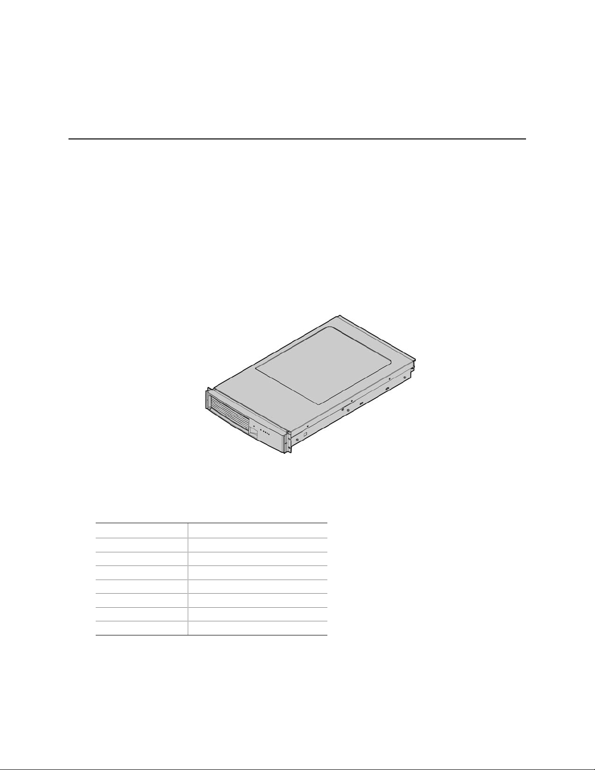
Figure 1 provides a diagram of the front and top of the server system, with the chassis cover in place.
Figure 1. Server System Front
Table 2 provides the system dimensions and weight.
Table 1. Physical Specifications
Specification Value
Height 3.4 inches (87 mm)
Width 17.7 inches (449 mm)
Depth 29.4 inches (747 mm)
Front clearance 3 inches (76 mm)
Side clearance 1 inch (25 mm)
Rear clearance 6 inches (152 mm)
Weight (note 1) 65 lbs (30 kg)
Note 1. The system weight listed above is an estimate for a fully configured system and will vary depending on the number
of peripheral devices and add-in cards as well as the number of processors and DIMMs installed in the system.
Table 2 provides a list and brief description of the features of the server system.
23
Page 24

Table 2. Feature Summary
Feature Description
Compact, high-density
system
Configuration flexibility
Serviceability
Availability
Manageability
Upgradeability and
investment protection
System-level scalability
Front panel
Rack-mount server with a height of 2U (3 1/2 inches) and a depth of 28 inches
• 1-2 way capability in low profile and cost effective packaging
• Stand-alone system including external I/O slots/disk expansion as needs
grow
• Intel Itanium 2 processor support
• 16-GB Double Data Rate (DDR) Synchronous Dynamic Random Access
Memory (SDRAM) memory support
• Front access to hot-swap hard drives
• Hot-swap fans
• Front access to hot-swap power supplies
• Dockable power to main board
• System power and reset status LEDs
• System ID switch on front panel and LEDs on front and back
• Color-coded parts to identify hot-swap and non-hot-swap serviceable
components
• Three PCI-X slots
• Three hot-swap 350-W power supplies in a redundant (2+1) configuration
• Dual redundant power cords (1+1) when three power supplies are present
• Six hot-swap system fans in a redundant (5+1) configuration
• Two hot-swap 1-inch Ultra320 SCSI hard drives
• Remote management
• Emergency Management Port (EMP)
• Intelligent Platform Management Interface (IPMI) 1.5 compliant
• Wired For Management (WfM) 2.0 compliant
• Remote diagnostics support
• Supports Intel Itanium 2 processors
• Field upgradeable to next generation (Montecito) processor family
• Multi-generational chassis
• Up to 16-GB DDR SDRAM (using 2-GB DIMMs)
• One to two Intel Itanium 2 processors
• External I/O (3 slots) / disk expansion
• External SCSI connector
• System Power switch and LED
• System Reset switch
• System Diagnostic Interrupt (SDINT)
switch
• System ID switch and LED
• System Status LED
• Hard Drive Fault LED
• LAN1 & LAN2 Status LEDs
• Video Connector
• Dual USB 1.1 Ports
24
Page 25
External Chassis Features
System controls and indicators are located in several places on the chassis as follows:
• Chassis front:
Front panel: Front panel switches and LEDs
Peripheral bay: Hard drive LEDs
Power bay: Power Module LEDs and Power Supply LEDs
• Chassis rear panel: System ID LEDs and LAN port LEDs
Each of these areas is discussed below.
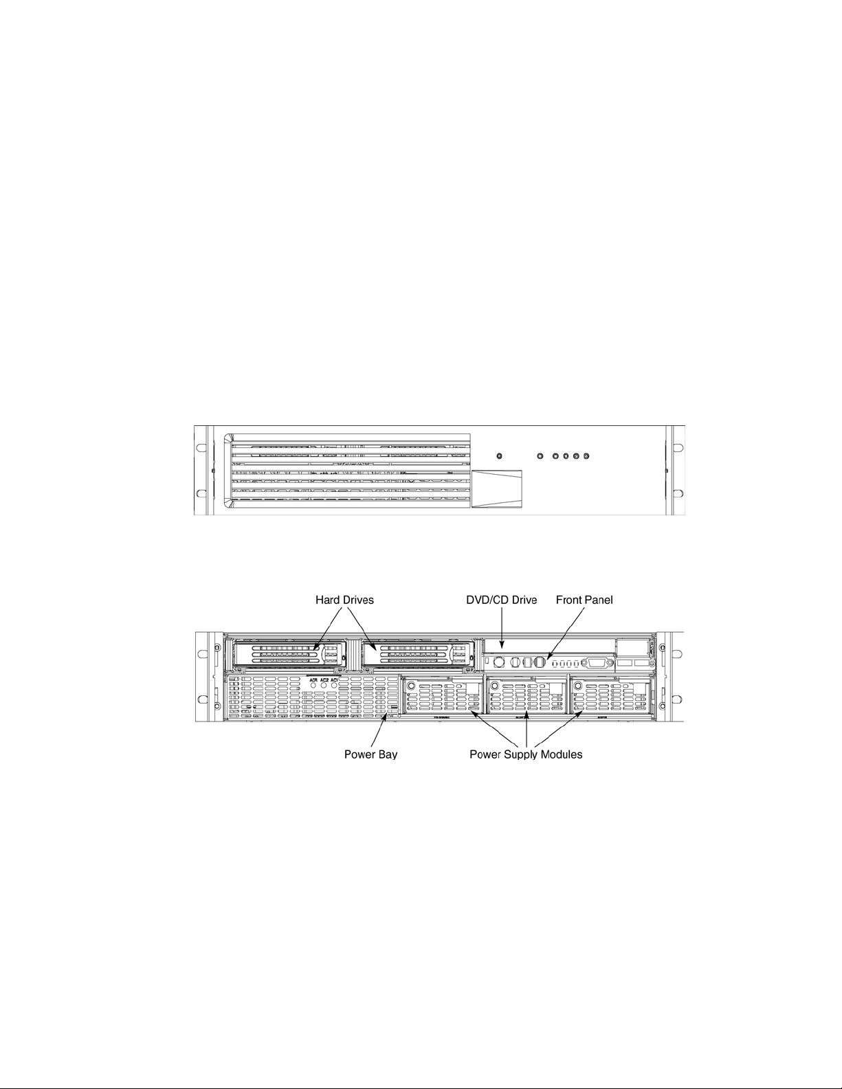
Chassis Front
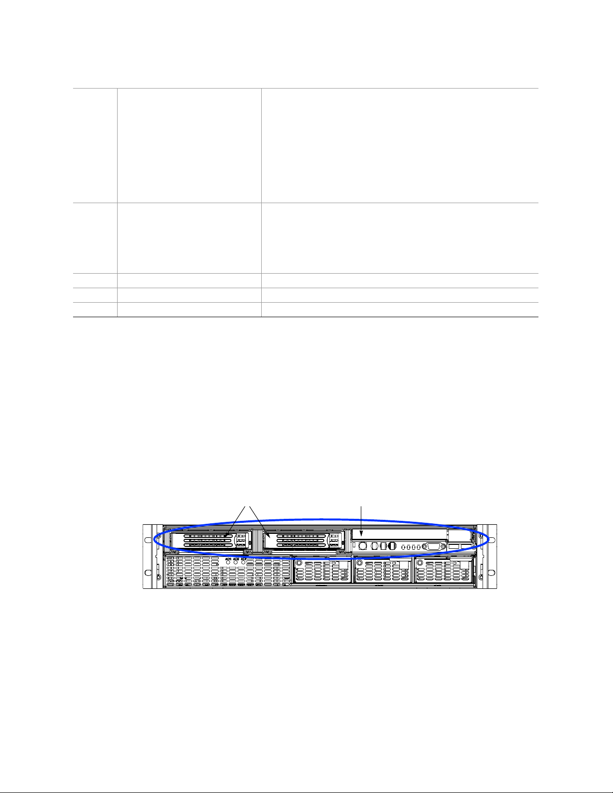
The following figure shows the front of the chassis with the snap-on bezel in place. The bezel must
be removed to access the front panel switches, power supplies, SCSI drives and DVD-CDRW
devices.
Figure 2. Server System Front with Bezel Installed
Figure 3. Server System Front with Bezel Removed
25
Page 26
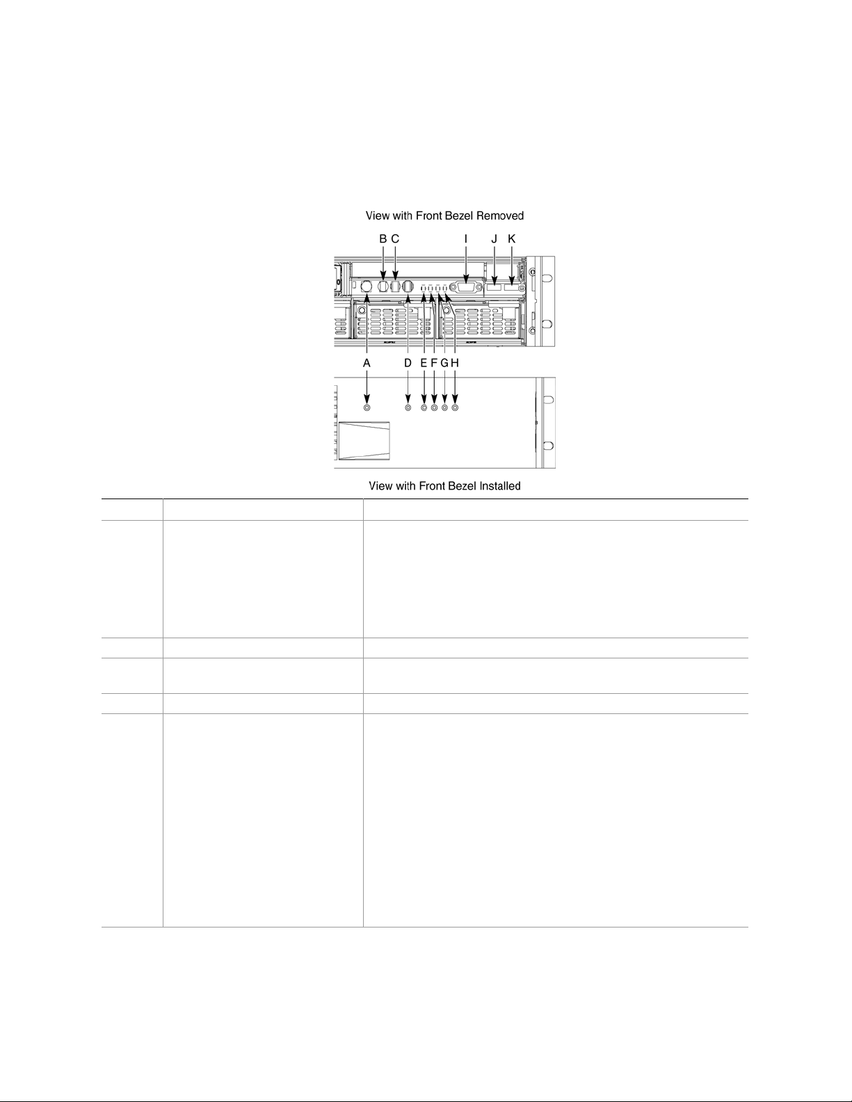
Front Panel
The front panel (Figure 4) is located at the right side of the server system, at the front of the chassis.
The front control panel displays status lights for system status, hard drives, and power supplies.
Callout Control, Connector, Indicator Description
A System Power switch & LED
B System Reset switch Resets the system.
C SDINT (System Diagnostic
Interrupt) switch
D System ID switch and LED (Blue) System identification switch and light
E System Status/Fault LED
(Green/Amber)
Toggles system power
LED State ACPI
Off Power off No
On Power on No
Off S5 Yes
On S0 Yes
Asserts SDINT
Indicates system status.
LED State Description
Off Not ready Post err/NMI Ev/CPU missing
Green,
solid
Green,
blinking
Amber,
solid
Amber,
blinking
Ready No Alarms
Ready – Degraded CPU Fault, DIMM killed
Critical Alarm Critical of Pwr Flt, Fan, Voltage,
and Temperature failures.
Non-Critical Alarm Non-Critical of redundant Pwr
Flt, redundant Fan, Voltage,
and Temperature failures.
26
Page 27
F Hard Drive Fault LED (Amber)
G, H LAN1, LAN2 Status LEDs
(Green)
I Video connector Video port, standard VGA compatible, 15-pin connector
J USB3 connector USB port 3, 4-pin connector
K USB4 connector USB port 2, 4-pin connector
Indicates hard drive subsystem fault status.
LED State Description
Off Drive Missing Slot Empty, Online, Prepare for
removal.
On Inactive Drive Failed
Blinking Drive Identity, Rebuild,
Predictive Fail, Rebuild
Interrupt or Rebuild on empty
slot.
Indicates LAN activity status.
LED State Description
Off Idle
On Inactive No Access
Blinking Active Access
Figure 4. Front Panel Controls, Indicators, and Connectors
Peripheral Bay
The peripheral bay (Figure 5) supports up to two 1-inch hot-swap Ultra320 SCSI hard drives and
one ½-inch IDE DVD/CD-ROM drive.
The peripheral bay supports Low Voltage Differential (LVD) SCSI disk drives only. Single-Ended
(SE) SCSI devices are not supported in the peripheral bay, however SE device support is available
via the secondary external SCSI channel located at the rear of the chassis.
Hard Drives DVD/CD Drive
TP00296
Figure 5. Peripheral Bay
27
Page 28
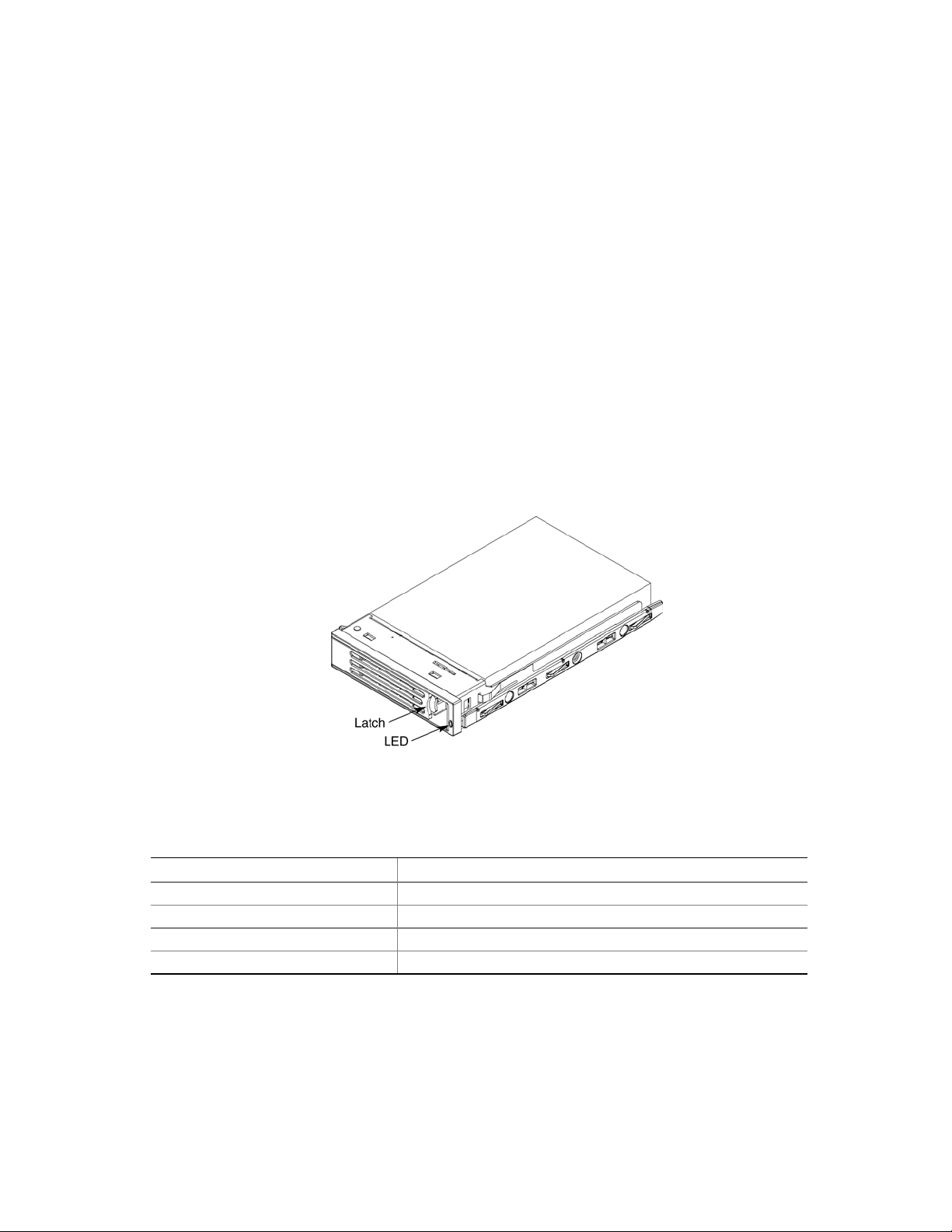
Hot-swap Hard Drive Carrier
The hot-swap hard drive carrier accepts 15,000-RPM and slower Ultra320 SCSI technology SCAtype hard drives. The peripheral bay supports Low Voltage Differential (LVD) SCSI disk drives
only. Single-Ended (SE) SCSI devices are not supported in the peripheral bay. SE drives are only
supported on the external SCSI connector. Refer to the Intel
®
Server System SR870BH2 Hardware
and Operating System Validation List for details on tested devices. Contact your Intel
representative to obtain this list.
Hard drive carriers that accommodate 3.5-inch by 1.0-inch SCSI disk drives are required as part of
the hot-swap implementation. The disk drive is attached to the carrier with four fasteners, and is
retained in the chassis by a locking handle. Figure 6 shows a hard drive carrier that has been
removed from the peripheral bay. The drive is accessed by pressing the latch to release the drive
carrier door, then pulling out on the door.
The SCSI backplane board contains a dual-color LED for each hard drive. The LED can be seen at
the right edge of the carrier, as shown in the figure. The LED displays the drive status, as described
in Table 3.
Table 3. SCSI Hard Drive LED Details
Feature Description
Green, flashing Indicates the hard drive is active
Yellow/Green flashing Indicates a hard drive fault and hard drive is powered
Yellow/Blank flashing Indicates a hard drive fault and hard drive is not powered
Not illuminated Indicates no hard drive is installed in the bay
28
Figure 6. Hard Drive Carrier
Page 29
Removable Media Drive Bay
CAUTION
The DVD/CD-ROM drive cannot be hot-swapped. In order to add, remove
or replace a DVD/CD-ROM drive, the system must be powered down, power
sources unplugged and the top cover of the chassis must be removed to
access the DVD/CD-ROM drive area.
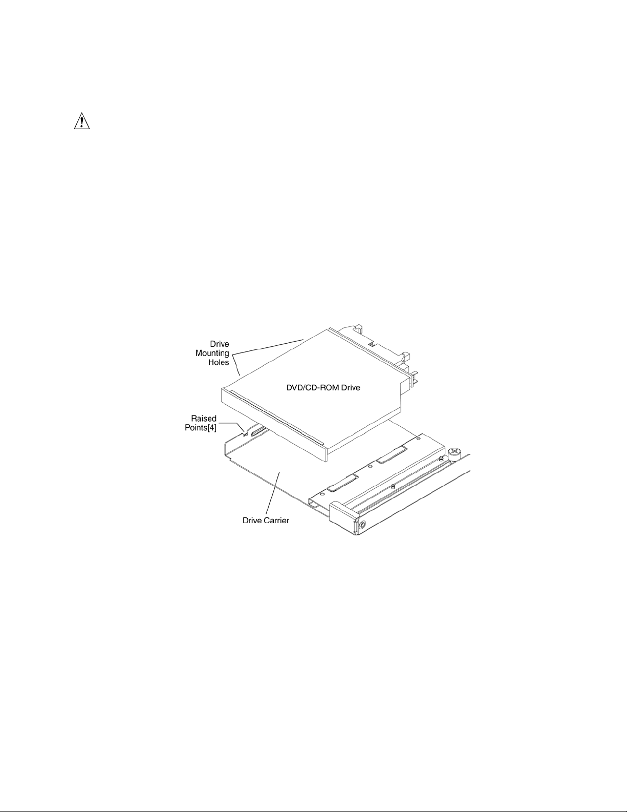
The slim-line DVD/CD-ROM drive is installed in a drive carrier that is inserted form the rear of the
peripheral bay. This device is not hot-swappable; you must switch off system power, remove all
power cords, open the chassis and then remove the peripheral bay to remove or install a CD-ROM
or DVD-ROM drive.
The CD-ROM/DVD-ROM drive snaps into the carrier as shown in Figure 7 and is secured by four
raised points. The raised points line up with the mounting holes on the sides of the drive. Two of
these mounting points are spring loaded and two are stationary.
Figure 7. DVD-ROM / CD-ROM Drive Installation
29
Page 30
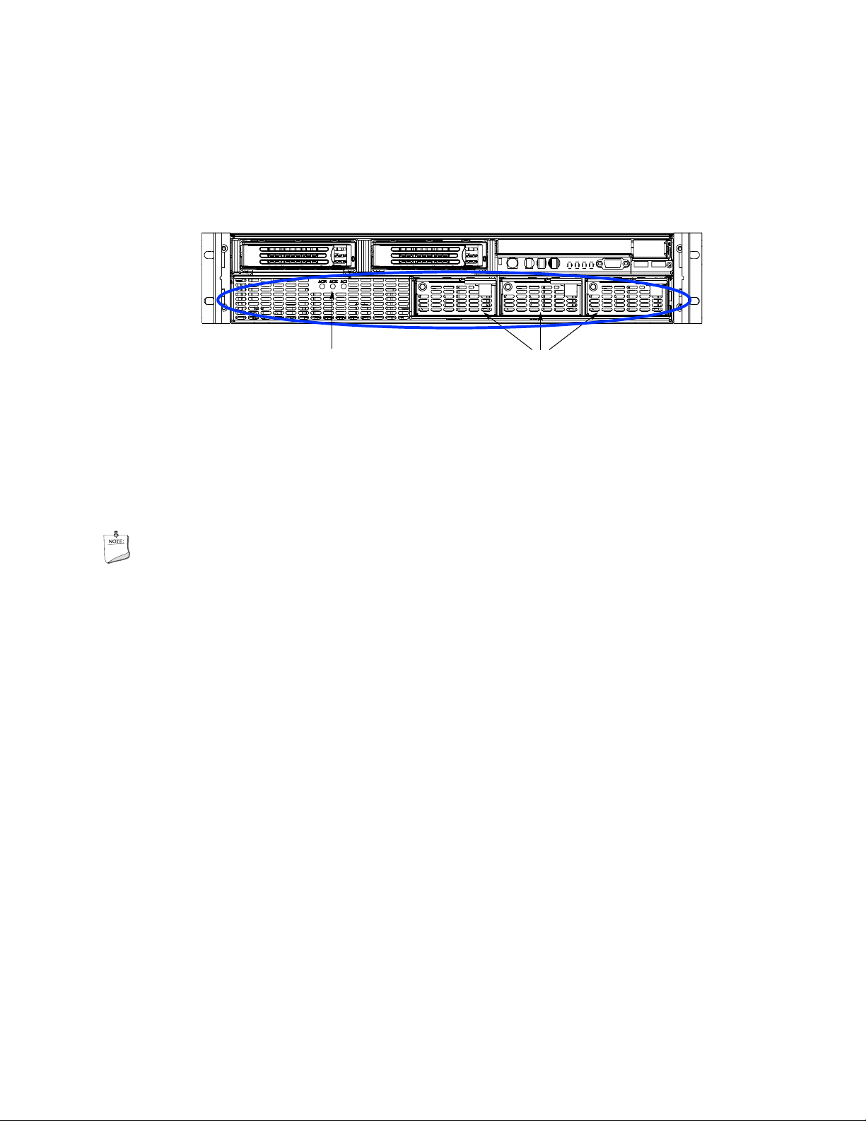
Power Bay
The power bay (Figure 8) is located in the lower front of the system. Redundant power status LED
indicators are in the left portion of the power bay and three hot-swap power supply modules dock
into the three bays on the right.
Power Status LEDs Power Supply Modules
TP00295
Figure 8. Power Bay
The power subsystem can be configured as follows:
• Three power supply modules installed, (2+1) redundancy
• Two power supply modules installed, non-redundant
NOTE
The power supply modules must be populated from right to left. The left
power supply module is optional in a non-redundant configuration. If no
module is installed in the left slot, a filler panel is required for proper system
cooling.
Two power supply modules are capable of handling the worst-case power requirements for a fully
configured server system. This includes two Intel Itanium 2 processors, 16 GB of memory, three
PCI add-in cards, two hard drives, and a DVD-ROM / CD-ROM drive.
When the system is configured with three power supply modules, the hot-swap feature allows you
to replace a failed power supply module while the system is running.
The power subsystem receives AC power through two power cords. When three power supply
modules and two power cords are installed, the system supports (1+1) power cord redundancy.
This feature allows the system to be powered by two separate AC sources. In this configuration,
the system will continue to function without interruption if one of the AC sources fails.
30
Page 31

The AC power status LEDs in the power supply module provide information on the status of the
power sources. The LEDs are shown Figure 9. The table below the figure defines the possible
LED states.
LED Description
AC1 (green) On - AC input #1 available.
Off - AC input #1 unavailable or below voltage threshold to power up the system.
AC2 (green) On - AC input #2 available.
Off - AC input #2 unavailable or below voltage threshold to power up the system.
ACR (green) On - redundant feature is available.
Off - redundant feature is not available
Figure 9. AC Power Status LEDs
The power redundancy feature requires that each of the following conditions be present.
• AC input #1 available
• AC input #2 available
• Power good signals asserted from all three power supply modules
• TS-OK signal is asserted
31
Page 32

Chassis Rear
Figure 10 shows the rear of the system.
Callout Description
A
B AC input power connectors (two)
C External SCSI connector1
D System ID switch
E System ID LED (blue)
F
G Serial port2, RJ45 connector
H Two USB 1.1 ports, 4-pin connectors (USB0 on bottom, USB1 on top)
I Video port, standard VGA compatible, 15-pin connector
Notes:
1. External SCSI bus supports both LVDS and SE signals via the external SCSI connector.
2. EMP access is provided via shared serial port.
PCI Slots
Slot 1 100-MHz, 64-bit PCI-X slot, full length
Slot 2 100-MHz, 64-bit PCI-X slot, full length
Slot 3 133-MHz, 64-bit PCI-X slot, full length
Two LAN ports, RJ45 connector (LAN1 on bottom, LAN2 on top)
LAN port LEDs:
Status LED (Green) On – Ethernet link is detected
Off – no Ethernet connection
Blinking – Ethernet link is active
Speed LED
(Green/Amber)
Off – 10 Mbps
Green On – 100 Mbps
Amber On – 1000 Mbps
Figure 10. Chassis Rear Features
32
Page 33

Internal Chassis Features
WARNING
Only qualified technical personnel should access any internal system
component. Some exposed circuits exceed 240 VA and may cause injury
if accidentally contacted.
Electronics Bay
The electronics bay, shown in Figures 11 and 12, consists of the following:
• Main board
• PCI riser board
• Two processor locations and two power pod locations
• Eight DIMM slots
• Air duct for the processor area
• PCI riser bracket to support PCI riser board and PCI cards
• Connectors, switches and LEDs at the rear of the chassis (see Figure 10)
Figure 11. Electronics Bay
33
Page 34

Figure 12. Electronics Bay (subassembly removed)
Cooling Subsystem
CAUTIONS
The chassis top cover must be installed and closed for proper system cooling.
Cooling components must be hot-swapped within a limited time period. This
time period applies only to the time that the cooling component is removed
from the system, not from the time of failure.
34
Page 35

The cooling subsystem consists of a hot-swap, redundant (5+1) system fan array installed in the fan
bay. The single bank of six Delta* FFB0612EHE-S18Z hot-swap system fans provide the airflow
necessary to cool the system components. These fans are installed in the fan bay that is located
within the power bay. The fans connect to the fan baseboard. Figure 13 shows the location of the
fans in the power bay.
Figure 13. Power Bay (removed from chassis)
35
Page 36

Figure 14 shows the cooling subsystem layout with the airflow direction indicated.
Figure 14. Cooling Subsystem Layout
The server system supports only a fully populated system fan configuration. However, the system
will continue to meet thermal specifications with either a system fan or a power supply failure. The
power supply redundancy feature applies to systems with three power modules installed.
If a fan fails, system cooling is maintained and the system continues to operate while the failed fan
is being hot-swapped. All system fans have tachometer output, internal speed control, and external
Pulse Width Modulation (PWM) speed control.
A failure is detected when the RPM of a fan falls below a predetermined minimum threshold
(Approx. 5000 RPM). If a system fan falls below this threshold, all fans will be boosted to operate
at a higher speed (Approx. 8500 RPM)
The fans will also be boosted to the higher speed if a power supply fails for any reason (including
loss of AC power). The fans will not be boosted if the Redundant (ACR) power supply fails. If the
redundant power supply fails, the system fans will not be affected.
When boosted, all fans remain at high speed until the failed fan or power supply is replaced. When
a fan replacement is detected by a change in state of the fan presence signal. After a failed fan is
replaced, the fans return to the lower speed and fan failure monitoring at the lower speed levels is
reactivated.
When a power supply fails and is replaced, the replacement is detected by server management.
36
Page 37

NOTES
Do not attempt to operate this system with less than a fully populated, six
system fan configuration.
To maintain adequate cooling for system components, the swap process must
be completed in two-minutes. This period only applies to the time that the
fan or power supply is removed from the system, not from the time of failure.
A system fan failure is indicated by the corresponding fan LED and by the Cooling Fault LED on
the front panel. The system fan LEDs are shown in Figure 15. The LED is amber and turns on if a
system fan failure occurs. These LEDs can be seen only when the top cover is removed from the
chassis.
Figure 15. System Fan Status LED
37
Page 38

Power Subsystem
Power Supply Modules
The power supply modules are Server System Infrastructure (SSI) compliant, universal AC input
with Power Factor Correction (PFC) Thin Power Supplies (TPS). The power supply modules are
rated at 350 W each. The combined continuous output power for all outputs has been designed
such that they will not exceed 650 W.
The DC output specification for the power supply is met by two power supply modules operating in
the power bay. A third power module may be inserted to enable redundancy. When operated in
parallel, the power modules share the total load currents equally within the limits specified, and
meet all performance requirements. Two power supply modules are capable of handling the worstcase power requirements for a fully configured system: Two processors, 16 GB of memory, three
PCI-X add-in cards, two hard drives and a DVD or CD drive.
In the unlikely event that a power module fails in a redundantly paralleled group, or upon the
removal of an operational or failed supply from a redundantly paralleled group, the action will not
cause DC output transients in excess of specified limits. Conversely, adding an operational or
failed supply to a paralleled group will not cause DC output transients in excess of the limits
specified.
Redundant AC Power Source Operation
The power bay has two AC inlets, labeled AC1 and AC2, located at the rear of the chassis. AC1 is
connected to the inputs of power supply module PS1. AC2 is connected to module PS2 and the
redundant power module PS-Shared, through normally closed transfer switch contacts.
• If AC1 input fails or exceeds the specified voltage range, AC2 will transfer power to the two
modules located in the positions labeled PS2 and PS-Shared.
• If AC2 input fails, the AC transfer switch automatically switches from AC2 to AC1. As a
result, AC1 connects to the two power supply modules located in locations PS1 and PS-Shared.
After AC2 recovers, the AC transfer switch resets to its original state. This feature allows the
system to be powered by two separate AC sources. In this configuration, the system continues
to operate without interruption if one of the AC sources fails.
Processor Power Pods
Dedicated power pods supply power to each processor. The input connector of the power pod is
connected to the 12 VDC power on the main board via a short ‘Y’ cable. The output connector of
the power pod mates directly with the edge of the processor package.
38
Page 39

2 Board Set Description
This chapter highlights the main features of the board set. The board set contains the following:
• Main board
• PCI riser board
In addition, the server contains the following system boards:
• SCSI board
• Peripheral board
Major components of the board set include:
• Intel Itanium 2 processors
• Intel E8870 chip set
• High-capacity DDR SDRAM memory
• High-bandwidth I/O subsystem supporting PCI and PCI-X
Figure 16 displays a block diagram of the system and the board set within the system.
39
Page 40

Main Board
Power Pod
ItaniumR 2
LPC
FWH
HL-2
P64H2
ItaniumR 2
FSB
SNC-M
SP1
SP2
VHDM Connector
SIOH
133 MHz PCI-X
100 MHz PCI-X
100 MHz PCI-X
Power Pod
RDRAM0
RDRAM1
RDRAM2
RDRAM3
PCI Riser
HL-2
HL-1.5
BMC
SCSI
320
DIMM
DIMM
DIMM
DIMM
DIMM
DIMM
DIMM
DIMM
PCI-X
External SCSI
Super IO
Dual GBit
Ethernet
EMP
USB Port
USB Port
Video Port
Ethernet Port
Ethernet Port
External SCSI
Connector
MRH-D
MRH-D
MRH-D
MRH-D
FWH
LPC
ICH-4
PCI 33
Video
VHDM Connector
IDE
2x USB
P64H2
PCI-X
VGA
Docking Connector
Internal SCSI
SCSI CableFlex Cable
Power Bay
To SCSI
Backplane
Power Supply
Power Supply
Power Supply
USB Port
USB Port
Video Port
IDE Cable
Front Panel
DVD Adapter Board
DVD/CD
Ribbon
Cable
Y-Cable
SCSI Backplane
From Power
Bay
Hot Swap SCSI Drives
Figure 16. Main Board Layout
40
Page 41

Main Board
The main board supports the following features:
• Two Intel Itanium 2 processor sockets and power pod sites
• Eight 184-pin, DDR-SDRAM DIMM sockets
• SNC-M (Scalable Node Controller) of the E8870 chip set
• Four Memory Repeater Hubs – DDR (MRH-D) components of the E8870 chip set
• One P64H2 PCI-X bridge component (to drive SCSI controller and NIC)
• SCSI Ultra320 Controller
• Network Interface Controller (NIC) 10/100/1000 Ethernet controller that provides two LAN
ports
• One I/O Control Hub 4 (ICH4) component
Four USB ports (two at the rear, two through the front panel)
One IDE bus routed through the flex cable to the peripheral board supporting one ATA33
master device
• Low Pin Count (LPC) Super I/O* with one external serial port and an internal header for a
second port
• Integrated ATI* Rage* XL video controller and memory with two video ports – one at the rear
and one through the front panel
• 8-MB Flash using four Firmware Hub (FWH) components
• Two VHDM connectors for PCI riser board
• Two retention mechanisms for processors and power pods
• In-Target Probe (ITP) port
• 200-MHz Front Side Bus (FSB)
• Four 400-MHz Rambus channels for memory interface
• Core ratio programming via the SNC-M
• Server management logic support
• Joint Test Action Group (JTAG) / boundary scan support through ITP or external source
• Clock buffering
• Six I
• Embedded D2D converters
• BMC server management controller
• Power control - Advanced Configuration and Power Interface (ACPI)
• Speaker control
• I
2
C system management buses (SMBus)
2
C logic
Includes Field Replaceable Unit (FRU) device ID that is accessed through a private I
Temperature sensors
2
C bus
41
Page 42

Processor Sockets
Each Intel Itanium 2 processor plugs into a 700-pin Zero Insertion Force (ZIF) socket. Each
processor is powered by a 12-V power pod located adjacent to the processor on the main board.
Attached to the top of each processor is a heat sink that dissipates thermal energy.
Memory Subsystem
The basic architecture of the memory subsystem is as follows:
• The DIMMs reside on the main board, between the PCI riser assembly and the chassis.
• Four Rambus channels run from the Scalable Node Controller (SNC) to each of the four
Memory Repeater Hubs (MRH-D).
• There is one MRH-D device per Rambus channel.
• Each MRH-D supports two DDR branch channels.
• Each DDR branch channel supports two 184-pin DDR DIMMs.
• The server system includes eight DIMM connectors in two rows.
• Each row of DIMM sockets supports four DDR DIMMs, one channel of each MRH-D, which
collectively make up a cache line.
The DIMM socket locations are shown in Figure 17.
Figure 17. Location of Memory DIMMS
42
Page 43

NOTES
The BIOS automatically detects, sizes, and initializes the memory array,
depending on the type, size, and speed of the installed DIMMs. The BIOS
reports memory size and allocation to the system through configuration
registers.
The system does not support mixed-sized DIMMs or DIMMs from different
vendors within the same row.
DIMMs must be populated in groups of four, referred to as a row. Row 1 consists of DIMM
sockets 1-4 and row 2 consists of DIMM sockets 5-8. The DIMM sockets in each row are not sideby-side; see Figure 17 to identify each socket and row.
Within a single row, all DIMMs must be identical, both in DIMM size and the number of devices
on the DIMM. Each of the two DIMM rows can be populated with DIMMs that use different
technologies, but for the best performance, the amount of memory on each MRH-D DDR branch
channel should be the same to enable the benefits of memory interleaving.
SCSI Controller
The LSI-531030 SCSI controller (U320) on the main board provides one primary channel to the
internal SCSI backplane and a secondary channel via an external SCSI connector at the rear of the
chassis. This device interfaces to the SIOH at clock frequencies up to133 MHz through one
channel of the primary P64H2, also located on the main board. The 53C1030 is a fully autonomous
device, capable of managing multiple I/O operations and associated data transfers from start to
finish without host intervention.
While the internal channel supports only Low Voltage Differential (LVD) signaling, the external
channel supports both LVD and SE (single-ended) signaling. With LVD signaling, the channels
can each support a maximum data rate of 320 MB/sec.
Network Interface Controller
The onboard network interface is composed of one Intel 82546EB Dual Port Gigabit Ethernet
controller connected to the second channel of the primary P64H2 PCI-X bridge, located on the
main board, at clock frequencies up to133 MHz. The 82546EB is a single component with two
fully IEEE 802.3-compliant Ethernet interfaces. It provides two stacked RJ45 ports at the rear of
the chassis.
This network interface supports Ethernet applications at 1000Base-T, 100Base-T, and 10Base-T
(802.3, 802.3u and 802.3ab) and enables network manageability implementations required for
remote control and alert over LAN.
43
Page 44

Video Controller
The onboard, integrated ATI RAGE XL 64-bit SVGA chip contains an SVGA controller that is
fully compatible with industry video standards. The video sub-system implements 8 MB of
10-nanosecond onboard video memory.
The video controller supports pixel resolutions of up to 1600 x 1200 and up to 16.7 million colors
and provides hardware-accelerated bit block transfers of data. The SVGA controller supports
analog VGA monitors (single and multiple frequency, interlaced and noninterlaced) with a
maximum vertical retrace noninterlaced frequency of 100 Hz.
Video connectors are located at both the front and the rear of the chassis. The connectors are auto
sensed and only one can be used at a time.
IDE Controller
The IDE controller is contained within the Intel® ICH4 (82801DA). The IDE controller is a
multifunction device on the I/O board that acts as a PCI-based Fast IDE controller. Although the
server system implements a single IDE channel on the peripheral board, which supports a CD/DVD
drive at ATA-33 speeds, the IDE controller supports the following:
• PIO and IDE DMA/bus master operations
• Mode 4 timing
• ATA-100 (100 MB/sec using ultra DMA transfers)
• Buffering for PCI/IDE burst transfers
• Master/slave IDE mode
Baseboard Management Controller (BMC)
The Baseboard Management Controller and its associated circuitry reside on the main board. The
BMC autonomously monitors system platform management events and logs their occurrences in the
nonvolatile System Event Log (SEL). This includes events such as over-temperature and overvoltage conditions, and fan failures. The BMC provides the interface to the monitored information
so system management software can poll and retrieve the present status of the platform.
The BMC provides the interface to the nonvolatile Sensor Data Record (SDR) Repository. Sensor
Data Records provide a set of information that system management software can use to
automatically configure itself for the number and type of IPMI sensors (such as temperature and
voltage sensors) in the system.
44
Page 45

The following is a list of the major functions of the BMC:
• System power control, including providing Sleep/Wake push-button interfaces for ACPI
• Platform Event Paging / Platform Event Filtering
• Power distribution board monitoring
• Temperature and voltage monitoring
• Fan failure monitoring
• Processor presence monitoring (no processors installed)
• Interlock monitoring
• Speaker beep capability on standby and when system is powered up
• Intel Itanium 2 processor SEEPROM interface (for processor information ROM and scratch
EEPROM access)
• Processor temperature monitoring
• Processor core ratio speed setting
• Chassis general fault light control
• Chassis cooling failure light control
• Chassis power fault light control
• Chassis power light control
• Chassis ID LEDs control
• System Event Log interface
• Sensor Data Record repository interface
• SDR/SEL timestamp clock
• Board set FRU information interface
• Fault resilient booting
• System management watchdog timer
• Front panel system diagnostic-interrupt handling
• Platform Management Interruption / System Diagnostic Interrupt status monitor
• Event receiver
• System interface to the IPMB (via system interface ports)
• IPMI Management Controller Initialization Agent
• Emergency Management Port interface
• Serial/modem and LAN alerting
The firmware for the BMC is field-upgradeable using the Firmware Update utility. For information
on the Firmware Update Utility, see Running the Firmware Update Utility.
45
Page 46

PCI Riser Board
The PCI riser board supports the following features:
• One Server I/O Hub (SIOH) component of the E8870 chip set
• One P64H2 component
• Three non-hot-plug PCI slots
One 64-bit, 133-MHz PCI-X, full length
Two 64-bit, 100-MHz PCI-X, full-length
• One integrated D2D
• Server management logic
2
• I
C logic
FRU device ID accessed through a private I
Temperature sensor
2
C bus
SCSI Backplane Board
The SCSI backplane board communicates with the main board via a 68-pin SCSI cable and a flex
cable. It contains two industry-standard 80-pin Single Connector Attachment (SCA)-2 connectors
for hot-swap hard drives. Ultra320 or lower SCSI technology SCA type hard drives can be
installed in this carrier. The backplane board accepts hard drives up to 15,000 RPM.
The features supported by the SCSI backplane board include the following:
• Monitoring the SCSI bus for enclosure services messages and acting on them appropriately.
Examples of such messages include: activate a drive fault indicator, power down a drive that
has failed, and report SCSI backplane temperature.
• SAF-TE intelligent agent, which acts as proxy for “dumb” I
communications. “Dumb” I
NOTE
2
C devices are those that have no bus mastering capability.
Because all hard drives have different cooling, power and vibration
characteristics, Intel validates specific hard drive types in the system.
The SCSI backplane provides three main functions for the system:
• Passes the SCSI signals between the main board and the SCSI drives
• Provides hooks for enclosure management
• Provides an I
2
C server management interface
2
C devices during intrachassis
46
Page 47

The SCSI backplane functional blocks include the following:
• Ultra320 LVD SCSI bus passes SCSI signals between the SCSI drives and the main board
A standard 68-pin SCSI connector provides the SCSI connection from the main board to
the SCSI backplane.
Two 80-pin (SCA-2 blind-mate) connectors are located on the SCSI backplane board to
mate with hot-swap LVD SCSI drives in the drive bay.
• Fault Tolerant Enclosure Management
SAF-TE
SCSI power control
LED control logic
• Server management
2
I
C interface
2
I
C Serial CMOS EEPROM (FRU)
Temperature sensor
QLogic* GEM359* SCSI Hot-swap Controller
The QLogic GEM359 Hot-swap Controller resides on the SCSI backplane board. The primary
functions of the GEM359 are as follows:
• Implements the SAF-TE command set
• Controls the SCSI hard drive fault LEDs
• Provides a path for management information via the SCSI
• Retrieves hard drive fault status, SCSI backplane temperature, and fan failure information via
the IPMB
• Queries the status of the power distribution board by retrieving information from the BMC via
the IPMB
• Controls hard drive power-on and power-down, facilitating hot-swapping
47
Page 48

Peripheral Board
The peripheral board provides three main functions for the system:
• Passes the IDE signals between the main board and the DVD drive
• Provides the front panel interface for the system
• Provides I
Peripheral Board Functional Blocks
• IDE bus passes IDE signals between the IDE DVD and the main board
The 120-pin flex cable connector from main board provides IDE connectivity and auxiliary
Single IDE channel pass-thru connection to IDE connector for support of an IDE peripheral
• Front panel functions
Two USB 1.1 connections
Power, Reset, SDINT and ID buttons
LEDs for power, both NIC channels, ID, system and drive failure
VGA connector providing video from main board controller
• Server management
I
Temperature sensor
2
C server management interface
signals
2
C isolation to SCSI board
Peripheral Interface
The server connects to supported peripheral devices through interfaces located on the main board.
The ICH-4 on this board provides the following:
• Four USB 1.1 ports (two located in front and two located at the rear)
• Two serial ports, one internal port (10-pin header) and one port at the rear (serial RJ45)
• One PCI connection to onboard video (VGA ports located front and rear)
• One IDE channel for the CD/DVD
48
Page 49

Server Management
The server management features are implemented using two microcontrollers: the Baseboard
Management Controller on the main and the Qlogic* GEM359 SCSI hot-swap controller on the
SCSI backplane board. For information about these microcontrollers, see:
• Baseboard Management Controller (BMC)
• QLogic* GEM359* SCSI Hot-swap Controller
49
Page 50

3 Configuration Software and Utilities
Utilities / Drivers on Resource CD
The Resource CD included with your server system includes the following utilities and drivers that
can be used to configure your system:
• LSI Logic SCSI Driver for Linux (64-bit) and Microsoft Windows* 2003 Server
• Utilities:
FRUSDR Loader
EFI Platform Diagnostics
System Maintenance Utility (SMU)
• SDRViewer
• SELViewer
• EFI Configuration Tool
The Resource CD includes a menu-driven program that can be used for the following:
• Create a diskette containing drivers for various operating systems.
• Install EFI Service Partition. The EFI service partition provides the ability to remotely access
the server via modem or LAN for the purpose of executing configuration/setup utilities and
diagnostics.
• Run EFI-based utilities.
Running Software Utilities Directly from the Resource CD
The following procedure allows you to run the software utilities directly from the Resource CD.
1. Insert the System Resource CD into the server’s CD-ROM drive before booting to EFI Shell.
2. Boot the system into EFI Shell; the EFI CD menu program launches automatically. If the EFI
CD menu program does not launch in the EFI Shell, mount and map to the CD drive and type
startup and press <Enter> to launch the EFI CD menu.
3. Move the curser to the Utilities and select the utility you want to run.
Power-on Sequence and Power-on Self-Test (POST)
Turning on the system causes POST to run and control to pass to the boot manager. From the boot
manager, you can choose to invoke the Extensible Firmware Interface (EFI) Shell or you can
choose to go to the Boot Maintenance menu.
50
Page 51

The following process occurs when you press the power button on the front control panel to power
up the server:
1. The server fans start.
2. POST begins running. POST is stored in flash memory. It checks the drive carriers,
processors, memory, keyboard, and most installed peripheral devices. During the memory test,
POST displays the amount of memory it is able to access and test. The length of time needed
to test the memory depends on the amount of memory installed.
3. Video appears on the monitor that is attached to the server and begins to display boot progress.
The AMI* BIOS banner displays the loaded versions of the BIOS, PAL, SAL, and EFI.
4. POST concludes and passes control to the boot manager.
5. From the boot manager, you can use arrow keys to highlight the option that invokes the EFI
shell operating system if it is installed, or you can highlight and select the Boot Maintenance
menu. Selecting the Boot Maintenance menu lets you configure boot options and other boot
environment variables. Booting to the EFI shell causes the following prompt to appear:
Shell>
6. When you see this prompt, you can load and start an operating system.
Extensible Firmware Interface Boot Manager
The EFI boot manager allows you to control the server’s booting environment. Depending on how
you have configured the boot options, after the server is powered up the boot manager presents you
with different ways to bring up the system. For example, you can boot to one of the following:
EFI Shell: An interactive environment that allows EFI device drivers to be loaded, EFI
applications to be launched, and operating systems to be booted. The EFI shell provides a set of
basic commands used to manage files and the system environment variables. For more information
on the EFI Shell, see The Extensible Firmware Interface (EFI) Shell.
Boot Options: Files that you include as boot options. You add and delete boot options by using
the Boot Maintenance menu. Each boot option specifies an EFI executable with possible options.
For information on the Boot Maintenance menu options, see Table 4.
Boot Maintenance Menu: A menu of items allowing you configure boot options and other boot
environment variables. Table 4 describes each menu item in the Boot Maintenance menu.
Table 4. Boot Maintenance Menu Options
Option Description
Boot from a File Automatically adds EFI applications as boot options or allows you to boot
from a specific file.
When you choose this option, the system searches for an EFI directory in all
EFI System Partitions in the system. For each EFI directory that the system
finds, it searches through that directory’s subdirectories for the first file that
is an executable EFI application. Each file that meets this criterion can be
automatically added as a boot option. In addition, legacy boot options for A:
and C: are also added if those devices are present.
With this option, you can launch a specific application without adding it as a
boot option. In this case, the EFI Boot Manager searches the root
directories of all of the EFI System Partitions present in the system for the
specified EFI application.
51
Page 52

y
Option Description
To boot from a file:
• At the menu, use the arrow key to select Boot from a File.
• Press <Enter> to select the option.
• Use the arrow key to choose the EFI file to boot from.
• Press <Enter> to select the option.
Add a Boot Option Adds a boot option to the EFI Boot Manager. You specify the option by
providing the name of the EFI application. You can provide either ASCII or
UNICODE arguments that the file might use.
Given the EFI application name and any options, the EFI Boot Manager
searches for the executable file in the same partitions and directories as
described in Boot from a File. When the file is found, it is executed.
To add a boot option:
• At the menu, use the arrow key to select Add Boot.
• Press <Enter> to select the option.
• Type in the name of the EFI application and press <Enter>.
• Select Save to NVRAM.
• Select Exit to return to the Boot Manager.
Delete Boot Options This feature allows you to delete a specific boot option or all boot options.
To delete boot options:
• At the menu, use the arrow key to select Delete Boot Option.
• Press <Enter> to select the option.
• Use the arrow keys to select the boot option to delete.
• Press <Enter> to select the option.
• Press <Y> to confirm your selection.
• Select Save to NVRAM.
• Select Exit to return to the Boot Manager.
Change Boot Order This feature allows you to control the relative order in which the EFI Boot
Manager attempts boot options. For help on the control key sequences you
need for this option, refer to the help menu. To change the boot order:
• At the menu, use the arrow key to select Change Boot Order.
• Use the arrow keys to select the Option to move.
• Press <u> to move up in the boot order.
• Press <d> to move down in the boot order.
• Select Save to NVRAM.
• Select Exit to return to the Boot Manager.
Manage BootNext Setting This feature allows you to select a boot option to use one time (the next
boot operation).
To manage boot next setting:
• At the menu, select Manage Boot Next Setting with the arrow
key.
• Select the Option to boot next with the arrow key.
• Press <b> to make this option the next boot option.
• Press <r> to reset.
• Select Save to NVRAM.
• Select Exit to return to the Boot Manager.
Set Auto Boot Timeout This feature allows you to define the value in seconds that pass before the
stem automatically boots without user intervention. Setting this value to
s
52
Page 53

Option Description
zero disables the timeout feature.
To set auto boot timeout:
• At the menu, select Set Auto Boot Timeout with the arrow key.
• Three options are available.
• Select the Choose Value option with the arrow key and enter a
value of “0” to disable auto boot.
• Select the Delete option with the arrow key and select the
Delete setting with the arrow key and press <Enter>.
• Choose a time out value of 65535 (0xFFFF) to allow you to
press any key while booting to EFI to disable timeout.
Select Console Output
Device
Select Console Input Device This feature allows you to select the device that the console receives
Select Standard Error Device This feature allows you to select the standard error device.
This feature allows you to select the device that the console output is
sent to.
To select the console output device:
• At the menu, select Manage Boot Next Setting with the arrow
key.
• Select the Option to boot next with the arrow key
• Press <b> to make this option the next boot option.
• Press <r> to reset.
• Select Save to NVRAM.
• Select Exit to return to the Boot Manager.
input from.
To select the console input device:
• At the menu, select Manage Boot Next Setting with the arrow
key.
• Select the Option to boot next with the arrow key.
• Press <b> to make this option the next boot option.
• Press <r> to reset.
• Select Save to NVRAM.
• Select Exit to return to the Boot Manager.
To select the standard error device:
• At the menu, select Manage Boot Next Setting with the arrow
key.
• Select the Option to boot next with the arrow key.
• Press <b> to make this option the next boot option.
• Press <r> to reset.
• Select Save to NVRAM.
• Select Exit to return to the Boot Manager.
53
Page 54

Cold Reset Performs a platform-specific cold reset of the system. A cold reset means a
full platform reset.
To perform a cold reset:
• At the menu, select Set Auto Boot Timeout with the arrow key.
• Press <Enter>.
• The system resets.
Exit Returns control to the EFI Boot Manager main menu. Selecting this option
displays the active boot devices, including a possible integrated shell.
The Extensible Firmware Interface (EFI) Shell
The EFI shell application allows other EFI applications to be launched, EFI device drivers to be
loaded, and operating systems to be booted. The combination of the EFI firmware and the EFI
shell provides an environment that can be modified to easily adapt to many different hardware
configurations.
The EFI shell provides a set of basic commands used to manage files and EFI NVRAM shell and
boot variables. A list of these basic commands is shown in Table 5. Descriptions of the EFI shell
commands are also available when operating in the EFI Shell. To access the descriptions, type
help and press the <Enter> key.
A detailed description of the commands is available on the EFI website. To obtain the document,
go to http://developer.intel.com/technology/efi
. To download the files, click on Tools and then EFI
Sample Implementation 1.10.14.60. The descriptions are in the Microsoft* Word* file named
EFI1.1ShellCommands.doc.
In addition to the standard shell commands available in the EFI Shell, the EFI environment allows
you to create your own shell commands and EFI applications. For detailed information about the
EFI Shell, its commands, and the ability to develop within the environment, refer to the EFI
Developer’s Guide at http://developer.intel.com/technology/efi
. Click on Tools and then EFI
Sample Implementation Version 1.02 to download the files to your hard drive. Review the
Microsoft Word file Efi_dg.doc.
To develop your own shell commands, download the EFI Application Toolkit under the Tools link
at http://developer.intel.com/technology/efi
Table 5. EFI Shell Commands
Command Description
<drive_name>: Changes drives. For example, entering fs0: and pressing
alias [-bdv] [sname] [value] Sets or gets alias settings
attrib [-b] [+/- rhs] [file] Views or sets file attributes
bcfg -? Configures boot driver and load options in EFI NVRAM
botmaint Launches Boot Maintenance Manager
break Executes a breakpoint
cd [path] Changes the current directory
the <Enter> key changes the drive
54
Page 55

Command Description
cls [background color] Clears the screen
comp file1 file2 Compares two files
connect [-r] [-c] Handle# ½DeviceHandle#
DriverHandle#
cp [-r] file [file] ... [dest] Copies files and directories, [-r] = recursive
date [mm/dd/yyyy] Gets or sets the date
dblk device [Lba] [Blocks] Performs a hex dump of BlkIo Devices
devices [-b] [-1XXX] Displays devices
devtree [-b] [-d] Displays device tree
dh [-b] [-p prot_id] | [handle] Dumps handle information
disconnect DeviceHandle#
[DriverHandle# [ChildHandle#]
dmem {address] [size] [;MMIO] Displays the contents of memory
dmpstore Dumps the variable store
drivers [-b] [-lXXX] Displays drivers
drvcfg [-c] [-lXXX] [-f] [-v] [-s] Invokes the driver configuration protocol
drvdiag [-c] [-lXXX] [-s] [-e] [-m] Invokes the driver diagnostics protocol
echo [[-on | -off] | [text] Echoes text to the standard output device or toggles script
edit [filename] Opens the text editor allowing you to create or edit a file
eficompress infile outfile Compresses an EFI file
Efidecompress infile outfile Decompresses an EFI file
endfor Provides a delimiter for loop constructs (scripts only)
endif Provides a delimiter for IF THEN constructs (scripts only)
for var in <set>
goto label Makes batch file execution jump to another label
guid [-b] [sname] Dumps known guid ids
help [-b] [internal_command] Displays help information
hexedit [[-f]FileName|[-d DiskName Offset
Size]|[-m Offset Size]]
if [not] condition then Provides conditional constructs (scripts only)
load driver_name Loads a driver
loadbmp [-c] [-t] [-i[UGA Instance]] file Displays a bitmap file on the screen
loadpcirom romfile Loads a PCI option ROM
ls [-b] [dir] [dir] ... Obtains directory listings
map [-bdvr] [sname[:]] [handle] Maps sname to device path
mem [address] [size] [;MMIO] Dumps Memory or Memory Mapped IO
memmap [-b] Dumps memory map
mkdir dir [dir] Creates a new directory
mm address [Width] [;Type] [n] Memory Modify: type = Mem, MMIO, IO, PCI, [n] for non
mode [col row] Sets or gets the current graphics mode
Binds the EFI driver to a device and starts the driver
Disconnects device from driver
echo
Edits in HEX mode
interactive mode when inside a .nsh file
55
Page 56

Command Description
mount BlkDevice [sname[:]] Mounts a file system on a block device
mv [src…] [dst] Move one or more files/directories to destination
pause Prompts to quit or continue (scripts only)
pci [bus_dev] [func] Displays PCI device information
rconnect DeviceHandle# [DriverHandle#
[ChildHandle#]] | [-r]
reset [reset_string] Performs a cold reset
rm file/dir [file/dir] Removes files or directories
setsize file Sets size of a new file
stall microseconds Delays for the specified number of microseconds
time [hh:mm:ss] Gets or sets the time
type [-a] [-u] [-b] file Displays the contents of a file
ver Displays version information
vol fs [volume_label] Sets or displays a volume label
Reconnects one or more drivers from a device
Firmware Upgrades
Use the Firmware Update Utility to upgrade the firmware. This utility is an EFI application that
updates the following server management controllers:
• Baseboard Management Controller (BMC)
• Hot-swap Controller (HSC)
You can run the utility interactively by providing commands through the EFI shell, or you can run
it in non-interactive mode by supplying the command with any options. For information on the
command-line options, see Table 6.
NOTE
Review the firmware release notes that come with the software for additional
instructions before updating either the boot code or the operational code.
56
Page 57

Running the Firmware Update Utility
The following procedure shows how to use the interactive method to upgrade the firmware with the
Firmware Update Utility.
1. Boot to the EFI Shell.
2. Contact your Intel Sales Representative for the current release of the files:
FWUpdate.efi
IPMI.efi
<name>.hex
IPMIdriver.txt
Firmwareupdate.txt
<name>.txt
Where <name> represents the hex image for the controller being updated. For example, the files
lnbmc11.hex and lnbmc11.txt represent the firmware and release note files, respectively for BMC
release 11. Write down the name of the HEX file because you will need it later.
You can update the firmware either by the Firmware Update Utility’s command-line interface or
through the GUI interface.
Firmware Update with Command-line Interface
Table 6 describes the command-line options for the Firmware Update Utility.
Table 6. Firmware Update Utility Command-line Options and Parameters
Option or
Parameter
FWUpdate The name of the utility.
[Hex_File_Name] The name of the input hex file used for the update/verification. The file path can be
/h Or /? Display command-line help.
/uploadpia Upload the FW flash with the Platform Information Area (PIA) contained in the hex
/upload Upload the FW flash with the operational code contained in the hex file. The
/norestore When used in conjunction with /upload, the utility does not restore the user
/noverify When used in conjunction with /upload or /uploadpia, the utility does not compare
Description
specified with the file name. There is no default filename or extension.
file.
Platform Information Area (PIA) will also be uploaded, if it is present in the hex file.
Upon completion, the firmware is verified against the hex file to ensure the upload
was successful.
configuration settings after performing the update. Without this switch, the utility
saves the user configurations prior to updating the FW, and then restores the saved
user configuration settings after updating the FW.
the flash against the hex file after performing the update, as is usually done to verify
a successful update. When not used in conjunction with /upload or /uploadpia, this
switch has no effect.
57
Page 58

/ignorerevs When used in conjunction with /upload or /uploadpia, the firmware version in the
hex file is not checked. Without this switch, the utility only allows uploading a
version of the firmware that is greater than or equal to the version being replaced.
When not used in conjunction with /upload or /uploadpia, this switch has no effect.
/nopc When used in conjunction with /upload or /uploadpia, the platform check is disabled.
Without this switch, the utility only allows uploading firmware that is intended for the
target platform. The target platform is determined by reading the BIOS ID of the
system and compares it against the Platform Name field in the boot code info block
of the hex file. In the case of the PIA, the target platform is determined from the
Platform Group and Platform ID fields of the PIA info block. When not used in
conjunction with /upload or /uploadpia, this switch has no effect.
/bootena When used in conjunction with /upload, the boot-block of the device is uploaded in
addition to the operational code and PIA if present in the hex file. NOTE: An
external jumper may be required in order to enable the boot block to be uploaded.
On systems requiring the jumper, the boot block upload fails if the jumper is not set,
and an error is generated indicating that the boot block could not be uploaded.
However, the utility still attempts to upload the operation code and PIA, if present in
the hex file. This switch may only be used in conjunction with /upload.
/verify Verify the firmware. The utility compares the flash contents of boot code, operation
code, and PIA (if applicable), with that contained in the hex file.
/fwversion Display firmware version, for all supported devices in the system.
/secondary Select secondary controller; e.g. second hot-swap controller. The primary and
secondary controllers are identical, this switch indicates which one is being updated
or verified. Without this switch the primary controller is assumed. When not used in
conjunction with /upload or /verify, this switch has no effect.
/infoblock Display device info block of input hex file.
/nopause Suppresses keyboard wait at end of transfer or on an error. This switch allows
updates to be performed in a batch style environment without requiring user
interaction.
To run the Firmware Update Utility through the command-line interface:
1. Start the utility by typing: fwupdate [HEX File Name] [Options]
2. To view the command-line help, type:
fwupdate /h
or
fwupdate /?
3. To update boot block and the operational block of the firmware from the command-line
interface, type fwupdate [HEX File Name] /upload /bootena
An external jumper may be required in order to enable the boot block to be uploaded.
4. To update the operational block only from the command-line interface, type fwupdate
[HEX File Name] /upload
58
Page 59

After the update completes successfully, the utility verifies the update by reading back the
programmed code and comparing it to the HEX file.
5. Select the File menu and choose Exit to exit the utility.
6. If you need to update the firmware for additional controllers, repeat the above steps for each
controller.
7. Power down the system by pressing and holding the power button on the front control panel.
8. Disconnect the AC power cords from the system and wait 60 seconds.
9. Connect the AC power cords and power up the system by pressing the power button.
Firmware Update with GUI Interface
To run the Firmware Update Utility through the GUI interface:
1. Start the utility by typing fwupdate <name>.hex
In the command, <name>.hex is the file you wrote down earlier.
2. Wait for the HEX file to load and the utility to display its menu items.
3. Use the arrow keys to select the Update Flash menu item.
4. Press the <Enter> key.
5. The utility asks you to update the boot code and/or the operational code.
After the update completes successfully, the utility verifies the update by reading back the
programmed code and comparing it to the HEX file.
6. Select the File menu and choose Exit to exit the utility.
7. If you need to update the firmware for additional controllers, repeat the above steps for each
controller.
8. Power down the system by pressing and holding the power button on the front control panel.
9. Disconnect the AC power cords from the system and wait 60 seconds.
10. Connect the AC power cords and power up the system by pressing the power button.
BIOS Upgrades
The BIOS is implemented as firmware that resides in flash ROMs. Use the EFI (Extensible
Firmware Interface) based utility IFlash64.EFI to upgrade the BIOS.
NOTE
After you complete the Iflash64 BIOS update, you must clear the CMOS.
For information on how to clear CMOS, refer to CMOS Clear.
59
Page 60

BIOS Upgrade Procedure
A BIOS upgrade procedure can be done using the latest available System Update Package (SUP)
for the system. This is a script file that automatically runs IFlash64 and other firmware update
utilities. You can also use the IFlash64 utility to upgrade the BIOS using the following steps:
1. Boot to the EFI Shell. For information on how to boot the server, refer to The Extensible
Firmware Interface (EFI) Shell.
2. Copy IFlash64.EFI to a hard disk, CD-ROM disk, or EFI ramdisk (EFI ramdisk driver
required). The binary file contains the new BIOS. Refer to the update instructions provided
with each BIOS release for the most current instructions.
IFlash64 with Command-line Interface
Table 7 lists the command-line options for the IFlash64 Utility.
Table 7. IFlash64 Utility Command-line Options and Parameters
Parameter Description
Iflash64 The name of the utility.
[Volume_File_Name] Name of the BIOS binary volume file used for the update. The file path can be
specified with the file name. There is no default file name.
/d Display header and FLASH areas information of volume file.
/f Load default values from CMOS on next boot.
/quiet Quiet or non-interactive mode. It displays only error messages and disables
prompting you for input.
/reboot Reboot system after update.
/update Update system BIOS in non-interactive mode. Note that it only updates flash
areas that are different than the ones found in the input binary file. Use “/o” to
override this default operation.
/verify Verify current Flash with contents of input binary file in non-interactive mode.
/h Or /? Displays command-line help.
Running the IFlash64 utility through the command-line interface:
1. Start the utility by typing IFlash64 [File Name] [Options]
2. To view the command-line help, type:
IFlash64 /h
or
IFlash64 /?
3. To update System BIOS from the command-line interface, type, IFlash64 [File Name]
/update
4. To verify System BIOS from the command-line interface, type, IFlash64 [File Name]
/verify
IFlash64 with GUI Interface
Running the IFlash64 Utility through the GUI Interface:
60
Page 61

1. Start the utility by typing IFlash64 or IFlash64 [File Name]
2. Use the arrow keys to browse through the menu and press the <Enter> key to select. A brief
description of the selected menu item is displayed in the Tip-View window.
3. To update System BIOS from the GUI interface, select Update System BIOS.
4. To verify System BIOS from the GUI interface, select Verify System BIOS.
5. Turn off the computer and follow the procedure to clear CMOS as described in CMOS Clear.
CMOS Clear
You must clear the CMOS after you update the BIOS. Clearing the CMOS involves changing a
jumper setting on the I/O riser card, restarting the server with the new jumper setting, restoring the
jumper setting to its original position, and restarting the server a final time.
WARNING
Warnings and cautions apply whenever the top cover of the system is
removed. Only a trained service technician should integrate, configure,
or service this system. See Important Safety Information before opening
your server system.
To clear CMOS follow these steps:
1. Power down the server by pressing and holding down the power button on the front control
panel. You might need to hold the power button down for several seconds.
2. Unplug both power cords from the server.
3. Remove the top cover from the chassis. See Removing and Installing the Top Cover.
4. Move the jumper at J5H3 from pins 1-2 to pins 2-3
5. Plug the power cords back in.
6. Power on the server by pressing the power button on the front control panel.
7. Wait for the message NVRAM cleared by jumper to appear. When the following
message appears, press <F1> to load the defaults:
Press <F1> to load defaults or <F2> to run SETUP or <ESC> to
continue
8. Power down the server by pressing and holding the power button on the front control panel.
You might need to hold down the power button for several seconds.
9. Unplug both power cords from the server.
10. Move the jumper at J5H3 from pins 2-3 to pins 1-2.
11. Install the chassis cover. See Removing and Installing the Top Cover.
12. Plug the power cords back in.
13. Power on the server by pressing and holding the power button on the front control panel.
61
Page 62

BIOS Recovery Mode
The BIOS Recovery Mode permits reflashing the BIOS when the flash ROM has been corrupted.
The sequence of events for automatic recovery is:
1. Insert recovery media and reset the system.
2. One beep indicates recovery media valid, and flash update started.
3. Approximately two minutes later, two beeps indicate flash update complete.
4. System automatically resets and starts the new BIOS.
WARNING
Warnings and cautions apply whenever the top cover of the system is
removed. Only a trained service technician should integrate, configure,
or service this system. See Important Safety Information before opening
your server system.
NOTE
BIOS recovery requires an “El Torito” formatted CD; alternate forms of
removable media including USB devices are not supported and will result in
a continuous beep code (approximately 1 beep every 2 seconds until the
system is powered down).
The BIOS Recovery Mode is initiated using the following procedure:
1. Unzip the recovery image and copy the SR870BH2.REC file onto the CD. SR870BH2.REC
should be the only file on the disk.
2. Power down the server.
3. Unplug both power cords from the server.
4. Remove the top cover from the chassis. See Removing and Installing the Top Cover.
5. Move the jumper at J5H1 Labeled ‘RCV BOOT’ from pins 1-2 to pins 2-3.
6. Reconnect the AC power and switch server power on. CD Recovery activity begins. One full
beep is emitted as the server begins to load SR870BH2.REC from disk to memory.
7. Wait two minutes. Two beeps indicate the BIOS recovery has completed successfully.
8. Remove the CD and power down the server.
9. Unplug both power cords from the server.
10. Move the jumper at J5H1 from pins 2-3 to pins 1-2.
11. Install the chassis cover. See Removing and Installing the Top Cover.
12. Reconnect AC power and power on the server.
13. Follow any other instructions in the BIOS release notes.
62
Page 63

FRUSDR Load Utility
The Field Replacement Unit (FRU) and Sensor Data Record (SDR) Load Utility (FRUSDR.EFI) is
an Extensible Firmware Interface program that updates or modifies the server management
subsystem’s product level FRU and SDR repository. This utility is used to program, compare, or
display FRU and/or SDR information. It must be run on an Intel Itanium 2 system executing
NSHELL under the EFI environment.
You should run the FRUSDR Load Utility each time you upgrade or replace the hardware in your
server; excluding add-in boards, hard drives, and RAM. The utility programs the sensors that the
server uses to monitor server management. Upon completing the programming of the FRU and/or
SDR areas, the server should be rebooted.
The normal method of loading one or more FRU files is through the use of a configuration file.
Each FRU file name is specified using the FRUNAME configuration command. The first time a
FRU file is programmed, all areas in the FRU file need to be written. This initialization should be
done in manufacturing. The FRUSDR utility does not support first time programming of FRU
areas.
Once the FRU file has been initially programmed, then you may use the FRUSDR utility to update
specific FRU areas and fields. You may not change the size of any FRU area from the size defined
in the original FRU Header. Through the use of a configuration file, each area of the FRU may
selectively be programmed. The FRU information written to the nonvolatile storage device is
verified after programming and an appropriate message is displayed. For more detailed information
on creating and using a configuration file see Configuration File.
Within the FRU file header is a pad byte that can be any one-byte value. This pad byte is used in
calculating the header checksum. If the header checksum is incorrect, then a message is displayed.
The normal method of loading an SDR file is through the use of a configuration file. Typically all
possible Sensor Data Records exist in one master SDR file. Each SDR file name is specified after
the SDRNAME configuration command. Through the configuration file, tags may be use to
selectively chose which records are to be programmed using tags. The maximum allowable length
of any Sensor Data Record is 64 bytes. Any larger records are flagged as an error.
Using the FRUSDR Load Utility, you can do the following:
• Discover the product configuration based on instructions in a master configuration file.
• Display the FRU information.
• Update the nonvolatile storage device associated with the baseboard management controller
(BMC) that holds the SDR and FRU information.
• Generically handle FRU devices that might not be associated with the BMC.
• Supply command lines and interactive input through the standard input device.
• View and direct results to the standard output device.
63
Page 64

Running the FRUSDR Load Utility
Use the FRUSDR Load Utility to manage the server management subsystem’s product level FRU
and SDR repository. Follow these steps to run the FRUSDR Load Utility:
1. Boot to the EFI Shell. For information on how to boot the server, refer to Booting from the
Service Partition.
2. Copy the FRUSDR package to a removable media or to the hard drive. You will find the
FRUSDR package on the CD-ROM that shipped with the server.
3. Load the IPMI driver by typing load ipmi.efi
NOTE
The IPMI driver file name may change independently of the FRUSDR Load
Utility.
4. Run the utility by entering a frusdr command based on the following syntax: frusdr
[option] [/p]
The frusdr command accepts single options only. You can accompany any option with the /p
switch to cause the output to pause between blocks of displayed output. For descriptions of the
FRUSDR Load Utility command-line options, see FRUSDR Load Utility Command-line
Options.
5. After using the utility, reboot the system by powering off the server and then powering it back
on. The reboot operation is necessary to reload the firmware and initialize the sensors.
FRUSDR Load Utility Command-line Options
The basic command-line format is:
frusdr [/?] [/h] [/p] [/d { fru, sdr}] [/Cfg filename.cfg]
Where:
/? or /H
/D SDR
/D FRU
(Address)
Displays usage information
Displays the sensor data records
Displays the FRU located at a given address, allowing any FRU to be displayed.
When the utility is invoked with the /D FRU or /D SDR command-line argument, the
indicated area is displayed. If the given display function fails because of an inability
to parse the data present or hardware failure the utility displays an error message.
The parameters following /D FRU are:
NVS_TYPE
DEVICE_ID
DEV_CNTR
NVS_LUN
DEV_BUS
DEV_ADDRESS
64
Page 65

/CFG
(filename.cfg)
/P
Uses the specified custom configuration file. If not specified, the name of the CFG
file defaults to MASTER.CFG. The configuration file may be used to load multiple
FRU and SDR files. In the configuration file, each FRU and SDR file name must be
called out. Each FRU area and field to be programmed must also be specified. The
configuration file may be used to prompt or request information from you, and to ask
which FRU areas to program.
Pause the display between blocks of data to prevent the displayed data from scrolling
off the screen. The /P command may be used with all other commands. It causes
the data being displayed on the screen to pause after a pre-determined amount is
written, so that the displayed data does not scroll off the screen. If there is not
enough data to fill a screen, the pause command is ignored.
There are two addressing modes for FRU devices:
• Indirect: FRUSDR /D FRU [NVS_TYPE | DEV_CNTR | NVS_LUN | DEVICE_ID]
• Direct: FRUSDR /D FRU [NVS_TYPE | DEV_CNTR | NVS_LUN | DEV_BUS |
DEV_ADDR]
NVS_TYPE The type of EEPROM; Either AT24C02, DS1624S, or IMBDEVICE. If not specified,
IMBDEVICE is assumed.
DEV_CNTR The controller’s IPMB device address; defaults to ‘C20’. Must be prefixed by ‘C’ and must be
three characters in length, including the ‘C’.
NVS_LUN The Logical Unit Number. Must be prefixed by ‘L’ and defaults to ‘L00’. LUN value may be
any number between 0 – 3, though any value except the default is uncommon.
DEVICE_ID The Device ID; defaults to 00. Used only if NVS_TYPE is IMBDEVICE, (i.e. Indirect
Addressing).
DEV_BUS The device’s bus number; it has no default. Required if NVS_TYPE is not IMBDEVICE (i.e.
Direct Addressing). It has no default value.
DEV_ADDR The device’s address; it has no default. Required if NVS_TYPE is not IMBDEVICE (i.e.
Direct Addressing). It has no default value.
All numbers entered for DEV_CNTR, DEV_ID, DEV_BUS, and DEV_ADDR are interpreted as
hexadecimal values, and must be in the range 0 – FF; the NVS_LUN must be 0, 1, 2 or 3. The
command-line arguments may be specified in any order and if one of the arguments is not
specified, then its default value is used, if it has one. If DEV_BUS and DEV_ADDR are specified,
i.e. Direct Addressing is used, then DEV_BUS is assumed to precede DEV_ADDR. If no
arguments are specified for [Address] then the BMC FRU is displayed.
Example of Indirect addressing:
FRUSDR /D FRU IMBDEVICE CC0 L0 0
The utility interprets this as DEV_CNTR = 0xC0, NVS_LUN = 0, DEV_ID = 0;
Because many of these values are the default values, the same result could be accomplished with
the following:
FRUSDR /D FRU CC0 0
65
Page 66

Example of Direct addressing:
FRUSDR /D FRU AT24C02 C20 L0 9 AA
The utility interprets this as DEV_CNTR = 0x20, NVS_LUN = 0, DEV_BUS = 0x09,
DEV_ADDR = 0xAA.
Because many of the values are the default values, the same result could be accomplished with the
following:
FRUSDR /D FRU AT24C02 9 AA
Whenever more than one number is listed on the command line, the utility assumes the numbers are
DEV_BUS and DEV_ADDR in that order. Therefore, the following command line would be
interpreted as DEV_CNTR = 0xC0, NVS_LUN = 0, DEV_BUS 0x05, DEV_ADDR = 0xA9.
Since NVS_TYPE is not IMBDEVICE, Direct addressing would be used:
FRUSDR /D FRU CC0 L0 5 AT24C02 A9
Command-line Precedence
Command-line precedence means that the first command found is operated on, followed by the next
command, and so on. Commands can be divided into two categories:
• Flag commands. The only flag command is the pause (/P) flag command. This flag is used by
the action commands.
• Action commands. The action commands are: /?, /D FRU, /D SDR, and /CFG.
The pause command affects only the execution of certain action commands. For example, the
pause flag command provides additional information when used with the help and display FRU and
SDR action commands.
If an action command does not use the pause flag, no error is displayed. If more than one action
command is listed on the command line, an error is displayed and the utility exits.
Displaying Usage Information
When the utility is invoked with the /? or /H command-line arguments, the following message is
displayed:
FRUSDR Load Utility, Version 2.0
Copyright (c) 2002 Intel Corporation, All Rights Reserved
_________________________________________________________________________
Usage: FRUSDR
/? or /H Displays detailed usage information.
/D SDR Displays Sensor Data Records.
/D FRU [Address] Displays the FRU located at a given Address.
/CFG [CFG File] Uses the specified custom Configuration file.
/P Pauses the display between blocks of data.
66
Page 67

Displaying the FRU Area
The FRU area is displayed in ASCII format when the field is ASCII or as a number when the field
is a number. Each FRU area is headed with the name of the area; each FRU field has a field name
header, followed by the field in ASCII or as a number. The Internal Use area is displayed in hex
format, 16 bytes per line. The board, chassis and product FRU areas are ended with an END OF
FIELDS CODE, which indicate there is no more data in this area.
Example:
FRU IMBDEVICE on Controller 20h, LUN 00h, Device ID 00h
Display Header Area
Common Header Area (Version 1, Length 8)
Internal Area Offset = 01h
Chassis Area Offset = 0Ah
Board Area Offset = 0Eh
Product Area Offset = 16h
Multi-Record Offset = 00h
Pad = 00h
Checksum = D0h
Displaying Internal Use Area
Internal Information Area (Version 0, Length 72)
00 00 00 00 00 00 00 00 00 00 00 00 00 00 00 00
00 00 00 00 00 00 00 00 00 00 00 00 00 00 00 00
00 00 00 00 00 00 00 00 00 00 00 00 00 00 00 00
00 00 00 00 00 00 00 00 00 00 00 00 00 00 00 00
00 00 00 00 00 00 01 00
Displaying Chassis Area
Chassis Information Area (Version 1, Length 32)
Chassis Type = 11h
Part Number (ASCII) = SBALMADSTD02PP
Serial Number (ASCII) = A05884265
END OF FIELDS CODE
Displaying Board Area
Board Information Area (Version 1, Length 64)
Unicode Country Base = 00h
Manufacturing Time (mins) = 733803
Manufacturer Name (ASCII) = Intel
Product Name (ASCII) = B440FX DP
Serial Number (ASCII) = N03121530
Part Number (ASCII) = 664653-001
Mftr FRU File ID (ASCII) = 0123
END OF FIELDS CODE
67
Page 68

Displaying Product Area
Product Information Area (Version 1, Length 80)
Unicode Country Base = 00h
Manufacturer Name (ASCII) = Intel
Product Name (ASCII) = B440FX DPServer
Part Number (ASCII) = SBALMADSTD02PP
Product Version (ASCII) =
Serial Number (ASCII) = A05884265
Asset Tag (ASCII) =
Mftr FRU File ID (ASCII) = 0123
END OF FIELDS CODE
Displaying the SDR Area
The SDR nonvolatile storage area is displayed in a hex format. A Sensor Record Number X header
separates the data, where X is the number of that sensor record in the SDR area. The line after the
header is the sensor record data in hex delineated by spaces. Each line holds up to 16 bytes. The
data on each line is followed by the same data in ASCII format; nonprintable characters (ch < 32 ||
ch > 126) are substituted by ‘.’.
Example:
Reading SDR Repository, please wait.........
Displaying SDR area
Reading SDR Record #1
0E 00 10 01 37 20 00 0F 05 00 10 F1 F8 02 01 85 ....7 ..........
02 00 00 00 04 00 00 C4 02 00 08 30 C2 07 91 95 ...........0....
8E FF 00 1B 1B 00 99 95 00 8A 8E 02 02 00 01 CC ................
53 43 53 49 2D 42 2D 54 65 72 6D 33 SCSI-B-Term3
Reading SDR Record #2
0E 40 10 01 30 20 00 13 05 00 10 F1 F8 04 01 05 .@..0 ..........
00 00 00 20 29 00 00 1E 02 00 00 00 00 00 00 00 ... )...........
00 FF 00 03 03 00 00 00 00 42 49 02 02 00 01 C5 .........BI.....
46 41 4E 2D 32 FAN-2
68
Page 69

Checking the FRU Data Integrity
The utility needs the FRU Common Header offsets to be correct. The utility checks the Common
Header Area in each NVS device against the FRU file and runs a checksum on it. If the Common
Header Area in the FRU file is correct and matches what is in the NVS device, then the information
is programmed. An incorrect Common Header means the FRU area is corrupted or has not been
initialized.
If the Internal Use Area of the BMC is loaded from the FRU file, then the BMC will be cold reset.
This allows the BMC to re-initializes its internal copy of the Internal Use area from the FRU. The
effect of re-initializing the Internal Use Area is that both the SDR table and the SEL (System Event
Log) table are cleared. All information in both areas is lost and the SDRs must be reprogrammed.
Updating the SDR Non-Volatile Storage Area
After the utility validates the header area of the supplied SDR file, then it updates the SDR
repository area. Before programming begins, the utility clears the SDR repository area. When
loading an SDR file from a Configuration File, the utility filters all tagged Sensor Data Records
using a list of tags determined by you, which represent the product’s configuration. Non-tagged
Sensor Data Records are automatically programmed.
After an update is successfully performed, a single message is displayed and the utility exits. If the
utility fails, then it exits with an error message and an exit code.
Updating the FRU Non-Volatile Storage Area
After the system configuration is determined, a typical configuration file updates the FRU
nonvolatile storage area. It will first verify the Common Header area and checksum from the
specified FRU file with what is programmed in the FRU nonvolatile storage device. If specified,
the Internal Use Area is then read out of the specified FRU file and is programmed into the
nonvolatile storage device. Then chassis, board, and product areas are read out of the specified
FRU file and programmed into the nonvolatile storage device. Lastly, the Multi-Record Area is
read out of the specified FRU file, and then the area is programmed into the FRU nonvolatile
storage device.
After an update is successfully performed, a single message is displayed and the utility exits. If the
utility fails, then it exits with an error message and an exit code.
69
Page 70

Configuration File
A configuration file can be used by the FRUSDR utility. The configuration file is ASCII text and
editable. The file is parsed and pertinent information is stored internally by the utility. The
information obtained from the configuration file is used to direct the execution path of the utility
and to establish a configuration for the product. The configuration file allows you to override
values contained in an associated FRU file; it does not allow you to add areas to a FRU file. If you
leave out FRU areas or fields during programming, then the information already contained in those
FRU areas or fields on the server will remain.
The utility executes commands formed by the strings present in the configuration file. These
commands cause the utility to perform various tasks needed to ultimately load the proper Sensor
Data Records into the nonvolatile storage of the BMC and possibly generic FRU devices. Some of
the commands are user interactive.
Compare Command
The configuration file compare command allows the validation of information which exists in the
nonvolatile storage device without programming that information. The compare command is used
in a configuration file, and placed on the same line after the FRU or SDR name to be compared.
For the FRU, the compare functionality does a byte-by-byte comparison of the nonvolatile storage
device and what was to be programmed. The internal use area is never compared; this utility
considers all bytes of the internal use area to be dynamic and subject to change at will by the
firmware. In the board area, the manufacturing date and time, and the board area checksum are also
not compared, although the rest of the board area bytes are compared.
For the SDR, the compare feature does a byte-by-byte comparison of the nonvolatile storage device
and what was to be programmed. No checksum is used. During a comparison, the first two bytes
of each Sensor Data Record are ignored, because when the repository was programmed, the first
two SDR bytes were modified by the BMC and a pointer inserted.
70
Page 71

BIOS Setup
This section describes the BIOS Setup Utility, which is used to change the server configuration
defaults. You can run the utility with or without an operating system present on the server. Setup
stores most of the configuration values in battery-backed CMOS and the rest in flash memory. The
values take effect when you boot the server. POST uses these values to configure the hardware. If
selected values and the hardware do not agree, POST generates an error message and you must then
run Setup to specify the correct configuration.
Run Setup to view or modify such server board features as:
• Serial port configuration
• Time/date (to be stored in RTC)
• IDE settings (DVD/CD-ROM, etc.)
• SCSI BIOS
• Default CMOS settings and fail safe settings
• Password security
• Advanced chip set settings for boot up
• Information on system configuration, version, peripheral population, RAM size, and cache size
Starting Setup
To start Setup during the power-on sequence, follow these steps:
1. Press the power button on the front control panel of the server.
2. When POST shows the message “Press <F2> if you want to run SETUP,” press
<F2>. If the server has an administrator password configured, the system prompts you to enter
the password. If the server does not have a password configured, the main screen of the BIOS
Setup Utility appears.
Recording Your Setup Settings
Before you make any changes, record the current values. If the default values need to be restored
later, such as after a CMOS clear, you must run Setup again. Referring to recorded original settings
could make your task easier.
71
Page 72

Navigating Setup Utility Screens
The BIOS setup utility consists of five primary menus:
Main: Displays the BIOS version and details on processor type, and lets you configure the system
time, date, and language.
Advanced: Lets you configure Option ROMs, configure peripheral devices, clear the event log,
and disable POST error pauses.
Security: Lets you set a password.
System Management: Lets you configure Console Redirection, Quiet Boot, Serial Over LAN, and
Service Partition options. Also displays BMC and HSC firmware revisions.
Exit: Exits the utility with or without saving utilities and allows management of custom settings.
Each menu occupies a single screen and presents a list of menu items. Some menu items are
submenus, while others are settings that you can change from the screen.
Table 8 describes how to navigate between the utility screens and menus.
Table 8. Setup Screen Navigation
Press To
←
→
ENTER Select a submenu item or accept a drop-down choice.
TAB Select a field within a value (for example, date field).
F9 Select the default value.
F10 Save your changes and exit Setup.
ESC Go back to a previous screen.
↑
↓
Scroll left through the main menu screens.
Scroll right through the main menu screens.
Scroll up through menu items or value lists.
Scroll down through menu items or value lists.
72
Page 73

Setup Screens
Main
Table 9 describes the menu items available on the Main screen. Default values appear in brackets.
Table 10 provides the settings for the processor. This submenu is available from the Processor
Settings option on the Main menu.
Table 9. BIOS Setup Main Screen Menu Items
Menu Item Default Value Description
Language [English (US)]
Spanish
Italian
French
German
System Time HH:MM:SS Set the System Time in hour:minute:second format.
System Date MM/DD/YYYY Set the System Date in month/day/year format.
Processor
Settings
BIOS Version [bios_version_number] The currently loaded version of BIOS. You cannot change
PAL Version [PAL_version_number] The currently loaded version of PAL. You cannot change
SAL Version [SAL_version_number] The currently loaded version of SAL. You cannot change
FPSWA Version [FPSWA_version_num] The currently loaded version of FPSWA. You cannot
Press <Enter> to
present selection
submenu
Selects the language that the BIOS displays.
Selects the sub-menu. See Table 10.
this value. It appears for informational purposes only.
this value. It appears for informational purposes only.
this value. It appears for informational purposes only.
change this value. It appears for informational purposes
only.
Table 10. Processor Settings Submenu Items
Menu Item Default Value Description
Processor Retest [No]
Yes
Processor POST speed setting Information Only Displays measured processor speed. Shows
Processor 1 CPUID N/A Reports CPUID for Processor 1.
Processor 1 L1 Cache Size N/A Reports L1 Cache Size for Processor 1.
Processor 1 L2 Cache Size N/A Reports L2 Cache Size for Processor 1.
Processor 1 L3 Cache Size N/A Reports L3 Cache Size for Processor 1.
Processor 2 CPUID N/A Reports CPUID of the Processor 2.
Processor 2 L1 Cache Size N/A Reports L1 Cache Size for Processor 2.
Processor 2 L2 Cache Size N/A Reports L2 Cache Size for Processor 2.
Processor 2 L3 Cache Size N/A Reports L3 Cache Size for Processor 2.
If yes, BIOS clears historical processor status
and retests all processors on the next boot.
common operating processor speed.
73
Page 74

Advanced
Table 11 describes the menu items available on the Advanced screen. Five menu items exist on
this screen. Each of these items contains submenus that in turn can also lead to subsequent
submenus. Default values appear in brackets.
Table 11. BIOS Setup Advanced Screen Menu Items
Primary
Menu Item
Peripheral
Configuration
Option ROM
Configuration
Memory
Control
Configuration
POST Error
Pause
Sub
Menu Items Value
Serial Port [Auto]
Enabled
Disabled
Baud Rate 9600
19.2K
115.2K
Flow Control None
CTS/RTS
XON/XOFF
CTS/RTS+CD
Legacy USB [Auto]
Enabled
Disabled
PCI SLOT 1
ROM
PCI SLOT 2
ROM
PCI SLOT 3
ROM
Embedded
SCSI ROM
System ECC [Enabled]
SEL Event
Logging
Clear SEL
Log
[Enabled]
[Enabled]
Disabled
[Enabled]
Disabled
[Enabled]
Disabled
[Enabled]
Disabled
Disabled
[Enabled]
Disabled
[Disabled]
Enabled
Disabled
Description
Determines Serial Port configuration at boot time.
Auto Causes the server to determine the Base I/O
address and interrupt to use for the port.
Enabled Requires you to supply the Base I/O address
and the interrupt value.
Disabled Causes the server to disable the port.
Select baud rate.
Select flow control.
Determines legacy USB configuration at boot time.
Auto Causes the server to determine the Base I/O
address and interrupt to use for the port.
Enabled Requires you to supply the Base I/O address
and the interrupt value.
Disabled Causes the server to disable the port.
Enables Slot 1 Option ROM.
Enables Slot 2 Option ROM.
Enables Slot 3 Option ROM.
Enables Embedded SCSI controller Option ROM.
Enable memory ECC error checking.
Enabled allows logging of system events. Event Log
Instructs the BMC to clear the SEL log.
Select Disabled if you want the system to boot with no
user intervention on critical POST errors.
74
Page 75

Security
Table 12 describes the menu items available on the Security screen.
NOTE
With the removal of legacy keyboard and mouse support, the legacy security
core has been removed. Therefore, the security menu is brief as compared to
other server products. The two-level password has been replaced with a
single-level password.
Table 12. BIOS Setup Security Screen Menu Items
Menu Item Default Value Description
Password Is Clear
Set
Set Password Press <Enter> When the <Enter> key is pressed, you are prompted for a
Status only. Once set, can be disabled by setting to a null
string, or clear password jumper on board.
password, press ESC key to abort. Once set, can be
disabled by setting to a null string, or clear password jumper
on board.
System Management
Table 13 describes the menu items available on the System Management screen. Default values
appear in brackets.
Table 13. BIOS Setup System Management Screen Menu Items
Menu Item Default Value Description
Quiet Boot [Enabled]
Disabled
Service Partition [Disabled]
Enabled
Console Redirection Press <Enter>
to present
selection
submenu
Serial Over LAN (SOL) [Disabled]
Enabled
OS Load WDT [Enabled]
Disabled
BMC Revision [BMC_Rev] The currently loaded version of Baseboard Management
Selecting this option enables the BIOS to display the OEM
logo during POST. If disabled, the BIOS displays the normal
POST messages.
This option is hidden if the BIOS does not detect a valid logo
in the flash area reserved for this purpose.
Enabling this option disables serial redirection.
Enabling this item allows you to boot into Service Partition
Boot mode. The item automatically resets to Disabled on the
next system boot.
Selecting this option allows you to configure for console
redirection.
Use this to enable SOL feature. Note that the serial settings
need to be set in the Console Redirection menu.
Enabled the OS load watchdog timer.
Controller firmware. You cannot change this value. It
appears for informational purposes only.
75
Page 76

Table 14. Setup Console Redirection Sub Menu Items
Sub Menu Item Default Value Description
Enable/Disable Enabled/Disabled When enabled, Console Redirection uses only COM2.
Baud Rate 9600
[19.2K]
115.2K
Flow Control No Flow Control
CTS/RTS
[CTS/RTS + CD]
Exit
Choosing Disabled completely disables Console
Redirection.
When Console Redirection is enabled, use the baud rate
specified. When the EMP is sharing the COM port as
console redirection, the baud rate must be set to 19.2K to
match the EMP baud rate.
No flow control.
CTS/RTS = Hardware based flow control.
CTS/RTS +CD = Hardware based + Carrier Detect flow
control. When the EMP is sharing the COM port as
console redirection, the flow control must be set to
CTS/RTS or CTS/RTS+CD depending on whether a
modem is used.
Table 15 describes the menu items available on the Exit screen. Default values appear in brackets.
Table 15. BIOS Setup Exit Screen Menu Items
Menu Item
Exit Saving Changes Lets you exit Setup with or without saving your changes in CMOS. Clicking on
Exit Discarding Changes Lets you exit Setup with or without discarding your changes. Clicking on the
Load Setup Defaults Lets you load Setup with factory defaults. Clicking on the menu item causes the
Load Custom Defaults
(This menu is not
available until POST
platform release)
Discard Changes Lets you discard the changed values you have accumulated during this setup
Description
the menu item causes the system to prompt you for a Yes or No response.
Yes Saves your changes and exits the utility.
No Discards your changes and exits the utility.
menu item causes the system to prompt you for a Yes or No response.
Yes Discards your changes and exits the utility.
No Saves your changes and exits the utility.
system to prompt you for a Yes or No response.
Yes Loads the system setup defaults.
No Aborts the action.
Lets you load Setup with custom defaults. Clicking on the menu item causes
the system to prompt you for a Yes or No response.
Yes Loads setup values from a file previously saved through the Save
Custom Defaults menu item. You must specify the file name.
No Aborts the action.
session. Clicking on the menu item causes the system to prompt you for a Yes
or No response.
Yes Discards the setup values for the current setup utility session.
No Aborts the action.
76
Page 77

LSI Logic* SCSI Utility
The LSI Logic* SCSI utility allows you to configure the SCSI capabilities of the server. This
configuration utility can be accessed using an EFI-based utility provided by Intel. Contact your
Intel representative for information on obtaining this utility.
Use the command EFICnfg.efi to start the EFI utility from the EFI shell prompt. The utility
contains help information at the bottom of each screen.
NOTE
This utility is still being defined and changes may occur in the menus shown
below. Entrance into this utility may be updated in a future revision of this
document.
To run the LSI SCSI utility:
1. From the EFI Shell, run EFICnfg.efi to enter the LSI Logic SCSI Utility. The following
information is displayed:
Intel’s EFI Configuration program ver 0.5
Serial # Controller description
1. OnBoard Function0 USB Universal Host Controller
2. OnBoard Function1 USB Universal Host Controller
3. OnBoard Function0 LSI Logic Ultra320 SCSI Controller
4. OnBoard Function1 LSI Logic Ultra320 SCSI Controller
Please enter a serial number (Enter 0 to Exit):
77
Page 78

2. Select the Function0 LSI Logic Ultra320 SCSI Controller’s serial number and press <Enter>.
The Main menu appears in Figure 18.
LSI Logic MPT SCSI Setup Utility Version v1.00.04.00
LSI Logic Host Bus Adapters
Adapter PCI PCI PCI Rev FW MPI Product LSI Mirror
<53C1030 06 02 00 > 07 01000000 0102 Basic Enabled --
F1/Shift+1 =Help Arrow Keys/H,J,K,L =Select Item +/- = Change [Item]
Esc = Abort/Exit Home (I)/End (O) = Select Item Enter = Execute [Item]
Bus Dev Func ID Rev Rev Control Status
Figure 18. LSI SCSI Utility Main Menu
3. Use the arrow keys to highlight the adapter that needs to be configured and press <Enter>. The
screen clears and the following message is displayed:
Scanning for devices…
4. Make any changes necessary, using the screens shown in Figures 19, 20, and 21.
78
Page 79

The adapter properties and configuration settings are displayed, as shown in Figure 19.
LSI Logic MPT SCSI Setup Utility Version v1.00.04.00
Adapter Properties
Adapter PCI PCI PCI
Bus Dev Fnc
53C1030 06 02 00
<Device Properties>
<Mirroring Properties> <Synchronize Whole Mirror>
Driver Support [Enabled BIOS & OS]
Host SCSI ID [7]
Spinup Delay (Secs) [2]
Secondary Cluster Server [No]
Termination Control [Auto]
<Restore Defaults>
F1/Shift+1 =Help Arrow Keys/H,J,K,L =Select Item +/- = Change [Item]
Esc = Abort/Exit Home (I)/End (O) = Select Item Enter = Execute [Item]
Driver Support Enabled BIOS & OS
Enabled OS Only
Enabled BIOS only
Disabled
Host SCSI ID 0 to 15
Spin up delay (seconds) 1 to 15
Secondary Cluster Server No
Yes
Termination Control Auto
Restore Defaults Restore the default configuration of the SCSI adapter
Device Properties Takes you to the Device Properties menu
Figure 19. Adapter Properties
79
Page 80

The Device Properties menu shows options of devices attached to the adapter. Scroll up, down,
left and right to view all configuration options.
LSI Logic MPT SCSI Setup Utility Version v1.00.04.00
Device Properties
SCSI Device Identifier MB/ MT/ Data Scan Scan Luns Disconnect SCSI Queue
ID Sec Sec Width ID >0 Timeout Tags
0
1
~
6ESG-SHV
7 53C1030
8
~
11
12 Maxtor 320 [160] [16] [Yes] [Yes] [On] <10> [On]
13
14
15
Format Verify Restore Defaults
<Format> <Verify> <Defaults>
F1/Shift+1 =Help Arrow Keys/H,J,K,L =Select Item +/- = Change [Item]
Esc = Abort/Exit Home (I)/End (O) = Select Item Enter = Execute [Item]
Option Allowed Value
MB/Sec 320
MT/Sec 0
5
10
20
40
80
160
Data Width 16
8
Scan ID Yes
No
Scan Luns >0 Yes
No
Disconnect On
Off
SCSI Timeout 10
Queue Tags On
Off
Figure 20. Device Properties
80
Page 81

The Format and Verify functions take you to another menu. These menus give appropriate
warnings and allow you the option to continue with the function or to cancel it.
If you make changes and then select Restore Defaults, all changes are discarded.
When exiting the Adapter Properties menu and changes have been made, the Exit menu appears
with the options Cancel Exit, Save Changes then exit, or Discard changes and exit.
If no changes have been made, the Exit menu gives only the options of Cancel Exit and Exit the
configuration utility.
LSI Logic MPT SCSI Setup Utility Version v1.00.04.00
Adapter and/or device property changes have been made.
<Cancel Exit>
<Save chance then exit this menu>
<Discard Changes then exit this menu>
Exit the configuration utility
F1/Shift+1 =Help Arrow Keys/H,J,K,L =Select Item +/- = Change [Item]
Esc = Abort/Exit Home (I)/End (O) = Select Item Enter = Execute [Item]
Figure 21. Adapter and / or Device Properties Exit Menu
After exiting, you are returned to the EFI shell prompt.
81
Page 82

System Maintenance Utility
The System Maintenance Utility is an EFI-based program that provides the ability to view or
modify the server management firmware configuration, which is maintained by the BMC. The
executable program for the SMU is smu.efi.
The SMU lets you:
• Configure serial/modem channels for remote server management over a modem or direct serial
connection.
• Configure LAN channels for remote server management over the network.
• Configure users and associated passwords for channel access. Users and channels can be
assigned privilege levels to further define the access levels.
• Configure platform events to define the actions that should take place when specific events
occur.
• Configure serial over LAN and terminal mode capabilities.
• Configure the power restore policy for the server.
• View, save and clear the BMC System Event Log.
• View and save the BMC Sensor Data Records.
• View and save the Field Replaceable Unit records.
The SMU core components are installed as part of the service partition software installation process
and the remote SMU application is part of the Intel
are copied to a directory specified during that installation process. It is also possible to run the
local SMU application from a CD without installing a service partition.
The SMU software consists of a user interface and core components. The user interface
components present the user interface, gather user input, and send input to the core components.
The core components interpret data and perform necessary actions to the hardware. The core
components also maintain the state of the application and determine the screens to be shown.
Specific state information is stored in the data that is exchanged between the user interface and core
components.
The core components of the SMU are the same for the local and remote applications. If the SMU is
run locally, the user interface and core components coexist on the same system and communicate
using a procedural call interface. When run remotely, the user interface components and core
components communicate using a socket interface. Running the remote SMU requires the use of
Intel Server Management.
NOTE
The local SMU application is available only in English.
®
Server Management installation. SMU files
82
Page 83

Remote Keyboard Navigation
The remote SMU application requires a pointing device for operation; it does not support
accelerator keys. Other keys work as described in Table 16.
Table 16. Keyboard Support for Remote SMU Client
Key Function
<Enter> Pressing <Enter> when focus is on a button causes the action associated with that button to
occur.
<Tab> Moves focus to the next control in the tab order in the primary information pane.
<Shift><Tab> Moves focus to the previous control in the tab order.
Local Keyboard Navigation
The local SMU application provides keyboard support as shown in Table 17:
Table 17. Keyboard Support for Local SMU Client
Key Function
<Enter> If the cursor is in an edit box, the <Enter> key moves the cursor to the next selectable
control in the currently active pane. When the focus is on a task menu item, a task button, a
radio button, or a check box, pressing <Enter> selects the control. If the focus is on a
single-select control (combo box), pressing <Enter> has no effect.
<Tab> Moves focus to the next control in the tab order in the primary information pane.
<Up arrow> Moves the cursor to the previous selectable control in the currently active pane.
<Down arrow> Moves the cursor to the next selectable control in the currently active pane. (Same as the
<Tab> key.)
right arrow Moves the cursor to the next selectable control in the currently active pane. (Same as the
<Tab> key.)
<Left arrow> Moves the cursor to the previous selectable control in the currently active pane. (Same as
the <UP arrow> key.)
<F5> key If a horizontal scroll bar is in the active pane, pressing <F5> scrolls the display left.
<F6> key If a horizontal scroll bar is in the active pane, pressing <F6> scrolls the display right.
<F7> key If a vertical scroll bar is in the active pane, pressing <F7> scrolls the display up.
<F8> key If a vertical scroll bar is in the active pane, pressing <F8> scrolls the display down.
<F10> key Toggles the focus between the task pane and the primary information pane.
<ESC> key Displays the Exit dialog.
83
Page 84

The following are true when using the above keys while running the local SMU application:
1. For single-select controls (combo boxes), the up arrow and down arrow keys can be used to
move through the items in the list. To move to a different control, the <Tab>, left arrow, or
right arrow keys are used.
2. For a set of grouped radio buttons from which only one can be selected, the up arrow, down
arrow, left arrow, and right arrow keys can be used to move between buttons in the group. To
move to a different control, the <Tab> key is used.
3. For edit box controls, the left arrow and right arrow keys can be used to move the cursor within
the edit box. To move to a different control, the <Tab>, <Enter>, up arrow, or down arrow key
are used.
About Box Information
The SMU includes an “About” item in the task pane when the task list is displayed. When About
is selected, a dialog box is displayed showing information about the SMU application version. The
information displayed consists of a set of four numbers, defined as follows:
• The major feature release number
• The minor platform or maintenance release number
• The variant, used for things like different operating systems or languages
• The build number
See Figure 22.
Figure 22. SMU Application About Box
84
Page 85

The About box contains an Advanced button that can be used to show version information for
components related to the SMU application. See Figure 23.
Figure 23. SMU Application About Box (Advanced button selected)
Server Discovery
The remote SMU application requires that the Intel Server Management software be installed on the
client system. When the ISM software is run, it performs a discovery of all servers that support
tools available within ISM. The discovered servers are displayed in the ISM Console. By clicking
on a server name in the table, a list of tools supported on that server is displayed. The SMU is
contained in the set of tools listed under the heading “Reboot to Service Partition.”
Remote SMU Application
The path used to connect to a target server is defined by the ISM software, based on information it
has about each server. After a LAN connection is established between the remote SMU application
and SMU core components on the server, the application and the core components set up a socket
connection to communicate through.
The sequence of steps that occur when starting the remote SMU application is listed below. These
steps occur under the control of the ISM software, not the SMU software, and all errors are handled
by the ISM software.
1. In the ISM Console software, click on Reboot to Service Partition under the list of tools for a
server shown.
2. Enter the username and password for an out-of-band connection on the Service Partition
Utilities screen.
3. Click Login.
85
Page 86

4. When the server has been successfully rebooted to the service partition software, the supported
service partition utilities are displayed, as shown in Figure 24. Click on System Maintenance
Utility to launch the SMU application. ISM passes connection information to the SMU so the
SMU can communicate with the target server. Up to this point, all errors are handled by the
ISM software, not the SMU.
Figure 24. Service Partition Utilities
The remote SMU application attempts to establish a socket connection to the server and uses the
Service Partition Utilities services to execute the server-side SMU core components. If a
connection is established, the application sends information to the SMU core components to request
a session. If the connection fails, a dialog box is displayed to indicate an error condition. In the
event of an error, you can attempt to restart the SMU from the ISM console.
After the session with the SMU core components is established, a version check is made to
determine if the remote SMU application is able to communicate with the SMU core components
on the server. If the versions do not match, an error message is displayed, the SMU application is
closed, and control is returned to the Service Partition Utilities application.
86
Page 87

After the session between the SMU application and the core components is established, the window
in Figure 25 is displayed. The primary information pane at the right directs you to select an activity
from the task pane at the left.
Figure 25. SMU Home
87
Page 88

Local SMU Application
The local SMU application and the core components exchange XML documents using a procedural
interface. There is no socket connection between the application and the core components.
The local SMU application can be run either from the system Resource CD or, if the SMU software
has been installed locally, from the directory where it was installed on the system partition. The
software can be run from a CD, regardless of whether it has been installed locally.
Running from CD
The target server must have a CD drive (EFI currently supports only CDs that contain information
in the “El Torito” format). No network connection is required.
The following sequence of steps is followed to start the SMU locally (assuming the system
Resource CD is being used):
1. Insert the system Resource CD into the CD drive on the target server and boot the server to the
EFI shell. The Resource CD menu program begins running automatically and displays a splash
screen followed by the main menu.
2. Use the arrow keys to move to the Utilities menu item. Press the <Enter> key.
3. Use the down arrow key to highlight the System Maintenance Utility menu item. Press the
<Enter> key to start the local SMU application.
Running from the System Partition
To run the SMU application from a service partition on which it has been installed, follow the steps
below:
1. If an EFI shell prompt is available on the local console and the files on the system partition can
be accessed, skip to step 3.
2. Reset the server and boot to the EFI shell.
3. Locate the file system (e.g. fs0:, fs1:) that contains the service partition software and change
directory to \efi\service\smu.
4. Run smu.efi.
88
Page 89

Shut Down SMU Application
Exit either the local or remote SMU application by clicking on the Exit item in the task pane or by
clicking the Close button in the upper right hand corner of the container. A user can also use the
Close option in the system menu of either container. An exit operation can be started at any time
(unless the application is blocked while it waits for a response from the server). During the exit
process, the following steps occur:
1. The application sends a message to the SMU core components asking to end the SMU session.
2. The SMU core components send a message to the application asking for user confirmation of
the exit request. This message is displayed as a dialog box with an OK button and a Cancel
button.
3. Clicking the OK button causes the SMU application to send another message to the server to
confirm the exit request. If Cancel is clicked, the request to close is canceled.
4. A final message is sent to the application from the server before the application shuts down.
When the local SMU application is used, it exits to the EFI shell. When the remote SMU
application is used, control is returned to the Service Partition Utilities application.
Server Management Configuration Task
The server management configuration task appears in the task pane of the SMU. This task allows
you to configure server management settings maintained the Baseboard Management Controller.
The server management configuration task supports configuring of the following, which are
displayed as subtasks:
• LAN Channel
• Users
• Platform Event Filtering (PEF)
• Serial/Modem Channel
• Power Settings
Upon selecting one of the above subtasks, a screen is displayed that contains some or all of the
configuration items that pertain to the selected subtask. The data that is initially displayed is read
from the server management controller of the server. You can update the settings and save them
back to the server.
Subtasks can be made up of one or more screens, depending on the server management
configuration settings you enabled. Buttons that are common to the server management
configuration tasks are described in Table 18.
Table 18. Common Buttons for Configuration Management Sub-tasks
Button Description
Save Causes the current values of the settings in the current subtask to be
stored in nonvolatile memory on the server.
Edit Causes a screen to be displayed that allows you to change settings
related to a single entry in a table.
89
Page 90

LAN Channel Configuration Sub-task
The LAN channel configuration subtask allows you to modify settings related to the LAN channel.
The initial screen for configuring the LAN channel is shown in the figure below. The configuration
settings are described in Figure 26.
Figure 26. LAN Channel Configuration
After completing this screen, click Next to move to the next screen to continue this subtask.
Default LAN Configuration Settings Set by the SMU
The SMU automatically configures some server management firmware settings. These are not
displayed on the screen above, but are listed below. Before these settings are set by the SMU, you
must click through each LAN configuration screen by clicking the Next button until you reach the
Save button on the final LAN configuration screen.
• Gratuitous ARPs may be enabled: This setting allows the BMC to generate gratuitous ARPs,
which provides a mechanism for IP devices to locate the hardware addresses of other devices
on the local network. If the server has a valid IP address and the LAN channel is enabled for
messaging (the access mode is not set to Disabled) or alerting, then gratuitous ARPs are
enabled.
• Authentication enables are enabled: These bits define what types of authentication are
enabled to authenticate messages sent to the BMC by users of different privilege levels. The
SMU enables authentication of type straight password, MD2, MD5, and none.
• User-level authentication is disabled: The SMU disables user-level authentication so that if a
user is attached with a privilege level of User, no authentication is done on messages sent to or
from the BMC. This improves the session performance.
90
Page 91

Access Mode
This drop-down box configures the access mode for the LAN channel. The available options are:
• Always Available: The channel is dedicated to communication with the BMC and is available
during all system states (powered-down, powered-up, pre-boot, sleep, run-time, etc.).
• Disabled: The channel is not allowed to communicate with the BMC.
Privilege Level Limit
This drop-down box determines the maximum privilege level at which communication on the
channel can take place. It is a global privilege level that takes precedence over user privilege
levels. For example, if a channel privilege level is set to the user level then only user-level
commands can be executed, regardless of the user privilege level.
The meanings of the different privilege levels are described below:
• Callback: Only commands needed to initiate a callback session are allowed. Although ISM
software does not support callback as a connection mechanism, it is still a valid privilege level
because it defines a set of BMC commands that can be executed by a user.
• User: Only “benign” commands are allowed. These are primarily commands that read data
structures and retrieve status. Commands that can be used to alter BMC configuration, write
data to the BMC or other management controllers, or perform system actions such as resets,
power on/off, and watchdog activation are disallowed.
• Operator: All BMC commands are allowed, except for configuration commands that can
change the behavior of the out-of-band interfaces. For example, Operator privilege does not
allow the capability to disable individual channels, or to change user access privileges.
• Administrator: All BMC commands are allowed, including configuration commands. An
administrator can execute configuration commands that would disable the channel that the
Administrator is communicating over.
Enable DHCP
The Enable Dynamic Host Configuration Protocol (DHCP) check box enables / disables the
dynamic host configuration protocol to allow the server to automatically assign the Host IP address,
Default Gateway IP address and Subnet Mask. DHCP is enabled when the box is checked.
When this option is enabled, the Host IP Address, Subnet Mask, and Default Gateway IP Address
edit boxes are disabled. The system must be reset before this setting takes effect.
Host IP Address
This edit box is for the logical or Internet address of the host. The IP address is required when
DHCP is disabled. The IP address is entered as a dotted notation, such as 192.168.0.2.
Subnet Mask
The edit box is for the host’s subnet mask. The server uses this to decide if alert destinations are in
the local subnet or in another subnet relative to the client console. The Subnet Mask is required
when DHCP is disabled. The Subnet Mask is entered as a dotted notation, such as 255.255.0.0.
Default Gateway IP Address
This edit box is for the IP address of the router used when the BMC sends a message or an alert to a
system on a different subnet than the BMC is on. It is required when DHCP is disabled. The IP
address is entered as a dotted notation, such as 192.168.0.2.
91
Page 92

Default Gateway MAC Address
This edit box allows you to enter the MAC address of the default gateway router. The MAC
address is entered as a series of six pairs of hex digits separated by dashes, such as 00-01-62-d0-3e-
66. Alphabetic hex digits (a-f) can be entered in uppercase or lowercase. This edit box is disabled
by default and is only activated if the check box for Automatically resolve Default Gateway
MAC address is not checked. If the edit box is cleared (no address is supplied), a message is
displayed asking that a valid address be entered. This edit box is disabled if DHCP is enabled.
Automatically Resolve Default Gateway MAC Address
This check box allows you to specify whether the BMC should automatically attempt to resolve the
MAC address of the default gateway router. This box is checked by default unless the MAC
address edit box appears to include a valid MAC address.
If this box is not checked, you must provide the MAC address in the Default Gateway MAC
Address field.
When the OK button is clicked, the firmware attempts to resolve the gateway MAC address. If the
BMC cannot resolve the address, the screen is redisplayed with the box unchecked and you are
asked to provide the MAC address in the Default Gateway MAC Address field. If the screen is
redisplayed due to a MAC address resolution issue, any user data previously entered, other than the
MAC address information, remains in place.
This check box is disabled if DHCP is enabled.
Backup Gateway IP Address
This edit box allows you to enter the IP address of a backup gateway router. The IP address is
entered as a dotted notation, such as 192.168.0.2.
Backup Gateway MAC Address
This edit box allows you to enter the MAC address of the backup gateway router. The MAC
address is entered as a series of six pairs of hex digits separated by dashes, such as 00-01-62-d0-3e-
66. Alphabetic hex digits (a-f) can be entered in uppercase or lowercase. This edit box is disabled
by default and is only activated if the check box for Automatically resolve Backup Gateway
MAC address is not checked. If the edit box is cleared (no address is supplied), a message is
displayed asking that a valid address be entered.
Automatically Resolve Backup Gateway MAC Address
This check box allows you to specify whether the BMC should automatically attempt to resolve the
MAC address of the backup gateway router. This box is checked by default unless the MAC
address edit box appears to include a valid MAC address.
If this box is not checked, you must provide the MAC address in the Backup Gateway MAC
Address field.
When the OK button is clicked, the firmware attempts to resolve the gateway MAC address. If the
BMC cannot resolve the address, the screen is redisplayed with the box unchecked and you are
asked to provide the MAC address in the Backup Gateway MAC Address field. If the screen is
redisplayed due to a MAC address resolution issue, any user data previously entered, other than the
MAC address information, remains in place.
92
Page 93

LAN Alert Configuration
The LAN Alert Configuration screen is displayed when you click Next from the LAN Channel
Configuration screen. The LAN Alert Configuration screen shows all configured destination IP
addresses for LAN alerts and their associated settings. If no IP addresses are configured as alert
destinations, the Edit and Delete buttons are disabled.
Figure 27. LAN Alert Configuration
After completing this screen, click Next to move to the next screen to continue this subtask.
Enable LAN Alerting
This check box is used to enable or disable alerts on the LAN channel.
SNMP Community String
This edit box is used to enter a string for Platform Event Traps (PETs). This field can optionally be
used for a vendor-specific string that is used to provide the network name identity of the system
that generated the event. This string is restricted to a maximum of 18 bytes and it is typically set to
public. This string can be null.
93
Page 94

Alert Settings
Up to four LAN alert destinations can be configured. When one or more IP addresses are
configured as alert destinations, this part of the screen shows those addresses, along with the
following associated configuration settings:
• Gateway IP address for the destination IP address.
• Whether alert acknowledge is enabled for the alerts sent to this destination.
• The number of times the alert will be retried.
• The interval in milliseconds between retries.
New, Edit, and Delete Buttons
If no alerts are configured, only the New button is enabled.
• New: When the New button is clicked, you are shown a screen on which you can configure a
new LAN destination address. See the following section for details.
• Edit: If you select an IP address and then click the Edit button, you are shown a screen where
you can edit the configuration for the selected IP address. See the following section for details.
• Delete: If you select an IP address and then click the Delete button, the selected IP address is
deleted. Before deleting the IP address, you are prompted by a confirmation prompt. If you
click OK to confirm deleting the address, the LAN Alerting Configuration screen is
redisplayed with the deleted address no longer shown.
These buttons affect only the copy of the firmware data internal to the SMU; changes are written to
nonvolatile storage in the firmware only after you select the Save button in the last LAN
configuration screen.
94
Page 95

New/Edit LAN Alert
The New/Edit LAN Alert screen is displayed when you click either New or Edit on the LAN
Alert Configuration screen. The New/Edit LAN Alert screen allows you to configure or change
the settings related to an IP address that is to receive alerts. The screen displayed either to
configure a new alert destination or to edit an existing alert is the same, except that when editing an
existing alert destination, the current settings read from the firmware are automatically displayed.
Figure 28. New / Edit LAN Alert
After completing this screen, click OK to return to the LAN Alert Configuration screen.
Destination IP Address
This edit box allows you to enter the IP address to which an alert is to be sent. The IP address is
entered as a dotted notation, such as 192.168.0.2. The SMU does not check whether an IP address
matches a previously entered address.
Destination MAC Address
This edit box is used to enter the MAC address of the destination machine to which the alert should
be sent. This box is used when the destination IP address is outside the subnet that the server is on.
The MAC address should be entered as a series of six pairs of hex digits separated by dashes, such
as 00-01-62-d0-3e-66. Alphabetic hex digits (a-f) can be entered in uppercase or lowercase. This
edit box is disabled by default and is only activated if the check box is not checked for
Automatically resolve destination MAC address.
95
Page 96

Automatically Resolve Destination MAC Address
This check box allows you to specify whether the BMC should automatically attempt to resolve the
MAC address of the destination system. This box is checked by default unless the MAC address
edit box appears to include a valid MAC address.
If this box is not checked, you must provide the MAC address in the Destination MAC Address
field.
When the OK button is clicked, the firmware attempts to resolve the destination MAC address. If
the BMC cannot resolve the address, the screen is redisplayed with the box unchecked and you are
asked to provide the MAC address in the Destination Gateway MAC Address field. If the screen
is redisplayed due to a MAC address resolution issue, any user data previously entered, other than
the MAC address information, remains in place.
Number of Retries
This edit box allows you to enter the number of times to retry sending an alert to a given
destination. If alert acknowledge is enabled, then retries are sent only when if a timeout occurs
while waiting for the acknowledgement. If alert acknowledge is disabled, the number of retries is
equal to the number of times an unacknowledged alert is sent out.
If the number of retries is set to 0, only a single attempt is made to send the alert. When a number
greater than 0 is entered, the alert will be retried only if a timeout occurs while waiting for the
acknowledgement.
The number of retries must between 0 and 7.
Retry Interval
This edit box is used to set the retry interval for sending an alert or to set the acknowledge timeout
when Enable Alert Acknowledge is enabled. The value entered into this field is disregarded if
Enable Alert Acknowledge is disabled.
The retry interval is in seconds, with a recommended value of 3 seconds. The retry value must be
between 1 and 255.
Enable Alert Acknowledge
This check box should be checked if the destination IP address should send an acknowledgement
when an alert is received. If this box is checked, then an alert is only assumed to have been
successfully sent if an acknowledgement is received.
Use Default Gateway
This check box should be checked if the IP address entered as the default gateway IP address for
the LAN channel on the first LAN configuration screen should be used as the gateway for this
destination IP address. If this box is not checked, the backup gateway IP address is used as the
gateway IP address.
96
Page 97

Serial Over LAN Configuration
The Serial Over LAN screen is displayed after you click Next on the LAN Alert Configuration
screen. The Serial Over LAN screen, shown in the following diagram, allows you to configure the
operation of the serial over LAN capability of the BMC.
The SMU sets up the SOL configuration such that SOL packets do not have to be authenticated.
This enhances the performance of an SOL session.
Figure 29. Serial Over LAN Configuration
After configuring the Serial Over LAN information, click Save to complete this subtask.
Enable Serial Over LAN
This check box is used to enable or disable the serial over LAN capability.
SOL Privilege Level
This setting is used to select the minimum operating privilege level that is required to be able to
activate SOL. The choices are User, Operator, and Administrator. For the best performance,
User should be selected.
Number of Retries
This field sets the number of times that the BMC tries to resend a SOL message to a remote
console.
The number of retries must between 0 and 7.
97
Page 98

Retry Interval
This field sets the number of milliseconds that the BMC waits between trying to send SOL
messages to a remote client.
The value entered must be between 0 and 2559. The SMU truncates the digit in the ones column
from any input number because the firmware maintains this value in 10 millisecond intervals.
Therefore, any value that is entered between 0 and 9 is displayed as 0.
Baud Rate
This field sets the baud rate at which serial data is transferred by the BMC when SOL is active.
The choices are Default IPMI, 9600 bps, 19.2 kbps, 38.4 kbps, 57.6, and 115.2 kbps. If Default
IPMI is selected, the baud rate used is the rate currently set for BIOS serial redirection. When SOL
is active, serial communication with the BMC always occurs with 8 data bits, no parity, 1 stop bit,
and RTS/CTS (hardware) flow control.
98
Page 99

User Configuration Sub-task
The User Configuration subtask provides a way to configure the user access to the LAN and
Serial/Modem channels. Up to four users are allowed. Some of the options presented in these
screens depend on how the channels have been configured; therefore, the channels should be
configured before you access these settings.
Sessions allow a framework for user authentication and allow multiple IPMI messaging streams on
a single channel.
After clicking on the User Configuration subtask, the screen displayed in Figure 30 is shown.
This screen displays an entry for each possible user that can be configured. This screen shows:
• Whether a particular user is enabled or disabled for channel access
• Whether a password is set for the user
• The privilege level the user has for each of the available channels that supports sessions (users
can only access channels that support sessions)
Figure 30. User Configuration
The first user is always present and is used to support an anonymous login. The username for this
user is null (blank) and cannot be changed; the user name displays the text Anonymous User. The
password can be set to a desired value.
It is possible for multiple user entries to have the same username. This may occur is if a different
password is needed for the same user on different channels. In this case, the privilege level for the
channel that is not to be accessed with the associated password should be set to No Access.
Otherwise, the firmware attempts to use the first entry in the user table that it finds that allows
access to the specified channel and would expect the password associated with that entry to be the
one entered to gain access to the specified channel.
99
Page 100

Figure 31 shows the screen that is displayed when a User Name is selected and then the Edit
button is clicked. Changes made to user settings do not take affect until the next time that the user
establishes a session.
After configuring the user information, click Save to complete this subtask.
Figure 31. Edit User Configuration
After editing the user information, click OK to return to the User Configuration screen.
Enable User
This check box is used to enable you to attempt to have access to the available channels. Leaving
the box unchecked disables the user, preventing that user from accessing the channels.
Enter Username
This edit box is used to enter an out-of-band username. If the anonymous user is selected for
modification, the screen displayed does not include this edit box because the user name cannot be
changed.
The password can be from 1 to 16 ASCII characters long. The characters accepted by the SMU for
usernames are the ASCII printable characters in the range 0x21 through 0x7e, except for left and
right bracket characters (‘[‘ and ‘]’). These characters are reserved for framing packets for terminal
mode sessions.
Clear Password
This check box is used to clear the password for the user. If this box is checked, the Enter and
Verify New Password edit boxes are disabled.
100
 Loading...