

Dell PowerEdge M420, PowerEdge M520, PowerEdge M620, PowerEdge M820, M1601P User Manual
...Page 1

Dell and the Dell logo are
trademarks of Dell Inc.
Dell 10GbE Pass Through Module (XAUI)
User Manual
P/N: M1601P
Rev 1.0
Page 2

Rev 1.0
____________________
Information in this document is subject to change without notice.
© 2010 Dell Inc. All rights reserved.
Reproduction of these materials in any manner whatsoever without the written permission of Dell Inc. is strictly forbidden.
Trademarks used in this text: Dell™, the DELL logo, and PowerEdge™ are trademarks of Dell Inc.;
Other trademarks and trade names may be used in this document to refer to either the entities claiming the mark and names or their
products. Dell Inc. disclaims any proprietary interest in trademarks and trade names other than its own.
July 2010 Rev: A00
16 Port Pass Through Module
2
Document Number: 3192
Page 3

Dell -10GbE PTM Rev 1.0
Table of Contents
Intended Audience 5
Conventions 5
Chapter 1 Overview 6
1.1 Features 6
1.2 Serial Number and Product Version Information 7
Chapter 2 Installation and Basic Operation 8
2.1 Unpacking the Pass Through Module 8
2.2 Insertion and Removal of the PTM 8
2.2.1 PTM Insertion 8
2.2.2 PTM Removal 9
2.3 Connecting the External Ports 9
2.3.1 10 Gigabit Ethernet SFP+ Modules 9
2.3.2 Installation and Removal of Optical Transceiver Modules 9
2.4 LED Indicators 10
2.4.1 System LEDs 10
2.4.2 Port LEDs 10
2.4.3 Installation Safety Warnings 12
2.4.4 Mechanical Installation 13
2.4.5 Cable Installation 13
Chapter 3 Troubleshooting 14
Appendix A Specifications 15
A.1 Mechanical Drawing with Dimensions 16
Appendix B Supported Optical Modules and DCAs 17
Appendix C EMC Certification Statements 18
C.1 FCC Statements (USA) 18
C.2 ICES Statements (Canada) 19
C.3 VCCI Statements (Japan) 19
C.4 KCC Certification (Korea) 19
Appendix D Interface Connector Pinouts 21
D.1 SFP+ Interface 21
3
Page 4
Rev 1.0
Related Documentation
The documentation set accompanying the Pass Through Module includes the following:
Table 1 - Reference Documents and Web Sites
Firmware and Firmware Update Tools
Dell Pass Through Module Software User Manual
Latest Supported Cables and Optical Modules
4
Page 5
Dell -10GbE PTM Rev 1.0
About this Manual
This User Manual is for the Dell 10Gb Ethernet Pass Through II passs through module.
This manual describes the installation and basic use of Dell 10GbE 16 port Pass Through Module
for blade servers.
Intended Audience
This manual is intended for users and system administrators responsible for installing and setting
up the Dell 10GbE 16 port Pass Through Module for blade servers.
Conventions
The terms downlink (internal–from servers) and uplink (external–out to the world) are used
throughout the document. Downlink refers to server connections through the backplane where
Ethernet is used. Uplink refers to the outside network, where a different Ethernet protocol is used.
Caution: This symbol indicates the possibility of physical injury to the user or
installer.
The term PTM is used to indicate the Dell 10GbE 16 port Pass Through Module.
5
Page 6

1 Overview
9
10
11
12
13
14
15
16
1
2
3
4
5
6
7
8
D
D
D
10 Gb Ethernet Pass Through II
The PTM is an I/O module designed for the PowerEdge M1000e Dell Chassis. The product provides 10Gigabit connectivity for blade servers to Ethernet LANs. The product supports the following Ethernet protocols.
Table 2 - Protocols
Physical Connections Pass Through II Protocol
OverviewRev 1.0
Blade Servers to PTM (Internal
Links)
Front Panel Ports (External Links) 10G XFI
Each front panel port provides connectivity to the blade with the corresponding number in the
chassis.
1.1 Features
The PTM feature set includes:
Internal Links
• 16 links of 10Gb Ethernet through the backplane
External links
XAUI
Figure 1: Pass Through II Front Panel
• 16 SFP+ front panel ports of 10Gb Ethernet
IEEE and Other Ethernet Standards Compliance
• IEEE 802.3ae 10Gigabit Ethernet support
• IEEE 802.3ap Ethernet Operation over Electrical Backplanes
• Jumbo Frames up to 9K support
Connectors and Cabling
• Twin Axial Pair connector
• Optical modules for SR and LR
• All ports support active cables
Front Panel Indicators
• Per port status LEDs: Link Up, Link Activity
6
Page 7
Dell -10GbE PTM Rev 1.0
S/N: IL0HCC2D215463325875
P/N: 0HCC2D
Rev: X1
• System status LEDs: Power Supply, Status
1.2 Serial Number and Product Version Information
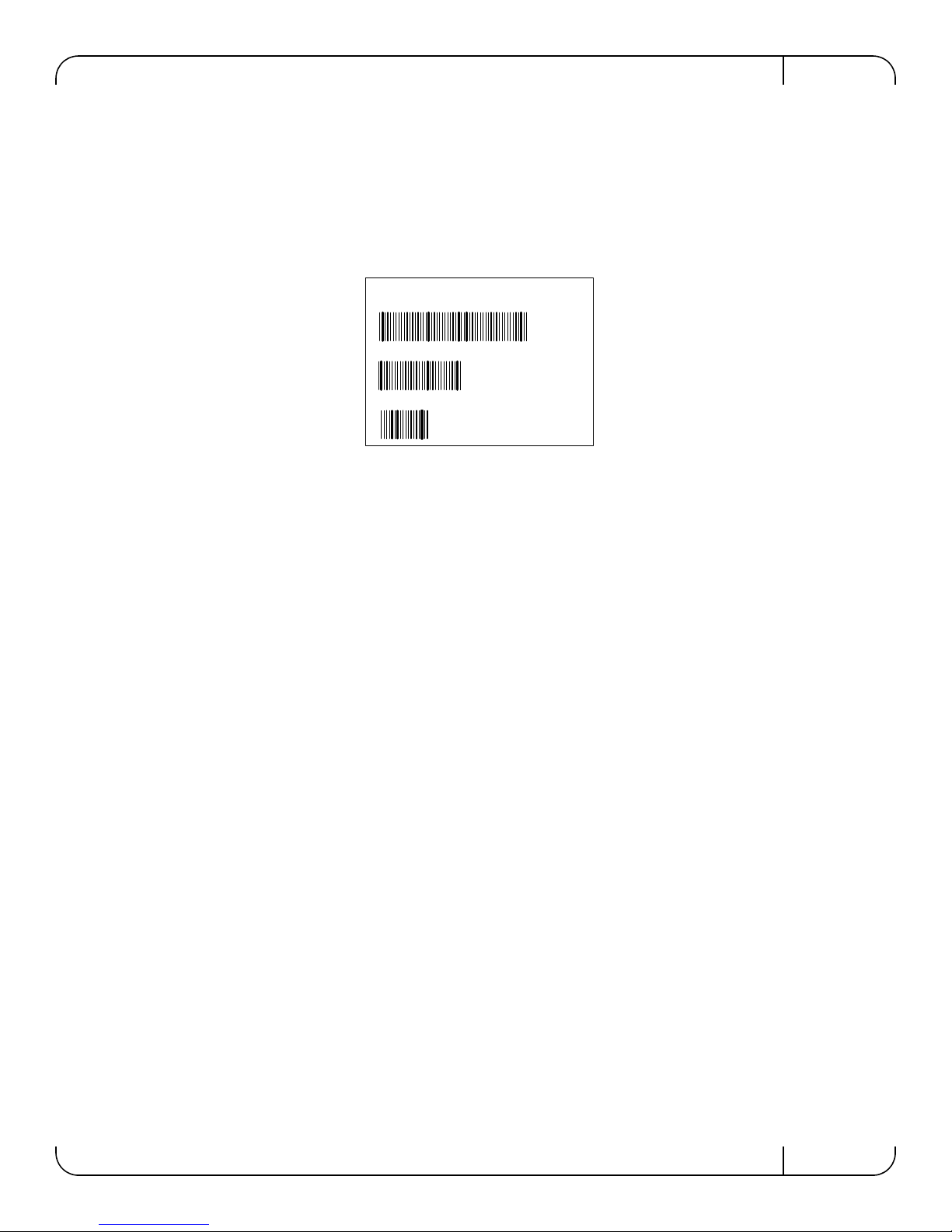
The serial number and product version information are found on the label seen in the figure below.
Figure 2: Generic Product label
7
Page 8
2 Installation and Basic Operation
Slot B1 Slot C1 Slot B2Slot C2
2.1 Unpacking the Pass Through Module
Before you install your new PTM, unpack it and make sure that there is no visible damage that
may have occurred during shipping. Your package should contain the following items:
• Dell -10GbE Pass Through Module for Blade Servers
• This User’s Manual
The PTM is shipped without optical modules.
If anything in the package is damaged or missing, please contact your customer representative
immediately.
2.2 Insertion and Removal of the PTM
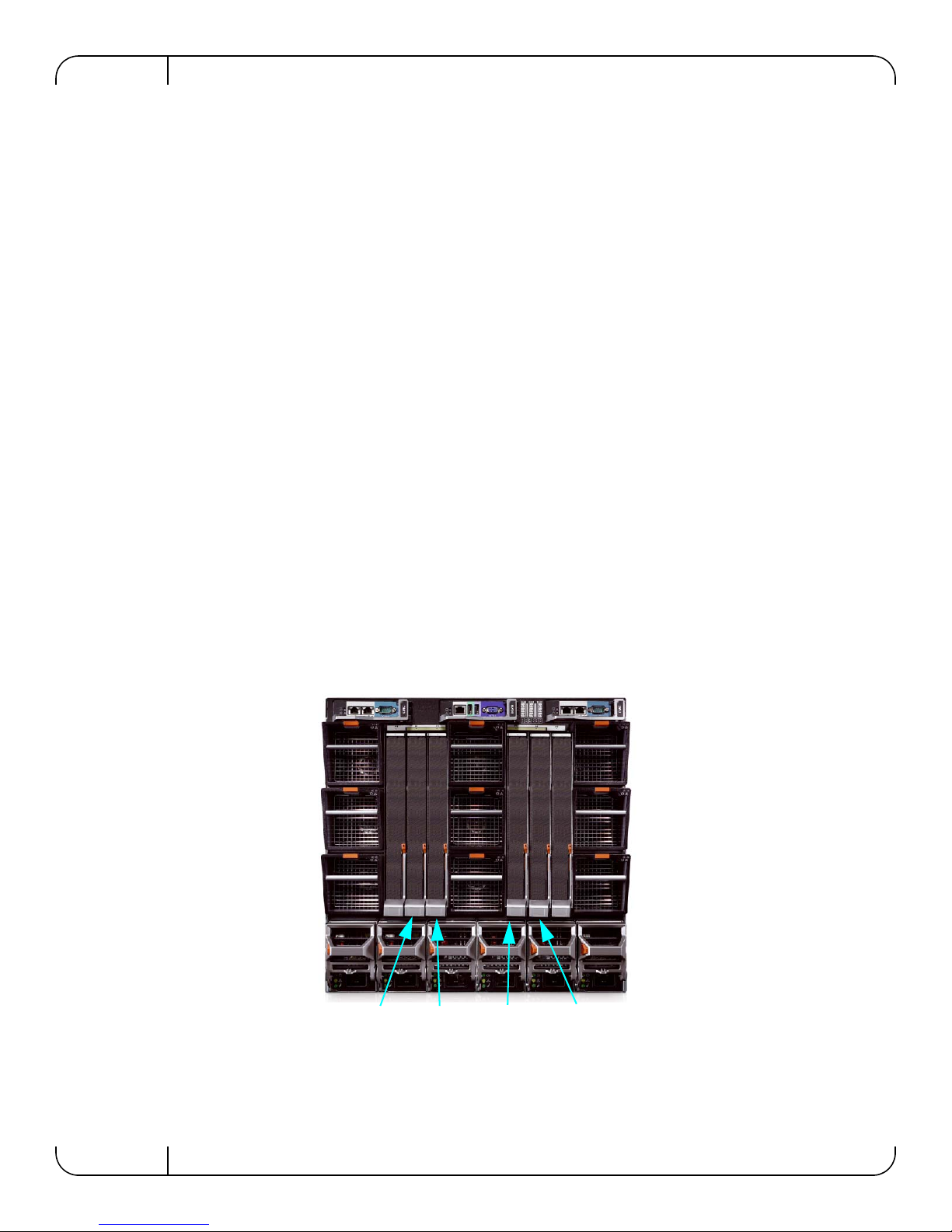
The Dell 10Gb Ethernet Pass Through II may be plugged into fabric slots B1, B2, C1, and C2.
Installation and Basic OperationRev 1.0
Determine which slot to use, based on desired system configuration.
2.2.1 PTM Insertion
Insert the PTM into the chassis as shown in the following diagram:
Figure 3: Dell Chassis Slots for the PTM
8
Page 9
Dell -10GbE PTM Rev 1.0
9
10
11
12
13
14
15
16
1
2
3
4
5
6
7
8
D
D
D
10 Gb Ethernet Pass Through II
The PTM supports hot-insertion into the chassis. If the PTM is inserted to a powered chassis, the
power LED (green) should turn on immediately.
2.2.2 PTM Removal
The PTM supports hot-removal. It may be removed when the chassis is powered on or off.
The PTM must not be removed during a firmware update process.
Note: Firmware update is in progress when the amber LED is blinking.
2.3 Connecting the External Ports
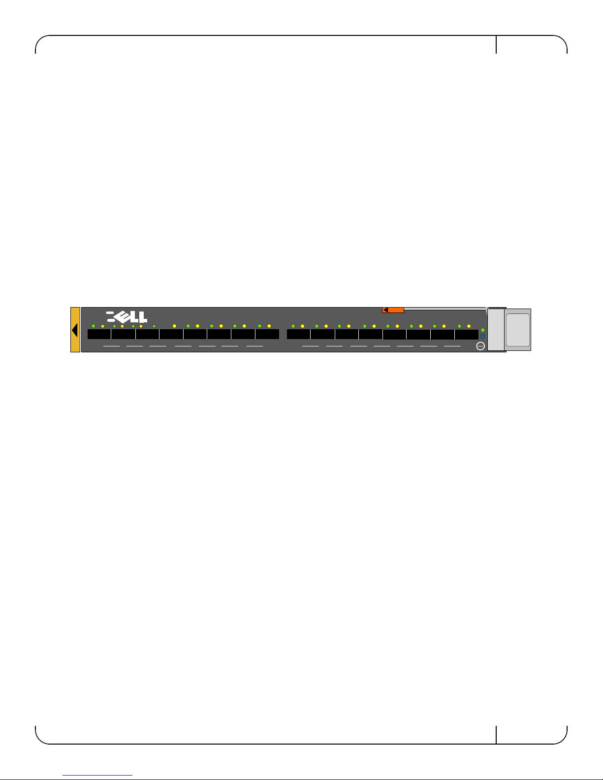
The PTM front panel presents 16 SFP+ ports. Each port provides connectivity to a server with the
respective number. Figure 4 shows the front panel view of the PTM.
Figure 4: Pass Through II Front Panel
2.3.1 10 Gigabit Ethernet SFP+ Modules
The PTM supports SFP+ modules for 10 Gigabit Ethernet, with 10GBASE-SR and 10GBASE-LR
PHYs. SFP+ modules must be approved for use with this PTM. Modules not approved may not
work. See Supported Optical Modules and DCAs on page 17 for lists of approved DCAs and optical modules.
2.3.2 Installation and Removal of Optical Transceiver Modules
Optical transceiver modules have a locking mechanism which can be opened or closed.
To insert the module into the cage:
1. Open the module’s locking mechanism.
2. Make sure that the male connectors on the module aligns with the female connector inside of
the cage. Also check that there is no dirt or foreign matter in the module or in the cage.
3. Insert the module into the adapter card module cage.
4. Close the locking Mechanism.
To remove the module from the cage:
1. Unlock the locking mechanism by opening the handle.
2. Pull the module out of the cage.
9
Page 10
2.4 LED Indicators
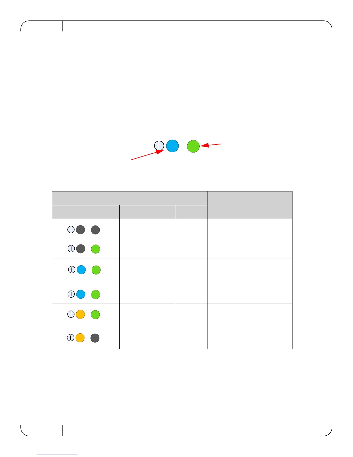
The IO Module is on and
ready when this LED is
green.
This LED can be blue or
amber. A fault is indicated
when the amber LED is blinking. See Table 3.
2.4.1 System LEDs
The system status LEDs indicate whether the PTM is receiving power from the chassis, and the
state of the PTM.
There are two system LEDs on the end of the module. The LED indications and meanings are
explained in the figure and table below.
Table 3 - PTM states and LED configurations:
Installation and Basic OperationRev 1.0
Figure 5: Indicator LEDs
LED
Indication Status Power
OFF OFF OFF
OFF ON Boot in Progress
BLINKING BLUE ON The CMC is identifying
Blinking Blue
ON BLUE ON PTM is on and operating Normally
ON or BLINKING
AMBER
ON or BLINKING
AMBER
Module Status
PTM not ready
the newly installed PTM
ON FW update is in progress or
Fault in System
Self-diagnosed
OFF Fault in System
CMC-detected
2.4.2 Port LEDs
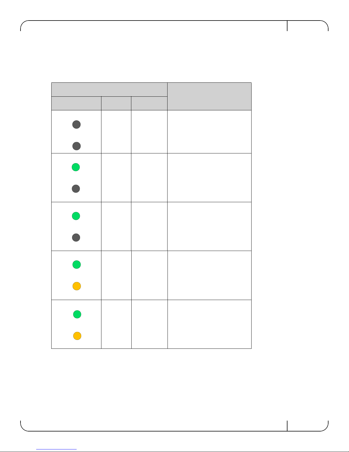
The PTM has two I/O LEDs per port. The I/O LEDs are located on the I/O panel. The green LED,
when lit, indicates that the driver is running and a valid physical connection between nodes exists.
If the green LED is blinking, it indicates a problem with the physical link. The yellow LED when
lit, indicates a valid data activity link, this is the logical link. The yellow LED illuminates when the
network is discovered over the physical link. A valid data activity link without data transfer is des-
10
Page 11
Dell -10GbE PTM Rev 1.0
ignated by a constant yellow LED indication. A valid data activity link with data transfer is designated by a blinking yellow LED indication. If the LEDs are not active, either the physical link or
the logical link (or both) connections have not been established.
Figure 6: Physical and Logical Link Indications
LED
Port Status
Indication Green
OFF OFF OFF
ON OFF Physical link up
Amber
No logical link
BLINKING OFF Problem with the physical link
No logical link
ON ON Physical link up
Logical link up, no data transfer
ON BLINKING Physical link up
Logical link up, with data transfer
11
Page 12
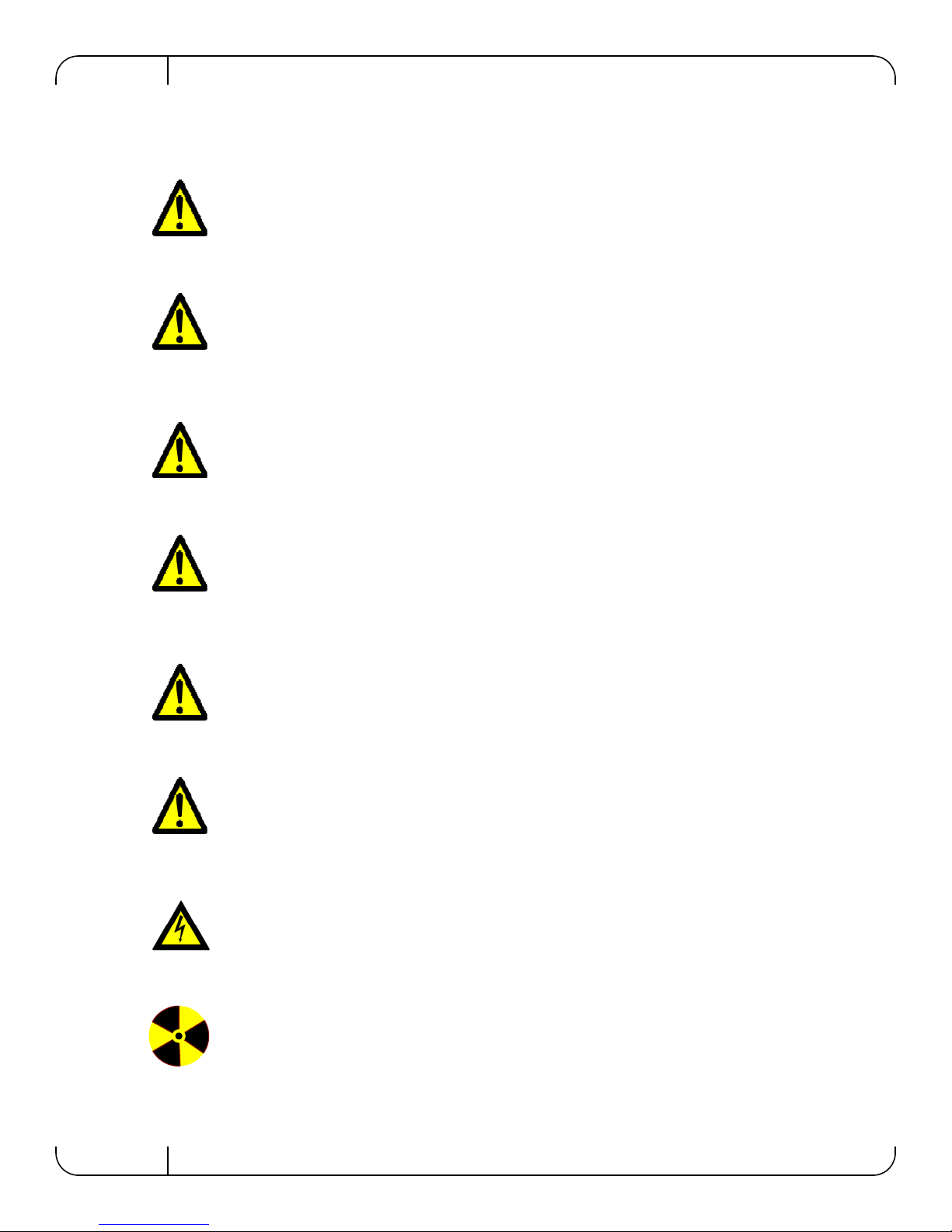
2.4.3 Installation Safety Warnings
1. Installation Instructions
Read all installation instructions before connecting the equipment to the power source.
2. Over-temperature
This equipment should not be operated in an area with an ambient temperature exceeding the maximum recommended: 40°C
(104°F). An air flow of 9CFM at this maximum ambient temperature is required.
3. During Lightning - Electrical Hazard
During periods of lightning activity, do not work on the equipment or connect or disconnect cables.
4. Copper Direct Attached SFP+ Cable Connecting/Disconnecting
Installation and Basic OperationRev 1.0
Copper Direct Attached SFP+ cables are heavy and not flexible,
as such they should be carefully attached to or detached from the
connectors. Refer to the cable manufacturer for special warnings
and instructions.
5. Equipment Installation
This equipment should be installed, replaced, or serviced only
by trained and qualified personnel.
6. Equipment Disposal
Disposal of this equipment should be in accordance to all
national laws and regulations.
7. Local and National Electrical Codes
This equipment should be installed in compliance with local and
national electrical codes.
8. Hazardous Radiation Exposure
Caution – Use of controls or adjustment or performance of procedures
other than those specified herein may result in hazardous radiation
exposure.
12
Page 13
Dell -10GbE PTM Rev 1.0
CLASS 1 LASER PRODUCT and reference to the most recent laser
standards:
IEC 60825-1:2007/03 y EN 60825-1:2007
2.4.4 Mechanical Installation
2.4.4.1 To install the PTM
1. Make sure that there is no foreign matter or dirt in the back plane connector or in the chassis slot.
2. Push the PTM into the chassis. Make sure that the ears on the latch hook onto the latching bar.
3. Push the latch handle towards the orange latch release until it locks.
2.4.4.2 To remove the PTM
1. Push the orange latch release and the latch handle will pop out
2. Pull the handle out until it is 90 degrees from the front of the PTM.
3. Pull the PTM out of the chassis.
2.4.5 Cable Installation
All cables can be inserted or removed with the unit powered on. To insert a cable, press the connector into the port receptacle until the connector is firmly seated. The GREEN LED indicator,
above each SFP+ port, will light when the physical connection is established (that is, when the unit
is powered on and a cable is plugged into the port with the other end of the connector plugged into
a functioning port). After plugging in a cable, lock the connector using the latching mechanism
particular to the cable vendor. When a logical connection is made the yellow light will come on.
When data is being transferred the yellow light will blink.
Always install and remove cables by pushing or pulling the cable and
connector in a straight line with the pass through module.
To remove, disengage the locks and slowly pull the connector away from the port receptacle. Both
LED indicators will turn off when the cable is unseated.
Cable lengths should be used which allow for routing horizontally around to the side of the chassis
before bending upward or downward in the rack.
Cables, especially long copper cables, can weigh a substantial amount.
Make sure that the weight of the cable is supported on its own and not
hanging from the pass through module.
13
Page 14

3 Troubleshooting
As soon as a pass through module is plugged in make sure that the status LED shows green.
The power LED for the pass through module shuts off:
1. Check that the there is adequate ventilation.
2. Make sure that there is nothing blocking the front or rear of the chassis and that the fan modules and ventilation holes are not blocked (especially dust over the holes).
3. If you find dust blocking the holes it is recommended to clean the fan unit and remove the dust
from the front and rear panels of the pass through module using a vacuum cleaner.
4. Remove and Reinstall the PTM.
TroubleshootingRev 1.0
14
Page 15
Dell -10GbE PTM Rev 1.0
Appendix A: Specifications
Table 4 - Dell 10Gb Ethernet Pass Through Module Specification Data
Physical Power and Environmental
Size:
W X D X H
Weight:
SerDes Speeds:
Connectors and
Cabling:
Optical Cable:
Port Types:
Air Flow:
Protocol Support Regulatory Compliance
Ethernet:
Blade Servers to
PTM (Internal
Links):
Front Panel Ports
(External Links):
24.7 cm X 28.5 cm X 2.9 cm
1.978kg
10, Gb/s per port
SFP+
Direct attached copper cables supported
Optical cables supported
SFP+
3CFM @ 30
9CFM @ 40
IEEE 802.3ae 10Gigabit Ethernet
support
IEEE 802.3ap Ethernet Operation
over Electrical Backplanes
XAUI
10G XFI
8 Priority Queues for Ethernet
QoS:
o
C ambient temperature
o
C ambient temperature
Maximum
Power:
Typ Power:
Temperature:
Humidity:
Altitude:
Shock:
Vibration:
Power through
SFP+:
Safety:
EMC
(Emissions):
40.55W passive cables
53.73W active cables
34.41W passive cables
50.59W active cables
0° to 40° Celsius
10% - 90% non-condensing
max 1W per port
UL60950
C-UL to CAN/CSA 22 2
No.60950-1
TUV/GS to EN 60950-1,
Amendment A1-A4, A11
CB-IEC60950-1, all country deviations
CC 47CFR Part 15 Class A
EN 55022 Class A
ICES-003 Class A
VCCI Class A
AS/NZS CISPR 22 Class A
CISPR 22 Class A
EN 55024
EN 300386
CE
Environmental:
EU: IEC 60068-2-64: Random Vibration
EU: IEC 60068-2-29:
Shocks, Type I / II
EU: IEC 60068-2-32: Fall
Test
15
Page 16
Rev 1.0
23.023.0
24.7
2.9
5.5
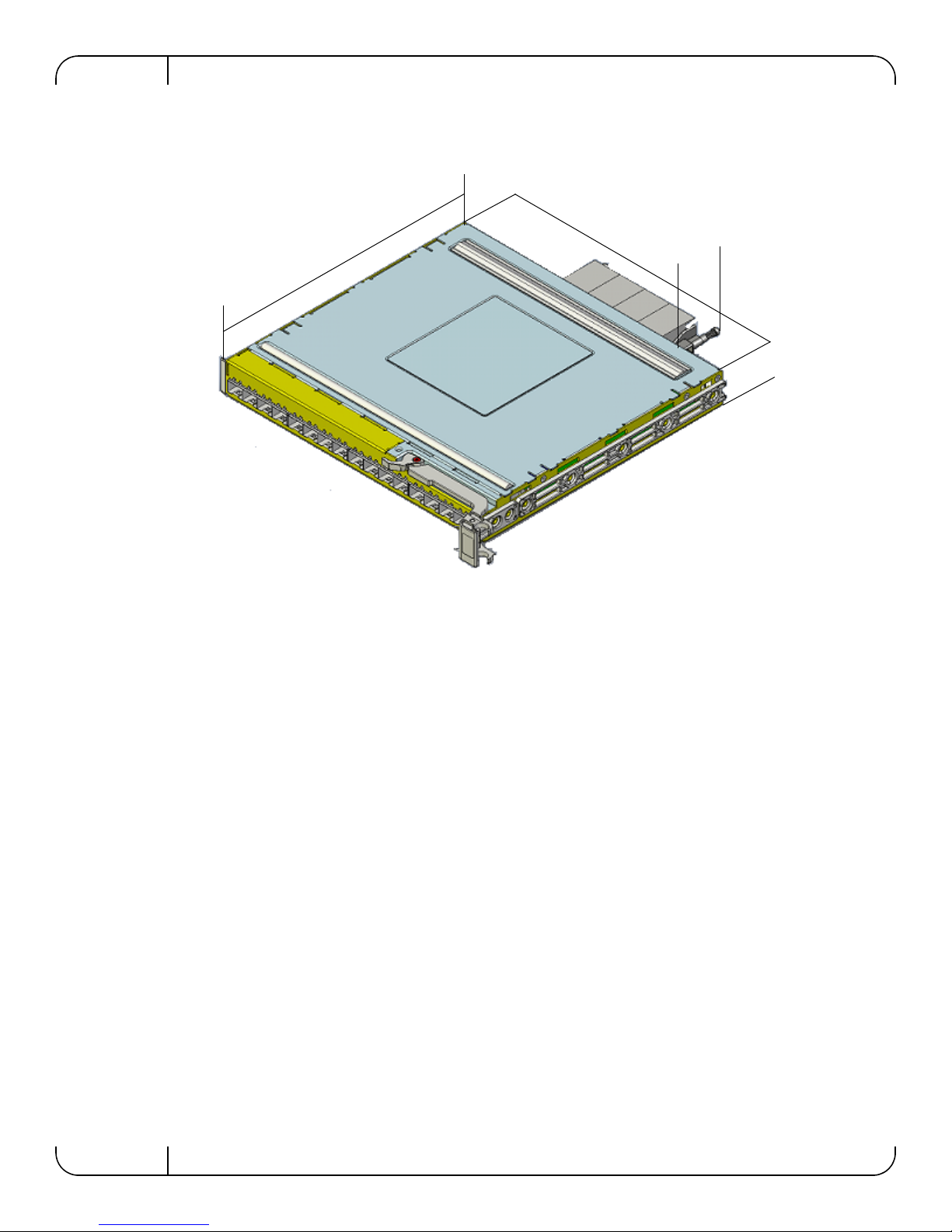
Appendix A.1: Mechanical Drawing with Dimensions
Figure 7: Mechanical Drawing
16
Page 17
Dell -10GbE PTM Rev 1.0
Appendix B: Supported Optical Modules and DCAs
The following cables and optical modules are approved for the Dell PTM
Table 5 - DCA (Direct attached SFP+ cables)
DPN Reference Length (m) Speed Molex Custom PN
K585N SFP-H10GB-CU1M 1 10.3125Gbps 74752-9093
J564N SFP-H10GB-CU3M 3 10.3125Gbps 74752-9094
H603N SFP-H10GB-CU5M 5 10.3125Gbps 74752-9096
G840N SFP-H10GB-CU7M 7 10.3125Gbps 74752-9098
R620M 30 AWG 0.5 10.3125Gbps 74752-1051
G692K 30 AWG 1 10.3125Gbps 74752-1101
P540M 30 AWG 2 10.3125Gbps 74752-1201
Y984J 28 AWG 3 10.3125Gbps 74752-2301
N651M 28 AWG 4 10.3125Gbps 74752-2401
C855K 28 AWG 5 10.3125Gbps 74752-3501
Table 6 - Optical Modules
DPN Reference Speed Manufacturer
N743D ASSY,XCVR,SFP+,LC-LC,SFP+SR 10.3125Gbps Finisar
T307D ASSY,XCVR,SFP+,LC-LC,SFP+LR 10.3125Gbps Finisar
W365M ASSY,XCVR,SFP+,LC-LC,SFP+SR,AV 10.3125Gbps Avavgo
W373M ASSY,XCVR,SFP+,LC-LC,SFP+LR,AV 10.3125Gbps Avavgo
17
Page 18
Rev 1.0
Warning
This is a class A product. In a domestic environment this product may cause
radio interference in which case the user may be required to take adequate
Appendix C: EMC Certification Statements
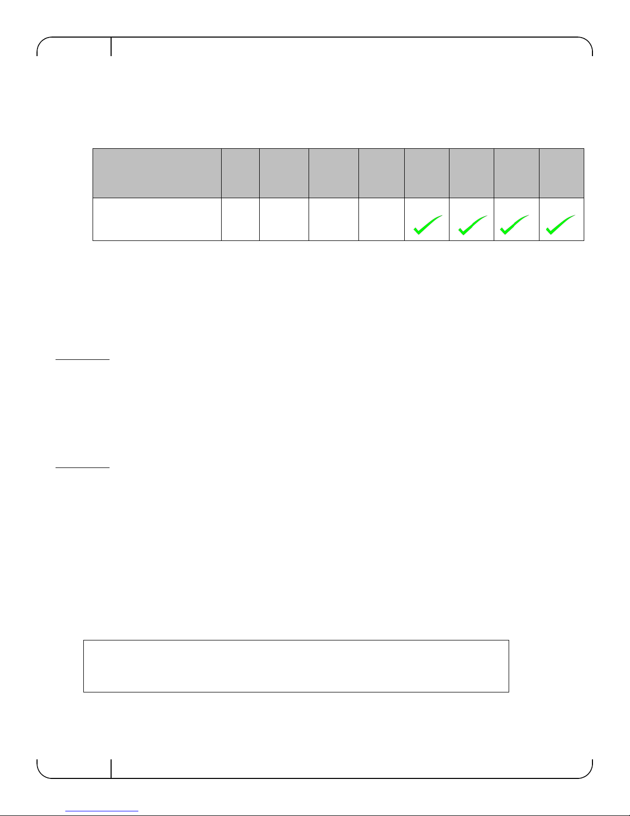
Table 7 lists the approved certification status per bridge in different regions of the world.
Table 7 - Bridge Certification Status
FCC
Pass through Module P/N
M1601P series A A A A
Class
(USA)
EN
Class
(Europe)
Appendix C.1: FCC Statements (USA)
Class A Statements:
§ 15.21
Statement
Warning! Changes or modifications to this equipment not expressly approved by the party
responsible for compliance could void the user's authority to operate the equipment.
§15.105(a)
ICES
Class
(Canada)
VCCI
(Japan)
cTUVus KCC CB c-Tick
Statement
NOTE: This equipment has been tested and found to comply with the limits for a Class A digital
device, pursuant to Part 15 of the FCC Rules. These limits are designed to provide reasonable protection against harmful interference when the equipment is operated in a commercial environment.
This equipment generates, uses, and can radiate radio frequency energy and, if not installed and
used in accordance with the instruction manual, may cause harmful interference to radio communications. Operation of this equipment in a residential area is likely to cause harmful interference
in which case the user will be required to correct the interference at his own expense.
Appendix C.1.1: EN Statements (Europe)
EN55022 Class A Statement:
18
Page 19
Dell -10GbE PTM Rev 1.0
Appendix C.2: ICES Statements (Canada)
Class A Statement:
“This Class A digital apparatus complies with Canadian ICES-003.
Cet appareil numérique de la classe A est conforme à la norme NMB-003 du Canada.”
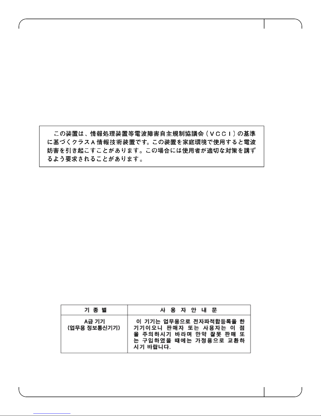
Appendix C.3: VCCI Statements (Japan)
Class A Statement:
Appendix C.3.1: T ranslation
"This is a Class A product based on the standard of the Voluntary Control Council for Interference
by Information Technology Equipment (VCCI). If this equipment is used in a domestic environment, radio interference may occur, in which case the user may be required to take corrective
actions."
Appendix C.4: KCC Certification (Korea)
Korea's "Regulation for Certification of Information and Communication Equipment," requires
EMC testing and certification for many electronic products. Korean EMC certifications are issued
by Radio Research Laboratory (RRL), which is organized under the Ministry of Information and
Communications (MIC). EMC testing includes electromagnetic emissions (EMI) and susceptibility (EMS). Certified equipment is labeled with the MIC mark and certification number.
19
Page 20

Rev 1.0
Appendix C.4.1: T ranslation:
“Class A Device This device is registered for EMC requirements for industrial use. The seller or
buyer should be aware of this. If this type was sold or purchased by mistake, it should be replaced
with a residential-use type. “
20
Page 21

Dell -10GbE PTM Rev 1.0
VeeT
VeeT
VeeT
TX_Fault
TX_Disable
SDA
SCL
MOD_ABS
RS0
RX_LOS
RS1
VeeR
VeeR
VeeR
VccT
VccR
TD+
TD-
RD-
RD+
1
2
3
4
5
6
7
8
9
1
2
3
4
5
6
7
8
9
0
1
1
1
1
1
1
1
1
1
2
10
Appendix D: Interface Connector Pinouts
Appendix D.1: SFP+ Interface
Figure 8: SFP+ Connector Pinout - Rear View of Module With Pin Placement
Table 8 - SFP+ Pinout
Pin Symbol Name Description
1 VeeT
2 TX_Fault
3 TX_Disable
4 SDA
5 SCL
6 MOD_ABS
Transmitter Ground (Common with Receiver Ground)
Transmitter Fault.
b
Transmitter Disable. Laser output disabled on high or open.
2-wire Serial Interface Data Line
2-wire Serial Interface Clock Line
Module Absent. Grounded within the module
7 RS0 No connection required
8 RX_LOS
Loss of Signal indication. Logic 0 indicates normal operation.
9 RS1 No connection required
10 VeeR
11 VeeR
Receiver Ground (Common with Transmitter Ground)
Receiver Ground (Common with Transmitter Ground)
a
c
d
d
d
e
a
a
12 RD- Receiver Inverted DATA out. AC Coupled
13 RD+ Receiver Non-inverted DATA out. AC Coupled
14 VeeR
Receiver Ground (Common with Transmitter Ground)
a
21
Page 22
Rev 1.0
Table 8 - SFP+ Pinout
Pin Symbol Name Description
15 VccR Receiver Power Supply
16 VccT Transmitter Power Supply
17 VeeT
Transmitter Ground (Common with Receiver Ground)
18 TD+ Transmitter Non-Inverted DATA in. AC Coupled.
19 TD- Transmitter Inverted DATA in. AC Coupled.
20 VeeT
a. Circuit ground is internally isolated from chassis ground.
b. T
Ohms resistor on the host board if intended for use. Pull up voltage should be between 2.0V
to Vcc + 0.3V. A high output indicates a transmitter fault caused by either the TX bias current or the TX output power exceeding the preset alarm thresholds. A low output indicates
normal operation. In the low state, the output is pulled to <0.8V.
c. Laser output disabled on TDIS >2.0V or open, enabled on TDIS <0.8V
d. Should be pulled up with 4.7kΩ – 10kΩ on host board to a voltage between 2.0V and 3.6V.
MOD_ABS pulls line low to indicate module is plugged in.
e. LOS is open collector output. Should be pulled up with 4.7kΩ – 10kΩ on host board to a
voltage between 2.0V and 3.6V. Logic 0 indicates normal operation; logic 1 indicates loss of
signal.
is an open collector/drain output, which should be pulled up with a 4.7k – 10k
FAULT
Transmitter Ground (Common with Receiver Ground)
a
a
22
 Loading...