

Page 1
T5, T14D, T40
Blast Chiller/Shock Freezers
Original Instructions
Installation, Operation and Maintenance Manual
This manual is updated as new information and models are released. Visit our website for the latest manual.
Part Number: DMCONVOCHILL 12/17
Page 2

Important Warning And Safety Information
WARNING Read This Manual Thoroughly Before Operating, Installing, Or Performing Maintenance On The Equipment.
WARNING Failure To Follow Instructions In This Manual Can Cause Property Damage, Injury Or Death.
WARNING Do Not Store Or Use Gasoline Or Other Flammable Vapors Or Liquids In The Vicinity Of This Or Any Other
Appliance.
WARNING Unless All Cover And Access Panels Are In Place And Properly Secured, Do Not Operate This Equipment.
WARNING This Appliance Is Not Intended For Use By Persons Who Lack Experience Or Knowledge, Unless They Have
Been Given Supervision Or Instruction Concerning Use Of The Appliance By A Person Responsible For
Their Safety.
WARNING This Appliance Is Not To Be Played With.
WARNING Do Not Clean With Water Jet.
WARNING Do Not Use Electrical Appliances Inside The Food Storage Compartment Of This Appliance.
CAUTION Observe the following:
• Minimum clearances must be maintained from all walls and combustible materials.
• Keep the equipment area free and clear of combustible material.
• Allow adequate clearance for air openings.
• Operate equipment only on the type of electricity indicated on the specification plate.
• Unplug the unit before making any repairs.
• Retain this manual for future reference.
WARRANTY INFORMATION
Visit http://www.delfield.com/warranty to:
• Register your product for warranty.
• Verify warranty information.
• View and download a copy of your warranty.
2
Page 3

CONTENTS
1. GENERAL DOCUMENTATION
1.1 General information 4
1.2 Installation 4
1.3 Transport and handling 4
1.4 Unpacking 4
1.5 General safety regulations 4
2. INSTALLATION
2.1 Data plate information 5
2.2 Positioning 5
2.3 Ambient temperature and air circulation 5
2.4 Electrical connections 5
2.6 Condensate drainage connection 6
2.7 Information for the installation technician 6
2.8 Safety and control systems 6
2.9 Appliance disposal 6
2.10 Door Hinge Reversal Procedure 7-10
6. APPLIANCE FUNCTIONS
6.1 Date and time settings 20
6.2 Ice cream surface hardening 20
6.3 Muting the beeper and alarm reset 20
6.4 Program storage 20
6.5 Displaying the three latest HACCP alarms 21
6.6 Forced ventilation function 21
6.7 Manual defrosting 21
6.8 Automatic defrost cycles 21
6.9 USB Data Recorder Operation 22
7. ALARM MANAGEMENT
7.1 Storage of data/errors 23
7.2 Alarms list 23-26
8. MAINTENANCE AND CLEANING
8.1 General safety regulations 27
3. ADVICE TO ENSURE EFFICIENT APPLIANCE
OPERATION
3.1 Shut-down procedures 11
3.2 Operating tips 11
3.2.1 Precooling 11
3.2.2 Loading the appliance 11
4. DESCRIPTION OF THE CONTROL PANEL 12
4.1 Push-buttons 13
5. PROGRAMMING AND OPERATING
INSTRUCTIONS
5.1 Starting up the appliance 14
5.2 Soft blast chilling by temperature 15
5.3 Soft timed blast chilling 16
Hard blast chilling 16
8.2 Cleaning the condenser 27
8.3 Cleaning the internal room 27
8.4 Defrost water drainage 27
9. BLAST CHILLER AND REMOTE CONDENSER
SPECS 28-31
10. T5/T14D REFRIGERATION SYSTEM
SCHEMATIC 32
11. WIRING DIAGRAMS 33-35
12. T40 ASSEMBLY INSTRUCTIONS 36-39
5.4 Hard blast chilling by temperature 17
5.5 Hard timed blast chilling 17
5.6 Blast freezing by temperature 18
5.7 Timed blast freezing 19
3
Page 4
1. GENERAL DOCUMENTATION
1.1. General information
• This manual is an integral part of the product,
providing all the information required to ensure
correct installation, operation and maintenance
of the machine.
• Read the manual carefully, making reference
to it for machine operation. Keep the manual
in a safe place where it can be accessed by all
authorized operators (installers, operators and
service personnel).
• The machine has been designed for professional
applications only and should only be operated
by qualied personnel.
• The machine must only be used for the purposes
for which it was designed, i.e. for chilling and
freezing food products.
The machine must not be used for products
requiring constant temperature control and
recording, such as:
- heat-sensitive chemicals,
- medicines or
- blood products.
• The manufacturer declines all responsibility
for any damage caused by incorrect or
unreasonable machine use, such as:
• improper use by untrained persons;
• technical modications or operations not suited
to specic models;
• use of non-original or non-specic spare parts;
• failure to follow the instructions given in this
manual.
1.2 Installation
In the event that the machine is tted with
a remote condenser unit, the installation
technician is responsible for checking all
connections in compliance with the instructions
given by Deleld for plant and machine
installation.
1.3 Transport and handling
• To load or unload the machine and/or
components from/onto the means of transport,
use a lift truck or fork lift equipped with forks
that are at least half the length of the machine
housing; use a crane if the machine is tted with
eye bolts. Select the lifting equipment suited
to the weight and overall dimensions of the
packaged machine/components.
• When handling the machine/ components,
apply all precautions to prevent damage, in
compliance with the information given on the
packaging material
1.4 Unpacking
• Remove all cardboard, wood or other materials
from the wood base on which the machine is
set. Lift the machine/components with suitable
means (e.g. lift truck), remove the wood base,
then position the machine/components in the
allocated site.
• Once all packing material has been removed,
check that the machine has
not been damaged in any
way.
• Remove the protective
PVC lm on the stainless
steel panels from all
internal and external
surfaces (g. 2).
• Always wear protective
gloves when handling packing material and the
wood base.
• Dispose of packing materials in compliance
with disposal regulations applied in the country
where the machine is to be installed. Never
dispose of materials in the environment.
1.5 General safety regulations
Failure to observe the recommendations made
by the present manual will be at the entire
responsibility of the machine user. The main
safety regulations are as follows:
- do not touch the machine with moist or wet
hands or feet;
- never operate the machine while barefoot;
- do not insert screwdrivers, cooking utensils
or any other object between the guards and
moving parts;
- before performing cleaning or routine
maintenance operations, disconnect the
machine from the power supply;
- never pull on the power cable to disconnect
the machine from the power supply.
4
Page 5

2. INSTALLATION
2.1 Data plate information
• Check that the data specied on the plate
corresponding to the characteristics of the
power supply (V, kW, Hz, phases and power
available).
• The dataplate with appliance specications
is located at the rear exterior of the machine
and/or on the electrical
boards (g. 3). The setup of individual units
and the installation of
condensers are subject to
the re-safety regulations
of the country in which the machine is installed;
seek all necessary advice from the local reghting authorities. Bear in mind that the
intervention of safety valves or plug fuses in the
refrigerating circuit will lead to the immediate
discharge of refrigerant into the environment.
2.2 Positioning
• The machine must be installed in complete
compliance with safety regulations, procedures
and standing laws.
• Position the machine in the allocated site.
• Adjust the machine feet by turning the foot
clockwise until the appliance is perfectly level.
In the case of particularly heavy equipment, use
appropriate lifting means.
(g. 4).
• If the appliance is not perfectly level, correct
operation and condensate ow-o will not be
assured.
AVOID
• direct exposure to sunlight;
• closed sites with high temperatures and poor air
circulation;
• installing the machine near sources of heat
Installation Clearance Requirements
All Cabinets:
12” clearance above top
12” clearance on sides and rear
Remote condensing units for T40 models.
24” clearance above top
6” clearance on sides and rear
2.3 Ambient temperature and air circulation
For air-cooled appliances, the maximum ambient
temperature for operation is 90°F / 32°C. Correct
operation cannot be guaranteed at higher
temperatures. The machine may operate safely
to a maximum temperature of 100°F / 38°C.
Remote condensing units may be installed
indoors next to the unit or within 25 ft. Consult
Deleld if placement will be greater than 25
ft. away. Remote condensing units may also
be installed outdoors but require a U.L. listed
enclosure which is supplied as an option from
Deleld. Sucient air circulation must be
guaranteed at all times.
2.4 Electrical connections
A dedicated thermal-magnetic circuit breaker
compliant with established regulations must be
installed on the appliance power line.
• Connected electrical cables must correspond
to the technical data (as specied on electrical
drawings provided by the installation
technician).
Connect the ground conductor to an ecient
ground system.
THE MANUFACTURER DECLINES ALL LIABILITY
AND GUARANTEE OBLIGATIONS IN THE EVENT
OF INJURY TO PERSONS OR DAMAGE TO
EQUIPMENT AND OBJECTS DUE TO INCORRECT
INSTALLATION AND/OR FAILURE TO COMPLY
WITH STANDING INSTALLATION REGULATIONS.
5
Page 6

2.6 Condensate drainage connection
For T40 models t a condensate water drainage
hose with a minimum diameter of 1” . Provide
a waste pipe with a trap with a diameter of at
least 1 1/2” at oor level.
2.7 T40 Information for the installation technician
Before starting up the machine, check that it has
been correctly installed.
1. Check that there are no gas leaks from brazed
joints made during installation.
2. Check that the pipes connecting the condenser
to the remote condensing unit have been well
insulated.
3. Check all wiring connections.
4. Check electrical input.
5. Check the standard pressure in the refrigerant
system.
6. Perform at least one blast freezing cycle (to the
SET temperature) and one manual defrosting
cycle. In the event that the appliance or
the remote condensing unit have not been
transported in a vertical position (e.g. on
the back) or have been overturned during
installation works, allow at least 4 hours before
starting up the equipment.
2.8 Safety and control systems
• Door microswitch: shuts down fan operation in
the cabinet when the door is opened.
• General fuses: protect the power circuit against
short circuiting and overloads.
• Compressor heat relay: intervenes in the event
of overloads or operating faults.
• Safety pressure switch: intervenes in the event of
excessive pressure in the refrigerant circuit.
• Plug fuses: intervene in the event of high
pressure or operating fault in the safety pressure
switch (see above).
• Chamber temperature control: operated by the
electronic board by means of a probe inside the
cabinet.
• Temperature control end defrost cycle:
controlled by the electronic board by means of
the probe in the evaporator.
2.9 Appliance disposal
After the useful life of the appliance has been
realized, be sure to demolish and dispose of the
machine in compliance with the regulations
applied in the country of installation,
particularly in regards to refrigerant gas and
compressor lubricant oil.
6
Page 7

T5/T14D DELFIELD PROCEDURA PER LA ROTAZIONE DELLA PORTA
DOOR ROTATION PROCEDURE
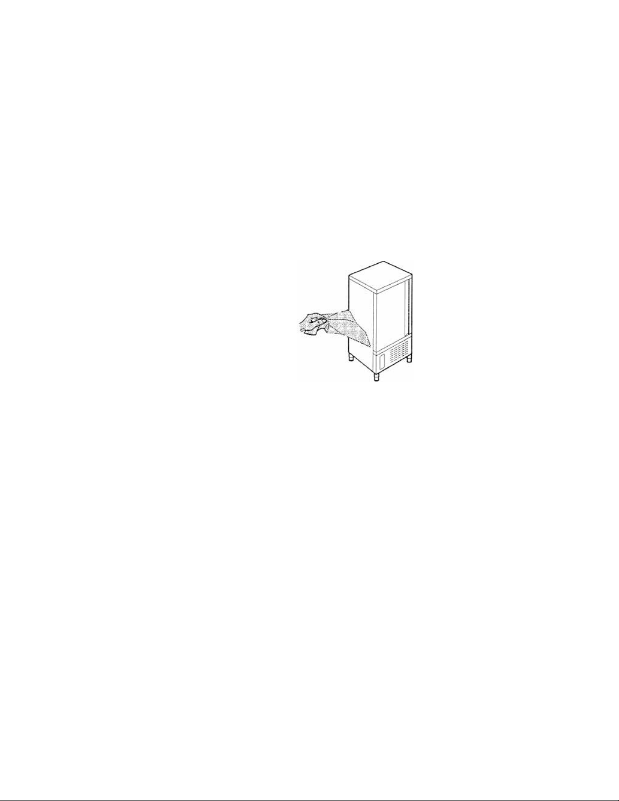
1.Rimuovere la presa d’aria frontale svitando le 4 viti delle cerniere lato inferiore
1. Remove 4 bolts from the air intake panel bottom edge.
Remove the air front intake panel unscrewing the 4 screws of inferior hinge
2.Aprire la presa d’aria frontale facendo leva con un cacciavite su entrambi i lati
2. Open the air intake panel using the lever as a screwdriver on both sides.
Open the air intake panel making a lever with a screwdriver on both sides
2.10 Door Hinge Reversal Procedure
3.Scollegare il connettore dalla scheda pulsanti Remove the connector from the push buttons card
3. Disconnect the data cables.
4. Remove the two lower hinge bolts.
4.Svitare le 2 viti che fissano la cerniera inferiore
Unscrew the 2 bolts that fix the inferior hinge
7
Page 8
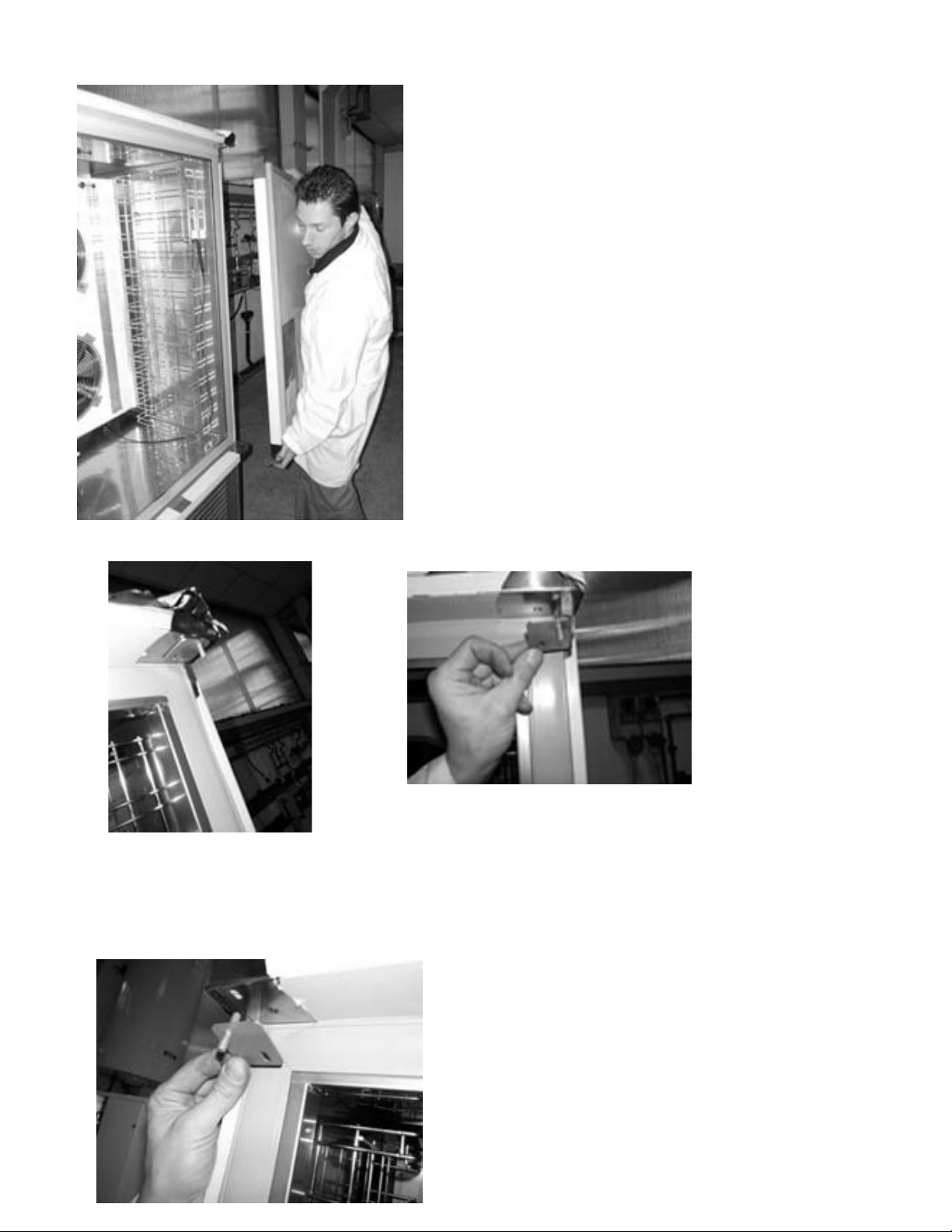
5.Rimuovere la porta dell’abbattitore Remove the chiller door
5. Remove the chiller door.
6. Remove the right top hinge. Rotate it 180º and install it on the left top side of the chiller.
6.Rimuovere la cerniera superiore destra ruotarla di 180° ed
installarla sul lato sinistro dell’abbattitore
Remove the right top hinge and rotate it of
180° and provide to install it on the left top
side of chiller
8
Page 9
Lower right
Cerniera inferiore destra Cerniera inferiore sinistra(in
hinge
Lower right hinge Lower left hinge
Lower left hinge
(left hinge
dotazione)
supplied as
(left hinge as accessory)
accessory)
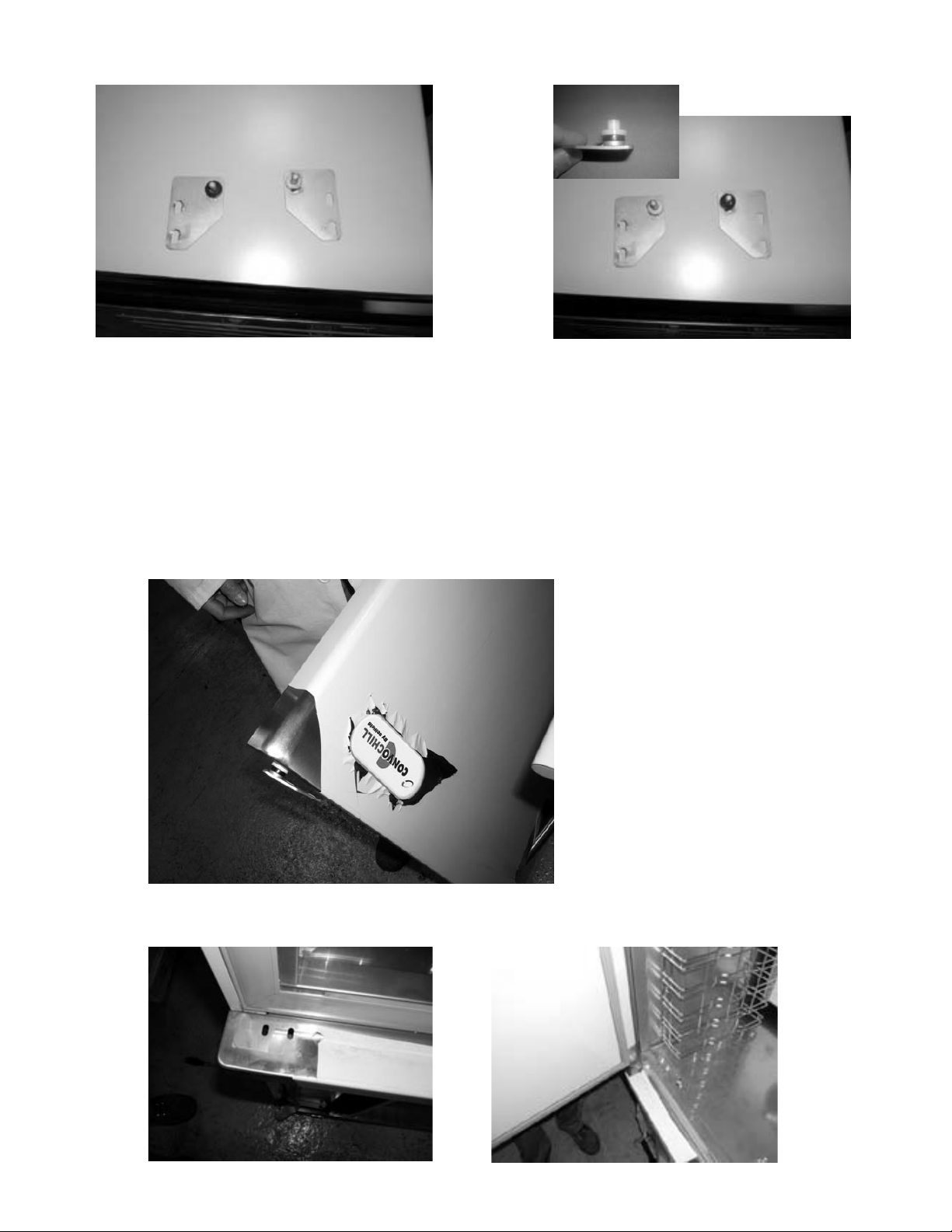
7. Move the black washer and the
plastic bushing from the right hinge
to the left hinge.
7.Spostare la guarnizione
nera e la boccola in
plastica dalla cerniera
destra su quella sinistra
Move the black gasket
and the plastic buckle
from the right hinge to
the left hinge.
8.Ruotare la porta di 180° ed installare la cerniera inferiore
8. Rotate the door 180º and insert the lower left hinge.
Sinistra. Rotate the door of 180° and install the inferior left hinge .
9.Installare la porta fissando la cerniera inferiore sinistra negli appositi fori predisposti
9. Install the door, inserting the top hinge into the prepunched holes, aligning the left
Install the door fixing the left inferior hinge in the predisposed holes
lower hinge with the prepunched holes.
9
Page 10
10.Fissare la porta effettuando la regolazione delle cerniere in modo da garantire una corretta
10. Adjust the door and door hinges to guarantee a correct closing and sealing of the gasket. Install the
chiusura ed aderenza della guarnizione porta.
two lower hinge bolts.
Successivamente bloccare definitivamente le 2 cerniere.
Reinstallare la targhetta adesiva sul frontale della porta e reinstallare la presa d’aria seguendo le
11. Use a putty knife or similar tool to peel o the adhesive nameplate. Rotate, and reattach the nameplate.
istruzioni.
12. Reconnect the data cables.
Attenzione:
13. Reinstall the front air intake panel.
il micro della porta funziona se allineato al magnete schiumato all’interno della stessa.
In caso di allarme porta aperta regolare la posizione della porta e/o micro.(vedi ultime foto)
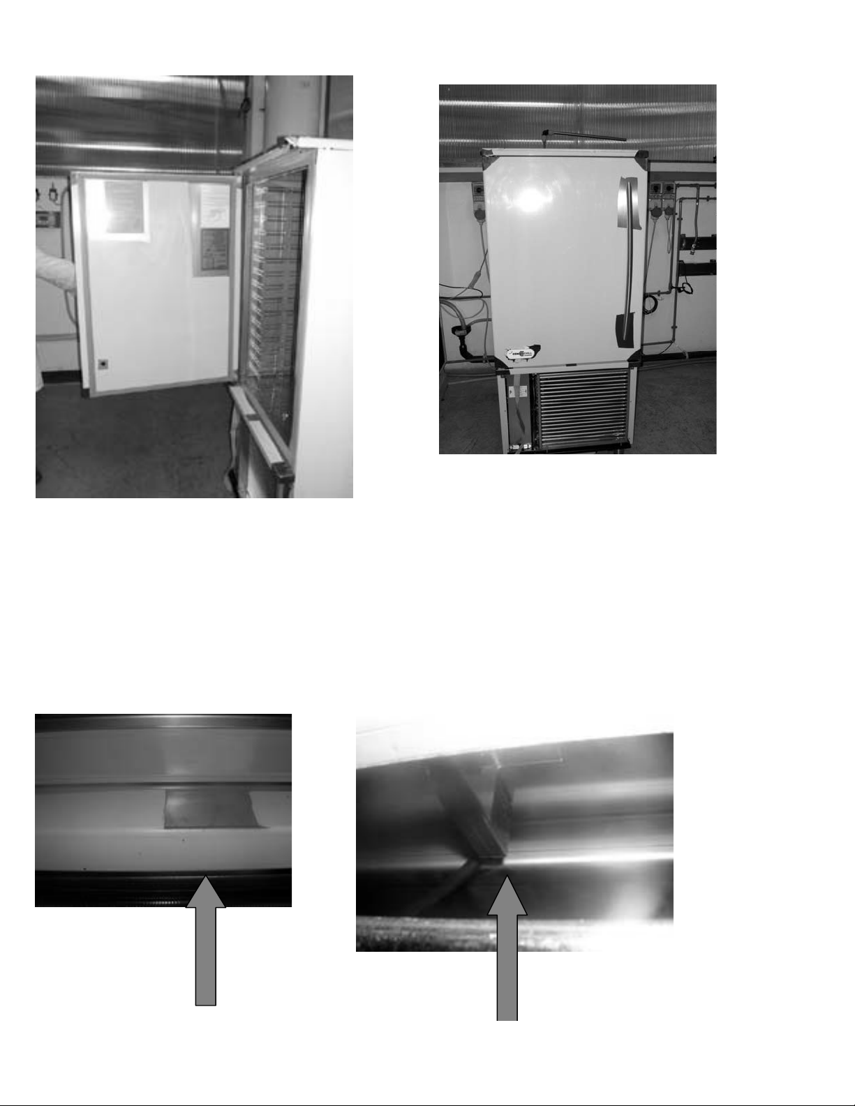
Attention: The door micro switch works if it’s aligned to the magnet positioned inside the door. In case the
door alarms, adjust the door and/or the micro switch position. See pictures below.
Fix the door doing the hinges regulation so that to guarantee a correct closing and adherence of
the gasket .
Subsequently fix and stop definitely the 2 screws.
Install the adhesive nameplate on the door façade and proceed to reinstall the front air intake
panel following the previous instruction.
Attention:
the door micro switch works if it’s aligned to the magnet positioned inside the door.
In case of door alarm, please provide to adjust the door and/or the micro switch
position(see the last pictures)
Micro switch positioned front side near the condenser
IL MICRO E’ POSIZIONATO SUL LATO FRONTALE VICINO AL CONDENSATORE
10
MICRO SWITCH POSITIONED FRONT SIDE NEAR THE CONDENSER
Page 11
3. ADVICE TO ENSURE EFFICIENT APPLIANCE OPERATION
3.1 Shut-down procedures
In the event of emergency, shut down the
appliance by switching o power at the
main panel, by means of a breaker or power
disconnect or by removing the plug from the
power socket.
3.2 Operating tips
Before starting up the appliance, clean the
inside of the compartment thoroughly.
3.2.1 Pre-cooling
Before using the appliance for the rst time,
or after a prolonged period of disuse, precool
the compartment by running an empty cycle
until the set operating temperature has been
reached.
To ensure optimal performance without any
alteration to food quality: arrange food products
in such a way as to favour the circulation of cold
air throughout the compartment; open the door
as little as possible.
3.2.2 Loading the appliance
a) Ensure that foods to be chilled and/or frozen
are separate and do not have a thickness
greater than 2’’/50mm-3’’/80mm. When chilling
liquids it is recommended that you do not
exceed a product thickness of 1”/25mm. It is
also recommended that you stir the product
every 30 minutes. Do not load the appliance
beyond the quantity recommended by the
manufacturer.
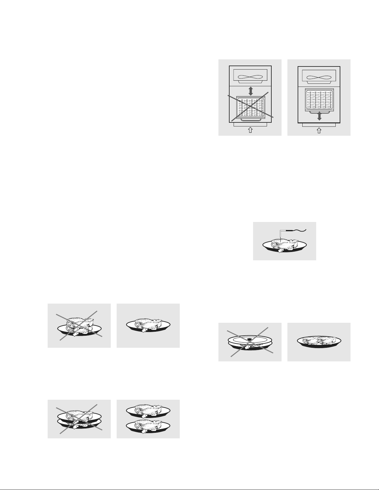
c) Position trays inside the tray compartment as
far as they will go, as close as possible to the
evaporator.
d) Position the core probe at the centre of the
largest product or food item; make sure that
the tip of the probe does not protrude or touch
the tray. If you are using the probe for a liquid
ensure that the probe is placed in the warmest
location in the warmest pan. The probe
must be cleaned and sanitized before each
new cycle (operation) to prevent inadvertent
contamination.
e) Avoid covering the trays and/or containers with
insulating covers or lm. The more the product
is insulated, the more time is required for
chilling or freezing. Trays should be packaged
when the product has been chilled, before
being placed in storage.
b) Ensure that there is sucient clearance
between trays to enable free air circulation. If
the appliance is not completely full, distribute
the trays and foods evenly throughout the
available space.
11
Page 12
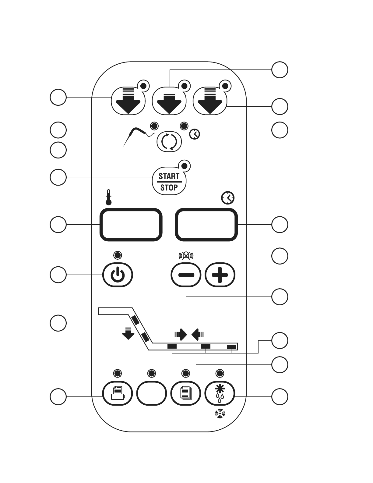
4. DESCRIPTION OF THE VERTICAL CONTROL PANEL
3
HARD
2
+38 °
+38 °
0°
4
5a
5
6
15
1
5b
°C
14
7
8
12
12
10
13
9
11
HACCP PROGRAM
Page 13

4.1
PUSH-BUTTONS
:
1.
2.
3.
4.
5.
5A.
5B.
6.
+38 °
HARD
+38 °
0°
ON /OFF (STAND BY)
SOFT BLAST CHILLING CYCLE (+38°F / +3°C)
HARD BLAST CHILLING CYCLE (+38°F / +3°C)
BLAST FREEZING CYCLE (0°F / -18°C)
END CYCLE BY TIME / PROBE (TEMPERATURE)
PROBE CHILLING INDICATOR LED
TIMED CHILLING INDICATOR LED
CYCLE START / STOP
7.
8.
9.
10.
11.
12.
13.
14.
PROGRAM
HACCP
INCREASE VALUE
DECREASE VALUE
RECIPE PROGRAMS (CHILLING CYCLES)
HACCP
DEFROSTING / FORCED VENTILATION
CHILLING / FREEZING CYCLE INDICATOR LED
STORAGE INDICATOR LED
TIME DISPLAY
15.
°C
TEMPERATURE DISPLAY
13
Page 14

PUSH-BUTTONS
:
ON /OFF (STAND BY)
SOFT BLAST CHILLING CYCLE (+38°F / +3°C)
HARD BLAST CHILLING CYCLE (+38°F / +3°C)
BLAST FREEZING CYCLE (0°F / -18°C)
END CYCLE BY TIME / PROBE (TEMPERATURE)
PROBE CHILLING INDICATOR LED
TIMED CHILLING INDICATOR LED
CYCLE START / STOP
INCREASE VALUE
DECREASE VALUE
RECIPE PROGRAMS (CHILLING CYCLES)
HACCP AND PRINTER (OPTIONAL)
DEFROSTING / FORCED VENTILATION
CHILLING / FREEZING CYCLE INDICATOR LED
STORAGE INDICATOR LED
TIME DISPLAY
HACCP
PROGRAM
0°
+38°
HARD
+38°
PUSH-BUTTONS
:
ON /OFF (STAND BY)
SOFT BLAST CHILLING CYCLE (+38°F / +3°C)
HARD BLAST CHILLING CYCLE (+38°F / +3°C)
BLAST FREEZING CYCLE (0°F / -18°C)
END CYCLE BY TIME / PROBE (TEMPERATURE)
PROBE CHILLING INDICATOR LED
TIMED CHILLING INDICATOR LED
CYCLE START / STOP
INCREASE VALUE
DECREASE VALUE
RECIPE PROGRAMS (CHILLING CYCLES)
HACCP AND PRINTER (OPTIONAL)
DEFROSTING / FORCED VENTILATION
CHILLING / FREEZING CYCLE INDICATOR LED
STORAGE INDICATOR LED
TIME DISPLAY
TEMPERATURE DISPLAY
HACCP
PROGRAM
0°
+38°
HARD
+38°
PUSH-BUTTONS
:
ON /OFF (STAND BY)
SOFT BLAST CHILLING CYCLE (+38°F / +3°C)
HARD BLAST CHILLING CYCLE (+38°F / +3°C)
BLAST FREEZING CYCLE (0°F / -18°C)
END CYCLE BY TIME / PROBE (TEMPERATURE)
PROBE CHILLING INDICATOR LED
0°
+38°
HARD
+38°
PUSH-BUTTONS
:
ON /OFF (STAND BY)
PUSH-BUTTONS
:
ON /OFF (STAND BY)
5. PROGRAMMING AND OPERATING INSTRUCTIONS
PUSH-BUTTONS
:
ON /OFF (STAND BY)
5.1 STARTING UP THE APPLIANCE (only for T14D / T40)
PRE HEATING FUNCTION OF COMPRESSOR SUP
When power is initially supplied to the cabinet, a 2-hour pre-heating phase starts and the display shows
some blinking dashes “---”. During this phase the machine cannot be started. This important information is
shown on a yellow label placed inside the door.
Initial pre-heating is necessary in order to safeguard the compressor’s life. Only if strictly necessary (and
under the customer’s responsibility) it is possible to by-pass countdown by pressing push button “HACCP”
for about 5 seconds.
This function is not activated if machine stops/starts operating due to lack of power during working cycle.
When the appliance is plugged in or connected to electrical power up, it can be:
• ON 14 and 15 illuminate and LED 5A is on, LED 1 is o
°C
• OFF-STAND-BY push-button 1 LED is on.
To switch from one status to another, press push-button 1 .
Whenever the appliance switches from STAND-BY status to ON, a self-test is carried out: all LEDs and displays
are switched on, push-buttons are checked, then the installed software version is displayed.
OPERATION
The main work cycles (chilling/freezing) performed by the appliance:
• SOFT BLAST CHILLING (+38°F / +3°C)
Pre-cooked food is rapidly chilled to a temperature of +38°F / +3°C, thus preventing proliferation of bacteria
and preventing dehydration of the cooked food due to evaporation. Food can thus be stored perfectly for 5
to 7 days without altering its original qualities. The soft cycle is recommended for delicate, thin foods such
as rice, vegetables and fried foods.
• HARD BLAST CHILLING (+38°F / +3°C)
This process is designed to cool food products with a thickness greater than 2-3 cm/1’’ and is very eective
for dense, greasy or large-sized foods. Variable air temperatures are used to accelerate penetration of cold
into the product.
• BLAST FREEZING (0°F / -18°C)
This function freezes the product completely to a temperature of 0°F / -18°C in approximately 4 hours.
The rapidity of the process prevents formation of macrocrystals essential to ensure that the product retains
its original consistency and quality when thawed for consumption.
• AUTOMATIC CONSERVATION
At the end of each cycle (chilling or freezing), the appliance will automatically switch to the required storage
temperature.
Two dierent end-cycle modes are available for each cycle:
• BY TEMPERATURE - the cycle ends when the probe reaches the required temperature.
• TIMED - cycle length is pre-set
Page 15

IMPORTANT: work cycles and modes can only be selected when the appliance is ON and a work cycle has
PUSH-BUTTONS
:
ON /OFF (STAND BY)
SOFT BLAST CHILLING CYCLE (+38°F / +3°C)
HARD BLAST CHILLING CYCLE (+38°F / +3°C)
BLAST FREEZING CYCLE (0°F / -18°C)
END CYCLE BY TIME / PROBE (TEMPERATURE)
PROBE CHILLING INDICATOR LED
TIMED CHILLING INDICATOR LED
CYCLE START / STOP
INCREASE VALUE
DECREASE VALUE
RECIPE PROGRAMS (CHILLING CYCLES)
HACCP AND PRINTER (OPTIONAL)
DEFROSTING / FORCED VENTILATION
CHILLING / FREEZING CYCLE INDICATOR LED
STORAGE INDICATOR LED
HACCP
PROGRAM
0°
+38°
HARD
+38°
PUSH-BUTTONS
:
ON /OFF (STAND BY)
SOFT BLAST CHILLING CYCLE (+38°F / +3°C)
HARD BLAST CHILLING CYCLE (+38°F / +3°C)
BLAST FREEZING CYCLE (0°F / -18°C)
END CYCLE BY TIME / PROBE (TEMPERATURE)
PROBE CHILLING INDICATOR LED
TIMED CHILLING INDICATOR LED
CYCLE START / STOP
0°
+38°
HARD
+38°
PUSH-BUTTONS
:
ON /OFF (STAND BY)
SOFT BLAST CHILLING CYCLE (+38°F / +3°C)
PUSH-BUTTONS
:
ON /OFF (STAND BY)
SOFT BLAST CHILLING CYCLE (+38°F / +3°C)
HARD BLAST CHILLING CYCLE (+38°F / +3°C)
BLAST FREEZING CYCLE (0°F / -18°C)
END CYCLE BY TIME / PROBE (TEMPERATURE)
0°
+38°
HARD
+38°
PUSH-BUTTONS
:
ON /OFF (STAND BY)
SOFT BLAST CHILLING CYCLE (+38°F / +3°C)
HARD BLAST CHILLING CYCLE (+38°F / +3°C)
BLAST FREEZING CYCLE (0°F / -18°C)
END CYCLE BY TIME / PROBE (TEMPERATURE)
PROBE CHILLING INDICATOR LED
0°
+38°
HARD
+38°
PUSH-BUTTONS
:
ON /OFF (STAND BY)
SOFT BLAST CHILLING CYCLE (+38°F / +3°C)
HARD BLAST CHILLING CYCLE (+38°F / +3°C)
BLAST FREEZING CYCLE (0°F / -18°C)
END CYCLE BY TIME / PROBE (TEMPERATURE)
PROBE CHILLING INDICATOR LED
TIMED CHILLING INDICATOR LED
CYCLE START / STOP
0°
+38°
HARD
+38°
PUSH-BUTTONS
:
ON /OFF (STAND BY)
SOFT BLAST CHILLING CYCLE (+38°F / +3°C)
HARD BLAST CHILLING CYCLE (+38°F / +3°C)
BLAST FREEZING CYCLE (0°F / -18°C)
END CYCLE BY TIME / PROBE (TEMPERATURE)
PROBE CHILLING INDICATOR LED
0°
+38°
HARD
+38°
PUSH-BUTTONS
:
ON /OFF (STAND BY)
SOFT BLAST CHILLING CYCLE (+38°F / +3°C)
HARD BLAST CHILLING CYCLE (+38°F / +3°C)
BLAST FREEZING CYCLE (0°F / -18°C)
END CYCLE BY TIME / PROBE (TEMPERATURE)
PROBE CHILLING INDICATOR LED
TIMED CHILLING INDICATOR LED
CYCLE START / STOP
INCREASE VALUE
DECREASE VALUE
RECIPE PROGRAMS (CHILLING CYCLES)
HACCP AND PRINTER (OPTIONAL)
DEFROSTING / FORCED VENTILATION
CHILLING / FREEZING CYCLE INDICATOR LED
HACCP
PROGRAM
0°
+38°
HARD
+38°
PUSH-BUTTONS
:
ON /OFF (STAND BY)
SOFT BLAST CHILLING CYCLE (+38°F / +3°C)
HARD BLAST CHILLING CYCLE (+38°F / +3°C)
BLAST FREEZING CYCLE (0°F / -18°C)
END CYCLE BY TIME / PROBE (TEMPERATURE)
PROBE CHILLING INDICATOR LED
TIMED CHILLING INDICATOR LED
CYCLE START / STOP
INCREASE VALUE
DECREASE VALUE
RECIPE PROGRAMS (CHILLING CYCLES)
HACCP AND PRINTER (OPTIONAL)
DEFROSTING / FORCED VENTILATION
CHILLING / FREEZING CYCLE INDICATOR LED
STORAGE INDICATOR LED
HACCP
PROGRAM
0°
+38°
HARD
+38°
PUSH-BUTTONS
:
ON /OFF (STAND BY)
SOFT BLAST CHILLING CYCLE (+38°F / +3°C)
HARD BLAST CHILLING CYCLE (+38°F / +3°C)
BLAST FREEZING CYCLE (0°F / -18°C)
END CYCLE BY TIME / PROBE (TEMPERATURE)
PROBE CHILLING INDICATOR LED
TIMED CHILLING INDICATOR LED
CYCLE START / STOP
INCREASE VALUE
DECREASE VALUE
RECIPE PROGRAMS (CHILLING CYCLES)
HACCP AND PRINTER (OPTIONAL)
DEFROSTING / FORCED VENTILATION
CHILLING / FREEZING CYCLE INDICATOR LED
STORAGE INDICATOR LED
TIME DISPLAY
HACCP
PROGRAM
0°
+38°
HARD
+38°
PUSH-BUTTONS
:
ON /OFF (STAND BY)
SOFT BLAST CHILLING CYCLE (+38°F / +3°C)
HARD BLAST CHILLING CYCLE (+38°F / +3°C)
BLAST FREEZING CYCLE (0°F / -18°C)
END CYCLE BY TIME / PROBE (TEMPERATURE)
PROBE CHILLING INDICATOR LED
TIMED CHILLING INDICATOR LED
CYCLE START / STOP
INCREASE VALUE
DECREASE VALUE
RECIPE PROGRAMS (CHILLING CYCLES)
HACCP AND PRINTER (OPTIONAL)
DEFROSTING / FORCED VENTILATION
CHILLING / FREEZING CYCLE INDICATOR LED
STORAGE INDICATOR LED
HACCP
PROGRAM
0°
+38°
HARD
+38°
PUSH-BUTTONS
:
ON /OFF (STAND BY)
SOFT BLAST CHILLING CYCLE (+38°F / +3°C)
HARD BLAST CHILLING CYCLE (+38°F / +3°C)
BLAST FREEZING CYCLE (0°F / -18°C)
END CYCLE BY TIME / PROBE (TEMPERATURE)
PROBE CHILLING INDICATOR LED
TIMED CHILLING INDICATOR LED
CYCLE START / STOP
INCREASE VALUE
DECREASE VALUE
RECIPE PROGRAMS (CHILLING CYCLES)
HACCP AND PRINTER (OPTIONAL)
DEFROSTING / FORCED VENTILATION
CHILLING / FREEZING CYCLE INDICATOR LED
STORAGE INDICATOR LED
HACCP
PROGRAM
0°
+38°
HARD
+38°
PUSH-BUTTONS
:
ON /OFF (STAND BY)
SOFT BLAST CHILLING CYCLE (+38°F / +3°C)
HARD BLAST CHILLING CYCLE (+38°F / +3°C)
BLAST FREEZING CYCLE (0°F / -18°C)
END CYCLE BY TIME / PROBE (TEMPERATURE)
PROBE CHILLING INDICATOR LED
TIMED CHILLING INDICATOR LED
CYCLE START / STOP
INCREASE VALUE
DECREASE VALUE
RECIPE PROGRAMS (CHILLING CYCLES)
HACCP AND PRINTER (OPTIONAL)
DEFROSTING / FORCED VENTILATION
CHILLING / FREEZING CYCLE INDICATOR LED
STORAGE INDICATOR LED
TIME DISPLAY
HACCP
PROGRAM
0°
+38°
HARD
+38°
PUSH-BUTTONS
:
ON /OFF (STAND BY)
SOFT BLAST CHILLING CYCLE (+38°F / +3°C)
HARD BLAST CHILLING CYCLE (+38°F / +3°C)
BLAST FREEZING CYCLE (0°F / -18°C)
END CYCLE BY TIME / PROBE (TEMPERATURE)
PROBE CHILLING INDICATOR LED
TIMED CHILLING INDICATOR LED
CYCLE START / STOP
INCREASE VALUE
DECREASE VALUE
RECIPE PROGRAMS (CHILLING CYCLES)
HACCP AND PRINTER (OPTIONAL)
DEFROSTING / FORCED VENTILATION
CHILLING / FREEZING CYCLE INDICATOR LED
STORAGE INDICATOR LED
TIME DISPLAY
TEMPERATURE DISPLAY
HACCP
PROGRAM
0°
+38°
HARD
+38°
PUSH-BUTTONS
:
ON /OFF (STAND BY)
SOFT BLAST CHILLING CYCLE (+38°F / +3°C)
HARD BLAST CHILLING CYCLE (+38°F / +3°C)
BLAST FREEZING CYCLE (0°F / -18°C)
END CYCLE BY TIME / PROBE (TEMPERATURE)
PROBE CHILLING INDICATOR LED
TIMED CHILLING INDICATOR LED
CYCLE START / STOP
INCREASE VALUE
DECREASE VALUE
RECIPE PROGRAMS (CHILLING CYCLES)
HACCP AND PRINTER (OPTIONAL)
DEFROSTING / FORCED VENTILATION
CHILLING / FREEZING CYCLE INDICATOR LED
STORAGE INDICATOR LED
HACCP
PROGRAM
0°
+38°
HARD
+38°
PUSH-BUTTONS
:
ON /OFF (STAND BY)
SOFT BLAST CHILLING CYCLE (+38°F / +3°C)
HARD BLAST CHILLING CYCLE (+38°F / +3°C)
BLAST FREEZING CYCLE (0°F / -18°C)
END CYCLE BY TIME / PROBE (TEMPERATURE)
PROBE CHILLING INDICATOR LED
TIMED CHILLING INDICATOR LED
CYCLE START / STOP
INCREASE VALUE
DECREASE VALUE
0°
+38°
HARD
+38°
not been started, LED on push-button 6 o
IMPORTANT: The appliance will automatically defrost if coil temperature falls below 45˚F. It will not go into
defrost during a chill or freeze cycle. When it is in defrost a new cycle can not be initiated until defrost is
complete.
5.2 SOFT BLAST CHILLING BY TEMPERATURE (pre-cooked, hot foods)
• To select this cycle, press push-button 2 (relative LED lights up), then press push-button 5
+38°
to select the temperature mode (LED 5A on)
• Insert the core probe into the core of the product to be chilled.
• Start up the cycle by pressing push-button 6 . LED 5A and those related to the push-buttons
pressed illuminate throughout the cycle, while LEDs 12 ash.
• Display 14 indicates the maximum blast chilling time (starting temperature to end of the blast
chilling temperature (factory setting 90 minutes).
• The temperature measured by the core probe is shown by display 15 .
°C
• The instrument timer starts the countdown of the maximum blast chilling time as soon as the temperature
measured by the core probe falls below the temperature of +149°F / +65°C (the dot at
the bottom right of display 14 ashes).
• During the blast chilling cycle, the air temperature is around +32°F / 0°C and may get as low as 23˚F/-5˚C.
This function is designed to guarantee uniform cooling of the product, preventing frost formation on the
surfaces. During the blast chilling cycle, the compressor may therefore stop and restart, depending on the
reading of the compartment temperature probe.
• The blast chilling phase ends only when the core probe (inserted in the product core) indicates
that the set blast chilling temperature (+38°F / +3°C) has been reached as signalled by an intermittent
beep for a minute. During the beep, LEDs 12 and 13 ash.
Display 15 indicates the temperature inside the compartment, while display 14 shows blast
chilling time reset to zero.
• If at the end of the maximum blast chilling interval the core probe continues to display a temperature
higher than the value for the end of blast chilling, the displays will indicate an alarm for excessively long
chilling
The blast chilling cycle continues until the end chilling temperature has been reached; display 14
counts back the minutes remaining until the end of the cycle.
Press push-button 8 to mute the alarm; press push-button again to clear the alarm display.
ALL 14
°C
alternating with the temperature and time; at the same time, the alarm will beep.
15
Page 16

• At the end of the chilling cycle, the appliance automatically switches to the set storage temperature for an
PUSH-BUTTONS
:
ON /OFF (STAND BY)
SOFT BLAST CHILLING CYCLE (+38°F / +3°C)
HARD BLAST CHILLING CYCLE (+38°F / +3°C)
BLAST FREEZING CYCLE (0°F / -18°C)
END CYCLE BY TIME / PROBE (TEMPERATURE)
PROBE CHILLING INDICATOR LED
TIMED CHILLING INDICATOR LED
CYCLE START / STOP
0°
+38°
HARD
+38°
PUSH-BUTTONS
:
ON /OFF (STAND BY)
SOFT BLAST CHILLING CYCLE (+38°F / +3°C)
HARD BLAST CHILLING CYCLE (+38°F / +3°C)
BLAST FREEZING CYCLE (0°F / -18°C)
END CYCLE BY TIME / PROBE (TEMPERATURE)
PROBE CHILLING INDICATOR LED
TIMED CHILLING INDICATOR LED
CYCLE START / STOP
INCREASE VALUE
DECREASE VALUE
RECIPE PROGRAMS (CHILLING CYCLES)
HACCP AND PRINTER (OPTIONAL)
HACCP
PROGRAM
0°
+38°
HARD
+38°
PUSH-BUTTONS
:
ON /OFF (STAND BY)
SOFT BLAST CHILLING CYCLE (+38°F / +3°C)
HARD BLAST CHILLING CYCLE (+38°F / +3°C)
BLAST FREEZING CYCLE (0°F / -18°C)
END CYCLE BY TIME / PROBE (TEMPERATURE)
PROBE CHILLING INDICATOR LED
TIMED CHILLING INDICATOR LED
CYCLE START / STOP
INCREASE VALUE
DECREASE VALUE
RECIPE PROGRAMS (CHILLING CYCLES)
HACCP AND PRINTER (OPTIONAL)
HACCP
PROGRAM
0°
+38°
HARD
+38°
PUSH-BUTTONS
:
ON /OFF (STAND BY)
SOFT BLAST CHILLING CYCLE (+38°F / +3°C)
HARD BLAST CHILLING CYCLE (+38°F / +3°C)
BLAST FREEZING CYCLE (0°F / -18°C)
END CYCLE BY TIME / PROBE (TEMPERATURE)
PROBE CHILLING INDICATOR LED
TIMED CHILLING INDICATOR LED
CYCLE START / STOP
INCREASE VALUE
DECREASE VALUE
RECIPE PROGRAMS (CHILLING CYCLES)
HACCP AND PRINTER (OPTIONAL)
DEFROSTING / FORCED VENTILATION
CHILLING / FREEZING CYCLE INDICATOR LED
STORAGE INDICATOR LED
HACCP
PROGRAM
0°
+38°
HARD
+38°
PUSH-BUTTONS
:
ON /OFF (STAND BY)
SOFT BLAST CHILLING CYCLE (+38°F / +3°C)
HARD BLAST CHILLING CYCLE (+38°F / +3°C)
BLAST FREEZING CYCLE (0°F / -18°C)
END CYCLE BY TIME / PROBE (TEMPERATURE)
PROBE CHILLING INDICATOR LED
TIMED CHILLING INDICATOR LED
CYCLE START / STOP
INCREASE VALUE
DECREASE VALUE
RECIPE PROGRAMS (CHILLING CYCLES)
HACCP AND PRINTER (OPTIONAL)
DEFROSTING / FORCED VENTILATION
CHILLING / FREEZING CYCLE INDICATOR LED
STORAGE INDICATOR LED
TIME DISPLAY
TEMPERATURE DISPLAY
HACCP
PROGRAM
0°
+38°
HARD
+38°
PUSH-BUTTONS
:
ON /OFF (STAND BY)
SOFT BLAST CHILLING CYCLE (+38°F / +3°C)
PUSH-BUTTONS
:
ON /OFF (STAND BY)
SOFT BLAST CHILLING CYCLE (+38°F / +3°C)
HARD BLAST CHILLING CYCLE (+38°F / +3°C)
BLAST FREEZING CYCLE (0°F / -18°C)
END CYCLE BY TIME / PROBE (TEMPERATURE)
0°
+38°
HARD
+38°
PUSH-BUTTONS
:
ON /OFF (STAND BY)
SOFT BLAST CHILLING CYCLE (+38°F / +3°C)
HARD BLAST CHILLING CYCLE (+38°F / +3°C)
BLAST FREEZING CYCLE (0°F / -18°C)
END CYCLE BY TIME / PROBE (TEMPERATURE)
PROBE CHILLING INDICATOR LED
TIMED CHILLING INDICATOR LED
0°
+38°
HARD
+38°
PUSH-BUTTONS
:
ON /OFF (STAND BY)
SOFT BLAST CHILLING CYCLE (+38°F / +3°C)
HARD BLAST CHILLING CYCLE (+38°F / +3°C)
BLAST FREEZING CYCLE (0°F / -18°C)
END CYCLE BY TIME / PROBE (TEMPERATURE)
PROBE CHILLING INDICATOR LED
TIMED CHILLING INDICATOR LED
CYCLE START / STOP
INCREASE VALUE
DECREASE VALUE
RECIPE PROGRAMS (CHILLING CYCLES)
HACCP AND PRINTER (OPTIONAL)
DEFROSTING / FORCED VENTILATION
CHILLING / FREEZING CYCLE INDICATOR LED
STORAGE INDICATOR LED
HACCP
PROGRAM
0°
+38°
HARD
+38°
PUSH-BUTTONS
:
ON /OFF (STAND BY)
SOFT BLAST CHILLING CYCLE (+38°F / +3°C)
HARD BLAST CHILLING CYCLE (+38°F / +3°C)
BLAST FREEZING CYCLE (0°F / -18°C)
END CYCLE BY TIME / PROBE (TEMPERATURE)
PROBE CHILLING INDICATOR LED
TIMED CHILLING INDICATOR LED
CYCLE START / STOP
INCREASE VALUE
DECREASE VALUE
0°
+38°
HARD
+38°
PUSH-BUTTONS
:
ON /OFF (STAND BY)
SOFT BLAST CHILLING CYCLE (+38°F / +3°C)
HARD BLAST CHILLING CYCLE (+38°F / +3°C)
BLAST FREEZING CYCLE (0°F / -18°C)
END CYCLE BY TIME / PROBE (TEMPERATURE)
PROBE CHILLING INDICATOR LED
TIMED CHILLING INDICATOR LED
0°
+38°
HARD
+38°
:
ON /OFF (STAND BY)
SOFT BLAST CHILLING CYCLE (+38°F / +3°C)
HARD BLAST CHILLING CYCLE (+38°F / +3°C)
BLAST FREEZING CYCLE (0°F / -18°C)
END CYCLE BY TIME / PROBE (TEMPERATURE)
PROBE CHILLING INDICATOR LED
TIMED CHILLING INDICATOR LED
CYCLE START / STOP
INCREASE VALUE
DECREASE VALUE
RECIPE PROGRAMS (CHILLING CYCLES)
HACCP AND PRINTER (OPTIONAL)
DEFROSTING / FORCED VENTILATION
CHILLING / FREEZING CYCLE INDICATOR LED
HACCP
PROGRAM
0°
+38°
HARD
+38°
PUSH-BUTTONS
:
ON /OFF (STAND BY)
SOFT BLAST CHILLING CYCLE (+38°F / +3°C)
HARD BLAST CHILLING CYCLE (+38°F / +3°C)
BLAST FREEZING CYCLE (0°F / -18°C)
END CYCLE BY TIME / PROBE (TEMPERATURE)
PROBE CHILLING INDICATOR LED
TIMED CHILLING INDICATOR LED
CYCLE START / STOP
INCREASE VALUE
DECREASE VALUE
RECIPE PROGRAMS (CHILLING CYCLES)
HACCP AND PRINTER (OPTIONAL)
DEFROSTING / FORCED VENTILATION
CHILLING / FREEZING CYCLE INDICATOR LED
STORAGE INDICATOR LED
TIME DISPLAY
TEMPERATURE DISPLAY
HACCP
PROGRAM
0°
+38°
HARD
+38°
PUSH-BUTTONS
:
ON /OFF (STAND BY)
SOFT BLAST CHILLING CYCLE (+38°F / +3°C)
HARD BLAST CHILLING CYCLE (+38°F / +3°C)
BLAST FREEZING CYCLE (0°F / -18°C)
END CYCLE BY TIME / PROBE (TEMPERATURE)
PROBE CHILLING INDICATOR LED
TIMED CHILLING INDICATOR LED
CYCLE START / STOP
0°
+38°
HARD
+38°
PUSH-BUTTONS
:
ON /OFF (STAND BY)
SOFT BLAST CHILLING CYCLE (+38°F / +3°C)
HARD BLAST CHILLING CYCLE (+38°F / +3°C)
BLAST FREEZING CYCLE (0°F / -18°C)
END CYCLE BY TIME / PROBE (TEMPERATURE)
PROBE CHILLING INDICATOR LED
TIMED CHILLING INDICATOR LED
CYCLE START / STOP
0°
+38°
HARD
+38°
indenite interval (like a standard storage appliance).
LEDs 12 switch o while LEDs 13 light up.
• The compartment temperature is constantly shown on display 15; during this cycle, defrost cycles
°C
are performed at regular intervals with duration set as required (parameter programming reserved for
installation technician). The factory setting for positive storage temperature is +36°F / +2°C.
• Press push-button 6
to set the appliance to STOP status (relative LED switches o), ready for a new
cycle.
To modify the nal blast chilling temperature, consult the user programming instructions.
IMPORTANT: During chilling or shock freezing by core sensor it’s possible to read:
- The room temperature by pressing push button 10
- The evaporator temperature by pressing push button 10
.
HACCP
.
5.3 SOFT TIMED BLAST CHILLING
• Press push-button 2 (relative LED lights up), then press push-button 5 to select the timer mode
+38°
(LED 5B on). Display 14 shows the maximum chilling time (set by default to 90 minutes).
To modify this time, press push-buttons 7 and 8 (time in minutes).
• Press push-button 6 to start the appliance. LED 5B and push-button LEDs remain on and LEDs 12
ash throughout the cycle.
Internal cabinet temperature is shown on display 15 .
• When the maximum chilling time has counted back to 0, the chilling cycle is completed and the appliance
automatically switches to the set positive storage temperature for an indenite interval.
• LEDs illuminate and the alarm will beep when the cycle is nished (as in the chilling cycle by temperature).
The same applies for the positive storage function.
Press push-button 6 to set the appliance to STOP status (relative LED switches o), ready for a new cycle.
IMPORTANT: Use the storage function sparingly. After chilling, food products should be placed in
storage cabinets.
HARD BLAST CHILLING
When the HARD function is used, chilling takes place in two stages:
• an initial “Hard” stage when the air temperature is brought down to below 32°F / 0°C in order to accelerate
chilling;
• a second “Soft” stage, involving air temperatures around 32°F.
IMPORTANT: During chilling or shock freezing by time it’s possible to read the evaporator
temperature by pressing push button 10
16
.
°C
Page 17

5.4 HARD BLAST CHILLING BY TEMPERATURE
PUSH-BUTTONS
:
ON /OFF (STAND BY)
SOFT BLAST CHILLING CYCLE (+38°F / +3°C)
HARD BLAST CHILLING CYCLE (+38°F / +3°C)
BLAST FREEZING CYCLE (0°F / -18°C)
END CYCLE BY TIME / PROBE (TEMPERATURE)
PROBE CHILLING INDICATOR LED
TIMED CHILLING INDICATOR LED
CYCLE START / STOP
INCREASE VALUE
DECREASE VALUE
RECIPE PROGRAMS (CHILLING CYCLES)
HACCP AND PRINTER (OPTIONAL)
DEFROSTING / FORCED VENTILATION
CHILLING / FREEZING CYCLE INDICATOR LED
STORAGE INDICATOR LED
HACCP
PROGRAM
0°
+38°
HARD
+38°
PUSH-BUTTONS
:
ON /OFF (STAND BY)
SOFT BLAST CHILLING CYCLE (+38°F / +3°C)
HARD BLAST CHILLING CYCLE (+38°F / +3°C)
BLAST FREEZING CYCLE (0°F / -18°C)
END CYCLE BY TIME / PROBE (TEMPERATURE)
PROBE CHILLING INDICATOR LED
TIMED CHILLING INDICATOR LED
CYCLE START / STOP
INCREASE VALUE
DECREASE VALUE
RECIPE PROGRAMS (CHILLING CYCLES)
HACCP AND PRINTER (OPTIONAL)
HACCP
PROGRAM
0°
+38°
HARD
+38°
PUSH-BUTTONS
:
ON /OFF (STAND BY)
SOFT BLAST CHILLING CYCLE (+38°F / +3°C)
HARD BLAST CHILLING CYCLE (+38°F / +3°C)
+38°
PUSH-BUTTONS
:
ON /OFF (STAND BY)
SOFT BLAST CHILLING CYCLE (+38°F / +3°C)
HARD BLAST CHILLING CYCLE (+38°F / +3°C)
BLAST FREEZING CYCLE (0°F / -18°C)
END CYCLE BY TIME / PROBE (TEMPERATURE)
0°
+38°
HARD
+38°
PUSH-BUTTONS
:
ON /OFF (STAND BY)
SOFT BLAST CHILLING CYCLE (+38°F / +3°C)
HARD BLAST CHILLING CYCLE (+38°F / +3°C)
BLAST FREEZING CYCLE (0°F / -18°C)
END CYCLE BY TIME / PROBE (TEMPERATURE)
PROBE CHILLING INDICATOR LED
0°
+38°
HARD
+38°
PUSH-BUTTONS
:
ON /OFF (STAND BY)
SOFT BLAST CHILLING CYCLE (+38°F / +3°C)
HARD BLAST CHILLING CYCLE (+38°F / +3°C)
BLAST FREEZING CYCLE (0°F / -18°C)
END CYCLE BY TIME / PROBE (TEMPERATURE)
PROBE CHILLING INDICATOR LED
TIMED CHILLING INDICATOR LED
CYCLE START / STOP
0°
+38°
HARD
+38°
PUSH-BUTTONS
:
ON /OFF (STAND BY)
SOFT BLAST CHILLING CYCLE (+38°F / +3°C)
HARD BLAST CHILLING CYCLE (+38°F / +3°C)
BLAST FREEZING CYCLE (0°F / -18°C)
END CYCLE BY TIME / PROBE (TEMPERATURE)
PROBE CHILLING INDICATOR LED
0°
+38°
HARD
+38°
PUSH-BUTTONS
:
ON /OFF (STAND BY)
SOFT BLAST CHILLING CYCLE (+38°F / +3°C)
HARD BLAST CHILLING CYCLE (+38°F / +3°C)
BLAST FREEZING CYCLE (0°F / -18°C)
END CYCLE BY TIME / PROBE (TEMPERATURE)
PROBE CHILLING INDICATOR LED
TIMED CHILLING INDICATOR LED
CYCLE START / STOP
INCREASE VALUE
DECREASE VALUE
RECIPE PROGRAMS (CHILLING CYCLES)
HACCP AND PRINTER (OPTIONAL)
DEFROSTING / FORCED VENTILATION
CHILLING / FREEZING CYCLE INDICATOR LED
HACCP
PROGRAM
0°
+38°
HARD
+38°
PUSH-BUTTONS
:
ON /OFF (STAND BY)
SOFT BLAST CHILLING CYCLE (+38°F / +3°C)
HARD BLAST CHILLING CYCLE (+38°F / +3°C)
BLAST FREEZING CYCLE (0°F / -18°C)
END CYCLE BY TIME / PROBE (TEMPERATURE)
PROBE CHILLING INDICATOR LED
TIMED CHILLING INDICATOR LED
CYCLE START / STOP
INCREASE VALUE
DECREASE VALUE
RECIPE PROGRAMS (CHILLING CYCLES)
HACCP AND PRINTER (OPTIONAL)
DEFROSTING / FORCED VENTILATION
CHILLING / FREEZING CYCLE INDICATOR LED
STORAGE INDICATOR LED
HACCP
PROGRAM
0°
+38°
HARD
+38°
PUSH-BUTTONS
:
ON /OFF (STAND BY)
SOFT BLAST CHILLING CYCLE (+38°F / +3°C)
HARD BLAST CHILLING CYCLE (+38°F / +3°C)
BLAST FREEZING CYCLE (0°F / -18°C)
END CYCLE BY TIME / PROBE (TEMPERATURE)
PROBE CHILLING INDICATOR LED
TIMED CHILLING INDICATOR LED
CYCLE START / STOP
INCREASE VALUE
DECREASE VALUE
RECIPE PROGRAMS (CHILLING CYCLES)
HACCP AND PRINTER (OPTIONAL)
DEFROSTING / FORCED VENTILATION
CHILLING / FREEZING CYCLE INDICATOR LED
STORAGE INDICATOR LED
TIME DISPLAY
TEMPERATURE DISPLAY
HACCP
PROGRAM
0°
+38°
HARD
+38°
PUSH-BUTTONS
:
ON /OFF (STAND BY)
SOFT BLAST CHILLING CYCLE (+38°F / +3°C)
HARD BLAST CHILLING CYCLE (+38°F / +3°C)
BLAST FREEZING CYCLE (0°F / -18°C)
END CYCLE BY TIME / PROBE (TEMPERATURE)
PROBE CHILLING INDICATOR LED
TIMED CHILLING INDICATOR LED
CYCLE START / STOP
INCREASE VALUE
DECREASE VALUE
RECIPE PROGRAMS (CHILLING CYCLES)
HACCP AND PRINTER (OPTIONAL)
DEFROSTING / FORCED VENTILATION
CHILLING / FREEZING CYCLE INDICATOR LED
STORAGE INDICATOR LED
TIME DISPLAY
HACCP
PROGRAM
0°
+38°
HARD
+38°
PUSH-BUTTONS
:
ON /OFF (STAND BY)
SOFT BLAST CHILLING CYCLE (+38°F / +3°C)
HARD BLAST CHILLING CYCLE (+38°F / +3°C)
BLAST FREEZING CYCLE (0°F / -18°C)
END CYCLE BY TIME / PROBE (TEMPERATURE)
PROBE CHILLING INDICATOR LED
TIMED CHILLING INDICATOR LED
CYCLE START / STOP
INCREASE VALUE
DECREASE VALUE
RECIPE PROGRAMS (CHILLING CYCLES)
HACCP AND PRINTER (OPTIONAL)
DEFROSTING / FORCED VENTILATION
CHILLING / FREEZING CYCLE INDICATOR LED
STORAGE INDICATOR LED
HACCP
PROGRAM
0°
+38°
HARD
+38°
PUSH-BUTTONS
:
ON /OFF (STAND BY)
SOFT BLAST CHILLING CYCLE (+38°F / +3°C)
HARD BLAST CHILLING CYCLE (+38°F / +3°C)
BLAST FREEZING CYCLE (0°F / -18°C)
END CYCLE BY TIME / PROBE (TEMPERATURE)
PROBE CHILLING INDICATOR LED
TIMED CHILLING INDICATOR LED
CYCLE START / STOP
0°
+38°
HARD
+38°
PUSH-BUTTONS
:
ON /OFF (STAND BY)
SOFT BLAST CHILLING CYCLE (+38°F / +3°C)
HARD BLAST CHILLING CYCLE (+38°F / +3°C)
+38°
PUSH-BUTTONS
:
ON /OFF (STAND BY)
SOFT BLAST CHILLING CYCLE (+38°F / +3°C)
HARD BLAST CHILLING CYCLE (+38°F / +3°C)
BLAST FREEZING CYCLE (0°F / -18°C)
END CYCLE BY TIME / PROBE (TEMPERATURE)
0°
+38°
HARD
+38°
PUSH-BUTTONS
:
ON /OFF (STAND BY)
SOFT BLAST CHILLING CYCLE (+38°F / +3°C)
HARD BLAST CHILLING CYCLE (+38°F / +3°C)
BLAST FREEZING CYCLE (0°F / -18°C)
END CYCLE BY TIME / PROBE (TEMPERATURE)
PROBE CHILLING INDICATOR LED
TIMED CHILLING INDICATOR LED
0°
+38°
HARD
+38°
PUSH-BUTTONS
:
ON /OFF (STAND BY)
SOFT BLAST CHILLING CYCLE (+38°F / +3°C)
HARD BLAST CHILLING CYCLE (+38°F / +3°C)
BLAST FREEZING CYCLE (0°F / -18°C)
END CYCLE BY TIME / PROBE (TEMPERATURE)
PROBE CHILLING INDICATOR LED
TIMED CHILLING INDICATOR LED
CYCLE START / STOP
INCREASE VALUE
DECREASE VALUE
RECIPE PROGRAMS (CHILLING CYCLES)
HACCP AND PRINTER (OPTIONAL)
DEFROSTING / FORCED VENTILATION
CHILLING / FREEZING CYCLE INDICATOR LED
STORAGE INDICATOR LED
TIME DISPLAY
HACCP
PROGRAM
0°
+38°
HARD
+38°
PUSH-BUTTONS
:
ON /OFF (STAND BY)
SOFT BLAST CHILLING CYCLE (+38°F / +3°C)
HARD BLAST CHILLING CYCLE (+38°F / +3°C)
BLAST FREEZING CYCLE (0°F / -18°C)
END CYCLE BY TIME / PROBE (TEMPERATURE)
PROBE CHILLING INDICATOR LED
TIMED CHILLING INDICATOR LED
CYCLE START / STOP
INCREASE VALUE
DECREASE VALUE
0°
+38°
HARD
+38°
PUSH-BUTTONS
:
ON /OFF (STAND BY)
SOFT BLAST CHILLING CYCLE (+38°F / +3°C)
HARD BLAST CHILLING CYCLE (+38°F / +3°C)
+38°
PUSH-BUTTONS
:
ON /OFF (STAND BY)
SOFT BLAST CHILLING CYCLE (+38°F / +3°C)
HARD BLAST CHILLING CYCLE (+38°F / +3°C)
BLAST FREEZING CYCLE (0°F / -18°C)
END CYCLE BY TIME / PROBE (TEMPERATURE)
PROBE CHILLING INDICATOR LED
TIMED CHILLING INDICATOR LED
CYCLE START / STOP
INCREASE VALUE
DECREASE VALUE
RECIPE PROGRAMS (CHILLING CYCLES)
HACCP AND PRINTER (OPTIONAL)
DEFROSTING / FORCED VENTILATION
CHILLING / FREEZING CYCLE INDICATOR LED
STORAGE INDICATOR LED
TIME DISPLAY
HACCP
PROGRAM
0°
+38°
HARD
+38°
PUSH-BUTTONS
:
ON /OFF (STAND BY)
SOFT BLAST CHILLING CYCLE (+38°F / +3°C)
HARD BLAST CHILLING CYCLE (+38°F / +3°C)
+38°
PUSH-BUTTONS
:
ON /OFF (STAND BY)
SOFT BLAST CHILLING CYCLE (+38°F / +3°C)
HARD BLAST CHILLING CYCLE (+38°F / +3°C)
+38°
HARD
• Press push-button 3 (relative LED lights up), then press push-button 5 to select the temperature
+38°
mode (LED 5A on). Insert the core probe into the core of the product to be chilled.
• Start up the cycle by pressing push-button 6 . LED 5A and those relative to the push-buttons pressed
illuminate throughout the cycle, while LED 12 ashes.
• Display 14 indicates the maximum blast chilling time (starting temperature to end of the blast
chilling temperature - factory setting - 90 minutes).
• The temperature measured by the core probe is shown by display 15 .
°C
• The instrument timer starts the countdown of the maximum blast chilling time as soon as the temperature
measured by the core probe falls below the temperature of +149°F / +65°C (the dot at the bottom right of
display 14 ashes).
• Once the cycle has been started, the appliance operates initially with an air temperature below +32°F / 0°C
HARD
(LED on push-button 3 ashes), then with temperatures around +32°F / 0°C (LED on push-button 3 on).
+38°
HARD
+38°
The rst stage of the cycle is completed when the core probe detects a temperature of +68°F / +20°C in the
product core.
• The blast chilling phase ends only when the core probe (inserted in the product core) indicates that the set
blast chilling temperature (+38°F / +3°C) has been reached as signalled by an intermittent beep for a minute.
During the beep, LEDs 12 and 13 ash.
Display 15 indicates the temperature inside the cabinet, while display 14 shows blast chilling
°C
time reset to zero.
• The alarm
Soft blast chilling.
ALL 14
and conservation functions cut in with relative indicators in the same way as for timed
• Press push-button 6 to set the appliance to STOP status (relative LED switches o), ready for a new cycle.
IMPORTANT
HARD blast chilling aords a considerable reduction in working time, and is particularly suited to foods with
a high fat content, for large pieces or for packaged products.
SOFT chilling is recommended for delicate and nely chopped products, such as vegetables, mousses, etc..
IMPORTANT: During chilling or shock freezing by core sensor it’s possible to read:
- The evaporator temperature by pressing push button 10
5.5 HARD TIMED BLAST CHILLING
• To select this cycle, press push-button 3 (relative LED lights up), then press push-button 5 to
select the “timed” mode (LED 5B on). Display 14 shows the maximum chilling time (set by default
to 90 minutes).
To modify this time, press push-buttons 7 and 8 (time in minutes).
• To set the time of the rst negative temperature stage, press push-button 3 for ve seconds, then wait
for display 14 to show the ashing value.
HARD
+38°
.
HARD
+38°
Page 18

The time setting (in minutes) can be modied by means of push-buttons 7
PUSH-BUTTONS
:
ON /OFF (STAND BY)
SOFT BLAST CHILLING CYCLE (+38°F / +3°C)
HARD BLAST CHILLING CYCLE (+38°F / +3°C)
BLAST FREEZING CYCLE (0°F / -18°C)
END CYCLE BY TIME / PROBE (TEMPERATURE)
PROBE CHILLING INDICATOR LED
TIMED CHILLING INDICATOR LED
CYCLE START / STOP
INCREASE VALUE
0°
+38°
HARD
+38°
PUSH-BUTTONS
:
ON /OFF (STAND BY)
SOFT BLAST CHILLING CYCLE (+38°F / +3°C)
HARD BLAST CHILLING CYCLE (+38°F / +3°C)
BLAST FREEZING CYCLE (0°F / -18°C)
END CYCLE BY TIME / PROBE (TEMPERATURE)
PROBE CHILLING INDICATOR LED
TIMED CHILLING INDICATOR LED
CYCLE START / STOP
INCREASE VALUE
DECREASE VALUE
0°
+38°
HARD
+38°
PUSH-BUTTONS
:
ON /OFF (STAND BY)
SOFT BLAST CHILLING CYCLE (+38°F / +3°C)
HARD BLAST CHILLING CYCLE (+38°F / +3°C)
+38°
PUSH-BUTTONS
:
ON /OFF (STAND BY)
SOFT BLAST CHILLING CYCLE (+38°F / +3°C)
HARD BLAST CHILLING CYCLE (+38°F / +3°C)
BLAST FREEZING CYCLE (0°F / -18°C)
END CYCLE BY TIME / PROBE (TEMPERATURE)
PROBE CHILLING INDICATOR LED
TIMED CHILLING INDICATOR LED
CYCLE START / STOP
0°
+38°
HARD
+38°
PUSH-BUTTONS
:
ON /OFF (STAND BY)
SOFT BLAST CHILLING CYCLE (+38°F / +3°C)
HARD BLAST CHILLING CYCLE (+38°F / +3°C)
BLAST FREEZING CYCLE (0°F / -18°C)
END CYCLE BY TIME / PROBE (TEMPERATURE)
PROBE CHILLING INDICATOR LED
TIMED CHILLING INDICATOR LED
0°
+38°
HARD
+38°
PUSH-BUTTONS
:
ON /OFF (STAND BY)
SOFT BLAST CHILLING CYCLE (+38°F / +3°C)
HARD BLAST CHILLING CYCLE (+38°F / +3°C)
BLAST FREEZING CYCLE (0°F / -18°C)
END CYCLE BY TIME / PROBE (TEMPERATURE)
PROBE CHILLING INDICATOR LED
TIMED CHILLING INDICATOR LED
CYCLE START / STOP
INCREASE VALUE
DECREASE VALUE
RECIPE PROGRAMS (CHILLING CYCLES)
HACCP AND PRINTER (OPTIONAL)
DEFROSTING / FORCED VENTILATION
CHILLING / FREEZING CYCLE INDICATOR LED
HACCP
PROGRAM
0°
+38°
HARD
+38°
PUSH-BUTTONS
:
ON /OFF (STAND BY)
SOFT BLAST CHILLING CYCLE (+38°F / +3°C)
HARD BLAST CHILLING CYCLE (+38°F / +3°C)
BLAST FREEZING CYCLE (0°F / -18°C)
END CYCLE BY TIME / PROBE (TEMPERATURE)
PROBE CHILLING INDICATOR LED
TIMED CHILLING INDICATOR LED
CYCLE START / STOP
INCREASE VALUE
DECREASE VALUE
RECIPE PROGRAMS (CHILLING CYCLES)
HACCP AND PRINTER (OPTIONAL)
DEFROSTING / FORCED VENTILATION
CHILLING / FREEZING CYCLE INDICATOR LED
STORAGE INDICATOR LED
TIME DISPLAY
TEMPERATURE DISPLAY
HACCP
PROGRAM
0°
+38°
HARD
+38°
PUSH-BUTTONS
:
ON /OFF (STAND BY)
SOFT BLAST CHILLING CYCLE (+38°F / +3°C)
HARD BLAST CHILLING CYCLE (+38°F / +3°C)
+38°
PUSH-BUTTONS
:
ON /OFF (STAND BY)
SOFT BLAST CHILLING CYCLE (+38°F / +3°C)
HARD BLAST CHILLING CYCLE (+38°F / +3°C)
+38°
PUSH-BUTTONS
:
ON /OFF (STAND BY)
SOFT BLAST CHILLING CYCLE (+38°F / +3°C)
HARD BLAST CHILLING CYCLE (+38°F / +3°C)
BLAST FREEZING CYCLE (0°F / -18°C)
END CYCLE BY TIME / PROBE (TEMPERATURE)
PROBE CHILLING INDICATOR LED
TIMED CHILLING INDICATOR LED
CYCLE START / STOP
0°
+38°
HARD
+38°
PUSH-BUTTONS
:
ON /OFF (STAND BY)
SOFT BLAST CHILLING CYCLE (+38°F / +3°C)
HARD BLAST CHILLING CYCLE (+38°F / +3°C)
BLAST FREEZING CYCLE (0°F / -18°C)
+38°
HARD
+38°
PUSH-BUTTONS
:
ON /OFF (STAND BY)
SOFT BLAST CHILLING CYCLE (+38°F / +3°C)
HARD BLAST CHILLING CYCLE (+38°F / +3°C)
BLAST FREEZING CYCLE (0°F / -18°C)
0°
+38°
HARD
+38°
PUSH-BUTTONS
:
ON /OFF (STAND BY)
SOFT BLAST CHILLING CYCLE (+38°F / +3°C)
HARD BLAST CHILLING CYCLE (+38°F / +3°C)
BLAST FREEZING CYCLE (0°F / -18°C)
END CYCLE BY TIME / PROBE (TEMPERATURE)
PROBE CHILLING INDICATOR LED
0°
+38°
HARD
+38°
PUSH-BUTTONS
:
ON /OFF (STAND BY)
SOFT BLAST CHILLING CYCLE (+38°F / +3°C)
HARD BLAST CHILLING CYCLE (+38°F / +3°C)
BLAST FREEZING CYCLE (0°F / -18°C)
END CYCLE BY TIME / PROBE (TEMPERATURE)
PROBE CHILLING INDICATOR LED
TIMED CHILLING INDICATOR LED
CYCLE START / STOP
0°
+38°
HARD
+38°
PUSH-BUTTONS
:
ON /OFF (STAND BY)
SOFT BLAST CHILLING CYCLE (+38°F / +3°C)
HARD BLAST CHILLING CYCLE (+38°F / +3°C)
BLAST FREEZING CYCLE (0°F / -18°C)
END CYCLE BY TIME / PROBE (TEMPERATURE)
PROBE CHILLING INDICATOR LED
0°
+38°
HARD
+38°
PUSH-BUTTONS
:
ON /OFF (STAND BY)
SOFT BLAST CHILLING CYCLE (+38°F / +3°C)
HARD BLAST CHILLING CYCLE (+38°F / +3°C)
BLAST FREEZING CYCLE (0°F / -18°C)
END CYCLE BY TIME / PROBE (TEMPERATURE)
PROBE CHILLING INDICATOR LED
TIMED CHILLING INDICATOR LED
CYCLE START / STOP
INCREASE VALUE
DECREASE VALUE
RECIPE PROGRAMS (CHILLING CYCLES)
HACCP AND PRINTER (OPTIONAL)
DEFROSTING / FORCED VENTILATION
CHILLING / FREEZING CYCLE INDICATOR LED
HACCP
PROGRAM
0°
+38°
HARD
+38°
PUSH-BUTTONS
:
ON /OFF (STAND BY)
SOFT BLAST CHILLING CYCLE (+38°F / +3°C)
HARD BLAST CHILLING CYCLE (+38°F / +3°C)
BLAST FREEZING CYCLE (0°F / -18°C)
END CYCLE BY TIME / PROBE (TEMPERATURE)
PROBE CHILLING INDICATOR LED
TIMED CHILLING INDICATOR LED
CYCLE START / STOP
0°
+38°
HARD
+38°
PUSH-BUTTONS
:
ON /OFF (STAND BY)
SOFT BLAST CHILLING CYCLE (+38°F / +3°C)
HARD BLAST CHILLING CYCLE (+38°F / +3°C)
BLAST FREEZING CYCLE (0°F / -18°C)
END CYCLE BY TIME / PROBE (TEMPERATURE)
PROBE CHILLING INDICATOR LED
TIMED CHILLING INDICATOR LED
CYCLE START / STOP
INCREASE VALUE
DECREASE VALUE
RECIPE PROGRAMS (CHILLING CYCLES)
HACCP AND PRINTER (OPTIONAL)
PROGRAM
0°
+38°
HARD
+38°
PUSH-BUTTONS
:
ON /OFF (STAND BY)
SOFT BLAST CHILLING CYCLE (+38°F / +3°C)
HARD BLAST CHILLING CYCLE (+38°F / +3°C)
BLAST FREEZING CYCLE (0°F / -18°C)
END CYCLE BY TIME / PROBE (TEMPERATURE)
PROBE CHILLING INDICATOR LED
TIMED CHILLING INDICATOR LED
CYCLE START / STOP
INCREASE VALUE
DECREASE VALUE
RECIPE PROGRAMS (CHILLING CYCLES)
HACCP AND PRINTER (OPTIONAL)
HACCP
PROGRAM
0°
+38°
HARD
+38°
PUSH-BUTTONS
:
ON /OFF (STAND BY)
SOFT BLAST CHILLING CYCLE (+38°F / +3°C)
HARD BLAST CHILLING CYCLE (+38°F / +3°C)
BLAST FREEZING CYCLE (0°F / -18°C)
END CYCLE BY TIME / PROBE (TEMPERATURE)
PROBE CHILLING INDICATOR LED
TIMED CHILLING INDICATOR LED
CYCLE START / STOP
INCREASE VALUE
DECREASE VALUE
RECIPE PROGRAMS (CHILLING CYCLES)
HACCP AND PRINTER (OPTIONAL)
DEFROSTING / FORCED VENTILATION
CHILLING / FREEZING CYCLE INDICATOR LED
STORAGE INDICATOR LED
HACCP
PROGRAM
0°
+38°
HARD
+38°
HARD
Press push-button 3
+38°
again to return to standard display.
and 8
.
• Start up the cycle by pressing push-button 6
LEDs 12
ash throughout the cycle.
. LED 5B
• Internal cabinet temperature is shown on display 15
and push-button LEDs remain on and
°C
.
• Once the cycle has been started, the appliance operates initially with an air temperature below +32°F /
HARD
0°C (LED on push-button 3
HARD
on). For example: HARD timed chilling cycle 90 minutes. First stage of 40 minutes with negative air
3
+38°
ashes), then with temperatures around +32°F / 0°C (LED on push-button
+38°
temperature. Second cycle stage of 50 minutes with air temperature around +32°F / 0°C.
• When the maximum chilling time has counted back to 0, the chilling cycle is completed and the appliance
automatically switches to the set positive storage temperature for an indenite interval.
• LEDs illuminate and the alarm will beep when the cycle is nished (as in the temperature chilling cycle). The
same applies for the storage function.
• Press push-button 6 to set the appliance to STOP status (relative LED switches o), ready for a new
cycle.
IMPORTANT: During chilling or shock freezing by time it’s possible to read the evaporator temperature by
pressing push button 10 .
5.6 BLAST FREEZING BY TEMPERATURE
• To select this cycle, press push-button 4 (relative LED lights up), then press push-button 5 to
select the temperature mode (LED 5A on). Insert the core probe into the core of the product to be chilled.
• Start up the cycle by pressing push-button 6 . LED 5A and those relative to the pushbuttons pressed
illuminate throughout the cycle, while LEDs 12 ash.
• The appliance proceeds to operate in the same way as that described for the positive chilling cycle.
During this cycle the compressor operates in continuous mode to enable the appliance to reach the cycle
end temperature in the shortest time possible (default temperature at product core is set at 0°F / -18°C).
Maximum freezing time is 240 minutes.
• The alarm for excessively-long freezing and conservation functions cut in with relative
indicators in the same way as for timed Soft blast chilling. The factory setting for negative storage
temperature is -13°F / -25°C.
• LEDs illuminate and the alarm will beep when the cycle is nished (as in the soft chilling cycle by
temperature). The same applies for the storage function.
Press push-button 6 to set the appliance to STOP status (relative LED switches o), ready for a new cycle.
IMPORTANT: During chilling or shock freezing by core sensor it’s possible to read:
- The evaporator temperature by pressing push button 10 .
18
ALL 14
0°
HACCP
Page 19

5.7 TIMED BLAST FREEZING
PUSH-BUTTONS
:
ON /OFF (STAND BY)
SOFT BLAST CHILLING CYCLE (+38°F / +3°C)
HARD BLAST CHILLING CYCLE (+38°F / +3°C)
BLAST FREEZING CYCLE (0°F / -18°C)
+38°
HARD
+38°
PUSH-BUTTONS
:
ON /OFF (STAND BY)
SOFT BLAST CHILLING CYCLE (+38°F / +3°C)
HARD BLAST CHILLING CYCLE (+38°F / +3°C)
BLAST FREEZING CYCLE (0°F / -18°C)
END CYCLE BY TIME / PROBE (TEMPERATURE)
0°
+38°
HARD
+38°
PUSH-BUTTONS
:
ON /OFF (STAND BY)
SOFT BLAST CHILLING CYCLE (+38°F / +3°C)
HARD BLAST CHILLING CYCLE (+38°F / +3°C)
BLAST FREEZING CYCLE (0°F / -18°C)
END CYCLE BY TIME / PROBE (TEMPERATURE)
PROBE CHILLING INDICATOR LED
TIMED CHILLING INDICATOR LED
0°
+38°
HARD
+38°
PUSH-BUTTONS
:
ON /OFF (STAND BY)
SOFT BLAST CHILLING CYCLE (+38°F / +3°C)
HARD BLAST CHILLING CYCLE (+38°F / +3°C)
BLAST FREEZING CYCLE (0°F / -18°C)
END CYCLE BY TIME / PROBE (TEMPERATURE)
PROBE CHILLING INDICATOR LED
TIMED CHILLING INDICATOR LED
CYCLE START / STOP
INCREASE VALUE
DECREASE VALUE
RECIPE PROGRAMS (CHILLING CYCLES)
HACCP AND PRINTER (OPTIONAL)
DEFROSTING / FORCED VENTILATION
CHILLING / FREEZING CYCLE INDICATOR LED
STORAGE INDICATOR LED
TIME DISPLAY
HACCP
PROGRAM
0°
+38°
HARD
+38°
PUSH-BUTTONS
:
ON /OFF (STAND BY)
SOFT BLAST CHILLING CYCLE (+38°F / +3°C)
HARD BLAST CHILLING CYCLE (+38°F / +3°C)
BLAST FREEZING CYCLE (0°F / -18°C)
END CYCLE BY TIME / PROBE (TEMPERATURE)
PROBE CHILLING INDICATOR LED
TIMED CHILLING INDICATOR LED
CYCLE START / STOP
INCREASE VALUE
DECREASE VALUE
0°
+38°
HARD
+38°
PUSH-BUTTONS
:
ON /OFF (STAND BY)
SOFT BLAST CHILLING CYCLE (+38°F / +3°C)
HARD BLAST CHILLING CYCLE (+38°F / +3°C)
BLAST FREEZING CYCLE (0°F / -18°C)
END CYCLE BY TIME / PROBE (TEMPERATURE)
PROBE CHILLING INDICATOR LED
TIMED CHILLING INDICATOR LED
CYCLE START / STOP
0°
+38°
HARD
+38°
PUSH-BUTTONS
:
ON /OFF (STAND BY)
SOFT BLAST CHILLING CYCLE (+38°F / +3°C)
HARD BLAST CHILLING CYCLE (+38°F / +3°C)
BLAST FREEZING CYCLE (0°F / -18°C)
END CYCLE BY TIME / PROBE (TEMPERATURE)
PROBE CHILLING INDICATOR LED
TIMED CHILLING INDICATOR LED
0°
+38°
HARD
+38°
PUSH-BUTTONS
:
ON /OFF (STAND BY)
SOFT BLAST CHILLING CYCLE (+38°F / +3°C)
HARD BLAST CHILLING CYCLE (+38°F / +3°C)
BLAST FREEZING CYCLE (0°F / -18°C)
END CYCLE BY TIME / PROBE (TEMPERATURE)
PROBE CHILLING INDICATOR LED
TIMED CHILLING INDICATOR LED
CYCLE START / STOP
INCREASE VALUE
DECREASE VALUE
RECIPE PROGRAMS (CHILLING CYCLES)
HACCP AND PRINTER (OPTIONAL)
DEFROSTING / FORCED VENTILATION
CHILLING / FREEZING CYCLE INDICATOR LED
HACCP
PROGRAM
0°
+38°
HARD
+38°
PUSH-BUTTONS
:
ON /OFF (STAND BY)
SOFT BLAST CHILLING CYCLE (+38°F / +3°C)
HARD BLAST CHILLING CYCLE (+38°F / +3°C)
BLAST FREEZING CYCLE (0°F / -18°C)
END CYCLE BY TIME / PROBE (TEMPERATURE)
PROBE CHILLING INDICATOR LED
TIMED CHILLING INDICATOR LED
CYCLE START / STOP
INCREASE VALUE
DECREASE VALUE
RECIPE PROGRAMS (CHILLING CYCLES)
HACCP AND PRINTER (OPTIONAL)
DEFROSTING / FORCED VENTILATION
CHILLING / FREEZING CYCLE INDICATOR LED
STORAGE INDICATOR LED
TIME DISPLAY
TEMPERATURE DISPLAY
HACCP
PROGRAM
0°
+38°
HARD
+38°
PUSH-BUTTONS
:
ON /OFF (STAND BY)
SOFT BLAST CHILLING CYCLE (+38°F / +3°C)
HARD BLAST CHILLING CYCLE (+38°F / +3°C)
BLAST FREEZING CYCLE (0°F / -18°C)
END CYCLE BY TIME / PROBE (TEMPERATURE)
PROBE CHILLING INDICATOR LED
TIMED CHILLING INDICATOR LED
CYCLE START / STOP
0°
+38°
HARD
+38°
PUSH-BUTTONS
:
ON /OFF (STAND BY)
SOFT BLAST CHILLING CYCLE (+38°F / +3°C)
HARD BLAST CHILLING CYCLE (+38°F / +3°C)
BLAST FREEZING CYCLE (0°F / -18°C)
END CYCLE BY TIME / PROBE (TEMPERATURE)
PROBE CHILLING INDICATOR LED
TIMED CHILLING INDICATOR LED
CYCLE START / STOP
INCREASE VALUE
DECREASE VALUE
RECIPE PROGRAMS (CHILLING CYCLES)
PROGRAM
0°
+38°
HARD
+38°
• Press push-button 4
(LED 5B
on). Display 14
To modify this time, press push-buttons 7
• Start up the cycle by pressing push-button 6
LEDs 12
ash throughout the cycle.
Internal food temperature is shown on display 15
0°
(relative LED lights up), then press push-button 5
shows the maximum chilling time (set by default to 240 minutes).
and 8
(time in minutes).
. LED 5B
°C
.
and push-button LEDs remain on and
to select the timer mode
• When the maximum chilling time has counted back to 0, the cycle is completed and the appliance
automatically switches to the set negative storage temperature for an indenite interval.
LEDs illuminate and the alarm will beep when the cycle is nished (as in the freezing cycle by temperature).
The same applies for the storage function. The factory setting for negative storage temperature is -13°F /
-25°C.
• Press push-button 6
to set the appliance to STOP status (relative LED switches o), ready for a new
cycle.
IMPORTANT: During chilling or shock freezing by time it’s possible to read the evaporator temperature by
pressing push button 10
.
19
Page 20

PUSH-BUTTONS
:
ON /OFF (STAND BY)
PUSH-BUTTONS
:
ON /OFF (STAND BY)
SOFT BLAST CHILLING CYCLE (+38°F / +3°C)
HARD BLAST CHILLING CYCLE (+38°F / +3°C)
BLAST FREEZING CYCLE (0°F / -18°C)
END CYCLE BY TIME / PROBE (TEMPERATURE)
0°
+38°
HARD
+38°
PUSH-BUTTONS
:
ON /OFF (STAND BY)
SOFT BLAST CHILLING CYCLE (+38°F / +3°C)
HARD BLAST CHILLING CYCLE (+38°F / +3°C)
BLAST FREEZING CYCLE (0°F / -18°C)
END CYCLE BY TIME / PROBE (TEMPERATURE)
PROBE CHILLING INDICATOR LED
TIMED CHILLING INDICATOR LED
CYCLE START / STOP
INCREASE VALUE
DECREASE VALUE
RECIPE PROGRAMS (CHILLING CYCLES)
HACCP AND PRINTER (OPTIONAL)
DEFROSTING / FORCED VENTILATION
CHILLING / FREEZING CYCLE INDICATOR LED
STORAGE INDICATOR LED
TIME DISPLAY
HACCP
PROGRAM
0°
+38°
HARD
+38°
PUSH-BUTTONS
:
ON /OFF (STAND BY)
SOFT BLAST CHILLING CYCLE (+38°F / +3°C)
HARD BLAST CHILLING CYCLE (+38°F / +3°C)
BLAST FREEZING CYCLE (0°F / -18°C)
END CYCLE BY TIME / PROBE (TEMPERATURE)
PROBE CHILLING INDICATOR LED
TIMED CHILLING INDICATOR LED
CYCLE START / STOP
INCREASE VALUE
DECREASE VALUE
RECIPE PROGRAMS (CHILLING CYCLES)
HACCP AND PRINTER (OPTIONAL)
DEFROSTING / FORCED VENTILATION
CHILLING / FREEZING CYCLE INDICATOR LED
STORAGE INDICATOR LED
HACCP
PROGRAM
0°
+38°
HARD
+38°
PUSH-BUTTONS
:
ON /OFF (STAND BY)
SOFT BLAST CHILLING CYCLE (+38°F / +3°C)
HARD BLAST CHILLING CYCLE (+38°F / +3°C)
BLAST FREEZING CYCLE (0°F / -18°C)
0°
+38°
HARD
+38°
PUSH-BUTTONS
:
ON /OFF (STAND BY)
SOFT BLAST CHILLING CYCLE (+38°F / +3°C)
HARD BLAST CHILLING CYCLE (+38°F / +3°C)
BLAST FREEZING CYCLE (0°F / -18°C)
END CYCLE BY TIME / PROBE (TEMPERATURE)
PROBE CHILLING INDICATOR LED
TIMED CHILLING INDICATOR LED
CYCLE START / STOP
INCREASE VALUE
DECREASE VALUE
0°
+38°
HARD
+38°
PUSH-BUTTONS
:
ON /OFF (STAND BY)
PUSH-BUTTONS
:
ON /OFF (STAND BY)
SOFT BLAST CHILLING CYCLE (+38°F / +3°C)
HARD BLAST CHILLING CYCLE (+38°F / +3°C)
BLAST FREEZING CYCLE (0°F / -18°C)
END CYCLE BY TIME / PROBE (TEMPERATURE)
PROBE CHILLING INDICATOR LED
TIMED CHILLING INDICATOR LED
CYCLE START / STOP
0°
+38°
HARD
+38°
PUSH-BUTTONS
:
ON /OFF (STAND BY)
SOFT BLAST CHILLING CYCLE (+38°F / +3°C)
HARD BLAST CHILLING CYCLE (+38°F / +3°C)
BLAST FREEZING CYCLE (0°F / -18°C)
END CYCLE BY TIME / PROBE (TEMPERATURE)
PROBE CHILLING INDICATOR LED
TIMED CHILLING INDICATOR LED
CYCLE START / STOP
INCREASE VALUE
DECREASE VALUE
RECIPE PROGRAMS (CHILLING CYCLES)
HACCP AND PRINTER (OPTIONAL)
DEFROSTING / FORCED VENTILATION
CHILLING / FREEZING CYCLE INDICATOR LED
STORAGE INDICATOR LED
HACCP
PROGRAM
0°
+38°
HARD
+38°
PUSH-BUTTONS
:
ON /OFF (STAND BY)
SOFT BLAST CHILLING CYCLE (+38°F / +3°C)
HARD BLAST CHILLING CYCLE (+38°F / +3°C)
BLAST FREEZING CYCLE (0°F / -18°C)
END CYCLE BY TIME / PROBE (TEMPERATURE)
PROBE CHILLING INDICATOR LED
TIMED CHILLING INDICATOR LED
CYCLE START / STOP
INCREASE VALUE
DECREASE VALUE
0°
+38°
HARD
+38°
PUSH-BUTTONS
:
ON /OFF (STAND BY)
SOFT BLAST CHILLING CYCLE (+38°F / +3°C)
HARD BLAST CHILLING CYCLE (+38°F / +3°C)
BLAST FREEZING CYCLE (0°F / -18°C)
END CYCLE BY TIME / PROBE (TEMPERATURE)
PROBE CHILLING INDICATOR LED
TIMED CHILLING INDICATOR LED
CYCLE START / STOP
0°
+38°
HARD
+38°
PUSH-BUTTONS
:
ON /OFF (STAND BY)
SOFT BLAST CHILLING CYCLE (+38°F / +3°C)
HARD BLAST CHILLING CYCLE (+38°F / +3°C)
BLAST FREEZING CYCLE (0°F / -18°C)
END CYCLE BY TIME / PROBE (TEMPERATURE)
PROBE CHILLING INDICATOR LED
TIMED CHILLING INDICATOR LED
CYCLE START / STOP
INCREASE VALUE
DECREASE VALUE
0°
+38°
HARD
+38°
PUSH-BUTTONS
:
ON /OFF (STAND BY)
SOFT BLAST CHILLING CYCLE (+38°F / +3°C)
HARD BLAST CHILLING CYCLE (+38°F / +3°C)
BLAST FREEZING CYCLE (0°F / -18°C)
END CYCLE BY TIME / PROBE (TEMPERATURE)
PROBE CHILLING INDICATOR LED
TIMED CHILLING INDICATOR LED
CYCLE START / STOP
INCREASE VALUE
DECREASE VALUE
RECIPE PROGRAMS (CHILLING CYCLES)
PROGRAM
0°
+38°
HARD
+38°
PUSH-BUTTONS
:
ON /OFF (STAND BY)
SOFT BLAST CHILLING CYCLE (+38°F / +3°C)
HARD BLAST CHILLING CYCLE (+38°F / +3°C)
BLAST FREEZING CYCLE (0°F / -18°C)
END CYCLE BY TIME / PROBE (TEMPERATURE)
PROBE CHILLING INDICATOR LED
TIMED CHILLING INDICATOR LED
CYCLE START / STOP
INCREASE VALUE
DECREASE VALUE
RECIPE PROGRAMS (CHILLING CYCLES)
HACCP AND PRINTER (OPTIONAL)
DEFROSTING / FORCED VENTILATION
CHILLING / FREEZING CYCLE INDICATOR LED
STORAGE INDICATOR LED
TIME DISPLAY
HACCP
PROGRAM
0°
+38°
HARD
+38°
PUSH-BUTTONS
:
ON /OFF (STAND BY)
SOFT BLAST CHILLING CYCLE (+38°F / +3°C)
HARD BLAST CHILLING CYCLE (+38°F / +3°C)
BLAST FREEZING CYCLE (0°F / -18°C)
END CYCLE BY TIME / PROBE (TEMPERATURE)
PROBE CHILLING INDICATOR LED
TIMED CHILLING INDICATOR LED
CYCLE START / STOP
INCREASE VALUE
DECREASE VALUE
RECIPE PROGRAMS (CHILLING CYCLES)
PROGRAM
0°
+38°
HARD
+38°
PUSH-BUTTONS
:
ON /OFF (STAND BY)
SOFT BLAST CHILLING CYCLE (+38°F / +3°C)
HARD BLAST CHILLING CYCLE (+38°F / +3°C)
BLAST FREEZING CYCLE (0°F / -18°C)
END CYCLE BY TIME / PROBE (TEMPERATURE)
PROBE CHILLING INDICATOR LED
TIMED CHILLING INDICATOR LED
CYCLE START / STOP
INCREASE VALUE
DECREASE VALUE
RECIPE PROGRAMS (CHILLING CYCLES)
HACCP AND PRINTER (OPTIONAL)
DEFROSTING / FORCED VENTILATION
CHILLING / FREEZING CYCLE INDICATOR LED
STORAGE INDICATOR LED
TIME DISPLAY
HACCP
PROGRAM
0°
+38°
HARD
+38°
PUSH-BUTTONS
:
ON /OFF (STAND BY)
SOFT BLAST CHILLING CYCLE (+38°F / +3°C)
HARD BLAST CHILLING CYCLE (+38°F / +3°C)
BLAST FREEZING CYCLE (0°F / -18°C)
END CYCLE BY TIME / PROBE (TEMPERATURE)
PROBE CHILLING INDICATOR LED
TIMED CHILLING INDICATOR LED
CYCLE START / STOP
0°
+38°
HARD
+38°
PUSH-BUTTONS
:
ON /OFF (STAND BY)
SOFT BLAST CHILLING CYCLE (+38°F / +3°C)
HARD BLAST CHILLING CYCLE (+38°F / +3°C)
BLAST FREEZING CYCLE (0°F / -18°C)
END CYCLE BY TIME / PROBE (TEMPERATURE)
PROBE CHILLING INDICATOR LED
TIMED CHILLING INDICATOR LED
CYCLE START / STOP
0°
+38°
HARD
+38°
PUSH-BUTTONS
:
ON /OFF (STAND BY)
PUSH-BUTTONS
:
ON /OFF (STAND BY)
SOFT BLAST CHILLING CYCLE (+38°F / +3°C)
HARD BLAST CHILLING CYCLE (+38°F / +3°C)
BLAST FREEZING CYCLE (0°F / -18°C)
END CYCLE BY TIME / PROBE (TEMPERATURE)
PROBE CHILLING INDICATOR LED
TIMED CHILLING INDICATOR LED
CYCLE START / STOP
INCREASE VALUE
DECREASE VALUE
RECIPE PROGRAMS (CHILLING CYCLES)
PROGRAM
0°
+38°
HARD
+38°
PUSH-BUTTONS
:
ON /OFF (STAND BY)
SOFT BLAST CHILLING CYCLE (+38°F / +3°C)
HARD BLAST CHILLING CYCLE (+38°F / +3°C)
BLAST FREEZING CYCLE (0°F / -18°C)
END CYCLE BY TIME / PROBE (TEMPERATURE)
PROBE CHILLING INDICATOR LED
TIMED CHILLING INDICATOR LED
CYCLE START / STOP
INCREASE VALUE
DECREASE VALUE
RECIPE PROGRAMS (CHILLING CYCLES)
HACCP AND PRINTER (OPTIONAL)
DEFROSTING / FORCED VENTILATION
CHILLING / FREEZING CYCLE INDICATOR LED
STORAGE INDICATOR LED
TIME DISPLAY
HACCP
PROGRAM
0°
+38°
HARD
+38°
PUSH-BUTTONS
:
ON /OFF (STAND BY)
SOFT BLAST CHILLING CYCLE (+38°F / +3°C)
HARD BLAST CHILLING CYCLE (+38°F / +3°C)
BLAST FREEZING CYCLE (0°F / -18°C)
END CYCLE BY TIME / PROBE (TEMPERATURE)
PROBE CHILLING INDICATOR LED
TIMED CHILLING INDICATOR LED
CYCLE START / STOP
INCREASE VALUE
DECREASE VALUE
0°
+38°
HARD
+38°
PUSH-BUTTONS
:
ON /OFF (STAND BY)
SOFT BLAST CHILLING CYCLE (+38°F / +3°C)
HARD BLAST CHILLING CYCLE (+38°F / +3°C)
BLAST FREEZING CYCLE (0°F / -18°C)
END CYCLE BY TIME / PROBE (TEMPERATURE)
PROBE CHILLING INDICATOR LED
TIMED CHILLING INDICATOR LED
CYCLE START / STOP
0°
+38°
HARD
+38°
6. APPLIANCE FUNCTIONS
6.1 DATE AND TIME SETTINGS :
PUSH-BUTTON (5)
Set the machine to ON
Press and hold down push-button 5
.
for more
than ve seconds to access the date and time setting
°C
function. Display 15
indicates in sequence
the abbreviations Hr (hours), Mn (minutes), dA (day),
Mo (month) and Yr (year), while display
14
shows their respective settings. To scroll
the abbreviations, press push-button 5
To modify the settings, use push-buttons
7
and 8
.
6.2 ICE CREAM SURFACE HARDENING
PUSH-BUTTON (6)
Set the machine to ON
Press and hold down push-button 6
.
for more
than ve seconds to access the surface hardening
function (push-button LED ashes). The compressor
is switched on; display 14
shows the default
cycle time. Set the cycle time (in minutes) by means
of push-buttons 7
and 8
. Open the door,
place the product inside, then shut the door to start
the cycle. All LEDs remain o, with the exception of
the Start LED. When the cycle time has elapsed, an
alarm will beep. The appliance remains on, ready
for another ice cream hardening cycle. Open the
door, remove the hardened product, replace it, then
shut the door. The machine will perform another
hardening cycle for the time set for the previous
one. Every time the door is opened and closed after
a cycle, the time is reset. To exit the function, press
push-button 6
ADDITIONAL FUNCTIONS
6.3 MUTING THE BEEPER AND ALARM
RESET : PUSH-BUTTON (8)
Press push-button 8
Alarms are reset :
• by pressing push-button 8
o;
• automatically if alarm conditions are removed; see
also section 7
20
(Alarm Management).
to mute the alarm beeper.
when the beeper is
6.4 PROGRAM STORAGE:
PUSH-BUTTON (9)
The programming function is used for cycles for
processing products with the same characteristics.
Up to 99 programs can be stored. Select the type
of chilling process (Soft, Hard, Timed Freezing or by
Temperature), then press and hold push-button 9
until display 15
P1 (push-button 9
.
Use push-buttons 7
of the program on display 15
cycle by pressing push-button 6
°C
shows the abbreviation
LED ashes).
and 8
to set the number
°C
. Start up the
. When the cycle
has been completed, the appliance automatically
switches to the set storage temperature for an
indenite time.
Press push-button 6
to set the appliance to STOP
status (relative LED switches o), ready for a new
cycle.
RECALLING A STORED PROGRAM
When the appliance is ON
9
briey; display 15
P1. Use push-buttons 7
, press push-button
°C
will show program
and 8
to select the
required program. Start up the cycle by pressing
push-button 6
.
Page 21

PUSH-BUTTONS
:
ON /OFF (STAND BY)
PUSH-BUTTONS
:
ON /OFF (STAND BY)
SOFT BLAST CHILLING CYCLE (+38°F / +3°C)
HARD BLAST CHILLING CYCLE (+38°F / +3°C)
BLAST FREEZING CYCLE (0°F / -18°C)
END CYCLE BY TIME / PROBE (TEMPERATURE)
PROBE CHILLING INDICATOR LED
TIMED CHILLING INDICATOR LED
CYCLE START / STOP
INCREASE VALUE
DECREASE VALUE
RECIPE PROGRAMS (CHILLING CYCLES)
PROGRAM
0°
+38°
HARD
+38°
PUSH-BUTTONS
:
ON /OFF (STAND BY)
:
ON /OFF (STAND BY)
SOFT BLAST CHILLING CYCLE (+38°F / +3°C)
HARD BLAST CHILLING CYCLE (+38°F / +3°C)
BLAST FREEZING CYCLE (0°F / -18°C)
END CYCLE BY TIME / PROBE (TEMPERATURE)
PROBE CHILLING INDICATOR LED
TIMED CHILLING INDICATOR LED
CYCLE START / STOP
INCREASE VALUE
DECREASE VALUE
RECIPE PROGRAMS (CHILLING CYCLES)
HACCP
DEFROSTING / FORCED VENTILATION
HACCP
PROGRAM
0°
+38 °
HARD
+38 °
PUSH-BUTTONS
:
ON /OFF (STAND BY)
SOFT BLAST CHILLING CYCLE (+38°F / +3°C)
HARD BLAST CHILLING CYCLE (+38°F / +3°C)
BLAST FREEZING CYCLE (0°F / -18°C)
END CYCLE BY TIME / PROBE (TEMPERATURE)
PROBE CHILLING INDICATOR LED
TIMED CHILLING INDICATOR LED
CYCLE START / STOP
INCREASE VALUE
DECREASE VALUE
RECIPE PROGRAMS (CHILLING CYCLES)
HACCP AND PRINTER (OPTIONAL)
DEFROSTING / FORCED VENTILATION
CHILLING / FREEZING CYCLE INDICATOR LED
STORAGE INDICATOR LED
TIME DISPLAY
HACCP
PROGRAM
0°
+38°
HARD
+38°
PUSH-BUTTONS
:
ON /OFF (STAND BY)
:
ON /OFF (STAND BY)
SOFT BLAST CHILLING CYCLE (+38°F / +3°C)
HARD BLAST CHILLING CYCLE (+38°F / +3°C)
BLAST FREEZING CYCLE (0°F / -18°C)
END CYCLE BY TIME / PROBE (TEMPERATURE)
PROBE CHILLING INDICATOR LED
TIMED CHILLING INDICATOR LED
CYCLE START / STOP
INCREASE VALUE
DECREASE VALUE
RECIPE PROGRAMS (CHILLING CYCLES)
HACCP
DEFROSTING / FORCED VENTILATION
HACCP
PROGRAM
0°
+38 °
HARD
+38 °
PUSH-BUTTONS
:
ON /OFF (STAND BY)
SOFT BLAST CHILLING CYCLE (+38°F / +3°C)
HARD BLAST CHILLING CYCLE (+38°F / +3°C)
BLAST FREEZING CYCLE (0°F / -18°C)
END CYCLE BY TIME / PROBE (TEMPERATURE)
PROBE CHILLING INDICATOR LED
TIMED CHILLING INDICATOR LED
CYCLE START / STOP
INCREASE VALUE
DECREASE VALUE
RECIPE PROGRAMS (CHILLING CYCLES)
HACCP AND PRINTER (OPTIONAL)
DEFROSTING / FORCED VENTILATION
CHILLING / FREEZING CYCLE INDICATOR LED
STORAGE INDICATOR LED
TIME DISPLAY
HACCP
PROGRAM
0°
+38°
HARD
+38°
:
ON /OFF (STAND BY)
SOFT BLAST CHILLING CYCLE (+38°F / +3°C)
HARD BLAST CHILLING CYCLE (+38°F / +3°C)
BLAST FREEZING CYCLE (0°F / -18°C)
END CYCLE BY TIME / PROBE (TEMPERATURE)
PROBE CHILLING INDICATOR LED
TIMED CHILLING INDICATOR LED
CYCLE START / STOP
INCREASE VALUE
DECREASE VALUE
RECIPE PROGRAMS (CHILLING CYCLES)
HACCP
DEFROSTING / FORCED VENTILATION
HACCP
PROGRAM
0°
+38 °
HARD
+38 °
6.5 DISPLAYING THE THREE LATEST
HACCP ALARMS (PUSH-BUTTON 10)
Set the machine to ON
Press and hold down push-button 10
.
for more
than ve seconds (relative LED illuminates) to enter
the alarm display function (date, hour and minute,
alarm type and maximum temperature detected).
Every time the HACCP push-button is pressed, the
stored data are displayed.
EXAMPLE:
ALL.11 Display 15 Display 16
--- Str (start)
12 hr hour
29 min minutes
6 day days
8 mon month
03 yr year
End end
13 Hr
21 min
6 day
8 mon
03 yr
75 maximum temperature
detected inside
6.6 FORCED VENTILATION FUNCTION
To activate this function when the appliance is
ON
, press push-button 11
for more than ve
seconds. The fan will continue to operate even when
the cabinet door is open.
During forced ventilation, display 15
°C
will
show“dEF”.
6.7 MANUAL DEFROSTING
To activate this function when the appliance is
ON
press push-button 11
(relative LED
illuminates).
If conditions allow it (the temperature detected by
the evaporator probe must be lower than the set
point in the program parameters), the appliance will
perform a defrost cycle. Display 15
°C
will show
“dEF”.
To immediately stop a defrost cycle, press push-
button 11
.
6.8 AUTOMATIC DEFROST CYCLES
The appliance automatically performs defrost cycles
during storage. Three defrost cycles are performed
during a 24-hour period (once every 8 hours).
The appliance automatically restarts once the
defrost cycle has been completed.
21
Page 22

6.9 USB DATA RECORDER OPERATION
The USB data recorder will register into a .txt le
all the data during the cycles of the machine; Blast
Chilling or Freezing and also during conservation
phase.
The data is registered every minute and will include:
• Date and Time
• Cabinet Temperature
• Core Probe Temperature
• Type of Cycle
• Start and Stop of Cycle
• Door Openings
• Alarms
The data is constantly stored on the internal recorder
and can be downloaded anytime from the internal
recorder introducing a USB pen drive into the USB
port on the machine.
The best way to see the data on the le is using
Microsoft Excel (as an alternative you can open
the le with a normal text editor), following this
sequence:
1. Launch Microsoft Excel.
2. Go to “open le”.
3. Select “text le” on the type of le.
4. Open the le registered on the open drive.
5. Select “Delimited” le.
6. Select as delimitate the semicolon “;”.
Instructions to download the data:
1. Insert the USB pen drive.
IMPORTANT: wait until the LED of the USB drive
stops ashing, which means that all the data is
recorded on the USB drive.
2. Extract the USB drive.
3. On the USB drive you will nd a le named
log00n000001.txt which is a text le, delimited
with “;” (semicolon).
Every time you insert the USB drive, a new log
le will be generated, with a progressive number
(log00n000002.txt, log00n000003.txt, etc).
Every le generated will contain the complete
historical data recorded, up to the moment of
insertion of the USB drive. As a consequence, the
time to save the le on the USB drive will increase
from some seconds to several minutes, depending
on how much data is stored on the recorder. IT’S
VERY IMPORTANT TO WAIT UNTIL ALL THE
DATA IS RECORDED ON THE USB DRIVE BEFORE
REMOVING IT, WAIT UNTIL THE LED ON THE USB
DRIVE STOPS FLASHING.
22
Page 23

7. ALARM MANAGEMENT
7.1 Storage of data/errors
The appliance electronic controller is equipped with a system of acoustic and visual signals to indicate the
intervention of safety devices. The table below gives a list of the alarms shown on the panel display
7.2 The software controls the following alarms:
Evaporator probe alarm (ALL 01)
Cause: Exit from operating range (-58°F / -50°C - 212°F / +100°C) for over 30 seconds.
Probe is defective (REPLACE PROBE).
Beeper: Activated (3 seconds, then a pause of 30 seconds) until the mute button is pressed.
Display: Alternates message “ALL 01” with standard display
Reset: Automatically resets only when probe reading has returned to normal.
Core probe alarm (ALL 02)
Cause: Exit from operating range (-58°F / -50°C - 212°F / +100°C) for more than 30 seconds during
current chilling cycle by temperature.
Eect: Interruption of current chilling cycle by temperature and automatic start-up of timed chilling
cycle. Chilling by temperature push-button disabled.
Probe is defective (REPLACE PROBE).
Beeper: Activated (3 seconds, then a pause of 30 seconds) until the mute button is pressed.
Display: Alternates message “ALL 02” with standard display
Alarm relay: Not activated.
Reset: Press the mute push-button (with beeper o).
Resets automatically if probe value returns to normal, but cycle remains in timed mode.
Alternatively, switch o the panel then turn it back on (stand-by).
Compartment probe alarm (ALL 03)
Cause: Exit from operating range (-58°F / -50°C - 212°F / +100°C) for over 30 seconds.
Probe is defective (REPLACE PROBE).
Eect: Any current chilling cycle is interrupted.
If a storage phase is in progress, the compressor and the fan set to stand-by status.
When the appliance is in Stop status, press Start to set the compressor and fan to stand by.
Beeper: Activated (3 seconds, then a pause of 30 seconds) until the mute button is pressed.
Display: Alternates message “ALL 03” with standard display
Reset: Automatically resets only when probe reading has returned to normal.
Page 24

Input SW2 (ALL 05) (door microswitch alarm)
Cause: Input active for more than 5 minutes with appliance in start status.
Door open (close door) Microswitch fault (replace the microswitch)
Beeper: Activated (3 seconds, then a pause of 30 seconds) until the mute button is pressed.
Display: Alternates message “ALL 05” with standard display
Reset: Press the mute push-button (with beeper o).
Automatically resets if input value returns to normal Alternatively, switch o the panel then
turn it back on (stand-by).
Input SW1 alarm (ALL 06) (T5 and T14D models only)
(High pressure switch) for all models
(Compressor thermal-magnetic switch) if installed
(Oil di. pressure switch) if installed
Cause: Input active for more than 5 seconds
Eect: Sets the appliance to STOP.
Reset the max. pressure switch, thermal-magnetic switch or dierential pressure switch.
Beeper: Activated (3 seconds, then a pause of 30 seconds) until the mute button is pressed.
Display: Alternates message “ALL 06” with standard display
Reset: Press the mute push-button (with beeper o) with no alarm cause displayed
Input SW3 alarm (ALL 08)
(Compressor automatic reset) only for T14D
(Thermostat on the discharge line)
Cause: Input active for more than ve seconds at least three times when appliance is in start mode
Eect: Compressor shuts down and resumes operation when input value returns to normal.
The appliance sets to STOP at third alarm.
Beeper: Activated (3 seconds, then a pause of 30 seconds) until the mute button is pressed.
Display/Led: Alternates message “ALL 08” with standard display
Reset: Press the mute push-button (with beeper o).
Alternatively, switch o the panel then turn it back on (stand-by).
Input Ht1 alarm (ALL 09) (Input in voltage 1 ... fuses).
Input Ht2 alarm (ALL 10) (Input in voltage 2 ... fuses)
24
Page 25

Excessive temperature alarm (ALL 11)
Cause: (only during storage) cabinet probe constantly detects a temperature greater than the sum of
positive or negative storage set points with relative alarm delta.
Blackout alarm (ALL 12)
Cause: (only during storage) after the return of power the cabinet probe detects a temperature
greater than the sum of positive or negative storage set points with relative alarm delta.
This alarm is disregarded if the storage probe is already in alarm status.
Compressor preventive maintenance alarm (ALL 13)
Cause: Compressor operating time is a whole multiple of hours set under password.
Temperature not reached in set time alarm (ALL 14)
Cause: Blast chilling by temperature has lasted longer than the time set for Timeout
Eect: Store the alarm in HACCP memory
Chilling cycle continues.
Beeper: Activated (3 seconds, then a pause of 30 seconds) until the mute button is pressed.
Display: Alternates message “ALL 14” with standard display
Alarm relay: Not activated.
Reset: Press the mute push-button (with beeper o).
Alternatively, switch o the panel then turn it back on (stand-by).
Keyboard/membrane alarm (ALL 15)
Cause: A pressed push-button has been detected when panel is switched on.
Eect: All keys are disabled.
All relays are disabled. All inputs are disregarded. The LED indicator of the pressed
button ashes.
Beeper: Activated (3 seconds, then a pause of 30 seconds) until the mute button is pressed.
Display: Alternates message “ALL 15” with standard display
Reset: Switch o the panel then turn it back on (stand-by).
NB: The appliance cannot be used until this alarm has been removed.
25
Page 26

INFORMATION ON ALARMS:
During alarms, the beeper is activated and the display shows the message “ALL xx”.
The alarm message is alternated on the display even when the beeper has been silenced, until the alarm has
been cleared.
Alarm relays remain activated as long as the alarm is displayed.
In the case that more than one alarm has been activated, each one is alternately displayed.
When the beeper is activated, the operator can silence it by pressing the relative push-button, after which
the alarm can be cleared, by pressing the beeper reset button again.
Power failures will not erase current alarms.
List of other operating faults not indicated:
FAULT CAUSE SOLUTION
Compressor does not operate 1 - Overload switch has cut in 1 - Seek assistance from a service technician
2 - Power failure 2 - Check connection to power lines
Fans do not rotate 1 - Power failure 1 - Check connection to power lines
2 - Fan fault 2 - Seek assistance from a service technician
to replace fan
3 - Condenser fault 3 - Seek assistance from a service technician
to replace condenser
4 - Protective fuse faulty 4 - Seek assistance from a service technician
to replace fuse
Electronic panel dies 1 - Power failure 1 - Check connection to power lines not
switch on
2 - Protective fuses broken 2 - Seek assistance from a service technician
to replace fuses
Compressor operates but 1 - Shortage of refrigerant gas 1 - Seek assistance from a service
does not cool cabinet technician
2 - Solenoid valve fault 2 - Seek assistance from a service technician
3 - Condenser is soiled 3 - Clean the condenser (see par. 4.2)
26
Page 27

8. MAINTENANCE AND CLEANING
8. MAINTENANCE AND CLEANING
IMPORTANT
The condenser has sharp edges. Always wear
protective gloves, goggles and masks when
carrying out the above operations.
8.3 CLEANING THE INTERNAL ROOM
To guarantee hygiene and ensure the quality of
processed foods, clean the interior of the cell
frequently, according to the type of food stored.
Weekly cleaning is recommended.
The interior and components can be cleaned with a
soft cloth or sponge.
Clean with water and non-abrasive neutral
detergents. Rinse with a damp cloth or sponge, or
with a gentle jet of water. Do not use pointed or
abrasive instruments to scrape appliance surfaces.
NEVER USE ABRASIVE FLUIDS, SOLVENTS
OR THINNERS.
Always wear protective gloves while cleaning.
8.4 DEFROST WATER DRAINAGE
The system is prearranged for automatic and manual
GB
GB
!!!!!
!
GB
WWAARRNNIINNGG!!!!!
!
THESE OPERATIONS MUST BE PERFORMED
BY A CERTIFIED INSTALLATION
TECHNICIAN ONLY.
GB
!!!!!
!
GB
WWAARRNNIINNGG!!!!!
!
THESE OPERATIONS MUST BE PERFORMED
BY A CERTIFIED INSTALLATION
TECHNICIAN ONLY.
GB
!!!!!
!
GB
CAUTION
The information and instructions given in this
section address all persons operating the appliance:
the user, the maintenance technician and non-
THESE OPERATIONS MUST BE PERFORMED
WWAARRNNIINNGG!!!!!
BY A CERTIFIED INSTALLATION
TECHNICIAN ONLY.
!
specialised personnel.
Never hose down interior or exterior
of units with water. This will void the
warranty. Wipe interior dry of any water
accumulation.
IMPORTANT
The condenser has sharp edges. Always wear
protective gloves, goggles and masks when carrying
out the above operations.
Ensure that the electrical power to the system
has been disconnected before carrying out any
cleaning or maintenance work on the appliance.
8.1 GENERAL SAFETY REGULATIONS
Recall the following regulations to ensure that all
cleaning and routine maintenance operations are
conducted safely.
- do not touch the machine with moist or wet hands
or feet;
- never operate the machine while barefoot;
- do not insert screwdrivers, cooking utensils or any
other object between the guards and moving parts.
8.3 CLEANING THE INTERNAL ROOM
To guarantee hygiene and ensure the quality of
processed foods, clean the interior of the cabinet
frequently, according to the type of food stored.
Weekly cleaning is recommended.
- before performing cleaning or routine maintenance
operations, disconnect the machine from the power
supply at the master switch and by pulling out the
plug;
- never pull on the power cable to disconnect the
machine from the power supply.
Removal of guards and safety devices for the
purposes of routine maintenance is strictly
prohibited. The manufacturer declines all
responsibility for accidents caused by failure to
observe the above regulation.
The interior and components can be cleaned with a
soft cloth or sponge.
Clean with water and non-abrasive neutral
detergents. Rinse with a damp cloth or sponge, or
with a gentle jet of water. Do not use pointed or
abrasive instruments to scrape appliance surfaces.
Before starting up the appliance, clean the inside of
the cabinet thoroughly, as described in 8.3.
8.2 CLEANING THE CONDENSER
To ensure correct and ecient air condenser
operation, it must be kept clean to allow free
circulation of air. This operation should be performed
NEVER USE ABRASIVE FLUIDS, SOLVENTS
OR THINNERS.
Always wear protective gloves while cleaning.
at least once a month.
Use a non-metal brush to remove all dust and debris
from the condenser blades.
Use a vacuum cleaner to prevent the dust removed
from being dispersed in the surrounding area. To
remove greasy deposits, use a brush dipped in
alcohol.
NEVER USE POINTED OR ABRASIVE
INSTRUMENTS TO SCRAPE APPLIANCE SURFACES.
PERFORM THIS OPERATION ONLY AFTER THE
APPLIANCE HAS BEEN SHUT DOWN
8.4 DEFROST WATER DRAINAGE
The system is prearranged for automatic and manual
defrosting.
Make sure that the water from the evaporator drains
out into a collecting tray, or provide a waste pipe
with a trap having a discharger of at least 1 1/2’’ at
oor level and that the drain tube is not clogged.
Page 28

31.89”(81.2)
31.50”(80.0)
57.48”(145.9)
37.89”(96.2)
27.56”(70.0)
13.58”(34.5)
13.58”(34.5)
15.39”(39.1)
13.58”(34.5)
6.00”(15.2)
31.50”(80.0)
37.89”(96.2)
27.56”(70.0)
13.58”(34.5)
13.58”(34.5)
15.39”(39.1)
27.56”(70.0)
13.58”(34.5)
13.58”(34.5)
15.39”(39.1)
31.89”(81.2)
6.00”(15.2)
T5: Blast Chiller/Shock Freezer
38
38
0
by Delfield
™
®
27.56”(70.0)
A
27.56”(70.0)
25.98”(65.9)
29.92”(75.9)
28
Model Voltage Comp. H.P. Total Max Amps Max Fuse Size
T5 220-230/1/60 .75 10.0 12.0 2,475 275
Average Heat Rejected
(W)
Ship Weight
Page 29

43.31
28.78
39.29
41.10
67.95”(172.6)
73.95”(187.8)
43.31
31.50”(80.0)
28.78
6.00”(15.2)
39.29
41.10
G
NEMA 6-15P
15 AMP 1-PHASE
43.31
28.78”(73.1)
27.56”(70.0)
25.98”(65.9)
43.31”(110.0)
29.92”(75.9)
73.23”(186.0)
31.50”(80.0)
67.95”(172.6)
73.95”(187.8)
T14D: Blast Chiller/Shock Freezer
38
38
0
G
Z
Y
by Delfield
™
®
X
NEMA 15-30P
30 AMP 3-PHASE
28.78
6.00”(15.2)
39.29
41.10
Model Voltage Comp. H.P. Total Max Amps Max Fuse Size
Average Heat Rejected
(W)
Ship Weight
T14D 220-230/3/60 3.0 20.0 20.0 9,900 650
29
Page 30

REFRIGERANT & ELECTRICAL LINES
DRAIN
5.5”
30”
DRAIN
38
38
0
™
®
by Delfield
DRAIN
Model Voltage Max Fuse Size
REFRIGERANT & ELECTRICAL LINES
5.5”
Average Heat Rejected
(W)
Ship Weight
T40 220-230/1/60 15 22330 1400 lbs.
30
T40: Blast Chiller/Shock Freezer
Page 31

48.00
30.00
48.00
Ambient Operating Limits: -20˚F to 120˚F
Note: The Deleld Blast Chiller/Shock Freezer is wired independently of the remote
condensing unit. No interconnecting wiring is required between the blast chiller
and the condensing unit. All condensing units have units have crankcase heaters.
Condensing unit control systems are provided wired from the factory. Field
Connection is made by connecting supply power to the compressor contactor.
Outdoor condensing unit applications require the use of an optional UL listed hood,
deleld P/N CUHOOD, for protection from the elements.
Interconnecting piping, curbs or other mounting methods and refrigerant are not
included. Installation must be made by a qualied refrigeration technician. Piping runs
of greater than 100 feet require consultation with the factory.
T40
Deleld Model#: T40CU
Refrigerant 404A
Compressor and Capacity
Compressor and wiring
Condensing Unit Wiring
High Pressure Switch Set Point: 450 psig, 380 psig re-set
Control System
Compressor Reliability Crankcase Heater 65 watts
Flow Control
Optional Outdoor Hood Deleld Model Number: CUHOOD
Shipping Weight
T40: Blast Chiller/Shock Freezer Remote Condensing Unit
Low pressure switch Set Point: 25psig, Range = 15in to 100psig
Oil Pressure Dierential Switch Sensotronic Oil Pressure Switch
Condenser Capacity Control Head Pressure Control Set at 84˚F, 185psig
Receiver Capacity
Accumulator 500 Cubic Inch Capacity
Oil Separator Yes
Oil Filter Ye s
Condensing Unit 600 Lbs.
Outdoor Hood 100 Lbs.
6 HP Compressor
24,150 BTUH @ -32˚F, 90 amb, 102.2 Cond: 46,740BTUH
@ -5˚, 90 amb 110.3 Cond.
208/230V/60Hz/3Ph
Max Fuse Size: 60A
Max Circuit Ampacity:42.3A
55.4lbs. @ 90% liquid refrigerant ll (37.5lbs. max
refrigerant charge)
30.00
35.00
36.00
27.00
48.00
31
Page 32

10. T5/T14D REFRIGERATION SYSTEM SCHEMATIC
32
Page 33

11. WIRING DIAGRAMS
33
Page 34

343536
Page 35

Page 36

T40 Installation and Assembly
Supplied Equipment List.
T40 Base
T40 Control Box
T40 LS Wall Panel
T40 Front Panel
with Door
T40 Back Panel
T40 Top Panel
T40 RS Wall Panel
Alignment Blocks
T40 Remote Condensing Unit
Cam Lock T-Handle
Cam Hole Covers
Page 37

1. Position cabinet floor on a flat, level surface with the slotted
end facing up.
T40 Installation and Assembly
NOTE: Do not break alignment block when placing panels in
place.
The first panel will be the left side of the unit if you are facing
the door.
NOTE: Ensure all cam locks are in the open position before
placing any panels.
Make sure the skirt on the vertical panels covers
the outside of the mounting floor.
Lock bottom locking cams on
the outside of the first panel.
Insert T-handle wrench and
twist clockwise until a positive
stop is achieved.
The panel will now stand on
its own.
• Ensure the entryway is facing forward
(gray plastic transition piece)
• Insert one alignment block into the channel in between each
of the locking cams.
NOTE: Do not lean or push on unsupported
panels.
3. Attach the back panel to the
mounting floor in the same manner
as the first panel. The back panel
will wrap around both sides.
NOTE: Ensure all cam locks are in
the open position before placing
any panels.
NOTE: Do not break alignment block when placing panels in
place.
Lock the side locking cams on the outside of the first panel
and the left side and bottom locking cams on the inside of the
back panel. Insert T-handle wrench and twist clockwise until a
positive stop is achieved.
2. Raise the first panel (with the evaporator, fans and air
channel) onto the mounting floor with the fans facing inside.
• Place bottom of the panel into the alignment channel on the
mounting floor for proper placement, using the alignment
block to align panel.
37
Page 38

T40 Installation and Assembly
4. Attach the right side panel
to the mounting floor in the
same manner as the other two
panels. Lock the side locking
cams on the inside bottom
and side of the panel. Insert
T-handle wrench and twist
clockwise until a positive stop
is achieved.
NOTE: Ensure all cam locks are in the open position before
placing any panels.
NOTE: Do not break alignment block when placing panels
in place.
5. Attach the front panel
in the same manner as the
others. Front panel will
wrap around the sides.
Lock all side and bottom
cams when the panel is in
position. Insert T-handle
wrench and twist
clockwise until a positive
stop is achieved.
6. Place the top panel on to the top of the cabinet with
the refrigeration holes facing the first panel. Thread the
refrigeration pipes through the supplied holes and ensure
there is no binding.
NOTE: Ensure all cam locks are in the open position before
placing any panels.
Lock all side cams when the panel is in position. Insert
T-handle wrench and twist clockwise until a positive stop is
achieved.
1. Hole for Probes
2. Electrical Hole
3. Refrigerant Line Holes
7. Place the control panel on the outside of the top and front of
the unit. Attach with supplied screws and screw holes.
38
Page 39

8. Thread electrical from the inside of the unit through the
supplied hole in the top. Do not cut another hole to thread
electrical.
T40 Installation and Assembly
Put the compressor system in a suitable, well aired place no
farther than 25 feet. from cabinet.
11. Place interior probes
1. Interior Probe1: Place on wall next to the evaporator
2. Food Probe: Place in food product for monitoring
3. Interior Probe2: Place on opposite side of cabinet
from evaporator 3/4 of the way to the top of the
cabinet.
9. Thread electrical wires through the top of control box and
connect to controls.
• Attach labeled electrical line to the corresponding labeled
connector on the control panel.
10. Pipe remote condensing unit to the refrigerant lines
coming out of the top of the cabinet.
This should be done by a qualified refrigeration expert.
12. Unit must be plumbed with a P-trap to a drain for
evaporator water discharge.
13. Place cam plugs in all cam holes to cover them. Press until
seated in holes.
14. Install ramp and threshold onto the front of the outside of
the door.
39
Page 40

DELFIELD
980 SOUTH ISABELLA ROAD, MOUNT PLEASANT, MI 48858
8007338821
WWW.DELFIELD.COM
Every new piece of Welbilt equipment comes with KitchenCare® and you choose the level of service that meets
your operational needs from one restaurant to multiple locations.
StarCare – Warranty & lifetime service, certied OEM parts, global parts inventory, performance audited
ExtraCare — CareCode, 24/7 Support, online/mobile product information
LifeCare – Install & equipment orientation, planned maintenance, KitchenConnect™, MenuConnect®
Talk with KitchenCare® • 1-844-724-CARE • www.mtwkitchencare.com
To learn how Welbilt and its leading brands can equip you, visit our global web site at www.welbilt.com,
then discover the regional or local resources available to you.
©2017 Welbilt Inc. except where explicitly stated otherwise. All rights reserved. Continuing product improvement may necessitate change of specications without notice.
Part Number: DMCONVOCHILL 12/17
 Loading...