

Page 1

Carts & Kiosks
Indoor/Outdoor Serving
Original Instructions
Installation, Operation and Maintenance Manual
This manual is updated as new information and models are released. Visit our website for the latest manual.
Part Number: 9291536 8/14
Page 2

Safety Notices
Warning
n
Read this manual thoroughly before operating, installing
or performing maintenance on the equipment. Failure
to follow instructions in this manual can cause property
damage, injury or death.
DANGER
Failure to disconnect the power at the main power
supply disconnect could result in serious injury or death.
The power switch DOES NOT disconnect all incoming
power.
DANGER
Do not install or operate equipment that has been
misused, abused, neglected, damaged, or altered/
modified from that of original manufactured
specifications.
DANGER
All utility connections and fixtures must be maintained
in accordance with local and national codes.
DANGER
It is the responsibility of the equipment owner to
perform a Personal Protective Equipment Hazard
Assessment to ensure adequate protection during
maintenance procedures.
DANGER
The on-site supervisor is responsible for ensuring that
operators are made aware of the inherent dangers of
operating this equipment.
DANGER
Serious injury or death can occur from inhaling high
concentrations of refrigerant vapors. These vapors also
reduce oxygen levels in confined areas. Contact with
liquid can cause frostbite. All containers, equipment
and hoses are under high pressure. Do not puncture or
damage these components.
Warning
n
This appliance is not intended for use by persons
(including children) with reduced physical, sensory
or mental capabilities, or lack of experience and
knowledge, unless they have been given supervision
concerning use of the appliance by a person responsible
for their safety. Do not allow children to play with this
appliance.
Warning
n
Do not store or use gasoline or other flammable vapors
or liquids in the vicinity of this or any other appliance.
Never use flammable oil soaked cloths or combustible
cleaning solutions, for cleaning.
Warning
n
This product contains chemicals known to the State
of California to cause cancer and/or birth defects or
other reproductive harm. Operation, installation, and
servicing of this product could expose you to airborne
particles of glasswool or ceramic fibers, crystalline
silica, and/or carbon monoxide. Inhalation of airborne
particles of glasswool or ceramic fibers is known to the
State of California to cause cancer. Inhalation of carbon
monoxide is known to the State of California to cause
birth defects or other reproductive harm.
Warning
n
Authorized Service Representatives are obligated to
follow industry standard safety procedures, including,
but not limited to, local/national regulations for
disconnection / lock out / tag out procedures for all
utilities including electric, gas, water and steam.
Warning
n
DO NOT touch refrigeration lines inside units; some may
exceed temperatures of 200°F (93.3°C).
Caution
,
Maintenance and servicing work, other than cleaning as
described in this manual, must be done by an authorized
service personnel.
Notice
Proper installation, care and maintenance are
essential for maximum performance and trouble-free
operation of your equipment. Visit our website www.
mtwkitchencare.com for manual updates, translations,
or contact information for service agents in your area.
Page 3

Table of Contents
Section 1
General Information
Section 2
Installation
Section 3
Operation
Table of Contents
Model Numbers .................................................................................................................. 5
Options ................................................................................................................................6
Food wells .................................................................................................................................................6
Serial Number Information ...............................................................................................6
Warranty Information .......................................................................................................6
Regulatory Certifications ..................................................................................................6
Location ..............................................................................................................................8
Outdoor Unit Requirements .............................................................................................. 8
Weight of Equipment .........................................................................................................9
Clearance Requirements ..................................................................................................10
Dimensions ....................................................................................................................... 10
Electrical Service ..............................................................................................................11
Voltage .................................................................................................................................................... 11
Ground Fault Circuit Interrupter .................................................................................................... 11
Rated Amperages, Horsepower & Power Cord Chart ............................................................. 12
Drain Connections ............................................................................................................15
Heat of Rejection .............................................................................................................. 15
Section 4
Maintenance
Controls/Programming/Settings ....................................................................................18
Frost Top Carts ...................................................................................................................................... 18
Heated and Refrigerated Combo Carts ....................................................................................... 18
Refrigerated Carts ............................................................................................................................... 18
Heated Carts .......................................................................................................................................... 19
Milk and Ice Cream Carts .................................................................................................................. 20
Milk Carts ................................................................................................................................................ 20
Ice Cream Carts .................................................................................................................................... 20
Optional N8600 Hot/Cold Series.................................................................................................... 21
Optional N8700-DESP Series ........................................................................................................... 22
Sound System ...................................................................................................................23
Operational Checks ..........................................................................................................23
Pressure Control ................................................................................................................................... 23
Cleaning and Sanitizing Procedures ...............................................................................25
General .................................................................................................................................................... 25
Interior Cleaning .................................................................................................................................. 25
Exterior Cleaning ................................................................................................................................. 25
Counter Protector Glass & Hardware Cleaning ......................................................................... 26
Drain ......................................................................................................................................................... 26
Cleaning the Condenser Coil .......................................................................................................... 26
Part Number: 9291536 8/14 3
Page 4

Section 5
Troubleshooting
Table of Contents (continued)
Casters ..................................................................................................................................................... 26
Defrosting .............................................................................................................................................. 26
Doors/Hinges ........................................................................................................................................ 26
Preventing Blower Coil Corrosion ................................................................................................. 26
Field Installation ..................................................................................................................................26
Winterizing Optional Sink ...............................................................................................27
For Conditions Where Unit Is Stored Above 40°F ....................................................................27
For Conditions Where Unit Is Stored Below 40°F ..................................................................... 27
Flushing The RV Antifreeze (After Winterizing) ........................................................................ 27
Problem -> Cause -> Correction Chart ............................................................................29
4 Part Number: 9291536 8/14
Page 5

Section 1
General Information
Model Numbers
This manual covers standard units only.
NOTE: For custom units, consult Manitowoc KitchenCare at
1-844-724-CARE (2273).
Heated Serving Carts With Heated Understorage
SH-2CRT SH-5CRT
SH-3CRT SH-6CRT
SH-4CRT
Heated Serving Carts Without Heated Understorage
SH-2-NUCRT SH-5-NUCRT
SH-3-NUCRT SH-6-NUCRT
SH-4-NUCRT
Refrigerated Cold Pan Serving Carts
SCSC-36-BCRT SCSC-74-BCRT
SCSC-50-BCRT SCSC-96-BCRT
SCSC-60-BCRT
LiquiTec Refrigerated Cold Pan Serving Carts
SCSC-36-EFCRT SCSC-74-EFCRT
SCSC-50-EFCRT SCSC-96-EFCRT
SCSC-60-EFCRT
Ice Cooled Cold Pan Cart With Understorage
SCI-36CRT SCI-74CRT
SCI-50CRT SCI-96CRT
SCI-60CRT
Ice Cooled Cold Pan Cart Without Understorage
SCI-36-NUCRT SCI-74-NUCRT
SCI-50-NUCRT SCI-96-NUCRT
SCI-60-NUCRT
Beverage Cart With Urn & Dry Understorage
SCU-36CRT SCU-74CRT
SCU-50CRT SCU-96CRT
SCU-60CRT
Beverage Cart With Urn, No Understorage
SCU-36-NUCRT SCU-74-NUCRT
SCU-50-NUCRT SCU-96-NUCRT
SCU-60-NUCRT
All Purpose Cart With Hinged Door Dry Storage
SC-28CRT SC-60CRT
SC-36CRT SC-74CRT
SC-50CRT SC-96CRT
Heated and Refrigerated Combo Carts
SHCR-50-BCRT SH2CR-74-BCRT
SHCR-60-BCRT SH2CR-96-BCRT
SHCR-74-BCRT SH3CR-96-BCRT
SHCR-96-BCRT SH4CR-96-BCRT
SH2CR-62-BCRT
Heated and Ice Cooled Combo Carts
SHC-50-NUCRT SH2C-74-NUCRT
SHC-60-NUCRT SH2C-96-NUCRT
SHC-74-NUCRT SH3C-74-NUCRT
SHC-96-NUCRT SH3C-96-NUCRT
SH2C-62-NUCRT SH4C-96-NUCRT
Frost Top Serving Carts
SCFT-36-NUCRT SCFT-74-NUCRT
SCFT-50-NUCRT SCFT-96-NUCRT
SCFT-60-NUCRT
All Purpose Cart With Enclosed Base No Storage
SC-28-NUCRT SC-60-NUCRT
SC-36-NUCRT SC-74-NUCRT
SC-50-NUCRT SC-96-NUCRT
Milk Cart
SCM-36CRT SCM-60CRT
SCM-50CRT SCM-74CRT
Ice Cream Cart
SCF-36CRT SCF-60CRT
SCF-50CRT SCF-74CRT
Milk and Ice Cream Cart
SCFM-50CRT SCFM-74CRT
Part Number: 9291536 8/14 5
Page 6
General Information Section 1
Cashier Cart
SCS-30CRT SCS-50CRT
SCS-36CRT
Traystand Cart
SCTS-28CRT SCTS-36CRT
Options
FOOD WELLS
N8600 Series
Self Contained Combination Hot/Cold Food Wells
N8630
N8643 N8681
N8656
N8700DESP Series
Individually Controlled Energy Savings Heated Food Wells
N8717-DESP N8759-DESP
N8731-DESP N8773-DESP
N8745-DESP N8787-DESP
N8669
Serial Number Information
Heated units have a serial tag located above the louvered
panel near the on/off switch.
Refrigerated units have a serial tag located in the
compressor area near the on/off switch.
Understorage units often have a serial tag located on the
left inside the storage area.
All purpose carts, utility equipment or delivery carts do
not require serial numbers but a model tag is placed at the
top of the pylon on the back of the unit.
Always have the serial number of your unit available
when calling for parts or service.
This manual covers standard units only. If you have a
custom unit, consult the customer service department.
Warranty Information
Visit
http://www.delfield.com/minisite/service/warranty_info to:
• Register your product for warranty.
• Verify warranty information.
• View and download a copy of your warranty.
Regulatory Certifications
Models are certified by:
• National Sanitation Foundation (NSF)
• Underwriters Laboratories (UL)
• Underwriters Laboratories of Canada (ULC) (Indoor
Only)
6 Part Number: 9291536 8/14
Page 7

Section 2
Installation
DANGER
Installation must comply with all applicable fire and
health codes in your jurisdiction.
DANGER
Legs or casters must be installed and the legs or casters
must be screwed in completely to prevent bending.
When casters are installed the mass of this unit will
allow it to move uncontrolled on an inclined surface.
These units must be tethered/secured to comply with
all applicable codes.
DANGER
Use appropriate safety equipment during installation
and servicing.
DANGER
Do not lift the condensing unit by the refrigerant tubing
or other components. These features will not support
the condensing unit weight. Injury and unit damage
may occur!
DANGER
This equipment contains refrigerant charge. Installation
of the line sets must be performed by a properly trained
and EPA certified refrigeration technician aware of the
dangers of dealing with refrigerant charged equipment.
Warning
n
Use a jack to lift the refrigeration unit off the ground
just far enough to remove the leg/caster. Place blocking
underneath the unit. Do not work underneath a raised
unit without proper blocking. Do not lift the unit more
than necessary to remove the leg/caster. Lifting the unit
too far can make the unit unstable.
Warning
n
Do not damage the refrigeration circuit when installing,
maintaining or servicing the unit.
Warning
n
Remove all removable panels before lifting and
installing.
Notice
After installing casters, the unit must stand upright for
twenty-four (24) hours before being powered up to
assure oil return to the compressor sump.
Notice
Optional sink water heater MUST be filled with water
before connecting the water heater to power to prevent
damage to the heater.
Notice
The units with LiquiTec technology cold pans contain a
non-toxic eutectic fluid within a sealed inner liner. This
fluid may leak if the tank is punctured so care must be
taken when uncrating and setting in place. The eutectic
fluid is non-toxic and may be flushed down a disposal
drain. Units with a Eutectic Fluid Cold Pan require the
same precautions. The fluid is NOT refillable and loss
of fluid due to a puncture would cause irreparable
damage. If the LiquiTec unit cold pans leak, immediately
call KitchenCare 1-844-724-CARE (2273).
Warning
n
Be sure all cooking equipment resting on the equipment
stand is properly anchored. Consult the manufacturer’s
instructions for the cooking equipment to determine
the proper mounting technique. It is the owner’s and
operator’s responsibility to securely anchor cooking
equipment to the equipment stand.
Part Number: 9291536 8/14 7
Page 8
Installation Section 2
Location
Warning
n
Adequate means must be provided to limit the
movement of this appliance without depending on or
transmitting stress to the electrical conduit or gas lines.
Warning
n
To avoid instability the installation area must be capable
of supporting the combined weight of the equipment
and product. Additionally the equipment must be level
side to side and front to back.
Warning
n
The unit must be installed in a stable condition with the
wheels locked. Locking the casters after installation is
the owner’s and operator’s responsibility.
The location selected for the equipment must meet the
following criteria. If any of these criteria are not met, select
another location.
• Frost top carts are intended for indoor use only. All
other refrigerated carts can be used indoor and outdoor.
• The location MUST be level, stable and capable of
supporting the weight of the equipment.
• The location MUST be free from and clear of
combustible materials.
• Equipment MUST be level both front to back and side to
side.
• Position the equipment so it will not tip or slide.
• All four casters MUST be locked once positioned.
• Recommended air temperature is 41° - 86°F (5° - 30°C) .
• Proper air supply for ventilation is REQUIRED AND
CRITICAL for safe and efficient operation. Refer to
Clearance Requirements chart on page 10.
• Do not obstruct the flow of ventilation air. Make sure the
air vents of the equipment are not blocked.
• Do not install the equipment directly over a drain.
Steam rising up out of the drain will adversely affect
operation, air circulation, and damage electrical /
electronic components.
Outdoor Unit Requirements
DANGER
Risk of Electric Shock. Do not use an extension cord.
Connect appliance cord directly to a dedicated outlet
suitable for installation in damp or wet locations and
protected by a Ground Fault Circuit Interrupter (GFCI) in
accordance with local codes. If an outlet is not provided,
contact a qualified electrician for proper installation.
Caution
,
Winterizing is mandatory. Failure to perform the
winterizing process will void the warranties. Winterizing
will prevent broken water lines.
All food pan openings will be supplied with pan covers that
must be used.
Outdoor units have waterpoof breaker panels.
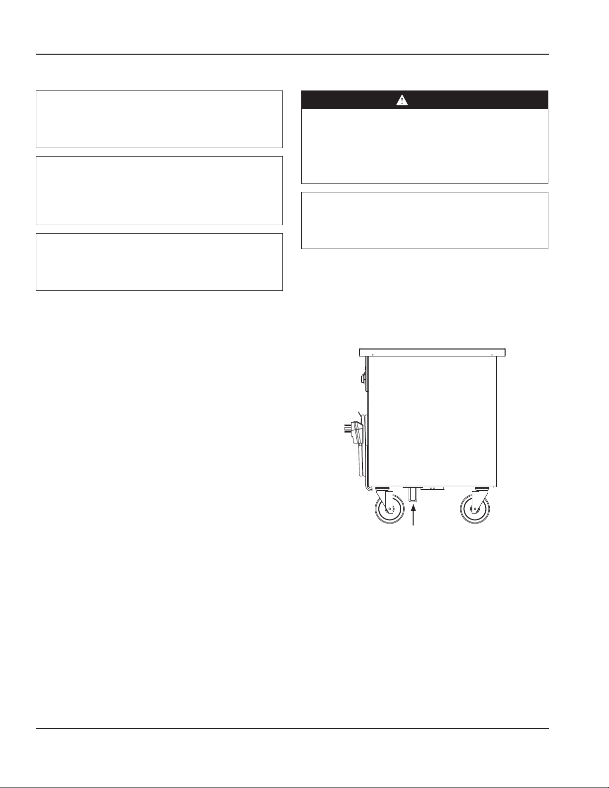
Two anchor points are located on the bottom of each
outdoor unit. Chains must be attached to anchor points to
secure them.
8 Part Number: 9291536 8/14
Page 9

Section 2 Installation
Weight of Equipment
Model Weight
SC-28-NUCRT 120lbs (54kg)
SC-28CRT 165lbs (75kg)
SC-36-NUCRT 160lbs (73kg)
SC-36CRT 185lbs (84kg)
SC-50-NUCRT 180lbs (82kg)
SC-50CRT 205lbs (93kg)
SC-60-NUCRT 210lbs (95kg)
SC-60CRT 240lbs (109kg)
SC-74-NUCRT 240lbs (109kg)
SC-74CRT 270lbs (122kg)
SC-96-NUCRT 280lbs (127kg)
SC-96CRT 310lbs (145kg)
SCF-36CRT 475lbs (215kg)
SCF-50CRT 525lbs (238kg)
SCF-60CRT 575lbs (261kg)
SCF-74CRT 625lbs (283kg)
SCFM-50CRT 500lbs (227kg)
SCFM-74CRT 590lbs (268kg)
SCFT-36-NUCRT 380lbs (172kg)
SCFT-50-NUCRT 455lbs (206kg)
SCFT-60-NUCRT 540lbs (245kg)
SCFT-74-NUCRT 610lbs (277kg)
SCFT-96-NUCRT 680lbs (308kg)
SCI-36-NUCRT 200lbs (91kg)
SCI-36CRT 240lbs (109kg)
SCI-50-NUCRT 245lbs (111kg)
SCI-50CRT 285lbs (129kg)
SCI-60-NUCRT 280lbs (127kg)
SCI-60CRT 320lbs (145kg)
SCI-74-NUCRT 330lbs (150kg)
SCI-74CRT 360lbs (163kg)
SCI-96-NUCRT 380lbs (172kg)
SCI-96CRT 400lbs (181kg)
SCM-36CRT 400lbs (181kg)
SCM-50CRT 450lbs (204kg)
SCM-60CRT 500lbs (227kg)
SCM-74CRT 550lbs (249kg)
SCS-30CRT 180lbs (82kg)
SCS-36CRT 210lbs (95kg)
SCS-50CRT 270lbs (122kg)
SCSC-36-BCRT 350lbs (159kg)
Model Weight
SCSC-36-EFCRT 380lbs (172kg)
SCSC-50-BCRT 425lbs (193kg)
SCSC-50-EFCRT 455lbs (206kg)
SCSC-60-BCRT 500lbs (227kg)
SCSC-60-EFCRT 530lbs (240kg)
SCSC-74-BCRT 575lbs (261kg)
SCSC-74-EFCRT 615lbs (279kg)
SCSC-96-BCRT 650lbs (295kg)
SCSC-96-EFCRT 680lbs (308kg)
SCTS-28CRT 150lbs (68kg)
SCTS-36CRT 192lbs (87kg)
SCU-36-NUCRT 170lbs (77kg)
SCU-36CRT 200lbs (91kg)
SCU-50-NUCRT 190lbs (86kg)
SCU-50CRT 230lbs (104kg)
SCU-60-NUCRT 230lbs (104kg)
SCU-60CRT 270lbs (122kg)
SCU-74-NUCRT 260lbs (118kg)
SCU-74CRT 300lbs (136kg)
SCU-96-NUCRT 300lbs (136kg)
SCU-96CRT 340lbs (154kg)
SH-2-NUCRT 225lbs (102kg)
SH-2CRT 380lbs (172kg)
SH-3-NUCRT 275lbs (125kg)
SH-3CRT 460lbs (209kg)
SH-4-NUCRT 330lbs (150kg)
SH-4CRT 550lbs (249kg)
SH-5-NUCRT 420lbs (191kg)
SH-5CRT 660lbs (299kg)
SH-6-NUCRT 510lbs (231kg)
SH-6CRT 720lbs (327kg)
SH2C-62-NUCRT 350lbs (159kg)
SH2C-74-NUCRT 410lbs (186kg)
SH2C-96-NUCRT 430lbs (195kg)
SH2CR-62-BCRT 575lbs (261kg)
SH2CR-74-BCRT 690lbs (313kg)
SH2CR-96-BCRT 740lbs (336kg)
SH3C-74-NUCRT 420lbs (191kg)
SH3C-96-NUCRT 450lbs (204kg)
SH3CR-96-BCRT 750lbs (340kg)
SH4C-96-NUCRT 450lbs (204kg)
SH4CR-96-BCRT 760lbs (345kg)
Part Number: 9291536 8/14 9
Page 10
Installation Section 2
Model Weight
SHC-50-NUCRT 300lbs (136kg)
SHC-60-NUCRT 350lbs (159kg)
SHC-74-NUCRT 400lbs (181kg)
SHC-96-NUCRT 425lbs (193kg)
SHCR-50-BCRT 475lbs (215kg)
SHCR-60-BCRT 575lbs (261kg)
SHCR-74-BCRT 688lbs (312lkg)
SHCR-96-BCRT 730lbs (331kg)
Clearance Requirements
DANGER
Minimum clearance requirements are the same for
noncombustible locations as for combustible locations.
The flooring under the appliance must be made of a
noncombustible material.
DANGER
Risk of fire/shock. All minimum clearances must be
maintained. Do not obstruct vents or openings.
Notice
Do not block the supply and return air grills or the air
space around the air grills. Keep plastic wrappings,
paper, labels, etc. from being airborne and lodging in
the grills. Failure to keep the air grills clear will result in
unsatisfactory operation of the system.
Notice
Do not position the air intake vent near steam or heat
exhaust of another appliance.
Sides/Back
2.0” (5cm)
Dimensions
Model options may change dimensions.
Model Length Depth Height
SC-28-NUCRT
SC-28CRT
SCTS-28CRT
SCS-30CRT 30” (76cm) 30” (76cm) 38” (97cm)
SC-36-NUCRT
SC-36CRT
SCF-36CRT
SCFT-36-NUCRT
SCI-36-NUCRT
SCI-36CRT
SCM-36CRT
SCS-36CRT
SCSC-36-BCRT
SCSC-36-EFCRT
SCTS-36CRT
SCU-36-NUCRT
SCU-36CRT
SH-2-NUCRT
SH-2CRT
SC-50-NUCRT
SC-50CRT
SCF-50CRT
SCFM-50CRT
SCFT-50-NUCRT
SCI-50-NUCRT
SCI-50CRT
SCM-50CRT
SCS-50CRT
SCSC-50-BCRT
SCSC-50-EFCRT
SCU-50-NUCRT
SCU-50CRT
SH-3-NUCRT
SH-3CRT
SHC-50-NUCRT
SHCR-50-BCRT
SC-60-NUCRT
SC-60CRT
SCF-60CRT
SCFT-60-NUCRT
SCI-60-NUCRT
SCI-60CRT
SCM-60CRT
SCSC-60-BCRT
SCSC-60-EFCRT
SCU-60-NUCRT
SCU-60CRT
SH-4-NUCRT
SH-4CRT
SHC-60-NUCRT
SHCR-60-BCRT
28” (71cm) 30” (76cm) 38” (97cm)
36” (91cm) 30” (76cm) 38” (97cm)
50” (127cm) 30” (76cm) 38” (97cm)
60” (152cm) 30” (76cm) 38” (97cm)
10 Part Number: 9291536 8/14
Page 11

Section 2 Installation
Model Length Depth Height
SH2CR-62-BCRT
SHC2-62-NUCRT
SC-74-NUCRT
SC-74CRT
SCF-74CRT
SCFM-74CRT
SCFT-74-NUCRT
SCI-74-NUCRT
SCI-74CRT
SCM-74CRT
SCSC-74-BCRT
SCSC-74-EFCRT
SCU-74-NUCRT
SCU-74CRT
SH-5-NUCRT
SH-5CRT
SH2C-74-NUCRT
SH2CR-74-BCRT
SH3C-74-NUCRT
SHC-74-NUCRT
SHCR-74-BCRT
SC-96-NUCRT
SC-96CRT
SCFT-96-NUCRT
SCI-96-NUCRT
SCI-96CRT
SCSC-96-BCRT
SCSC-96-EFCRT
SCU-96-NUCRT
SCU-96CRT
SH-6-NUCRT
SH-6CRT
SH2C-96-NUCRT
SH2CR-96-BCRT
SH3C-96-NUCRT
SH3CR-96-BCRT
SH4C-96-NUCRT
SH4CR-96-BCRT
SHC-96-NUCRT
SHCR-96-BCRT
62” (157cm) 30” (76cm) 38” (97cm)
74” (188cm) 30” (76cm) 38” (97cm)
96” (244cm) 30” (76cm) 38” (97cm)
Electrical Service
DANGER
Check all wiring connections, including factory
terminals, before operation. Connections can become
loose during shipment and installation.
DANGER
Copper wire suitable for at least 167°F (75°C) must be
used for power connections.
Warning
n
This appliance must be grounded and all field wiring
must conform to all applicable local and national
codes. Refer to rating plate for proper voltage. It is the
responsibility of the end user to provide the disconnect
means to satisfy the authority having jurisdiction.
VOLTAGE
All electrical work, including wire routing and grounding,
must conform to local, state and national electrical codes.
The following precautions must be observed:
• The equipment must be grounded.
• A separate fuse/circuit breaker must be provided for
each unit.
• A qualified electrician must determine proper wire size
dependent upon location, materials used and length
of run (minimum circuit ampacity can be used to help
select the wire size).
• The maximum allowable voltage variation is ±10% of
the rated voltage at equipment start-up (when the
electrical load is highest).
• Check all green ground screws, cables and wire
connections to verify they are tight before start-up.
Part Number: 9291536 8/14 11
Page 12

Installation Section 2
RATED AMPERAGES, HORSEPOWER & POWER CORD
CHART
DANGER
Units with two power cords must be plugged into
individual branch circuits. During movement, cleaning
or repair it is necessary to unplug both power cords.
Warning
n
This equipment must be positioned so that the plug is
accessible unless other means for disconnection from
the power supply (e.g., circuit breaker or disconnect
switch) is provided.
Important
Due to continuous improvements, this information is
for reference only. Please refer to the equipment serial
plate to verify electrical data. Serial plate information
overrides information listed here.
Units with plugs are supplied with approximately 9ft cords,
maximum 10ft.
Model Voltage, Cycle, Phase Amps HP NEMA Plug for
Indoor Use
SC-28-NUCRT
SC-28CRT
SC-36-NUCRT
SC-36CRT
SC-50-NUCRT
SC-50CRT
SC-60-NUCRT
SC-60CRT
SC-74-NUCRT
SC-74CRT
SC-96-NUCRT
SC-96CRT
SCF-36CRT
SCF-50CRT
SCF-60CRT
SCF-74CRT
SCFM-50CRT 115 V, 60 Hz, 1 Ph 7.1 1/4 5-15P 320P4W
SCFM-74CRT 115 V, 60 Hz, 1 Ph 8.0 1/3 5-15P 320P4W
SCFT-36-NUCRT
SCFT-50-NUCRT
SCFT-60-NUCRT
SCFT-74-NUCRT
SCFT-96-NUCRT
NA NA NA NA NA
115 V, 60 Hz, 1 Ph 7.1 1/4 5-15P 320P4W
115 V, 60 Hz, 1 Ph 8.0 1/3 5-15P 320P4W
115 V, 60 Hz, 1 Ph 7.0 1/4 5-15P NA
Pin & Sleeve Plug
for Outdoor Use
(IEC 60309)
12 Part Number: 9291536 8/14
Page 13

Section 2 Installation
Model Voltage, Cycle, Phase Amps HP NEMA Plug for
Indoor Use
SCI-36-NUCRT
SCI-36CRT
SCI-50-NUCRT
SCI-50CRT
SCI-60-NUCRT
SCI-60CRT
SCI-74-NUCRT
SCI-74CRT
SCI-96-NUCRT
SCI-96CRT
SCM-36CRT
SCM-50CRT
SCM-60CRT
SCM-74CRT
SCS-30CRT
SCS-36CRT
SCS-50CRT
SCSC-36-BCRT
SCSC-36-EFCRT
SCSC-50-BCRT
SCSC-50-EFCRT
SCSC-60-BCRT
SCSC-60-EFCRT
SCSC-74-BCRT
SCSC-74-EFCRT
SCSC-96-BCRT
SCSC-96-EFCRT
SCTS-28CRT
SCTS-36CRT
SCU-36-NUCRT
SCU-36CRT
SCU-50-NUCRT
SCU-50CRT
SCU-60-NUCRT
SCU-60CRT
SCU-74-NUCRT
SCU-74CRT
SCU-96-NUCRT
SCU-96CRT
SH-2-NUCRT 120/208-230 V, 60 Hz, 1 Ph 11.0 NA 14-20P 420P12W
SH-2CRT 120/208-230 V, 60 Hz, 1 Ph 15.0 NA 14-20P 420P12W
SH-3-NUCRT 120/208-230 V, 60 Hz, 1 Ph 16.0 NA 14-20P 420P12W
SH-3CRT 120/208-230 V, 60 Hz, 1 Ph 20.0 NA 14-30P 430P12W
SH-4-NUCRT 120/208-230 V, 60 Hz, 1 Ph 22.0 NA 14-30P 430P12W
SH-4CRT 120/208-230 V, 60 Hz, 1 Ph 26.0 NA 14-50P 460P12W
SH-5-NUCRT 120/208-230 V, 60 Hz, 1 Ph 28.0 NA 14-50P 460P12W
SH-5CRT 120/208-230 V, 60 Hz, 1 Ph 31.0 NA 14-50P 460P12W
SH-6-NUCRT 120/208-230 V, 60 Hz, 1 Ph 33.0 NA 14-50P 460P12W
SH-6CRT 120/208-230 V, 60 Hz, 1 Ph 37.0 NA 14-50P 460P12W
NA NA NA NA NA
115 V, 60 Hz, 1 Ph 7.0 1/4 5-15P 320P4W
NA NA NA NA NA
115 V, 60 Hz, 1 Ph 7.0 1/4 5-15P 320P4W
NA NA NA NA NA
Pin & Sleeve Plug
for Outdoor Use
(IEC 60309)
Part Number: 9291536 8/14 13
Page 14
Installation Section 2
Model Voltage, Cycle, Phase Amps HP NEMA Plug for
Indoor Use
SH2C-62-NUCRT
SH2C-74-NUCRT
SH2C-96-NUCRT
SH2CR-62-BCRT 120/208-230 V, 60 Hz, 1 Ph 16.0 1/4 14-20P 420P12W
SH2CR-74-BCRT
SH2CR-96-BCRT
SH3C-74-NUCRT
SH3C-96-NUCRT
SH3CR-96-BCRT 120/208-230 V, 60 Hz, 1 Ph 23.0 1/4 14-30P 430P12W
SH4C-96-NUCRT 120/208-230 V, 60 Hz, 1 Ph 22.0 NA 14-30P 430P12W
SH4CR-96-BCRT 120/208-230 V, 60 Hz, 1 Ph 29.0 1/4 14-50P 460P12W
SHC-50-NUCRT
SHC-60-NUCRT
SHC-74-NUCRT
SHC-96-NUCRT
SHCR-50-BCRT
SHCR-60-BCRT
SHCR-74-BCRT
SHCR-96-BCRT
Option Voltage, Cycle, Phase Amps HP
N8630 120 V, 60 Hz, 1 Ph 25.0 1/4
N8643
N8656
N8669
N8681
N8717-DESP 208-230 V, 60 Hz, 1 Ph 2.4/2.7 NA
N8731-DESP 208-230 V, 60 Hz, 1 Ph 4.8/5.4 NA
N8745-DESP 208-230 V, 60 Hz, 1 Ph 7.2/8.1 NA
N8759-DESP 208-230 V, 60 Hz, 1 Ph 9.6/10.8 NA
N8773-DESP 208-230 V, 60 Hz, 1 Ph 12.0/13.5 NA
N8787-DESP 208-230 V, 60 Hz, 1 Ph 14.4/16.2 NA
120/208-230 V, 60 Hz, 1 Ph 11.0 NA 14-20P 420P12W
120/208-230 V, 60 Hz, 1 Ph 18.0 1/4 14-30P 430P12W
120/208-230 V, 60 Hz, 1 Ph 16.0 NA 14-20P 420P12W
120 V, 60 Hz, 1 Ph 9.0 NA 5-15P 320P4W
120 V, 60 Hz, 1 Ph 16.0 1/4 5-20P 320P4W
120/240 V, 60 Hz, 1 Ph 21.0 1/4
120/240 V, 60 Hz, 1 Ph 42.0 1/4
120/240 V, 60 Hz, 1 Ph 42.0 1/3
240 V, 50 Hz, 1 Ph 2.1 NA
240 V, 50 Hz, 1 Ph 4.2 NA
240 V, 50 Hz, 1 Ph 6.3 NA
240 V, 50 Hz, 1 Ph 8.4 NA
240 V, 50 Hz, 1 Ph 10.5 NA
240 V, 50 Hz, 1 Ph 12.6 NA
Pin & Sleeve Plug
for Outdoor Use
(IEC 60309)
14 Part Number: 9291536 8/14
Page 15

Section 2 Installation
Drain Connections
Warning
n
Moisture collecting from improper drainage can create a
slippery surface on the floor and a hazard to employees.
It is the owner’s responsibility to provide a container or
outlet for drainage.
Warning
n
If a refrigerated base does not have a condensate
evaporator supplied, you must connect the condensate
line to a suitable drain. Otherwise, water will collect on
the floor, causing a potentially hazardous situation.
The installer/owner is responsible for the correct drain
connections.
• Standard units on casters will have a bronze faucet that
fits a standard garden hose 0.75 in (19mm).
• Units on legs with optional remote drain valve handle
will have 1.0 in (25 mm) threaded pipe extending from
bottom of unit.
• On standard units, a stainless steel access panel or
hinged louver will be provided for access to drain
connections.
Heat of Rejection
Model BTU/Hour
SC-28-NUCRT
SC-28CRT
SC-36-NUCRT
SC-36CRT
SC-50-NUCRT
SC-50CRT
SC-60-NUCRT
SC-60CRT
SC-74-NUCRT
SC-74CRT
SC-96-NUCRT
SC-96CRT
SCF-36CRT 915
SCF-50CRT 1350
SCF-60CRT 1456
SCF-74CRT 1609
SCFM-50CRT Refrigerator 789
SCFM-74CRT Refrigerator 1199
SCFT-36-NUCRT 435
SCFT-50-NUCRT 595
SCFT-60-NUCRT 717
SCFT-74-NUCRT 827
SCFT-96-NUCRT 921
SCI-36-NUCRT
SCI-36CRT
SCI-50-NUCRT
SCI-50CRT
SCI-60-NUCRT
SCI-60CRT
SCI-74-NUCRT
SCI-74CRT
SCI-96-NUCRT
SCI-96CRT
SCM-36CRT 1114
SCM-50CRT 1190
SCM-60CRT 1328
SCM-74CRT 1535
SCS-30CRT
SCS-36CRT
SCS-50CRT
SCSC-36-BCRT
SCSC-36-EFCRT
SCSC-50-BCRT
SCSC-50-EFCRT
SCSC-60-BCRT
SCSC-60-EFCRT
NA
Freezer 1580
Freezer 2040
NA
NA
1102
1240
1343
Part Number: 9291536 8/14 15
Page 16

Installation Section 2
Model BTU/Hour
SCSC-74-BCRT
SCSC-74-EFCRT
SCSC-96-BCRT
SCSC-96-EFCRT
SCTS-28CRT
SCTS-36CRT
SCU-36-NUCRT
SCU-36CRT
SCU-50-NUCRT
SCU-50CRT
SCU-60-NUCRT
SCU-60CRT
SCU-74-NUCRT
SCU-74CRT
SCU-96-NUCRT
SCU-96CRT
SH-2-NUCRT
SH-2CRT
SH-3-NUCRT
SH-3CRT
SH-4-NUCRT
SH-4CRT
SH-5-NUCRT
SH-5CRT
SH-6-NUCRT
SH-6CRT
SH2C-62-NUCRT
SH2C-74-NUCRT
SH2C-96-NUCRT
SH2CR-62-BCRT 1423
SH2CR-74-BCRT 1102
SH2CR-96-BCRT 1343
SH3C-74-NUCRT
SH3C-96-NUCRT
SH3CR-96-BCRT 1240
SH4C-96-NUCRT NA
SH4CR-96-BCRT 1102
SHC-50-NUCRT
SHC-60-NUCRT
SHC-74-NUCRT
SHC-96-NUCRT
SHCR-50-BCRT
SHCR-60-BCRT
SHCR-74-BCRT
SHCR-96-BCRT 1240
1423
1487
NA
NA
NA
1102
Option BTU/HourHP
N8681
N8717-DESP NA
N8731-DESP NA
N8745-DESP NA
N8759-DESP NA
N8773-DESP NA
N8787-DESP NA
1138
Option BTU/HourHP
N8630 379
N8643
N8656 758
N8669
569
948
16 Part Number: 9291536 8/14
Page 17

Section 3
Operation
DANGER
Do not operate any appliance with a damaged cord
or plug. All repairs must be performed by a qualified
service company.
DANGER
Never stand on the unit! They are not designed to
hold the weight of an adult, and may collapse or tip if
misused in this manner.
DANGER
Keep power cord AWAY from HEATED surfaces. DO NOT
immerse power cord or plug in water. DO NOT let power
cord hang over edge of table or counter.
Warning
n
Do not use electrical appliances or accessories other
than those supplied by the manufacturer.
Warning
n
Overloading shelves can damage equipment or cause
bodily injury.
Warning
n
The operator of this equipment is solely responsible
for ensuring safe holding temperature levels for all
food items. Failure to do so could result in unsafe food
products for customers.
Warning
n
Do not use electrical appliances inside the food storage
compartment of this appliance.
Warning
n
Damp or wet hands may stick to cold surfaces.
Warning
n
Do not contact moving parts.
Warning
n
The hand sink is to be used for hand washing only, not
for consumption.
Warning
n
All covers and access panels must be in place and
properly secured, before operating this equipment.
Notice
Never use sharp objects or tools to remove ice or frost.
Do not use mechanical devices or other means to
accelerate the defrosting process.
Notice
Units with pans should be operated with pans in place.
Operating the unit without all pans in place will lower
efficiency and may damage the unit.
Notice
Continuous opening and closing of the doors will
hamper the unit’s ability to maintain optimum
refrigeration temperature. Top section is not intended
for overnight storage. Product should be removed from
pans. Pans can remain in unit while empty.
Notice
Do not place hot pans on/against the blue ABS liner. Do
not throw items into the storage area. Failure to follow
these recommendations could result in damage to the
interior of the cabinet or to the blower coil. Overloading
the storage area, restricting the airflow, and continuous
opening and closing of the doors and drawers will
hamper the unit’s ability to maintain operational
temperature.
Notice
Do not throw items into the storage area. Failure to
heed this recommendation could result in damage to
the interior of the cabinet or to the blower coil.
Warning
n
Use caution when handling metal surface edges of all
equipment.
Part Number: 9291536 8/14 17
Page 18

Operation Section 3
Controls/Programming/Settings
FROST TOP CARTS
Frost tops are designed to maintain an even layer of frost to
pleasantly display product. Once turned on, the compressor
will run continuously. There is no temperature control. The
ON/OFF switch is the only means available to cycle the unit.
Since it takes time for the frost to accumulate initially, the
unit should be turned on approximately one hour before
it is actually required. Product should not be placed on the
frost top prior to turning the unit on, because it may freeze
to the surface of the unit.
The unit must be turned off when not in use or overnight
for defrosting and cleaning.
HEATED AND REFRIGERATED COMBO CARTS
Combo carts are constructed of separate hot and cold wells
with separate controls. Use the refrigerated cart setting
information for the cold portion of the combo cart. Use the
heated cart setting information for the hot portion of the
combo cart.
REFRIGERATED CARTS
Mechanically cooled and LiquiTec series cold pans are
adjusted at the factory to provide proper operation without
any further adjustments.
It may become necessary to adjust the temperature.
Temperature in a mechanically cooled pan is controlled by
a pressure control, see page 23. LiquiTec cold pans have
a thermostat located in the machine compartment. Turn
the knob clockwise as indicated on the control. Settings
are from 1 thru 7 (7 being the coldest). Adjustments should
be made gradually. Several small adjustments will be more
effective than one large adjustment. It may take an hour or
longer to realize the temperature change depending on the
application and location of the unit.
If the mechanical cold pan is to be used with ice, it is
recommended that the optional perforated bottoms be
used. These will allow ice to melt properly.
LiquiTec cold pans are not intended to be used with ice.
Turn LiquiTec cold pans ON an hour prior to use to allow for
ample cool down time.
These units are not designed to cool warm food products.
Items should be placed in the unit cooled at least to the
desired holding temperature, if not slightly colder. In some
applications, a gradual warming of product may occur,
particularly at the exposed top of the products. Stirring
or rotation of the product is necessary to maintain overall
temperature. Warming of food product can occur very
quickly outside of the unit. When loading or rotating the
product, avoid leaving food items in a non-refrigerated
location for any length of time to prevent warming or
spoilage. To ensure product quality product must be
rotated every four hours. Always place covers on pans when
not serving to maintain temperatures.
The unit must be turned off when not in use or overnight
for defrosting and cleaning.
18 Part Number: 9291536 8/14
Page 19

Section 3 Operation
HEATED CARTS
Select desired temperature by rotating the knob on the
temperature control panel. Indicator light will come on
when the switch is activated. Individual temperature
control knobs and indicator lights are provided for each
heated food well.
If the same temperature settings for each well are used
every day, the temperature knobs can be left in their set
position and the wells can be turned off using the ON/OFF
switch at the end of the control panel.
Before the unit is used the first time for serving, turn the
temperature knob to “10” and heat the well for 15 minutes.
Do not be alarmed if smoke appears; this preheat should
burn off any residue or dust that has adhered to the food
well element.
When serving thick sauces always use the hot food well in
“wet” operation. This provides more uniform temperature
for the sauce. Product temperature should range from
140˚F to 160˚F.
Caution
,
Never place food directly in well. Always use pans.
Heated Carts Dry Operation - 1000 Watt
Warning
n
When hot wells operated dry, the well bottoms become
very hot. Do not allow unprotected skin to contact any
well surface.
The heated units may be operated without water with no
damage to the unit. Wet operation is usually much more
efficient and is usually preferred.
When operated dry, the bottom of the well will discolor. To
clean, use a stainless steel cleaner or mild abrasive.
Optional Heated Understorage
If necessary, preheat the heated understorage to desired
temperature. Temperature range of understorage is 100°F
to 200°F (38°C to 93°C). The temperature control knob is
always the far left knob on the panel. Indicator light is also
at the far left.
For most efficient operation, keep covered insets empty
in each well during preheating and when the well is not in
use.
Always place covers on pans when not serving to maintain
temperatures, prevent food from drying out and to reduce
your operating costs.
Heated Carts Wet Operation
Warning
n
Steam can cause serious burns. Always wear some type
of protective covering on your hands and arms when
removing lids from the unit. Lift the lid in a way that will
direct escaping steam away from your face and body.
Water temperature will average 180°F (82.2°C).
Fill the food well with about 2 in (51mm) of water and cover
with lid or empty pan. To preheat water, set temperature
control at “High”. With pans in place, wells will boil water.
Food temperature will vary depending on type and
amount of product. To minimize steam and water usage,
set control to lowest setting that will maintain proper food
temperature.
To reduce preheating time, use hot water to fill the well.
Part Number: 9291536 8/14 19
Page 20

Operation Section 3
MILK AND ICE CREAM CARTS
To begin operation plug the electrical supply cord into a
receptacle with the correct voltage. Each combination unit
is constructed with two separate tanks. Follow the milk cart
and the ice cream cart directions respectively for loading
and defrosting.
The milk tank is set at the factory to maintain temperatures
between 36°F and 40°F (2°C and 4°C). No further adjustment
should be necessary. If a temperature adjustment is
necessary the milk tank temperature is controlled by a
thermostat located in the machine compartment. Turn the
knob clockwise as indicated on the control. Settings are
from 1 thru 7 (7 being the coldest). Adjustments should be
made gradually. Several small adjustments will be more
effective than one large adjustment. It may take an hour
or longer to realize the temperature change depending on
the application and location. The ice cream tank is set at
the factory to maintain temperatures between -5°F and 0°F
(-15°C and -18°C). If a temperature adjustment is necessary
follow the pressure control directions on page 23.
MILK CARTS
Milk carts are set at the factory to maintain temperatures
between 36°F and 40°F (2°C and 4°C). No further
adjustment should be necessary. If a temperature
adjustment is necessary follow the pressure control
directions on page 23. To begin operation plug the
electrical supply cord into a receptacle with the correct
voltage.
To load, place a complete layer of cartons or bottles
standing upright on the load tray. Then place a divider tray
on top of this layer, then another layer of cartons or bottles
on this tray, then another tray and another layer, etc. As
each additional tray is loaded, the elevators gradually lower.
The last layer may be placed on top without the use of
another tray. When loading the average tall half pint bottles,
four layers may be loaded into each compartment standing
upright and the fifth layer laying down. Always use covers
when not serving to maintain temperatures.
ICE CREAM CARTS
Ice cream carts are set at the factory to maintain
temperatures between -5°F and 0°F (-15°C and -18°C). No
further adjustments should be necessary. If a temperature
adjustment is necessary follow the pressure control
directions on page 23. To begin operation plug the
electrical supply cord into a receptacle with the correct
voltage.
To load, place two layers of ice cream on the load tray, then
a tray, two additional layers of ice cream, then another
tray, etc. Do not stack ice cream above the frost line on the
interior of the freezer. Always use covers when not serving
to maintain temperatures.
Ice cream carts require defrosting after 0.375 in to 0.5 in
(10mm to 13mm) of frost forming. Never use sharp objects
or tools to clean or scrape ice/frost build up from the
refrigerated cold pans or frost tops. A puncture to the pan
could cause irreparable damage to the refrigeration system.
Important
Use the divider trays provided between each successive
layer of contents to assure the correct balance of the
load and the proper action of the elevating mechanism.
Wire racks, when used, should be loaded completely. When
placing one rack on top of the other, be sure the stacking
lugs are properly aligned.
Milk carts require defrosting after 0.375 in to 0.5 in (10mm
to 13mm) of frost forming. Never use sharp objects or tools
to clean or scrape ice/frost build up from the refrigerated
cold pans or frost tops. A puncture to the pan could cause
irreparable damage to the refrigeration system.
20 Part Number: 9291536 8/14
Page 21

Section 3 Operation
OPTIONAL N8600 HOT/COLD SERIES
Optional N8600 Hot Operation
N8600 Series hot and cold combination pans must be
operated with water in the well for proper hot operation.
Fill well with a minimum of 4 in (102mm) of water. Place
function switch in HOT position to begin heating. Turn
thermostat dial to the desired temperature.
Caution
,
Never use anything other than plain water in the wells
or tank.
Caution
,
When operated at the highest temperature setting, the
top of the unit will become very hot.
To turn unit off, simply move the function switch to OFF
position. Drain water and allow unit to cool before cleaning
or switching to cold operation.
Optional N8600 Cold Operation
Simply place the function switch to the COLD position.
The compressor controller has been factory set and no
temperature adjustment should be necessary. If the cold
pan is to be used with ice, it is recommended that the
optional perforated bottoms be used. These will allow ice to
melt properly.
These units are not designed to cool warm food products.
Items should be placed in the unit cooled at least to the
desired holding temperature, if not slightly colder. In some
applications, a gradual warming of product may occur,
particularly at the exposed top of the product. Stirring or
rotation of the product is necessary to maintain overall
temperature.
Warming of food product can occur very quickly outside
of the unit. When loading or rotating product, avoid
leaving food items in a non-refrigerated location for any
length of time to prevent warming or spoilage. To ensure
product quality product must be rotated every four hours.
Always place covers on pans when not serving to maintain
temperatures.
Optional N8600 Switching From Hot To Cold Operation
1. Place the function switch in the OFF position and drain
out hot water.
2. Allow the unit to cool until it can be safely cleaned.
3. When clean up procedures are complete, unit will be
ready for cold operation. This takes about one hour.
Notice
To assure maximum compressor life, do not switch
from “hot” to “cold” operation without allowing a cool
down period. Never switch from hot to cold operation
while hot water remains in the pans. Failure to observe
this warning will greatly reduce compressor life and
eventually cause premature compressor failure.
Optional N8600 Switching From Cold To Hot Operation
No special procedure is required to switch from the cold to
hot operation. Be certain to fill will with a minimum of 4 in
(102mm) of water.
Caution
,
The unit is designed so that the compressor and the
heating elements cannot operate at the same time.
Continued operation of the compressor in the “hot
position” is not normal.
The unit must be turned off when not in use or overnight
for defrosting and cleaning.
N8600 Immersion Heater High Limit
As a safety feature, the N8600 food well immersion heater
includes a high limit safety switch. If the heater gets too
hot the safety switch will trip and turn the heater off. A
pilot light on the control panel will illuminate when the
safety switch is tripped. To reset the safety switch, first turn
OFF the thermostat or Power switch and then determine
if low water is the cause. If low water is not the cause,
contact service for resolution. If low water is the cause,
carefully remove food pans and refill the water. This will
allow the immersion heater to cool and the safety switch
will automatically reset. The unit must be turned OFF
as directed or safety switch will not reset even if water
is refilled to proper level. Replace food pans and turn
thermostat or Power switch back on.
Part Number: 9291536 8/14 21
Page 22

Operation Section 3
OPTIONAL N8700DESP SERIES
These units are designed to hold warm food product
between 140ºF to 160ºF (60ºC to 71ºC).
N8700-DESP series individually heated hot food units
may be operated “wet” (with water in the wells) or “dry”.
“Dry” operation using 4 in (102mm) deep pans produces
optimum performance.
A power switch and digital control are provided for each
individual heated food well. After the unit is hard wired to
the electrical system, turn the power switch ON and the
digital display will read OFF. Press Set and then use the
arrows to select the desired temperature setting (1-10). The
new temperature setting is entered three seconds after the
last button is pressed. When the power switch is used to
turn the well OFF and back ON the temperature setting will
remain.
Caution
,
Never place food directly in well. Always use pans.
For most efficient operation, keep covered inserts in each
well during preheating or when empty.
Always place covers on pans when not serving to maintain
temperatures and prevent food from drying out.
Optional N8700 Wet Operation
Fill the food well with a minimum of 2 in (51mm) of water
and cover with lid or empty pan. To preheat water, set
temperature control at 3. With pans in place, wells will boil
water. Food temperature will vary depending on type and
amount of product. To minimize steam and water usage,
set control at lowest setting that will maintain proper food
temperature. To reduce preheating time, use hot water to
fill the well. Preheating time with room temperature water
is one hour.
Optional N8700 Temperature Control
LOAD
SET
• LED Display: Indicates the temperature setting 0-10. At
the first startup the display will read OFF.
• SET: When SET is depressed, the temperature setting is
displayed and can be adjusted with the arrows.
• LOAD Light: Lit when well is heating.
• Arrows: After pressing SET, press the Up-Arrow to
increase the temperature setting, press the DownArrow to decrease the temperature setting. The new
temperature setting is entered three seconds after the
last arrow is pressed.
Caution
,
Never use anything other than plain water in the wells
or tank.
Caution
,
When operated at the highest temperature setting, the
top of the unit will become very hot.
Optional N8700 Dry Operation
Dry operation is more efficient and is preferred.
When operated dry, the bottom of the well will discolor. To
clean, use a stainless steel cleaner or mild abrasive.
22 Part Number: 9291536 8/14
Page 23

Section 3 Operation
Sound System
1
5
4
1. Open the sound system control area.
2. Flip off the port cover.
3. The USB port is for charging purposes. Connect your
device to the USB for power.
4. Plug the audio into the AUX port.
5. Turn the power switch ON.
6. Control the audio, including volume, with the
connected device.
3
2
Operational Checks
PRESSURE CONTROL
The models below have an adjustable pressure control
that controls the temperature. It is located in the machine
compartment. They are field adjustable and do not require
a service agent. The adjustable control has the word
COLDER near the knob, with an arrow to indicate the
adjustment direction. Make small incremental adjustments
if a temperature adjustment is necessary.
Caution
,
In attempting to adjust the pressure control, you can
do damage to your unit by accidentally adjusting the
differential.
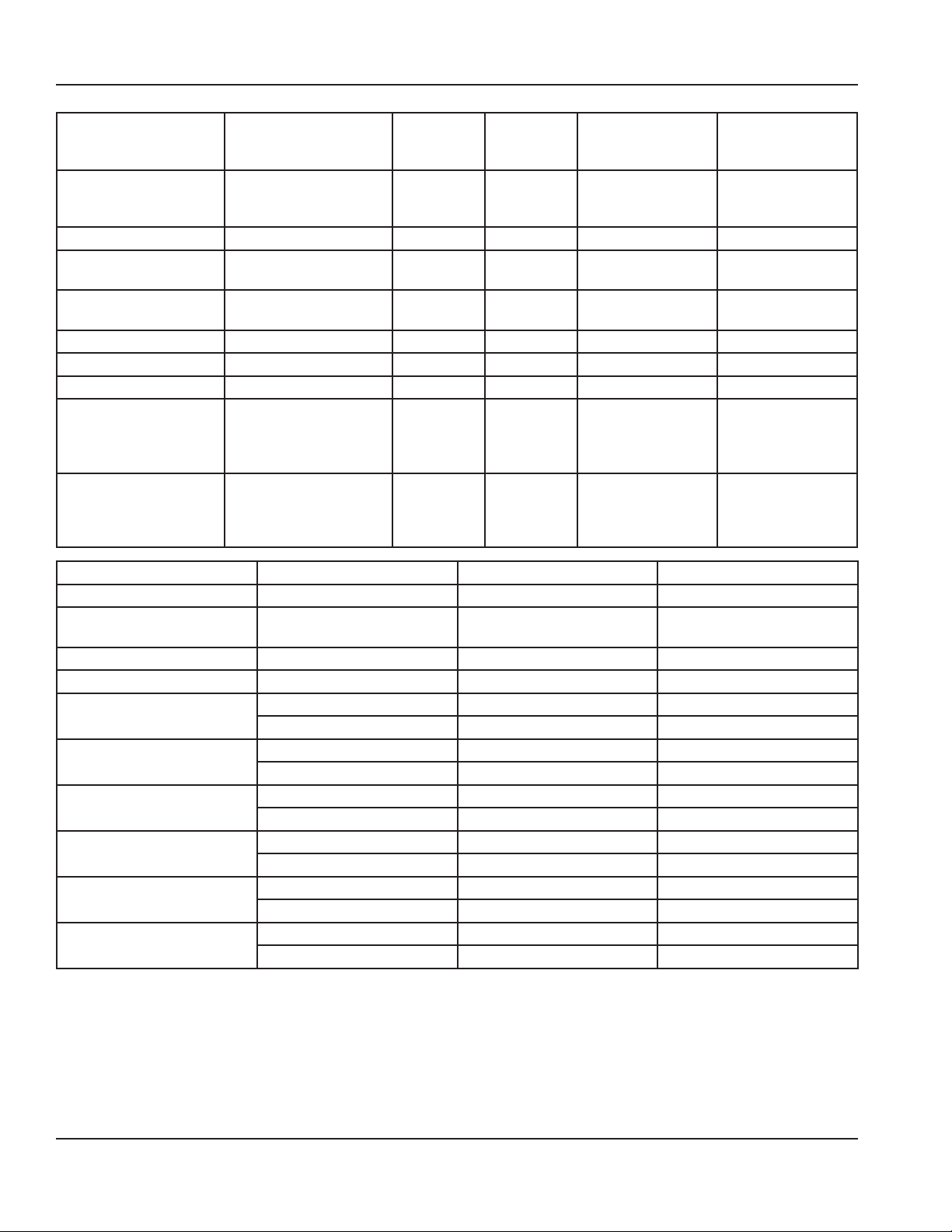
Model Cut-In Differential
Ice Cream Carts
SCF-CRT & SCFM-CRT
Milk Carts
SCM-CRT
Cold Pan Carts
SCSC-BCRT & SHCR-BCRT
30# 15#
80# 30#
55# 30#
(Knob Controlled)
Dierential
Cut In
Part Number: 9291536 8/14 23
Page 24

Operation Section 3
THIS PAGE INTENTIONALLY LEFT BLANK
24 Part Number: 9291536 8/14
Page 25

Section 4
Maintenance
Cleaning and Sanitizing Procedures
GENERAL
Warning
n
When using cleaning fluids or chemicals, rubber gloves
and eye protection (and/or face shield) must be worn.
You are responsible for maintaining the equipment
in accordance with the instructions in this manual.
Maintenance procedures are not covered by the warranty.
Maintenance Daily Weekly Monthly
Interior X X X
Gasket X X X X
Exterior X X X
Glass Surfaces X X X
Counter Protector
Hardware
Drain X X X
Condenser Coil X X X
Casters X X X
INTERIOR CLEANING
X X X
EXTERIOR CLEANING
Notice
When cleaning interior and exterior of unit, care should
be taken to avoid the front power switch and the rear
power cord. Keep water and/or cleaning solutions away
from these parts.
Notice
Never use a high-pressure water jet for cleaning or hose
down or flood interior or exterior of units with water. Do
not use power cleaning equipment, steel wool, scrapers
or wire brushes on stainless steel or painted surfaces.
The interior can be cleaned using soap and warm water. If
this isn’t sufficient, try ammonia and water or a nonabrasive
liquid cleaner.
Never use an acid based cleaning solution on exterior
panels! Many food products have an acidic content,
which can deteriorate the finish. Be sure to clean the
stainless steel surfaces of ALL food products.
Clean the area around the unit as often as necessary to
maintain cleanliness and efficient operation.
Wipe gasket and surfaces with a damp cloth rinsed in water
to remove dust and dirt from the outside of the unit. Always
rub with the “grain” of the stainless steel to avoid marring
the finish. If a greasy residue persists, use a damp cloth
rinsed in a mild dish soap and water solution. Wipe dry with
a clean, soft cloth.
Never use steel wool or abrasive pads for cleaning. Never
use chlorinated, citrus based or abrasive cleaners.
Fiberglass and stainless steel exterior panels have a clear
coating that is stain resistant and easy to clean. Products
containing abrasives will damage the coating and
scratch the panels. Daily cleaning may be followed by an
application of stainless steel cleaner or polish which will
After Prolonged
Shutdown
Notice
At Start-Up
Part Number: 9291536 8/14 25
Page 26

Maintenance Section 4
eliminate water spotting, fingerprints and bring out the
color of the fiberglass. Fiberglass surfaces should be waxed
twice a year. Early signs of stainless steel breakdown are
small pits and cracks. If this has begun, clean thoroughly
and start to apply stainless steel cleaners in attempt to
restore the steel.
COUNTER PROTECTOR GLASS & HARDWARE CLEANING
Notice
Never use window sprays or kitchen scouring
compounds to clean plexiglas.
Clean daily with soap and water. Extreme stains or grease
should be cleaned with a nonabrasive cleaner and plastic
scrub pad. Polish the chrome when necessary with a soft
cotton cloth.
DRAIN
Each unit has a drain located inside the unit that removes
the condensation from the evaporator coil and routes it
to an external condensate evaporator pan. Each drain can
become loose or disconnected during normal use. If you
notice water accumulation on the inside of the unit, be sure
the drain tube is connected to the evaporator drain pan. If
water is collecting underneath the unit, make sure the end
of the drain tube is in the condensate evaporator in the
machine compartment. The leveling of the unit is important
as the units are designed to drain properly when level. Be
sure all drain lines are free of obstructions.
CLEANING THE CONDENSER COIL
In order to maintain proper refrigeration performance, the
condenser fins must be cleaned of dust, dirt and grease
regularly. It is recommended that this be done monthly. If
conditions are such that the condenser is totally blocked
in a month, the frequency of cleaning should be increased.
Clean the condenser with a vacuum cleaner or stiff brush. If
extremely dirty, a commercially available condenser cleaner
may be required.
Failure to maintain a clean condenser coil can initially cause
high temperatures and excessive run times. Continuous
operation with a dirty or clogged condenser coil can
result in compressor failure. Neglecting the condenser coil
cleaning procedures will void any warranties associated
with the compressor and cost to replace the compressor.
DEFROSTING
Refrigerated cold pans and frost tops should be defrosted
daily. Milk or Ice Cream dispensers require defrosting after
0.375” to 0.5” (10 mm to 13 mm) of frost forming. ON/OFF
switch is located above louver panel.
Caution
,
Never use sharp objects or tools to clean or scrape ice/
frost buildup from the refrigerated cold pans or frost
tops. A puncture to the pan could cause irreparable
damage to the refrigeration system.
Units with a Eutectic Fluid Cold Pan require the same
precautions. The fluid is NOT refillable and loss of fluid
due to a puncture would cause irreparable damage.
DOORS/HINGES
Over time and with heavy-use doors, the hinges may
become loose. If this happens, tighten the screws that
mount the hinge brackets to the frame of the unit. Loose
or sagging doors can cause the hinges to pull out of the
frame, which may damage both the doors and the hinges.
In some cases this may require qualified service agents or
maintenance personnel to perform repairs.
PREVENTING BLOWER COIL CORROSION
To help prevent corrosion of the blower coil, store all acidic
items, such as pickles and tomatoes, in seal-able containers.
Immediately wipe up all spills.
FIELD INSTALLATION
Over shelves and other items mounted to the top of the
counters should never be installed in the field due to the
potential damage to the refrigeration system.
CASTERS
Wipe casters with a damp cloth monthly to prevent
corrosion.
26 Part Number: 9291536 8/14
Page 27

Section 4 Maintenance
Winterizing Optional Sink
Failure to perform the winterizing process will void the
warranties.
Waste
Water
Tank
Waste
Water Tank
Connection
Fresh
Water
Tank
Fresh
Water Tank
Connection
FLUSHING THE RV ANTIFREEZE AFTER WINTERIZING
1. Fill the fresh water tank.
2. Turn on hot water at faucet to circulate fresh water
through hot water system to purge all RV antifreeze.
3. Turn off hot water at faucet.
4. Turn on cold water at faucet to circulate fresh water
through cold water system to purge all RV antifreeze.
5. Turn off cold water at faucet.
6. Drain waste water tank and re-install.
FOR CONDITIONS WHERE UNIT IS STORED ABOVE 40°F
1. Drain fresh water tank.
2. Drain waste water tank and re-install.
3. Cover unit with the provided black cover.
FOR CONDITIONS WHERE UNIT IS STORED BELOW 40°F
1. Drain fresh water tank.
2. Drain waste water tank and re-install.
3. Remove fresh water inlet from fresh water tank.
4. Insert fresh water inlet into RV antifreeze (NEVER USE
AUTOMOTIVE ANTIFREEZE).
5. Turn on hot water at faucet to circulate RV antifreeze
(NEVER USE AUTOMOTIVE ANTIFREEZE) through hot
water system.
6. Turn off hot water at faucet.
7. Turn on cold water at faucet to circulate RV antifreeze
(NEVER USE AUTOMOTIVE ANTIFREEZE) through cold
water system.
8. Turn off cold water at faucet.
9. Drain waste water tank and re-install.
Part Number: 9291536 8/14 27
Page 28

Maintenance Section 4
THIS PAGE INTENTIONALLY LEFT BLANK
28 Part Number: 9291536 8/14
Page 29

Section 5
Troubleshooting
Problem -> Cause -> Correction Chart
Problem Cause Correction
Cabinet not
running
Condensing
unit runs for
long periods or
continuously
Cabinet
temperature is too
high
Cabinet is noisy Loose part(s). Locate and tighten loose part(s).
Fuse blown or circuit breaker tripped. Replace fuse or reset circuit breaker.
Power cord unplugged. Plug in power cord.
Thermostat set too high. Set thermostat to lower temperature.
Main power switch turned off. Turn main power switch on.
Cabinet in defrost cycle.
(Freezer models)
Excessive amount of warm product placed in
cabinet.
Prolonged door openings or door(s) ajar. Make sure door(s) are closed when not in use. Avoid
Door gasket(s) not sealing properly. Check gasket condition. Adjust door or replace gasket if
Dirty condenser coil. Clean the condenser coil.
Evaporator coil iced over. Turn unit off and allow coil to defrost.
Thermostat set too high. Set thermostat to lower temperature.
Poor air circulation in cabinet. Re-arrange product to allow proper air circulation.
Exterior thermometer is out of calibration. Re-calibrate thermometer.
Excessive amount of warm product placed in
cabinet.
Prolonged door openings or door(s) ajar. Make sure door(s) are closed when not in use.
Dirty condenser coil. Clean the condenser coil.
Evaporator coil iced over. Turn unit off and allow coil to defrost.
Allow adequate time for product to cool down.
Allow adequate time for product to cool down.
Wait for defrost cycle to finish.
prolonged door openings.
necessary.
Make sure thermostat is not set too cold.
Also, check gasket condition.
Avoid prolonged door openings.
Make sure thermostat is not set too cold.
Also, check gasket condition.
Refrigerator is
freezing product
Compressor will
not start
Sound system
audio has no
volume
The cart amplifier is turned off or the volume is
Thermostat is set too low. Set thermostat to higher temperature.
Dirty condenser coil. Clean the condenser coil.
Not enough cabinet clearance for proper
refrigeration system operation.
Low voltage to cabinet. Check and correct incoming voltage to cabinet.
turned down.
Move cabinet or make other adjustments to gain proper
cabinet clearances.
Access the cart amplifier in the unit mechanical access with
a screwdriver. The light indicates if it has power. Turn the
volume all the way up.
Part Number: 9291536 8/14 29
Page 30

Troubleshooting Section 5
THIS PAGE INTENTIONALLY LEFT BLANK
30 Part Number: 9291536 8/14
Page 31

Page 32

DELFIELD
980 SOUTH ISABELLA ROAD, MOUNT PLEASANT, MI 48858
800-733-8821
WWW.DELFIELD.COM
Every new piece of Manitowoc Foodservice equipment comes with KitchenCare™ and you choose the level of service that meets
your operational needs from one restaurant to multiple locations.
StarCare – Warranty & lifetime service, certied OEM parts, global parts inventory, performance audited
ExtraCare — CareCode, 24/7 Support, online/mobile product information
LifeCare – Install & equipment orientation, planned maintenance, KitchenConnect™, MenuConnect
Talk with KitchenCare™ • 1-844-724-CARE • www.mtwkitchencare.com
To learn how Manitowoc Foodservice and its leading brands can equip you, visit our global web site at
www.manitowocfoodservice.com, then discover the regional or local resources available to you.
©2014 Manitowoc Foodservice except where explicitly stated otherwise. All rights reserved. Continuing product improvement may necessitate change of specications without notice.
Part Number: 9291536 8/14
 Loading...