

Page 1
™
Delfield
Installation, Use And Care Manual
Please read this manual completely before attempting to install or operate this equipment!
Notify carrier of damage! Inspect all components immediately.
®
Important Information
Read Before Use
Please Save These Instructions!
November 2011
Page 2

Mobile Kiosks Installation, Use And Care Manual
Delfield
Contents
Serial Number Information ........................................................ 2
Receiving And Inspecting Equipment ........................................ 2
Specifications ............................................................................. 3
Important Caution Notes ............................................................3
Initial Setup ................................................................................ 4
Closing the Gullwing .................................................................. 5
Gullwing Component Guide ....................................................... 6
Sink Operation ..........................................................................10
Sink Wiring Diagram ................................................................ 11
Wiring Diagrams ...................................................................... 12
Energy Management Unit ........................................................12
Plumbing .................................................................................. 13
Safety Strut Locks Installation & Usage .................................. 14
Winterizing ...............................................................................16
Maintenance ............................................................................. 18
Serial Number Information
The serial number is on the identification plate that also includes
the model number. The identification plate is located on the left
inside wall of the mechanical section.
Always have the serial number of your unit available when calling
for parts or service.
©2011 The Delfield Company. All rights reserved. Reproduction without
written permission is prohibited. “Delfield” is a registered trademarks of The
Delfield Company.
Trouble Shooting ...................................................................... 20
Replacement Parts ................................................................... 21
Standard Labor Guidelines ......................................................22
Standard Warranty ................................................................... 23
Receiving And Inspecting The Equipment
Even though most equipment is shipped packaged, care
should be taken during unloading so the equipment is not
damaged while being moved into the building.
1. Visually inspect the exterior of the package and skid or
container. Any damage should be noted and reported to
the delivering carrier immediately.
2. If damaged, open and inspect the contents with the
carrier.
3. In the event that the exterior is not damaged, yet upon
opening, there is concealed damage to the equipment
notify the carrier. Notification should be made verbally as
well as in written form.
4. Request an inspection by the shipping company of the
5. Visually inspect the heating package.
6. Freight carriers can supply the necessary damage forms
7. Retain all crating material until an inspection has been
damaged equipment. This should be done within 10 days
from receipt of the equipment.
upon request.
made or waived.
2
For customer service, call (800) 733-8829, (800) 733-8821, Fax (989) 773-3210, www.delfield.com
™
®
Page 3
Mobile Kiosks Installation, Use And Care Manual
Delfield
Specifications
Model V/Hz/Ph Power (Watts) Amps Nema Plug Ship Weight
lbs (kg)
GULL316 120/240V-60Hz-1Ph 9,600 40.0 14-50P 1279 (580)
NF316 120/240V-60Hz-1Ph 9,600 40.0 14-50P 1346 (611)
MINI316 120/60/1 1,440 12.0 5-15P 505 (229)
MINICOF316 120/60/1 1,440 12.0 5-15P 539 (244)
Model Sink
Capacity
WASH1-316 25 gal 5 gal (1) 13 gal 120/60/1 1,440 12.0 5-15P 556 (252)
WASH2-316 (2) 15 gal 5 gal (1) 13 gal 120/60/1 1,440 12.0 5-15P 578 (262)
WASH3-316 (3) 8.5 gal 5 gal (2) 13 gal 120/60/1 1,440 12.0 5-15P 590 (268)
Water Tank
Capacity
Waste
Water Tank
Capacity
V/Hz/Ph Power
(Watts)
Amps Nema Plug Ship Weight
lbs (kg)
Important Caution Notes
•Ensure that the mobile kiosk is only moved and operated on a hard level surface.
•Use the mobile kiosk for its intended purposes only.
•The mobile kiosk is designed to be used both indoors and outdoors.
•If the mobile kiosk is fitted with a water pump, be aware that pressure in water lines can vary.
•When moving the mobile kiosk, use the handles provided at either end.
•Be careful when moving the mobile kiosk.
•Never stand on the unit or its counter extensions. Doing so may result in bodily injury.
•Ensure all doors are closed and in the locked position before moving the mobile kiosk.
•Be cautious of moving parts to avoid injury.
•Failure to follow instructions in this manual can cause property damage, injury and void warranty.
™
®
For customer service, call (800) 733-8829, (800) 733-8821, Fax (989) 773-3210, www.delfield.com
3
Page 4
Mobile Kiosks Installation, Use And Care Manual
Delfield
Initial Set Up
It Is Essential That The Mobile Kiosk Is Only Moved And
Operated On A Hard Level Surface
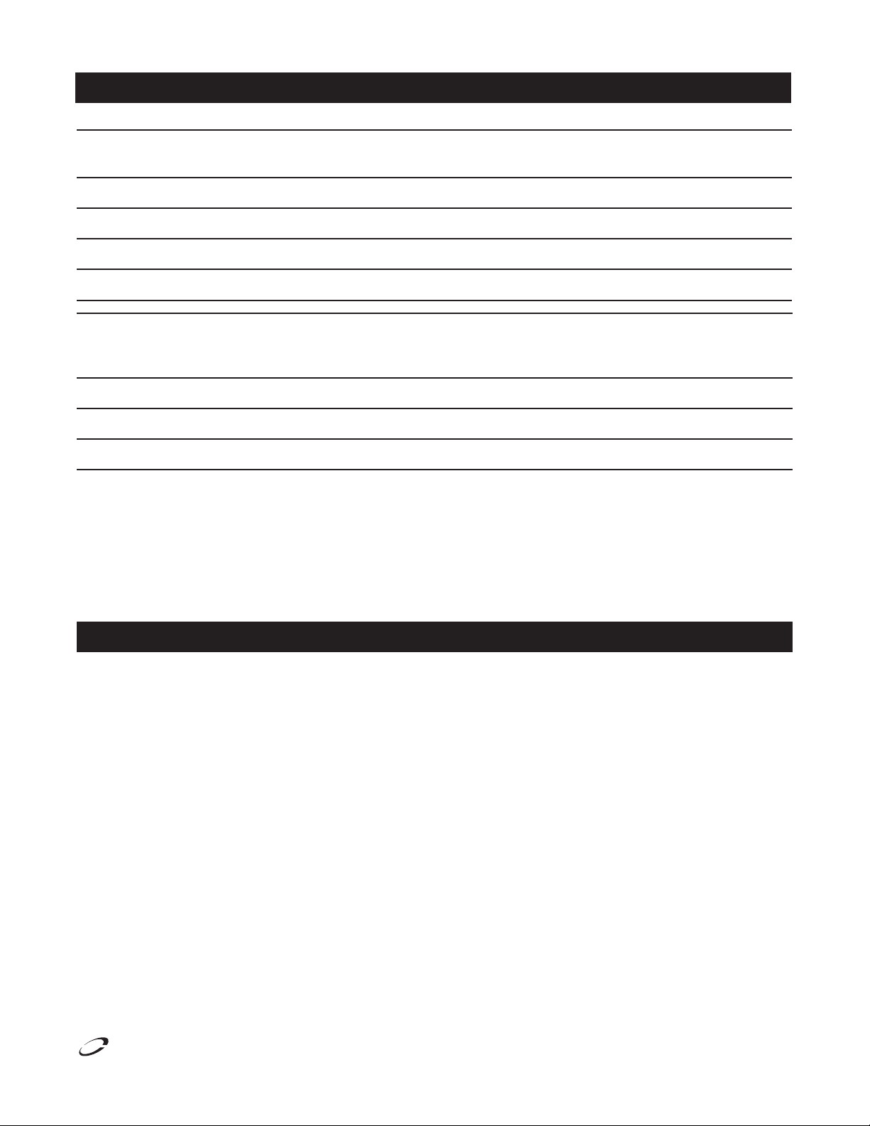
When opening the mobile kiosk for the first time please take
time to follow these steps.
1. Remove the black night cover, to expose the locked/closed
Gullwing.
2. Confirm unit is on a hard level surface. Lock all casters.
3. Using the keys attached to the main handle, unlock the two
main bolt locks and slide open the bolt.
6. Reach over the main service bench to locate and unlock
the 2 bolt locks on the inside of the customer side door.
With care raise the customer side door. Swing safety strut
lock up onto strut.
7. Fold down the customer service shelf.
8. Using the second set of keys provided, unlock the right
or left counter extension door. Hold the door and release
the lock, the door will spring release. While holding the
counter extension door:
a. Pull out the extension support slides. Warning – Fully
Extend Slides Before Lowering Counter Extensions
b. Lower the counter extension into position.
c. Counter extensions can support a maximum of 220lbs
(100kg).
4. Note: Do not allow the Gullwing doors to open
uncontrolled as damage to the mechanism may occur.
Using the main handle, raise the door. Note the door is
installed using gas struts. Once initiated allow the struts
to open the door automatically, keep control of the door
while raising.
5. Swing safety strut lock up onto strut. The lock’s top should
be under the bottom of the strut’s upper section keeping
it from closing. (1) Safety strut lock is required per door.
4
For customer service, call (800) 733-8829, (800) 733-8821, Fax (989) 773-3210, www.delfield.com
™
®
Page 5
Mobile Kiosks Installation, Use And Care Manual
Delfield
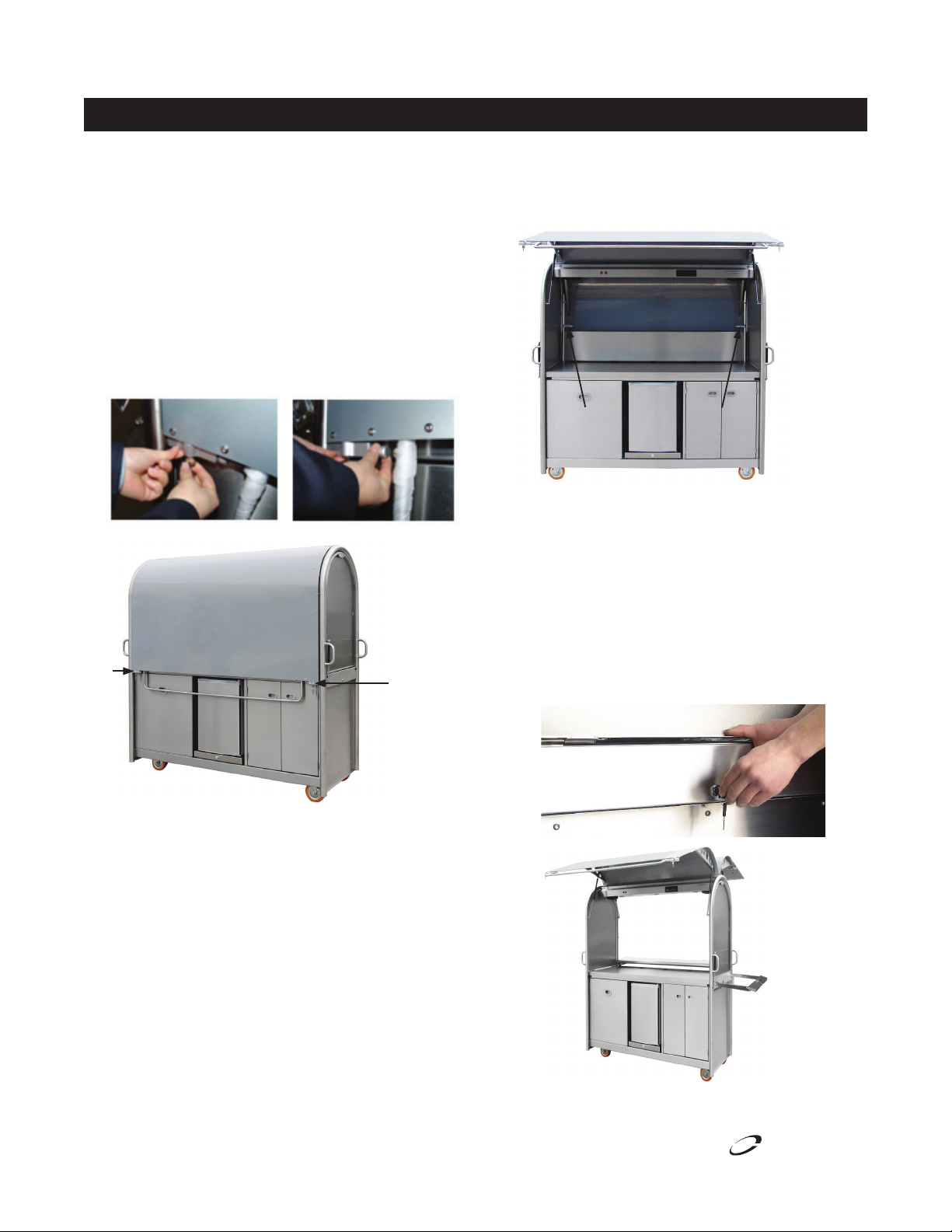
Initial Set Up, continued Closing The Gullwing
9. Repeat Step 8 for the opposite end.
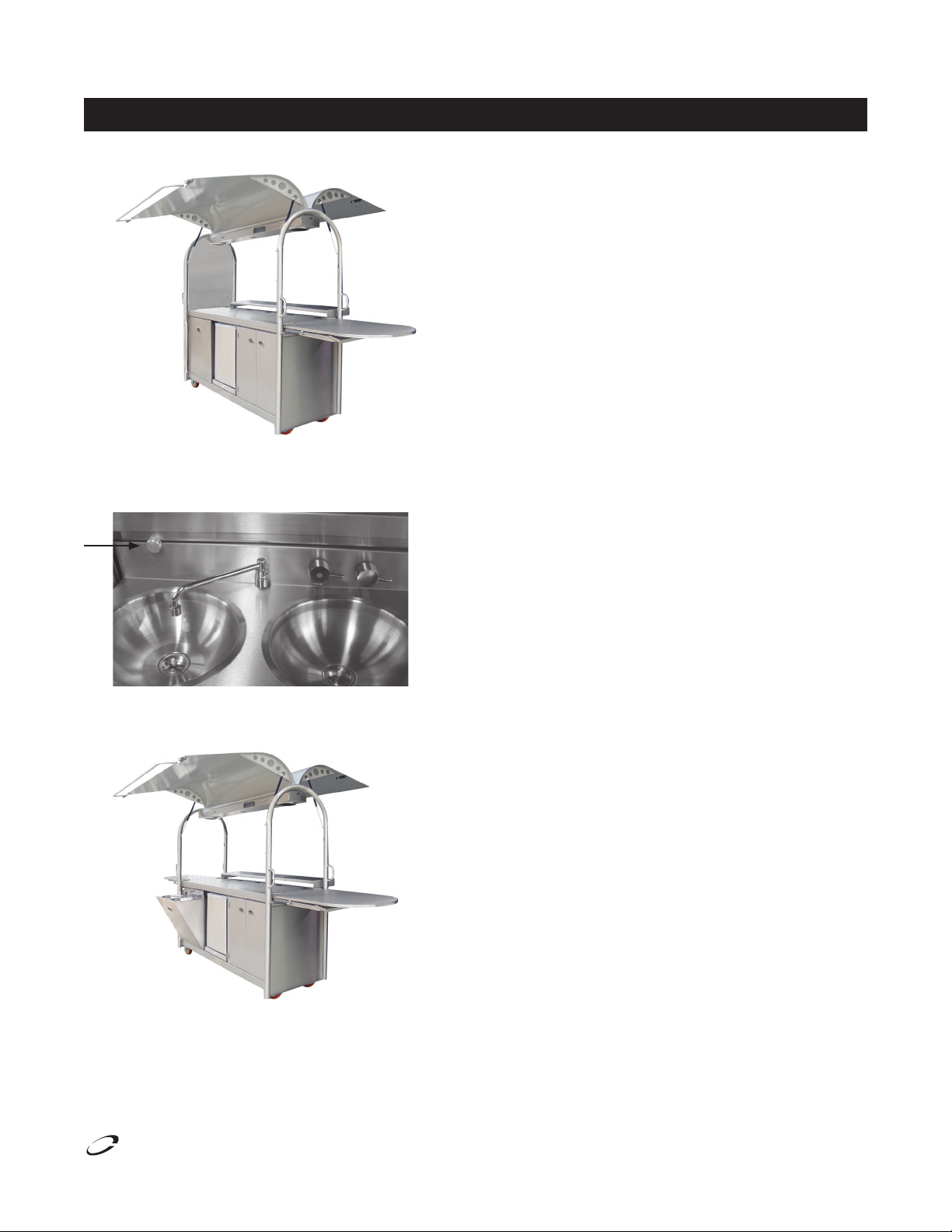
10. Locate and open the two compartment sink using the
recessed handle. Rotate the disk on the backsplash to lock
the sink in the open position.
1. Turn off all appliances, light switches, radio/CD and,
unless refrigeration is required overnight, disconnect the
power source.
2. Allow hot equipment to cool.
3. Empty and clean the waste container.
4. Clean as required.
5. Rotate the disk on the sink backsplash and close the sink.
6. Close and lock the counter extensions.
7. Raise the customer service shelf.
8. Swing safety strut lock down to unlock. Close and lock the
customer side door.
9. Ensure the doors to undercounter modules are closed.
10. Swing safety strut lock down to unlock. Close and lock the
operator’s side door.
11. Clean the exterior.
12. If required, cover the Gullwing.
11. To access the water, drainage and mechanical section
open the left end door.
12. Provide power and water to the unit.
™
®
For customer service, call (800) 733-8829, (800) 733-8821, Fax (989) 773-3210, www.delfield.com
5
Page 6
Mobile Kiosks Installation, Use And Care Manual
Delfield
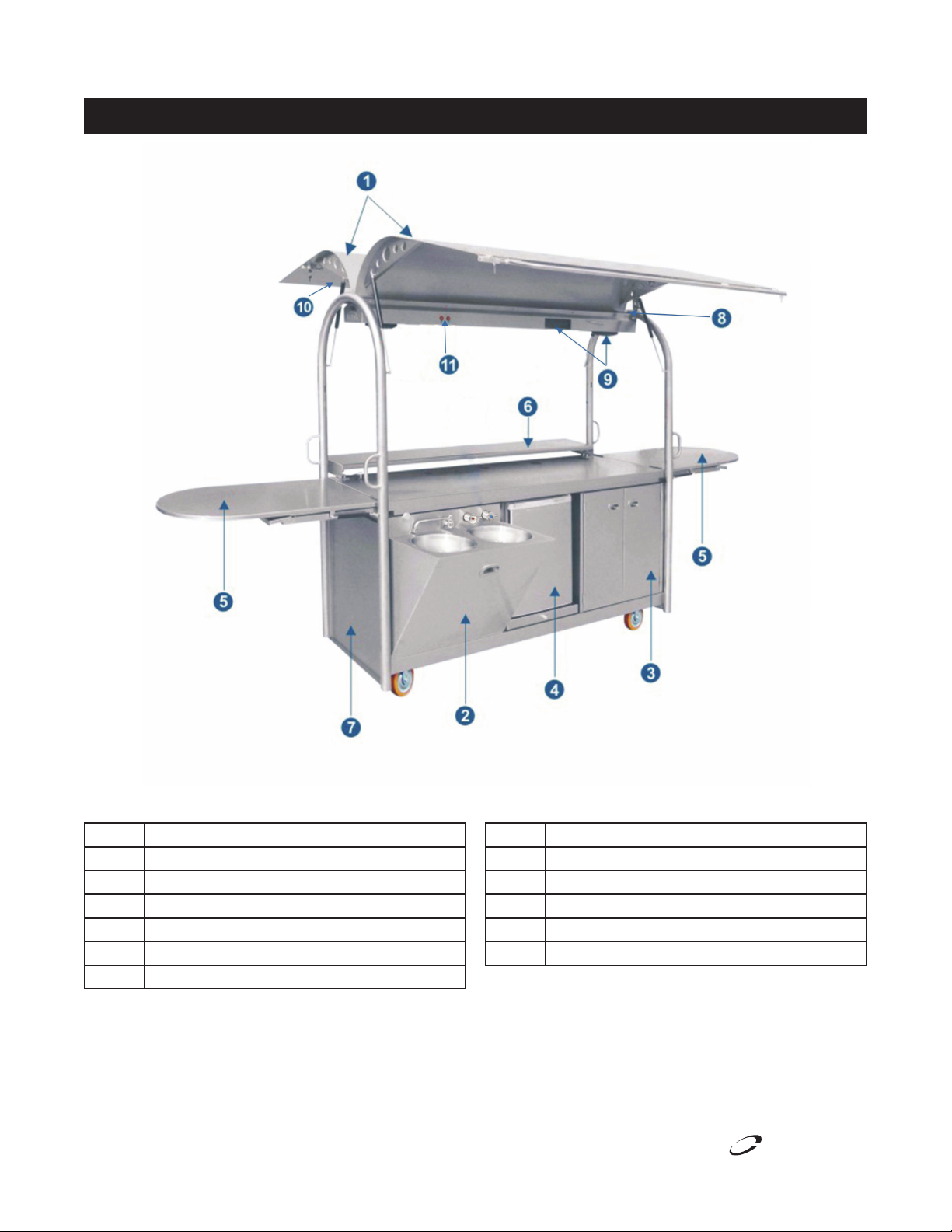
Gullwing Component Guide
Key Description
1 Gullwings
2 Two Compartment Sink
3 Dry Storage Cupboard
4 Refrigerator
5 Counter Extensions
6 Customer Service Shelf
6
For customer service, call (800) 733-8829, (800) 733-8821, Fax (989) 773-3210, www.delfield.com
Key Description
7 Access Door
8 Internal Drainage and Gutter System
9 CD Player and Speakers
10 Menu Board Display
11 Lighting – On/Off Switches
™
®
Page 7
Delfield
Gullwing Component Guide, continued
Mobile Kiosks Installation, Use And Care Manual
Service Module
The Service Module is an enclosed area that is located
immediately behind the sinks and is accessed through a door
at the left lower end of the Gullwing.
The Service Module is equipped to accommodate the following
components:
1. Energy management unit
2. Fresh water tank
3. Waste water tank
4. Water filtration
5. Hot water system
6. Water pump
Energy Management Unit
The Energy Management Unit is located in the Service Module .
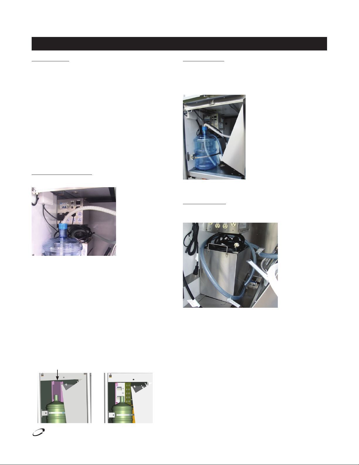
Fresh Water Tank
The Gullwing comes supplied with a standard water tank. The
water tank can simply be refilled or replaced. To remove or
replace, pull the hose out. Be sure to replace and secure the top
cap and hose firmly before operation.
Please note the water tank can be bypassed and plumbed direct
to a water supply.
Waste Water Tank
The Gullwing has been fitted with a waste water tank for your
convenience.
Check that all plugs are correctly connected. The EMU has
spare plugs available for additional equipment to be added on
site.
Identify a suitable power outlet to connect the Energy
Management Unit. North American power requirements for
standard configuration is 120/240V-60Hz-1Ph 40A.
The main power should be supplied to the Mobile Kiosk and can
be channelled to the Energy Management Unit via the cutout in
the base of the service module.
One cannot operate electrical appliances on a Mobile Kiosk
if power is not available. The Energy Management Unit isn’t
designed to provide power, but rather distribute it, power must
be available at the site.
This bracket is for hanging the energy management unit.
™
®
For customer service, call (800) 733-8829, (800) 733-8821, Fax (989) 773-3210, www.delfield.com
Please note the waste water tank can be bypassed and plumbed
direct to main drainage.
7
Page 8
Mobile Kiosks Installation, Use And Care Manual
Delfield
Gullwing Component Guide, continued
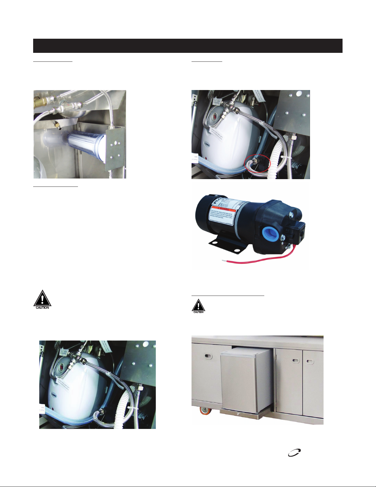
Water Filtration
The Gullwing is fitted with a water filter, located in the service
module in the right corner of the food vending unit. Check that
the waste water tank hose is connected and without kinks.
Hot Water System
The Gullwing has been fitted with a hot water heater. It is
installed at the factory and plumbed to the internal water
system/filter/pump and also connected to the electrical supply.
Please ensure these connections have not been effected during
transit and that all hoses connections are free of kinks.
Double check water and waste connections for:
•Hot water system
•Water filter
•12volt water pump
Turn on the water heater and allow water to flow until air has
escaped the plumbing system and the flow is constant.
Allow approximately twenty minutes to heat the hot
water system and then open each tap on the food
vending unit to check water flow. This will release
any air in the system. Do not let the water heater run
without water. This will damage the unit and void
warranty.
Water Pump
The Gullwing has a water pump installed to control the water
system within the unit. Additional pumps may need to be added
for items such as coffee machines.
When plumbing directly to main water, please unscrew the inlet
pipe at the end of water pump and connect it to main water.
Optional Central Refrigerator
This refrigerator/freezer option is intended for indoor
use only.
Centrally located on the operator side, the refrigerator is
installed on a slide for ease of cleaning.
8
Note: The refrigerator can be replaced with a freezer for your
required application.
For customer service, call (800) 733-8829, (800) 733-8821, Fax (989) 773-3210, www.delfield.com
™
®
Page 9

Delfield
Gullwing Component Guide, continued
Mobile Kiosks Installation, Use And Care Manual
Dry Storage Cupboard
The dry storage cupboard is located on the right third of the
Gullwing. The dry storage cupboard is equipped with a locking
cash drawer and data cable.
Food Vending Unit
The Food Vending Unit is one of the key features on the
Gullwing, providing the following:
•Two sinks
•Fresh water tank
•Waste water tank
•Water filtration
•Hot water system
•Water pumps
•Manifolds for controlling waste water
The equipment in the food vending unit can be accessed via the
Service Module.
Opening Food Vending Unit
1. Standing in front of the Food Vending Unit, pull it out using
the centrally located handle.
2. Rotate the disc on the backsplash to lock the unit in the
open position.
3. Check that the waste water tank is empty and the drain
hose is properly connected.
4. Check the fresh water tank is full
5. Check that the power supply is connected and sufficient
time has elapsed to heat the hot water system.
6. Turn the cold tap for cold water (right tap) Turn the hot tap
for hot water (left tap)
Closing Food Vending Unit
1. Hold the centrally located handle with one hand
2. Rotate the disc on the backsplash to unlock the Food
Vending Unit
3. Allow it to slowly close
4. Caution must be taken not to trap hands or fingers between
the Food Vending Unit and the sink backsplash
Lighting
The Gullwing is equipment with 3 sections of lighting. Located
in the operator side of the bulk head are 2 light switches which
control the following:
•Down lights – in the main bulk head, focus onto the main
bench surface
•Point of Purchase lighting – located under the customer
service shelf, focused on the bottom front panel.
•Point of Sale lights – located in the bulk head on the
customer side, focused on the menu board
Entertainment System
The Gullwing is equipped with an integrated CD radio and
speakers (MP3 play back capable). Speakers for the system are
located under the main bulk head. The system is wired to the
main energy management unit, and once power is supplied to
the main Gullwing, the system can be turned on. The CD player
has a detachable face plate which is normally stored in the dry
storage cupboard cash drawer when not in use.
If the above steps have been followed and all systems are
working; the mobile kiosk is ready for use.
™
®
For customer service, call (800) 733-8829, (800) 733-8821, Fax (989) 773-3210, www.delfield.com
9
Page 10

Mobile Kiosks Installation, Use And Care Manual
Delfield
Sink Operations
Sink Fully Open Closed
Height 42.00” (1070mm) 52.00” (1327mm)
Length 98.00” (2486mm) 41.50” (1051mm)
Width 34.50” (875mm) 27.50” (700mm)
2. Lift the counter extension until it is level with the counter.
3. Slide out counter extension support under the counter
extension, and gently lower the counter extension on the
support.
CAUTION
•Use the sink for its intended purposes only
•If the sink is fitted with a water pump, be aware that
pressure in water lines can vary
•Be careful when moving the sink.
Setting Up The Sink For The First Time
When opening the sink for the first time please take time to
follow these steps.
1. Open the package of sink and remove packing materials.
4. Lower the customer service shelf with both hands. The
unit is open and ready for use.
5. Identify a suitable power outlet to connect the power cord.
Then put the plug fitted for the appliance into the socket.
Power requirement for standard configuration is 120V,
60Hz, 1ph, 12A.
6. If required make sure plumbing meets all local code
requirements.
7. If the above steps have been followed and all systems are
working; the sink is ready for use.
10
For customer service, call (800) 733-8829, (800) 733-8821, Fax (989) 773-3210, www.delfield.com
™
®
Page 11

Mobile Kiosks Installation, Use And Care Manual
Delfield
Sink Operations Sink Wiring Diagram
Components – Sink
The core of all sinks comprises:
•Solid stainless steel frame
•Stainless steel cladding
•Solid wheels; two that rotate at one end
•Optional: one sink, two sinks or three sinks
Water Filter
The water filter cartridge is shipped loose and will need to
be installed during initial setup. The water filter cartridge will
need regular replacement. The frequency of replacement will
depend on the use of a coffee machine and/or other appliances.
However, the maximum interval should not exceed 6 months.
120V 15A Plug
L1
Water Heater 120V
10.5A (max)
N
G
Water Pump
120V 1.5A
™
®
For customer service, call (800) 733-8829, (800) 733-8821, Fax (989) 773-3210, www.delfield.com
11
Page 12

Mobile Kiosks Installation, Use And Care Manual
Delfield
Mobile Kiosk Wiring Diagram
Energy Management Unit
Circuit breaker
5A Fuse
12VAC Lighting
Circuit breaker
12
For customer service, call (800) 733-8829, (800) 733-8821, Fax (989) 773-3210, www.delfield.com
20A single
15A single
15A double, all the rest
are also 15A double
8’ cord with a
14-50 plug
™
®
Page 13

Delfield
Plumbing
Mobile Kiosks Installation, Use And Care Manual
To empty the waster water tank, connect waste water tank
outlet valve, the end is open. See location 10.
When using the water in an additional appliance, connect it to
the additional appliance water connection, the end is screwed
with choke plug. See location 11.
11
™
®
Key Plumbing Description
1 From water bottle to pump
2 From pump to cross joint
3 From cross joint to water filter
4 From cross joint to water heater inlet
5 From cross joint to one cold water valve inlet
6 From water heater outlet to hot water valve inlet
7 From cold water valve outlet to water tap
8 From hot water valve outlet to water tap
9 From sinks outlet to waste water tank
10 Waste water tank outlet valve
11 Additional appliance water connection
For customer service, call (800) 733-8829, (800) 733-8821, Fax (989) 773-3210, www.delfield.com
13
Page 14
Mobile Kiosks Installation, Use And Care Manual
Delfield
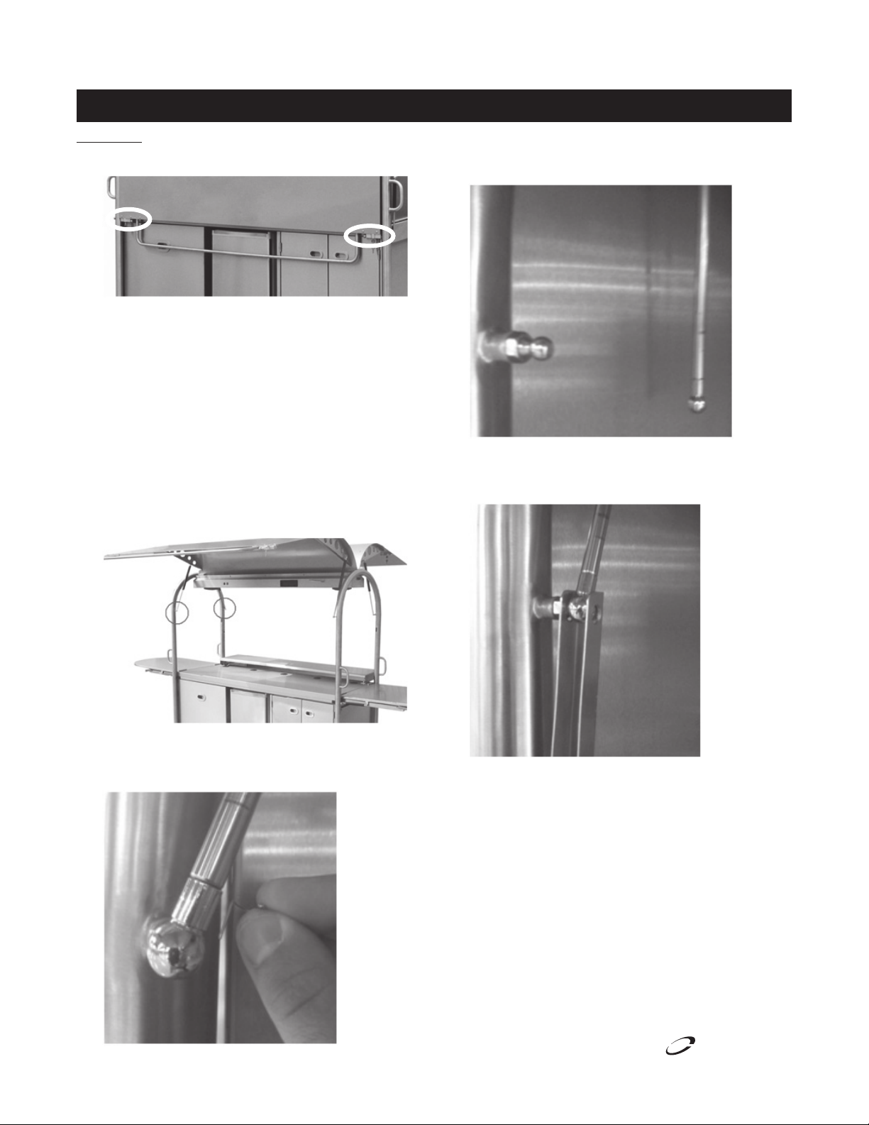
Safety Strut Locks Installation & Usage
Installation
1. Unlock gullwing locks and open lock slides.
2. Open operator side gullwing.
3. Unlock locks on the interior of customer side gullwing
and open lock slides.
4. Open customer side gullwing.
5. Have a second person hold the gullwings in the open
position while first person mounts the safety strut locks.
NOTE: During safety strut lock installation, the gullwings
will close if not supported!
6. Locate the points where the gullwing struts connect to
the vertical s/s tubing.
8. While second person holds gullwing, pull gently on the
strut to disconnect the bottom of it from strut mounting
ball.
9. Slide the end of the safety strut lock channel with the
holes over the bottom ball on strut and slide both back
onto strut mounting ball.
7. Locate small spring clip that holds the bottom end of the
strut to the vertical s/s tubing. Remove the clip by rotating it 180 degrees and pulling it up.
14
For customer service, call (800) 733-8829, (800) 733-8821, Fax (989) 773-3210, www.delfield.com
™
®
Page 15

Mobile Kiosks Installation, Use And Care Manual
Delfield
Safety Strut Locks Installation & Usage, continued
10. Push spring pin back into strut and rotate 180 degrees to
lock it into place.
Usage
1. Swing safety strut lock up onto strut. The top edge of the
channel should be under the bottom edge of the upper
larger diameter of the strut’s cylinder keeping it from
closing.
2. Repeat same steps on customer side gullwing. NOTE:
Only (1) safety strut lock is required per wing.
3. To close gullwings, simply swing safety strut locks back
down and let them hang in place.
™
®
For customer service, call (800) 733-8829, (800) 733-8821, Fax (989) 773-3210, www.delfield.com
15
Page 16
Mobile Kiosks Installation, Use And Care Manual
Delfield
Winterizing
Failure to perform the winterizing process will void the
warranties.
For Conditions Where Unit Is Stored Above 40°F
1. Drain fresh water tank.
2. Drain waste water tank and re-install.
3. Remove water filter and reinstall water filter container
without the water filter.
4. Cover unit with the provided black cover.
For Conditions Where Unit Is Stored Below 40°F
Option 1
1. Drain fresh water tank.
2. Drain waste water tank and re-install.
3. Remove water filter and reinstall water filter container
without the water filter.
4. Remove fresh water inlet from fresh water tank.
5. Insert fresh water inlet into RV antifreeze (NEVER USE
AUTOMOTIVE ANTIFREEZE) .
6. Turn on hot water at faucet to circulate RV antifreeze
(NEVER USE AUTOMOTIVE ANTIFREEZE) through hot
water system.
7. Turn off hot water at faucet.
8. Turn on cold water at faucet to circulate RV antifreeze
(NEVER USE AUTOMOTIVE ANTIFREEZE) through cold
water system.
9. Turn off cold water at faucet
10. Drain waste water tank and re-install.
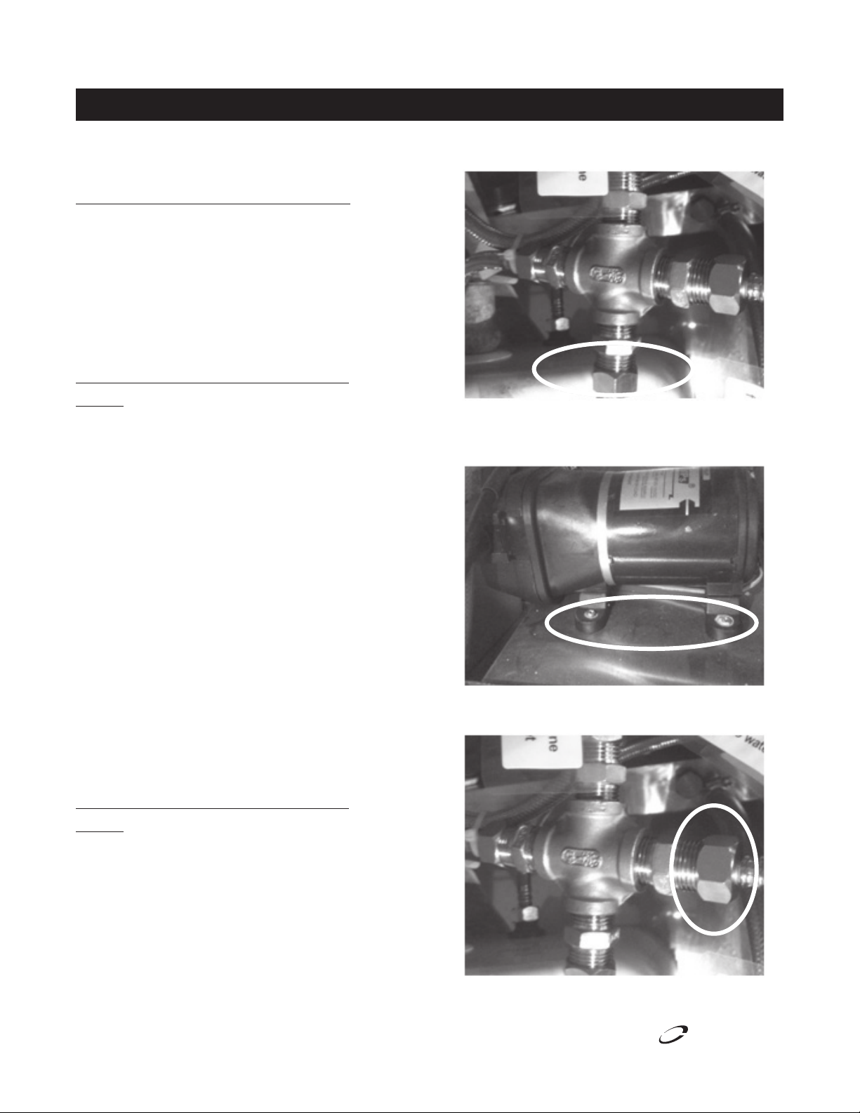
5. Disconnect discharge line from water pump at bottom of
cross joint fitting.
6. Unplug water pump, remove the (4) mounting bolts and
remove water pump from the mobile kiosk. Drain all
water from inside pump and supply and discharge lines.
7. Disconnect supply line from inline filter from right side of
cross joint fitting.
For Conditions Where Unit Is Stored Below 40°F
Option 2
1. Disconnect unit power
2. Open up sink compartment and lock in place and open up
end access door.
3. Remove hose from top of fresh water tank and then
remove and empty tank.
4. Disconnect the hose from top of waste water tank and
then remove and empty tank.
16
For customer service, call (800) 733-8829, (800) 733-8821, Fax (989) 773-3210, www.delfield.com
™
®
Page 17

Delfield
Winterizing, continued
Mobile Kiosks Installation, Use And Care Manual
8. Remove the (4) mounting screws that hold the inline filter
in place and remove it from the mobile kiosk unit. Open
cover, remove filter and drain filter and lines completely.
9. Insert new dry filter and screw cover back on filter and
remount in unit with same (4) screws
10. Disconnect (2) lines from top of water heater.
13. Disconnect both supply lines going to tap.
14. Open both faucet handles to drain any remaining water
from lines.
15. Dry off any residual water left in the mobile kiosk base.
16. Reconnect both supply lines to tap.
17. Replace water heater on hanger bracket and reconnect
lines.
18. Reconnect supply line to inline filter at right side of cross
joint fitting.
19. Remount water pump with (4) bolts and reconnect line to
bottom side of cross joint fitting.
20. Remount waste water tank and reconnect drain line from
sink.
21. Remount fresh water tank and reconnect supply line to
water pump.
11. Raise water heater up 1” off hanger bracket and remove
from the mobile kiosk.
12. Carefully turn upside down and drain completely of all
water.
™
®
For customer service, call (800) 733-8829, (800) 733-8821, Fax (989) 773-3210, www.delfield.com
Flushing The RV Antifreeze From Your Mobile Kiosk Water
System (After Winterizing)
1. Fill the fresh water tank.
2. Turn on hot water at faucet to circulate fresh water through
hot water system to purge all RV antifreeze.
3. Turn off hot water at faucet.
4. Turn on cold water at faucet to circulate fresh water
through cold water system to purge all RV antifreeze.
5. Turn off cold water at faucet.
6. Install a new water filter.
7. Drain waste water tank and re-install.
17
Page 18

Mobile Kiosks Installation, Use And Care Manual
Delfield
Maintenance
Door Gasket Maintenance
Door gaskets require regular cleaning to prevent mold and
mildew build up and also to retain the elasticity of the gasket.
Gasket cleaning can be done with the use of warm soapy water.
Avoid full strength cleaning products on gaskets as this can
cause them to become brittle and crack. Never use sharp tools
or knives to scrape or clean the gasket.
Caster Maintenance
Wipe casters with a damp cloth monthly to prevent corrosion.
The power switch must be turned to OFF and the
unit disconnected from the power source whenever
moving, replacing the lamp, performing service,
maintenance functions or cleaning.
Heated Display
Care must be taken to allow the Heated Display to cool down
before cleaning. The interior and exterior can be cleaned using
soap and warm water. If this isn’t sufficient, try ammonia
and water or a nonabrasive liquid cleaner. When cleaning
the exterior, always rub with the “grain” of the stainless steel
to avoid marring the finish. Do not use an abrasive cleaner
because it will scratch the stainless steel and can damage the
breaker strips and gaskets.
of stainless steel can be done with soap and water. Extreme
stains or grease should be cleaned with a non-abrasive cleaner
and plastic scrub pad. Always rub with the grain of the steel.
There are stainless steel cleaners available which can restore
and preserve the finish of the steels protective layer. Early signs
of stainless steel breakdown are small pits and cracks. If this
has begun, clean thoroughly and start to apply stainless steel
cleaners in attempt to restore the passivity of the steel.
Never use an acid based cleaning solution! Many
food products have an acidic content, which can
deteriorate the finish. Common items include,
tomatoes, peppers and other vegetables. Be sure
to clean the stainless steel surfaces under ALL food
products.
Doors/Hinges
Dry storage cupboard doors can be removed for easy cleaning.
Over time and with heavy use doors the hinges may become
loose. If this happens tighten the screws that mount the hinge
brackets to the frame of the unit. Loose or sagging doors can
cause the hinges to pull out of the frame, which may damage
both the doors and the hinges. In some cases this may require
qualified service agents or maintenance personnel to perform
repairs.
Stainless Steel Care and Cleaning
To prevent discoloration or rust on stainless steel several
important steps need to be taken. First, we need to understand
the properties of stainless steel. Stainless steel contains 7080% iron, which will rust. It also contains 12-30% chromium,
which forms an invisible passive film over the steel’s surface,
which acts as a shield against corrosion. As long as the
protective layer is intact, the metal is still stainless. If the film
is broken or contaminated, outside elements can begin to
breakdown the steel and begin to form discoloration or rust.
Proper cleaning of stainless steel requires soft cloths or plastic
scouring pads.
Never use a high pressure water wash for this
cleaning procedure as water can damage the
components.
NEVER USE STEEL PADS, WIRE BRUSHES OR
SCRAPERS!
Cleaning solutions need to be alkaline based or non-chloride
cleaners. Any cleaner containing chlorides will damage
the protective film of the stainless steel. Chlorides are also
commonly found in hard water, salts, and household and
industrial cleaners. If cleaners containing chlorides are used be
sure to rinse repeatedly and dry thoroughly. Routine cleaning
Racks
If necessary, remove the racks for cleaning. Use soft and wet
cloth and non irritating cleaning agent to clean the racks.
Do not place hot pans on/against the blue ABS liner.
Do not throw items into the storage area. Failure
to follow these recommendations could result in
damage to the interior of the cabinet. Overloading
the storage area, restricting the airflow, and
continuous opening and closing of the doors and
drawers will hamper the units ability to maintain
operational temperature.
Cleaning the Condenser Coil
In order to maintain proper refrigeration performance, the
condenser fins must be cleaned of dust, dirt and grease
regularly. It is recommended that this be done at least every
three months. If conditions are such that the condenser is totally
blocked in three months, the frequency of cleaning should be
increased. Clean the condenser with a vacuum cleaner or stiff
brush. If extremely dirty, a commercially available condenser
cleaner may be required.
Failure to maintain a clean condenser coil can initially cause high
temperatures and excessive run times. Continuous operation
with a dirty or clogged condenser coil can result in compressor
18
For customer service, call (800) 733-8829, (800) 733-8821, Fax (989) 773-3210, www.delfield.com
™
®
Page 19

Delfield
Maintenance, continued
Mobile Kiosks Installation, Use And Care Manual
failure. Neglecting the condenser coil cleaning procedures will
void any warranties associated with the compressor and cost
to replace the compressor.
Never use a high-pressure water wash for this cleaning
procedure as water can damage the electrical
components located near or at the condenser coil.
Waste Water Tank
It is recommended the waste water tank is removed and
thoroughly cleaned periodically based on the amount of use.
To drain the waste water tank, locate the hose and drain
valve. Direct the drain hose into the mains drain or secondary
container and turn on the valve to drain.
To remove the waste water tank for thorough cleaning, release
the stainless steel strap holding the water bottle and waste
water tank in position. Remove the water bottle.
Remove the waste water tank from inside of the unit. Using the
disconnect fitting (see below image), twist the fitting to remove
the main drain hose from the waste water tank. Your waste
water tank can be removed for cleaning. To access the main
vessel of the waste water tank, the top lid can be removed.
When reinstalling, please be sure to secure the main lid,
reconnect the main drain fitting, and slide back into position.
Place the water bottle in position and secure the stainless steel
strap.
Water Filter
The water filter is located on the right hand side of the service
module. The water filter cartridge will need regular replacement.
The frequency of replacement will depend on the use of a coffee
machine and/or other appliances. However, the maximum
interval should not exceed 6 months.
To change the cartridge in the water filter:
1. After turning off all appliances, drain residual water from
the filter.
2. Unscrew the filter from the mounting plate.
3. Unscrew the transparent filter cover.
4. Exchange old cartridge for new.
5. Replace securely when finished.
™
®
For customer service, call (800) 733-8829, (800) 733-8821, Fax (989) 773-3210, www.delfield.com
19
Page 20

Mobile Kiosks Installation, Use And Care Manual
Delfield
Trouble Shooting
The below chart is a guide to possible problems and causes. Please read through these and double check any problems you
may be having. The steps below will allow you to trouble shoot before placing a service call.
Problem Possible Causes Solution
Water is not hot Power not connected for sufficient time Allow 20 minutes to preheat
Water Heater is not turned on Locate power, and turn on
Water tank is empty Refill tank
Hot water unit faulty Unit can not run dry
Water does not come out of tap Power not connected Connect to power
Fresh water tank empty Refill
Pump faulty Call a qualified service technician
Inlet Pipe is Broken Call a qualified service technician
Water is not draining from sink Drain hose is blocked or kinked Remove obstruction
Waste water tank is full Empty waste water tank
Mobile kiosk is not level Level mobile kiosk
Refrigerator not cold Refrigerator not plugged in Plug in refrigerator, allow time to cool
Power not connected Connect to power
Circuit breaker on EMU tripped Reset breaker
Faulty refrigerator Call a qualified service technician
No water Water supply not connected Connect water supply
Inlet valve is open or not Open inlet valve
Water is blocked at any connection spot Call a qualified service technician
Drip from relief valve outlet Excessive water pressure Install pressure reducing valve at point of
connection with water inlet line
Water Pump Broken Call customer service
Can’t switch on the machine No power supply Locate power
Defective component(s) Call customer service
20
For customer service, call (800) 733-8829, (800) 733-8821, Fax (989) 773-3210, www.delfield.com
™
®
Page 21

Delfield
Replacement Parts
Mobile Kiosks Installation, Use And Care Manual
Dry Storage Module Replacement Parts
Part Number Description
GCP00060 Skirt
Mobile Kiosk Replacement Parts
Part Number Description
GCP00037 120V Water Heater
GCP00005 Cash Drawer
GCP00061 CD Player 2250
GCP00033 Down Lights
GCP00025 Feet
GCP00023 Filter
GCP00002 Gas Strut - Counter Extension
GCP00001 Gas Strut - Customer Service Shelf
GCP00003 Gas Strut
GCP00065 Key, Cash Drawer
GCP00064 Key, End Panel Locks
GCP00063 Key, Gullwing Locks
GCP00066 Key, Module Handle
GCP00022 Latch, Service Module (Male &
Female Set)
GCP00006 Lock - Counter Extension
GCP00011 Lock
GCP00049 Skirt
GCP00062 Speaker
GCP00034 Stereo Antenna
GCP00027 Switch (Round 12A)
GCP00026 Switch (Round 6A 250V)
GCP00008 Tap Set - Tap And Handles
GCP00007 Universal Castor - Lockable
GCP00045 Vinyl Cover 86.61”x32.87”x77.95”
GCP00038 Water Pump
Mini Replacement Parts
Part Number Description
GCP00024 Feet
GCP00009 Latch
GCP00043 Vinyl Cover
GCP00036 Water Pump
Sink Replacement Parts
Part Number Description
GCP00015 Retractable Spout
GCP00010 Round Stainless Steel Plug
GCP00042 Vinyl Cover
™
®
For customer service, call (800) 733-8829, (800) 733-8821, Fax (989) 773-3210, www.delfield.com
21
Page 22

Mobile Kiosks Installation, Use And Care Manual
Delfield
Standard Labor Guidelines To Repair Or Replace Parts On Delfield Equipment
Advice and recommendations given by Delfield Service Technicians do not constitute or guarantee any special coverage.
•Amaximumof1-hourisallowedtodiagnose a defective component.
•Amaximumof1-hourisallowedforretrieval of parts not in stock.
•Amaximumtravel distance of 100 miles round trip and 2-hours will be reimbursed.
•Overtime,installation/start-up,normalcontroladjustments,generalmaintenance,glassbreakage,freightdamage,and/or
correcting and end-user installation error will not be reimbursed under warranty unless pre-approved with a Service Work
Authorization from Delfield. You must submit the number with the service claim.
Labor Of 1-Hour Is Allowed To Replace:
•Thermostat•Contactor/Relay
•Evaporator/CondenserFanMotorandBlade• Hi-limit/ThermalProtectorSwitch
•SolenoidCoil•CirculatingFanMotorandBlade
•FanDelay/DefrostTerminationSwitch•Springs/Lowerator/Struts
•CompressorStartComponentsandOverloadProtector• DoorHinges,Locks,andGaskets
•DefrostTimer•Thermometer
Labor Of 2 Hours To Replace:
•DrawerTracks/Cartridges•DefrostElement
•PressureControl•HeatingElement
•SolenoidValve•Locate/RepairLeak
Labor Of 3 Hours To Replace:
•EPRorCPRValve•CondenserorEvaporatorCoil
•CapillaryTube
Labor Of 4 Hours To Replace:
•Compressor
This includes recovery of refrigerant and leak check.
$55.00 maximum reimbursement for refrigerant recovery (includes recovery machine, pump, torch, oil, flux, minor fittings,
solder, brazing rod, nitrogen, or similar fees.)
Refrigerants:
•R22Amaximumof$4.00/lb.or25¢/oz.willbereimbursed.
•R134AAmaximumof$5.00/lb.or31¢/oz.willbereimbursed.
•R404AAmaximumof$16.00/lb.or$1.00/oz.willbereimbursed.
22
For customer service, call (800) 733-8829, (800) 733-8821, Fax (989) 773-3210, www.delfield.com
™
®
Page 23

Mobile Kiosks Installation, Use And Care Manual
Delfield
Standard One Limited Year Warranty (One Year Parts And Labor.)
Delfield warrants to the Original Purchaser of the Delfield product
(herein called the “Unit”) that such Unit, and all parts thereof,
will be free from defects in material and workmanship under
normal use and service for a period of one (1) year from the
date of shipment of the Unit to the Original Purchaser or, if the
Original Purchaser returns the warranty card completely filled
out including the date of installation within thirty (30) days of
receipt of the Unit, one (1) year from the date of installation.
During this one year warranty period, Delfield will pay labor,
crating and freight incurred in the removal of the Unit or defective
component and shipment to Delfield. Reimbursement is subject
to the following limitations: A maximum of 1-hour is allowed
to diagnose a defective component; A maximum of 1-hour is
allowed for retrieval of parts not in stock; A maximum travel
distance of 100 miles round trip and 2-hours will be reimbursed.
Overtime, installation/start-up, normal control adjustments,
general maintenance, glass breakage, freight damage, and/or
correcting an end-user installation error will not be reimbursed
under warranty unless pre-approved with a Service Work
Authorization from Delfield. Delfield will pay the return costs if
the Unit or part thereof was defective.
The term “Original Purchaser” as used herein means that person,
firm, association, or corporation for whom the Unit was originally
installed.
This warranty does not apply to any Unit or part thereof that has
been subjected to misuse, neglect, alteration, or accident, such
as accidental damage to the exterior finish, operated contrary to
the recommendations specified by Delfield; or repaired or altered
by anyone other than Delfield in any way so as to, in Delfield’s
sole judgement, affect its quality or efficiency. This warranty
does not apply to any Unit that has been moved from the location
where it was originally installed. This warranty also does not
cover the refrigerator drier or the light bulbs used in the Unit.
The warranty is subject to the user’s normal maintenance and
care responsibility as set forth in the Service and Installation
Manual, such as cleaning the condenser coil, and is in lieu of
all other obligations of Delfield. Delfield neither assumes, nor
authorizes any other person to assume for Delfield, any other
liability in connection with Delfield’s products.
Removal or defacement of the original Serial Number or Model
Number from any Unit shall be deemed to release Delfield from
all obligations hereunder or any other obligations, express or
implied.
Parts furnished by suppliers to Delfield are guaranteed by Delfield
only to the extent of the original manufacturer’s express warranty
to Delfield. Failure of the Original Purchaser to receive such
manufacturers warranty shall in no way create any warranty,
expressed or implied, or any other obligation or liability on
Delfield’s part in respect thereof.
If shipment of a replacement part is requested prior to the arrival
in the Delfield factory of the part claimed to be defective, the
Original Purchaser must accept delivery of the replacement part
on a C.O.D. basis, with credit being issued after the part has
been received and inspected at Delfield’s plant and determined
by Delfield to be within this warranty.
Under no condition does this warranty give the Original Purchaser
the right to replace the defective Unit with a complete Unit of the
same manufacturer or of another make. Unless authorized by
Delfield in writing, this warranty does not permit the replacement
of any part, including the motor-compressor, to be made with the
part of another make or manufacturer.
No claims can be made under this warranty for spoilage of any
products for any reason, including system failure.
The installation contractor shall be responsible for building
access, entrance and field conditions to insure sufficient
clearance to allow any hood(s), vent(s), or Unit(s) if necessary,
to be brought into the building. Delfield will not be responsible
for structural changes or damages incurred during installation of
the Unit or any exhaust system.
Delfield shall not be liable in any manner for any default or delay
in performance hereunder caused by or resulting from any
contingency beyond Delfield’s control, including, but not limited
to, war, governmental restrictions or restraints, strike, lockouts,
injunctions, fire, flood, acts of nature, short or reduced supply of
raw materials, or discontinuance of the parts by the original part
manufacturer.
Except as provided in any Additional Four Year Protection
Plan, if applicable, and the Service Labor Contract, if
applicable, the foregoing is exclusive and in lieu of all other
warranties, whether written or oral, express or implied. This
warranty supersedes and excludes any prior oral or written
representations or warranties. Delfield expressly disclaims
any implied warranties of merchantability, fitness for a
particular purpose or compliance with any law, treaty, rule
or regulation relating to the discharge of substances into the
environment. The sole and exclusive remedies of any person
relating to the Unit, and the full liability of Delfield for any
breach of this warranty, will be as provided in this warranty.
Other than this Delfield Standard One Year Limited Warranty,
any applicable Delfield Additional Four Year Protection Plan or
applicable Delfield Service Labor Contract, the Original Purchaser
agrees and acknowledges that no other warranties are offered
or provided in connection with or for the Unit or any other part
thereof.
In no event will Delfield be liable for special, incidental or
consequential damages, or for damages in the nature of penalties.
™
®
For customer service, call (800) 733-8829, (800) 733-8821, Fax (989) 773-3210, www.delfield.com
23
Page 24

™
®
Delfield
Mt. Pleasant, MI Covington, TN
Thank you for choosing Delfield!
Help is a phone call away. Help our team of professional, courteous customer
service reps by having your model number and serial number available at the time
of your call (800) 733-8829.
Model: _______________________ S/N: ______________________
Installation Date: _______________
For a list of Delfield’s authorized parts depots,
visit our website at www.delfield.com.
™
®
Delfield
980S.IsabellaRd.,Mt.Pleasant,MI48858,U.S.A.•(989)773-7981or(800)733-8829•Fax(989)773-3210•www.deleld.com
Delfield reserves the right to make changes in design or specifications without prior notice. ©2011 The Delfield Company. All rights reserved. Printed in the U.S.A.
DMGCMK 11/11
 Loading...