

Page 1
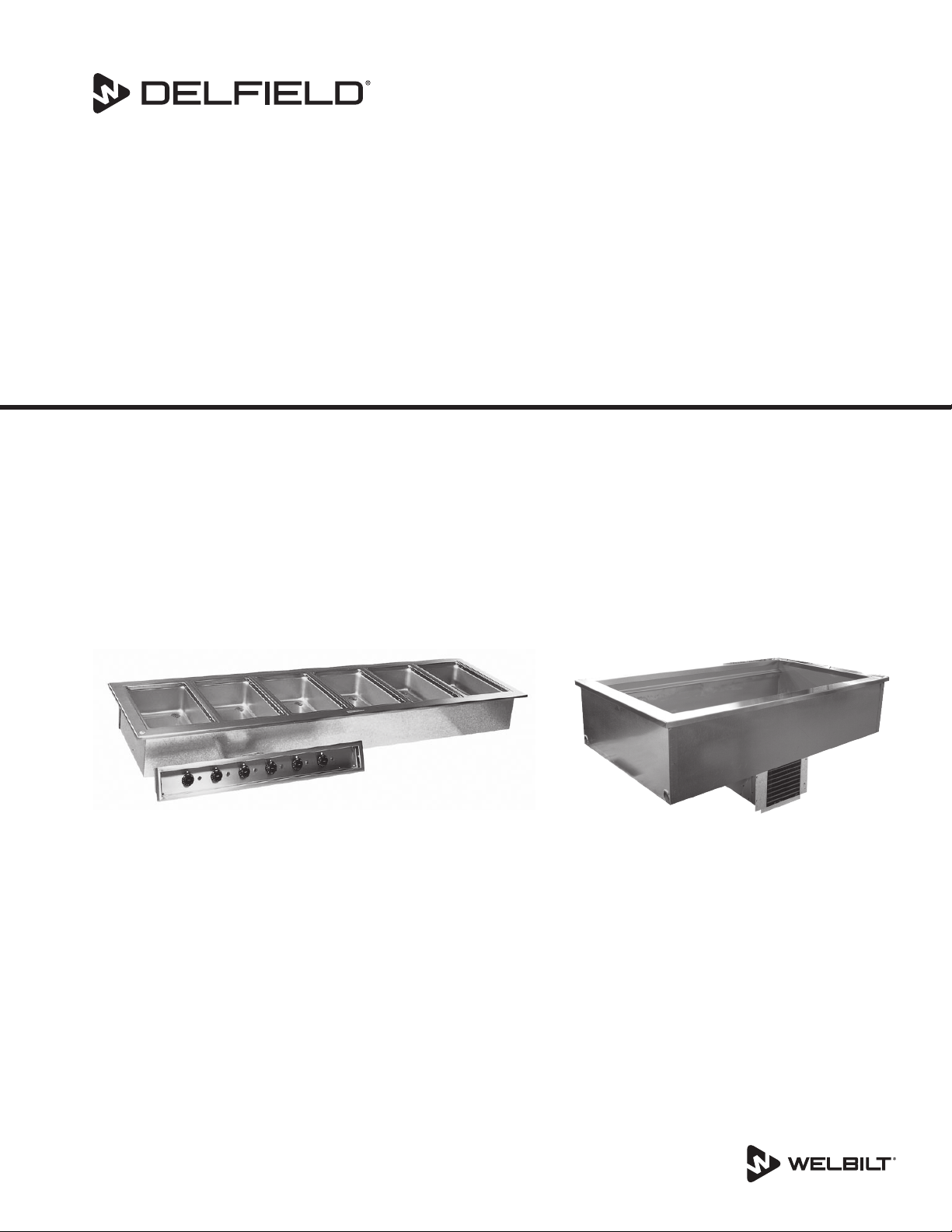
Drop Ins
Fresh Soluons, Fit For You
8100-EFP, N8000, N8000N, N8000-R, N8100BP,
N8100-BRP, N8100-FAP, N8200P, N8200GP, N8200STP, N8600P, N8700-D, N8700-DESP, N8700-R, N8800
Cold Pans & Hot Food Wells
Original Instructions
Installation, Operation and Maintenance Manual
This manual is updated as new information and models are released. Visit our website for the latest manual.
Original Document
Part Number 9291458C 07/22
Caution
,
Read this instruction before operating this equipment.
Page 2
Safety Notices
Warning
n
Read this manual thoroughly before operating, installing
or performing maintenance on the equipment. Failure
to follow instructions in this manual can cause property
damage, injury or death.
DANGER
Keep power cord AWAY from HEATED surfaces. DO NOT
immerse power cord or plug in water. DO NOT let power
cord hang over edge of table or counter.
DANGER
Do not lift the condensing unit by the refrigerant tubing
or other components. These features will not support
the condensing unit weight. Injury and unit damage
may occur!
DANGER
Do not install or operate equipment that has been
misused, abused, neglected, damaged, or altered/
modified from that of original manufactured
specifications.
Warning
n
This product contains chemicals known to the State
of California to cause cancer and/or birth defects or
other reproductive harm. Operation, installation, and
servicing of this product could expose you to airborne
particles of glasswool or ceramic fibers, crystalline
silica, and/or carbon monoxide. Inhalation of airborne
particles of glasswool or ceramic fibers is known to the
State of California to cause cancer. Inhalation of carbon
monoxide is known to the State of California to cause
birth defects or other reproductive harm.
Warning
n
Do not use electrical appliances inside the food storage
compartments of the appliance, unless they are of the
type recommended by the manufacturer.
Warning
n
Use caution when handling metal surface edges of all
equipment.
Warning
n
DO NOT touch refrigeration lines inside units; some may
exceed temperatures of 200°F (93.3°C).
DANGER
All utility connections and fixtures must be maintained
in accordance with Local and national codes.
Warning
n
This appliance is not intended for use by persons
(including children) with reduced physical, sensory
or mental capabilities, or lack of experience and
knowledge, unless they have been given supervision
concerning use of the appliance by a person responsible
for their safety. Do not allow children to play with this
appliance.
Warning
n
Do not store or use gasoline or other flammable vapors
or liquids inside or within the vicinity of this or any other
appliance. Never use flammable oil soaked cloths or
combustible cleaning solutions, for cleaning.
Warning
n
Authorized Service Representatives are obligated to
follow industry standard safety procedures, including,
but not limited to, local/national regulations for
disconnection / lock out / tag out procedures for all
utilities including electric, gas, water and steam.
Note
Proper installation, care and maintenance are
essential for maximum performance and trouble-free
operation of your equipment. Visit our website www.
wbtkitchencare.com for manual updates, translations,
or contact information for service agents in your area.
Notice
Climatic class 4 is defined as ambient conditions of 30°C
and 55% relative humidity, according to ISO 23953-2.
Note
These appliances are intended to be used for commercial
applications, for example in kitchens of restaurants,
canteens, hospitals and in commercial enterprises such
as bakeries, butcheries, etc., but not for continuous mass
production of food.
Notice
Climatic class 4 is defined as ambient conditions of 30°C
and 55% relative humidity, according to ISO 23953-2.
Note
These appliances are intended for commercial/industrial
use only. They are not intended for household use.
Page 3

Notice
This product utilizes Ecomate blowing agent methyl
formate
Page 4

Section 1
General Information
Section 2
Installation
Section 3
Operation
Table of Contents
Model Numbers .................................................................................................................. 5
Serial Number Location ..................................................................................................... 6
Warranty Information ........................................................................................................ 6
Regulatory Certifications ..................................................................................................6
Domestic Models ....................................................................................................................................6
Export Models .........................................................................................................................................6
Location ..............................................................................................................................8
Weight Of Equipment ........................................................................................................8
Dimensions ....................................................................................................................... 10
Clearance Requirements ..................................................................................................12
Cutout Installation Dimensions ......................................................................................13
Curved Drop-In Cutout Details ....................................................................................................... 16
Drop-In Counter Installation ...........................................................................................17
Ice Cooled Drop-In Units .................................................................................................................. 17
8100P Series Self-Contained Refrigerated Drop-In Units ..................................................... 18
8100P Series Forced-Air Refrigerated Drop-In Units .............................................................. 22
8200P Series Self-Contained Refrigerated Drop-In Units..................................................... 24
8600P Self-Contained Combo Hot/Cold Drop-In Units ......................................................... 26
8700 Hot Food Well Drop-In Units ................................................................................................ 28
Electrical Service ..............................................................................................................29
Voltage .................................................................................................................................................... 29
Ground Fault Circuit Interrupter .................................................................................................... 29
Rated Amperages, Horsepower, Voltage & Power Cord Chart ............................................ 29
Refrigeration ....................................................................................................................31
Optional Auto Fill Installation .........................................................................................32
Applicable to N8600 & N8800 Models ......................................................................................... 32
Applicable to N8700 Models ........................................................................................................... 32
Product Quality in Cold Pans ...........................................................................................34
8100-EF(N)P Series Operation .........................................................................................35
Temperature Control & Display ...................................................................................................... 35
Changing Display from Fahrenheit to Celsius on ERC112 Control .................................... 36
N8100BP, N8100-BRP & N8100NBP Operation ..............................................................37
N8100-FAP Operation ......................................................................................................38
N8200P & N8200-STP Operation .....................................................................................38
Operation N8200GP .........................................................................................................38
8600P Hot/Cold Series Operation ...................................................................................39
N8700-D, N8700N, N8700-R & N8800 Series Operation ...............................................40
N8700-DESP Operation....................................................................................................41
4 Part Number: 9291458A 07/22
Page 5

Section 4
Maintenance
Table of Contents (continued)
Cleaning and Sanitizing Procedures ...............................................................................42
General .................................................................................................................................................... 42
Exterior Cleaning ................................................................................................................................. 43
Cleaning the Condenser Coil .......................................................................................................... 43
N8100-FA Series Drain Maintenance ............................................................................................ 43
Part Number: 9291458A 07/22 5
Page 6
Section 1
General Information
Model Numbers
8100-EFP Series
LiquiTec® Eutetic Fluid Refrigerated Cold Pans - R290
8118-EFP 8132-EFP 8145-EFP
8159-EFP 8172-EFP 8186-EFP
8100-EF-E Export Series
LiquiTec® Eutetic Fluid Refrigerated Cold Pans - R404A
8118-EF-E 8132-EF-E 8145-EF-E
8159-EF-E 8172-EF-E 8186-EF-E
8100-EFNP Series
LiquiTec® Slim Line Eutetic Fluid Refrigerated Cold Pans -
R290
8148-EFNP 8169-EFNP 8191-EFNP
8100-EFN-E Export Series
LiquiTec® Slim Line Eutetic Fluid Refrigerated Cold Pans -
R404A
8148-EFN-E 8169-EFN-E 8191-EFN-E
N8000 Series
Ice Cooled Cold Pans
N8018 N8030 N8043
N8056 N8069 N8081
N8000N Series
Narrow Ice Cooled Cold Pans
N8046N N8068N
N8000-R Series
Curved Ice Cooled Cold Pans
N8044-R N8059-R N8076-R
N8094-R
N8100BP Series
Self-Contained Mechanically Cooled Pans - R290
N8118BP N8130BP N8143BP
N8156BP N8169BP N8181BP
N8100B-E Export Series
Self-Contained Mechanically Cooled Pans - R404A
N8118B-E N8130B-E N8143B-E
N8100B-E Export Series
Self-Contained Mechanically Cooled Pans - R134A
N8156B-E N8169B-E
N8100BRP Series
Curved Self-Contained Mechanically Cooled Pans - R290
N8144-BRP N8159-BRP N8176-BRP
N8194-BRP
N8100-FAP Series
Forced Air Drop-In Mechanically Cooled Cold Pans - R290
N8131-FAP N8144-FAP N8157-FAP
N8169-FAP N8182-FAP
N8100NBP Series
Self-Contained Mechanically Cooled Pans Narrow Style -
R290
N8146NBP N8168NBP
N8100NB-E Export Series
Self-Contained Mechanically Cooled Pans Narrow Style -
R404A
N8146NB-E N8168NB-E
N8200P Series
Self-Contained Frost Tops - R290
N8231P N8245P N8259P
N8273P N8287P
N8200-E Export Series
Self-Contained Frost Tops - R404A
N8231-E N8245-E N8259-E
N8273-E N8287-E
N8200GP Series
Self-Contained Granite Cold Slabs - R290
N8231GP N8245GP N8259GP
N8273GP
N8200G-E Export Series
Self-Contained Granite Cold Slabs - R404A
N8231G-E N8245G-E N8259G-E
N8200-STP Series
Self-Contained Frost Tops - R290
N8230-STP N8240-STP N8256-STP
N8258-STP N8275-STP
N8600P Series
Self Contained Combination Hot/Cold Food Wells - R290
N8630P N8643P N8656P
N8669P N8681P
N8700D Series
Individually Controlled Heated Food Wells
N8717-D N8731-D N8745-D
N8759-D N8773-D N8787-D
N8700D-E Export Series
Individually Controlled Heated Food Wells
N8717-D-E N8731-D-E N8745-D-E
N8759-D-E N8773-D-E N8787-D-E
N8700DESP Series
Individually Controlled Energy Savings Heated Food Wells
N8717-DESP N8731-DESP N8745-DESP
N8759-DESP N8773-DESP N8787-DESP
N8700-D-ESP-E Export Series
Individually Controlled Energy Savings Heated Food Wells
N8717-D-ESP-E N8731-D-ESP-E N8745-D-ESP-E
N8759-D-ESP-E N8773-D-ESP-E N8787-D-ESP-E
N8700N Series
Individually Controlled Heated Narrow Food Wells
N8746ND N8768N N8768ND
N8700-R Series
Curved Individually Controlled Heated Food Wells
N8744-R N8759-R N8776-R
N8794-R
N8800 Series
Single Tank Electric Hot Food Wells
N8831 N8845 N8859
N8873 N8887
N8800-E Export Series
Single Tank Electric Hot Food Wells
N8831-E N8845-E N8859-E
N8873-E N8887-E
† Drop-In FlexiWell & FlexiTop Models N8600-FWP and
N8200-FTP are within the FlexiWell manual 9291544
6 Part Number: 9291458C 07/22
Page 7
Section 1 General Information
Serial Number Location
Ther serial number is listed on the serial tag. If applicable it
will also list the refrigerant used and the amount of charge.
• The serial tag on self-contained refrigerated units is
located near the condensing unit.
• The serial tag on ice cooled units and remote
refrigerated units is on the outside bottom of the food
well.
• On hot food pans and hot/cold combination pans, the
serial tag is located on the back of the control raceway
or remote panel.
Always have the serial number of your unit available
when calling for parts or service.
Warranty Information
• Register your product for warranty,
• Verify warranty information,
• View and download a copy of your warranty,
at www.delfield.com/warranty
Service
Regulatory Certifications
DOMESTIC MODELS
All domestic models are certified by:
•
All domestic electrical models are certified by:
•
•
EXPORT MODELS
230-240Volt, 50Hertz, 1Phase models are certified by:
•
• Technical Inspection Association
• European Conformity
National Sanitation Foundation (NSF)
Underwriters Laboratories (UL)
Underwriters Laboratories of Canada (cUL)
National Sanitation Foundation (NSF)
For parts and service consult Welbilt KitchenCare
at 1-844-724-CARE
Part Number: 9291458C 07/22 7
Page 8
Section 2
Installation
DANGER
Installation must comply with all applicable fire and
health codes in your jurisdiction.
DANGER
Use appropriate safety equipment during installation
and servicing.
Warning
n
Remove all removable panels before lifting and
installing.
Warning
n
If a refrigerated base does not have a condensate
evaporator supplied, you must connect the condensate
line to a suitable drain. Otherwise, water will collect on
the floor, causing a potentially hazardous situation.
Warning
n
Moisture collecting from improper drainage can create a
slippery surface on the floor and a hazard to employees.
It is the owner’s responsibility to provide a container or
outlet for drainage.
Warning
n
This equipment is intended for indoor use only. Do not
install or operate this equipment in outdoor areas.
Caution
,
The units with LiquiTec technology cold pans contain a
non-toxic eutectic fluid within a sealed inner liner. This
fluid may leak if the tank is punctured so care must be
taken when uncrating and setting in place. The eutectic
fluid is non-toxic and may be flushed down a disposal
drain. Units with a Eutectic Fluid Cold Pan require the
same precautions. The fluid is NOT refillable and loss of
fluid due to a puncture would cause irreparable damage.
If the LiquiTec unit cold pans leak, immediately call the
Delfield service department directly at 1-800-733-8821
not your local service agent.
Caution
,
Do not position the air intake vent near steam or heat
exhaust of another appliance.
Note
This symbol indicates the location of the equipotential
bonding conductor connection.
Warning
n
Do not damage the refrigeration circuit when installing,
maintaining or servicing the unit.
Warning
n
This equipment must be positioned so that the plug is
accessible unless other means for disconnection from
the power supply (e.g., circuit breaker or disconnect
switch) is provided.
Warning
n
Adequate means must be provided to limit the
movement of this appliance without depending on or
transmitting stress to the electrical conduit.
Warning
n
To avoid instability the installation area must be capable
of supporting the combined weight of the equipment
and product. Additionally the equipment must be level
side to side and front to back.
Note
This symbol indicates a hot surface that can cause injury
to persons..
8 Part Number: 9291458C 07/22
Page 9
Section 2 Installation
Location
The location selected for the equipment must meet the
following criteria. If any of these criteria are not met, select
another location.
• Units are intended for indoor use only.
• The location MUST be level, stable and capable of
supporting the weight of the equipment.
• The location MUST be free from and clear of
combustible materials.
• Equipment MUST be level both front to back and side to
side.
• Position the equipment so it will not tip or slide.
• Recommended air temperature is 41° - 86°F (5° - 30°C).
• Proper air supply for ventilation is REQUIRED AND
CRITICAL for safe and efficient operation. Refer to
Clearance Requirements chart on page 13.
• Do not obstruct the flow of ventilation air. Make sure the
air vents of the equipment are not blocked.
• Do not install the equipment directly over a drain.
Steam rising up out of the drain will adversely affect
operation, air circulation, and damage electrical /
electronic components.
Weight Of Equipment
Model Ship Weight
8100-EFP Series
8118-EFP 169lbs (77kg)
8132-EFP 215lbs (98kg)
8145-EFP 265lbs (120kg)
8159-EFP 285lbs (130kg)
8172-EFP 295lbs (134kg)
8186-EFP 394lbs (179kg)
8100-EF-E Export Series
8118-EF-E 169lbs (77kg)
8132-EF-E 215lbs (98kg)
8145-EF-E 265lbs (120kg)
8159-EF-E 285lbs (130kg)
8172-EF-E 295lbs (134kg)
8186-EF-E 394lbs (179kg)
8100-EFNP Series
8148-EFNP 235lbs (107kg)
8169-EFNP 285lbs (130kg)
8191-EFNP 295lbs (134kg)
8100-EFN-E Export Series
8148-EFN-E 235lbs (107kg)
8169-EFN-E 285lbs (130kg)
8191-EFN-E 295lbs (134kg)
N8000 Series
N8018
N8030
N8043
N8056
N8069
N8081
N8000N Series
N8046N 100lbs (45kg)
N8068N 120lbs (55kg)
N8000-R Series
N8044-R 100lbs (45kg)
N8059-R 118lbs (53kg)
N8076-R 145lbs (65kg)
N8094-R 164lbs (74kg)
N8100BP Series
N8118BP 100lbs (45kg)
N8130BP 140lbs (64kg)
N8143BP 173lbs (78kg)
N8156BP 205lbs (93kg)
N8169BP 225lbs (102kg)
N8181BP 258lbs (117kg)
N8100B-E Export Series - R404A
N8118B-E 100lbs (45kg)
N8130B-E 140lbs (64kg)
N8143B-E 173lbs (78kg)
N8100B-E Export Series - R134A
N8156B-E 205lbs (93kg)
N8169B-E 225lbs (102kg)
N8100BRP Series
N8144-BRP 161lbs (72kg)
N8159-BRP 184lbs (83kg)
N8176-BRP 233lbs (105kg)
N8194-BRP 243lbs (109kg)
38lbs (17kg)
84lbs (38kg)
110lbs (50kg)
139lbs (63kg)
160lbs (73kg)
197lbs (89kg)
Part Number: 9291458C 07/22 9
Page 10
Installation Section 2
Model Ship Weight
N8100-FAP Series
N8131-FAP 168lbs (76kg)
N8144-FAP 175lbs (79kg)
N8157-FAP 225lbs (102kg)
N8169-FAP 235lbs (107kg)
N8182-FAP 406lbs (184kg)
N8100NBP Series
N8146NBP 175lbs (80kg)
N8168NBP 240lbs (109kg)
N8100NB-E Export Series
N8146NB-E 175lbs (80kg)
N8168NB-E 240lbs (109kg)
N8200P Series
N8231P 142lbs (64kg)
N8245P 168lbs (76kg)
N8259P 193lbs (88kg)
N8273P 209lbs (95kg)
N8287P 239lbs (108kg)
N8200-E Export Series
N8231-E 142lbs (64kg)
N8245-E 168lbs (76kg)
N8259-E 193lbs (88kg)
N8273-E 209lbs (95kg)
N8287-E 239lbs (108kg)
N8200GP Series
N8231GP 219lbs (99kg)
N8245GP 284lbs (129kg)
N8259GP 338lbs (153kg)
N8273GP 425lbs (193kg)
N8200G-E Export Series
N8231G-E 219lbs (99kg)
N8245G-E 284lbs (129kg)
N8259G-E 338lbs (153kg)
N8200-STP Series
N8230-STP 142lbs (64kg)
N8240-STP 168lbs (76kg)
N8256-STP 193lbs (88kg)
N8258-STP 209lbs (95kg)
N8275-STP 239lbs (108kg)
N8600P Series
N8630P 164lbs (74kg)
N8643P 198lbs (90kg)
N8656P 233lbs (106kg)
N8669P 266lbs (121kg)
N8681P 301lbs (137kg)
N8700D Series
N8717-D 41lbs (19kg)
N8731-D 99lbs (45kg)
N8745-D 134lbs (61kg)
N8759-D 166lbs (75kg)
N8773-D 186lbs (84kg)
N8787-D 236lbs (107kg)
N8700D-E Export Series
N8717-D-E 41lbs (19kg)
N8731-D-E 99lbs (45kg)
N8745-D-E 134lbs (61kg)
N8759-D-E 166lbs (75kg)
N8773-D-E 186lbs (84kg)
N8787-D-E 236lbs (107kg)
Model Ship Weight
N8700DESP Series
N8717-DESP 41lbs (19kg)
N8731-DESP 99lbs (45kg)
N8745-DESP 134lbs (61kg)
N8759-DESP 166lbs (75kg)
N8773-DESP 186lbs (84kg)
N8787-DESP 236lbs (107kg)
N8700-D-ESP-E Export Series
N8717-D-ESP-E 41lbs (19kg)
N8731-D-ESP-E 99lbs (45kg)
N8745-D-ESP-E 134lbs (61kg)
N8759-D-ESP-E 166lbs (75kg)
N8773-D-ESP-E 186lbs (84kg)
N8787-D-ESP-E 236lbs (107kg)
N8700N Series
N8746ND 100lbs (45kg)
N8768N 130lbs (59kg)
N8768ND 130lbs (59kg)
N8700-R Series
N8744-R 99lbs (45kg)
N8759-R 134lbs (61kg)
N8776-R 166lbs (75kg)
N8794-R 186lbs (84kg)
N8800 Series
N8831 100lbs (45kg)
N8845 136lbs (62kg)
N8859 158lbs (72kg)
N8873 195lbs (88kg)
N8887 224lbs (102kg)
N8800-E Export Series
N8831-E 100lbs (45kg)
N8845-E 136lbs (62kg)
N8859-E 158lbs (72kg)
N8873-E 195lbs (88kg)
N8887-E 224lbs (102kg)
† Drop-In FlexiWell & FlexiTop Models N8600-FWP and
N8200-FTP are within the FlexiWell manual 9291544
10 Part Number: 9291458C 07/22
Page 11
Section 2 Installation
Dimensions
Model Length Depth Height 12x20
8100-EFP Series
8118-EFP 18.20”
(46cm)
8132-EFP 31.76”
(81cm)
8145-EFP 45.32”
(115cm)
8159-EFP 58.88”
(150cm)
8172-EFP 72.44”
(184cm)
8186-EFP 86”
(218cm)
8100-EF-E Export Series
8118-EF-E 18.20”
(46cm)
8132-EF-E 31.76”
(81cm)
8145-EF-E 45.32”
(115cm)
8159-EF-E 58.88”
(150cm)
8172-EF-E 72.44”
(184cm)
8186-EF-E 86”
(218cm)
8100-EFNP Series
8148-EFNP 47.66”
(121cm)
8169-EFNP 69.22”
(176cm)
8191-EFNP 90.78”
(231cm)
8100-EFN-E Export Series
8148-EFN-E 47.66”
(121cm)
8169-EFN-E 69.22”
(176cm)
8191-EFN-E 90.78”
(231cm)
N8000 Series
N8018 18“
(46cm)
N8030 30.75“
(78cm)
N8043 43.5“
(110cm)
N8056 56.25“
(143cm)
N8069 69“
(175cm)
N8081 81.75“
(208cm)
26”
(66cm)
26”
(66cm)
26”
(66cm)
26”
(66cm)
26”
(66cm)
26”
(66cm)
26”
(66cm)
26”
(66cm)
26”
(66cm)
26”
(66cm)
26”
(66cm)
26”
(66cm)
18”
(46cm)
18”
(46cm)
18”
(46cm)
18”
(46cm)
18”
(46cm)
18”
(46cm)
26”
(66cm)
26”
(66cm)
26”
(66cm)
26”
(66cm)
26”
(66cm)
26”
(66cm)
23.25”
(59cm)
23.25”
(59cm)
23.25”
(59cm)
23.25”
(59cm)
23.25”
(59cm)
23.25”
(59cm)
23.25”
(59cm)
23.25”
(59cm)
23.25”
(59cm)
23.25”
(59cm)
23.25”
(59cm)
23.25”
(59cm)
23.25”
(59cm)
23.25”
(59cm)
23.25”
(59cm)
23.25”
(59cm)
23.25”
(59cm)
23.25”
(59cm)
10.75”
(27cm)
10.75”
(27cm)
10.75”
(27cm)
10.75”
(27cm)
10.75”
(27cm)
10.75”
(27cm)
Pans
1
2
3
4
5
6
1
2
3
4
5
6
2
3
4
2
3
4
1
2
3
4
5
6
Model Length Depth Height 12x20
Pans
N8000N Series
N8046N 46.75“
(119cm)
N8068N 67.5“
(171cm)
N8000-R Series
N8044-R 40.48”
(103cm)
N8059-R 57.22”
(145cm)
N8076-R 73.68”
(187cm)
N8094-R 89.89”
(228cm)
N8100B Series
N8118B 18”
(46cm)
N8130B 30.75”
(78cm)
N8143B 43.5”
(110cm)
N8156B 56.25”
(143cm)
N8169B 69”
(175cm)
N8181B 81.75”
(208cm)
N8100B-E Export Series - R404A
N8118B-E 18”
(46cm)
N8130B-E 30.75”
(78cm)
N8143B-E 43.5”
(110cm)
N8100B-E Export Series - R134A
N8156B-E 56.25”
(143cm)
N8169B-E 69”
(175cm)
N8100BRP Series
N8144-BRP 40.43”
(103cm)
N8159-BRP 57.22”
(145cm)
N8176-BRP 73.68”
(187cm)
N8194-BRP 89.86”
(228cm)
N8100-FAP Series
N8131-FAP 31.25”
(79cm)
N8144-FAP 44”
(112cm)
N8157-FAP 56.75”
(144cm)
N8169-FAP 69.5”
(177cm)
N8182-FAP 82.25”
(209cm)
18“
(46cm)
18“
(46cm)
26.05”
(66cm)
26.05”
(66cm)
26.05”
(66cm)
26.05”
(66cm)
26”
(66cm)
26”
(66cm)
26”
(66cm)
26”
(66cm)
26”
(66cm)
26”
(66cm)
26”
(66cm)
26”
(66cm)
26”
(66cm)
26”
(66cm)
26”
(66cm)
26.05”
(66cm)
26.05”
(66cm)
26.05”
(66cm)
26.05”
(66cm)
26.67”
(68cm)
26.67”
(68cm)
26.67”
(68cm)
26.67”
(68cm)
26.67”
(68cm)
10.75“
(27cm)
10.75“
(27cm)
10.77”
(27cm)
10.77”
(27cm)
10.77”
(27cm)
10.77”
(27cm)
21.87”
(56cm)
21.87”
(56cm)
21.87”
(56cm)
21.87”
(56cm)
21.87”
(56cm)
21.87”
(56cm)
21.87”
(56cm)
21.87”
(56cm)
21.87”
(56cm)
21.87”
(56cm)
21.87”
(56cm)
21.81”
(55cm)
21.81”
(55cm)
21.81”
(55cm)
21.81”
(55cm)
26.62”
(68cm)
26.62”
(68cm)
26.62”
(68cm)
28.62”
(73cm)
28.62”
(73cm)
2
3
2
3
4
5
1
2
3
4
5
6
1
2
3
4
5
2
3
4
5
2
3
4
5
6
Part Number: 9291458C 07/22 11
Page 12
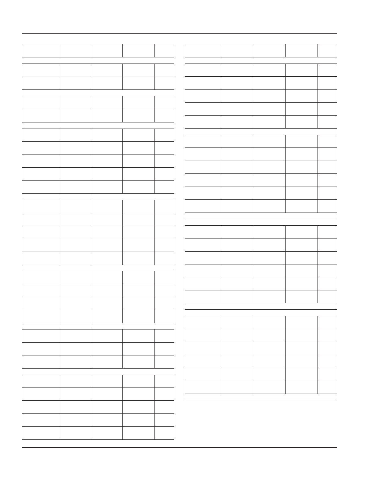
Installation Section 2
Model Length Depth Height 12x20
N8100NBP Series
N8146NBP 46.75”
(119cm)
N8168NBP 67.5”
(171cm)
N8100NB-E Export Series
N8146NB-E 46.75”
(119cm)
N8168NB-E 67.5”
(171cm)
N8200P Series
N8231P 31.75"
(81cm)
N8245P 45.63”
(116cm)
N8259P 59.5”
(151cm)
N8273P 73.38"
(186cm)
N8287P 87.25”
(222cm)
N8200-E Export Series
N8231-E 31.75"
(81cm)
N8245-E 45.63”
(116cm)
N8259-E 59.5”
(151cm)
N8273-E 73.38"
(186cm)
N8287-E 87.25”
(222cm)
N8200GP Series
N8231GP 31.75”
(81cm)
N8245GP 45.63”
(116cm)
N8259GP 59.5”
(151cm)
N8273GP 73.38”
(186cm)
N8200G-E Export Series
N8231G-E 31.75”
(81cm)
N8245G-E 45.63”
(116cm)
N8259G-E 59.5”
(151cm)
N8200-STP Series
N8230-STP 29.60"
(75cm)
N8240-STP 39.70”
(101cm)
N8256-STP 55.60”
(141cm)
N8258-STP 57.60"
(146cm)
N8275-STP 75.50"
(192cm)
18”
(46cm)
18”
(46cm)
18”
(46cm)
18”
(46cm)
26”
(66cm)
26”
(66cm)
26”
(66cm)
26”
(66cm)
26”
(66cm)
26”
(66cm)
26”
(66cm)
26”
(66cm)
26”
(66cm)
26”
(66cm)
25.87”
(66cm)
25.87”
(66cm)
25.87”
(66cm)
25.87”
(66cm)
25.87”
(66cm)
25.87”
(66cm)
25.87”
(66cm)
22”
(56cm)
29.60”
(75cm)
22”
(56cm)
29.60”
(75cm)
29.60”
(75cm)
21.81”
(55cm)
21.81”
(55cm)
21.81”
(55cm)
21.81”
(55cm)
15.75”
(40cm)
15.75”
(40cm)
15.75”
(40cm)
15.75”
(40cm)
15.75”
(40cm)
15.75”
(40cm)
15.75”
(40cm)
15.75”
(40cm)
15.75”
(40cm)
15.75”
(40cm)
19”
(48cm)
19”
(48cm)
19”
(48cm)
19”
(48cm)
19”
(48cm)
19”
(48cm)
19”
(48cm)
15.70”
(40cm)
15.70”
(40cm)
15.70”
(40cm)
15.70”
(40cm)
15.70”
(40cm)
Pans
2
3
2
3
NA
NA
NA
NA
NA
NA
NA
NA
NA
NA
NA
NA
NA
NA
NA
NA
NA
NA
NA
NA
NA
NA
Model Length Depth Height 12x20
N8600P Series
N8630P 30.75”
(78cm)
N8643P 43.5”
(110cm)
N8656P 56.25”
(143cm)
N8669P 69”
(175cm)
N8681P 81.75”
(208cm)
N8700D Series
N8717-D 17.88”
(45cm)
N8731-D 31.75”
(81cm)
N8745-D 45.63”
(116cm)
N8759-D 59.5”
(151cm)
N8773-D 73.38”
(186cm)
N8787-D 87.25”
(222cm)
*14” Overall height including drain connection
N8700D-E Export Series
N8717-D-E 17.88”
(45cm)
N8731-D-E 31.75”
(81cm)
N8745-D-E 45.63”
(116cm)
N8759-D-E 59.5”
(151cm)
N8773-D-E 73.38”
(186cm)
N8787-D-E 87.25”
(222cm)
*14” Overall height including drain connection
N8700DESP Series
N8717-DESP 17.89”
(45cm)
N8731-DESP 31.76”
(81cm)
N8745-DESP 45.63”
(116cm)
N8759-DESP 59.50”
(151cm)
N8773-DESP 73.37”
(186cm)
N8787-DESP 87.24”
(222cm)
*14” Overall height including drain connection
26”
(66cm)
26”
(66cm)
26”
(66cm)
26”
(66cm)
26”
(66cm)
26”
(66cm)
26”
(66cm)
26”
(66cm)
26”
(66cm)
26”
(66cm)
26”
(66cm)
26”
(66cm)
26”
(66cm)
26”
(66cm)
26”
(66cm)
26”
(66cm)
26”
(66cm)
26”
(66cm)
26”
(66cm)
26”
(66cm)
26”
(66cm)
26”
(66cm)
26”
(66cm)
23.75”
(60cm)
23.75”
(60cm)
23.75”
(60cm)
23.75”
(60cm)
23.75”
(60cm)
9.5”
(24cm)*
9.5”
(24cm)*
9.5”
(24cm)*
9.5”
(24cm)*
9.5”
(24cm)*
9.5”
(24cm)*
9.5”
(24cm)*
9.5”
(24cm)*
9.5”
(24cm)*
9.5”
(24cm)*
9.5”
(24cm)*
9.5”
(24cm)*
9.5”
(24cm)*
9.5”
(24cm)*
9.5”
(24cm)*
9.5”
(24cm)*
9.5”
(24cm)*
9.5”
(24cm)*
Pans
2
3
4
5
6
1
2
3
4
5
6
1
2
3
4
5
6
1
2
3
4
5
6
12 Part Number: 9291458C 07/22
Page 13
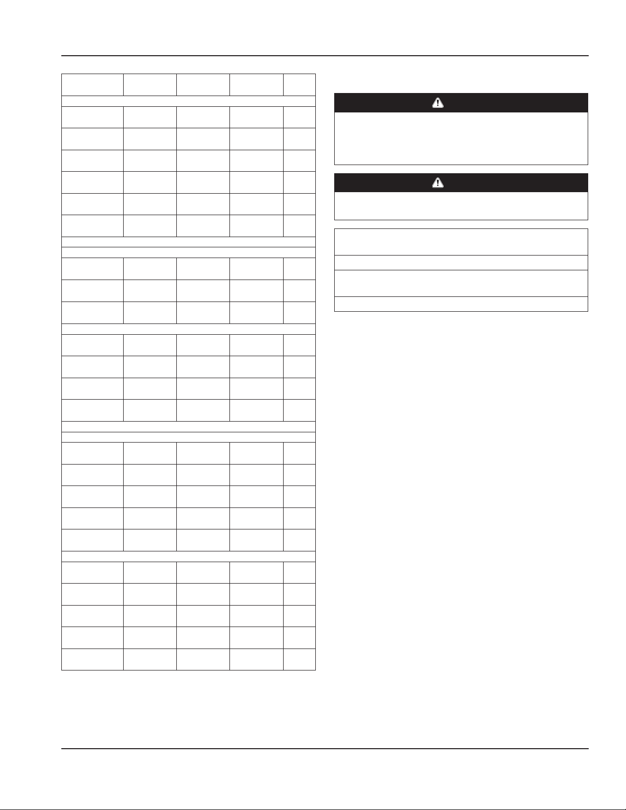
Section 2 Installation
Model Length Depth Height 12x20
N8700-D-ESP-E Export Series
N8717-D-ESP-E 17.89”
(45cm)
N8731-D-ESP-E 31.76”
(81cm)
N8745-D-ESP-E 45.63”
(116cm)
N8759-D-ESP-E 59.50”
(151cm)
N8773-D-ESP-E 73.37”
(186cm)
N8787-D-ESP-E 87.24”
(222cm)
*14” Overall height including drain connection
N8700N Series
N8746ND 45.61”
(116cm)
N8768N 67.48”
(172cm)
N8768ND 67.48”
(172cm)
N8700-R Series
N8744-R 40.48”
(103cm)
N8759-R 57.22”
(145cm)
N8776-R 73.68”
(187cm)
N8794-R 89.80”
(228cm)
*14” Overall height including drain connection
N8800 Series
N8831 31.75”
(81cm)
N8845 45.63”
(116cm)
N8859 59.5”
(151cm)
N8873 73.38”
(186cm)
N8887 87.25”
(222cm)
N8800-E Export Series
N8831-E 31.75”
(81cm)
N8845-E 45.63”
(116cm)
N8859-E 59.5”
(151cm)
N8873-E 73.38”
(186cm)
N8887-E 87.25”
(222cm)
26”
(66cm)
26”
(66cm)
26”
(66cm)
26”
(66cm)
26”
(66cm)
26”
(66cm)
15.87”
(40cm)
15.87”
(40cm)
15.87”
(40cm)
26.05”
(66cm)
26.05”
(66cm)
26”
(66cm)
25.91”
(66cm)
26”
(66cm)
26”
(66cm)
26”
(66cm)
26”
(66cm)
26”
(66cm)
26”
(66cm)
26”
(66cm)
26”
(66cm)
26”
(66cm)
26”
(66cm)
9.5”
(24cm)*
9.5”
(24cm)*
9.5”
(24cm)*
9.5”
(24cm)*
9.5”
(24cm)*
9.5”
(24cm)*
9.5”
(24cm)*
9.5”
(24cm)*
9.5”
(24cm)*
9.5”
(24cm)*
9.5”
(24cm)*
9.5”
(24cm)*
9.5”
(24cm)*
11”
(28cm)
11”
(28cm)
11”
(28cm)
11”
(28cm)
11”
(28cm)
11”
(28cm)
11”
(28cm)
11”
(289cm)
11”
(289cm)
11”
(28cm)
Pans
1
2
3
4
5
6
2
3
3
2
3
4
5
2
3
4
5
6
2
3
4
5
6
Clearance Requirements
DANGER
Minimum clearance requirements are the same for
noncombustible locations as for combustible locations.
The flooring under the appliance must be made of a
noncombustible material.
DANGER
Risk of fire/shock. All minimum clearances must be
maintained. Do not obstruct vents or openings.
Heated & Combination Hot/Cold Food Wells
Bottom & Side Clearance
3” (76mm)
Cooled Pans, Frost Tops & Granite Cold Slabs
Clearance
0” (0cm)
• Keep the vents clean and free of obstruction.
† Drop-In FlexiWell & FlexiTop Models N8600-FWP and
N8200-FTP are within the FlexiWell manual 9291544
Part Number: 9291458C 07/22 13
Page 14
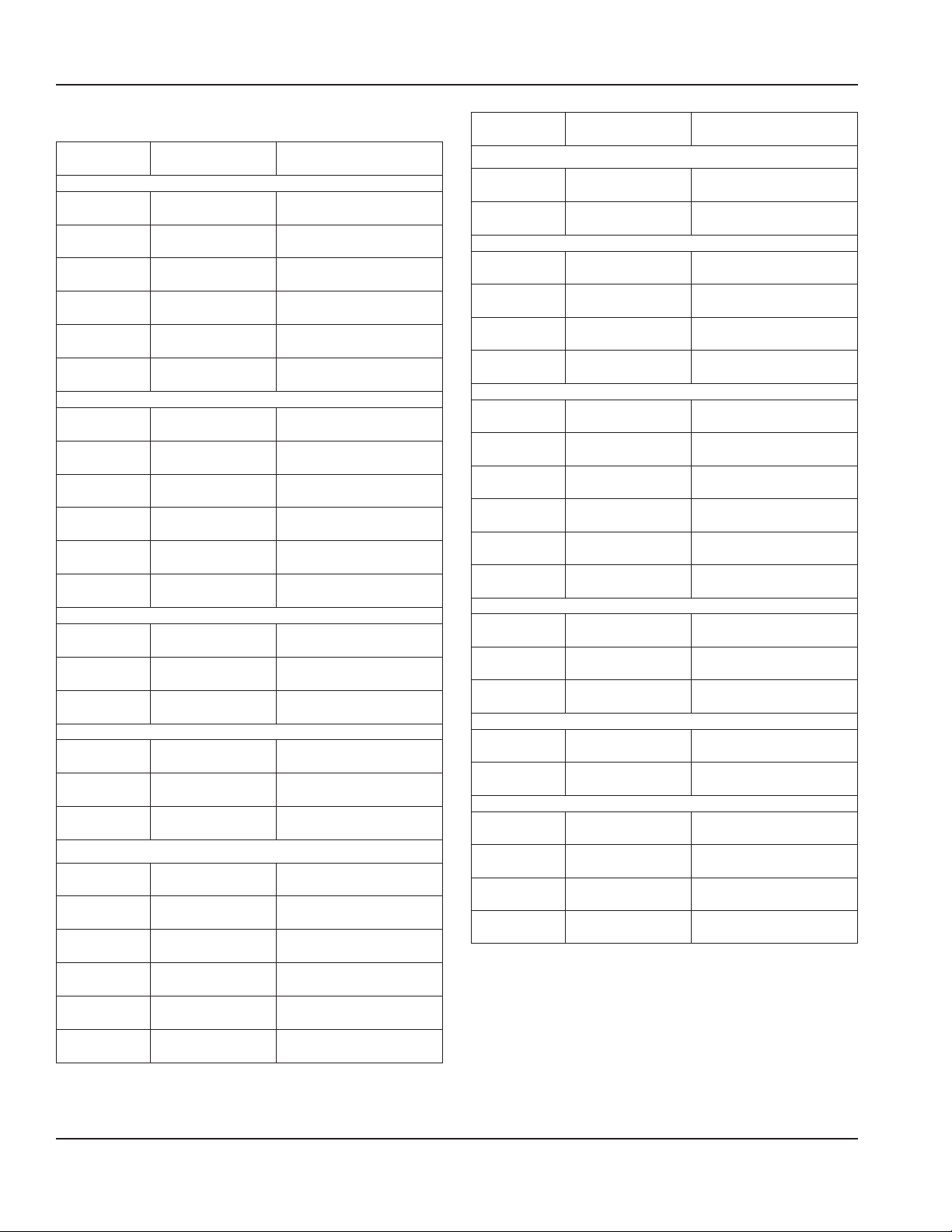
Installation Section 2
Cutout Installation Dimensions
Model Counter Cutout
Dimensions
8100-EFP Series
8118-EFP 17” x 25”
(43cm x 64cm)
8132-EFP 30.75” x 25”
(78cm x 64cm)
8145-EFP 44.25” x 25”
(112cm x 64cm)
8159-EFP 57.87” x 25”
(147cm x 64cm)
8172-EFP 71.5” x 25”
(182cm x 64cm)
8186-EFP 85” x 25”
(216cm x 64cm)
8100-EF-E Export Series
8118-EF-E 17” x 25”
(43cm x 64cm)
8132-EF-E 30.75” x 25”
(78cm x 64cm)
8145-EF-E 44.25” x 25”
(112cm x 64cm)
8159-EF-E 57.87” x 25”
(147cm x 64cm)
8172-EF-E 71.5” x 25”
(182cm x 64cm)
8186-EF-E 85” x 25”
(216cm x 64cm)
8100-EFNP Series
8148-EFNP 46.88” x 17.25”
(119cm x 44cm)
8169-EFNP 68.5” x 17.25”
(174cm x 44cm)
8191-EFNP 90” x 17.25”
(229cm x 44cm)
8100-EFN-E Export Series
8148-EFN-E 46.88” x 17.25”
(119cm x 44cm)
8169-EFN-E 68.5” x 17.25”
(174cm x 44cm)
8191-EFN-E 90” x 17.25”
(229cm x 44cm)
N8000 Series
N8018
N8030
N8043
N8056
N8069
N8081
17” x 25”
(43cm x 64cm)
29.75” x 25”
(76cm x 64cm)
42.5” x 25”
(108cm x 64cm)
55.25” x 25”
(140cm x 64cm)
68” x 25”
(173cm x 64cm)
80.75” x 25”
(205cm x 64cm)
Control Panel Cutout
Dimensions
NA
NA
NA
NA
NA
NA
NA
NA
NA
NA
NA
NA
NA
NA
NA
NA
NA
NA
NA
NA
NA
NA
NA
NA
Model Counter Cutout
Dimensions
N8000N Series
N8046N
N8068N
N8044-R See drawing on
N8059-R See drawing on
N8076-R See drawing on
N8094-R See drawing on
N8118BP 17” X 25”
N8130BP 29.75” x 25”
N8143BP 42.50” X 25”
N8156BP 55.25” x 25”
N8169BP 68” X 25”
N8181BP 80.75” x 25”
N8118B-E 17” X 25”
N8130B-E 29.75” x 25”
N8143B-E 42.50” X 25”
N8156B-E 55.25” x 25”
N8169B-E 68” X 25”
N8144-BRP See drawing on
N8159-BRP See drawing on
N8176-BRP See drawing on
N8194-BRP See drawing on
45.75” x 17”
(116cm x 43cm)
66.50” x 17”
(169cm x 43cm)
N8000-R Series
page 17
page 17
page 17
page 17
N8100BP Series
(43cm x 64cm)
(76cm x 64cm)
(108cm x 64cm)
(140cm x 64cm)
(173cm x 64cm)
(205cm x 64cm)
N8100B-E Export Series - R404A
(43cm x 64cm)
(76cm x 64cm)
(108cm x 64cm)
N8100B-E Export Series - R134A
(140cm x 64cm)
(173cm x 64cm)
N8100-BRP Series
page 17
page 17
page 17
page 17
Control Panel Cutout
Dimensions
NA
NA
NA
NA
NA
NA
NA
NA
NA
NA
NA
NA
NA
NA
NA
NA
NA
NA
NA
NA
NA
14 Part Number: 9291458C 07/22
Page 15
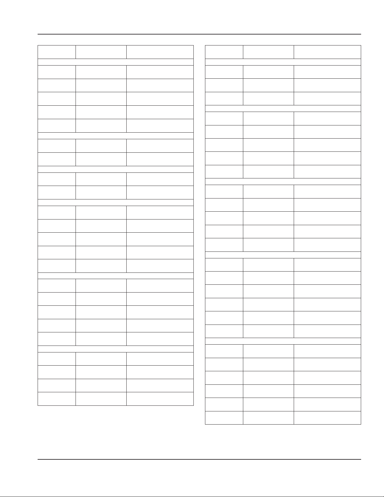
Section 2 Installation
Model Counter Cutout
Dimensions
N8100FAP Series
N8131-FAP 30.25” x 25.5”
(77cm x 65cm)
N8144-FAP 43” x 25.5”
109cm x 65cm)
N8157-FAP 55.75” x 25.5”
(142cm x 65cm)
N8169-FAP 68.5” x 25.5”
174cm x 65cm)
N8182-FAP 81.25” x 25.5”
(206cm x 65cm)
N8100NBP Series
N8146NBP 45.75” x 17”
(116cm x 43cm)
N8168NBP 66.5” x 17”
(169cm x 43cm)
N8100NB-E Export Series
N8146NB-E 45.75” x 17”
(116cm x 43cm)
N8168NB-E 66.5” x 17”
(169cm x 43cm)
N8200P Series
N8231P 30.75” x 25"
(78cm x 64cm)
N8245P 44.63” x 25”
(113cm x 64cm)
N8259P 58.50” x 25”
(149cm x 64cm)
N8273P 72.38” x 25”
(184cm x 64cm)
N8287P 86.25” x 25”
(219cm x 64cm)
N8200-E Export Series
N8231-E 30.75” x 25"
(78cm x 64cm)
N8245-E 44.63” x 25”
(113cm x 64cm)
N8259-E 58.50” x 25”
(149cm x 64cm)
N8273-E 72.38” x 25”
(184cm x 64cm)
N8287-E 86.25” x 25”
(219cm x 64cm)
N8200GP Series
N8231GP 30.75” X 25”
(78cm x 64cm)
N8245GP 44.63” x 25”
(113cm x 64cm)
N8259GP 58.5” x 25”
(149cm x 64cm)
N8273GP 72.38” x 25”
(184cm x 64cm)
Control Panel Cutout
Dimensions
NA
NA
NA
NA
NA
NA
NA
NA
NA
NA
NA
NA
NA
NA
NA
NA
NA
NA
NA
NA
NA
NA
NA
Model Counter Cutout
Dimensions
N8200G-E Export Series
N8231G-E 30.75” X 25”
(78cm x 64cm)
N8245G-E 44.63” x 25”
(113cm x 64cm)
N8259G-E 58.5” x 25”
(149cm x 64cm)
N8200-STP Series
N8230-STP 28.60” x 21.10"
(73cm x 54cm)
N8240-STP 38.65” x 28.75”
(98cm x 73cm)
N8256-STP 54.60” x 21.10”
(139cm x 54cm)
N8258-STP 56.60” x 28.75”
(144cm x 73cm)
N8275-STP 74.50" x 28.75"
(189cm x 73cm)
N8600P Series
N8630P 29.75” X 25”
(76cm x 64cm)
N8643P 42.50” x 25”
(108cm x 64cm)
N8656P 55.25” x 25”
(140cm x 64cm)
N8669P 68” x 25”
(173cm x 64cm)
N8681P 80.75” x 25”
(205cm x 64cm)
N8700D Series
N8717-D 16.88” X 25”
(43cm x 64cm)
N8731-D 30.75” x 25”
(78cm x 64cm)
N8745-D 44.62” x 25”
(113cm x 64cm)
N8759-D 58.5” x 25”
(149cm x 64cm)
N8773-D 72.37” x 25”
(184cm x 64cm)
N8787-D 86.25” x 25”
(219cm x 64cm)
N8700D-E Export Series
N8717-D-E 16.88” X 25”
(43cm x 64cm)
N8731-D-E 30.75” x 25”
(78cm x 64cm)
N8745-D-E 44.62” x 25”
(113cm x 64cm)
N8759-D-E 58.5” x 25”
(149cm x 64cm)
N8773-D-E 72.37” x 25”
(184cm x 64cm)
N8787-D-E 86.25” x 25”
(219cm x 64cm)
Control Panel Cutout
Dimensions
NA
NA
NA
NA
NA
NA
NA
NA
12.25” x 4.25” x 7”
(31cm x 11cm x 18cm)
12.25” x 4.25” x 7”
(31cm x 11cm x 18cm)
12.25” x 4.25” x 7”
(31cm x 11cm x 18cm)
12.25” x 4.25” x 7”
(31cm x 11cm x 18cm)
12.25” x 4.25” x 7”
(31cm x 11cm x 18cm)
7” x 4.62” x 7”
(18cm x 12cm x 18cm)
10.31” x 4.62” x 7”
(26cm x 12cm x 18cm)
14.5” x 4.62” x 7”
(37cm x 12cm x 18cm)
18.69” x 4.62” x 7”
(47cm x 12cm x 18cm)
22.88” x 4.62” x 7”
(58cm x 12cm x 18cm)
27” x 4.62” x 7”
(69cm x 12cm x 18cm)
7” x 4.62” x 7”
(18cm x 12cm x 18cm)
10.31” x 4.62” x 7”
(26cm x 12cm x 18cm)
14.5” x 4.62” x 7”
(37cm x 12cm x 18cm)
18.69” x 4.62” x 7”
(47cm x 12cm x 18cm)
22.88” x 4.62” x 7”
(58cm x 12cm x 18cm)
27” x 4.62” x 7”
(69cm x 12cm x 18cm)
Part Number: 9291458C 07/22 15
Page 16
Installation Section 2
Model Counter Cutout
Dimensions
N8700DESP Series
N8717-DESP 16.87” X 25”
(43cm x 64cm)
N8731-DESP 30.75” x 25”
(78cm x 64cm)
N8745-DESP 44.62” x 25”
(113cm x 64cm)
N8759-DESP 58.50” x 25”
(149cm x 64cm)
N8773-DESP 72.37” x 25”
(184cm x 64cm)
N8787-DESP 86.25” x 25”
(219cm x 64cm)
N8700-D-ESP-E Export Series
N8717-D-ESP-E 16.87” X 25”
(43cm x 64cm)
N8731-D-ESP-E 30.75” x 25”
(78cm x 64cm)
N8745-D-ESP-E 44.62” x 25”
(113cm x 64cm)
N8759-D-ESP-E 58.50” x 25”
(149cm x 64cm)
N8773-D-ESP-E 72.37” x 25”
(184cm x 64cm)
N8787-D-ESP-E 86.25” x 25”
(219cm x 64cm)
N8700N Series
N8746ND 44.62” x 15.0”
(113cm x 38cm)
N8768N 66.50” x 15.0”
(169cm x 38cm)
N8768ND 66.50” x 15.0”
(169cm x 38cm)
N8700-R Series
N8744-R See drawing on
page 17
N8759-R See drawing on
page 17
N8776-R See drawing on
page 17
N8794-R See drawing on
page 17
N8800 Series
N8831 30.75” X 25”
(78cm x 64cm)
N8845 44.63” x 25”
(113cm x 64cm)
N8859 58.5” x 25”
(149cm x 64cm)
N8873 72.38” x 25”
(184cm x 64cm)
N8887 86.25” x 25”
(219cm x 64cm)
Control Panel Cutout
Dimensions
5” x 6.88” x 7.50”
(13cm x 17cm x 19cm)
5” x 11.88” x 7.50”
(13cm x 30cm x 19cm)
5” x 17.38” x 7.50”
(13cm x 44cm x 19cm)
5” x 22.88” x 7.50”
(13cm x 58cm x 19cm)
5” x 28.38” x 7.50”
(13cm x 72cm x 19cm)
5” x 33.88”x 7.50”
(13cm x 86cm x 19cm)
5” x 6.88” x 7.50”
(13cm x 17cm x 19cm)
5” x 11.88” x 7.50”
(13cm x 30cm x 19cm)
5” x 17.38” x 7.50”
(13cm x 44cm x 19cm)
5” x 22.88” x 7.50”
(13cm x 58cm x 19cm)
5” x 28.38” x 7.50”
(13cm x 72cm x 19cm)
5” x 33.88”x 7.50”
(13cm x 86cm x 19cm)
10.31” x 4.62” x 7”
(26cm x 12cm x 18cm)
14.50” x 4.62” x 7”
(37cm x 12cm x 18cm)
14.50” x 4.62” x 7”
(37cm x 12cm x 18cm)
10.31” x 4.62” x 7”
(26cm x 12cm x 18cm)
14.5” x 4.62” x 7”
(37cm x 12cm x 18cm)
18.69” x 4.62” x 7”
(47cm x 12cm x 18cm)
22.88” x 4.62” x 7”
(58cm x 12cm x 18cm)
12.25” x 4.25” x 7”
(31cm x 11cm x 18cm)
12.25” x 4.25” x 7”
(31cm x 11cm x 18cm)
12.25” x 4.25” x 7”
(31cm x 11cm x 18cm)
12.25” x 4.25” x 7”
(31cm x 11cm x 18cm)
12.25” x 4.25” x 7”
(31cm x 11cm x 18cm)
Model Counter Cutout
Dimensions
N8800-E Export Series
N8831-E 30.75” X 25”
(78cm x 64cm)
N8845-E 44.63” x 25”
(113cm x 64cm)
N8859-E 58.5” x 25”
(149cm x 64cm)
N8873-E 72.38” x 25”
(184cm x 64cm)
N8887-E 86.25” x 25”
(219cm x 64cm)
Control Panel Cutout
Dimensions
12.25” x 4.25” x 7”
(31cm x 11cm x 18cm)
12.25” x 4.25” x 7”
(31cm x 11cm x 18cm)
12.25” x 4.25” x 7”
(31cm x 11cm x 18cm)
12.25” x 4.25” x 7”
(31cm x 11cm x 18cm)
12.25” x 4.25” x 7”
(31cm x 11cm x 18cm)
† Drop-In FlexiWell & FlexiTop Models N8600-FWP and
N8200-FTP are within the FlexiWell manual 9291544
16 Part Number: 9291458C 07/22
Page 17
Section 2 Installation
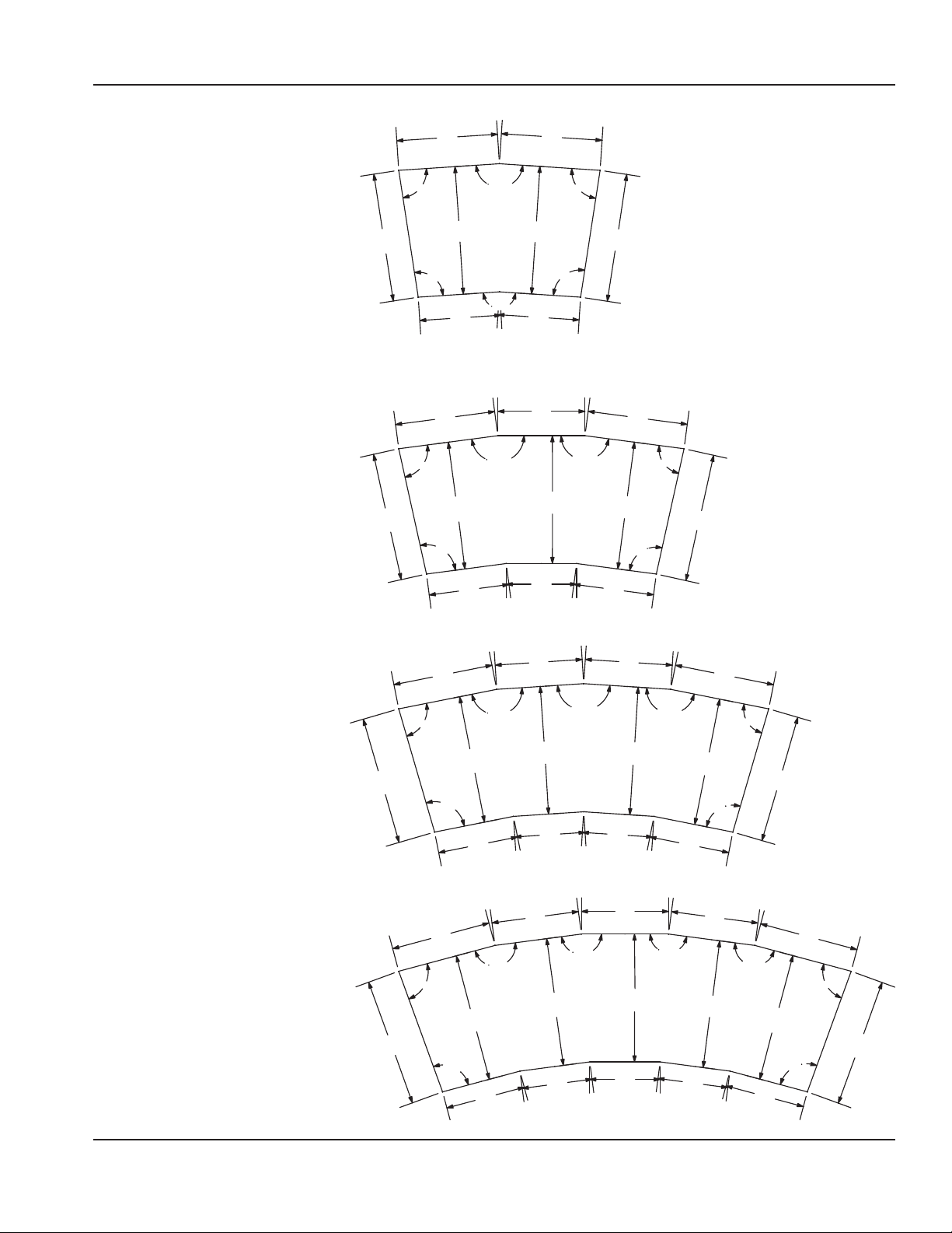
CURVED DROPIN CUTOUT DETAILS
2 pan standard curved drop-in cutout detail
for models:
• N8044-R
• N8144-BRP
• N8744-R
3 pan standard curved drop-in cutout detail
for models:
• N8059-R
• N8159-BRP
• N8759-R
25.10”
64cm
25.10”
64cm
85˚
85˚
95˚
19.75”
50cm
19.56”
50cm
95˚
25.00”
64cm
15.92”
40cm
25.00”
64cm
172.50˚
172.50˚
172.50˚
25.00”
64cm
15.92”
40cm
17.06”
43cm
19.75”
50cm
25.00”
64cm
95˚
85˚
172.50˚
25.10”
64cm
25.00”
64cm
19.56”
50cm
95˚
85˚
25.10”
64cm
4 pan standard curved drop-in cutout detail
for models:
• N8076-R
• N8176-BRP
• N8776-R
5 pan standard curved drop-in cutout detail
or models:
• N8094-R
• N8194-BRP
• N8794-R
25.10”
64cm
25.10”
64cm
85˚
172.50˚
172.50˚
13.78”
35cm
17.06”
43cm
25.00”
64cm
17.06”
43cm
13.78”
35cm
25.00”
64cm
13.78”
35cm
15.73”
40cm
19.56”
50cm
25.00”
64cm
95˚
15.73”
40cm
19.50”
50cm
85˚
25.00”
64cm
95˚
15.67”
40cm
172.50˚
172.50˚
15.73”
40cm
13.78”
35cm
17.06”
43cm
13.78”
35cm
17.06”
43cm
25.00”
64cm
25.00”
64cm
172.50˚
172.50˚
15.73”
40cm
13.78”
35cm
25.00”
64cm
17.06”
43cm
25.00”
64cm
19.56”
50cm
95˚
85˚
172.50˚
25.00”
64cm
15.67”
40cm
25.10”
64cm
95˚
19.50”
50cm
85˚
25.10”
64cm
Part Number: 9291458C 07/22 17
Page 18
Installation Section 2
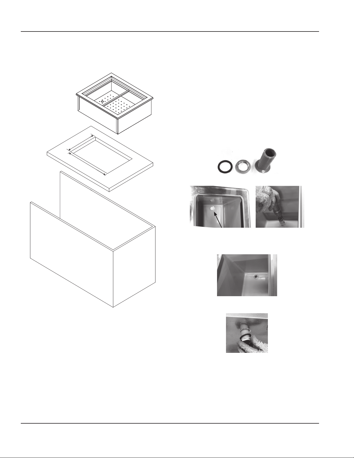
Counter Cutout Dimensions
Are Model Specic
Drop-In Counter Installation
ICE COOLED DROPIN UNITS
N8000, N8000N, N8000-R
1. Place the ice cooled drop-in unit through the counter
cutout.
2. A gasket is installed in the flange of each unit.
The weight of the unit on the gasket forms a seal
preventing liquids from seeping into the cut-out
opening.
3. The 1” diameter drain on N8000, N8000N, N8000-R
models is shipped loose and must be connected during
installation.
A. Provided 1” (25mm) drain, nut and washer must
be field installed to an appropriate container or
floor drain following local code requirements.
Sinks come standard with 1-1/2” basket strainer
assemblies.
B. Remove/drill foam out of drain hole.
C. Apply thin ring of plumbers putty around the
drain.
D. From the inside drop the drain into the drain hole.
E. From the outside secure the drain with the washer
and nut.
F. Tighten the nut with channel locks, use a fork to
hold the drain in place if necessary.
G. Clean up excess plumbers putty.
18 Part Number: 9291458C 07/22
Page 19
Section 2 Installation
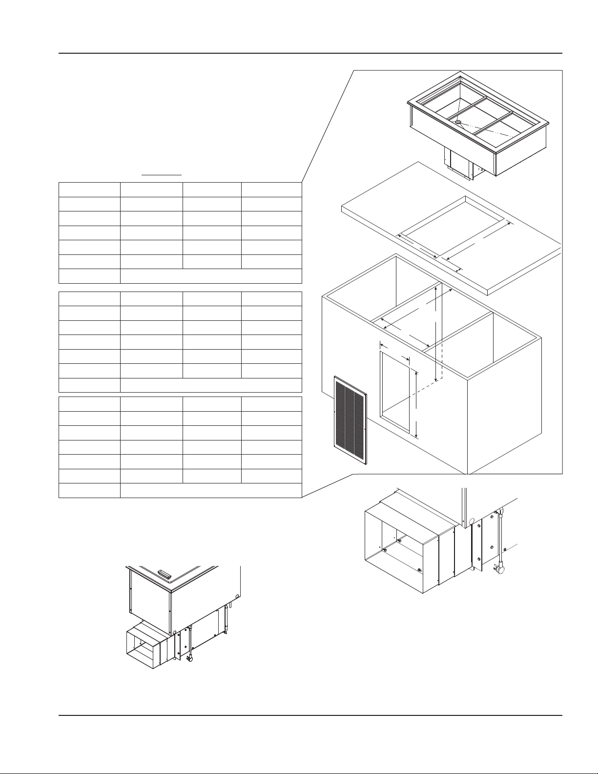
SELFCONTAINED REFRIGERATED DROPIN UNITS
8100-EFNP, N8100BP
For any non-standard installation consult the factory.
1. Install a GFCI receptacle a minimum of 14” (36cm) up
from the cabinet bottom inside the partitions. We
recommend installing a remote located power switch
for ease of use.
2. Cabinet interior minimum dimensions:
Dimension 8148-EFNP N8168-EFNP 8191-EFNP
A 46.87"/199cm 68.5"/174cm 90"/229cm
B 19"/48cm 19"/48cm 19"/48cm
C 26"/66cm 26"/66cm 26"/66cm
D 46.87”/199cm 68.5”/174cm 90"/229cm
E 17.25"/44cm 17.25"/44cm 17.25"/44cm
F Min. 2.75”/7cm - Max. 4.75”/12cm
D
E
F
Dimension N8118BP N8130BP N8143BP
A 22.38"/57cm 29.75"/76cm 42.5"/108cm
B 27.75"/70cm 27.75"/70cm 27.75"/70cm
C 26"/66cm 26"/66cm 26"/66cm
D 17"/43cm 29.75"/76cm 42.5"/108cm
E 25"/64cm 25"/64cm 25"/64cm
F Min. 2.75”/7cm - Max. 4.75”/12cm
Dimension N8156BP N8169BP N8181BP
A 55.25"/140cm 68"/173cm 80.75"/205cm
B 27.75"/70cm 27.75"/70cm 27.75"/70cm
C 26"/66cm 26"/66cm 26"/66cm
D 55.25"/140cm 68"/173cm 80.75"/205cm
E 25"/64cm 25"/64cm 25"/64cm
F Min. 2.75”/7cm - Max. 4.75”/12cm
3. Place the condensing unit through the counter cutout.
4. Extend the telescoping duct from the front of the
condensing unit to the back of the louver. This will
prevent recirculation of discharge air. Export models do
not have a telescoping duct, skip to step 6.
11.50”
(29cm)
B
C
A
22.50”
(57cm)
Use Screws to Secure Desired Depth
3 of 8 Screws Shown
6. Partitions must fully extend front to back and top to
bottom.
7. Louver cutout must extend to bottom of cabinet and
5. Put eight provided screws through the telescoping
duct side walls to hold it at the desired depth.
align with condenser face.
NOTE: The louver provided must be installed in front of
Part Number: 9291458C 07/22 19
Page 20
Installation Section 2
the condensing unit’s finned coil. Any restriction to the
proper air flow will void the compressor warranty.
• Louver measures 13.00” x 25.00” (33cm x 64cm).
• Louver Cutout Size is 11.50” x 22.50” (29cm x 57cm)
(typical installation).
Louver
Duct
Finned Coil
Partitions Not Shown
Typical Counter Cabinet
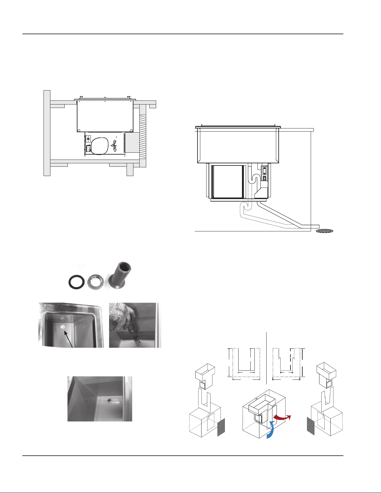
8. The 1” diameter drain on N8100BP, N8100-EFNP
and N8100P models is shipped loose and must be
connected during installation.
A. Provided 1” (25mm) drain, nut and washer must
be field installed to an appropriate container or
floor drain following local code requirements.
Sinks come standard with 1-1/2” basket strainer
assemblies.
B. Remove/drill foam out of drain hole.
F. Tighten the nut with channel locks, use a fork to
hold the drain in place if necessary.
G. Clean up excess plumbers putty.
Suggested Drainage Trap
Units may increase in performance if they have a
drainage trap or shut-off valve installed. Installing the
trap will stop warm air being introduced into the dry
well of the unit.
Rotating Condensing Unit
If the condensing unit is to be rotated 90 degrees you
will need to supply an air flow divider which would
be based on size of cabinet.
• Divider must partition cabinet on left and right
side of louver to eliminate air recirculation.
• Divider to run the full height and width of the
cabinet with cutout in the middle to accept drop-in.
• Divider can be made with any availible material
C. Apply thin ring of plumbers putty around the
drain.
D. From the inside drop the drain into the drain hole.
8118-EFP Air Divider Build
Customer is responsible
N8118BP Air Divider Build
Customer is responsible
E. From the outside secure the drain with the washer
and nut.
20 Part Number: 9291458C 07/22
Page 21
Section 2 Installation
SELFCONTAINED REFRIGERATED DROPIN UNITS
8100BRP, N8100-EFP
For any non-standard installation consult the factory.
1. Install a GFCI receptacle a minimum of 14” (36cm) up
from the cabinet bottom inside the partitions. We
recommend installing a remote located power switch
for ease of use.
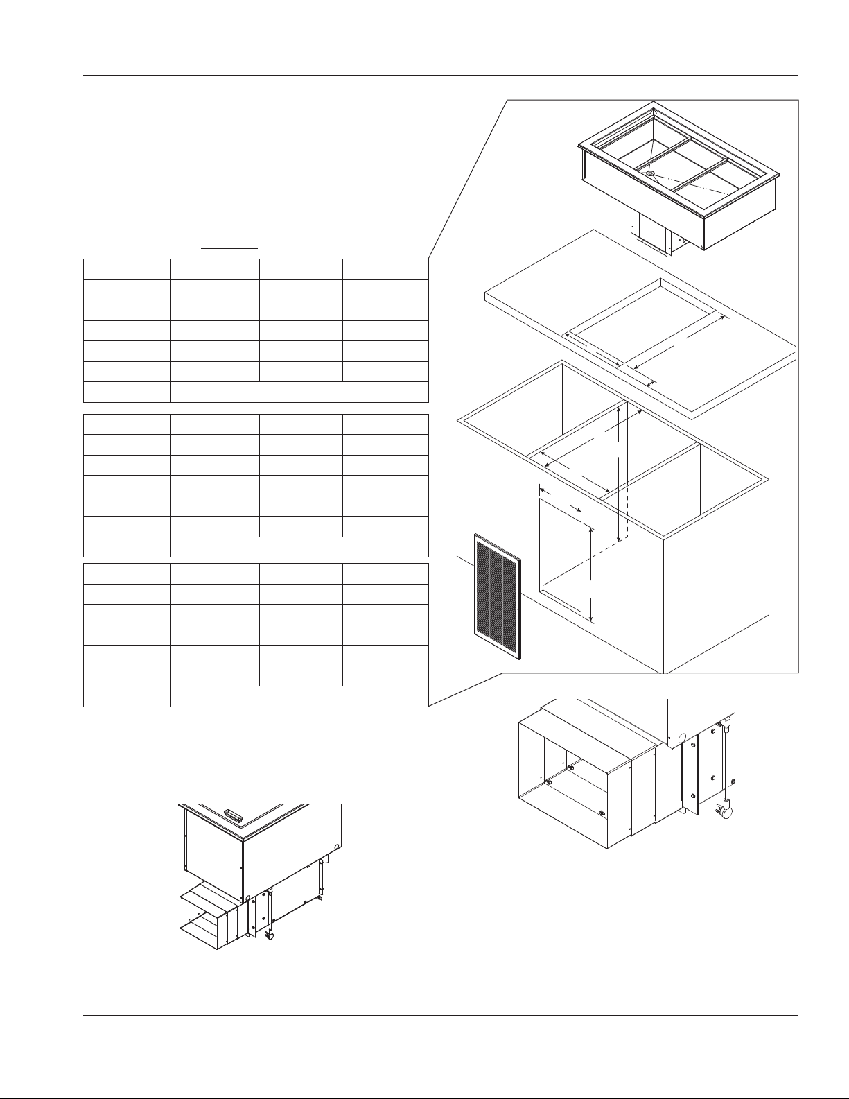
2. Cabinet interior minimum dimensions:
Dimension N8146BRP N8168BRP
A 45.75"/116cm 66.5"/169cm
B 19"/48cm 19"/48cm
C 26"/66cm 26"/66cm
D 45.75/116cm 66.5"/169cm
E 17"/43cm 17"/43cm
F Min. 2.75”/7cm - Max. 4.75”/12cm
D
E
F
Dimension N8118-EFP N8132-EFP N8145-EFP
A 22.38"/57cm 30.75"/78cm 44.25"/112cm
B 27.75"/70cm 27.75"/70cm 27.75"/70cm
C 26"/66cm 26"/66cm 26"/66cm
D 17"/43cm 30.75"/78cm 44.25"/112cm
E 25"/64cm 25"/64cm 25"/64cm
F Min. 2.75”/7cm - Max. 4.75”/12cm
Dimension N8159-EFP N8172-EFP N8186_EFP
A 57.87"/147cm 71.5"/182cm 85"/216cm
B 27.75"/70cm 27.75"/70cm 27.75"/70cm
C 26"/66cm 26"/66cm 26"/66cm
D 57.87"/147cm 71.5"/182cm 85"/216cm
E 25"/64cm 25"/64cm 25"/64cm
F Min. 2.75”/7cm - Max. 4.75”/12cm
3. Place the condensing unit through the counter cutout.
4. Extend the telescoping duct from the front of the
condensing unit to the back of the louver. This will
prevent recirculation of discharge air. Export models do
not have a telescoping duct, skip to step 6.
11.50”
(29cm)
B
C
A
22.50”
(57cm)
Use Screws to Secure Desired Depth
3 of 8 Screws Shown
6. Partitions must fully extend front to back and top to
bottom.
7. Louver cutout must extend to bottom of cabinet and
5. Put eight provided screws through the telescoping
duct side walls to hold it at the desired depth.
align with condenser face.
NOTE: The louver provided must be installed in front of
Part Number: 9291458C 07/22 21
Page 22
Installation Section 2
the condensing unit’s finned coil. Any restriction to the
proper air flow will void the compressor warranty.
• Louver measures 13.00” x 25.00” (33cm x 64cm).
• Louver Cutout Size is 11.50” x 22.50” (29cm x 57cm)
(typical installation).
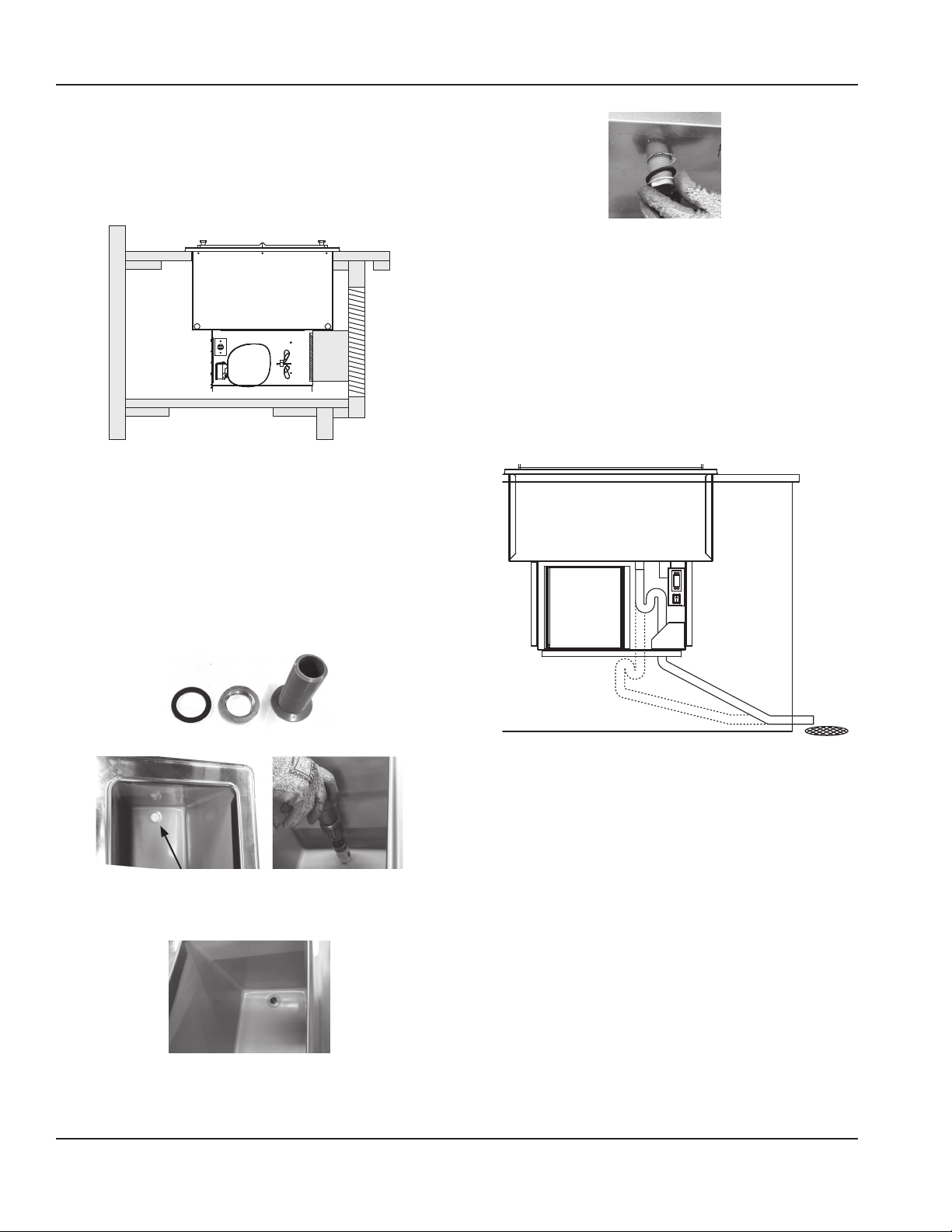
F. Tighten the nut with channel locks, use a fork to
hold the drain in place if necessary.
G. Clean up excess plumbers putty.
Louver
Duct
Finned Coil
Partitions Not Shown
Typical Counter Cabinet
8. The 1” diameter drain on N8100-BRP and N8100EFP
models is shipped loose and must be connected during
installation.
A. Provided 1” (25mm) drain, nut and washer must
be field installed to an appropriate container or
floor drain following local code requirements.
Sinks come standard with 1-1/2” basket strainer
assemblies.
B. Remove/drill foam out of drain hole.
Suggested Drainage Trap
Units may increase in performance if they have a
drainage trap or shut-off valve installed. Installing the
trap will stop warm air being introduced into the dry
well of the unit.
C. Apply thin ring of plumbers putty around the
drain.
D. From the inside drop the drain into the drain hole.
E. From the outside secure the drain with the washer
and nut.
22 Part Number: 9291458C 07/22
Page 23
Section 2 Installation
SELFCONTAINED REFRIGERATED DROPIN UNITS
8100-FAP
For any non-standard installation consult the factory.
1. Install a GFCI receptacle a minimum of 14” (36cm) up
from the cabinet bottom inside the partitions. We
recommend installing a remote located power switch
for ease of use.
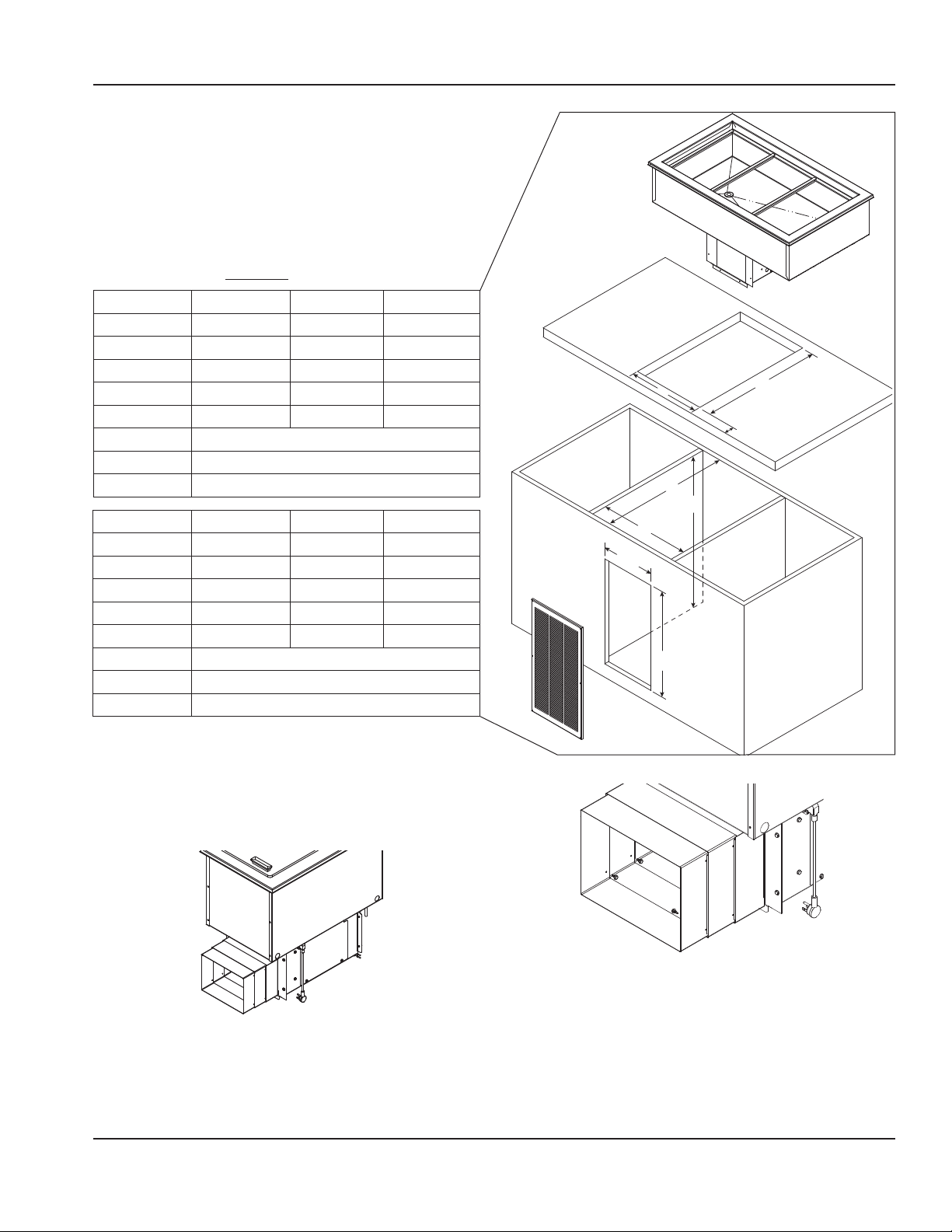
2. Cabinet interior minimum dimensions:
Dimension N8131-FAP N8144-FAP
A 30.25"/77cm 43"/109cm
B 27.75"/70cm 27.75"/70cm
C 26"/66cm 26"/66cm
D 30.25"/77cm 43"/109cm
E 25.5"/65cm 25.5”/65cm
F Min. 2.75”/7cm - Max. 4.75”/12cm
G 12”
H 23.50”
Dimension N8157-FAP N8169-FAP N8182-FAP
A 55.75"/142cm 68.5"/174cm 81.25"/206cm
B 27.75"/70cm 27.75"/70cm 27.75"/70cm
C 26"/66cm 26"/66cm 26"/66cm
D 55.75"/142cm 68.5"/174cm 81.25"/206cm
E 25.5"/65cm 25.5"/65cm 25.5"/65cm
F Min. 2.75”/7cm - Max. 4.75”/12cm
G 15.75”
H 23.50”
D
B
C
A
G
H
E
F
3. Place the condensing unit through the counter cutout.
4. Extend the telescoping duct from the front of the
condensing unit to the back of the louver. This will
prevent recirculation of discharge air. Export models do
not have a telescoping duct, skip to step 6.
Use Screws to Secure Desired Depth
3 of 8 Screws Shown
5. Put eight provided screws through the telescoping
duct side walls to hold it at the desired depth.
6. Partitions must fully extend front to back and top to
bottom.
7. Louver cutout must extend to bottom of cabinet and
align with condenser face.
NOTE: The louver provided must be installed in front of
Part Number: 9291458C 07/22 23
Page 24
Installation Section 2
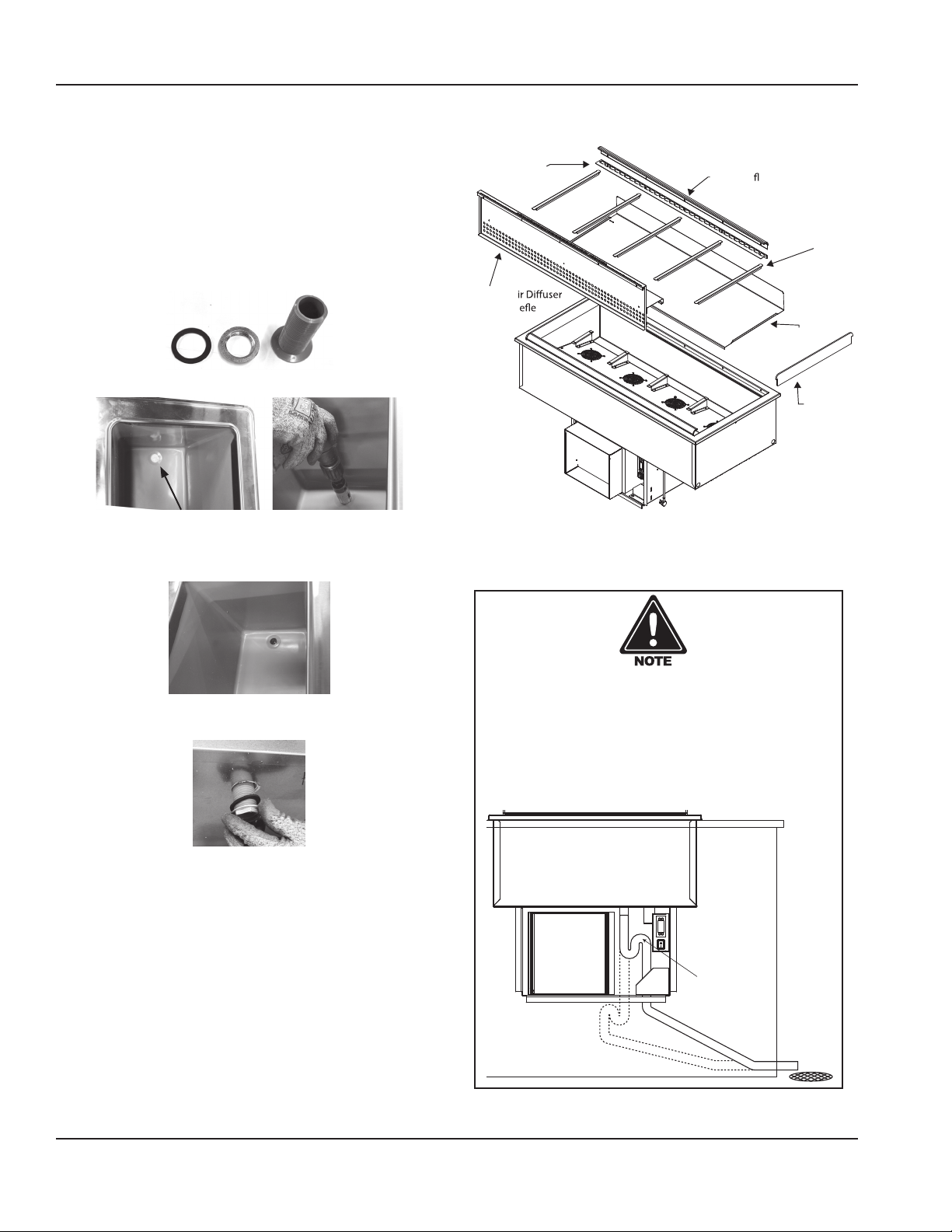
the 1” diameter drain on N8100-FAP models is shipped
loose and must be connected during installation.
N8157-FAP, N8169-FAP and N8182-FAP have two 1”
drains.
Perforated Pan Clip
Black Air
ow Extrusions
A. Provided 1” (25mm) drain, nut and washer must
be field installed to an appropriate container or
floor drain following local code requirements.
Adapter Bars
Sinks come standard with 1-1/2” basket strainer
assemblies.
Upright A
With Air D ctor
Coil Assembly
Cover
B. Remove/drill foam out of drain hole.
C. Apply thin ring of plumbers putty around the
drain.
D. From the inside drop the drain into the drain hole.
E. From the outside secure the drain with the washer
and nut.
Plexiglas
End Caps
FAP Drainage Trap
An FAP unit should have a drainage trap installed to
ensure proper operation. Failure to install the trap
will result in warm air being introduced into the
well of the unit. If not installed immediately under
the unit, the trap should be installed just below the
compressor frame.
F. Tighten the nut with channel locks, use a fork to
hold the drain in place if necessary.
G. Clean up excess plumbers putty.
8. Inside the well, the fan assembly has standoff brackets
with tabs. The tabs should be bent up.
9. Place the coil assembly cover slots over the bracket
Install drainage
trap on FAP units
tabs. This will secure the cover is in the correct location
and will not disrupt the air flow.
10. The upright air diffuser will only fit one way on the
drain side.
24 Part Number: 9291458C 07/22
Page 25
Section 2 Installation
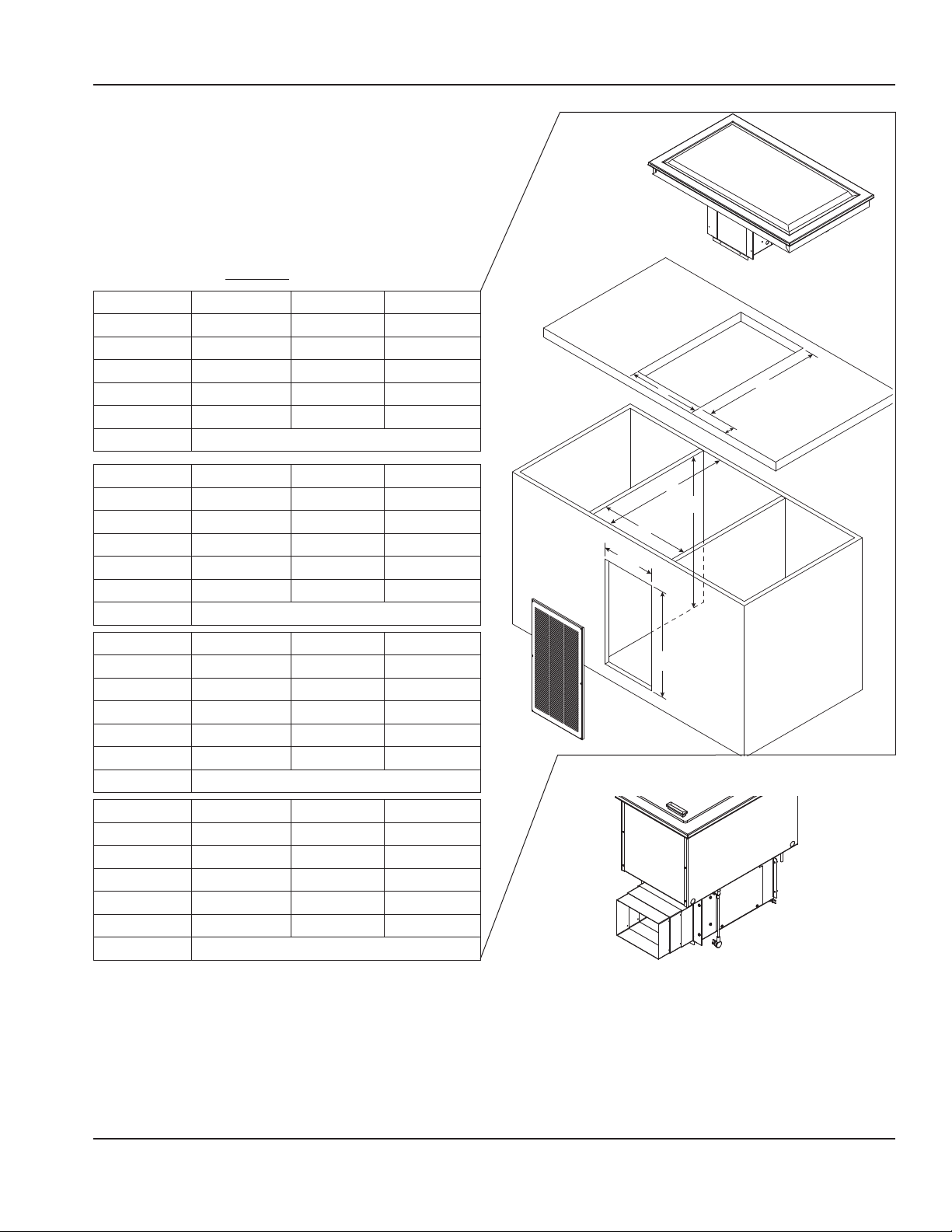
SELFCONTAINED REFRIGERATED DROPIN UNITS
8200P, N8200-GP, N8200-STP
For any non-standard installation consult the factory.
1. Install a GFCI receptacle a minimum of 14” (36cm) up
from the cabinet bottom inside the partitions. We
recommend installing a remote located power switch
for ease of use
2. Cabinet interior minimum dimensions:
Dimension N8231P/GP N8245P/GP N8259P/GP
A 30.75"/78cm 44.25"/112cm 58.5"/149cm
B 27.75"/70cm 27.75"/70cm 27.75"/70cm
C 26"/66cm 26"/66cm 26"/66cm
D 30.75"/78cm 44.25"/112cm 58.5"/149cm
E 25"/64cm 25"/64cm 25"/64cm
F Min. 2.75”/7cm - Max. 4.75”/12cm
D
E
F
Dimension N8273P/GP N8287P/GP
A 72.38"/184cm 86.25"/219cm
B 27.75"/70cm 27.75"/70cm
C 26"/66cm 26"/66cm
D 72.38"/184cm 86.25"/219cm
E 25"/64cm 25"/64cm
F Min. 2.75”/7cm - Max. 4.75”/12cm
Dimension N8230-STP N8240-STP N8256-STP
A 28.6"/73cm 38.65"/98cm 54.6"/139cm
B 27.75"/70cm 27.75"/70cm 27.75"/70cm
C 26"/66cm 26"/66cm 26"/66cm
D 28.6”/73cm 38.65”/98cm 54.6”/139cm
E 21.12"/54cm 28.75"/73cm 21.12"/54cm
F Min. 2.75”/7cm - Max. 4.75”/12cm
Dimension N8258-STP N8275-STP
A 56.6"/144cm 74.5"/189cm
B 27.75"/70cm 27.75"/70cm
C 26"/66cm 26"/66cm
D 56.6”/144cm 74.5”/189cm
E 28.75"/73cm 28.75"/73cm
F Min. 2.75”/7cm - Max. 4.75”/12cm
3. Place the condensing unit through the counter cutout.
4. Extend the telescoping duct from the front of the
condensing unit to the back of the louver. This will
prevent recirculation of discharge air. Export models do
not have a telescoping duct, skip to step 6.
B
C
A
11.50”
(29cm)
22.50”
(57cm)
5. Put eight provided screws through the telescoping
duct side walls to hold it at the desired depth.
Part Number: 9291458C 07/22 25
Page 26
Installation Section 2
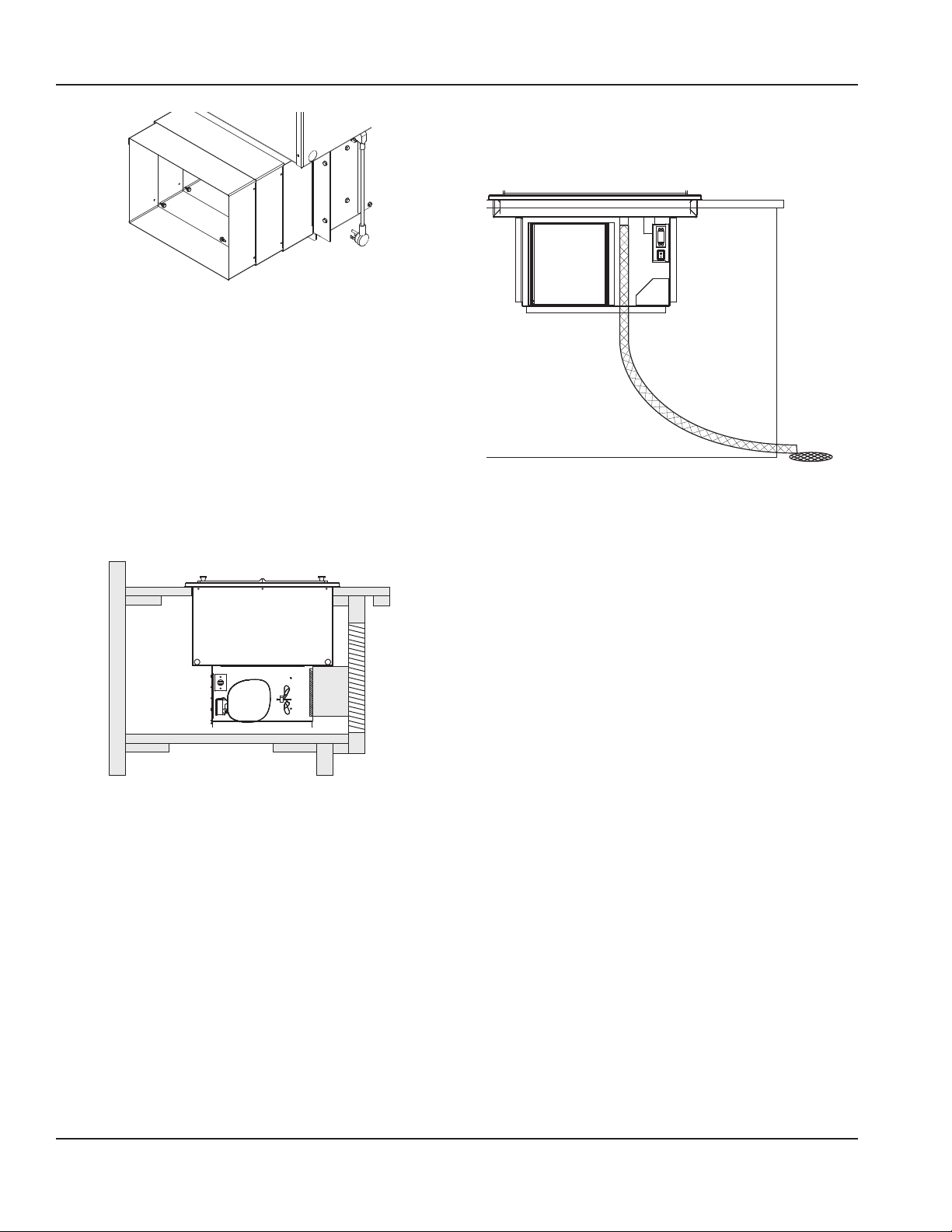
Drainage
N8200P and N8200-STP have a 1/2” drain.
N8200-GP have a 3/4” drain located on end/center.
Use Screws to Secure Desired Depth
3 of 8 Screws Shown
6. Partitions must fully extend front to back and top to
bottom.
7. Louver cutout must extend to bottom of cabinet and
align with condenser face.
NOTE: The louver provided must be installed in front of
the condensing unit’s finned coil. Any restriction to the
proper air flow will void the compressor warranty.
• Louver measures 13.00” x 25.00” (33cm x 64cm).
• Louver Cutout Size is 11.50” x 22.50” (29cm x 57cm)
(typical installation).
Partitions Not Shown
Louver
Duct
Finned Coil
† Drop-In FlexiWell & FlexiTop Models N8600-FWP and
N8200-FTP are within the FlexiWell manual 9291544
26 Part Number: 9291458C 07/22
Page 27
Section 2 Installation
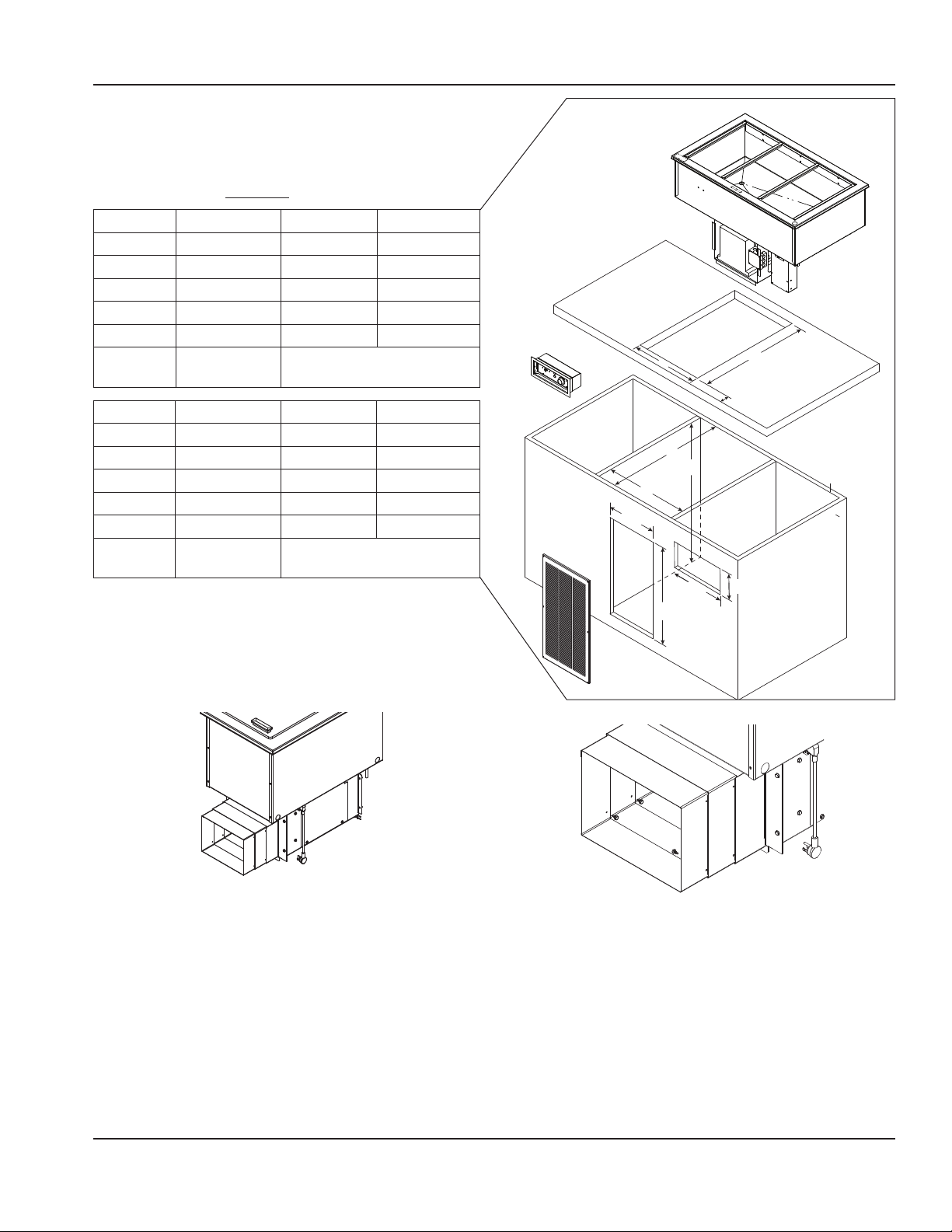
SELFCONTAINED COMBO HOT/COLD DROPIN UNITS
N8600P
For any non-standard installation consult the factory.
1. Cabinet interior minimum dimensions:
Dimension N8630P N8643P N8656P
A 29.75"/76cm 42.5"/108cm 55.25"/140cm
B 29"/74cm 29"/74cm 29"/74cm
C 28"/71cm 28"/71cm 28"/71cm
D 29.75"/76cm 42.5"/108cm 55.5"/140cm
E 25"/64cm 25"/64cm 25"/64cm
F 4.75”/12cm Min. 2.75”/7cm -
D
Max. 4.75”/12cm
F
Dimension N8669P N8681P N86120P
E
A 68"/173cm 80.75"/205cm 101.75"/258cm
B 29"/74cm 29"/74cm 29"/74cm
C 28"/71cm 28"/71cm 28"/71cm
D 68"/173cm 80.75"/205cm 101.75"/258cm
E 25"/64cm 25"/64cm 25"/64cm
18.50”
(47cm)
B
C
A
F 4.75”/12cm Min. 2.75”/7cm -
Max. 4.75”/12cm
4.25”
(11cm)
2. Place the condensing unit through the counter cutout.
22.50”
(57cm)
12.25”
(31cm)
3. Extend the telescoping duct from the front of the
condensing unit to the back of the louver. This will
prevent recirculation of discharge air. Export models do
not have a telescoping duct, skip to step 6.
4. Put eight provided screws through the telescoping
duct side walls to hold it at the desired depth.
Use Screws to Secure Desired Depth
3 of 8 Screws Shown
5. Partitions must fully extend front to back and top to
bottom.
6. Louver cutout must extend to bottom of cabinet and
align with condenser face.
NOTE: The louver provided must be installed in front of
Part Number: 9291458C 07/22 27
Page 28
Installation Section 2
NOTE: CONT: the condensing unit’s finned coil.
Any restriction to the proper air flow will void the
compressor warranty.
• Louver measures 20.00” x 25.00” (51cm x 64cm).
• Louver Cutout Size is 18.50” x 22.50” (47cm x 57cm)
(typical installation).
Louver
Duct
Finned Coil
Partitions Not Shown
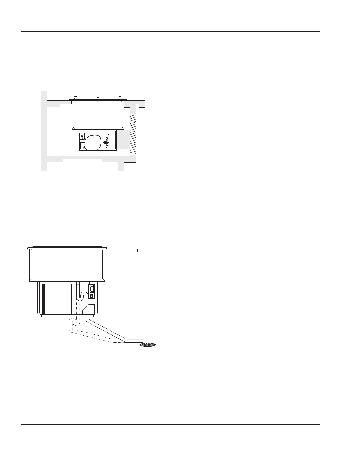
Suggested Drainage Trap
Units may increase in performance if they have a
drainage trap or shut-off valve installed. Installing the
trap will stop warm air being introduced into the dry
well of the unit.
NOTE: For units equipped with an Auto Fill system the
Auto Fill activation switch must be installed a minimum
of 14” up from the cabinet bottom.
NOTE: For units equipped with an Auto Fill system the
bottom of the unit must be a minimum of 4” up from
the cabinet bottom.
† Drop-In FlexiWell & FlexiTop Models N8600-FWP and
N8200-FTP are within the FlexiWell manual 9291544
28 Part Number: 9291458C 07/22
Page 29
Section 2 Installation
HOT FOOD WELL DROPIN UNITS
N8700-D, N8700-DESP, N8700N, N8700-R, N8800
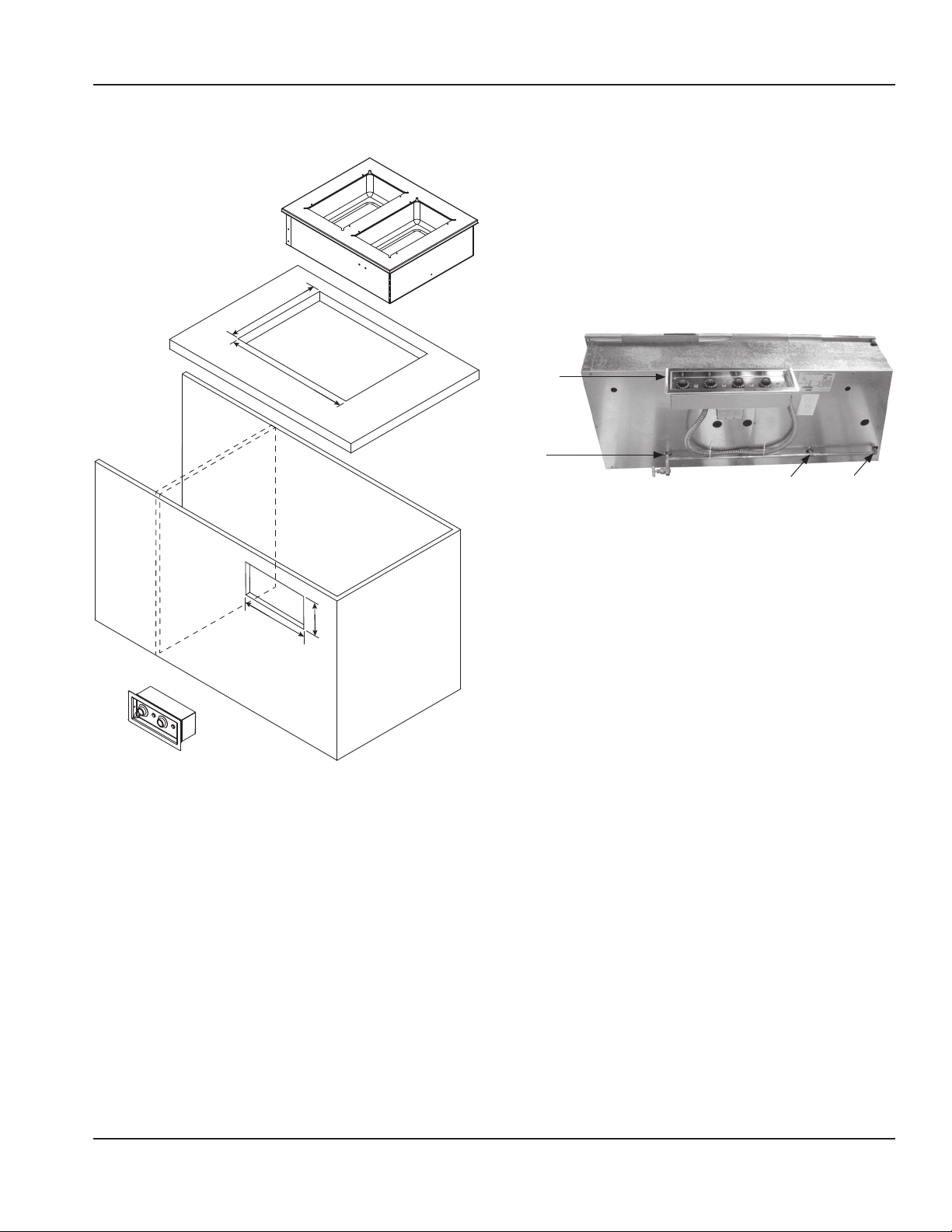
Counter Cutout Dimensions
Are Model Specic
Control Panel
Cutout Dimensions
Are Model Specic
1. Orient the control panel with the indicator light for
each control to the right of the control.
• N8700 series units have 48” (122cm) of conduit.
• N8800 Series units have 34” (86cm) of conduit.
2. N8700 control panel is designed to be installed on the
side opposite the drains.
• Installed on the same side as the drains, the control
panel will either be upside down or the knobs will
control the opposite wells.
Control
panel
installed
opposite
drains
Drains
Infinite control shown, directions also apply to digital control
3. Place the control panel into the cutout from inside the
cabinet. Place the collar into the cutout from outside
the cabinet. Secure with two screws.
4. Place the hot food well drop-in unit through the
counter cutout.
5. A gasket is installed in the flange of each unit.
The weight of the unit on the gasket forms a seal
preventing liquids from seeping into the cut-out
opening.
6. Plumb to a floor drain.
• All N8700 series are equipped with 1/2” (13mm)
female NPT drains, one per well located right rear
corner, manifold to 1/2” (13mm) gate valve.
• N8800 wells are sloped to a 1” (25mm) male NPT
stainless steel drain. Use a 1” female coupling.
Part Number: 9291458C 07/22 29
Page 30
Installation Section 2
Electrical Service
DANGER
Check all wiring connections, including factory
terminals, before operation. Connections can become
loose during shipment and installation.
Warning
n
This appliance must be grounded and all field wiring
must conform to all applicable local and national
codes. Refer to rating plate for proper voltage. It is the
responsibility of the end user to provide the disconnect
means to satisfy the authority having jurisdiction.
VOLTAGE
All electrical work, including wire routing and grounding,
must conform to local, state and national electrical codes.
The following precautions must be observed:
• The equipment must be grounded.
• A separate fuse/circuit breaker must be provided for
each unit.
• A qualified electrician must determine proper wire size
dependent upon location, materials used and length
of run (minimum circuit ampacity can be used to help
select the wire size).
• The maximum allowable voltage variation is ±10% of
the rated voltage at equipment start-up (when the
electrical load is highest).
• Check all green ground screws, cables and wire
connections to verify they are tight before start-up.
GROUND FAULT CIRCUIT INTERRUPTER
Ground Fault Circuit Interrupter (GFCI/GFI) protection is
a system that shuts down the electric circuit (opens it)
when it senses an unexpected loss of power, presumably
to ground. Manitowoc does not recommend the use of
GFCI/GFI circuit protection to energize our equipment. If
code requires the use of a GFCI/GFI then you must follow
the local code. The circuit must be dedicated, sized
properly and there must be a panel GFCI/GFI breaker. We
do not recommend the use of GFCI/GFI outlets to energize
our equipment as they are known for more intermittent
nuisance trips than panel breakers.
Note
These appliances will operate within the marked rated
voltage range without adjustment.
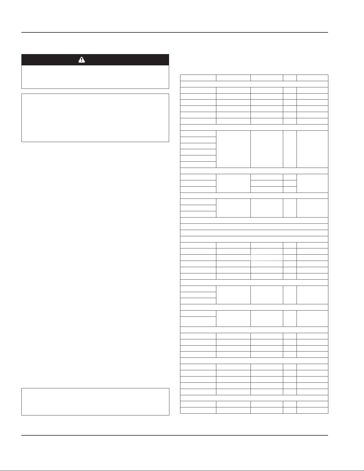
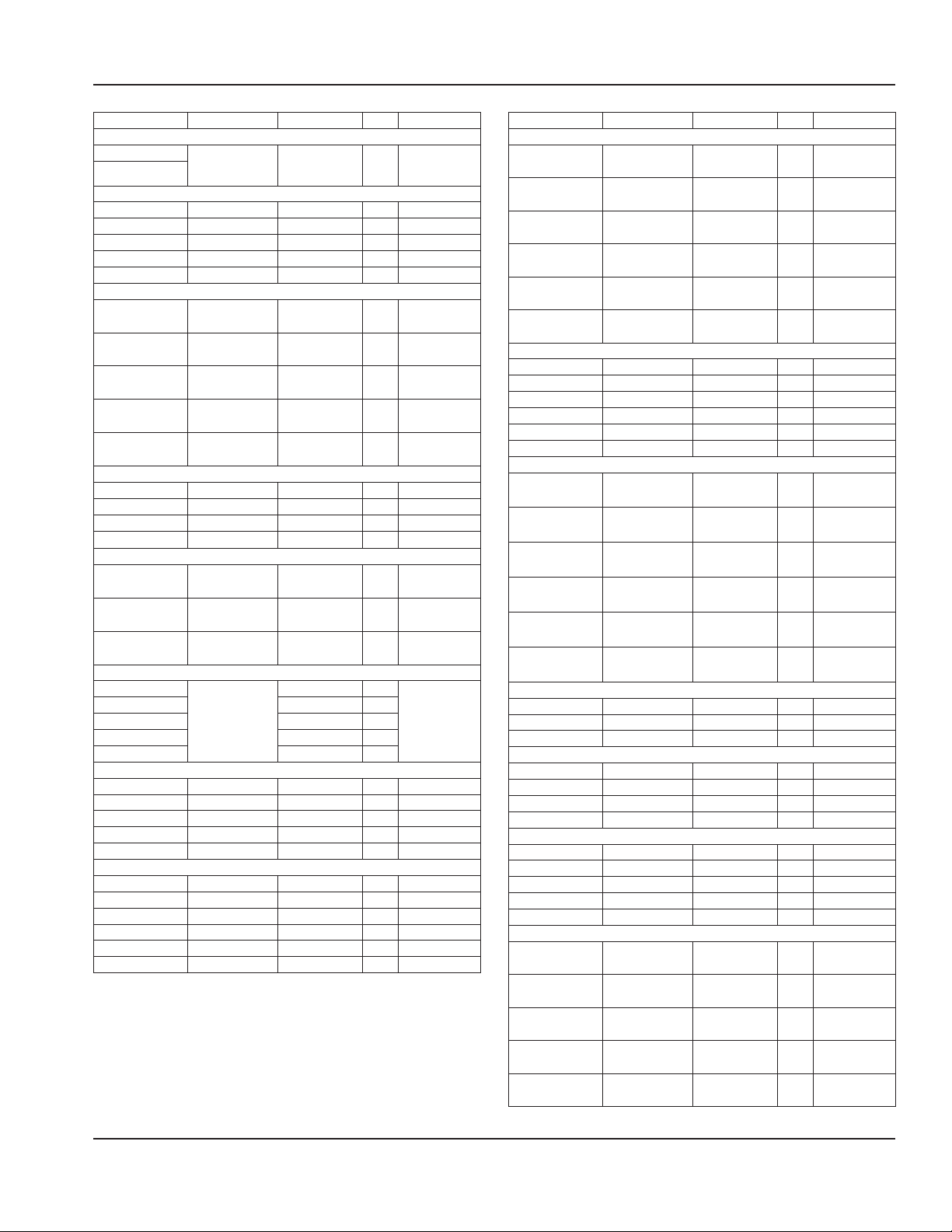
RATED AMPERAGES, HORSEPOWER, VOLTAGE &
POWER CORD CHART
Units with plugs are supplied with approximately 6ft
(183cm) cords.
Model V, Hz, Ph Amps H.P. Plug
8100-EFP Series R290
8118-EFP 115, 60, 1 2.4 1/5 NEMA 5-15P
8132-EFP 115, 60, 1 2.4 1/5 NEMA 5-15P
8145-EFP 115, 60, 1 3.7 1/4 NEMA 5-15P
8159-EFP 115, 60, 1 3.7 1/4 NEMA 5-15P
8172-EFP 115, 60, 1 4.8 1/3 NEMA 5-15P
8186-EFP 115, 60, 1 4.8 1/3 NEMA 5-15P
8100-EF-E Export Series
8118-EF-E
8132-EF-E
8145-EF-E
8159-EF-E
8172-EF-E
8186-EF-E
8148-EFNP
8191-EFNP 4.8 1/3
8148-EFN-E
8169-EFN-E
8191-EFN-E
N8118BP 115, 60, 1 2.0 1/5 NEMA 5-15P
N8130BP 115, 60, 1 2.0 1/5 NEMA 5-15P
N8143BP 115, 60, 1 3.1 1/4 NEMA 5-15P
N8156BP 115, 60, 1 3.1 1/4 NEMA 5-15P
N8169BP 115, 60, 1 3.1 1/4 NEMA 5-15P
N8181BP 115, 60, 1 4.6 1/3 NEMA 5-15P
N8118B-E
N8130B-E
N8143B-E
N8156B-E
N8169B-E
N8144-BRP 115, 60, 1 2.4 1/5 NEMA 5-15P
N8159-BRP 115, 60, 1 3.7 1/4 NEMA 5-15P
N8176-BRP 115, 60, 1 3.7 1/4 NEMA 5-15P
N8194-BRP 115, 60, 1 3.7 1/4 NEMA 5-15P
N8131-FAP 115, 60, 1 4.7 1/4 NEMA 5-15P
N8144-FAP 115, 60, 1 4.7 1/4 NEMA 5-15P
N8157-FAP 115, 60, 1 9.3 1/2 NEMA 5-15P
N8169-FAP 115, 60, 1 9.3 1/2 NEMA 5-15P
N8182-FAP 115, 60, 1 9.3 1/2 NEMA 5-15P
N8146NBP 115, 60, 1 2 1/5 NEMA 5-15P
N8168NBP 115, 60, 1 3.1 1/4 NEMA 5-15P
230-240, 50, 1
8100-EFNP Series R290
115, 60, 1
8100-EFN-E Export Series
230-240, 50, 1
N8000 Series - NA
N8000N Series - NA
N8000-R Series - NA
N8100BP Series - R290
N8100B-E Export Series - R404A
230-240, 50, 1
N8100B-E Export Series - R134A
230-240, 50, 1
N8100BRP Series - R290
N8100-FAP Series - R290
N8100NB Series - R290
2.5 Amps /
600 Watts
2.4 1/5
2.5 Amps /
600 Watts
1.5 Amps /
360 Watts
2.5 Amps /
600 Watts
1/4
1/4
1/5
1/4
Varies Per
Destination
NEMA 5-15P8169-EFNP 3.7 1/4
Varies Per
Destination
Varies Per
Destination
Varies Per
Destination
30 Part Number: 9291458C 07/22
Page 31
Section 2 Installation
Model V, Hz, Ph Amps H.P. Plug
N8100NB-E Export Series
N8146NB-E
N8168NB-E
N8231P 115, 60, 1 2.4 1/5 NEMA 5-15P
N8245P 115, 60, 1 2.4 1/5 NEMA 5-15P
N8259P 115, 60, 1 3.7 1/4 NEMA 5-15P
N8273P 115, 60, 1 3.7 1/4 NEMA 5-15P
N8287P 115, 60, 1 4.8 1/3 NEMA 5-15P
N8231-E 230-240, 50, 1 1.5 Amps /
N8245-E 230-240, 50, 1 1.5 Amps /
N8259-E 230-240, 50, 1 2.5 Amps /
N8273-E 230-240, 50, 1 2.5 Amps /
N8287-E 230-240, 50, 1 2.8 Amps /
N8231GP 115, 60, 1 2.4 1/5 NEMA 5-15P
N8245GP 115, 60, 1 3.7 1/4 NEMA 5-15P
N8259GP 115, 60, 1 4.8 1/3 NEMA 5-15P
N8273GP 115, 60, 1 4.8 1/3 NEMA 5-15P
N8231G-E 230-240, 50, 1 1.5 Amps /
N8245G-E 230-240, 50, 1 1.5 Amps /
N8259G-E 230-240, 50, 1 2.8 Amps /
N8230-STP
N8240-STP 2.4 1/5
N8256-STP 3.7 1/4
N8258-STP 3.7 1/4
N8275-STP 4.8 1/3
N8630P 120, 60, 1 24.0 1/4 Hard Wire
N8643P 120/240, 60, 1 21.0 1/4 Hard Wire
N8656P 120/240, 60, 1 21.0 1/4 Hard Wire
N8669P 120/240, 60, 1 43.0 1/4 Hard Wire
N8681P 120/240, 60, 1 43.0 1/3 Hard Wire
N8717-D 120, 60, 1 8.3 NA Hard Wire
N8731-D 120, 60, 1 16.6 NA Hard Wire
N8745-D 208-230, 60, 1 15.0/16.0 NA Hard Wire
N8759-D 208-230, 60, 1 20.0/22.0 NA Hard Wire
N8773-D 208-230, 60, 1 24.0/27.0 NA Hard Wire
N8787-D 208-230, 60, 1 29.0/32.0 NA Hard Wire
230-240, 50, 1
N8200-E Export Series
N8200GP Series
N8200G-E Export Series
N8200-STP Series
115, 60, 1
N8700D Series
1.5 Amps /
360 Watts
N8200P Series
360 Watts
360 Watts
600 Watts
600 Watts
650 Watts
360 Watts
360 Watts
672 Watts
2.4 1/5
N8600P Series
Varies Per
1/5
Destination
1/5 Varies Per
Destination
1/5 Varies Per
Destination
1/4 Varies Per
Destination
1/4 Varies Per
Destination
1/3 Varies Per
Destination
1/5 Varies Per
Destination
1/5 Varies Per
Destination
1/3 Varies Per
Destination
NEMA 5-15P
Model V, Hz, Ph Amps H.P. Plug
N8700D-E Export Series
N8717-D-E 240, 50, 1 6.0 Amps /
1450 Watts
N8731-D-E 240, 50, 1 12.1 Amps /
2900 Watts
N8745-D-E 240, 50, 1 18.1 Amps/
4350 Watts
N8759-D-E 240, 50, 1 24.2 Amps /
5800 Watts
N8773-D-E 240, 50, 1 30.2 Amps /
7250 Watts
N8787-D-E 240, 50, 1 36.3 Amps /
8700 Watts
N8700DESP Series
N8717-DESP 208-230, 60, 1 2.4/2.7 NA Hard Wire
N8731-DESP 208-230, 60, 1 4.8/5.4 NA Hard Wire
N8745-DESP 208-230, 60, 1 7.2/8.1 NA Hard Wire
N8759-DESP 208-230, 60, 1 9.6/10.8 NA Hard Wire
N8773-DESP 208-230, 60, 1 12.0/13.5 NA Hard Wire
N8787-DESP 208-230, 60, 1 14.4/16.2 NA Hard Wire
N8700-D-ESP-E Export Series
N8717-D-ESP-E 240, 50, 1 2.1 Amps /
500 Watts
N8731-D-ESP-E 240, 50, 1 4.2 Amps /
1000 Watts
N8745-D-ESP-E 240, 50, 1 6.3 Amps /
1500 Watts
N8759-D-ESP-E 240, 50, 1 8.4 Amps /
2000 Watts
N8773-D-ESP-E 240, 50, 1 10.5 Amps /
2500 Watts
N8787-D-ESP-E 240, 50, 1 12.6 Amps /
3000 Watts
N8700N Series
N8746ND 120, 60, 1 17.0 NA Hard Wire
N8768N 208-230, 60, 1 15.0/16.0 NA Hard Wire
N8768ND 208-230, 60, 1 15.0/16.0 NA Hard Wire
N8700-R Series
N8744-R 120, 60, 1 16.6 NA Hard Wire
N8759-R 208-230, 60, 1 15.0/16.0 NA Hard Wire
N8776-R 208-230, 60, 1 20.0/22.0 NA Hard Wire
N8794-R 208-230, 60, 1 24.0/27.0 NA Hard Wire
N8800 Series
N8831 120, 60, 1 17.0 NA Hard Wire
N8845 208-230, 60, 1 15.0/16.0 NA Hard Wire
N8859 208-230, 60, 1 20.0/22.0 NA Hard Wire
N8873 208-230, 60, 1 24.0/27.0 NA Hard Wire
N8887 208-230, 60, 1 29.0/32.0 NA Hard Wire
N8800-E Export Series
N8831-E 240, 50, 1 12.1 Amps /
2900 Watts
N8845-E 240, 50, 1 18.1 Amps/
4350 Watts
N8859-E 240, 50, 1 24.2 Amps /
5800 Watts
N8873-E 240, 50, 1 30.2 Amps /
7250 Watts
N8887-E 240, 50, 1 36.3 Amps /
8700 Watts
NA Hard Wire
NA Hard Wire
NA Hard Wire
NA Hard Wire
NA Hard Wire
NA Hard Wire
NA Hard Wire
NA Hard Wire
NA Hard Wire
NA Hard Wire
NA Hard Wire
NA Hard Wire
NA Hard Wire
NA Hard Wire
NA Hard Wire
NA Hard Wire
NA Hard Wire
Part Number: 9291458C 07/22 31
Page 32
Installation Section 2
Refrigeration
Temperature Class for all Export units is N.
Model BTU Load Evap BTU/TD/
TEMP
8100-EFP Series
8118-EFP 218 12/55º/-20° 662 120g
8132-EFP 408 22/42º/-7° 902 120g
8145-EFP 598 31/43º/-8° 1323 120g
8159-EFP 788 41/37º/-2° 1483 120g
8172-EFP 979 50/39º/-4° 1939 150g
8186-EFP 1169 60/35º/0° 2084 150g
8100-EF-E Export Series
8118-EF-E 204 19/50º/-15° 928 454g
8132-EF-E 379 26/42º/-7° 1112 454g
8145-EF-E 569 35/36º/-1° 1259 454g
8159-EF-E 758 43/32º/3° 1373 454g
8172-EF-E 948 51/29º/6° 1469 454g
8186-EF-E 1138 59/26º/9° 1529 454g
8100-EFNP Series
8148-EFNP 408 21/42º/-7° 895 120g
8169-EFNP 535 28/45º/-10° 1263 120g
8191-EFNP 788 42/36º/1° 1505 120g
8100-EFN-E Export Series
8148-EFN-E 379 26/42º/-7° 1112 454g
8169-EFN-E 569 35/36º/-1° 1259 454g
8191-EFN-E 758 43/32º/13° 1373 454g
N8000 Series NA
N8000N Series - NA
N8000-R Series - NA
N8100BP Series
N8118BP 181 11/55º/-17º 593 60g
N8130BP 346 15/47º/-9° 713 60g
N8143BP 512 19/52º/-14º 1014 60g
N8156BP 678 24/48º/-10º 1126 75g
N8169BP 844 25/44º/-6º 1220 75g
N8181BP 1010 32/51º/-13º 1627 90g
N8100B-E Export Series - R404A
N8118B-E 204 19/38º/-3º 708 454g
N8130B-E 379 26/31º/4° 812 454g
N8143B-E 569 35/26º/9º 889 454g
N8100B-E Export Series - R134A
N8156B-E 758 43/32º/3º 1373 454g
N8169B-E 948 51/29º/6º 1469 454g
N8100BRP Series
N8144-BRP 455 15/52º/-14° 779 120g
N8159-BRP 670 19/55º/-17º 1066 120g
N8176-BRP 889 24/51º/-13º 1192 120g
N8194-BRP 1108 28/47º/-9º 1297 120g
N8100-FAP Series
N8131-FAP 996 144/16º/18º 2354 150g
N8144-FAP 1137 144/16º/18º 2354 150g
N8157-FAP 2294 289/16º/18° 4749 150g
N8169-FAP 2412 289/16º/18° 4749 150g
N8182-FAP 2507 289/16º/18° 4749 150g
N8100NBP Series
N8146NBP 352 15/47º/-9º 707 60g
N8168NBP 522 19/41º/-3º 797 65g
N8100NB-E Export Series
N8146NB-E 454 17/40º/-5º 680 454g
N8168NB-E 676 26/31º/4º 804 454g
Sys Cap Refrig.
Charge
Model BTU Load Evap BTU/TD/
TEMP
N8200P Series
N8231P 545 30/26º/-17° 759 120g
N8245P 876 46/19º/-10° 878 120g
N8259P 1208 63/20º/-11° 1274 120g
N8273P 1539 78/17º/-8° 1358 120g
N8287P 1871 95/19º/-10° 1776 150g
N8200-E Export Series
N8231-E 379 26/42º/-7° 1112 454g
N8245-E 569 35/36º/-1° 1259 454g
N8259-E 758 43/32º/3° 1373 454g
N8273-E 948 51/29º/6° 1469 454g
N8287-E 1138 59/30º/5° 1787 454g
N8200GP Series
N8231GP 1867 39/25º/-5° 974 120g
N8245GP 2880 59/25º/-5° 1452 120g
N8259GP 3892 79/25º/-5° 1960 150g
N8273GP 4905 99/21º/-1° 2098 150g
N8200G-E Export Series
N8231G-E 379 26/42º/-7° 1112 454g
N8245G-E 569 35/36º/-1° 1259 454g
N8259G-E 758 43/37º/-2° 1572 454g
N8200-STP Series
N8230-STP 532 32/23°/-17° 749 120g
N8240-STP 1063 62/15°/-9° 904 120g
N8256-STP 1078 63/19°/-13° 1220 120g
N8258-STP 1600 91/15°/-9° 1344 120g
N8275-STP 2136 121/15°/-9° 1802 150g
N8600P Series
N8630P 465 17/47º/-11° 819 120g
N8643P 688 22/42º/-6° 923 120g
N8656P 913 27/46º/-10° 1250 120g
N8669P 1137 32/42º/-6° 1352 120g
N8681P 1361 37/46º/-10° 1690 150g
N8700D Series - NA
N8700D-E Export Series - NA
N8700DESP Series - NA
N8700-D-ESP-E Export Series - NA
N8700N Series - NA
N8700-R Series - NA
N8800 Series - NA
N8800-E Export Series
Sys Cap Refrig.
Charge
† Drop-In FlexiWell & FlexiTop Models N8600-FWP and
N8200-FTP are within the FlexiWell manual 9291544
32 Part Number: 9291458C 07/22
Page 33
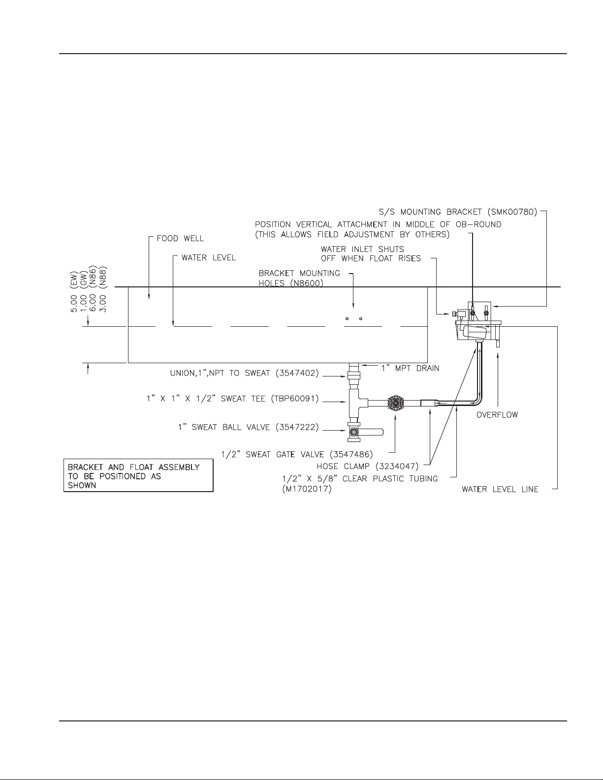
Section 2 Installation
Optional Top-Off Auto Fill Installation
• Option is a loose parts kit. Field installation requires a plumber.
APPLICABLE TO N8600 & N8800 MODELS
1. Locate mounting holes on outside operator drop-in body and mount float and bracket using thumb screws.
2. Install drain plumbing as shown.
3. Connect clear plastic tubing to 1/2” copper stub and connect to the float. Use hose clamps to secure.
4. Connect fill line to 1/4” compression fitting.
5. Loosen thumb screws to achieve desired water level.
NO CONNECTION
NEEDED
Part Number: 9291458C 07/22 33
Page 34
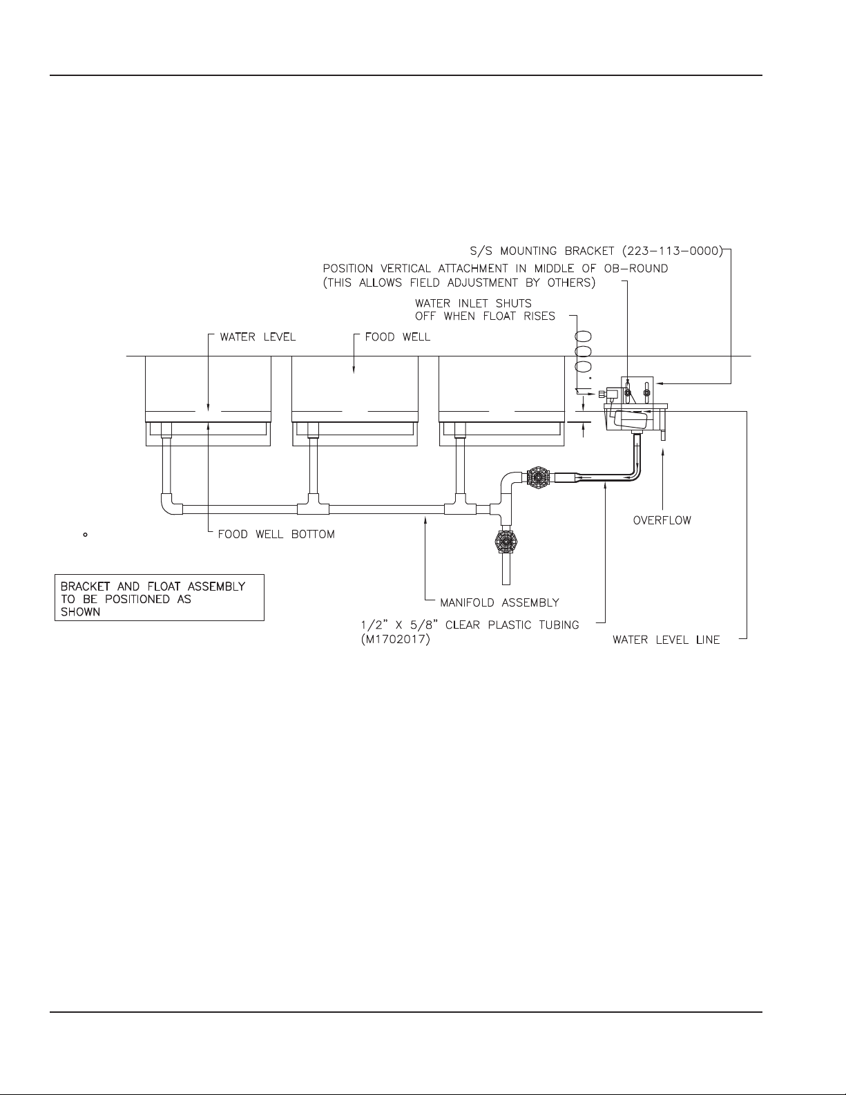
Installation Section 2
APPLICABLE TO N8700 MODELS
1. Locate mounting holes on outside operator drop-in body and mount float and bracket using thumb screws.
2. Install drain plumbing as shown.
3. Connect clear plastic tubing to 1/2” copper stub and connect to the float. Use hose clamps to secure.
4. Connect fill line to 1/4” compression fitting.
5. Loosen thumb screws to achieve desired water level.
NO CONNECTION
NEEDED
34 Part Number: 9291458C 07/22
Page 35

Section 2 Installation
THIS PAGE INTENTIONALLY LEFT BLANK
Part Number: 9291458C 07/22 35
Page 36
Section 3
Operation
DANGER
The on-site supervisor is responsible for ensuring that
operators are made aware of the inherent dangers of
operating this equipment.
DANGER
Do not operate any appliance with a damaged cord
or plug. All repairs must be performed by a qualified
service company.
DANGER
Never stand on the unit! They are not designed to
hold the weight of an adult, and may collapse or tip if
misused in this manner.
Warning
n
Do not contact moving parts.
Warning
n
All covers and access panels must be in place and
properly secured, before operating this equipment.
Warning
n
Damp or wet hands may stick to cold surfaces.
Product Quality in Cold Pans
Warning
n
The operator of this equipment is solely responsible
for ensuring safe holding temperature levels for all
food items. Failure to do so could result in unsafe food
products for customers.
These units are not designed to cool warm food products.
Items should be placed in the unit pre-cooled at least to the
desired holding temperature, if not slightly colder. In some
applications, a gradual warming of product may occur,
particularly at the exposed top of the product. Stirring or
rotation of the product is necessary to maintain overall
temperature.
Warming of food product can occur very quickly outside of
the unit. When loading or rotating product, avoid leaving
food items in a non-refrigerated location for any length of
time to prevent warming or spoilage. To ensure product
quality product must be rotated every four hours.
Note
Drain the water from units daily for unit longevity.
Warning
n
Never use sharp objects or tools to remove ice or frost.
Do not use mechanical devices or other means to
accelerate the defrosting process.
Warning
n
Do not block the supply and return air grills or the air
space around the air grills. Keep plastic wrappings,
paper, labels, etc. from being airborne and lodging in
the grills. Failure to keep the air grills clear will result in
unsatisfactory operation of the system.
Caution
,
Units with pans should be operated with pans in place.
Operating the unit without all pans in place will lower
efficiency and may damage the unit.
36 Part Number: 9291458C 07/22
Page 37
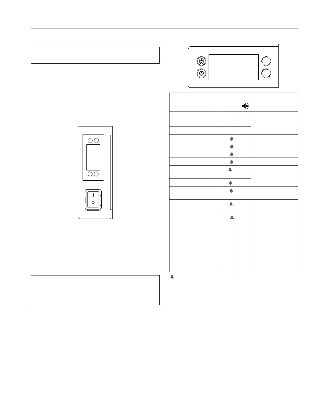
Section 3 Operation
8100-EF(N)P & 8100-FAP Series Operation
Note
The cold pan is not intended to be used with ice.
There is a switch on the compressor housing front to turn
the 8100-EFP units on and off. The unit must be turned off
when not in use or overnight for defrosting and cleaning.
8100-EFP Series LiquiTec® Eutetic fluid cold pans are
adjusted at the factory to provide proper operation without
any further adjustments.
The temperature control is located on the condensing
housing.
Power Switch & Temperature Control
1. At initial start-up or anytime power is disconnected,
then reconnected to the unit, the control will go into
normal cooling mode.
2. The temperature control will cycle the compressor and
condenser fan motor to maintain proper temperature.
Notice
Temperature displayed is for refrigeration set point
purposes only. Display does not reflect air or product
temps in unit.
TEMPERATURE CONTROL & DISPLAY
V
V
Operation / Indication
Status Displayed
Normal (°C) Temp. [°C] Unit depends on setting
Normal (°F) Temp. [°F]
Show set-point Temp.
Sensor 1 defect
Sensor 2 defect
Sensor 3 defect
Sensor 4 defect
High temperature
alarm
Low temperature alarm
Line voltage too high,
above 140 volts
Line voltage too low,
below 96 volts
Control calls for cooling
for more than 24 hours
straight
All alarms sound for approximately 10 seconds and then
E01
E02
E03
E04
Hi
Lo
uHi
uLi
LEA
X Air sensor
X Coil sensor
X Open
X Open
X Automatically switching
X
X
X
X Time includes defrost.
are silent for 50 seconds. It will do that for 15 cycles and
then remain silent. The alarm code will still be present on
the display until the fault clears.
Comments
(parameters in control)
at 2 sec rate
Error will go away if the
control cycles off the
compressor or if the
power is shut off. If error
is on a cold pan it could
be related to a high
ambient temperature or
not shutting the rail off
nightly.
Part Number: 9291458C 07/22 37
Page 38
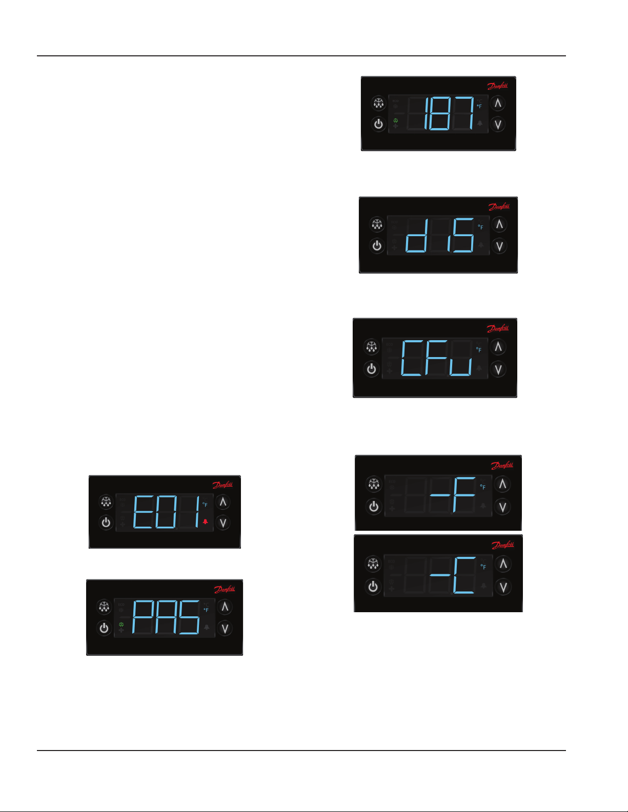
Operation Section 3
Press upper or lower right button.
• Display show actual set-point (blinking).
• If buttons untouched for 3 seconds returns to
normal.
• Increase set-point by pressing upper button. Max value
depends on parameters in control.
• Decrease set-point by pressing lower button. Min value
depends on parameters in control.
• If buttons untouched for 3 seconds returns to
normal and stores new set-point.
Press lower left button for 5 seconds.
• Unit goes into stand-by mode.
• The display will read Off, then a period.
• Press the lower left button again for 5 seconds.
• The display will read On.
• The unit will then start up in normal cooling
mode.
Temperature Alarm
The alarm will sound and flash HI or LO 90 minutes after the
unit has reached its alarm temperature point or after any
power interruption if the temperature is above or below the
alarm set points.
4. Scroll to dis using the up/down arrows and push the
stand-by button (lower left button) to enter into the
display menu.
5. Scroll to CFu using the up/down arrows and push the
stand-by button (lower left button) to enter the display
unit menu.
CHANGING DISPLAY FROM FAHRENHEIT TO CELSIUS
ON ERC112 CONTROL
1. Simultaneously hold the up and down arrows for
5 seconds to access menu for password protected
parameters.
2. Screen should temporarily flash PAS and then move to
a numeric screen.
3. Scroll to 187 using the up/down arrows and push the
stand-by button (lower left button) to enter.
6. -F should be displayed indicating Fahrenheit. Use
the down arrow to change it to -C for Celsius and hit
the stand-by button (lower left button) to enter the
change.
38 Part Number: 9291458C 07/22
Page 39
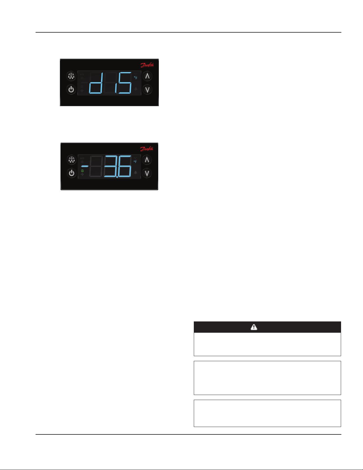
Section 3 Operation
7. Push the defrost button (upper left button) to move
out of the display unit menu.
8. Push the defrost button (upper left button) to move
out of the display menu and back to the normal display.
NOTE: For steps 7 and 8, display will return back to normal
display after 30 seconds of inactivity.
N8100BP, N8100-BRP & N8100NBP Operation
The temperature control is used to turn the unit on and
off as well as control the temperature of the cold pan. The
control is located in the machine compartment. To turn
the cold pan off, press and hold the power button. The
unit must be turned off when not in use or overnight for
defrosting and cleaning.
If the cold pan is to be used with ice, it is recommended
that the optional perforated bottoms be used. These will
allow ice to melt properly.
N8200P & N8200-STP Operation
N8200P and N8200-STP series frost tops are designed
to maintain an even layer of frost to pleasantly display
product. Once turned on, the compressor will run
continuously. There is no temperature control. The ON/OFF
switch is the only means available to cycle the unit.
Since it takes time for the frost to accumulate initially, the
unit should be turned on approximately one hour before it
is required. Product should not be placed on the frost top
prior to turning the unit on, because it may freeze to the
surface of the unit.
The unit must be turned off when not in use or overnight
for defrosting and cleaning.
Operation N8200GP
N8200GP Series granite cold slabs are designed to maintain
a low temperature surface for quick turn products such
as ice cream. Frost patterns will vary depending on room
conditions such as temperature, humidity and airflow. The
work zone of the granite surface is considered to be inside a
2.0” (5.1cm) perimeter. Temperatures in the perimeter zone
may be higher and again the frost patterns in this area will
vary based on room conditions.
Unit is controlled by an on/off switch. Once turned on, the
unit will run continuously. There is no temperature control
in this unit. Turn the unit on approximately two hours prior
to use to allow for ample cool down time. At 75˚F ambient
temperature the unit will reach operating temperature of
0˚F to 20˚F in 2 hours.
The unit must be turned off when not in use or overnight
for defrosting and cleaning.
8600P Hot/Cold Series Operation
Hot Operation
DANGER
When operated at the highest temperature setting, the
top of the unit will become very hot. Staff and customers
using the equipment should be informed about this.
Caution
,
Never use anything other than plain water in the wells
or tank. Failure to observe this warning may result in
personal injury or damage to the unit.
Caution
,
Using ice in a hot food well can cause condensation and
damage to the well over time.
Part Number: 9291458C 07/22 39
Page 40
Operation Section 3
Note
Drain the water from units daily for unit longevity.
N8600P Series hot and cold combination pans must be
operated with water in the well for proper hot operation.
Fill well with a minimum of 4.0” (10.2cm) of water. Place
function switch in HOT position to begin heating. Turn
thermostat dial to the desired temperature.
To turn unit off, simply move the function switch to OFF
position. Drain water and allow unit to cool before cleaning
or switching to cold operation.
Switching From Hot To Cold Operation
1. Place the function switch in the OFF position and drain
out hot water.
2. Allow the unit to cool until it can be safely cleaned.
3. When clean up procedures are complete, unit will be
ready for cold operation. This takes about one hour.
Caution
,
To assure maximum compressor life, do not switch
from “hot” to “cold” operation without allowing a cool
down period. Never switch from hot to cold operation
while hot water remains in the pans. Failure to observe
this warning will greatly reduce compressor life and
eventually cause premature compressor failure.
hot operation. Be certain to fill with a minimum of 4.0” of
water.
Note
The unit is designed so that the compressor and the
heating elements cannot operate at the same time.
Continued operation of the compressor in the hot
position is not normal. Call for service if this happens.
The unit must be turned off when not in use or overnight
for defrosting and cleaning.
N8600P Immersion Heater High Limit
As a safety feature, the N8600P food well immersion heater
includes a high limit safety switch. If the heater gets too
hot the safety switch will trip and turn the heater off. A
pilot light on the control panel will illuminate when the
safety switch is tripped. To reset the safety switch, first turn
OFF the thermostat or Power switch and then determine
if low water is the cause. If low water is not the cause,
contact service for resolution. If low water is the cause,
carefully remove food pans and refill the water. This will
allow the immersion heater to cool and the safety switch
will automatically reset. The unit must be turned OFF
as directed or safety switch will not reset even if water
is refilled to proper level. Replace food pans and turn
thermostat or Power switch back on.
Warning
n
Opening the drain cock will lead to the outflow of the
hot contents of the bains-marie.
Warning
n
Wait for the water to cool to at minimum 140°F before
opening the drain cock.
Warning
n
It is not advised or acceptable to use the refrigeration
system to cool the hot water. It is also not advised to run
the refrigeration system with any water in the unit.
Cold Operation
Simply place the function switch to the COLD position.
The compressor controller has been factory set and no
temperature adjustment should be necessary.
If the cold pan is to be used with ice, it is recommended
that the optional perforated bottoms be used. These will
allow ice to melt properly.
Switching From Cold To Hot Operation
No special procedure is required to switch from the cold to
40 Part Number: 9291458C 07/22
Page 41
Section 3 Operation
N8700-D, N8700N, N8700-R & N8800 Series
Operation
These units are designed to hold warm food product
between 140°F to 160°F (60°C to 71 °C).
N8700-D, N8700N and N8700-R series individually heated
hot food units may be operated wet (with water in the
wells) or dry. Wet operation is recommended for better
performance.
N8800 Series single tank hot food units are designed to be
operated wet (with water in the tank) only.
Note
Proper water level is approximately 2.0” (5.1cm). It must
be maintained to prevent damage to the tank on the
N8800 Series units.
After the unit is hard wired to the electrical system, select
desired temperature by rotating temperature control. A
knob and indicator light are provided for each individual
heated food well.
First Time Use
Before the unit is used the first time for serving, turn the
temperature knob to HI and heat the well for 20 to 30
minutes.
Any residue or dust that adhered to the heater element(s)
will be burned off during this initial preheat period.
When serving thick sauces always use the hot food well in
wet operation. This provides more uniform temperature for
the sauce.
Note
Never place food directly in well. Always use pans.
For most efficient operation, keep covered inserts in each
well during preheating or when empty.
Always place covers on pans when not serving to prevent
food from drying out.
Wet Operation
DANGER
When operated at the highest temperature setting, the
top of the unit will become very hot. Staff and customers
using the equipment should be informed about this.
DANGER
Steam can cause serious burns. Always use some type
of protective covering on your hands and arms when
removing lids from the unit. Lift the lid in a way that will
direct escaping steam away from your face and body.
Caution
,
Wipe wells clean of debris and metal shavings before
operation. Debris left in the well may cause rust or
damage to the protective stainless steel layer.
Caution
,
Never use anything other than plain water in the wells
or tank. Failure to observe this warning may result in
personal injury or damage to the unit.
Caution
,
Using ice in a hot food well can cause condensation and
damage to the well over time.
Note
Drain the water from units daily for unit longevity.
Fill the food well with a minimum of 2.0” (5.1cm) of water
and cover with lid or empty pan. To preheat water, set
temperature control at HI. With pans in place, wells will boil
water. Food temperature will vary depending on type and
amount of product. To minimize steam and water usage,
set control at lowest setting that will maintain proper food
temperature. To reduce preheating time, use hot water to
fill the well.
Warning
n
Opening the drain cock will lead to the outflow of the
hot contents of the bains-marie.
Dry Operation N8700 Series only
DANGER
When operated dry, the well bottoms become very
hot. Do not allow unprotected skin to contact any well
surface.
Wet operation is usually much more efficient and is
preferred. However, these units may be operated without
water with no damage to the unit.
When operated dry, the bottom of the well will discolor. To
clean, use a stainless steel cleaner or mild abrasive.
N8700-DESP Operation
These units are designed to hold warm food product
between 140°F to 160°F (60°C to 71°C).
N8700-DESP series individually heated hot food units may
be operated wet (with water in the wells) or dry. However,
dry operation using 6.0” deep pans produces optimum
performance.
Part Number: 9291458C 07/22 41
Page 42
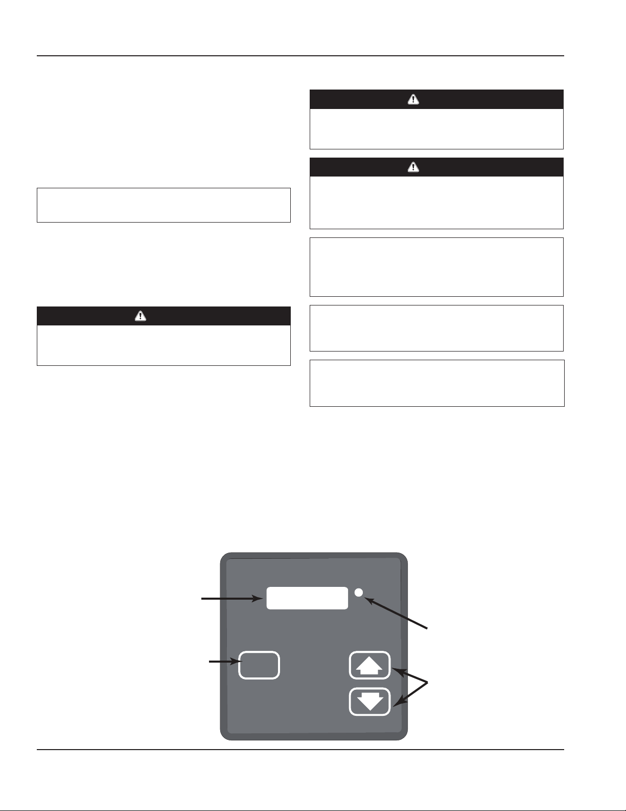
Operation Section 3
A power switch and digital control are provided for each
individual heated food well. After the unit is hard wired to
the electrical system, turn the power switch ON to energize
the control; the digital display will read OFF. Press Set and
then use the arrows to select the desired temperature
setting (1-10). The new temperature setting is entered 3
seconds after the last button is pressed. When the power
switch is used to turn the well OFF and back ON the
temperature setting will remain.
Note
Never place food directly in well. Always use pans.
For most efficient operation, keep covered inserts in each
well during preheating or when empty.
Always place covers on pans when not serving to prevent
food from drying out.
Dry Operation
DANGER
When operated dry, the well bottoms become very
hot. Do not allow unprotected skin to contact any well
surface.
Dry operation is more efficient and is preferred.
When operated dry, the bottom of the well will discolor. To
clean, use a stainless steel cleaner or mild abrasive.
Wet Operation
DANGER
When operated at the highest temperature setting, the
top of the unit will become very hot. Staff and customers
using the equipment should be informed about this.
DANGER
Steam can cause serious burns. Always use some type
of protective covering on your hands and arms when
removing lids from the unit. Lift the lid in a way that will
direct escaping steam away from your face and body.
Caution
,
Never use anything other than plain water in the wells
or tank. Failure to observe this warning may result in
personal injury or damage to the unit.
Caution
,
Using ice in a hot food well can cause condensation and
damage to the well over time.
Warning
n
Opening the drain cock will lead to the outflow of the
hot contents of the bains-marie.
Fill the food well with a minimum of 2” (5cm) of water
and cover with lid or empty pan. To preheat water, set
temperature control at 3. With pans in place, wells will boil
water. Food temperature will vary depending on type and
amount of product. To minimize steam and water usage,
set control at lowest setting that will maintain proper food
temperature. To reduce preheating time, use hot water to
fill the well. Preheating time with room temperature water
is one hour.
N8700-DESP Temperature Control Operation
LED Display: Indicates the
temperature setting 0-10. At the first
startup the display will read OFF.
SET: When SET is depressed, the
temperature setting is displayed and
can be adjusted with the arrows.
SET
LOAD
LOAD Light: Lit when well is heating.
Arrows: After pressing SET, press the
Up-Arrow to increase the temperature
setting, press the Down-Arrow to
decrease the temperature setting. The
new temperature setting is entered 3
seconds after the last arrow is pressed.
42 Part Number: 9291458C 07/22
Page 43
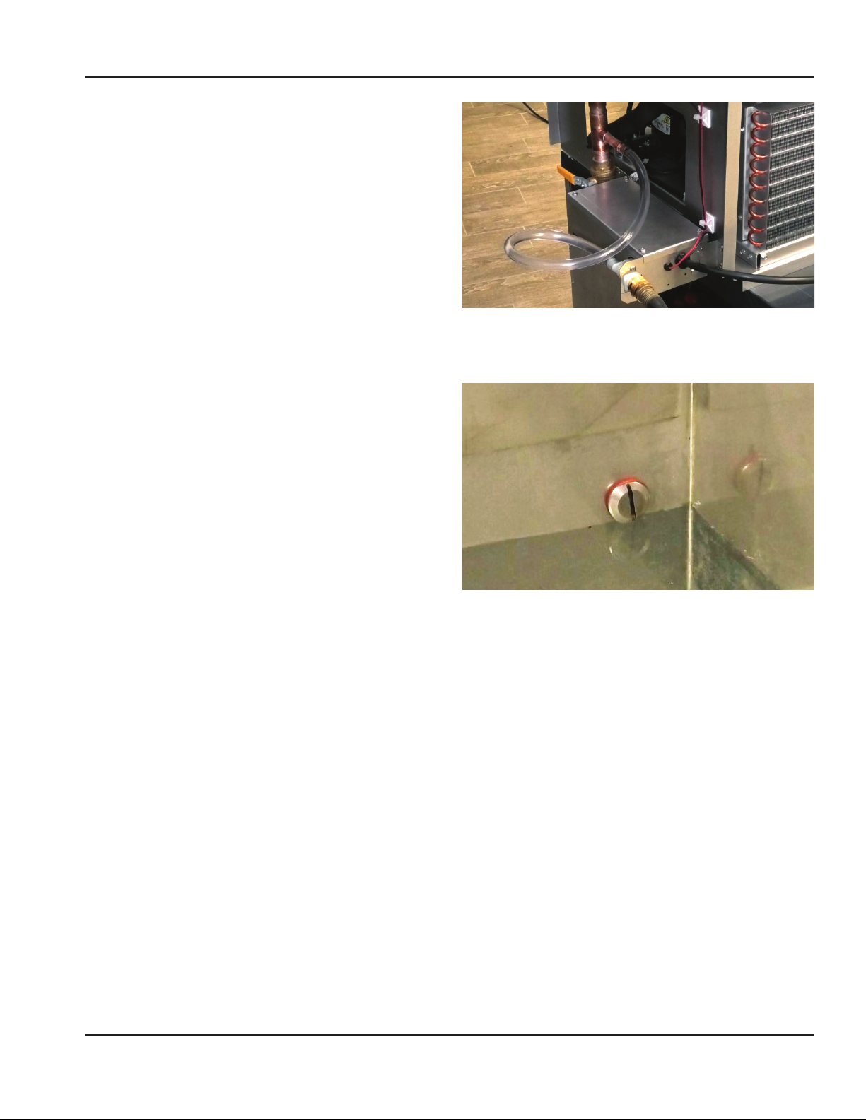
Section 3 Operation
ELECTRONIC HIGHVOLUME AUTO FILL OPTION
Wet operation units can be manufactured with an optional
high-volume auto fill feature. The high-volume auto fill
feature is installed with a regular garden hose and the units
power. The remote lighted on/off switch will operate the
water flow and allow the sensors within the well to dictate
when the high-volume auto fill will need to add water into
the well after normal evaporation occurs. These highvolume auto fills must be installed in the factory and cannot
be installed in the field.
Electronic High-Volume Auto Fill Operation
Close the drain valve to the well. Turn the on/off switch to
the on position. A 30-60 second delay will occur before the
unit will begin water flow up from the drain. Once the water
flow reaches the sensor, the unit will stop flow of water. YOU
DO NOT NEED TO TURN THE SWITCH OFF. Heated water will
evaporate and eventually lower the water level below the
sensor. A 30-60 second delay will occur and then the highvolume auto fill will begin to fill the well up to the sensor.
At the end of the night/shift turn the high-volume auto fill
switch to the off position and drain the well with the drain
valve under the well and clean the unit once cool enough
to touch.
Electronic High-Volume Auto Fill Cleaning
Sensors must be free of build-up and calcium deposits.
Failure to do so may result in overflow and/or malfunction.
Sensors should be cleaned regularly and wells daily.
Part Number: 9291458C 07/22 43
Page 44

Operation Section 3
THIS PAGE INTENTIONALLY LEFT BLANK
44 Part Number: 9291458C 07/22
Page 45
Section 4
Maintenance
DANGER
It is the responsibility of the equipment owner to
perform a personal protective equipment hazard
assessment to ensure adequate protection during
maintenance procedures.
DANGER
Failure to disconnect the power at the main power
supply disconnect could result in serious injury or death.
The power switch DOES NOT disconnect all incoming
power.
DANGER
Disconnect electric power at the main power disconnect
for all equipment being serviced. Observe correct
polarity of incoming line voltage. Incorrect polarity can
lead to erratic operation.
Warning
n
Never use sharp objects or tools to remove ice or frost.
Do not use mechanical devices or other means to
accelerate the defrosting process.
Cleaning and Sanitizing Procedures
Caution
,
Maintenance and servicing work other than cleaning as
described in this manual must be done by an authorized
service personnel.
GENERAL
Warning
n
When using cleaning fluids or chemicals, rubber gloves
and eye protection (and/or face shield) must be worn.
You are responsible for maintaining the equipment
in accordance with the instructions in this manual.
Maintenance procedures are not covered by the warranty.
Maintenance Daily Weekly Monthly
Exterior X X X
Gasket X X X
N8100-FAP Series
Drain
Condenser Coil X X X
Part Number: 9291458C 07/22 45
X X X
After Prolonged
Shutdown
At Start-Up
Page 46
Maintenance Section 4
EXTERIOR CLEANING
Warning
n
When cleaning the unit, care should be taken to avoid
the front power switch and the rear power cord. Keep
water and/or cleaning solutions away from these parts.
Warning
n
Never use a high-pressure water jet for cleaning or
hose down or flood the units with water. Do not use
power cleaning equipment, steel wool, scrapers or wire
brushes on stainless steel or painted surfaces.
Caution
,
Never use an acid based cleaning solution, including a
delimer! Acid will deteriorate the finish and damage the
heating element. Food products can also be acidic, keep
equipment clean of ALL food products.
Clean the area around the unit as often as necessary to
maintain cleanliness and efficient operation.
Gaskets require daily cleaning to prevent mold and
mildew build up and also to retain the elasticity of the
gasket. Gasket cleaning can be done with the use of warm
soapy water (no citrus based cleaners). Avoid full strength
cleaning products on gaskets as this can cause them to
become brittle and crack. Never use sharp tools or knives to
scrape or clean the gasket.
Wipe surfaces with a damp cloth rinsed in water to remove
dust and dirt from the unit. Always rub with the “grain” of
the stainless steel to avoid marring the finish. If a greasy
residue persists, use a damp cloth rinsed in a mild dish soap
and water solution. Wipe dry with a clean, soft cloth.
Never use steel wool or abrasive pads for cleaning. Never
use chlorinated, citrus based or abrasive cleaners.
Stainless steel has a clear coating that is stain resistant and
easy to clean. Products containing abrasives will damage
the coating and scratch the panels. Daily cleaning may be
followed by an application of stainless steel cleaner which
will eliminate water spotting and fingerprints. Early signs of
stainless steel breakdown are small pits and cracks. If this
has begun, clean thoroughly and start to apply stainless
steel cleaners in attempt to restore the steel.
N8600P Immersion Heater
Follow the same as instructions as the rest of the food well:
Wipe surfaces with a damp cloth rinsed in water to remove
dust and dirt from the unit. If a greasy residue persists, use
a damp cloth rinsed in a mild dish soap and water solution.
Wipe dry with a clean, soft cloth. Never use steel wool or
abrasive pads for cleaning. Never use chlorinated, citrus
based or abrasive cleaners.
Defrosting
Refrigerated cold pans MUST be defrosted daily. Never
use sharp objects or tools to clean or scrape ice/frost build
up from the refrigerated cold pans. A puncture to the pan
could cause irreparable damage to the refrigeration system.
Units with a Eutectic Fluid Cold Pan require the same
precautions. The fluid is NOT refillable and loss of fluid due
to a puncture would cause irreparable damage.
CLEANING THE CONDENSER COIL
In order to maintain proper refrigeration performance, the
condenser fins must be cleaned of dust, dirt and grease
regularly. It is recommended that this be done monthly. If
conditions are such that the condenser is totally blocked
in a month, the frequency of cleaning should be increased.
Clean the condenser with a vacuum cleaner or stiff brush. If
extremely dirty, a commercially available condenser cleaner
may be required.
Failure to maintain a clean condenser coil can initially cause
high temperatures and excessive run times. Continuous
operation with a dirty or clogged condenser coil can
result in compressor failure. Neglecting the condenser coil
cleaning procedures will void any warranties associated
with the compressor and cost to replace the compressor.
N8100FAP SERIES DRAIN MAINTENANCE
Each N8100-FA unit has a drain located inside the unit that
removes the condensation from the evaporator coil and
routes it to an external condensate evaporator pan. Each
drain can become loose or disconnected during normal use.
If you notice water accumulation under the unit, be sure the
drain tube is connected to the evaporator drain pan and the
end of the drain tube is in the condensate evaporator. The
leveling of the unit is important as the units are designed to
drain properly when level. Be sure all drain lines are free of
obstructions.
46 Part Number: 9291458C 07/22
Page 47

Section 4 Maintenance
THIS PAGE INTENTIONALLY LEFT BLANK
Part Number: 9291458C 07/22 47
Page 48
DELFIELD
980 SOUTH ISABELLA ROAD, MOUNT PLEASANT, MI 48858
800-733-8821
WWW.DELFIELD.COM
Import:
Germany
Welbilt Deutschland
Auf der Weih 11
35745 Herborn
Germany
+49 2772 58050
Import:
United Kingdon
Welbilt UK Limited
Provincial Park, Nether Lane
Ecclesfield
Sheffield, S35 9ZX
United Kingdom
+44 1483 464900
©2019 Welbilt Inc. except where explicitly stated otherwise. All rights reserved.
Part Number 9291458C 07/22
 Loading...