

Page 1
Shelleymatic
®
by Deleld
Milk, Ice Cream and Milk & Ice Cream Dispensers
Service and Installation Manual
Please read this manual completely before attempting to install or operate this equipment! Notify carrier of damage! Inspect all
components immediately. See page 2.
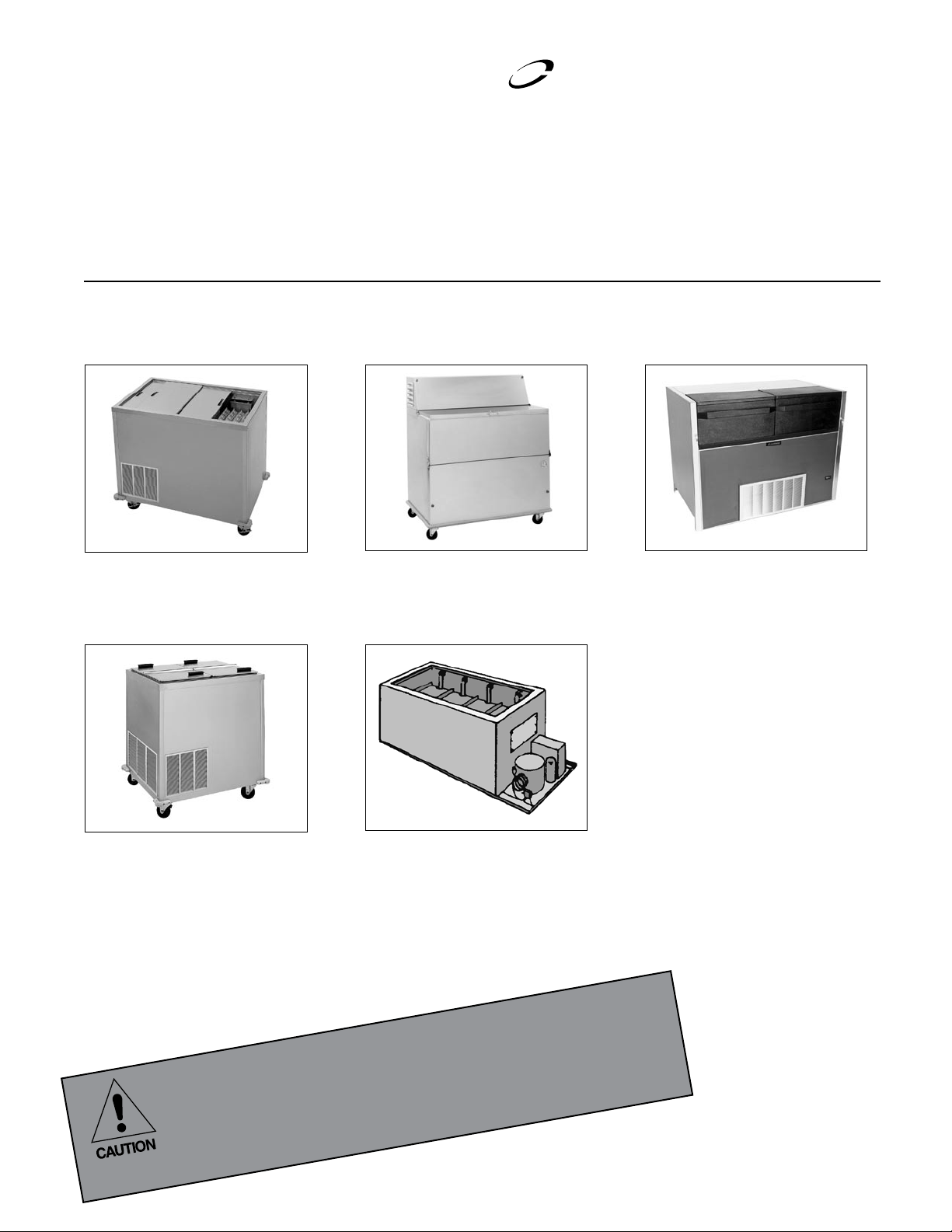
N, N6/N10/N14
Free-standing milk or
beverage dispensers
NSCF, SCF
Free-standing ice cream
dispensers and milk & ice
cream dispensers
NDF
Free-standing milk or
beverage dispensers
MF, MFSC, FF,
FFSC, RFF, RFFSC
Built-in milk or beverage,
ice cream, and milk & ice cream
dispensers
NLFAC
Free-standing milk or beverage
dispensers with air curtain
IMPORTANT INFORMATION
PLEASE SAVE THESE INSTRUCTIONS!
READ BEFORE USE
August 2010
Page 2

Milk, Ice Cream & Milk & Ice Cream Dispensers Service and Installation Manual
Contents
Serial Number Location .............................................................2
Receiving and Inspecting Equipment ........................................2
Specifications .............................................................................3
Installation ...............................................................................4-5
Operation ....................................................................................6
Maintenance ...............................................................................7
Wiring Diagram ..........................................................................8
Replacement Parts ................................................................9-16
Standard Labor Guidelines ......................................................17
Standard Warranties ...........................................................18-19
©2010 The Delfield Company. All rights reserved. Reproduction without
written permission is prohibited. “Delfield” and “Shelleymatic” are registered
trademarks of The Delfield Company.
Serial Number Location
Serial number tag locations
MF/MFSC, FF/FFSC and RFF/RFFSC — on the end above the
refrigeration system.
N, N6/N10/N14, and SCF — rear of the unit above the louver.
NDF — Front right hand corner under the lid.
NLFAC — at the rear of the unit by the power cord.
Always have the serial number of your unit available when calling
for parts or service. A complete list of authorized Delfield parts
depots is available at www.delfield.com.
The units represented in this manual are for indoor use only.
Receiving and Inspecting the Equipment
Even though most equipment is shipped crated, care should
be taken during unloading so the equipment is not damaged
while being moved into the building.
1. Visually inspect the exterior of the package and skid or
container. Any damage should be noted and reported to
the delivering carrier immediately.
2. If damaged, open and inspect the contents with the
carrier.
3. In the event that the exterior is not damaged, yet upon
opening, there is concealed damage to the equipment
notify the carrier. Notification should be made verbally
as well as in written form.
4. Request an inspection by the shipping company of the
damaged equipment. This should be done within 10
days from receipt of the equipment.
5. Check the lower portion of the unit to be sure casters are
not bent.
6. Also open the compressor compartment housing and
7. Freight carriers can supply the necessary damage forms
8. Retain all crating material until an inspection has been
Uncrating the Equipment
First cut and remove the banding from around the crate.
Remove the front of the crate material, use of some tools will
be required. If the unit is on legs remove the top of the crate
as well and lift the unit off the skid. If the unit is on casters it
can be rolled off the skid.
visually inspect the refrigeration package. Be sure lines
are secure and base is still intact.
upon request.
made or waived.
2
For customer service, call (800) 733-8829, (800) 773-8821, Fax (989) 773-3210, www.delfield.com
Page 3
Milk, Ice Cream & Milk & Ice Cream Dispensers Service and Installation Manual
Specifications
Model H.P. Loading/Dispensing Length Depth Height Weight (lbs) Amps (115V) NEMA Plug BTU Load Evap BTU/TD BTU Capacity Ref/Charge
Self-contained free-standing milk or beverage dispensers
N-520
N-860
N-1200
N-1530
N6-1313-34
N6-1313-36
N10-1313-34
N10-1313-36
N14-1313-34
N14-1313-36
Self-contained free-standing milk or beverage dispensers
NDF-12
NDF-18
Self-contained free-standing milk or beverage dispensers with air curtain (BTU is with lids closed.)
NLFAC-8
NLFAC-12
NLFAC-16
Self-contained free-standing milk and ice cream dispensers
NSCF-48
Self-contained free-standing ice cream dispensers
SCF-32
SCF-48
Model H.P. Cutout Dim. (L x D) L x D x H Weight (lbs) Amps (115V) NEMA Plug BTU Load Evap BTU/TD BTU Capacity Ref/Charge
Self-contained built-in milk or beverage dispensers *a 2.87” space is required between each cutout
MFSC-2020
MFSC-2821
MFSC-31
MFSC-44
MFSC-57
Remote built-in milk or beverage dispensers *a 2.87” space is required between each cutout
MF-2020
MF-2821
MF-31
MF-44
MF-57
Remote built-in ice cream dispensers *a 2.87” space is required between each cutout
FF-3324
FF-2
Self-contained built-in ice cream dispensers *a 2.87” space is required between each cutout
FFSC-3324
FFSC-2
Self-contained built-in milk & ice cream dispensers *a 2.87” space is required between each cutout
RFFSC-103
Remote built-in milk & ice cream dispensers *a 2.87” space is required between each cutout
RFF-103
1/4 sliding top lids 29” x 28” x 36” 327 5.0 5-15P 189 33/31º 1035 134a/16oz
1/4 sliding top lids 42” x 28” x 36” 392 5.0 5-15P 259 42/28º 1167 134a/16oz
1/4 sliding top lids 55” x 28” x 36” 462 5.0 5-15P 328 51/25º 1273 134a/16oz
1/4 sliding top lids 68” x 28” x 36” 532 5.0 5-15P 398 60/23º 1360 134a/16oz
1/4 sliding top lids 36” x 32” x 34” 382 5.0 5-15P 245 42/28º 1167 134a/16oz
1/4 sliding top lids 36” x 32” x 36” 402 5.0 5-15P 245 42/28º 1167 134a/16oz
1/4 sliding top lids 54.5” x 32” x 34” 545 5.0 5-15P 353 55/24º 1315 134a/16oz
1/4 sliding top lids 54.5” x 32” x 36” 565 5.0 5-15P 353 55/24º 1315 134a/16oz
1/4 sliding top lids 73” x 32” x 34” 650 5.0 5-15P 455 68/21º 1422 134a/16oz
1/4 sliding top lids 73” x 32” x 36” 670 5.0 5-15P 455 68/21º 1422 134a/16oz
1/4 drop front & flip top lids 35.88” x 33.38” x 57” 365 5.0 5-15P 687 49/25º 1204 134a/16oz
1/3 drop front & flip top lids 49.88” x 33.38” x 57” 430 7.0 5-15P 898 60/27º 1585 134a/24oz
1/3 hinged lids w/air curtain 40” x 32” x 42.50” 401 7.0 5-15P 668 140/16º 2184 134a/24oz
1/2 hinged lids w/air curtain 54” x 32” x 42.50” 491 9.0 5-15P 859 140/21º 2885 134a/32oz
1/2 hinged lids w/air curtain 68” x 32” x 42.50” 583 11.0 5-15P 1050 140/23º 3193 134a/32oz
1/4 hinged top lids 48” x 28” x 37” 390 7.1 5-15P 139(ref)
1/4 hinged top lids 32.5” x 28” x 37” 334 7.1 5-15P 709 51/18º 915 404A/16oz
1/3 hinged top lids 48” x 28” x 37” 414 8.0 5-15P 1043 69/19º 1350 404A/24oz
1/4 (1) 25.25” x 22.25” 43.25” x 26.25” x 28.25” 303 5.0 5-15P 304 51/24º 1223 134a/16oz
1/4 (1) 10.75” x 21” 28.5” x 26.25” x 28.25” 267 5.0 5-15P 264 45/26º 1166 134a/16oz
1/4 (2) 10.75” x 21”* 42” x 26.25” x 28.25” 306 5.0 5-15P 296 50/24º 1212 134a/16oz
1/4 (3) 10.75” x 21”* 55.5” x 26.25” x 28.25” 413 5.0 5-15P 408 64/21º 1346 134a/16oz
1/4 (4) 10.75” x 21”* 69” x 26.25” x 28.25” 461 5.0 5-15P 519 79/18º 1447 134a/16oz
N/A (1) 25.25” x 22.25” 29.25” x 26.25” x 28.25” 240 N/A N/A 304 51/24º N/A 134a/N/A
N/A (1) 10.75” x 21” 14.5” x 26.25” x 28.25” 197 N/A N/A 264 45/26º N/A 134a/N/A
N/A (2)10.75” x 21”* 28” x 26.25” x 28.25” 238 N/A N/A 296 50/24º N/A 134a/N/A
N/A (3)10.75” x 21”* 41.5” x 26.25” x 28.25” 312 N/A N/A 408 64/21º N/A 134a/N/A
N/A (4) 10.75” x 21”* 55” x 26.25” x 28.25” 335 N/A N/A 519 79/18º N/A 134a/N/A
N/A (1) 10.75” x 21” 14.5” x 26.25” x 28” 215 N/A N/A 434 35/22º N/A 404A/N/A
N/A (2)10.75” x 21”* 28” x 26.25” x 28” 290 N/A N/A 709 51/18º N/A 404A/N/A
1/4 (1) 10.75” x 21” 28.5” x 26.25” x 28.25” 308 7.1 5-15P 434 35/22º 763 404A/16oz
1/3 (2) 10.75” x 21”* 42” x 26.25” x 28.25” 408 8.0 5-15P 709 51/18º 915 404A/24oz
1/4 (2) 10.75” x 21”* 42” x 26.25” x 28.25” 428 7.1 5-15P 139(ref)
N/A (2) 10.75” x 21” 28” x 26.25” x 28” 310 N/A N/A 139(ref)
414(frz)
414(frz)
414(frz)
37/43º(ref)
37/21º(frz)
37/43º(ref)
37/21º(frz)
37/43º(ref)
37/21º(frz)
1596(ref)
796(frz)
1596 (ref)
796(frz)
N/A 404A/N/A
404A/16oz
404A/16oz
404A/16oz
For customer service, call (800) 733-8829, (800) 773-8821, Fax (989) 773-3210, www.delfield.com
3
Page 4
Milk, Ice Cream & Milk & Ice Cream Dispensers Service and Installation Manual
Installation
Location
These units are intended for indoor use only. Be sure the location
chosen has a floor strong enough to support the total weight of
the cabinet and contents. Units in this product line can weigh as
much as 1500 pounds when it is fully stocked. Reinforce the
floor as necessary to provide for maximum loading.
For the most efficient refrigeration, be sure to provide good air
circulation inside and out.
Inside cabinet: Do not pack unit so full that air cannot circulate.
Take care not to block air flow to the fans and allow space along
sides.
Outside cabinet: Be sure that the unit has access to ample
air. Avoid hot corners and locations near stoves and ovens. It
is recommended that the rear of the unit be no less than two
inches from any wall, partition or any other object which will
restrict exhaust air flow.
Leveling
A level cabinet looks better and will perform better because
the cabinet will not be subject to unnecessary strain due to
doors not properly lining up with door frames.
Some models have casters for ease of cleaning underneath and
for mobility. It is important that the unit be installed in a stable
condition with the front casters locked before operating. Locking
the front casters after installation is the operator’s responsibility.
Electrical connection
A standard self-contained unit is provided with a power cord
and three-prong grounded plug.
The unit should be plugged into a receptacle with its own
circuit protection that matches the amperage of the plug.
Refer to the amperage data on page three or the
serial tag data and your local code or the National
Electrical Code to be sure the unit is connected
to the proper power source. A protected circuit of
the correct voltage and amperage must be run for
connection to the unit.
The power supply must be disconnected
whenever performing maintenance or repairing
the equipment!
Built-in units
All self-contained units (MFSC, FFSC and RFFSC) are tested at
the factory to assure proper operation. The unit should not be
installed directly next to high heat generating equipment (ranges,
griddles, etc.).
These units are built into the counter from below and must be
supported from the bottom. The counter cut-out sizes and power
supply requirements are shown in the specifications on page
three. All refrigerators have drains located in the bottom of the
tank. An appropriate drainage area or container must be provided
by the customer. Be sure to place the unit so the pressure control,
located near the compressor, can be reached.
For installation of remote units (MF, FF and RFF), consult a
refrigeration service company to connect refrigeration lines to the
remote condensing unit.
Self-contained refrigerated units (MFSC, FFSC and
RFFSC) require air flow to the compressor. A louver
is provided and must be installed in the counter in
front of the condenser. An equal size opening at the
rear of the cabinet must also be provided to allow
warm air to escape. Failure to do so will void all
product warranties.
Free standing units
All self-contained units (N, N6/10/14, NDF, NLFAC, SCF and
NSCF) are tested at the factory to assure proper operation. The
unit should not be installed directly next to high heat generating
equipment (ranges, griddles, etc.).
These units are free standing, either on legs or casters. The
power supply requirements are shown on page three. All free
standing units have drains located in the bottom of the tank.
An appropriate drainage area or container must be provided by
the customer.
Do not place the unit against a wall or any object that will block
air circulation through the condensing unit. If the unit must
be placed against a wall, leave a minimum of 2” of space for
air flow.
The unit must never be operated without the
louvered panel in place.
4
For customer service, call (800) 733-8829, (800) 773-8821, Fax (989) 773-3210, www.delfield.com
Page 5

Milk, Ice Cream & Milk & Ice Cream Dispensers Service and Installation Manual
RETAINER
LOAD TRAY
ELEVATOR HOUSINGS
RETAINER
REMOVE SCREWS,
SLIDE COVER OFF
REMOVE OR
ADD SPRINGS
AS NEEDED
Installation Continued
How to adjust self-leveling dispenser
Tools Needed: One small flat head screw driver; One Phillips
head screw driver.
1. Always wear safety glasses when adjusting your dispenser.
Also, lock brakes on mobile units before beginning.
2. Unload dispenser and remove stainless steel load tray by
lifting straight up and set it aside (see figure 1).
(Figure 1) Sample unit
3. Use small regular screw driver to loosen each retainer
mounted on stainless steel rod at top of each elevator
housing.
4. To remove elevator
housing, lift
housing straight
up to clear the
stud on unit base.
Then gently swing
the bottom of the
housing towards
the inside of the
unit and pull
housing out of the
unit (see figure 2).
Lay housing on
flat surface.
5. Use Phillips head
screw driver to
remove front panel
on the elevator
housing (see figure
3).
6. If carrier is riding
too high, you need
to remove springs.
With carrier all the
way to the top, gently
disengage one spring
at a time, unhooking
(Figure 3) Remove front panel
bottom loop out of
carrier bracket (see
figure 4). Remove
as many springs as
necessary.
If carrier is riding too
low, you need to add
springs. With carrier
all the way to the top,
gently engage one
spring at a time by
hooking bottom loop
of spring into carrier
bracket. Add as many
(Figure 4) Remove or add springs
springs as necessary.
7. When finished, put elevator housing back in unit and put
stainless steel load tray back on elevator housings. Load
unit to test dispensing level. If spring adjustment does
not position carrier properly, repeat procedure #6 trying
different springs. If this does not work, a different set
of springs may be required. To order, call The Delfield
Company Parts and Service Department at 800.733.8829
8. If level is appropriate, put front panels back on and
tighten retainer.
CAUTION: Dispenser should not be operated
with front panels off elevator housing.
When adjusting the elevators make sure each have the
NOTE:
same number and size of springs connected to the carrier on
both sides. This will prevent the load tray from binding.
(Figure 2) Remove elevator housing
For customer service, call (800) 733-8829, (800) 773-8821, Fax (989) 773-3210, www.delfield.com
5
Page 6
Milk, Ice Cream & Milk & Ice Cream Dispensers Service and Installation Manual
Operation: N, N6/10/14, NDF, NLFAC, MF & MFSC Series
N, N6/10/14, NDF, NLFAC and MFSC Series milk dispensers
are set at the factory to maintain temperatures between 36°F
and 40°F. No further adjustment should be necessary. To begin
operation on self-contained models, plug the electrical supply
cord into a receptacle with the correct voltage. Remote models
will require a connection to a separate refrigeration system.
Loading: N, MF & MFSC Series
To load, place a complete layer of cartons or bottles standing
upright on the load tray. Then place a divider tray on top of
this layer, then another layer of cartons or bottles on this tray,
then another tray and another layer, etc. As each additional
tray is loaded, the elevators gradually lower. The last layer
may be placed on top without the use of another tray. When
loading the average tall half pint bottles, four layers may be
loaded into each compartment standing upright and the fifth
layer laying down.
It is very important to use the divider trays
provided between each successive layer of
contents to assure the correct balance of the
load and the proper action of the elevating
mechanism.
Wire racks, when used, should be loaded completely. When
placing one rack on top of the other, be sure the stacking lugs
are properly aligned.
Loading: N6/10/14 Series
These cabinets are designed to dispense 13” x 13” x 11” high
(maximum dimensions) dairy cases. Place one case loaded
with milk on the carrier and then place a second case loaded
with milk on top of the first case. Press down on the cases
leaning them toward the retaining bracket located under the
top lid track, then gradually release pressure on the cases
so that the top edge of the case engages with the retaining
bracket.
The elevating mechanism is designed to keep the contents
several inches below the top of the cabinet when fully loaded.
This distance serves two purposes:
A. It keeps the top layer of milk completely refrigerated even
when the lids are removed.
B. It insures that the lids will operate without striking the
contents as successive layers are added.
Loading: NDF Series
These cabinets are designed to dispense 13” x 13” x 11” high
(maximum dimensions) dairy cases. They do not have a selfleveling mechanism. Simply place the cases on top of each
other inside the cabinet through the wide opening in the top
and front.
Loading: NLFAC Series
These cabinets are designed to dispense 13” x 13” x 11” high
(maximum dimensions) dairy cases. Model NLFAC-8 holds
eight cases; four on the bottom and four on the top. Model
NLFAC-12 holds twelve cases; six on the bottom and six on
the top. Model NLFAC-16 holds sixteen cases, eight on the
bottom and eight on the top.
Milk cases are loaded through the wide opening in the top and
front of the unit. Fold the hinged lids up and back and rest
them on the top. The cabinet interior has self-locating guides
installed to make loading easy.
Operation: FFSC, RFFSC, SCF & NSCF series
FFSC and SCF Series ice cream dispensers are set at the
factory to maintain temperatures between -5°F and 0°F. RFFSC
and NSCF Series combination milk and ice cream dispensers
are set at the factory to maintain temperatures between 36°F
and 40°F for refrigerated product and between -5°F and 0°F for
frozen product. Each combination unit is constructed with two
tanks and separate controls. No further adjustments should be
necessary. To begin operation plug the electrical supply cord
into a receptacle with the correct voltage.
Loading
To load, place two layers of ice cream on the load tray, then a
tray, two additional layers of ice cream, then another tray, etc.
Do not stack ice cream above the frost line on the interior of
the freezer. See the instructions for the MF units (above) for
loading the refrigerated portion of the combination units.
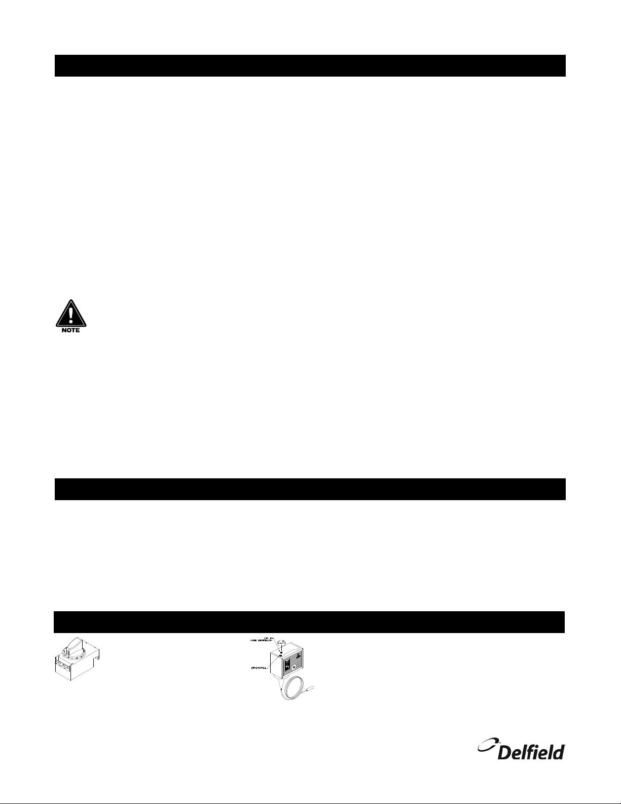
Temperature Control
NLFAC Thermostat Control
Set the thermostat toward 1 for
higher temperatures and toward
7 for lower temperatures. The
refrigerator factory setting is 4
and maintains 38ºF (3ºC) in the
box.
6
For customer service, call (800) 733-8829, (800) 773-8821, Fax (989) 773-3210, www.delfield.com
Low Pressure Control, Remaining Self Contained Models
If it is necessary to adjust the temperature, turn the knob
clockwise as indicated on the control. Make adjustments
gradually. It may take an hour to realize the temperature
change. Milk or beverage dispenser factory settings are 17ºF
differential, 34ºF cut in, and 17ºF cut out. Milk and ice cream
dispenser factory settings are 25ºF differential, 30ºF cut in, and
5ºF cut out.
Page 7

Milk, Ice Cream & Milk & Ice Cream Dispensers Service and Installation Manual
Maintenance
Door Gasket Maintenance
Door gaskets require regular cleaning to prevent mold and mildew build up
and also to retain the elasticity of the gasket. Gasket cleaning can be done
with the use of warm soapy water. Avoid full strength cleaning products
on gaskets as this can cause them to become brittle and crack. Never
use sharp tools or knives to scrape or clean the gasket. Gaskets can be
easily replaced and do not require the use of tools or an authorized service
person. The gaskets are “Dart” style and can be pulled out of the groove in
the door and new gaskets can be “pressed” back into place.
Drain Maintenance - Base
Each unit has a drain located inside the unit that removes the condensation
from the evaporator coil and routes it to an external condensate evaporator
pan. Each drain can become loose or disconnected during normal use.
If you notice water accumulation on the inside of the unit be sure the
drain tube is connected to the evaporator drain pan. If water is collecting
underneath the unit make sure the end of the drain tube is in the
condensate evaporator in the machine compartment. The leveling of the
unit is important as the units are designed to drain properly when level. Be
sure all drain lines are free of obstructions.
Never use an acid based cleaning solution! Many food
products have an acidic content, which can deteriorate the
finish. Be sure to clean the stainless steel surfaces of ALL
food products. Common items include, tomatoes, peppers
and other vegetables.
Cleaning the Condenser Coil
In order to maintain proper refrigeration performance, the condenser fins
must be cleaned of dust, dirt and grease regularly. It is recommended that
this be done at least every three months. If conditions are such that the
condenser is totally blocked in three months, the frequency of cleaning
should be increased. Clean the condenser with a vacuum cleaner or stiff
brush. If extremely dirty, a commercially available condenser cleaner may
be required.
Failure to maintain a clean condenser coil can initially cause high
temperatures and excessive run times. Continuous operation with a dirty
or clogged condenser coil can result in compressor failure. Neglecting the
condenser coil cleaning procedures will void any warranties associated
with the compressor and cost to replace the compressor.
Caster Maintenance
Wipe casters with a damp cloth monthly to prevent corrosion.
The power switch must be turned to OFF and the unit
disconnected from the power source whenever performing
service, maintenance functions or cleaning the refrigerated
area.
Refrigerators and Freezers
The interior and exterior can be cleaned using soap and warm water. If
this isn’t sufficient, try ammonia and water or a nonabrasive liquid cleaner.
When cleaning the exterior, always rub with the “grain” of the stainless
steel to avoid marring the finish. Do not use an abrasive cleaner because
it will scratch the stainless steel and can damage the breaker strips and
gaskets.
Stainless Steel Care and Cleaning
To prevent discoloration or rust on stainless steel several important
steps need to be taken. First, we need to understand the properties of
stainless steel. Stainless steel contains 70- 80% iron, which will rust. It
also contains 12-30% chromium, which forms an invisible passive film
over the steels surface, which acts as a shield against corrosion. As long
as the protective layer is intact, the metal is still stainless. If the film is
broken or contaminated, outside elements can begin to breakdown the
steel and begin to form discoloration of rust. Proper cleaning of stainless
steel requires soft cloths or plastic scouring pads.
NEVER USE STEEL PADS, WIRE BRUSHES OR SCRAPERS!
Cleaning solutions need to be alkaline based or non-chloride cleaners.
Any cleaner containing chlorides will damage the protective film of the
stainless steel. Chlorides are also commonly found in hard water, salts,
and household and industrial cleaners. If cleaners containing chlorides are
used be sure to rinse repeatedly and dry thoroughly. Routine cleaning of
stainless steel can be done with soap and water. Extreme stains or grease
should be cleaned with a non-abrasive cleaner and plastic scrub pad.
Always rub with the grain of the steel. There are stainless steel cleaners
available which can restore and preserve the finish of the steels protective
layer. Early signs of stainless steel breakdown are small pits and cracks. If
this has begun, clean thoroughly and start to apply stainless steel cleaners
in attempt to restore the passivity of the steel.
Never use a high-pressure water wash for this cleaning
procedure as water can damage the electrical components
located near or at the condenser coil.
Preventing blower coil corrosion
To help prevent corrosion of the blower coil, store all acidic items, such
as pickles and tomatoes, in sealable containers. Immediately wipe up all
spills.
Cleaning the condensate evaporator (remote models only)
The stainless steel condensate evaporator pan should be cleaned every
six months. Use a vacuum cleaner or damp cloth to remove dust that may
have accumulated. This will prevent corrosion of the stainless steel.
Defrosting
Milk or Ice Cream dispensers require defrosting after 3/8” to 1/2” of frost
forming. On/Off switch is located above the louver panel.
Never use sharp objects or tools to clean or scrape ice/frost build up. A
puncture could cause irreparable damage to the refrigeration system.
Cleaning the NLFAC milk dispensers
The following special instructions apply to the model NLFAC dispenser
only. After cleaning the interior and exterior as described above, be sure
to return the milk case loading tray to the bottom of the unit. The load tray
is required not only for easy self-locating of milk cases, but it also ensures
proper air flow through the evaporator coil for the air curtain.
Any restriction to the air flow path, including leaving the
milk case load tray out of the cabinet, will result in the
voiding of your warranties.
A drain is supplied to simplify cleaning of the interior. Open the clamp
used to close off the drain tube. Drain accumulated liquid from the
cabinet. Be sure to re-clamp the tubing before resuming operation of the
NLFAC unit.
Air Diffuser Cleaning Procedure
The air diffuser is located on the inside wall by the evaporator fans. Remove
the air diffuser from the equipment. Soak in fresh hot dishwater for five
minutes. Rinse by spraying soap off with warm water, directing the spray
into the holes. Repeat rinsing steps until material is visibly clean. Soak in
sanitizing solution for five minutes. Replace into equipment.
For customer service, call (800) 733-8829, (800) 773-8821, Fax (989) 773-3210, www.delfield.com
7
Page 8

Milk, Ice Cream & Milk & Ice Cream Dispensers Service and Installation Manual
G
N
L1
PRESSURE CONTROL
CONDENSING UNIT
MODELS — MFSC, & RFFSC
G
N
L1
PRESSURE CONTROL
CONDENSING UNIT
MODELS — N, SCF, NSCF, & NDF
ON/OFF SWITCH
MODEL — NLFAC
L1 N G
CONDENSING UNIT
THERMOSTAT
EVAP. FANS
Wiring Diagrams
8
For customer service, call (800) 733-8829, (800) 773-8821, Fax (989) 773-3210, www.delfield.com
Page 9

Milk, Ice Cream & Milk & Ice Cream Dispensers Service and Installation Manual
2
1
4
5
3
6
7
8
10
11
9
2
1
4
5
3
6
7
8
9
Replacement Parts - Condensing Units
Condensing Unit
Key Part Number Description
- 000-BN5-0030 Condensing Unit
1 3526999 Compressor, Danfoss, NF5.5CLX,
115V/60Z
2 2162717 Motor, condenser fan, 9W, 115V
3 2160020 Guard, condenser fan
4 3516457 Blade, condenser fan
5 026-C58-0030 Shroud, condenser coil
6 3516454 Coil, Condenser
7 075-231-0030 Pan, condensate
8 3516322 Drier, filter
9 2194787 Capacitor, start 280MFD
9 3516444 Relay, overload, Danfoss, NF5.5CLX
Condensing Unit
Key Part Number Description
- 000-BN5-003G Condensing Unit
1 3527000 Compressor, Danfoss, NF7CLS,
115V/60HZ
2 2160020 Guard, condenser fan
3 2162717 Motor, condenser fan, 9W, 115V
4 3516457 Blade, condenser fan
5 026-C58-0030 Shroud, condenser coil
6 3516254 Coil, condenser
7 075-231-0030 Pan, condensate
8 3516458 Receiver tank
9 3516438 Relay, overload, Danfoss, NF7CLX
9 2194788 Capacitor, start, 320MFD
10 3516322 Drier, filter
11 3516324 High pressure cutout
For customer service, call (800) 733-8829, (800) 773-8821, Fax (989) 773-3210, www.delfield.com
9
Page 10

Milk, Ice Cream & Milk & Ice Cream Dispensers Service and Installation Manual
2
1
3
4
5
6
1
3
4
5
6
7
2
Replacement Parts - Elevator Assemblies
Elevator Assembly
Key Part Number Description
- 000-546-0035 Elevator assembly, 22.57” high
1 272-397-0035 Cover, elevator
2 044-393-0035
Rod, guide
3 6230024 Retainer
4 372-398-0035 Body, elevator
5 264-394-0000 Carrier bracket, elevator
6 6320007 Bearing
7 264-396-0000 Carrier plate, elevator
- 6150201 Spring
Elevator Assembly
- 000-546-0030 Elevator assembly, 24.41” High
1 272-397-0030 Cover, elevator
2 044-393-0030 Rod, guide, 25.43”
3 6230024 Retainer
4 372-398-0030 Body, elevator
5 264-394-0000 Carrier bracket, elevator
6 6320007 Bearing
Elevator Assembly
- 000-546-Z0002 Elevator Assembly, Large
1 312-398-Z000B Jacket elevator
2 221-397-Z0006 Cover, top, elevator
3 000-BJQ-Z0000
Carrier, elevator
4 6150201 Spring, Extension
4 6150202 Spring, Extension
5 6230024 Retainer, Field Adj.
6 044-393-Z0000 Rod, Guide, Elevator, 25.43”
- 6320007 Bearing, 0.50”ID, 0.625”OD
Elevator Assembly
-
000-546-Z000A Elevator Assembly, Small
1 312-398-Z000C Jacket, elevator
2 272-397-Z0007 Cover, top, elevator
3 000-BJQ-Z0001 Carrier, elevator
4 6150201 Spring, Extension
5 6230024 Retainer, Field Adj.
6 044-393-Z0000 Rod, Guide, Elevator, 25.43”
- 6320007 Bearing, 0.50”ID, 0.625”OD
7 264-396-0000 Carrier plate, elevator
- 6150201 Spring
Elevator Assembly
- 000-546-0036 Elevator assembly, 12.6” High
1 272-397-0036 Cover, elevator
3 6230024 Retainer
4 372-398-0036 Body, elevator
2 044-393-0036 Rod, guide, 13.62”
5 264-394-0000 Carrier bracket, elevator
6 6320007 Bearing
7 264-396-0000 Carrier plate, elevator
- 6150201 Spring
10
For customer service, call (800) 733-8829, (800) 773-8821, Fax (989) 773-3210, www.delfield.com
Page 11

Replacement Parts
Milk, Ice Cream & Milk & Ice Cream Dispensers Service and Installation Manual
NLFAC8
3516172 Blade, fan, evaporator
031-264-0000 Bracket, Evaporator Fan Motor
3234783 Caster, 5, Plate, Swivel, Break
3234156 Catch, Magnetic, Snap-In
3516065 Coil, Evaporator, 3.00” X 24.75”
AE630AT-602-J7 Compressor
3526675 Condensing Unit, 1/3HP, Hi, R134A
2183348 Cord, power, 16/3 W/Nema 5-15P
3516101 Drier, Filter, 1/4ODF
3516173 Guard, Plastic, Fan
3234684 Lock Assembly, Glass Door
2162691 Motor, evaporator, 115V,50/60
2190154 Switch, Rocker, 20A/125V,
3516059 Thermometer, Digital
000-282-0054 Thermostat control
3516062 Valve, Expansion, R134A
*271-BGF-0003 Divider, Milk Crate, NLFAC
*359-411-0040 Louver, 13.00” X 25.00”
*377-AZ0-0004 Bolt, Lock
*000-BI7-0030 Cover assembly, NLFAC8
6230007 Track, Door, 36.21, PVC, Black
6230017 Hinge, aluminum in-between
6230020 Hinge, aluminum
6230110 Hinge, plastic insert
NLFAC12
000-282-0054 Assembly, Control, Thermostat
3516172 Blade, fan, evaporator
031-264-0000 Bracket, Fan Motor
3234783 Caster, 5, Plate, Swivel, Break
3234156 Catch, Magnetic, Snap-In
3516065 Coil, Evaporator, 3.00 X 24.75
3527025 Compressor, AK168AT-038-J7, Tecumseh
3526688 Condensing Unit, 1/2HP, Hi, R134A
2183348 Cord, power, 16/3 W/Nema 5-15P
3516101 Drier, Filter, 1/4ODF
3516173 Guard, Plastic, Fan, 6”
3234684 Lock Assembly, Glass Door
2162691 Motor, Fan, 115V, 50/60
2190154 Switch, Rocker, 20A/125V
3516059 Thermometer, Digital
3516062 Valve, Expansion, R134A, RFG
*271-BGF-0003 Divider, Milk Crate, NLFAC
*359-411-0040 Louver, 13.00 X 25.00
*377-AZ0-0004 Bolt, Lock
*000-BI7-0031 Cover Assembly, Lift, NLFAC-12
6230008 Track, Door, 50.21,PVC,BLACK
6230018 Hinge, aluminum in-between 24.0”
6230020 Hinge, Aluminum, Heavy Duty
6230110 Insert, Plastic, Hinge, #6
NLFAC16
000-282-0054 Assembly, Control, Thermostat
3516172 Blade, fan, evaporator
031-264-0000 Bracket, Fan Motor
3234783 Caster, 5, Plate, Swivel, Break
3234156 Catch, Magnetic, Snap-In
3516065 Coil, Evaporator, 3.00 X 24.75
3527024 Compressor, AK169AT-038-J7, Tecumseh
3526689 Condensing Unit, 1/2HP, Hi, R134A
2183348 Cord, power, 16/3 W/Nema 5-15P
3516101 Drier, Filter, 1/4ODF
3516173 Guard, Plastic, Fan, 6”
3234684 Lock Assembly, Glass Door
2162691 Motor, Fan, 115V, 50/60
2190154 Switch, Rocker, 20A/125V
3516059 Thermometer, Digital
3516062 Valve, Expansion, R134A, RFG
*271-BGF-0003 Divider, Milk Crate, NLFAC
*359-411-0040 Louver, 13.00 X 25.00
*377-AZ0-0004 Bolt, Lock
*000-BI7-0032 Cover Assembly, Lift, NLFAC-16
6230009 Track, Door, 64.21, PVC, Black
6230019 Hinge, Aluminum, In Between
6230020 Hinge, Aluminum, Heavy Duty
6230110 Insert, Plastic, Hinge, #6
* Part print on page 16.
** Condenser Assembly on page 9.
† Elevator Assembly on page 10.
For customer service, call (800) 733-8829, (800) 773-8821, Fax (989) 773-3210, www.delfield.com
11
Page 12

Milk, Ice Cream & Milk & Ice Cream Dispensers Service and Installation Manual
Replacement Parts
N-520, 860, 1200 & 1530
*265-774-0039 Carrier, elevator
AE540AT-238-J7 Compressor, Tecumseh
3526674 Condensing Unit, 1/4HP, Hi, R134A
2183348 Cord, power, 16/3 W/Nema 5-15P
*030-392-0030 Divider, Tray
3234065 Drain, 1” brass, 4” long, w/locknut and washer
6690493 Drain, Valve, 3/4 NPT
3516101 Drier, Filter, 1/4ODF
†000-546-0036 Elevator assembly, 12.6” High (on condensing
unit side)
†000-546-0030 Elevator assembly, 24.41” High
3234110 Handle, lid, N-520/860/1200/1530
3234645 Leg, 6”
000-AYP-0037 Lid, sliding, bottom, N-520/860/1530
000-AYP-0038 Lid, sliding, bottom, N-1200/1530
000-AYP-0035 Lid, sliding, top, N-520/860
000-AYP-0036 Lid, sliding, top, N-1200/1530
3234105 Locknut/Washer,1 Drain
*356-AZD-0000 Louver, 13.5” x 9”
*356-AZD-0001 Louver, 13.5” x 13”
*356-411-000C Louver, 25” x 13”
2193927 Pressure control
2190154 Switch, Rocker, 20A/125V,
3516062 Valve, Expansion, R134A, RFG,
N6-N10-N14
*265-774-003A Carrier, N6, N10, N14
AE540AT-238-J7 Compressor - Tecumseh
3526674 Condensing Unit, 1/4HP, Hi, R134A
2183348 Cord, power, 16/3 W/Nema 5-15P
3234065 Drain, 1” brass, 4” long, w/ locknut and washer
6690493 Drain, Valve, 3/4” NPT
3516101 Drier, Filter, 1/4”ODF,
†000-546-0035 Elevator assembly, 22.57” high
3234110 Handle, lid, N6/10/14
3234645 Leg, 6”
000-AYP-0033 Lid Assembly, Bottom Sliding, N6
000-AYP-0034 Lid Assembly, Bottom Sliding, N10/14
000-AYP-0030 Lid Assembly, Top Sliding, N6
000-AYP-0031 Lid Assembly, Top Sliding, N10
000-AYP-0032 Lid Assembly, Top Sliding, N14
3234105 Locknut/Washer, 1” Drain
*356-AZD-0000 Louver, 13.5 x 9
*356-AZD-0001 Louver, 13.5 x 13
*356-411-000C Louver, 25 x 13
2193927 Pressure control
2190154 Switch, Rocker, 20A/125V
3516062 Valve, Expansion, R134A, RFG
NDF-12
6230170 Bumper, Corner, Small, PVC
3234180 Caster, 4, Plate, Swivel, Break
3234307 Catch, Door
AE540AT-238-J7 Compressor - Tecumseh
3526674 Condensing Unit, 1/4HP, Hi, R134A
2193927 Control, Pressure, Low
2183348 Cord, Lead, 16/3 W/Nema 5-15P
3234242 Drain, Plastic, 1IPS, 2.87
6690493 Drain, Valve, 3/4” NPT
3516101 Drier, Filter, 1/4”ODF
6700007 Gasket, Snap-In
000-BOV-0031 Hinge, Pin Assembly, Right Hand
000-BOV-0030 Hinge/Pin Assembly, Left Hand
000-BOM-0032 Lid Assembly, Front, NDF-12
000-BOM-0030 Lid Assembly, Top, NDF-12
6230003 Lock, Key, Lid, NDF/NDFA
*359-AZD-0030 Panel, Access, NDF-12
3516059 Thermometer, Digital
3516062 Valve, Expansion, R134A, RFG
* Part print on page 16.
** Condenser Assembly on page 9.
† Elevator Assembly on page 10.
12
For customer service, call (800) 733-8829, (800) 773-8821, Fax (989) 773-3210, www.delfield.com
Page 13

Replacement Parts
Milk, Ice Cream & Milk & Ice Cream Dispensers Service and Installation Manual
NDF-18
6230170 Bumper, Corner, Small, PVC
3234180 Caster, 4, Plate, Swivel, Break
3234307 Catch, Door
AE630AT-602-J7 Compressor
3526675 Condensing Unit, 1/3HP, Hi
2193927 Control, Pressure, Low
2183348 Cord, power, 16/3 W/Nema 5-15P
3234242 Drain, Plastic, 1IPS, 2.87
6690493 Drain, Valve, 3/4 NPT
3516101 Drier, Filter, 1/4ODF
6700008 Gasket, Snap-In
000-BOV-0031 Hinge, Pin Assembly, Right
000-BOV-0030 Hinge/Pin Assembly, Left
000-BOM-0033 Lid Assembly, Front, NDF-18
000-BOM-0031 Lid Assembly, Top, NDF-18
6230003 Lock, Key, Lid, NDF/NDFA
*359-AZD-0031 Panel, Access, NDF-18
3516059 Thermometer, Digital
3516062 Valve, Expansion, R134A, RFG
NSCF-48
372-395-Z000B Carrier, Large Ice Cream
2193927 Control, Pressure, Low
2183348 Cord, power, 16/3 W/Nema 5-15P
*030-392-0000 Divider, Shelley IC Tank
3234242 Drain, Plastic, 1IPS, 2.87
6690493 Drain, Valve, 3/4 NPT
3234645 Leg, 6”, s/s
3234188 Lid
*359-411-0003 Louver, 25 x 13
*356-AZD-0001 Louver, Side, 13.00 X 13.50
*356-AZD-0000 Louver, Side, 9.00 X 13.50
2190154 Switch, Rocker, 20A/125V
3516273 Valve, Expansion, 1/4, Hi, R404a
3516225 Valve, Expansion, 1/4, Lo, R404a
*3516265 Valve, EPR, 3/8 ODF
†000-546-Z000A Elevator Assembly, Small
**000-BN5-0030 Condensing Unit
SCF-32
372-395-Z000B Carrier, Large Ice Cream
2193927 Control, Pressure, Low
2183348 Cord, power, 16/3 W/Nema 5-15P
*030-392-0000 Divider, Shelley IC Tank
3234242 Drain, Plastic, 1IPS, 2.87
6690493 Drain, Valve, 3/4 NPT
3234645 Leg, 6”, s/s
3234188 Lid
*359-411-0003 Louver, 25 x 13
*356-AZD-0001 Louver, Side, 13.00 X 13.50
*356-AZD-0000 Louver, Side, 9.00 X 13.50
2190154 Switch, Rocker, 20A/125V
3516225 Valve, Expansion, Freezer, 1/4Ton
†000-546-Z000A Elevator Assembly, Small
**000-BN5-0030 Condensing Unit
SCF-48
372-395-Z000B Carrier, Large Ice Cream
2193927 Control, Pressure, Low
2183348 Cord, power, 16/3 W/Nema 5-15P
*030-392-0000 Divider, Shelley IC Tank
3234242 Drain, Plastic, 1IPS, 2.87
6690493 Drain, Valve, 3/4 NPT
3234645 Leg, 6”, s/s
3234188 Lid
*359-411-0003 Louver, 25 x 13
*356-AZD-0001 Louver, Side, 13.00 X 13.50
*356-AZD-0000 Louver, Side, 9.00 X 13.50
2190154 Switch, Rocker, 20A/125V
3516225 Valve, Expansion, Freezer, 1/4Ton
†000-546-Z000A Elevator Assembly, Small
**000-BN5-003G Condensing Unit
* Part print on page 16.
** Condenser Assembly on page 9.
† Elevator Assembly on page 10.
For customer service, call (800) 733-8829, (800) 773-8821, Fax (989) 773-3210, www.delfield.com
13
Page 14

Milk, Ice Cream & Milk & Ice Cream Dispensers Service and Installation Manual
Replacement Parts
MFSC-31, MFSC-44, MFSC-57, MFSC-2821
372-395-Z000B Carrier, ice cream
AE540AT-238-J7 Compressor, Tecumsh
3526674 Condensing Unit, 1/4HP, Hi, R134A
Control, Pressure, Low
2183348 Cord, power, 16/3 W/Nema 5-15P
1701278 Cover, expansion valve
*030-392-0000 Divider, Shelley IC Tank
3234242 Drain, Plastic, 1IPS, 2.87
3516101 Drier, Filter, 1/4ODF
3234188 Lid, Large, Ice Cream
*359-411-0003 Panel, Louvered, DropIn
3234021 Stopper, Drain, 1IPS
3516062 Valve, Expansion, R134A, RFG
†000-546-Z000A Elevator Assembly, Small
MFSC-2020
372-395-Z000C Carrier, ice cream
AE540AT-238-J7 Compressor, Tecumsh
3526674 Condensing Unit, 1/4HP, Hi, R134A
2193927 Control, Pressure, Low
2183348 Cord, power, 16/3 W/Nema 5-15P
1701278 Cover, expansion valve
3234242 Drain, Plastic, 1IPS, 2.87
3516101 Drier, Filter, 1/4ODF
3234110 Handle, lid
000-BMN-Z0001 Lid, Assembly
*359-411-0003 Panel, Louvered, DropIn
3234021 Stopper, Drain, 1IPS
3516062 Valve, Expansion, R134A, RFG
†000-546-Z0002 Elevator Assembly, Large
MF-2821, MF-31, MF-44, MF-57
6320007 Bearing, 0.50ID, 0.625OD
372-395-Z000B Carrier
000-BJQ-Z0001 Carrier, elevator
1701278 Cover, expansion valve
272-397-Z0007 Cover, top, elevator
*030-392-0000 Divider, Shelley IC Tank
3234242 Drain, Plastic, 1IPS, 2.87
†000-546-Z000A Elevator Assembly, Small
* Part print on page 16.
** Condenser Assembly on page 9.
† Elevator Assembly on page 10.
MF-2020
1701278 Cover, expansion valve
3234242 Drain, Plastic, 1IPS, 2.87
3234110 Handle, lid
000-BMN-Z0001 Lid assembly
3234021 Stopper, Drain, 1IPS
3516062 Valve, Expansion, R134A, RFG
*030-392-0000 Divider, Shelley IC Tank
372-395-Z000C Carrier
†000-546-Z000A Elevator Assembly, Small
FF-2 & FF-3324
1701278 Cover, expansion valve
3234242 Drain, Plastic, 1IPS, 2.87
3234188 Lid
3234021 Stopper, Drain, 1IPS
3516225 Valve, Expansion, Freezer, 1/4Ton
†000-546-Z000A Elevator Assembly, Small
FFSC-2
2193927 Control, Pressure, Low
2183348 Cord, power, 16/3 W/Nema 5-15P
3234242 Drain, Plastic, 1IPS, 2.87
3516101 Drier, Filter, 1/4ODF
3234188 Lid
3234021 Stopper, Drain, 1IPS
3516225 Valve, Expansion, Freezer, 1/4Ton
372-395-Z000B Carrier, Large Ice Cream
*030-392-0000 Divider, Shelley IC Tank
†000-546-Z000A Elevator Assembly, Small
**000-BN5-003G Condensing Unit
FFSC-3324
2193927 Control, Pressure, Low
2183348 Cord, power, 16/3 W/Nema 5-15P
3234242 Drain, Plastic, 1IPS, 2.87
3516101 Drier, Filter, 1/4ODF
3234188 Lid, Large, Ice Cream
3234021 Stopper, Drain, 1IPS
3516225 Valve, Expansion, Freezer, 1/4Ton
*030-392-0000 Divider, Shelley IC Tank
1701278 Cover, expansion valve
†000-546-Z000A Elevator Assembly, Small
**000-BN5-0030 Condensing Unit
14
For customer service, call (800) 733-8829, (800) 773-8821, Fax (989) 773-3210, www.delfield.com
Page 15

Milk, Ice Cream & Milk & Ice Cream Dispensers Service and Installation Manual
Replacement Parts
RFFSC-103
372-395-Z000B Carrier, Large Ice Cream
2193927 Control, Pressure, Low
2183348 Cord, Lead, 16/3 W/Nema 5-15
1701278 Cover, Expansion Valve, Molded
*030-392-0000 Divider, Shelley IC Tank
3234242 Drain, Plastic, 1IPS, 2.87
3516101 Drier, Filter, 1/4ODF
3234188 Lid, Large, Ice Cream
3234021 Stopper, Drain, 1IPS
*3516265 Valve, EPR, 3/8 ODF
3516225 Valve, Expansion, Freezer, 1/4Ton
3516273 Valve, Expansion, R404A, REF, 1/4
†000-546-Z000A Elevator Assembly, Small
**000-BN5-0030 Condensing Unit
RFF-103
372-395-Z000B Carrier, Large Ice Cream
1701278 Cover, Expansion Valve, Molded
*030-392-0000 Divider, Shelley IC Tank
3234242 Drain, Plastic, 1IPS, 2.87
3234188 Lid, Large, Ice Cream
3234021 Stopper, Drain, 1IPS
3516225 Valve, Expansion, Freezer, 1/4Ton
3516273 Valve, Expansion, R404A, Ref, 1/4
†000-546-Z000A Elevator Assembly, Small
* Part print on page 16.
** Condenser Assembly on page 9.
† Elevator Assembly on page 10.
For customer service, call (800) 733-8829, (800) 773-8821, Fax (989) 773-3210, www.delfield.com
15
Page 16

Milk, Ice Cream & Milk & Ice Cream Dispensers Service and Installation Manual
Replacement Part Prints
3516265 - Valve, EPR, 3/8 ODF
000-BI7-0030 - Cover assembly, NLFAC8
000-BI7-0031 - Cover Assembly, Lift, NLFAC-12
000-BI7-0032 - Cover Assembly, Lift, NLFAC-16
356-AZD-0000 - Louver, 13.5” x 9”
356-AZD-0001 - Louver, 13.5” x 13”
030-392-0000 - Divider, Shelley IC Tank
030-392-0030 - Divider, Tray, MF, FF, RFF, SCF Series
356-411-000C - Louver, 25” x 13”, N-Series
359-411-0003 - Louver, 25” x 13”
265-774-0039 - Carrier, elevator, N520, N860, N1200, N1530
265-774-003A - Carrier, N6, N10, N14
271-BGF-0003 - Divider, Milk Crate, NLFAC
16
For customer service, call (800) 733-8829, (800) 773-8821, Fax (989) 773-3210, www.delfield.com
359-411-0040 - Louver, 13.00” X 25.00”
359-AZD-0030 - Panel, Access, NDF-12
359-AZD-0031 - Panel, Access, NDF-18
377-AZ0-0004 - Bolt, Lock
Page 17

Milk, Ice Cream & Milk & Ice Cream Dispensers Service and Installation Manual
Standard Labor Guidelines To Repair Or Replace Parts On Delfield Equipment
Advice and recommendations given by Delfield Service Technicians do not constitute or guarantee any special coverage.
A maximum of 1-hour is allowed to diagnose a defective component.
•
A maximum of 1-hour is allowed for retrieval of parts not in stock.
•
A maximum travel distance of 100 miles round trip and 2-hours will be reimbursed.
•
Overtime, installation/start-up, normal control adjustments, general maintenance, glass breakage, freight damage, and/or
•
correcting and end-user installation error will not be reimbursed under warranty unless pre-approved with a Service Work
Authorization from Delfield. You must submit the number with the service claim.
Labor Of 1 Hour Is Allowed To Replace:
Compressor Start Components and Overload Protector
•
Condensate Element
•
Defrost Timer
•
Door Hinges, Locks, and Gaskets
•
Evaporator/Condenser Fan Motor and Blade
•
Fan Delay/Defrost Termination Switch
•
Hi-limit/Thermal Protector Switch
•
Springs/Lowerator
•
Thermometer
•
Thermostat
•
Labor Of 2 Hours To Replace:
Defrost Element
•
Locate/Repair Leak
•
Pressure Control
•
Labor Of 3 Hours To Replace:
Condenser or Evaporator Coil
•
Expansion Valve
•
Labor Of 4 Hours To Replace:
Compressor
•
This includes recovery of refrigerant and leak check.
$55.00 maximum reimbursement for refrigerant recovery (includes recovery machine, pump, torch, oil, flux, minor fittings,
solder, brazing rod, nitrogen, or similar fees.)
Refrigerants:
R134A A maximum of $5.00/lb. or 31¢/oz. will be reimbursed.
•
R404A A maximum of $15.00/lb. or $1.00/oz. will be reimbursed.
•
For customer service, call (800) 733-8829, (800) 773-8821, Fax (989) 773-3210, www.delfield.com
17
Page 18

Milk, Ice Cream & Milk & Ice Cream Dispensers Service and Installation Manual
Standard One Year Limited Warranty One Year Parts, 90 Days Labor
The Delfield Company (“Delfield”) warrants to the Original Purchaser of
the Delfield product (herein called the “Unit”) that such Unit, and all
parts thereof, will be free from defects in material and workmanship
under normal use and service for a period of one (1) year from the date
of shipment of the Unit to the Original Purchaser or, if the Original
Purchaser returns the warranty card completely filled out including the
date of installation within thirty (30) days of receipt of the Unit, one (1)
year from the date of installation. During this one year warranty period,
Delfield will repair or replace any defective part or portion there of returned
to Delfield by the Original Purchaser which Delfield determines was
defective due to faulty material or workmanship. The Original purchaser
will pay all labor, crating, freight and related costs incurred in the removal
of the Unit of defective component and shipment to Delfield, except that
during a period of either ninety (90) days from the date of shipment of
the Unit to the Original Purchaser or, if the Original Purchaser returns
the warranty card completely filled out including the date of installation
within thirty (30) days of receipt of the Unit, ninety (90) days from the
date of installation Delfield will pay all related labor costs. Delfield will
pay the return costs if the Unit or part thereof was defective.
The term “Original Purchaser” as used herein means that person, firm,
association, or corporation for whom the Unit was originally installed.
This warranty does not apply to any Unit or part thereof that has been
subjected to misuse, neglect, alteration, or accident, such as accidental
damage to the exterior finish, operated contrary to the recommendations
specified by Delfield; or repaired or altered by anyone other than Delfield
in any way so as to, in Delfield’s sole judgement, affect its quality or
efficiency. This warranty does not apply to any Unit that has been moved
from the location where it was originally installed. This warranty also
does not cover the refrigerator drier or the light bulbs used in the Unit.
The warranty is subject to the user’s normal maintenance and care
responsibility as set forth in the Service and Installation Manual, such
as cleaning the condenser coil, and is in lieu of all other obligations
of Delfield. Delfield neither assumes, nor authorizes any other person
to assume for Delfield, any other liability in connection with Delfield’s
products.
Removal or defacement of the original Serial Number or Model Number
from any Unit shall be deemed to release Delfield from all obligations
hereunder or any other obligations, express or implied.
Parts furnished by suppliers to Delfield are guaranteed by Delfield only
to the extent of the original manufacturer’s express warranty to Delfield.
Failure of the Original Purchaser to receive such manufacturers warranty
shall in no way create any warranty, expressed or implied, or any other
obligation or liability on Delfield’s part in respect thereof.
IF THE CUSTOMER IS USING A PART THAT RESULTS IN A VOIDED
WARRANTY AND A DELFIELD AUTHORIZED REPRESENTATIVE
TRAVELS TO THE INSTALLATION ADDRESS TO PERFORM WARRANTY
SERVICE, THE SERVICE REPRESENTATIVE WILL ADVISE CUSTOMER
THE WARRANTY IS VOID. SUCH SERVICE CALLS WILL BE BILLED
TO CUSTOMER AT THE AUTHORIZED SERVICE CENTER’S THEN
APPLICABLE TIME AND MATERIALS RATES. CONSIDER: CUSTOMER
MAY INITIATE A SERVICE AGREEMENT WITHOUT PARTS COVERAGE.
If shipment of a replacement part is requested prior to the arrival in the
Delfield factory of the part claimed to be defective, the Original Purchaser
must accept delivery of the replacement part on a C.O.D. basis, with credit
being issued after the part has been received and inspected at Delfield’s
plant and determined by Delfield to be within this warranty.
Under no condition does this warranty give the Original Purchaser the
right to replace the defective Unit with a complete Unit of the same
manufacturer or of another make. Unless authorized by Delfield in
writing, this warranty does not permit the replacement of any part,
including the motor-compressor, to be made with the part of another
make or manufacturer.
No claims can be made under this warranty for spoilage of any products
for any reason, including system failure.
The installation contractor shall be responsible for building access,
entrance and field conditions to insure sufficient clearance to allow any
hood(s), vent(s), or Unit(s) if necessary, to be brought into the building.
Delfield will not be responsible for structural changes or damages
incurred during installation of the Unit or any exhaust system.
Delfield shall not be liable in any manner for any default or delay in
performance hereunder caused by or resulting from any contingency
beyond Delfield’s control, including, but not limited to, war, governmental
restrictions or restraints, strike, lockouts, injunctions, fire, flood, acts of
nature, short or reduced supply of raw materials, or discontinuance of
the parts by the original part manufacturer.
Except as provided in any Additional Four Year Protection Plan, if
applicable, and the Service Labor Contract, if applicable, the foregoing
is exclusive and in lieu of all other warranties, whether written or
oral, express or implied. This warranty supersedes and excludes
any prior oral or written representations or warranties. Delfield
expressly disclaims any implied warranties of merchantability, fitness
for a particular purpose, or compliance with any law, treaty, rule or
regulation relating to the discharge of substances into the environment.
The sole and exclusive remedies of any person relating to the Unit,
and the full liability of Delfield for any breach of this warranty, will be
as provided in this warranty.
Other than this Delfield Standard One Year Limited Warranty, any applicable
Delfield Additional Four Year Protection Plan or applicable Delfield Service
Labor Contract, the Original Purchaser agrees and acknowledges that no
other warranties are offered or provided in connection with or for the Unit
or any other part thereof.
In no event will Delfield be liable for special, incidental or consequential
damages, or for damages in the nature of penalties.
IF DURING THE WARRANTY PERIOD, CUSTOMER USES A PART FOR
THIS DELFIELD EQUIPMENT OTHER THAN AN UNMODIFIED NEW OR
RECYCLED PART PURCHASED DIRECTLY FROM DELFIELD OR ANY OF
ITS AUTHORIZED SERVICE CENTERS AND/OR THE PART BEING USED
IS MODIFIED FROM ITS ORIGINAL CONFIGURATION, THIS WARRANTY
WILL BE VOID. FURTHER, DELFIELD AND ITS AFFILIATES WILL NOT
BE LIABLE FOR ANY CLAIMS DAMAGES OR EXPENSES INCURRED BY
THE CUSTOMER WHICH ARISE DIRECTLY OR INDIRECTLY, IN WHOLE
OR IN PART, DUE TO THE INSTALLATION OF ANY MODIFIED PART AND/
OR PART RECEIVED FROM AN UNAUTHORIZED SERVICE CENTER. If
the warranty becomes void, Customer may purchase from Delfield, if
available, a Service Agreement or service at the then current time and
materials rate.
For more information on Delfield warranty’s log on and check out the
service section of our web site at www.delfield.com.
18
For customer service, call (800) 733-8829, (800) 773-8821, Fax (989) 773-3210, www.delfield.com
Page 19

Milk, Ice Cream & Milk & Ice Cream Dispensers Service and Installation Manual
Additional Four Year Protection Plan (For Motor-Compressor Only)
Installation
Delfield Model# Serial # Date
General Conditions
Delfield shall not be liable in any manner for any default or delay in
performance hereunder caused by or resulting from any contingency
beyond Delfield’s control, including, but not limited to, war,
In addition to the Standard One Year Warranty on the MotorCompressor contained in the above listed Delfield product (the
“Unit”), The Delfield Company (“Delfield”) also agrees to repair, or
exchange with similar or interchangeable parts in design and capacity
at Delfield’s option, the defective Motor-Compressor contained in the
Unit (the “Motor-Compressor), or any part thereof, for the Original
Purchaser only, at any time during the four (4) years following the
initial one (1) year period commencing on the date of installation for the
Original Purchaser. Failure of the Original Purchaser to register the
registration card containing the Original Purchasers name, address,
date of installation, model number and serial number of the Unit
containing the Motor-Compressor within 30 days from the date of
installation shall void this warranty. This additional warranty is only
available if the Motor-Compressor is inoperative due to defects in
material or factory workmanship, as determined by Delfield in its sole
judgement and discretion. The Original Purchaser shall be responsible
for returning the defective Motor-Compressor to Delfield prepaid, F.O.B.
at the address shown on the back cover of this manual.
The term “Original Purchaser” as used herein means that person, firm,
association, or corporation for whom the Unit was originally installed.
The term “Motor-Compressor” as used herein does not include unit
base, air or water cooled condenser, receiver, electrical accessories
such as relay, capacitors, refrigerant controls, or condenser fan/motor
assembly. This warranty does not cover labor charges incidental to
the replacement of parts. This warranty further does not include
any equipment to which said condensing unit is connected, such as
cooling coils, temperature controls or refrigerant metering devices.
This warranty shall be void if the Motor-Compressor, in Delfield’s
sole judgement, has been subjected to misuse, neglect, alteration or
accident, operated contrary to the recommendations specified by the
Unit manufacturer, repaired or altered by anyone other than Delfield
in any way so as, in Delfield’s sole judgment, to affect its quality or
efficiency or if the serial number has been altered, defaced or removed.
This Warranty does not apply to a Motor-Compressor in any Unit that
has been moved from the location where it was originally installed.
The addition of methyl chloride to the condensing unit or refrigeration
system shall void this warranty.
governmental restrictions or restraints, strike, lockouts, injunctions,
fire, flood, acts of nature, short or reduced supply of raw materials,
or discontinuance of any part or the Motor-Compressor by the unit
manufacturer.
Replacement of a defective Motor-Compressor is limited to one (1)
Motor-Compressor by us during the four (4) year period. Delfield
shall replace the Motor-Compressor at no charge.
This warranty does not give the Original Purchaser of the Motor-
Compressor the right to purchase a complete replacement Motor-
Compressor of the same make or of another make. It further does
not permit the replacement to be made with a Motor-Compressor
of another kind unless authorized by Delfield. In the event Delfield
authorizes the Original Purchaser to purchase a replacement Motor-
Compressor locally, only the wholesale cost of the Motor-Compressor
is refundable.
Expressly excluded from this warranty are damages resulting from
spoilage of goods.
Except as provided in any applicable Standard One Year Limited
Warranty or applicable Service Labor Contract, the foregoing is
exclusive and in lieu of all other warranties, whether written or
oral, express or implied. This Warranty supersedes and excludes
any prior oral or written representations or warranties. Delfield
expressly disclaims any implied warranties of merchantability,
fitness for a particular purpose or compliance with any law, treaty,
rule or regulation relating to the Motor-Compressor, and the full
liability of Delfield for any breach of this warranty, will be as
provided in this warranty.
Other than any applicable Delfield Standard One year Limited
Warranty, this Delfield Additional Four Year Protection Plan and any
applicable Delfield Service Labor Contract, the Original Purchaser
agrees and acknowledges that no other warranties are offered or
provided in connection with or for the Motor-Compressor or any
part thereof.
In no event will Delfield be liable for special, incidental or consequential
damages, or for damages in the nature of penalties.
For customer service, call (800) 733-8829, (800) 773-8821, Fax (989) 773-3210, www.delfield.com
19
Page 20

Mt. Pleasant, MI
Covington, TN
Thank you for choosing Delfield!
Help is a phone call away. Help our team of professional, courteous
customer service reps by having your model number and serial number
available at the time of your call (800) 733-8829.
Model: ____________________ S/N: ___________________
Installation Date: ____________
For a list of Delfield’s authorized parts depots,
visit our website at www.delfield.com.
980 S. Isabella Rd., Mt. Pleasant, MI 48858, U.S.A. • (989) 773-7981 or (800) 733-8829 • Fax (989) 773-3210 • www.delfield.com
Delfield reserves the right to make changes in design or specifications without prior notice. ©2010 The Delfield Company. All rights reserved. Printed in the U.S.A.
DMMILKICE 08/10
 Loading...