

Page 1
Forced Air Holding Cabinet
Original Instructions
Service Manual
This manual is updated as new information and models are released. Visit our website for the latest manual.
Part Number MHCFA_Service Manual 03/16
Page 2
Safety Notices
Warning
n
Read this manual thoroughly before operating, installing
or performing maintenance on the equipment. Failure
to follow instructions in this manual can cause property
damage, injury or death.
DANGER
Do not install or operate equipment that has been
misused, abused, neglected, damaged, or altered/
modified from that of original manufactured
specifications.
DANGER
Keep power cord AWAY from HEATED surfaces. DO NOT
immerse power cord or plug in water. DO NOT let power
cord hang over edge of table or counter.
DANGER
To avoid pacemaker malfunction, consult physician or
pacemaker manufacture about effects of microwave
energy on pacemaker.
Warning
n
Authorized Service Representatives are obligated to
follow industry standard safety procedures, including,
but not limited to, local/national regulations for
disconnection / lock out / tag out procedures for all
utilities including electric, gas, water and steam.
Warning
n
Do not use electrical appliances or accessories other
than those supplied by the manufacturer.
Warning
n
Use caution when handling metal surface edges of all
equipment.
Warning
n
This appliance is not intended for use by persons
(including children) with reduced physical, sensory
or mental capabilities, or lack of experience and
knowledge, unless they have been given supervision
concerning use of the appliance by a person responsible
for their safety. Do not allow children to play with this
appliance.
Warning
n
DO NOT use this product near water – for example, near
a kitchen sink, in a wet basement, near a swimming
pool, or similar locations.
NOTE: Proper installation, care and maintenance are
essential for maximum performance and trouble-free
operation of your equipment. Visit our website www.
mtwkitchencare.com for manual updates, translations, or
contact information for service agents in your area.
Warning
n
Do Not Store Or Use Gasoline Or Other Flammable
Vapors Or Liquids In The Vicinity Of This Or Any Other
Appliance. Never use flammable oil soaked cloths or
combustible cleaning solutions, for cleaning.
Warning
n
This product contains chemicals known to the State
of California to cause cancer and/or birth defects or
other reproductive harm. Operation, installation, and
servicing of this product could expose you to airborne
particles of glasswool or ceramic fibers, crystalline
silica, and/or carbon monoxide. Inhalation of airborne
particles of glasswool or ceramic fibers is known to the
State of California to cause cancer. Inhalation of carbon
monoxide is known to the State of California to cause
birth defects or other reproductive harm.
Page 3

Section 1
General Information
Section 2
Installation
Section 3
Operation
Table of Contents
Model Numbers .................................................................................................................. 5
Serial Number Information ...............................................................................................5
Warranty Information ........................................................................................................ 5
Regulatory Certifications ..................................................................................................5
Location ..............................................................................................................................7
Weight of Equipment .........................................................................................................8
Clearance Requirements ....................................................................................................8
Dimensions ......................................................................................................................... 8
Electrical Service ................................................................................................................ 9
Voltage, Watts, Rated Amperages & Power Cord Chart ............................................................9
Section 4
Maintenance
Section 5
Troubleshooting
Control Panel ....................................................................................................................12
Controls/Programming/Settings ....................................................................................12
Pre-Heat Mode ..................................................................................................................................... 12
Active Heating Mode ......................................................................................................................... 12
Programming Mode ........................................................................................................................... 13
Diagnostic Mode ................................................................................................................................ 13
Temperature View Mode ................................................................................................................. 13
Temperature Service Mode ............................................................................................................ 13
Time Button .......................................................................................................................................... 13
Load New Software Via USB ............................................................................................................13
Cleaning and Sanitizing Procedures ...............................................................................15
General .................................................................................................................................................... 15
Exterior Cleaning ................................................................................................................................. 15
Interior Cleaning .................................................................................................................................. 16
Plastic Tray Cleaning ...........................................................................................................................16
Daily Cleaning Instructions .............................................................................................................. 16
Instructions For Replacing an Air Heater .................................................................................... 18
Instructions For Replacing an Air Heater Probe ....................................................................... 18
Instructions For Replacing a Heater Pad or Pad Heater Probe ............................................ 20
Troubleshooting Chart ....................................................................................................21
Part Number MHCFA_Service Manual 03/16 3
Page 4

Section 6
Controls
Control Troubleshooting .................................................................................................23
Section 7
ICC Timer Bar and Kitchen Minder
Connections ...................................................................................................................... 25
KM1 Monochrome Unit Testing & Troubleshooting ......................................................28
MHCFA22 Timer Bar Diagram ..........................................................................................30
MHCFA23 Timer Bar Diagram ..........................................................................................31
MHCFA24 Timer Bar Diagram ..........................................................................................32
MHCFA34 Timer Bar Diagram ..........................................................................................34
MHCFA42 Timer Bar Diagram ..........................................................................................35
Section 8
Charts
Zone Diagrams & Heating Element Specifications ........................................................37
System Layout ..................................................................................................................38
I/O Board ........................................................................................................................... 39
I/O Board Connections .....................................................................................................40
Section 9
Wiring Diagrams
Table of Contents (continued)
MHCFA22 - Domestic 2x2.................................................................................................43
MHCFA22EX - Export 2x2 ................................................................................................. 45
MHCFA23 & MHCFA24 - Domestic 2x3 & 2x4 .................................................................47
MHCFA23EX & MHCFA24EX - Export 2x3 & 2x4 .............................................................50
MHCFA34 - Domestic 3x4.................................................................................................54
MHCFA34EX - Export 3x4 ................................................................................................. 59
MHCFA42EX - Export 4x2 ................................................................................................. 64
4 Part Number MHCFA_Service Manual 03/16
Page 5
Section 1
General Information
Model Numbers
Domestic Models
MHCFA22
MHCFA23
MHCFA24
MHCFA34
Export Item/SKU Export Models
MHCFA22EX MHCFA22
MHCFA23EX MHCFA23
MHCFA24EX MHCFA24
MHCFA34EX MHCFA34
MHCFA42EX MHCFA42
Model Suffix
Control Box Time Bar Sided
Suffix
Primary
BP1 X X X
BP2 X X X
BS1 X X X
BS2 X X X
BP1R X X X
BP2R X X X
BS1R* X X X
BS2R* X X X
BP1A X X X
BP2A X X X
BS1A X X X
BS2A X X X
Secondary
None
R/G Light
NOTE: * Suffixes are not available for MHCFA34 and
MHCFA34EX.
A/N
Single
Dual
Serial Number Information
MHCFA holding cabinet serial and model numbers are
located on the data plate. Data plates are located on the
bottom and the right end of the unit.
Always have the serial number of your unit available
when calling for parts or service.
For ICC time bar and kitchen minder connection questions
and issues call - ICC Tech Division 631-673-5100 or 877-4228788 (North America only).
Warranty Information
Visit http://www.mercoproducts.com/minisite/service/
warranty_info to:
• Register your product for warranty.
• Verify warranty information.
• View and download a copy of your warranty.
Regulatory Certifications
Domestic Models are certified by:
• Underwriters Laboratories Sanitation
• Underwriters Laboratories (UL)
• Underwriters Laboratories of Canada (CUL)
Export Models are certified by:
• Underwriters Laboratories Sanitation
• European Conformity
• Technical Inspection Association
Part Number MHCFA_Service Manual 03/16 5
Page 6

General Information Section 1
THIS PAGE INTENTIONALLY LEFT BLANK
6 Part Number MHCFA_Service Manual 03/16
Page 7
Section 2
Installation
DANGER
Installation must comply with all applicable fire and
health codes in your jurisdiction.
DANGER
Legs must be installed and the legs must be screwed in
completely.
DANGER
Use appropriate safety equipment during installation
and servicing.
Warning
n
Only trained and authorized service personnel or store
manager should access the service screens. If changes
to these settings are made incorrectly they will cause
the unit to malfunction.
Location
Warning
n
This equipment must be positioned so that the plug is
accessible unless other means for disconnection from
the power supply (e.g., circuit breaker or disconnect
switch) is provided.
Warning
n
Adequate means must be provided to limit the
movement of this appliance without depending on or
transmitting stress to the electrical conduit or gas lines.
Warning
n
To avoid instability the installation area must be capable
of supporting the combined weight of the equipment
and product. Additionally the equipment must be level
side to side and front to back.
Warning
n
This equipment is intended for indoor use only. Do not
install or operate this equipment in outdoor areas.
Caution
,
Do not position the air intake vent near steam or heat
exhaust of another appliance.
The location selected for the equipment must meet the
following criteria. If any of these criteria are not met, select
another location.
• Holding cabinets are intended for indoor use only.
• The location MUST be level, stable and capable of
supporting the weight of the equipment.
• The location MUST be free from and clear of
combustible materials.
• Equipment MUST be level both front to back and side to
side.
• Position the equipment so it will not tip or slide.
• Recommended air temperature is 41° - 86°F (5° - 30°C) .
• Proper air supply for ventilation is REQUIRED AND
CRITICAL for safe and efficient operation. Refer to
Clearance Requirements chart on page 8.
• Do not obstruct the flow of ventilation air. Make sure the
air vents of the equipment are not blocked.
Part Number MHCFA_Service Manual 03/16 7
Page 8
Installation Section 2
Weight of Equipment
Domestic Model Export Item/SKU Weight
MHCFA22 MHCFA22EX 40lbs/18kg
MHCFA23 MHCFA23EX 65lbs/29kg
MHCFA24 MHCFA24EX 85lbs/39kg
MHCFA34 MHCFA34EX 125lbs/57kg
MHCFA42EX 85lbs/39kg
Clearance Requirements
DANGER
Minimum clearance requirements are the same for
noncombustible locations as for combustible locations.
The flooring under the appliance must be made of a
noncombustible material.
DANGER
Risk of fire/shock. All minimum clearances must be
maintained. Do not obstruct vents or openings.
Sides/Back
1.0” (25mm)
Dimensions
Domestic Model,
Export Item/SKU
MHCFA22,
MHCFA22EX
MHCFA23,
MHCFA23EX
MHCFA24,
MHCFA24EX
MHCFA34,
MHCFA34EX
MHCFA42EX 19.56”
Length Depth Height
19.56”
(497mm)
29.57”
(751mm)
36.45”
(926mm)
36.45”
(926mm)
(497mm)
12.31”
(313mm)
12.31”
(313mm)
12.31”
(313mm)
12.31”
(313mm)
12.31”
(313mm)
11.24”
(285mm)
11.24”
(285mm)
11.24”
(285mm)
15.70”
(399mm)
20.32”
(516mm)
8 Part Number MHCFA_Service Manual 03/16
Page 9
Section 2 Installation
Electrical Service
VOLTAGE, WATTS, RATED AMPERAGES & POWER CORD
CHART
DANGER
Check all wiring connections, including factory
terminals, before operation. Connections can become
loose during shipment and installation.
All electrical work, including wire routing and grounding,
must conform to local, state and national electrical codes.
The following precautions must be observed:
• The equipment must be grounded.
• A separate fuse/circuit breaker must be provided for
DANGER
Copper wire suitable for at least 167°F (75°C) must be
used for power connections.
each unit.
• A qualified electrician must determine proper wire size
dependent upon location, materials used and length
of run (minimum circuit ampacity can be used to help
Warning
n
This appliance must be grounded and all field wiring
must conform to all applicable local and national
codes. Refer to rating plate for proper voltage. It is the
responsibility of the end user to provide the disconnect
means to satisfy the authority having jurisdiction.
select the wire size).
• The maximum allowable voltage variation is ±10% of
the rated voltage at equipment start-up (when the
electrical load is highest).
• Check all green ground screws, cables and wire
connections to verify they are tight before start-up.
Units with plugs are supplied with approximately 9ft cords,
maximum 10ft.
Domestic Model Voltage, Cycle, Phase Watts Amps Plug
MHCFA22 120, 60, 1 1920 16.0 5-20P
MHCFA23
MHCFA24
MHCFA34
208-230, 60, 1
208-230, 60, 1
208, 60, 1
3174 13.8 6-20P
3680 16.0 6-20P
3120 15.0 6-20P
Export Item/SKU Voltage, Cycle, Phase Watts Amps Plug
MHCFA22EX 200-240, 50/60, 1 2472 9.9-10.3 Varies per destination
MHCFA23EX 200-240, 50/60, 1 2856 11.4-11.9 Varies per destination
MHCFA24EX 200-240, 50/60, 1 2784 9.8-11.6
MHCFA34EX 200-240, 50/60, 1 3072 10.1-12.8
MHCFA42EX 200-240, 50/60, 1 2784 9.8-11.6
16A pin/sleeve
(IEC-60309 16A, 3-pin plug)
16A pin/sleeve
(IEC-60309 16A, 3-pin plug)
16A pin/sleeve
(IEC-60309 16A, 3-pin plug)
Part Number MHCFA_Service Manual 03/16 9
Page 10

Installation Section 2
THIS PAGE INTENTIONALLY LEFT BLANK
10 Part Number MHCFA_Service Manual 03/16
Page 11
Section 3
Operation
DANGER
The on-site supervisor is responsible for ensuring that
operators are made aware of the inherent dangers of
operating this equipment.
DANGER
Do not operate any appliance with a damaged cord
or plug. All repairs must be performed by a qualified
service company.
DANGER
Never stand on the unit! They are not designed to
hold the weight of an adult, and may collapse or tip if
misused in this manner.
Warning
n
Do not contact moving parts.
Warning
n
All covers and access panels must be in place and
properly secured, before operating this equipment.
Warning
n
Liquids such as water, coffee, or tea can be overheated
beyond the boiling point without appearing to be
boiling due to surface tension of the liquid. Visible
bubbling or boiling when the container is removed from
the microwave oven is not always present. THIS COULD
RESULT IN VERY HOT LIQUIDS SUDDENLY BOILING OVER
WHEN A SPOON OR OTHER UTENSIL IS INSERTED INTO
THE LIQUID. To reduce the risk of injury to persons: Do
not overheat the liquid. Stir the liquid both before and
halfway through heating it.
Warning
n
DO NOT use the cavity for storage. DO NOT leave paper
products, cooking utensils, or food in the cavity when
not in use.
Caution
,
Do not block the supply and return air grills or the air
space around the air grills. Keep plastic wrappings,
paper, labels, etc. from being airborne and lodging in
the grills. Failure to keep the air grills clear will result in
unsatisfactory operation of the system.
Caution
,
Some products such as whole eggs or sealed containers
– for example, closed glass jars – are able to explode
and SHOULD NOT be HEATED in this oven. Pressure may
build up and erupt. Pierce yolk with fork or knife before
cooking. Pierce skin of potatoes, tomatoes, and similar
foods before cooking with microwave energy. When
skin is pierced, steam escapes evenly.
Caution
,
DO NOT cover racks or any other part of the oven with
metal foil. Airflow restriction will cause overheating of
the oven.
Warning
n
Do not heat sealed containers or plastic bags in oven.
Food or liquid could expand quickly and cause container
or bag to break. Pierce or open container or bag before
heating.
Warning
n
Racks, utensils, rack guides, and oven surfaces may
become hot during or after use. Use utensils or
protective clothing, like pan grips or dry oven mitts,
when necessary to avoid burns.
Part Number MHCFA_Service Manual 03/16 11
Page 12
Operation Section 3
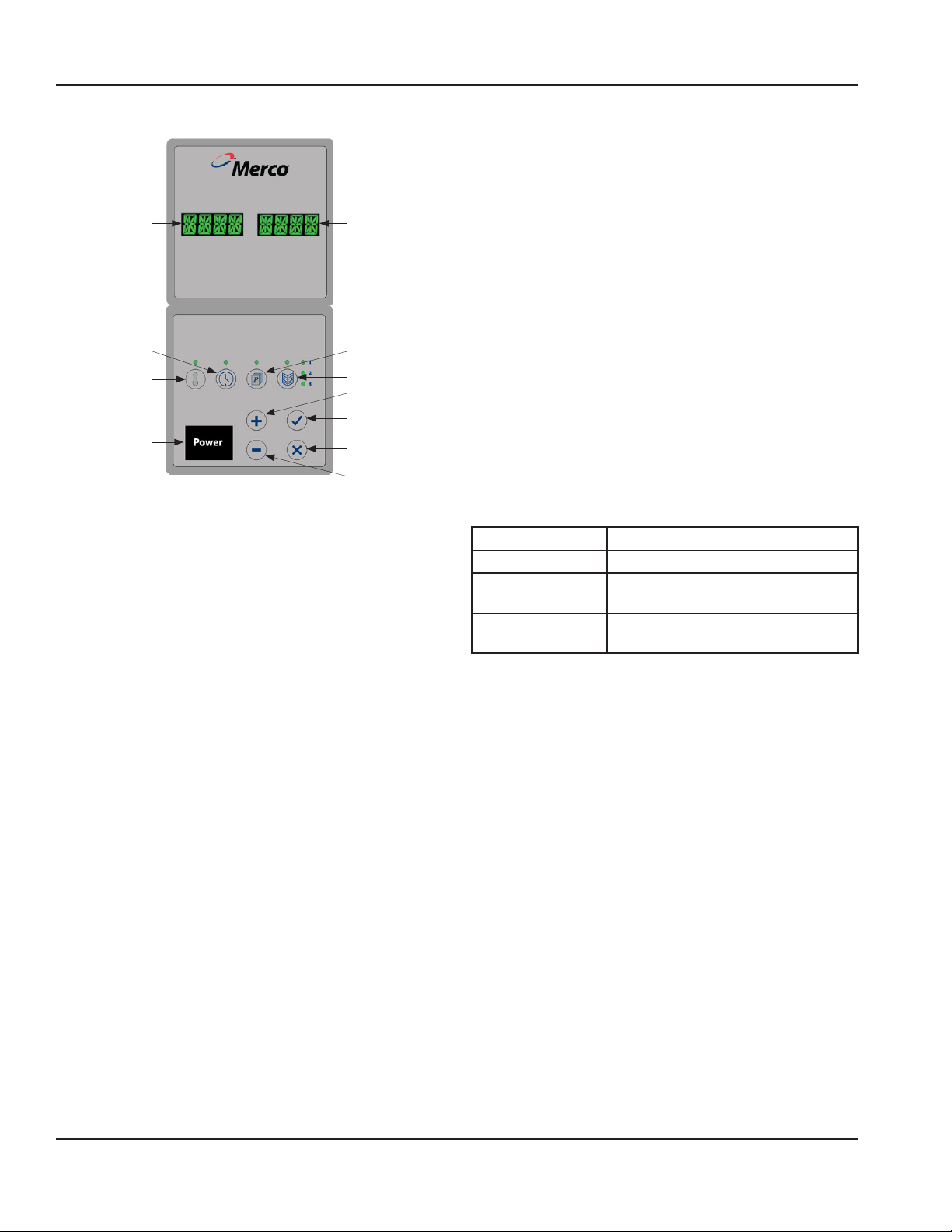
Control Panel
Left Display
Time Button
(nonfunctional)
Temperature
Button
Power Button
Right
Display
Program
Button
Day Part Button
Up Button
Enter Button
Cancel Button
Down Button
Controls/Programming/Settings
The Merco Holding Cabinet has been designed to afford
foodservice operators the ability to cook menu components
in advance and then gently store that product in the
holding bins until an order is received. Once that order has
been placed, the crew can assemble the order using hot
and fresh menu components from the holding bins. This
allows for operators to serve to order, helping increase
speed of service while maintaining high product quality
standards.
The holding bin controller is, at all times, operating in one
of the following modes. The indents indicate the submodes. Sub-modes are defined based on the navigation
to the mode. I.e., to get to diagnostic mode you must be in
active heating mode then enter programming mode.
• Pre-Heat Mode
• Active Heating Mode
- Programming Mode
» Diagnostic Mode
- Temperature View Mode
» Service Temperature Mode
PREHEAT MODE
The displays shall scroll the message Pre-Heating
repeatedly during pre-heat mode. The LED corresponding
to the active Day Part menu configuration will be on. Once
a heater has reached 180°F (82°C), it will be regulated to
the set point. The PRE-HEAT mode will be terminated when
all of the heaters have reached 180°F (82°C) OR 15 minutes
have passed.
During Pre-Heat mode, all button presses will be ignored
except the check mark button. If the check mark button
is pressed and held for (3) seconds, the displays will scroll
the message, Cancel Pre-Heat? If the check mark button
is pressed again, the unit will Cancel the Pre-Heat mode
and enter Active Heating Mode. If the cancel (X) button is
pressed, the unit shall return to Pre-Heat Mode.
ACTIVE HEATING MODE
This is the active heating mode of operation. In active
heating mode the displays will be blank and the day part
LED light will be ON.
Typical Operator Actions
Action Instructions
Turn Unit On Push Power button.
Load bin with
product
Empty bin Pull out tray and remove product.
Pull out tray, load product and reinsert
tray.
Reinsert tray.
When the unit is first powered ON, the software version
will scroll across the display. It will then begin to preheat.
Allow it to preheat for 15 minutes, the display will scroll
Preheating.
During active heating mode, press enter to scroll the
software version on the display.
12 Part Number MHCFA_Service Manual 03/16
Page 13
Section 3 Operation
PROGRAMMING MODE
Press the program button to enter the programming mode.
Zone and temperature will display. The zone will flash,
press the up or down button to reach the desired zone.
Press the day part button until the desired day part LED is
ON. Press the temperature button and both the zone and
temperature will flash. Press the up or down button to reach
the desired temperature. The program button LED light will
flash, indicating a program change has occurred. Press enter
or the temperature button to return to the zone selection,
the zone will flash. Press the program button to exit.
DIAGNOSTIC MODE
From Programming mode, press the program button and
hold for 3 seconds to enter Diagnostic Mode.
The software shall track the state of each thermocouple and
the state of the thermocouple reading compared to the set
point.
If the software finds an error, it will begin to time it. When
the timer reaches 15 minutes, an error code(s) will display
(flash) on the screen. This shall continue indefinitely.
Turning Off and On a unit will clear all TC State Display flags
and reset all TC temp timer’s to 0.
TC Display Codes
Left Display Right Display
ZaEr b_cd
a b c d
Zone Location
with Error
1
2
3
4
5
6
7
8
Section of
Zone with
Error
U=Upper
L=Lower
Thermocouple
State
0 = Ok
1 = Shorted
2 = Open
Thermocouple
reading compared
to Set point
0 = Within Range
1 = Below Range
2 = Above Range
TEMPERATURE VIEW MODE
Enter the temperature view mode by pressing the
temperature button. The average temperature in the first
zone will be displayed. Press the up or down button to scroll
through zones. Zones progress from left to right, top to
bottom. Press the temperature button or the cancel button
to exit.
TEMPERATURE SERVICE MODE
Press the temperature button or when already in the
temperature view mode press and the hold temperature
button to display the actual thermocouple temperature.
This is called the temperature service mode. Press the up
or down button to scroll through zones. U stands for upper,
L for lower. Press the temperature button or the cancel
button to exit.
During temperature service mode if the DOWN button
is held for 3 seconds the temperature display shall
be replaced with the word OFF, and the zone shall be
considered OFF. If a zone is considered OFF, the triac
outputs shall be set to off regardless of the thermocouple
feedback for that zone. No alarms shall be initiated for a
zone that is off.
TIME BUTTON
The time button has no function currently. Time will be
displayed on the Timer Bar.
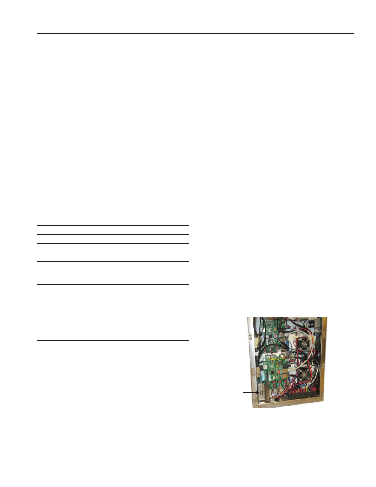
LOAD NEW SOFTWARE VIA USB
Firmware file must be loaded onto the top level of USB
instead of in a folder.
While the unit is OFF, insert the new software USB into the
port. Turn the unit ON by pushing the power button. The
unit will detect the software and begin installation. The
display will scroll Updating Firmware, then Preheating.
When Preheating is scrolling it is clear to remove the USB.
USB Port
Part Number MHCFA_Service Manual 03/16 13
Page 14

Operation Section 3
THIS PAGE INTENTIONALLY LEFT BLANK
14 Part Number MHCFA_Service Manual 03/16
Page 15
Section 4
Maintenance
DANGER
All utility connections and fixtures must be maintained
in accordance with Local and national codes.
DANGER
It is the responsibility of the equipment owner to
perform a Personal Protective Equipment Hazard
Assessment to ensure adequate protection during
maintenance procedures.
DANGER
Failure to disconnect the power at the main power
supply disconnect could result in serious injury or death.
The power switch DOES NOT disconnect all incoming
power.
DANGER
Always discharge the ht capacitors before working on
the oven using a suitably insulated 10mo resistor.
DANGER
Disconnect electric power at the main power disconnect
for all equipment being serviced. Observe correct
polarity of incoming line voltage. Incorrect polarity can
lead to erratic operation.
Cleaning and Sanitizing Procedures
GENERAL
You are responsible for maintaining the equipment
in accordance with the instructions in this manual.
Maintenance procedures are not covered by the warranty.
Maintenance Daily After Prolonged
Shutdown
Exterior X X X
Interior X X X
Holding Bin, Bin Lid
& Jet Plate
Plastic Tray X X X
EXTERIOR CLEANING
Never use a high-pressure water jet for cleaning or hose
down or flood interior or exterior of units with water. Do
not use power cleaning equipment, steel wool, scrapers
or wire brushes on stainless steel or painted surfaces.
Never use an acid based cleaning solution on exterior
panels! Many food products have an acidic content,
which can deteriorate the finish. Be sure to clean the
stainless steel surfaces of ALL food products.
X X X
Warning
n
Caution
,
At Start-Up
Warning
n
When using cleaning fluids or chemicals, rubber gloves
and eye protection (and/or face shield) must be worn.
Caution
,
Maintenance and servicing work other than cleaning as
described in this manual must be done by an authorized
service personnel.
Part Number MHCFA_Service Manual 03/16 15
The stainless steel outer case requires nothing more than
a daily wiping with a damp cloth. If, however, an excessive
amount of food particles/grease are allowed to collect, a
non-abrasive cleaner (hot sudsy water) may be used. Wipe
dry with a clean, soft cloth.
Always rub with the “grain” of the stainless steel to avoid
marring the finish. Never use steel wool or abrasive pads
for cleaning. Never use chlorinated, citrus based or abrasive
cleaners.
Stainless steel exterior panels have a clear coating that
is stain resistant and easy to clean. Products containing
abrasives will damage the coating and scratch the panels.
Daily cleaning may be followed by an application of
stainless steel cleaner which will eliminate water spotting
and fingerprints. Early signs of stainless steel breakdown
are small pits and cracks. If this has begun, clean thoroughly
and start to apply stainless steel cleaners in attempt to
restore the steel.
Page 16
Maintenance Section 4
INTERIOR CLEANING
Caution
,
Do not use caustic cleaners on any part of the oven or
oven cavity . Use mild, non abrasive soaps or detergents,
applied with a sponge or soft cloth. Never use sharp
implements or harsh abrasives on any part of the oven.
The product holding bin, bin lid and jet plate may be
cleaned via dishwasher or with warm soapy water. Care
must be taken to prevent water or cleaning compounds
from getting on internal parts, especially the switches on
the control panel.
PLASTIC TRAY CLEANING
Caution
,
Environmental stress cracking can occur, proper dilution
and rinsing per detergent manufacturers’ directions are
mandatory.
Food-approved detergents can be used if they are diluted
per manufacturers’ directions and adequately rinsed
away prior to high temp drying cycle. Basic alcohols such
as isopropyl are acceptable for hard-to-remove stains.
Otherwise, do not use organic solvents.
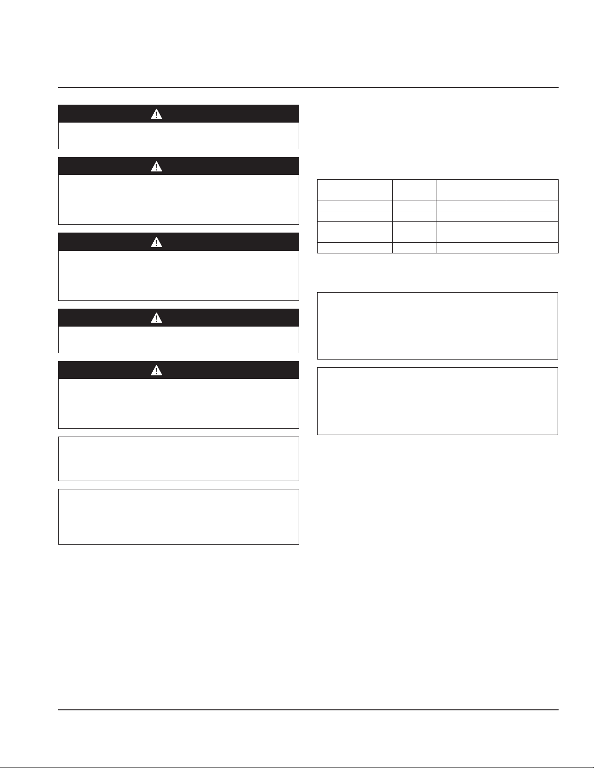
DAILY CLEANING INSTRUCTIONS
Unit must be cool to touch and disconnected from
power source.
1. Wipe the stainless steel outer case with a damp cloth,
rubbing with the grain of the steel. If an excessive
amount of food particles/grease has collected, hot
sudsy water (non-abrasive) may be used.
2. Remove bins.
16 Part Number MHCFA_Service Manual 03/16
Page 17
Section 4 Maintenance
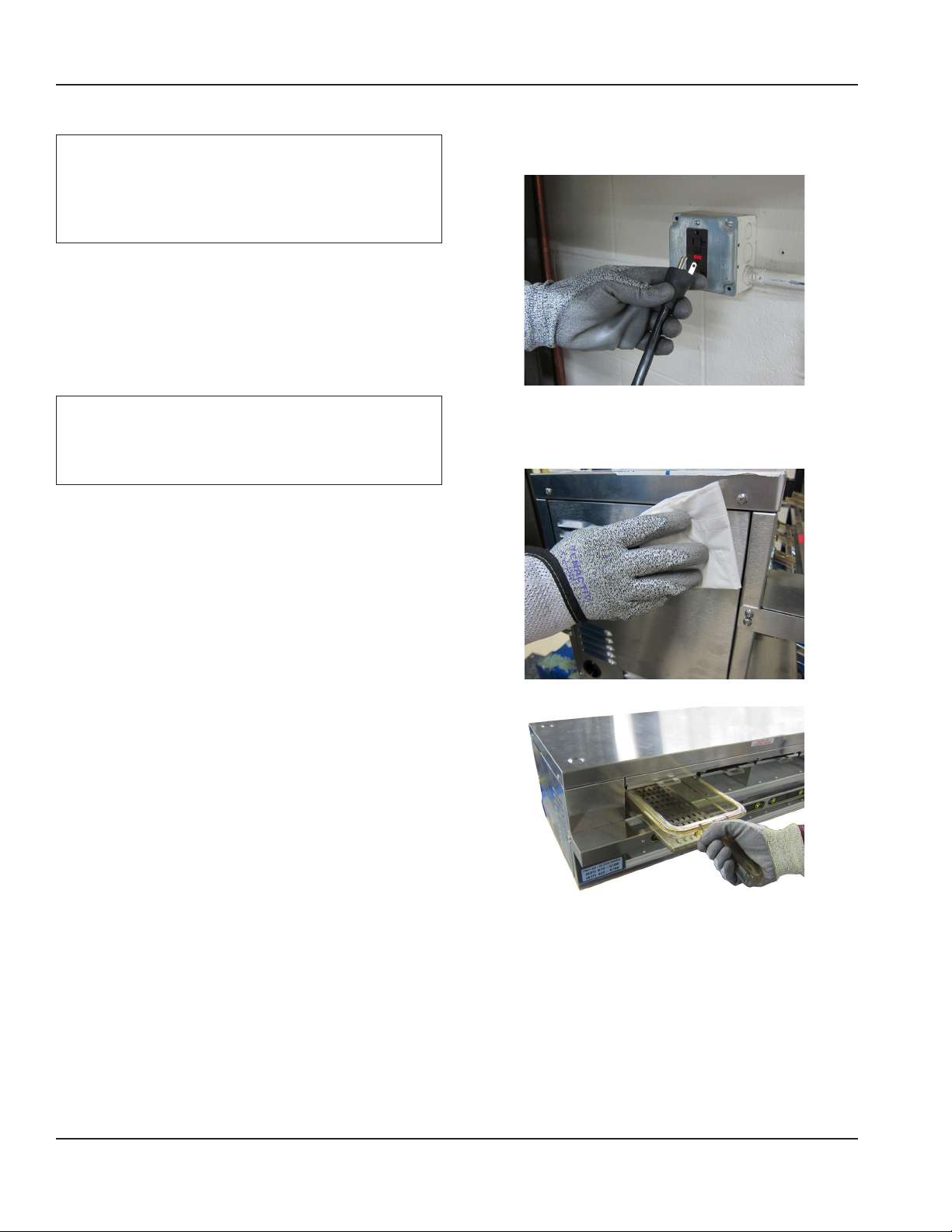
3. Twist each jet plate assembly lever counter clockwise
into the horizontal unlocked position.
4. Remove jet plate assemblies.
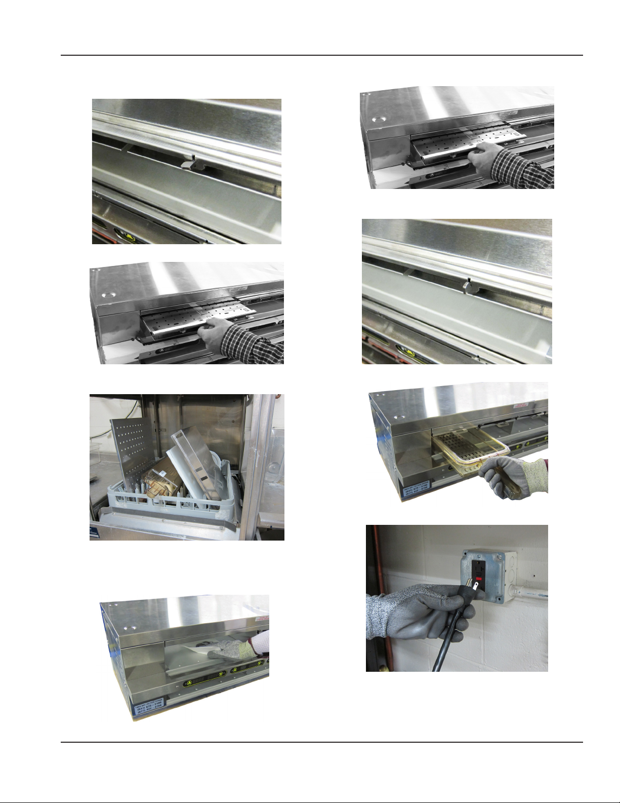
7. Reinstall the cleaned jet plate assemblies.
8. Twist each jet plate assembly lever clockwise into the
vertical locked position.
5. The product holding bins, bin lids and jet plates may be
cleaned via dishwasher or with warm soapy water.
6. Wipe the interior bottom with a damp cloth. If,
however, an excessive amount of food particles/grease
has collected, hot sudsy water (non-abrasive) may be
used.
9. Reinstall the cleaned bins.
10. Plug the unit in.
Part Number MHCFA_Service Manual 03/16 17
Page 18
Maintenance Section 4
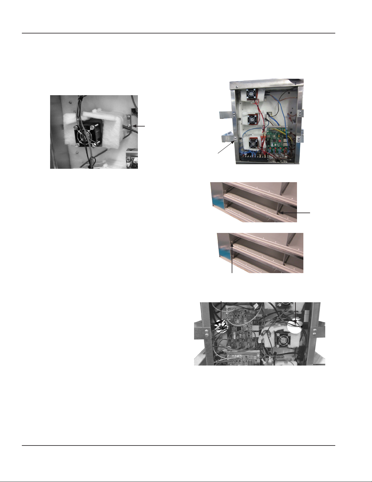
INSTRUCTIONS FOR REPLACING AN AIR HEATER
1. Remove end panel.
2. Disconnect heater hot wire from I/O board and neutral
wire from terminal block.
3. Remove the fasteners securing the air heater to the
chassis.
4. Install new air heater with fasteners.
5. Reconnect electrical and reinstall end panel.
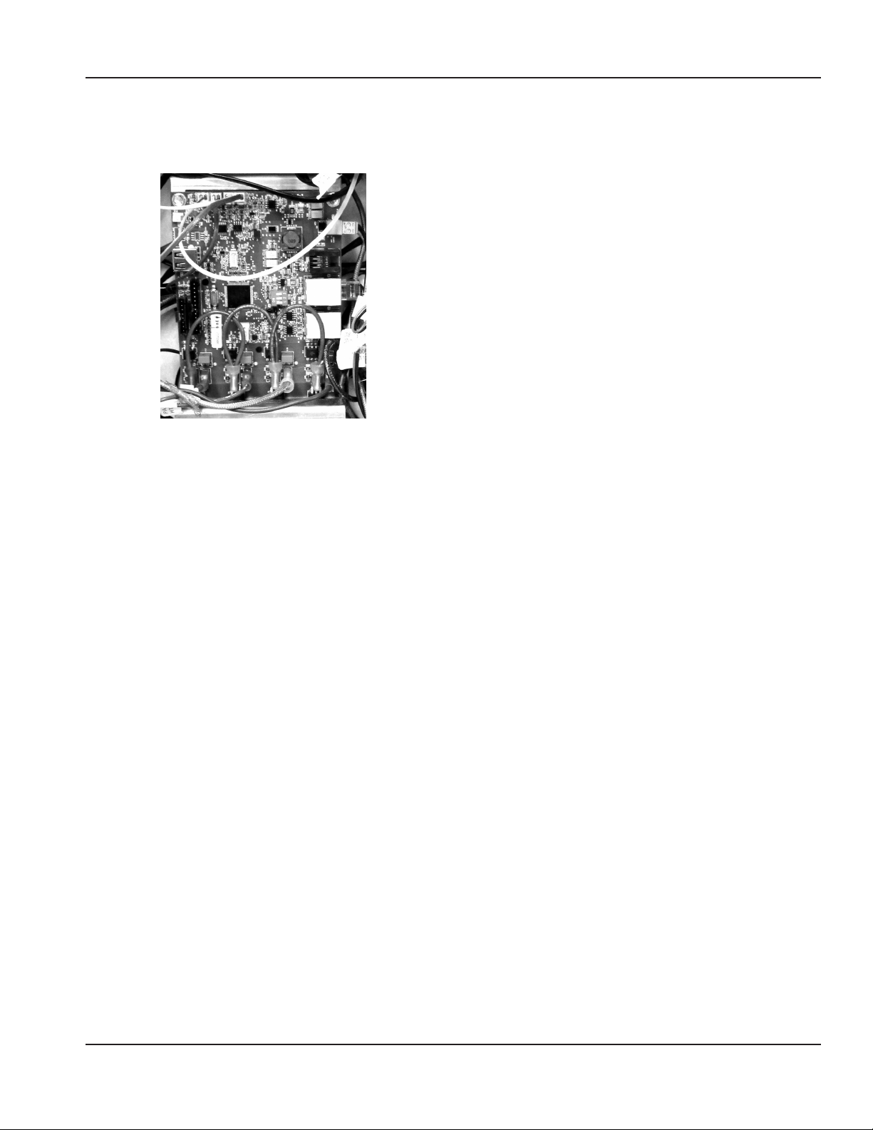
INSTRUCTIONS FOR REPLACING AN AIR HEATER
PROBE
Air heater probes are located in the panel above the zone.
Top Zone Air Heater Probe Replacement
1. Remove the unit top.
2. Remove the insulation.
3. Remove probe, it will be thoroughly taped in place.
4. Tape a new probe in it’s place and put the machine
back together.
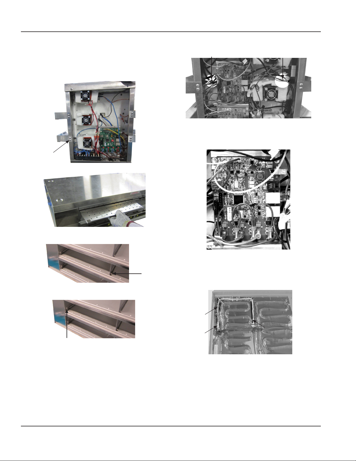
Lower Zone Air Heater Probe Replacement
These air heater probes are taped in the aluminum plate above
the zone.
1. Remove the Timer Bar above the zone.
2. Remove center divider above the zone via two screws
(US Models).
3. Remove both end clips above the zone via two screws.
4. Remove end panels.
5. From each side remove screws holding in aluminum
plate above zone.
18 Part Number MHCFA_Service Manual 03/16
Page 19
Section 4 Maintenance
6. From both sides unplug heaters and probes associated
with aluminum plate above zone. Hot wires are
plugged into the I/O board and neutral wires are
connected to the terminal block.
7. Raise aluminum plate and insulation to gain access to
air heater probe below.
8. Remove and replace air heater probe.
9. Put unit back together.
Part Number MHCFA_Service Manual 03/16 19
Page 20
Maintenance Section 4
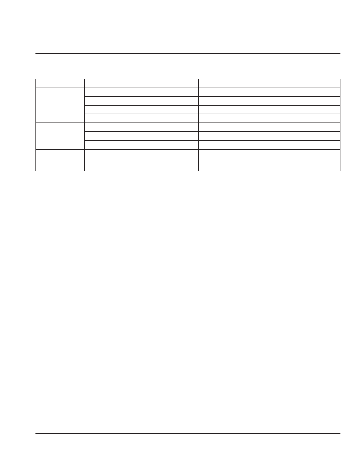
INSTRUCTIONS FOR REPLACING A HEATER PAD OR
PAD HEATER PROBE
Pad heater probes are located in the pad heater assembly.
1. Remove the Timer Bar that is in front of the pad heater.
It will be below the zone.
2. Remove jet plates above pad heater.
6. From each side remove screws holding in aluminum
plates.
7. From both sides unplug heaters and probes associated
with the heater pad. Hot wires are plugged into the I/O
board and neutral wires are connected to the terminal
block.
3. Remove center divider above heater pad via two screws
(US Models).
4. Remove both end clips above heater pad via two
screws.
5. Remove end panels.
8. Pull the aluminum plate out carefully.
9. Heater Probe Replacement
Flip the aluminum plate over. Peel the probe out of the
heater pad. The probe has brown insulation. Tape a new
probe in it’s place
10. Heater Pad Replacement
Flip the aluminum plate over. Peel the heater pad off
and stick a new one on.
11. Put the machine back together.
20 Part Number MHCFA_Service Manual 03/16
Page 21
Section 5
Troubleshooting
Troubleshooting Chart
Problem Cause Correction
Cabinet not
running
Cabinet
temperature is too
high
Cabinet
temperature is too
low
Fuse blown or circuit breaker tripped. Replace fuse or reset circuit breaker.
Power cord unplugged. Plug in power cord.
Thermostat set too high. Set thermostat to lower temperature.
Main power switch turned off. Turn main power switch on.
Thermostat set too high. Set thermostat to lower temperature.
Poor air circulation in cabinet. Re-arrange product to allow proper air circulation.
Exterior thermometer is out of calibration. Re-calibrate thermometer.
Jet plate out of unit. Reinstall jet plate.
Pans out of unit. Reinstall pans in unit.
Part Number MHCFA_Service Manual 03/16 21
Page 22

Troubleshooting Section 5
THIS PAGE INTENTIONALLY LEFT BLANK
22 Part Number MHCFA_Service Manual 03/16
Page 23

Section 6
Controls
Control Troubleshooting
TC Display Codes
Left Display Right
Display
ZaEr b_cd
a b c d
Zone Location with Error Section of Zone with Error Thermocouple State Thermocouple reading
compared to Set point
1
2
3
4
5
6
7
8
U=Upper
L=Lower
Upper Zone Thermocouple Shorted - Right Display Error
Code U_1d
1. Remove the jet plate and inspect the air heater probe
near the upper baffle.
2. If end of probe is touching metal, move it. If the error
clears, repair the end by adding high temp heat tape
rated at 392°F or silicone sleeve to the probe end.
3. If moving or taping probe end doesn’t fix error code,
short is some place else.
4. Remove side panel.
5. Inspect probe wire where it connects to I/O board.
6. Check probe continuity to chassis.
7. Check continuity through probe.
8. Swap probe with error with an error free probe.
Thermocouple state checks every 5 seconds. If error
location switches, replace probe.
Lower Zone Thermocouple Shorted - Right Display Error
Code L_1d
1. There is no physical inspection for the hot end of the
pad heater probe.
2. Inspect probe wire where it connects to I/O board.
3. Check probe continuity to chassis. If probe is grounded
to chassis replace probe.
4. Swap probe with error with an error free probe.
Thermocouple state checks every 5 seconds. If error
location switches, replace probe or pad.
Thermocouple Is Open - Right Display Error Code b_2d
1. Unplug the probe from the I/O board.
2. Check that end of probe has a ramp shape and there is
3. Plug probe back into I/O board, confirm connection
4. Check continuity through probe, if probe is open probe
5. Swap probe with error with an error free probe.
0 = Ok
1 = Shorted
2 = Open
0 = Within Range
1 = Below Range
2 = Above Range
no visible oxidation.
snaps.
must be replaced.
Thermocouple state checks every 5 seconds. If error
location switches, replace probe.
Part Number MHCFA_Service Manual 03/16 23
Page 24

Controls Section 6
Thermocouple Reading is Below or Above Set Point Right Display Error Code b_c1 or b_c2
1. Document all temperature readings for unit, each zone,
upper and lower.
2. If the zone probes are switched, there will be two
errors, one high and one low.
3. Check the I/O boards where the probes with errors plug
in. There is yellow insulation jacket on the air probes
and brown insulation jacket on the pad probes. Check
that the probes alternate (yellow brown yellow brown)
and are plugged in properly.
4. Heater outputs could be swapped, there will be two
errors. Air heaters have yellow fiberglass wire. Pad
heaters have brown silicone wire. Check that the wires
alternate (fiberglass silicone fiberglass silicone).
5. The I/O board triac could be shorted or open. An
orange LED is associated with each triac, it signals if the
triac should be on or off.
6. Isolate each triac wire and check the amperage.
• If the triac is supposed to be open and there is
no current, the problem could be a heater. Check
continuity through heating element.
• If the triac light does not match the amperage,
the triac is failing and the I/O board needs to be
replaced.
• Check input and output of triac, this could signal an
I/O board failure.
24 Part Number MHCFA_Service Manual 03/16
Page 25

Kitchen Minder
PHU 1
PHU 7
COM3 COM2 COM1
PHU 2
PHU 6
PHU 8
PHU 9
PHU 5
PHU 3
BOH
Serial Port
Programming
Power
2x4,4x2,2x3 or 2x2
2x4,4x2,2x3 or 2x2
2x4, 4x2, 2x3 & 2x2 PPHU and SPHU mix and
devices) Up to 9 PHU’s are supported
KM Power
Section 7
ICC Timer Bar and Kitchen Minder
For ICC Timer Bar and Kitchen Minder connection questions and issues call - ICC Tech Division 631-673-5100 or
877-422-8788.
Connections
Merco PHU’s with Alpha/Numeric Timer Bars to a Kitchen Minder system.
Use one of the following 3 diagrams that best fits your restaurant configuration.
It also is possible to mix and match from COM1, COM2 and COM 3 of the 3 diagrams. Any Secondary PHU may be left out
and any full COM port can be left out but must be filled COM1 first, then 2, then 3.
match connection diagram (rear perspective of
Computer
RS-232
Outlet
Supply
Primary PHU’s
(PPHU)
PHU 4
Secondary PHU’s
(SPHU)
= ICC 6 position flat cable
up to 25’
= ICC or any standard
CAT5 Cable up to 50’
Part Number MHCFA_Service Manual 03/16 25
Page 26

ICC Timer Bar and Kitchen Minder Section 7
2x4, 4x2, 2x3 or 2x2
3x4 PPHU and 2x4, 4x2, 2x3, 2x2 SPHU mix
Kitchen Minder
PHU 1 Bottom
PHU 2 Top
COM3 COM2 COM1
PHU 3
PHU 9
PHU 6
BOH
Serial Port
Programming
Power
3x4 Primary PHU’s
KM Power
PHU 4 Bottom
PHU 5 Top
PHU 7 Bottom
PHU 8 Top
and match connection diagram (rear
perspective of devices) Up to 6 physical PHU’s
are supported
Computer
RS-232
Outlet
Supply
(PPHU)
Secondary PHU’s
(SPHU)
= ICC 6 position flat cable
up to 25’
= ICC or any standard
CAT5 Cable up to 50’
26 Part Number MHCFA_Service Manual 03/16
Page 27

Section 7 ICC Timer Bar and Kitchen Minder
3x4 Secondary PHU’s
3x4 PPHU and 3x4 SPHU connection diagram
Kitchen Minder
PHU 1 Bottom
PHU 2 Top
COM3 COM2 COM1
PHU 2 Top
PHU 3 Bottom
BOH
Serial Port
Programming
Power
3x4 Primary PHU’s
KM Power
PHU 4 Bottom
PHU 5 Top
PHU 7 Bottom
PHU 8 Top
PHU 5 Top
PHU 6 Bottom
PHU 8 Top
PHU 9 Bottom
(rear perspective of devices) Up to 6 physical
PHU’s are supported
Computer
RS-232
Outlet
Supply
(PPHU)
(SPHU)
= ICC 6 position flat cable
up to 25’
= ICC or any standard
CAT5 Cable up to 50’
Part Number MHCFA_Service Manual 03/16 27
Page 28

ICC Timer Bar and Kitchen Minder Section 7
KM1 Monochrome Unit Testing & Troubleshooting
1.1 - Testing connections
1.1.1 - Product Location Test
1.1.2 - On the KM, press the Menu key
1.1.3 - Use the down arrow to highlight Product Location and press Select key
1.1.4 - The following screen will appear:
1.1.5 - Press the Continue soft key
1.1.6 - On the KM PHU1 will display 8 pans referenced from the front of the PPHU connected to COM1 of the KM
1.1.6.1 - The upper left corner on the KM screen will be highlighted
1.1.6.1.1 - All Timer Bar LED’s will be unlit except:
1.1.6.1.2 - On a 2x4 or 4x2 PPHU, the top left pan will illuminate solid red
1.1.6.1.3 - On a 2x3 PPHU press the Select key once
1.1.6.1.3.1 - The pan on the KM will move one pan to the right
1.1.6.1.3.2 - The TB LED on the 2x3 PPHU top left pan will illuminate solid red
1.1.6.1.4 - On a 2x2 PPHU press the Select key twice
1.1.6.1.4.1 - The pan on the KM will move two pans to the right
1.1.6.1.4.2 - The Timer Bar LED on the 2x2 PPHU top left pan will illuminate solid red
1.1.6.1.5 - On a 3x4 PPHU, the middle left pan will illuminate solid red
1.1.6.1.5.1 - Press the Next soft key to advance to PHU2
1.1.6.1.5.2 - The top left pan of the 3x4 will illuminate solid red
1.1.7 - Continue in the same manner for all PHU’s connected to the KM based on the diagrams above
1.1.8 - Press the Product Status key
1.1.9 - The KM will go to Product Status screen
1.1.10 - The restaurant manager should program PC Minder with the correct products for each PHU and transfer the
data to the Kitchen Minder
28 Part Number MHCFA_Service Manual 03/16
Page 29

Section 7 ICC Timer Bar and Kitchen Minder
1.2 - Troubleshooting
1.2.1 - If a PPHU Timer Bar displays NOKM
1.2.1.1 - Check the CAT5 connection from the KM to the PPHU
1.2.1.2 - Test the CAT5 cable with a cable tester or use a known good cable
1.2.1.3 - If the connection and cable are OK, call Merco or ICC for support
1.2.2 - If a SPHU displays NOBB
1.2.2.1 - Check that the PPHU is powered on
1.2.2.2 - Check the 6 position data connection from the PPHU to the SPHU
1.2.2.3 - Check the 6 position cable with a cable tester or use a known good cable
1.2.2.4 - If the PPHU is powered on, the connection and cable are OK, call Merco or ICC for support
1.3 - End of document
Part Number MHCFA_Service Manual 03/16 29
Page 30

ICC Timer Bar and Kitchen Minder Section 7
1:1 CONNECTOR
CABLE
12.00"
BLACK
WARMER
CONTROL
ICC# 681-6X6-12
MHCFA22 Timer Bar Diagram
NOTE: “Warmer Control” on diagram is the I/O board.
BACK ICC P/N980105-2X2#
FRONT ICC P/N980105-2X2#
CABLE ASS'Y
ICC# 801195
BLACK
BLACK
12VAC
XFMR IN PHU
PRODUCT HOLDING UNIT 1
J5
J1
WMR 2
J2
J3
PHU II HUB CONTROL BOARD
A/N WITH TEMP, 2H
ICC # 810195-80#
J4
WMR 1
WMR 3
WARMER
CONTROL
CABLE CAT 5
ICC# 681-8X8-12
12.00"
877-ICC-8788
877-ICC-8788
6.00" +/- 1.00"
ICC# 681-6X6-12
CABLE
ICC# 681-6X6-12
12.00"
ICC# 681-6X6-12
6.00" +/- 1.00"
WARMER
ADAPTER
ICC# 810004
CABLE
12.00"
CABLE
12.00"
1:1 CONNECTOR
BACK ICC P/N980105-2X2#
FRONT ICC P/N980105-2X2#
F
B
CABLE ASS'Y
ICC# 801195
BLACK
BLACK
J1
J2
TO STATION
INTERFACE BOX
CABLE
12.00"
VCC
SECONDARY PHU POWER
SUPPLY BOARD
ICC 810680#-1
1:1 CONNECTOR
CABLE
ICC# 681-6X6-96
96.00"
1:1 CONNECTOR
CABLE
ICC# 681-6X6-12
12.00"
WARMER
CONTROL
WARMER
ADAPTER
ICC# 810004
12VAC
XFMR IN PHU
ICC# 681-6X6-12
F
B
J4
KEYBD
FRONT
J3
KEYBD
BACK
877-ICC-8788
6.00" +/- 1.00"
877-ICC-8788
6.00" +/- 1.00"
PRODUCT HOLDING UNIT 2
1:1 CONNECTOR
CABLE
ICC# 681-6X6-96
96.00"
CAT 5
CABLE TO KITCHEN MINDER
ICC# 681-6X6-12
1:1 CONNECTOR
BACK ICC P/N980105-2X2#
FRONT ICC P/N980105-2X2#
CABLE ASS'Y
ICC# 801195
BLACK
BLACK
XFMR IN PHU
WARMER
CONTROL
CABLE
12.00"
WARMER
ADAPTER
ICC# 810004
12VAC
CABLE
ICC# 681-6X6-12
12.00"
F
B
J1
J2
TO STATION
INTERFACE BOX
VCC
SECONDARY PHU POWER SUPPLY BOARD
ICC 810680#-1
KEYBD
FRONT
KEYBD
BACK
J4
J3
877-ICC-8788
877-ICC-8788
6.00" +/- 1.00"
6.00" +/- 1.00"
PRODUCT HOLDING UNIT 3
30 Part Number MHCFA_Service Manual 03/16
Page 31

Section 7 ICC Timer Bar and Kitchen Minder
1:1 CONNECTOR
CABLE
12.00"
ICC# 681-6X6-12
WARMER
CONTROL
MHCFA23 Timer Bar Diagram
NOTE: “Warmer Control” on diagram is the I/O board.
BACK ICC P/N 980105-2X3#
FRONT ICC P/N 980105-2X3#
CABLE ASS'Y
ICC# 801195
BLACK
BLACK
12VAC
XFMR IN PHU
PRODUCT HOLDING UNIT 1
WARMER
CONTROL
J2
J1
PHU II HUB CONTROL BOARD
A/N WITH TEMP, 2H
ICC # 810195-80#
J5
WMR 1
J4
WMR 2
J3
WMR 3
ICC# 681-8X8-12
CABLE CAT 5
12.00"
877-ICC-8788
8
7
7
-
I
C
C
-
8
7
8
8
877-ICC-8788
877-ICC-8788
6.00" +/- 1.00"
ICC# 681-6X6-12
CABLE
ICC# 681-6X6-12
12.00"
ICC# 681-6X6-12
6.00" +/- 1.00"
F
B
WARMER
ADAPTER
ICC# 810004
CABLE
12.00"
1:1 CONNECTOR
CABLE
ICC# 681-6X6-96
96.00"
CABLE
12.00"
1:1 CONNECTOR
1:1 CONNECTOR
CAT 5
BACK ICC P/N 980105-2X3#
FRONT ICC P/N 980105-2X3#
1:1 CONNECTOR
CABLE
ICC# 681-6X6-12
12.00"
CABLE TO KITCHEN MINDER
BACK ICC P/N 980105-2X3#
FRONT ICC P/N 980105-2X3#
BLACK
BLACK
WARMER
CONTROL
WARMER
ADAPTER
ICC# 810004
PRODUCT HOLDING UNIT 2
ICC# 681-6X6-96
877-ICC-8788
8
7
6.00" +/- 1.00"
7-
I
C
C
-8
78
8
877-ICC-8788
8
7
7
-I
C
C
-8
7
88
6.00" +/- 1.00"
CABLE ASS'Y
ICC# 801195
12VAC
XFMR IN PHU
F
B
CABLE
96.00"
CABLE
ICC# 681-6X6-12
12.00"
J2
J1
TO STATION
INTERFACE BOX
VCC
SECONDARY PHU POWER
SUPPLY BOARD
ICC 810680#-1
877-ICC-8788
8
7
7
-IC
C
-
8
7
8
8
877-ICC-8788
87
7
-
IC
C
-
8
7
8
8
6.00" +/- 1.00"
J4
KEYBD
FRONT
J3
KEYBD
BACK
6.00" +/- 1.00"
CABLE ASS'Y
ICC# 801195
BLACK
CABLE
ICC# 681-6X6-12
12.00"
1:1 CONNECTOR
WARMER
CONTROL
WARMER
ADAPTER
ICC# 810004
BLACK
12VAC
XFMR IN PHU
B
J2
J1
CABLE
F
ICC# 681-6X6-12
12.00"
J4
KEYBD
FRONT
J3
TO STATION
KEYBD
INTERFACE BOX
BACK
VCC
SECONDARY PHU POWER
SUPPLY BOARD
ICC 810680#-1
PRODUCT HOLDING UNIT 3
Part Number MHCFA_Service Manual 03/16 31
Page 32

ICC Timer Bar and Kitchen Minder Section 7
CABLE TO KITCHEN MINDER
PRODUCT HOLDING UNIT 2
BACK ICC P/N 980240#
FRONT ICC P/N 980240# FRONT ICC P/N 980240#
1:1 CONNECTOR
ICC# 681-6X6-12
CABLE
12.00"
CABLE
96.00"
ICC# 681-6X6-96
CABLE
12.00"
ICC# 681-6X6-12
WARMER
ADAPTER
ICC# 810004
F
B
WARMER
CONTROL
PRODUCT HOLDING UNIT 3
BACK ICC P/N 980240#
FRONT ICC P/N 980240#
1:1 CONNECTOR
CABLE
12.00"
ICC# 681-6X6-12
WARMER
ADAPTER
ICC# 810004
F
B
WARMER
CONTROL
MHCFA24 Timer Bar Diagram
NOTE: “Warmer Control” on diagram is the I/O board.
BACK ICC P/N 980240#
FRONT ICC P/N 980240#
CABLE ASS'Y
BLACK
BLACK
ICC# 801195
12VAC
XFMR IN PHU
PRODUCT HOLDING UNIT 1
6.00" +/- 1.00"
8
7
7
IC
C
-8
78
8
8
7
7
-I
C
C
8
7
8
8
6.00" +/- 1.00"
WARMER
CONTROL
CABLE
ICC# 681-6X6-12
12.00"
J5
WMR 1
WMR 2
J4
J2
J1
STATION INTERFACE CON TROL BOARD
ICC # 810195-80#
WMR 3
J3
CABLE
ICC# 681-8X8-12
12.00"
F
B
WARMER
ADAPTER
ICC# 810004
CAT 5
1:1 CONNECTOR
CABLE
ICC# 681-6X6-96
96.00"
1:1 CONNECTOR
1:1 CONNECTOR
BACK ICC P/N 980240#
FRONT ICC P/N 980240#
8
7
7
I
C
C
8
7
8
8
8
7
7
-I
C
C
8
7
8
8
6.00" +/- 1.00"
6.00" +/- 1.00"
1:1 CONNECTOR
1:1 CONNECTOR
WARMER
CABLE
ICC# 681-6X6-12
12.00"
CABLE TO KITCHEN MINDER
CONTROL
WARMER
ADAPTER
ICC# 810004
B
F
PRODUCT HOLDING UNIT 2
CABLE
ICC# 681-6X6-96
96.00"
CABLE
ICC# 681-6X6-12
12.00"
32 Part Number MHCFA_Service Manual 03/16
Page 33

Section 7 ICC Timer Bar and Kitchen Minder
Continued MHCFA24 Timer Bar Diagram
NOTE: “Warmer Control” on diagram is the I/O board.
1:1 CONNECTOR
WARMER
CONTROL
CABLE
ICC# 681-6X6-12
12.00"
BACK ICC P/N 980240#
FRONT ICC P/N 980240#
B
WARMER
ADAPTER
ICC# 810004
F
1:1 CONNECTOR
CABLE
ICC# 681-6X6-12
12.00"
PRODUCT HOLDING UNIT 3
8
6.00" +/- 1.00"
77
I
C
C
8
7
8
8
8
7
7
IC
C
87
8
8
Part Number MHCFA_Service Manual 03/16 33
Page 34

ICC Timer Bar and Kitchen Minder Section 7
MHCFA34 Timer Bar Diagram
NOTE: “Warmer Control” on diagram is the I/O board.
FRONT ICC P/N 980105-1X4#
FRONT ICC P/N 980105-2X4#
CABLE ASS'Y
12VAC
XFMR IN PHU
ICC# 801195
BLACK
BLACK
PRODUCT HOLDING UNIT 1
FRONT ICC P/N 980105-1X4#
FRONT ICC P/N 980105-2X4#
WARMER
CONTROL
J2
J1
PHU II HUB CONTROL BOARD
A/N WITH TEMP, 3H
ICC # 810195-83#
WMR 1
J5
J4
WMR 2
J3
CABLE NOT TO EXCEED
60.00" IN LENGTH
WMR 3
6.00" +/- 1.00"
8
77
I
CC
-8
7
8
8
87
6.00" +/- 1.00"
7I
C
C
-8
78
8
CABLE
ICC# 681-6X6-12
12.00"
CABLE
ICC# 681-8X8-12
12.00"
8
77
I
CC
-8
7
8
8
87
7I
C
C
-8
78
8
F
6.00" +/- 1.00"
6.00" +/- 1.00"
B
WARMER
ADAPTER
ICC# 810004
6.00" +/- 1.00"
6.00" +/- 1.00"
MODIFIED TEE
B
F
PIN 1 TO PIN 1
ICC# 802008
ICC# 681-6X6-12
CABLE NOT TO EXCEED
60.00" IN LENGTH
CABLE
ICC# 681-6X6-12
12.00"
CABLE
12.00"
6.00" +/- 1.00"
6.00" +/- 1.00"
877-ICC-8788
877-ICC-8788
BACK ICC P/N 980105-2X4#
1:1 CONNECTOR
CABLE
ICC# 681-6X6-96
96.00"
CAT 5
1:1 CONNECTOR
CABLE TO KITCHEN MINDER
BACK ICC P/N 980105-1X4#
877-ICC-8788
BACK ICC P/N 980105-1X4#
877-ICC-8788
BACK ICC P/N 980105-2X4#
TEE CONNECTOR
PIN 1 TO PIN 1
ICC# 633101
CABLE
ICC# 681-6X6-12
12.00"
CABLE NOT TO EXCEED
60.00" IN LENGTH
WARMER
CONTROL
1:1 CONNECTOR
CABLE
ICC# 681-6X6-12
12.00"
BLACK
WARMER
ADAPTER
ICC# 810004
TEE CONNECTOR
PIN 1 TO PIN 1
ICC# 633101
CABLE
ICC# 681-6X6-12
12.00"
CABLE ASS'Y
12VAC
XFMR IN PHU
ICC# 801195
CABLE
ICC# 681-6X6-12
12.00"
J1
J2
TO STATION
INTERFACE BOX
VCC
SECONDARY PHU POWER SUPPLY BOARD
ICC 810680#-1
BLACK
F
B
CABLE NOT TO EXCEED
60.00" IN LENGTH
J4
KEYBD
FRONT
J3
KEYBD
BACK
PRODUCT HOLDING UNIT 2
34 Part Number MHCFA_Service Manual 03/16
Page 35

Section 7 ICC Timer Bar and Kitchen Minder
BLACK
BLACK
BACK
FRONT
BACK
1:1 CONNECTOR
ICC# 681-6X6-12
CABLE
12.00"
WARMER
CONTROL
F
B
WARMER
ADAPTER
ICC# 810004
ALPHA/NUMERIC 2 WIDE KEYBOARD ICC P/N 980105-2X2#-T
ALPHA/NUMERIC 2 WIDE KEYBOARD ICC P/N 980105-2X2#
ALPHA/NUMERIC 2 WIDE KEYBOARD ICC P/N 980105-2X2#-T
ALPHA/NUMERIC 2 WIDE KEYBOARD ICC P/N 980105-2X2#
MHCFA42 Timer Bar Diagram
NOTE: “Warmer Control” on diagram is the I/O board.
BACK
ALPHA/NUMERIC 2 WIDE KEYBOARD ICC P/N 980105-2X2#-T
ALPHA/NUMERIC 2 WIDE KEYBOARD ICC P/N 980105-2X2#
6.00" +/- 1.00"
8
7
7
6.00" +/- 1.00"
I
C
C
-8
7
8
8
UNMODIFIED TEE
PIN 1 TO PIN 1
ICC# 633101
CABLE
ICC# 681-6X6-12
12.00"
ALPHA/NUMERIC 2 WIDE KEYBOARD ICC P/N 980105-2X2#-T
ALPHA/NUMERIC 2 WIDE KEYBOARD ICC P/N 980105-2X2#
6.00" +/- 1.00"
877-ICC-8788 877-ICC-8788
6.00" +/- 1.00"
UNMODIFIED TEE
PIN 1 TO PIN 1
ICC# 633101
CABLE
ICC# 681-6X6-12
12.00"
FRONT
ALPHA/NUMERIC 2 WIDE KEYBOARD ICC P/N 980105-2X2#-T
ALPHA/NUMERIC 2 WIDE KEYBOARD ICC P/N 980105-2X2#
CABLE ASS'Y
BLACK
ICC# 801195
BLACK
12VAC
XFMR IN PHU
PRODUCT HOLDING UNIT 1
8
7
7
I
C
C
8
7
8
8
6.00" +/- 1.00"
6.00" +/- 1.00"
J1
J2
PHU II HUB CONTROL BOARD
A/N WITH TEMP, 2H
ICC # 810195-80#
UNMODIFIED TEE
WARMER
CONTROL
WMR 2
PIN 1 TO PIN 1
ICC# 633101
WMR 1
J5
J4
WMR 3
J3
CABLE CAT 5
ICC# 681-8X8-12
12.00"
CABLE
ICC# 681-6X6-12
12.00"
ICC# 681-6X6-12
CABLE NOT TO EXCEED
60.00" IN LENGTH
ALPHA/NUMERIC 2 WIDE KEYBOARD ICC P/N 980105-2X2#-T
ALPHA/NUMERIC 2 WIDE KEYBOARD ICC P/N 980105-2X2#
CABLE
12.00"
CABLE
ICC# 681-6X6-12
12.00"
ICC# 681-6X6-12
BACK
B
F
WARMER
ADAPTER
ICC# 810004
1:1 CONNECTOR
CABLE
12.00"
1:1 CONNECTOR
1:1 CONNECTOR
CAT 5
CABLE
ICC# 681-6X6-96
96.00"
ALPHA/NUMERIC 2 WIDE KEYBOARD ICC P/N 980105-2X2#-T
ALPHA/NUMERIC 2 WIDE KEYBOARD ICC P/N 980105-2X2#
WARMER
CONTROL
1:1 CONNECTOR
CABLE
ICC# 681-6X6-12
12.00"
ICC# 810004
CABLE TO KITCHEN MINDER
6.00" +/- 1.00"
UNMODIFIED TEE
8
7
6.00" +/- 1.00"
7
IC
C
8
7
8
8
PIN 1 TO PIN 1
ICC# 633101
FRONT
CABLE ASS'Y
ICC# 801195
BLACK
BLACK
12VAC
XFMR IN PHU
CABLE
ICC# 681-6X6-12
12.00"
WARMER
ADAPTER
B
F
PRODUCT HOLDING UNIT 2
CABLE
ICC# 681-6X6-96
96.00"
CABLE
ICC# 681-6X6-12
12.00"
6.00" +/- 1.00"
6.00" +/- 1.00"
J1
J2
TO STATION
INTERFACE BOX
VCC
SECONDARY PHU POWER SUPPLY BOARD
ICC 810680#-1
UNMODIFIED TEE
PIN 1 TO PIN 1
ICC# 633101
J4
KEYBD
FRONT
J3
KEYBD
BACK
CABLE
ICC# 681-6X6-12
12.00"
FRONT
ALPHA/NUMERIC 2 WIDE KEYBOARD ICC P/N 980105-2X2#-T
6.00" +/- 1.00"
8
7
6.00" +/- 1.00"
7
IC
C
-8
7
8
8
UNMODIFIED TEE
PIN 1 TO PIN 1
ICC# 633101
CABLE
ICC# 681-6X6-12
12.00"
ALPHA/NUMERIC 2 WIDE KEYBOARD ICC P/N 980105-2X2#
1:1 CONNECTOR
WARMER
CONTROL
CABLE
ICC# 681-6X6-12
12.00"
WARMER
ADAPTER
ICC# 810004
CABLE ASS'Y
ICC# 801195
BLACK
BLACK
12VAC
XFMR IN PHU
B
F
CABLE
ICC# 681-6X6-12
12.00"
J1
PRODUCT HOLDING UNIT 3
J4
KEYBD
FRONT
J3
J2
TO STATION
KEYBD
INTERFACE BOX
BACK
VCC
SECONDARY PHU POWER SUPPLY BOARD
ICC 810680#-1
Part Number MHCFA_Service Manual 03/16 35
Page 36

ICC Timer Bar and Kitchen Minder Section 7
THIS PAGE INTENTIONALLY LEFT BLANK
36 Part Number MHCFA_Service Manual 03/16
Page 37

Section 8
Charts
Zone Diagrams & Heating Element Specifications
Key Air Heater Pad Heater
MHCFA22 & MHCFA22EX
Location Heater Model Description Resistance Part Number
MHCFA22 700W, 120V 18.9Ω +/- 5% 2195351
All Zones Air Heater
All Zones Pad Heater
There are two bins per zone.
MHCFA23 & MHCFA23EX
Location Part Description Resistance Part Number
Zones 2 & 4 Air Heater, 350W, 230V 143Ω +/- 5% 2195350
Zones 2 & 4 Pad Heater, 100W, 230V 529Ω +/- 10% 2198599
MHCFA22EX 700W, 230V 18.9Ω +/- 5% 2195352
MHCFA22 330W, 120V 43.33Ω +/- 10% 2198616
MHCFA22EX 330W, 230V 43.33Ω +/- 10% 2198629
MHCFA24, MHCFA24EX & MHCFA42EX
MHCFA34 & MHCFA34EX
Location Heater Model Description Resistance Part Number
All Zones Air Heater
Zones 1 & 3 Air Heater, 700W, 230V 71.8Ω +/- 5% 2195352
Zones 1 & 3 Pad Heater, 200W, 230V 265.5Ω +/- 10% 2198598
In zones 1 & 3 there are two bins per zone.
In zones 2 & 4 there is one bin per zone.
Location Heater Model Description Resistance
MHCFA24 700W, 230V 71.8Ω +/- 5% 2195352
All Zones
All Zones Pad
Air
Heater
Heater
MHCFA24EX,
MHCFA42EX
All Models 200W, 230V 265.5Ω +/- 10% 2198598
450W, 230V 111.6Ω +/- 5% 2195358
There are two bins per zone.
MHCFA34 450W, 230V 111.6Ω +/- 5% 2195358
MHCFA34EX 350W, 230V 143.6Ω +/- 5% 2195350
Part
Number
MHCFA34 200W, 230V 265.5Ω +/- 10% 2198598
All Zones Pad Heater
MHCFA34EX 100W, 230V 529Ω +/- 10% 2198628
There are two bins per zone.
Part Number MHCFA_Service Manual 03/16 37
Page 38

Charts Section 8
System Layout
System Layout
Only 2 Secondary I/O Boards Shown
BD Board
RJ12 Cable
I/O Board (Secondary 1)
I/O Board (Secondary 2)
RJ45 Cable
RJ45 Cable
I/O Board (Primary)
SW1 and J5 settings together define the system address.
Note how small J5 Jumper is compared to a dime.
Caution
,
Ensure SW1 dip switches and J5 jumper match the old
I/O Board upon replacement.
When the jumper is in the wrong position, zones will not
display when checking temperature.
12 Pin LED Connector
8 Pin Keypad Connector
J5 Setting SW1 Setting
CI Membrane Switch
SW1
Setting
ON
ON
ON
+
1 2 3
1 2 3
1 2 3
0B
0A
J5
Setting
=
System Address
0A [PRIMARY]0A
0B [SECONDARY]
SECONDARY]
1A [
38 Part Number MHCFA_Service Manual 03/16
Page 39

Section 8 Charts
I/O Board
Caution
,
I/O Board must be loaded with software. Starting March 2016, factory will mark the backside with an orange
sticker when software is loaded.
Part Number MHCFA_Service Manual 03/16 39
Page 40

Charts Section 8
I/O Board Connections
MHCFA22 & MHCFA22EX
Primary 0A I/O Board
Zone
2 Air J22 J3
1 Air J18 J1
Heater
Type
Pad J24 J4
Pad J20 J2
MCFA23, MHCFA23EX, MHCFA24 & MHCFA24EX
Heater
Connect to:
Probe
Connect to:
Primary 0A I/O Board
Zone
4 Air J22 J3
2 Air J18 J1
Heater
Type
Pad J24 J4
Pad J20 J2
Heater
Connect to:
Connect to:
Probe
Secondary 0B I/O Board
Zone
3 Air J22 J3
1 Air J18 J1
Heater
Type
Pad J24 J4
Pad J20 J2
Heater
Connect to:
MHCFA34 & MHCFA34EX
Secondary 0B I/O Board
Zone
3 Air J22 J3
1 Air J18 J1
Heater
Type
Pad J24 J4
Pad J20 J2
Heater
Connect to:
Probe
Connect to:
Probe
Connect to:
Secondary 1A I/O Board
Zone
6 Air J22 J3
5 Air J18 J1
4 Air J22 J3
2 Air J18 J1
Heater
Type
Pad J24 J4
Pad J20 J2
Primary 0A I/O Board
Pad J24 J4
Pad J20 J2
Heater
Connect to:
Connect to:
Probe
40 Part Number MHCFA_Service Manual 03/16
Page 41

Section 8 Charts
MHCFA42EX
Secondary 0B I/O Board
Zone
3 Air J22 J3
1 Air J18 J1
Zone
4 Air J22 J3
2 Air J18 J1
Heater
Type
Pad J24 J4
Pad J20 J2
Primary 0A I/O Board
Heater
Type
Pad J24 J4
Pad J20 J2
Heater
Connect to:
Heater
Connect to:
Probe
Connect to:
Probe
Connect to:
Part Number MHCFA_Service Manual 03/16 41
Page 42

Charts Section 8
THIS PAGE INTENTIONALLY LEFT BLANK
42 Part Number MHCFA_Service Manual 03/16
Page 43

MHCFA22 - Domestic 2x2
DISPLAY B0ARD
Section 9
Wiring Diagrams
J3
J1
SW1
J6
J5
J4
I/O 0A B0ARD - ZONES 1 AND 2
USB ADAPTER CABLE TO PANEL
MEMBRANE SWITCH,12 PIN RIBBON
MEMBRANE SWITCH,8 PIN RIBBON
PN: 2195357
J2
PN:2187007
I/O 0A,J10,6PIN
J15
J14
J8
J7
J18
J17
J2 J3 J4
J1
J19
J6
J20
SW1
J5
J14
J21
YL,TC,AIR,ZONE 1
BR,TC,PAD,ZONE 1
YL,TC,AIR,ZONE 2
BR,TC,PAD,ZONE 2
J16
J11
J12
J22
J23
J10
J24
PN: 2187010
RD (+) 12VDC, TERM BLOCK
BL (-) 12VDC, TERM BLOCK
DISP BRD, J6, 6PIN
PN:2186998
SW1
TO ICC WARMER ADAPTER
PN: 2187057
J5
J17 J18
J19
J20
J21
J22
J23
J24
BR,AC L,RH TERM BLOCK
PN: 2187009
BR,PAD,ZONE 2,RH SIDE,TOP
BR,AIR, ZONE 2,RH SIDE,TOP
BR,PAD,ZONE 1,RH SIDE,BOT
BR,AIR,ZONE 1,RH SIDE,BOT
Part Number MHCFA_Service Manual 03/16 43
Page 44

Wiring Diagrams Section 9
12VDC POWER SUPPLY
MHCFA22 - Domestic 2x2
GN, TO #10 GROUND STUD
BU,AC N,RH TERM BLOCK
BR,AC L,RH TERM BLOCK
PN: 2187013
POWER SWITCH
PN:2187019
RH - TOP ZONE - ZONE 2
RD(+)12VDC,RH TERM BLOCK
BL(-)12VDC,RH TERM BLOCK
YL,I/O 0A,J3(TC,AIR,TOP)
BR,I/O 0A,J22(AIR,TOP)
BU,AC N,LH TERM BLOCK
BR,I/O 0A,J4(TC,PAD,TOP)
BR,I/O 0A,J24(PAD,TOP)
BU,AC N,LH TERM BLOCK
CN2 - 12VDC OUTPUT
CN1 - 100 TO 277VAC INPUT
BL,AC L,INCOMING POWER
WH,AC N,INCOMING POWER
BU,AC N,TO TERM BLOCK
BR,AC L,TO TERM BLOCK
BL(-)12VDC,RH TERM BLOCK
BL(-)12VDC,RH TERM BLOCK
RD(+)12VDC,RH TERM BLOCK
RD(+)12VDC,RH TERM BLOCK
PN: 2187012
GN, TO #10 GROUND STUD
RH - BOTTOM ZONE - ZONE 1
RD(+)12VDC,RH TERM BLOCK
BL(-)12VDC,RH TERM BLOCK
YL,I/O 0A,J1(TC,AIR,BTM)
BR,I/O 0A,J18(AIR,BTM)
BU,AC N,TERM BLOCK
BR,I/O 0A,J2(TC,PAD,BTM)
BR,I/O 0A,J20(PAD,BTM)
BU,AC N,TERM BLOCK
RD(+)12VDC FROM PS
RD(+)12VDC TO KM
RD(+)12VDC FROM PS
RD(+)12VDC TO FAN 1
RD(+)12VDC TO FAN 2
RD(+)12VDC TO RH I/O 0A
BL(-)12VDC FROM PS
BL(-)12VDC TO KM
BL(-)12VDC FROM PS
BL(-)12VDC TO FAN 1
BL(-)12VDC TO FAN 2
BL(-)12VDC TO I/O 0A
BU,AC N,PAD 1
BU,AC N,PAD 2
BU,AC N,JUMPER
RH - TERMINAL BLOCK
BU,AC N,SWITCH
BU,AC N,AIR 1
BU,AC N,AIR 2
BU,AC N,JUMPER
BU,AC N,TO PS
BU,AC N,JUMPER
BR,AC L,FROM SWITCH
BR,AC L,TO PS
BR,AC L,TO I/O 0A,J17,19,21,23
44 Part Number MHCFA_Service Manual 03/16
Page 45

Section 9 Wiring Diagrams
MHCFA22EX - Export 2x2
EMI FILTER
PN:2187019
POWER SWITCH
PN:2186989
AND RECEPTACLE
PN:2187019
USB ADAPTER CABLE TO PANEL
MEMBRANE SWITCH,12 PIN RIBBON
I/O 0A B0ARD - ZONES 1 AND 2
MEMBRANE SWITCH,8 PIN RIBBON
PN: 2195357
TO ICC WARMER ADAPTER
PN: 2187057
PN:2187007
BU,AC N,TO TERM BLOCK
BR,AC L,TO TERM BLOCK
J1
J15
J14
J8
J7
J18
J17
J17 J18
J2 J3 J4
J6
J19
J19
J20
J20
SW1
J5
J14
J21
J21
GN, TO #10 GROUND STUD
YL,TC,AIR,ZONE 1
BR,TC,PAD,ZONE 1
YL,TC,AIR,ZONE 2
BR,TC,PAD,ZONE 2
J16
J10
J11
J12
J22
J23
J23
J22
J24
J24
PN: 2187010
RD (+) 12VDC, TERM BLOCK
BL (-) 12VDC, TERM BLOCK
DISP BRD, J6, 6PIN
PN:2186998
SW1
J5
PN: 2187009
BR,AC L,RH TERM BLOCK
BR,PAD,ZONE 2,RH SIDE,TOP
BR,AIR, ZONE 2,RH SIDE,TOP
BR,PAD,ZONE 1,RH SIDE,BOT
BR,AIR,ZONE 1,RH SIDE,BOT
Part Number MHCFA_Service Manual 03/16 45
Page 46

J5
SW1
J19
J20
J21
J22
J23
J24
PN: 2187009
J17 J18
PN: 2195357
BR,AIR, ZONE 2,RH SIDE,TOP
BR,PAD,ZONE 2,RH SIDE,TOP
BR,AIR,ZONE 1,RH SIDE,BOT
BR,PAD,ZONE 1,RH SIDE,BOT
BR,AC L,RH TERM BLOCK
PN: 2187057
TO ICC WARMER ADAPTER
Wiring Diagrams Section 9
MHCFA22EX - Export 2x2
12VDC POWER SUPPLY
GN, TO #10 GROUND STUD
BU,AC N,RH TERM BLOCK
BR,AC L,RH TERM BLOCK
CN1 - 100 TO 277VAC INPUT
PN: 2187013
RH - BOTTOM ZONE - ZONE 1
RD(+)12VDC,RH TERM BLOCK
BL(-)12VDC,RH TERM BLOCK
YL,I/O 0A,J1(TC,AIR,BTM)
BR,I/O 0A,J18(AIR,BTM)
BU,AC N,TERM BLOCK
BR,I/O 0A,J2(TC,PAD,BTM)
BR,I/O 0A,J20(PAD,BTM)
BU,AC N,TERM BLOCK
CN2 - 12VDC OUTPUT
BL(-)12VDC,RH TERM BLOCK
BL(-)12VDC,RH TERM BLOCK
RD(+)12VDC,RH TERM BLOCK
RD(+)12VDC,RH TERM BLOCK
PN: 2187012
RH - TOP ZONE - ZONE 2
RD(+)12VDC,RH TERM BLOCK
BL(-)12VDC,RH TERM BLOCK
YL,I/O 0A,J3(TC,AIR,TOP)
BR,I/O 0A,J22(AIR,TOP)
BU,AC N,LH TERM BLOCK
BR,I/O 0A,J4(TC,PAD,TOP)
BR,I/O 0A,J24(PAD,TOP)
BU,AC N,LH TERM BLOCK
DISPLAY B0ARD
J3
SW1
J5
J4
J2
J1
J6
I/O 0A,J10,6PIN
RD(+)12VDC FROM PS
RD(+)12VDC TO KM
RD(+)12VDC FROM PS
RD(+)12VDC TO FAN 1
RD(+)12VDC TO FAN 2
RD(+)12VDC TO RH I/O 0A
BL(-)12VDC FROM PS
BL(-)12VDC TO KM
BL(-)12VDC FROM PS
BL(-)12VDC TO FAN 1
BL(-)12VDC TO FAN 2
BL(-)12VDC TO I/O 0A
BU,AC N,PAD 1
BU,AC N,PAD 2
BU,AC N,JUMPER
RH - TERMINAL BLOCK
BU,AC N,SWITCH
BU,AC N,AIR 1
BU,AC N,AIR 2
BU,AC N,JUMPER
BU,AC N,TO PS
BU,AC N,JUMPER
BR,AC L,FROM SWITCH
BR,AC L,TO PS
BR,AC L,TO I/O 0A,J17,19,21,23
46 Part Number MHCFA_Service Manual 03/16
Page 47

Section 9 Wiring Diagrams
MHCFA23 & MHCFA24 - Domestic 2x3 & 2x4
YL,TC,AIR,ZONE 2
BR,TC,PAD,ZONE 2
YL,TC,AIR,ZONE 4
BR,TC,PAD,ZONE 4
PN: 2187010
PN:2187007
USB ADAPTER CABLE TO PANEL
MEMBRANE SWITCH,12 PIN RIBBON
MEMBRANE SWITCH,8 PIN RIBBON
PN: 2195357
I/O 0A B0ARD - ZONES 2 AND 4
TO ICC WARMER ADAPTER
PN: 2187057
POWER SWITCH
PN: 2187009
BL,AC L,INCOMING POWER
WH,AC N,INCOMING POWER
J15
J14
J8
J7
J18
J17
J17 J18
J1
J19
J2 J3 J4
J6
J20
J19
J20
SW1
J5
J14
J21
J21
J22
J22
J16
J23
J23
J10
J11
J12
J24
J24
BR,PAD,ZONE 4,RH SIDE,TOP
BR,AIR, ZONE 4,RH SIDE,TOP
BR,PAD,ZONE 2,RH SIDE,BOT
BR,AIR,ZONE 2,RH SIDE,BOT
RD (+) 12VDC, TERM BLOCK
BL (-) 12VDC, TERM BLOCK
DISP BRD, J6, 6PIN
PN:2186998
TO I/O 0B, J12, 8PIN
PN:2186997
SW1
J5
BR,AC L,RH TERM BLOCK
PN:2187019
J3
BU,AC N,TO TERM BLOCK
BR,AC L,TO TERM BLOCK
J2
GN, TO #10 GROUND STUD
DISPLAY
J5
J1
B0ARD
J6
I/O 0A,J10,6PIN
SW1
J4
Part Number MHCFA_Service Manual 03/16 47
Page 48

Wiring Diagrams Section 9
MHCFA23 & MHCFA24 - Domestic 2x3 & 2x4
GN, TO #10 GROUND STUD
BU,AC N,RH TERM BLOCK
BR,AC L,RH TERM BLOCK
12VDC POWER SUPPLY
RD(+)12VDC TO LH SIDE
RD(+)12VDC TO FAN 1
RD(+)12VDC TO FAN 2
RD(+)12VDC TO RH I/O 0A
PN: 2187013
RD(+)12VDC FROM PS
RD(+)12VDC TO KM
RD(+)12VDC FROM PS
CN1 - 100 TO 277VAC INPUT
BL(-)12VDC FROM PS
BL(-)12VDC TO KM
BL(-)12VDC TO LH SIDE
CN2 - 12VDC OUTPUT
BU,AC N,PAD 1
BU,AC N,PAD 2
BU,AC N,TO LH SIDE
BU,AC N,JUMPER
BL(-)12VDC FROM PS
BL(-)12VDC TO FAN 1
BL(-)12VDC TO FAN 2
BL(-)12VDC TO I/O 0A
BL(-)12VDC,RH TERM BLOCK
BL(-)12VDC,RH TERM BLOCK
RD(+)12VDC,RH TERM BLOCK
RD(+)12VDC,RH TERM BLOCK
PN: 2187012
RH - TERMINAL BLOCK
BU,AC N,SWITCH
BU,AC N,AIR 1
BU,AC N,AIR 2
BU,AC N,JUMPER
BU,AC N,TO PS
BU,AC N,JUMPER
BR,AC L, FROM SWITCH
BR,AC L,TO LH SIDE
BR,AC L,TO PS
BR,AC L,TO I/O 0A,J17,19,21,23
LH - TOP ZONE - ZONE 3
RD(+)12VDC,LH TERM BLOCK
BL(-)12VDC,LH TERM BLOCK
YL,I/O 0B,J3(TC,AIR,TOP)
BR,I/O 0B,J22(AIR,TOP)
BU,AC N,LH TERM BLOCK
BR,I/O 0B,J4(TC,PAD,TOP)
BR,I/O 0B,J24(PAD,TOP)
BU,AC N,LH TERM BLOCK
LH - BOTTOM ZONE - ZONE 1
RD(+)12VDC,LH TERM BLOCK
BL(-)12VDC,LH TERM BLOCK
YL,I/O 0B,J1(TC,AIR,BTM)
BR,I/O 0B,J18(AIR,BTM)
BU,AC N,TERM BLOCK
BR,I/O 0B,J2(TC,PAD,BTM)
BR,I/O 0B,J20(PAD,BTM)
BU,AC N,TERM BLOCK
RH - TOP ZONE - ZONE 4
RD(+)12VDC,RH TERM BLOCK
BL(-)12VDC,RH TERM BLOCK
YL,I/O 0A,J3(TC,AIR,TOP)
BR,I/O 0A,J22(AIR,TOP)
BU,AC N,LH TERM BLOCK
BR,I/O 0A,J4(TC,PAD,TOP)
BR,I/O 0A,J24(PAD,TOP)
BU,AC N,LH TERM BLOCK
RH - BOTTOM ZONE - ZONE 2
RD(+)12VDC,RH TERM BLOCK
BL(-)12VDC,RH TERM BLOCK
YL,I/O 0A,J1(TC,AIR,BTM)
BR,I/O 0A,J18(AIR,BTM)
BU,AC N,TERM BLOCK
BR,I/O 0A,J2(TC,PAD,BTM)
BR,I/O 0A,J20(PAD,BTM)
BU,AC N,TERM BLOCK
48 Part Number MHCFA_Service Manual 03/16
Page 49

Section 9 Wiring Diagrams
MHCFA23 & MHCFA24 - Domestic 2x3 & 2x4
BR,AC L,LH TERM BLOCK
BU,AC N,LH TERM BLOCK
BU,AC N,LH TERM BLOCK
RD(+)12VDC,LH TERM BLOCK
BL(-)12VDC,LH TERM BLOCK
I/O 0B B0ARD - ZONES 1 AND 3
J14
J8
J17
J15
J7
J18
J1
J19
J2 J3 J4
J6
J5
J14
J20
PN: 2187011
YL,TC,AIR,ZONE 1
BR,TC,PAD,ZONE 1
YL,TC,AIR,ZONE 3
BR,TC,PAD,ZONE 3
J16
SW1
J10
J11
J12
J22
J21
J23
J24
BR,AC L,RH TERM BLOCK
BU, AC N,RH TERM BLOCK
RD(+)12VDC,RH TERM BLOCK
BL(-)12VDC,RH TERM BLOCK
PN: 2187010
RD(+)12VDC,LH TERM BLOCK
BL(-)12VDC,LH TERM BLOCK
PN: 2187006
FROM I/O 0A, J11, 8PIN
SW1
PN: 2187009
LH - TERMINAL
BLOCK
RD(+)12VDC FROM RH SIDE
RD(+)12VDC TO FAN 1
RD(+)12VDC TO FAN 2
RD(+)12VDC TO I/O 0B
J17 J18
J20
J19
J21
BU,AC N,PAD 1
BU,AC N,PAD 2
BU,AC N,FROM RH SIDE
BL(-)12VDC FROM RH SIDE
BL(-)12VDC TO FAN 1
BL(-)12VDC TO FAN 2
BL(-)12VDC TO I/O 0B
J22
J23
J24
BR,PAD,ZONE 3,LH SIDE,TOP
BR,AIR,ZONE 3,LH SIDE,TOP
BR,PAD,ZONE 1,LH SIDE,BOT
BR,AIR,ZONE 1,LH SIDE,BOT
J5
BR,AC L,LH TERM BLOCK
BR,AC L,RH SIDE
BR,AC L, TO I/O 0B
J17,19,21,23
BU,AC N,AIR 1
BU,AC N,AIR 2
BU,AC N,FROM RH SIDE
Part Number MHCFA_Service Manual 03/16 49
Page 50

Wiring Diagrams Section 9
DISPLAY B0ARD
MHCFA23EX & MHCFA24EX - Export 2x3 & 2x4
POWER SWITCH
J3
POWER CORD
J2
BROWN
BLUE
GREEN/YELLOW
BL,AC L,FROM EMI FILTER
BU,AC N,FROM EMI FILTER
PN:2187019
BL,AC L,TO POWER SWITCH
BU,AC N,TO POWER SWITCH
EMI FILTER
BR,AC L,TO EMI FILTER
BU,AC N,TO EMI FILTER
BU,AC N,TO TERM BLOCK
BR,AC L,TO TERM BLOCK
J4
SW1
J5
J1
J6
I/O 0A,J10,6PIN
50 Part Number MHCFA_Service Manual 03/16
Page 51

I/O 0A B0ARD - ZONES 2 AND 4
SW1
J1
J3
J2
J6
J5
DISPLAY B0ARD
J4
I/O 0A,J10,6PIN
BU,AC N,TO TERM BLOCK
BR,AC L,TO TERM BLOCK
PN:2187019
12VDC POWER SUPPLY
Section 9 Wiring Diagrams
MHCFA23EX & MHCFA24EX - Export 2x3 & 2x4
PN:2187007
USB ADAPTER CABLE TO PANEL
MEMBRANE SWITCH,12 PIN RIBBON
MEMBRANE SWITCH,8 PIN RIBBON
PN: 2195357
YL,TC,AIR,ZONE 2
BR,TC,PAD,ZONE 2
YL,TC,AIR,ZONE 4
BR,TC,PAD,ZONE 4
J2 J3 J4
J1
J14
J8
J17
J15
J7
J18
J19
J6
J5
J14
J20
SW1
J21
J22
J16
J23
J10
J11
J12
J24
PN: 2187010
RD (+) 12VDC, TERM BLOCK
BL (-) 12VDC, TERM BLOCK
DISP BRD, J6, 6PIN
PN:2186998
TO I/O 0B, J12, 8PIN
PN:2186997
SW1
TO ICC WARMER ADAPTER
PN: 2187057
GN, TO #10 GROUND STUD
BU,AC N,RH TERM BLOCK
BR,AC L,RH TERM BLOCK
PN: 2187013
PN: 2187009
CN1 - 100 TO 277VAC INPUT
J17 J18
J20
J19
CN2 - 12VDC OUTPUT
J21
J23
J22
J24
BR,PAD,ZONE 4,RH SIDE,TOP
BR,AIR, ZONE 4,RH SIDE,TOP
BR,PAD,ZONE 2,RH SIDE,BOT
BR,AIR,ZONE 2,RH SIDE,BOT
J5
BR,AC L,RH TERM BLOCK
BL(-)12VDC,RH TERM BLOCK
BL(-)12VDC,RH TERM BLOCK
RD(+)12VDC,RH TERM BLOCK
RD(+)12VDC,RH TERM BLOCK
PN: 2187012
Part Number MHCFA_Service Manual 03/16 51
Page 52

Wiring Diagrams Section 9
MHCFA23EX & MHCFA24EX - Export 2x3 & 2x4
RD(+)12VDC FROM PS
RD(+)12VDC TO KM
RD(+)12VDC TO LH SIDE
RD(+)12VDC FROM PS
RD(+)12VDC TO FAN 1
RD(+)12VDC TO FAN 2
RD(+)12VDC TO RH I/O 0A
LH - TOP ZONE - ZONE 3
RD(+)12VDC,LH TERM BLOCK
BL(-)12VDC,LH TERM BLOCK
YL,I/O 0B,J3(TC,AIR,TOP)
BR,I/O 0B,J22(AIR,TOP)
BU,AC N,LH TERM BLOCK
BR,I/O 0B,J4(TC,PAD,TOP)
BR,I/O 0B,J24(PAD,TOP)
BU,AC N,LH TERM BLOCK
BL(-)12VDC FROM PS
BL(-)12VDC TO KM
BL(-)12VDC TO LH SIDE
BL(-)12VDC FROM PS
BL(-)12VDC TO FAN 1
BL(-)12VDC TO FAN 2
BL(-)12VDC TO I/O 0A
BU,AC N,PAD 1
BU,AC N,PAD 2
BU,AC N,TO LH SIDE
BU,AC N,JUMPER
RH - TERMINAL BLOCK
BU,AC N,SWITCH
BU,AC N,AIR 1
BU,AC N,AIR 2
BU,AC N,JUMPER
RH - TOP ZONE - ZONE 4
RD(+)12VDC,RH TERM BLOCK
BL(-)12VDC,RH TERM BLOCK
YL,I/O 0A,J3(TC,AIR,TOP)
BR,I/O 0A,J22(AIR,TOP)
BU,AC N,LH TERM BLOCK
BR,I/O 0A,J4(TC,PAD,TOP)
BR,I/O 0A,J24(PAD,TOP)
BU,AC N,LH TERM BLOCK
BU,AC N,TO PS
BU,AC N,JUMPER
BR,AC L, FROM SWITCH
BR,AC L,TO LH SIDE
BR,AC L,TO PS
BR,AC L,TO I/O 0A,J17,19,21,23
LH - BOTTOM ZONE - ZONE 1
RD(+)12VDC,LH TERM BLOCK
BL(-)12VDC,LH TERM BLOCK
YL,I/O 0B,J1(TC,AIR,BTM)
BR,I/O 0B,J18(AIR,BTM)
BU,AC N,TERM BLOCK
BR,I/O 0B,J2(TC,PAD,BTM)
BR,I/O 0B,J20(PAD,BTM)
BU,AC N,TERM BLOCK
BR,AC L,LH TERM BLOCK
BU,AC N,LH TERM BLOCK
BU,AC N,LH TERM BLOCK
RD(+)12VDC,LH TERM BLOCK
BL(-)12VDC,LH TERM BLOCK
PN: 2187011
RH - BOTTOM ZONE - ZONE 2
RD(+)12VDC,RH TERM BLOCK
BL(-)12VDC,RH TERM BLOCK
YL,I/O 0A,J1(TC,AIR,BTM)
BR,I/O 0A,J18(AIR,BTM)
BU,AC N,TERM BLOCK
BR,I/O 0A,J2(TC,PAD,BTM)
BR,I/O 0A,J20(PAD,BTM)
BU,AC N,TERM BLOCK
BR,AC L,RH TERM BLOCK
BU, AC N,RH TERM BLOCK
RD(+)12VDC,RH TERM BLOCK
BL(-)12VDC,RH TERM BLOCK
52 Part Number MHCFA_Service Manual 03/16
Page 53

Section 9 Wiring Diagrams
MHCFA23EX & MHCFA24EX - Export 2x3 & 2x4
YL,TC,AIR,ZONE 1
BR,TC,PAD,ZONE 1
YL,TC,AIR,ZONE 3
BR,TC,PAD,ZONE 3
PN: 2187010
I/O 0B B0ARD - ZONES 1 AND 3
PN: 2187009
J15
J14
J8
J7
J18
J17
J17 J18
J1
J2 J3 J4
J19
J19
J6
J20
SW1
J5
J14
J20
J21
J21
J22
J22
J16
J23
J23
J10
J11
J12
J24
J24
BR,PAD,ZONE 3,LH SIDE,TOP
BR,AIR,ZONE 3,LH SIDE,TOP
BR,PAD,ZONE 1,LH SIDE,BOT
BR,AIR,ZONE 1,LH SIDE,BOT
RD(+)12VDC,LH TERM BLOCK
BL(-)12VDC,LH TERM BLOCK
PN: 2187006
FROM I/O 0A, J11, 8PIN
SW1
J5
BR,AC L,LH TERM BLOCK
LH - TERMINAL BLOCK
RD(+)12VDC FROM RH SIDE
RD(+)12VDC TO FAN 1
RD(+)12VDC TO FAN 2
RD(+)12VDC TO I/O 0B
Part Number MHCFA_Service Manual 03/16 53
BU,AC N,PAD 1
BU,AC N,PAD 2
BU,AC N,FROM RH SIDE
BL(-)12VDC FROM RH SIDE
BL(-)12VDC TO FAN 1
BL(-)12VDC TO FAN 2
BL(-)12VDC TO I/O 0B
BU,AC N,AIR 1
BU,AC N,AIR 2
BU,AC N,FROM RH SIDE
BR,AC L,FROM RH SIDE
BR,AC L, TO I/O 0B
J17,19,21,23
Page 54

Wiring Diagrams Section 9
I/O 1A B0ARD - ZONES 5 AND 6
MHCFA34 - Domestic 3x4
YL,TC,AIR,ZONE 5
BR,TC,PAD,ZONE 5
YL,TC,AIR,ZONE 6
BR,TC,PAD,ZONE 6
PN: 2187010
PN: 2187009
J1
J15
J14
J8
J7
J18
J17
J17 J18
J2 J3 J4
J6
J19
J19
J20
SW1
J5
J14
J20
J21
J21
J22
J22
J16
J23
J23
J10
J11
J12
J24
J24
BR,PAD,ZONE 6,RH SIDE,TOP
BR,AIR, ZONE 6,RH SIDE,TOP
BR,PAD,ZONE 5,LH SIDE,TOP
BR,AIR,ZONE 5,LH SIDE,TOP
RD (+) 12VDC, TERM BLOCK
BL (-) 12VDC, TERM BLOCK
PN: 2187006
FROM 0A I/O, J11, 8PIN
SW1
J5
BR,AC L,RH TERM BLOCK
54 Part Number MHCFA_Service Manual 03/16
Page 55

Section 9 Wiring Diagrams
I/O 1A B0ARD - ZONES 5 AND 6
FROM 0A I/O, J11, 8PIN
BR,TC,PAD,ZONE 5
YL,TC,AIR,ZONE 6
YL,TC,AIR,ZONE 5
BR,TC,PAD,ZONE 6
J24
J10
J12
J11
J16
J2 J3 J4
J14
J5
SW1
J6
J1
J15
J14
J8
J7
J19
J20
J21
J22
J23
J24
J19
J20
J21
J22
J23
J17
J18
J17 J18
RD (+) 12VDC, TERM BLOCK
BL (-) 12VDC, TERM BLOCK
BR,AC L,RH TERM BLOCK
PN: 2187009
BR,PAD,ZONE 6,RH SIDE,TOP
BR,AIR, ZONE 6,RH SIDE,TOP
BR,PAD,ZONE 5,LH SIDE,TOP
BR,AIR,ZONE 5,LH SIDE,TOP
SW1
PN: 2187010
PN: 2187006
I/O 0A B0ARD - ZONES 2 AND 4
J5
MHCFA34 - Domestic 3x4
USB ADAPTER CABLE TO PANEL
MEMBRANE SWITCH,12 PIN RIBBON
MEMBRANE SWITCH,8 PIN RIBBON
PN:2187007
PN: 2195357
TO ICC WARMER ADAPTER
PN: 2187057
PN: 2187009
YL,TC,AIR,ZONE 2
BR,TC,PAD,ZONE 2
YL,TC,AIR,ZONE 4
BR,TC,PAD,ZONE 4
J2 J3 J4
J1
J15
J6
J14
J8
J7
J18
J17
J17 J18
SW1
J5
J14
J21
J20
J19
J20
J19
J21
J22
J22
J16
J23
J23
J10
J11
J12
J24
J24
BR,PAD,ZONE 4,RH SIDE,MID
BR,AIR, ZONE 4,RH SIDE,MID
BR,PAD,ZONE 2,RH SIDE,BOT
BR,AIR,ZONE 2,RH SIDE,BOT
PN: 2187010
RD (+) 12VDC, TERM BLOCK
BL (-) 12VDC, TERM BLOCK
PN:2186998
PN:2187006
PN:2186997
BR,AC L,RH TERM BLOCK
DISP BRD, J6, 6PIN
TO I/O 1A, J12, 8PIN
TO I/O 0B, J12, 8PIN
SW1
J5
Part Number MHCFA_Service Manual 03/16 55
Page 56

Wiring Diagrams Section 9
MHCFA34 - Domestic 3x4
INPUT POWER RELAY
BR, AC L,FROM SWITCH
PN: 2187019
BR,AC L,TO TERM BLOCK SWITCH
GN, TO #10 GROUND STUD
GN, GROUND, FROM PS
RD(+)12VDC FROM PS
RD(+)12VDC TO KM
RD(+)12VDC TO LH SIDE
RD(+)12VDC TO RH I/O 1A
RD(+)12VDC FROM PS
RD(+)12VDC TO FAN 1
RD(+)12VDC TO FAN 2/3
RD(+)12VDC TO RH I/O 0A
BL(-)12VDC FROM PS
BL(-)12VDC TO KM
BL(-)12VDC TO LH SIDE
BL(-)12VDC TO RH I/O 1A
BU, AC N,FROM SWITCH
PN: 2187017
BU, AC N,TO TERM BLOCK
BU, AC N,TO POWER SWITCHBR,AC L,TO TERM POWER SWITCH
BU,AC N,PAD 1
BU,AC N, PAD 2
BU,AC N, PAD 3
BU,AC N,JUMPER
DISPLAY B0ARD
J2
J6
I/O 0A,J10,6PIN
J4
SW1
J3
J1
J5
RH - TERMINAL BLOCK
BR,AC L,FROM RELAY
BR,AC L, TO I/O 1A J17,19,21,23
BR,AC L, TO I/O 0A,J17,19,21,23
BU,AC L,JUMPER
GN, TO #10 GROUND STUD
BU,AC N,RH TERM BLOCK
BR,AC L,RH TERM BLOCK
12VDC POWER SUPPLY
PN: 2187013
BR,AC L,LH TERM BLOCK
BU,AC N,LH TERM BLOCK
BU,AC N,LH TERM BLOCK
RD(+)12VDC,LH TERM BLOCK
BL(-)12VDC,LH TERM BLOCK
BL(-)12VDC FROM PS
BL(-)12VDC TO FAN 1
BL(-)12VDC TO FAN 2/3
BL(-)12VDC TO I/O 0A
CN2 - 12VDC OUTPUT
CN1 - 100 TO 277VAC INPUT
PN: 2187011
BU,AC N,AIR 1
BU,AC N,AIR 2
BU,AC N,AIR 3
BU,AC N,JUMPER
PN: 2187012
BU,AC N, FROM RELAY
BU,AC N,TO LH SIDE
BU,AC N,TO PS
BU,AC N,JUMPER
BL(-)12VDC,RH TERM BLOCK
BL(-)12VDC,RH TERM BLOCK
RD(+)12VDC,RH TERM BLOCK
RD(+)12VDC,RH TERM BLOCK
BR,AC L,RH TERM BLOCK
BU, AC N,RH TERM BLOCK
RD(+)12VDC,RH TERM BLOCK
BL(-)12VDC,RH TERM BLOCK
BR,AC L,TO LH SIDE
BR, AC L, TO PS
BU,AC L,JUMPER
56 Part Number MHCFA_Service Manual 03/16
Page 57

Section 9 Wiring Diagrams
MHCFA34 - Domestic 3x4
MALE TERMINALS ON THIS END
BR,AIR,ZONE 5,LH SIDE
BR,PAD,ZONE 5,LH SIDE
LH - TOP ZONE - ZONE 5
RD(+)12VDC,LH TERM BLOCK
BL(-)12VDC,LH TERM BLOCK
YL,I/O 1A,J1(TC,AIR,TOP)
BR,I/O 1A,J18(AIR,TOP)*
BU,AC N,LH TERM BLOCK
BR,I/O 1A,J2(TC,PAD,TOP)
BR,I/O 1A,J20(PAD,TOP)*
BU,AC N,LH TERM BLOCK
*CONNECT AC LINE (BROWN) LEADS
TO PROPER TERMINALS ON HARNESS 2187014
LH - MIDDLE ZONE - ZONE 3
RD(+)12VDC,LH TERM BLOCK
BL(-)12VDC,LH TERM BLOCK
YL,I/O 0B,J3(TC,AIR,MID)
BR,I/O 0B,J22(AIR,MID)
BU,AC N,LH TERM BLOCK
BR,I/O 0B,J4(TC,PAD,MID)
BR,I/O 0B,J24(PAD,MID)
BU,AC N,LH TERM BLOCK
FEMALE TERMINALS ON THIS END
BR,AIR,ZONE 5, RH SIDE, J18
BR,PAD, ZONE 5,LH SIZE,J20
PN: 2187014
RH - TOP ZONE - ZONE 6
RD(+)12VDC,RH TERM BLOCK
BL(-)12VDC,RH TERM BLOCK
YL,I/O 1A,J2(TC,AIR,TOP)
BR,I/O 1A,J22(AIR,TOP)
BU,AC N,LH TERM BLOCK
BR,I/O 1A,J4(TC,PAD,TOP)
BR,I/O 1A,J24(PAD,TOP)
BU,AC N,LH TERM BLOCK
RH - MIDDLE ZONE - ZONE 4
RD(+)12VDC,RH TERM BLOCK
BL(-)12VDC,RH TERM BLOCK
YL,I/O 0A,J3(TC,AIR,MID)
BR,I/O 0A,J22(AIR,MID)
BU,AC N,LH TERM BLOCK
BR,I/O 0A,J4(TC,PAD,MID)
BR,I/O 0A,J24(PAD,MID)
BU,AC N,LH TERM BLOCK
LH - BOTTOM ZONE - ZONE 1
RD(+)12VDC,LH TERM BLOCK
BL(-)12VDC,LH TERM BLOCK
YL,I/O 0B,J1(TC,AIR,BTM)
BR,I/O 0B,J18(AIR,BTM)
BU,AC N,TERM BLOCK
BR,I/O 0B,J2(TC,PAD,BTM)
BR,I/O 0B,J20(PAD,BTM)
BU,AC N,TERM BLOCK
POWER SWITCH
PN: 2187017
RH - BOTTOM ZONE - ZONE 2
RD(+)12VDC,RH TERM BLOCK
BL(-)12VDC,RH TERM BLOCK
YL,I/O 0A,J1(TC,AIR,BTM)
BR,I/O 0A,J18(AIR,BTM)
BU,AC N,TERM BLOCK
BR,I/O 0A,J2(TC,PAD,BTM)
BR,I/O 0A,J20(PAD,BTM)
BU,AC N,TERM BLOCK
BL, AC L,FROM RELAY
BU, AC N,FROM RELAY
BU, AC N,TO RELAY
PN:2187019
BR, AC L,TO RELAY
Part Number MHCFA_Service Manual 03/16 57
Page 58

Wiring Diagrams Section 9
MHCFA34 - Domestic 3x4
I/O 0B B0ARD - ZONES 1 AND 3
YL,TC,AIR,ZONE 1
BR,TC,PAD,ZONE 1
YL,TC,AIR,ZONE 3
BR,TC,PAD,ZONE 3
PN: 2187010
PN: 2187009
J14
J8
J17
J15
J7
J18
J1
J4J3J2
J16
J6
SW1
J10
J11
J19
J5
J14
J20
J21
J22
J12
J23
J24
RD(+)12VDC,LH TERM BLOCK
BL(-)12VDC,LH TERM BLOCK
PN: 2187006
FROM I/O 0A, J11, 8PIN
SW1
J20
J19
J18J17
J21
J22
J23
J24
BR,AC L,LH TERM BLOCK
BR,PAD,ZONE 3,LH SIDE,MID
BR,AIR,ZONE 3,LH SIDE,MID
BR,PAD,ZONE 1,LH SIDE,BOT
BR,AIR,ZONE 1,LH SIDE,BOT
J5
LH - TERMINAL BLOCK
BU,AC N,PAD 1
BU,AC N, PAD 2
BU,AC N, PAD 3
BU,AC N,FROM RH SIDE
RD(+)12VDC FROM RH SIDE
RD(+)12VDC TO FAN 1
RD(+)12VDC TO FAN 2/3
RD(+)12VDC TO I/O 0B
BL(-)12VDC FROM RH SIDE
BL(-)12VDC TO FAN 1
BL(-)12VDC TO FAN 2/3
BL(-)12VDC TO I/O 0B
BU,AC N,AIR 1
BU,AC N,AIR 2
BU,AC N,AIR 3
BU,AC N,FROM RH SIDE
58 Part Number MHCFA_Service Manual 03/16
BR,AC L,FROM RH SIDE
BR,AC L, TO I/O 0B,
J17,19,21,23
Page 59

Section 9 Wiring Diagrams
MHCFA34EX - Export 3x4
I/O 1A B0ARD - ZONES 5 AND 6
YL,TC,AIR,ZONE 5
BR,TC,PAD,ZONE 5
YL,TC,AIR,ZONE 6
BR,TC,PAD,ZONE 6
PN: 2187010
PN: 2187009
J1
J15
J14
J8
J7
J18
J17
J17 J18
J2 J3 J4
J6
J20
J19
J19
SW1
J5
J14
J20
J21
J21
J22
J22
J16
J23
J23
J10
J11
J12
J24
J24
BR,PAD,ZONE 6,RH SIDE,TOP
BR,AIR, ZONE 6,RH SIDE,TOP
BR,PAD,ZONE 5,LH SIDE,TOP
BR,AIR,ZONE 5,LH SIDE,TOP
RD (+) 12VDC, TERM BLOCK
BL (-) 12VDC, TERM BLOCK
PN: 2187006
FROM 0A I/O, J11, 8PIN
SW1
J5
BR,AC L,RH TERM BLOCK
Part Number MHCFA_Service Manual 03/16 59
Page 60

FROM 0A I/O, J11, 8PIN
J24
J12
J14
J5
J8
J7
J19
J20
J21
J22
J23
J24
J19
J20
J21
J22
J23
J17
J18
J17 J18
BR,AC L,RH TERM BLOCK
PN: 2187009
BR,PAD,ZONE 6,RH SIDE,TOP
BR,AIR, ZONE 6,RH SIDE,TOP
BR,PAD,ZONE 5,LH SIDE,TOP
BR,AIR,ZONE 5,LH SIDE,TOP
SW1
J5
Wiring Diagrams Section 9
MHCFA34EX - Export 3x4
I/O 0A B0ARD - ZONES 2 AND 4
USB ADAPTER CABLE TO PANEL
MEMBRANE SWITCH,12 PIN RIBBON
MEMBRANE SWITCH,8 PIN RIBBON
PN: 2195357
PN:2187007
J14
J8
J17
J2 J3 J4
J1
J15
J6
SW1
J5
J19
J14
J20
J7
J18
YL,TC,AIR,ZONE 2
BR,TC,PAD,ZONE 2
YL,TC,AIR,ZONE 4
BR,TC,PAD,ZONE 4
J16
J10
J11
J12
J22
J21
J23
J24
PN: 2187010
PN:2187006
PN:2186997
RD (+) 12VDC, TERM BLOCK
BL (-) 12VDC, TERM BLOCK
DISP BRD, J6, 6PIN
PN:2186998
TO I/O 1A, J12, 8PIN
TO I/O 0B, J12, 8PIN
SW1
TO ICC WARMER ADAPTER
PN: 2187057
PN: 2187009
BR,AC L,LH TERM BLOCK
BU,AC N,LH TERM BLOCK
BU,AC N,LH TERM BLOCK
RD(+)12VDC,LH TERM BLOCK
BL(-)12VDC,LH TERM BLOCK
J17 J18
J20
J19
J21
J22
PN: 2187011
J23
J24
BR,PAD,ZONE 4,RH SIDE,MID
BR,AIR, ZONE 4,RH SIDE,MID
BR,PAD,ZONE 2,RH SIDE,BOT
BR,AIR,ZONE 2,RH SIDE,BOT
J5
BR,AC L,RH TERM BLOCK
BR,AC L,RH TERM BLOCK
BU, AC N,RH TERM BLOCK
RD(+)12VDC,RH TERM BLOCK
BL(-)12VDC,RH TERM BLOCK
60 Part Number MHCFA_Service Manual 03/16
Page 61

Section 9 Wiring Diagrams
12VDC POWER SUPPLY
DISPLAY B0ARD
MHCFA34EX - Export 3x4
J3
J1
SW1
J6
J5
J4
RD(+)12VDC FROM PS
RD(+)12VDC TO KM
RD(+)12VDC TO LH SIDE
RD(+)12VDC TO RH I/O 1A
J2
I/O 0A,J10,6PIN
POWER CORD
BL(-)12VDC FROM PS
BL(-)12VDC TO KM
BL(-)12VDC TO LH SIDE
BL(-)12VDC TO RH I/O 1A
BR,AC L,TO TERM BLOCK SWITCH
BROWN
EMI FILTER
BLUE
GREEN/YELLOW
MOUNTED ON LH SIDE OF UNIT
BU,AC N,PAD 1
BU,AC N, PAD 2
BU,AC N, PAD 3
BU,AC N,JUMPER
INPUT POWER RELAY
BR, AC L,FROM SWITCH
PN: 2187019
PN: 2187035 OR 2187037 (GOES FROM LH TO RH SIDE)
RH - TERMINAL
BLOCK
BU, AC N,FROM SWITCH
PN: 2187017 OR 2187036
BU, AC N,TO TERM BLOCK
BU, AC N,TO POWER SWITCHBR,AC L,TO TERM POWER SWITCH
BR,AC L,FROM RELAY
BR,AC L, TO I/O 1A,J17,19,21,23
BR,AC L, TO I/O 0A,J17,19,21,23
BU,AC L,JUMPER
RD(+)12VDC FROM PS
RD(+)12VDC TO FAN 1
RD(+)12VDC TO FAN 2/3
RD(+)12VDC TO RH I/O 0A
GN, TO #10 GROUND STUD
BU,AC N,RH TERM BLOCK
BR,AC L,RH TERM BLOCK
PN: 2187013
BL(-)12VDC FROM PS
BL(-)12VDC TO FAN 1
BL(-)12VDC TO FAN 2/3
BL(-)12VDC TO I/O 0A
CN2 - 12VDC OUTPUT
CN1 - 100 TO 277VAC INPUT
BU,AC N,AIR 1
BU,AC N,AIR 2
BU,AC N,AIR 3
BU,AC N,JUMPER
BU,AC N, FROM RELAY
BU,AC N,TO LH SIDE
BU,AC N,TO PS
BU,AC N,JUMPER
BL(-)12VDC,RH TERM BLOCK
BL(-)12VDC,RH TERM BLOCK
RD(+)12VDC,RH TERM BLOCK
RD(+)12VDC,RH TERM BLOCK
PN: 2187012
BR,AC L,TO LH SIDE
BR, AC L, TO PS
BU,AC L,JUMPER
Part Number MHCFA_Service Manual 03/16 61
Page 62

Wiring Diagrams Section 9
MHCFA34EX - Export 3x4
MALE TERMINALS ON THIS END
BR,AIR,ZONE 5,LH SIDE
BR,PAD,ZONE 5,LH SIDE
LH - TOP ZONE - ZONE 5
RD(+)12VDC,LH TERM BLOCK
BL(-)12VDC,LH TERM BLOCK
YL,I/O 1A,J1(TC,AIR,TOP)
BR,I/O 1A,J18(AIR,TOP)*
BU,AC N,LH TERM BLOCK
BR,I/O 1A,J2(TC,PAD,TOP)
BR,I/O 1A,J20(PAD,TOP)*
BU,AC N,LH TERM BLOCK
*CONNECT AC LINE (BROWN) LEADS
TO PROPER TERMINALS ON HARNESS 2187014
FEMALE TERMINALS ON THIS END
BR,AIR,ZONE 5, RH SIDE, J18
BR,PAD, ZONE 5,LH SIZE,J20
PN: 2187014
RH - TOP ZONE - ZONE 6
RD(+)12VDC,RH TERM BLOCK
BL(-)12VDC,RH TERM BLOCK
YL,I/O 1A,J2(TC,AIR,TOP)
BR,I/O 1A,J22(AIR,TOP)
BU,AC N,LH TERM BLOCK
BR,I/O 1A,J4(TC,PAD,TOP)
BR,I/O 1A,J24(PAD,TOP)
BU,AC N,LH TERM BLOCK
LH - MIDDLE ZONE - ZONE 3
RD(+)12VDC,LH TERM BLOCK
BL(-)12VDC,LH TERM BLOCK
YL,I/O 0B,J3(TC,AIR,MID)
BR,I/O 0B,J22(AIR,MID)
BU,AC N,LH TERM BLOCK
BR,I/O 0B,J4(TC,PAD,MID)
BR,I/O 0B,J24(PAD,MID)
BU,AC N,LH TERM BLOCK
LH - BOTTOM ZONE - ZONE 1
RD(+)12VDC,LH TERM BLOCK
BL(-)12VDC,LH TERM BLOCK
YL,I/O 0B,J1(TC,AIR,BTM)
BR,I/O 0B,J18(AIR,BTM)
BU,AC N,TERM BLOCK
BR,I/O 0B,J2(TC,PAD,BTM)
BR,I/O 0B,J20(PAD,BTM)
BU,AC N,TERM BLOCK
RH - MIDDLE ZONE - ZONE 4
RD(+)12VDC,RH TERM BLOCK
BL(-)12VDC,RH TERM BLOCK
YL,I/O 0A,J3(TC,AIR,MID)
BR,I/O 0A,J22(AIR,MID)
BU,AC N,LH TERM BLOCK
BR,I/O 0A,J4(TC,PAD,MID)
BR,I/O 0A,J24(PAD,MID)
BU,AC N,LH TERM BLOCK
RH - BOTTOM ZONE - ZONE 2
RD(+)12VDC,RH TERM BLOCK
BL(-)12VDC,RH TERM BLOCK
YL,I/O 0A,J1(TC,AIR,BTM)
BR,I/O 0A,J18(AIR,BTM)
BU,AC N,TERM BLOCK
BR,I/O 0A,J2(TC,PAD,BTM)
BR,I/O 0A,J20(PAD,BTM)
BU,AC N,TERM BLOCK
62 Part Number MHCFA_Service Manual 03/16
Page 63

Section 9 Wiring Diagrams
MHCFA34EX - Export 3x4
POWER SWITCH
J14
J8
J17
I/O 0B B0ARD - ZONES 1 AND 3
J15
J7
J18
PN: 2187017
BL, AC L,FROM RELAY
BU, AC N,FROM RELAY
BU, AC N,TO RELAY
PN:2187019
YL,TC,AIR,ZONE 1
BR,TC,PAD,ZONE 1
YL,TC,AIR,ZONE 3
BR,TC,PAD,ZONE 3
BR, AC L,TO RELAY
PN: 2187010
J1
J4J3J2
J16
J6
SW1
J10
J11
J19
J5
J14
J20
J21
J22
J12
J23
J24
RD(+)12VDC,LH TERM BLOCK
BL(-)12VDC,LH TERM BLOCK
PN: 2187006
FROM I/O 0A, J11, 8PIN
SW1
J18J17
PN: 2187009
LH TERMINAL BLOCK
RD(+)12VDC FROM RH SIDE
RD(+)12VDC TO FAN 1
RD(+)12VDC TO FAN 2/3
RD(+)12VDC TO I/O 0B
J20
J19
J21
BU,AC N,PAD 1
BU,AC N, PAD 2
BU,AC N, PAD 3
BU,AC N,FROM RH SIDE
BL(-)12VDC FROM RH SIDE
BL(-)12VDC TO FAN 1
BL(-)12VDC TO FAN 2/3
BL(-)12VDC TO I/O 0B
J22
J23
J24
BR,PAD,ZONE 3,LH SIDE,MID
BR,AIR,ZONE 3,LH SIDE,MID
BR,PAD,ZONE 1,LH SIDE,BOT
BR,AIR,ZONE 1,LH SIDE,BOT
BR,AC L,LH TERM BLOCK
BU,AC N,AIR 1
BU,AC N,AIR 2
BU,AC N,AIR 3
BU,AC N,FROM RH SIDE
J5
BR,AC L,RH SIDE
BR,AC L, TO I/O 0B
J17,19,21,23
Part Number MHCFA_Service Manual 03/16 63
Page 64

Wiring Diagrams Section 9
MHCFA42EX - Export 4x2
POWER SWITCH
DISPLAY B0ARD
J3 J2
J1
SW1
J6
J5
J4
I/O 0A,J10,6PIN
POWER CORD
PN:2187019
PN: 2187019
GN,TO #10 GROUND STUD
BU,AC N,RH TERM BLOCK
BR,AC L,RH TERM BLOCK
PN: 2187013
EMI FILTER
BR,AC L,FROM EMI FILTER
BU,AC N,FROM EMI FILTER
BU,AC N,TO TERM BLOCK
BR,AC L,TO TERM BLOCK
12VDC POWER SUPPLY
CN1 - 100 TO 277VAC INPUT
CN2 - 12VDC OUTPUT
BL,AC L,TO POWER SWITCH
BU,AC N,TO POWER SWITCH
BL,(-)12VDC,RH TERM BLOCK
BL,(-)12VDC,RH TERM BLOCK
RD,(+)12VDC,RH TERM BLOCK
RD,(+)12VDC,RH TERM BLOCK
PN: 2187012
64 Part Number MHCFA_Service Manual 03/16
Page 65

BU,AC N,TO TERM BLOCK
BU,AC N,FROM EMI FILTER
BR,AC L,FROM EMI FILTER
ROW 4 (TOP) - ZONE 4
BL,(-)12VDC,RH TERM BLOCK
RD,(+)12VDC,RH TERM BLOCK
RD,(+)12VDC,RH TERM BLOCK
BL,(-)12VDC,RH TERM BLOCK
PN: 2187012
BR,AC L,TO TERM BLOCK
12VDC POWER SUPPLY
CN1 - 100 TO 277VAC INPUT
CN2 - 12VDC OUTPUT
Section 9 Wiring Diagrams
MHCFA42EX - Export 4x2
ROW 3 - ZONE 3
RD,(+)12VDC,RH TERM BLOCK
BL,(-)12VDC,RH TERM BLOCK
YL,I/O 0A,J3(TC,AIR,MID)
BR,I/O 0A,J22(AIR,MID)
BU,AC N,LH TERM BLOCK
BR,I/O 0A,J4(TC,PAD,MID)
BR,I/O 0A,J24(PAD,MID)
BU,AC N,LH TERM BLOCK
ROW 2 - ZONE 2
RD,(+)12VDC,RH TERM BLOCK
BL,(-)12VDC,RH TERM BLOCK
YL,I/O 0A,J1(TC,AIR,BTM)
BR,I/O 0A,J18(AIR,BTM)
BU,AC N,TERM BLOCK
BR,I/O 0A,J2(TC,PAD,BTM)
BR,I/O 0A,J20(PAD,BTM)
BU,AC N,TERM BLOCK
RD,(+)12VDC,LH TERM BLOCK
BL,(-)12VDC,LH TERM BLOCK
YL,I/O 0B,J3(TC,AIR,MID)
BR,I/O 0B,J22(AIR,MID)
BU,AC N,LH TERM BLOCK
BR,I/O 0B,J4(TC,PAD,MID)
BR,I/O 0B,J24(PAD,MID)
BU,AC N,LH TERM BLOCK
ROW 1 (BOTTOM) - ZONE 1
RD,(+)12VDC,LH TERM BLOCK
BL,(-)12VDC,LH TERM BLOCK
YL,I/O 0B,J1(TC,AIR,BTM)
BR,I/O 0B,J18(AIR,BTM)
BU,AC N,TERM BLOCK
BR,I/O 0B,J2(TC,PAD,BTM)
BR,I/O 0B,J20(PAD,BTM)
BU,AC N,TERM BLOCK
RH - TERMINAL BLOCK
RD,(+)12VDC,FROM PS
RD,(+)12VDC,TO KM
RD,(+)12VDC,TO RH I/O OA
RD,(+)12VDC,FROM PS
RD,(+)12VDC,TO FAN 1
RD,(+)12VDC,TO FAN 2/3
RD,(+)12VDC,TO FAN 4
BL,(-)12VDC,FROM PS
BL,(-)12VDC,TO KM
BL,(-)12VDC,TO I/O 0A
BL,(-)12VDC,TO RH I/O 1ARD,(+)12VDC,TO RH I/O 1A
BU,AC N,PAD 1
BU,AC N,PAD 2
BU,AC N,PAD 3
BU,AC N,JUMPER
BL,(-)12VDC,FROM PS
BL,(-)12VDC,TO FAN 1
BL,(-)12VDC,TO FAN 2/3
BL,(-)12VDC,TO FAN 4
BU,AC N,PAD 4
BU,AC N,AIR 4
BU,AC N,JUMPER
BU,AC N,AIR 1
BU,AC N,AIR 2
BU,AC N,AIR 3
BU,AC N,JUMPER
BU,AC N,FROM SWITCH
BU,AC N,TO PS
BU,AC N,JUMPER
BU,AC N,JUMPER
BR,AC L,FROM SWITCH
BR,AC L,TO I/O 1A,J17,19,21,23
BR,AC L,TO I/O 0A,J17,19,21,23
BU,AC L,JUMPER
BR,AC L,TO PS
BU,AC L,JUMPER
Part Number MHCFA_Service Manual 03/16 65
Page 66

Wiring Diagrams Section 9
MHCFA42EX - Export 4x2
I/O 0B B0ARD ZONES 1 AND 3
PN: 2187009
J14
J17
J15
J7J8
J18
YL,TC,AIR,ZONE 1
BR,TC,PAD,ZONE 1
YL,TC,AIR,ZONE 3
BR,TC,PAD,ZONE 3
PN: 2187010
J1
J18J17
J19
J4J3J2
J16
J6
SW1
J5
J14
J21J20
J20J19
J22
J10
J11
J12
J24J23
J23
J24
J22J21
BR,PAD,ZONE 3,LH SIDE,MID
BR,AIR,ZONE 3,LH SIDE,MID
BR,PAD,ZONE 1,LH SIDE,BOT
BR,AIR,ZONE 1,LH SIDE,BOT
RD(+)12VDC,LH TERM BLOCK
BL(-)12VDC,LH TERM BLOCK
PN: 2187006
FROM I/O 0A, J11, 8PIN
SW1
J5
BR,AC L,LH TERM BLOCK
I/O 0A B0ARD - ZONES 2 AND 4
PN:2187007
USB ADAPTER CABLE TO PANEL
MEMBRANE SWITCH,12 PIN RIBBON
MEMBRANE SWITCH,8 PIN RIBBON
PN: 2195357
TO ICC WARMER ADAPTER
PN: 2187057
PN: 2187009
J14
J8
J17
J17 J18
J1
J15
J7
J18
J2 J3 J4
J6
J19 J20
J19 J20
YL,TC,AIR,ZONE 2
BR,TC,PAD,ZONE 2
YL,TC,AIR,ZONE 4
BR,TC,PAD,ZONE 4
J16
SW1
J5
J14
J21 J22
J23 J24
J23
J21 J22
J10
J11
J12
J24
BR,PAD,ZONE 4,RH SIDE,MID
BR,AIR, ZONE 4,RH SIDE,MID
BR,PAD,ZONE 2,RH SIDE,BOT
BR,AIR,ZONE 2,RH SIDE,BOT
PN: 2187010
RD (+) 12VDC, TERM BLOCK
BL (-) 12VDC, TERM BLOCK
PN:2186998
PN:2187006
PN:2186997
BR,AC L,RH TERM BLOCK
DISP BRD, J6, 6PIN
TO I/O 1A, J12, 8PIN
TO I/O 0B, J12, 8PIN
SW1
J5
66 Part Number MHCFA_Service Manual 03/16
Page 67

Page 68

MERCO
980 SOUTH ISABELLA ROAD, MOUNT PLEASANT, MI 48858
800-678-9511
WWW.MERCOPRODUCTS.COM
Every new piece of Manitowoc Foodservice equipment comes with KitchenCare™ and you choose the level of service that meets
your operational needs from one restaurant to multiple locations.
StarCare – Warranty & lifetime service, certied OEM parts, global parts inventory, performance audited
ExtraCare — CareCode, 24/7 Support, online/mobile product information
LifeCare – Install & equipment orientation, planned maintenance, KitchenConnect™, MenuConnect
Talk with KitchenCare™ • 1-844-724-CARE • www.mtwkitchencare.com
To learn how Manitowoc Foodservice and its leading brands can equip you, visit our global web site at
www.manitowocfoodservice.com, then discover the regional or local resources available to you.
©2016 Manitowoc Foodservice except where explicitly stated otherwise. All rights reserved. Continuing product improvement may necessitate change of specications without notice.
Part Number MHCFA_Service Manual 03/16
 Loading...