

Page 1
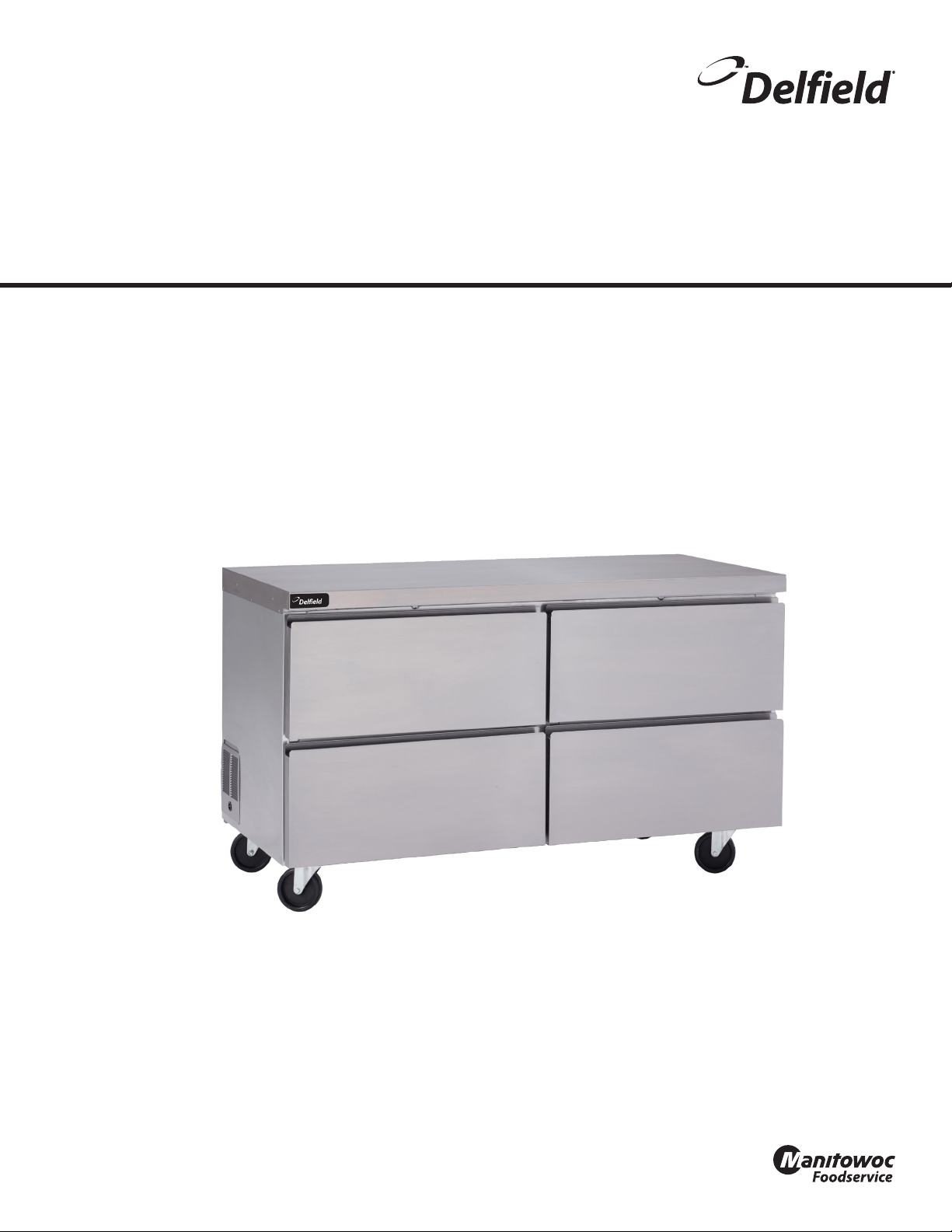
Series GU Work Tables
Original Instructions
Service Manual
English
Part Number GUC_SM 12/16
Page 2
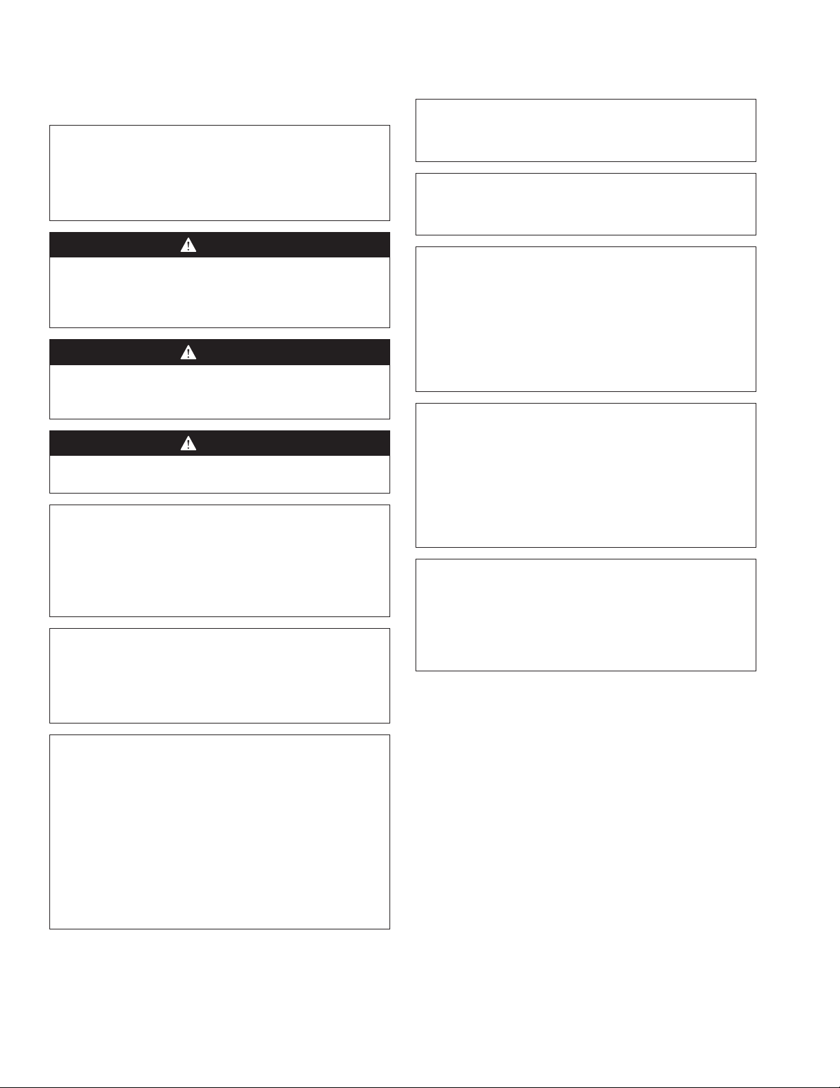
Safety Notices
Warning
n
Read this manual thoroughly before operating, installing
or performing maintenance on the equipment. Failure
to follow instructions in this manual can cause property
damage, injury or death.
DANGER
Do not install or operate equipment that has been
misused, abused, neglected, damaged, or altered/
modified from that of original manufactured
specifications.
DANGER
Keep power cord AWAY from HEATED surfaces. DO NOT
immerse power cord or plug in water. DO NOT let power
cord hang over edge of table or counter.
DANGER
All utility connections and fixtures must be maintained
in accordance with Local and national codes.
Warning
n
Authorized Service Representatives are obligated to
follow industry standard safety procedures, including,
but not limited to, local/national regulations for
disconnection / lock out / tag out procedures for all
utilities including electric, gas, water and steam.
Warning
n
Do not store or use gasoline or other flammable vapors
or liquids in the vicinity of this or any other appliance.
Never use flammable oil soaked cloths or combustible
cleaning solutions, for cleaning.
Warning
n
Do not use electrical appliances or accessories other
than those supplied by the manufacturer.
Warning
n
Use caution when handling metal surface edges of all
equipment.
Warning
n
This appliance is not intended for use by persons
(including children) with reduced physical, sensory
or mental capabilities, or lack of experience and
knowledge, unless they have been given supervision
concerning use of the appliance by a person responsible
for their safety. Do not allow children to play with this
appliance.
Caution
,
Use caution handling, moving and use of the R290
refrigerators to avoid either damaging the refrigerant
tubing or increasing the risk of a leak. Components
shall be replaced with like components. Servicing shall
be done by a factory authorized service personnel to
minimize the risk of possible ignition due to incorrect
parts or improper service.
Notice
Proper installation, care and maintenance are
essential for maximum performance and trouble-free
operation of your equipment. Visit our website www.
mtwkitchencare.com for manual updates, translations,
or contact information for service agents in your area.
Warning
n
This product contains chemicals known to the State
of California to cause cancer and/or birth defects or
other reproductive harm. Operation, installation, and
servicing of this product could expose you to airborne
particles of glasswool or ceramic fibers, crystalline
silica, and/or carbon monoxide. Inhalation of airborne
particles of glasswool or ceramic fibers is known to the
State of California to cause cancer. Inhalation of carbon
monoxide is known to the State of California to cause
birth defects or other reproductive harm.
Page 3

Table of Contents
Section 1
General Information
Section 2
Installation
Section 3
Operation
Table of Contents
Model Numbers .................................................................................................................. 5
Serial Number Information ...............................................................................................5
Warranty Information ........................................................................................................ 5
Regulatory Certifications ..................................................................................................5
Location ..............................................................................................................................7
Weight of Equipment .........................................................................................................8
Clearance Requirements ....................................................................................................8
Dimensions ......................................................................................................................... 8
Electrical Service ................................................................................................................ 9
Voltage .......................................................................................................................................................9
Fuse/Circuit Breaker ..............................................................................................................................9
Ground Fault Circuit Interrupter .......................................................................................................9
Rated Amperages, Horsepower, Voltage & Power Cord Chart ............................................ 10
Drain Connections ............................................................................................................11
Refrigeration ....................................................................................................................11
Leveling .............................................................................................................................11
Stabilizing .........................................................................................................................11
Leg & Caster Installation ..................................................................................................11
Optional Overshelf Installation Instructions .................................................................12
R290 Controls/Programming/Settings ...........................................................................13
R290 Temperature Control & Display ........................................................................................... 15
R290 Evaporator Fan Operation ..................................................................................................... 15
Changing Display from Fahrenheit to Celsius on ERC112 Control .................................... 16
Section 4
Maintenance
Cleaning and Sanitizing Procedures ...............................................................................17
General .................................................................................................................................................... 17
Interior Cleaning .................................................................................................................................. 18
Preventing Blower Coil Corrosion .................................................................................................18
Exterior Cleaning ................................................................................................................................. 18
Drain ......................................................................................................................................................... 19
Cleaning the Condenser Coil .......................................................................................................... 20
Casters ..................................................................................................................................................... 20
Doors/Hinges ........................................................................................................................................ 20
Drawer Removal For Cleaning ........................................................................................................ 20
Drawer Cleaning .................................................................................................................................. 21
Door Hinges .......................................................................................................................................... 21
Part Number GUC_SM 12/16 3
Page 4

Table of Contents (continued)
Section 5
Troubleshooting
Problem -> Cause -> Correction Chart ............................................................................23
Section 6
Controls
ERC Control Settings ........................................................................................................25
Section 7
Component Check Procedures
Drawer Horizontal Mullion Removal ..............................................................................27
Built In Guard on Rear of Unit .........................................................................................27
Evaporator Fan Access .....................................................................................................28
Temperature Probe Resistance .......................................................................................28
Frame Heater Routing ......................................................................................................29
Condenser Fan Access ......................................................................................................30
LED Light Replacement ....................................................................................................31
Section 8
Normal Operating Temperatures for Models Using Refrigerant R290
Series GU Work Table Refrigerators ................................................................................ 33
Series GU Work Table 1 Door Freezers ...........................................................................36
Series GU Work Table 2 Door Freezers ............................................................................39
Section 9
Diagrams
Standard GUR Work Table Refrigerator ..........................................................................42
GUR Work Table Refrigerator With Optional Switch ......................................................43
Standard GUF Work Table Freezer ..................................................................................44
GUF Work Table Freezer With Optional Switch .............................................................. 45
4 Part Number GUC_SM 12/16
Page 5
Section 1
General Information
Model Numbers
This manual covers the following models:
Work Top Refrigerator
Stainless Steel
Door
GUR24(B)P-S GUR24(B)P-G GUR24(B)P-D
GUR27(B)P-S GUR27(B)P-G GUR27(B)P-D
GUR32(B)P-S GUR32(B)P-G GUR32(B)P-D
GUR48(B)P-S GUR48(B)P-G GUR48(B)P-D
GUR60(B)P-S GUR60(B)P-G GUR60(B)P-D
GUR72(B)P-S GUR72(B)P-G GUR72(B)P-D
Stainless Steel Door Drawers
GUF27(B)P-S GUF27(B)P-D
GUF32(B)P-S GUF32(B)P-D
GUF48(B)P-S NA
GUF60(B)P-S GUF60(B)P-D
Glass Door Drawers
Work Top Freezer
Serial Number Information
The serial number is on the identification plate that also
includes the model number. The identification plate is
located near the top front corner of the left interior wall.
Always have the serial number of your unit available
when calling for parts or service.
Warranty Information
Visit www.delfield.com/warranty to:
• Register your product for warranty.
• Verify warranty information.
• View and download a copy of your warranty.
Regulatory Certifications
All models are certified by:
•
•
•
National Sanitation Foundation (NSF)
Underwriters Laboratories (UL)
Underwriters Laboratories of Canada (CUL)
Part Number GUC_SM 12/16 5
Page 6

General Information Section 1
THIS PAGE INTENTIONALLY LEFT BLANK
6 Part Number GUC_SM 12/16
Page 7
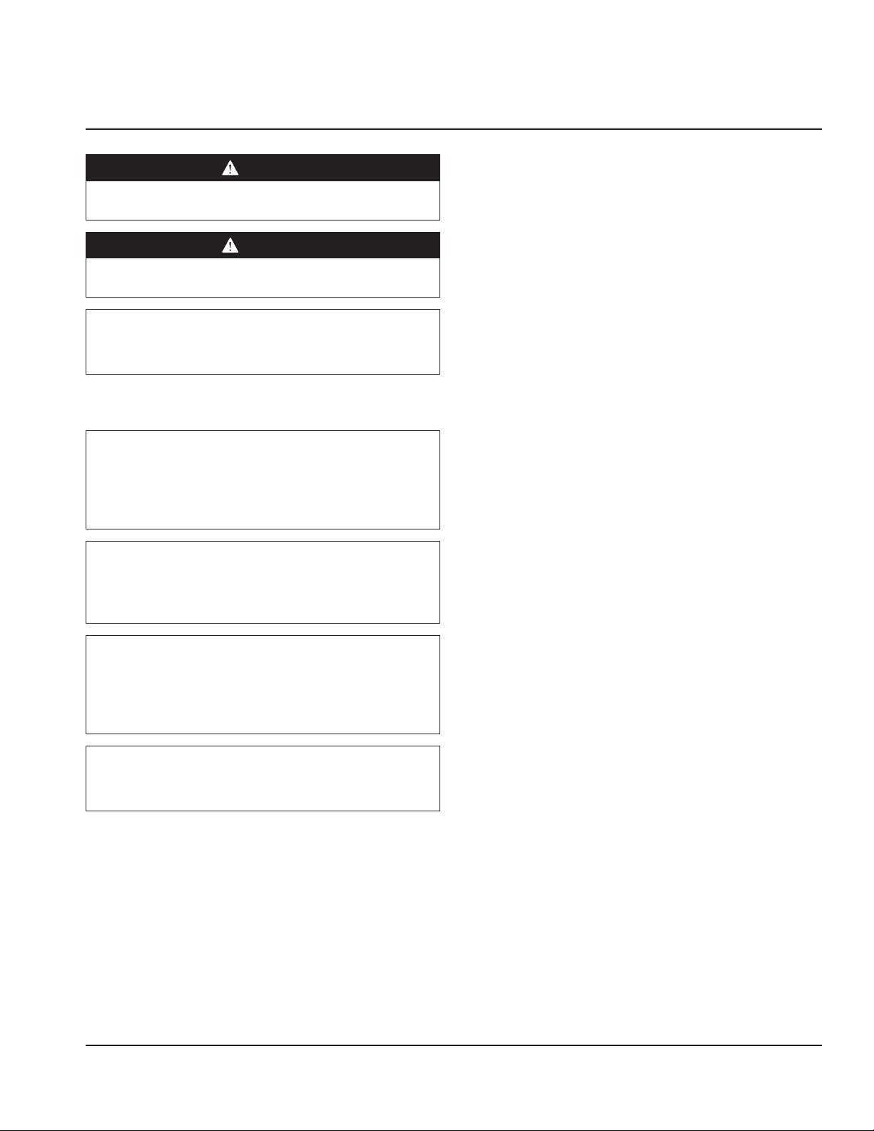
Section 2
Installation
DANGER
Installation must comply with all applicable fire and
health codes in your jurisdiction.
DANGER
Use appropriate safety equipment during installation
and servicing.
Warning
n
Do not damage the refrigeration circuit when installing,
maintaining or servicing the unit.
Location
Warning
n
This equipment must be positioned so that the plug is
accessible unless other means for disconnection from
the power supply (e.g., circuit breaker or disconnect
switch) is provided.
Warning
n
Adequate means must be provided to limit the
movement of this appliance without depending on or
transmitting stress to the electrical conduit or gas lines.
The location selected for the equipment must meet the
following criteria. If any of these criteria are not met, select
another location.
• The location MUST be level, stable and capable of
supporting the weight of the equipment.
• The location MUST be free from and clear of
combustible materials.
• Equipment MUST be level both front to back and side to
side.
• Position the equipment so it will not tip or slide.
• Front casters MUST be locked once positioned.
• Recommended air temperature is 50° - 100°F
(10° - 38°C).
• Proper air supply for ventilation is REQUIRED AND
CRITICAL for safe and efficient operation.
• Do not obstruct the flow of ventilation air. Make sure the
air vents of the equipment are not blocked.
• Do not install the equipment directly over a drain.
Steam rising up out of the drain will adversely affect
operation, air circulation, and damage electrical /
electronic components.
Warning
n
To avoid instability the installation area must be capable
of supporting the combined weight of the equipment
and product. Additionally the equipment must be level
side to side and front to back.
Warning
n
This equipment is intended for indoor use only. Do not
install or operate this equipment in outdoor areas.
Part Number GUC_SM 12/16 7
Page 8
Installation Section 2
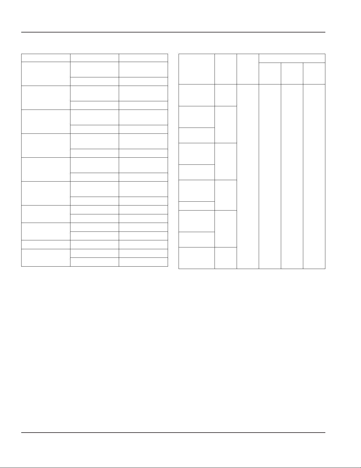
Weight of Equipment
Description Model Weight
24” Refrigerator
27” Refrigerator
32” Refrigerator
48” Refrigerator
60” Refrigerator
72” Refrigerator
27” Freezer
32” Freezer
48” Freezer
60” Freezer
GUR24(B)P-S,
GUR24(B)P-G
GUR24(B)P-D
GUR27(B)P-S,
GUR27(B)P-G
GUR27(B)P-D
GUR32(B)P-S,
GUR32(B)P-G
GUR32(B)P-D
GUR48(B)P-S,
GUR48(B)P-G
GUR48(B)P-D
GUR60(B)P-S,
GUR60(B)P-G
GUR60(B)P-D
GUR72(B)P-S,
GUR72(B)P-G
GUR72(B)P-D
GUF27(B)P-S
GUF27(B)P-D
GUF32(B)P-S
GUF32(B)P-D
GUF48(B)P-S
GUF60(B)P-S
GUF60(B)P-D
140 lbs ( 64kg)
162 lbs ( 73kg)
145 lbs ( 66kg)
168 lbs ( 76kg)
161 lbs ( 73kg)
185 lbs ( 84kg)
207 lbs ( 94kg)
252 lbs ( 114kg)
234 lbs ( 106kg)
284 lbs ( 129kg)
263 lbs ( 119kg)
330 lbs ( 150kg)
151 lbs ( 68kg)
175lbs ( 79kg)
165 lbs ( 75kg)
189 lbs ( 86kg)
224 lbs ( 102kg)
250 lbs ( 113kg)
300 lbs ( 136kg)
Clearance Requirements
• Keep the vents clean and free of obstruction.
• Casters or optional legs must be used and not removed.
Dimensions
Work Height with
Models Length Depth
GUR24(B)P-S,
GUR24(B)P-G,
GUR24(B)P-D
GUR27(B)P-S,
GUR27(B)P-G,
GUR27(B)P-D
GUF27(B)P-S,
GUF27(B)P-D
GUR32(B)P-S,
GUR32(B)P-G,
GUR32(B)P-D
GUF32(B)P-S,
GUF32(B)P-D
GUR48(B)P-S,
GUR48(B)P-G,
GUR48(B)P-D
GUF48(B)P-S
GUR60(B)P-S,
GUR60(B)P-G,
GUR60(B)P-D
GUF60(B)P-S,
GUF60(B)P-D
GUR72(B)P-S,
GUR72(B)P-G,
GUR72(B)P-D
24.00”
(61cm)
27.00”
(69cm)
32.00”
(81cm)
48.00”
(122cm)
60.00”
(152cm)
72.00”
(183cm)
31.50”
(80cm)
5”
Casters
or Feet
36.00“
(91cm)
Units with a backsplash have a B in the model number. The
backsplash doesn’t change the work height but adds 4.00”
(10cm) to the overall height.
3”
Casters
33.88“
(86cm)
2”
Casters
31.88“
(81cm)
8 Part Number GUC_SM 12/16
Page 9
Section 2 Installation
Work Top with Door Models
Refrigerator Freezer Volume
3
GUR24(B)P-S,
GUR24(B)P-G
GUR27(B)P-S,
GUR27(B)P-G
GUR32(B)P-S,
GUR32(B)P-G
GUR48(B)P-S,
GUR48(B)P-G
GUR60(B)P-S,
GUR60(B)P-G
GUR72(B)P-S,
GUR72(B)P-G
Work Top with Drawers Models
Refrigerator Freezer Quantity of
GUR24(B)P-D NA 8
GUR27(B)P-D GUF27(B)P-D 12
GUR32(B)P-D GUF32(B)P-D 12
GUR48(B)P-D NA 16
GUR60(B)P-D GUF60(B)P-D 24
GUR72(B)P-D NA 24
NA 4.1 ft
GUF27(B)P-S 4.8 ft
GUF32(B)P-S 5.8 ft
GUF48(B)P-S 9.2 ft
GUF60(B)P-S 11.7 ft
NA 14.2 ft
1/6 Size x 6” Deep
(116 L)
3
(136 L)
3
(164 L)
3
(261 L)
3
(331 L)
3
(402 L)
Pans
Electrical Service
DANGER
Check all wiring connections, including factory
terminals, before operation. Connections can become
loose during shipment and installation.
Warning
n
This appliance must be grounded and all field wiring
must conform to all applicable local and national
codes. Refer to rating plate for proper voltage. It is the
responsibility of the end user to provide the disconnect
means to satisfy the authority having jurisdiction.
VOLTAGE
All electrical work, including wire routing and grounding,
must conform to local, state and national electrical codes.
The following precautions must be observed:
• The equipment must be grounded.
• A separate fuse/circuit breaker must be provided for
each unit.
• Check all green ground screws, cables and wire
connections to verify they are tight before start-up.
FUSE/CIRCUIT BREAKER
A separate fuse/circuit breaker must be provided for each
unit.
GROUND FAULT CIRCUIT INTERRUPTER
Ground Fault Circuit Interrupter (GFCI/GFI) protection is
a system that shuts down the electric circuit (opens it)
when it senses an unexpected loss of power, presumably
to ground. Manitowoc does not recommend the use of
GFCI/GFI circuit protection to energize our equipment.
If code requires the use of a GFCI/GFI then you must
follow the local code. The circuit must be dedicated, sized
properly and there must be a panel GFCI/GFI breaker. We
do not recommend the use of GFCI/GFI outlets to energize
our equipment as they are known for more intermittent
nuisance trips than panel breakers.
Part Number GUC_SM 12/16 9
Page 10
Installation Section 2
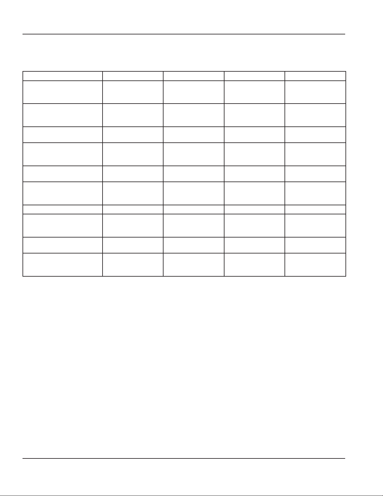
RATED AMPERAGES, HORSEPOWER, VOLTAGE &
POWER CORD CHART
Maximum 8ft (2.4m) cord with plug.
Model Amps HP Voltage, Cycle, Phase NEMA Plug
GUR24(B)P-S,
GUR24(B)P-G,
GUR24(B)P-D
GUR27(B)P-S,
GUR27(B)P-G,
GUR27(B)P-D
GUF27(B)P-S,
GUF27(B)P-D
GUR32(B)P-S,
GUR32(B)P-G,
GUR32(B)P-D
GUF32(B)P-S,
GUF32(B)P-D
GUR48(B)P-S,
GUR48(B)P-G,
GUR48(B)P-D
GUF48(B)P-S 6.4 1/3 115V, 60Hz, 1Ph 5-15P
GUR60(B)P-S,
GUR60(B)P-G,
GUR60(B)P-D
GUF60(B)P-S,
GUF60(B)P-D
GUR72(B)P-S,
GUR72(B)P-G,
GUR72(B)P-D
3.2 1/5 115V, 60Hz, 1Ph 5-15P
3.2 1/5 115V, 60Hz, 1Ph 5-15P
2.6 1/4 115V, 60Hz, 1Ph 5-15P
3.2 1/5 115V, 60Hz, 1Ph 5-15P
2.6 1/4 115V, 60Hz, 1Ph 5-15P
3.2 1/5 115V, 60Hz, 1Ph 5-15P
3.2 1/5 115V, 60Hz, 1Ph 5-15P
6.4 1/3 115V, 60Hz, 1Ph 5-15P
3.2 1/5 115V, 60Hz, 1Ph 5-15P
10 Part Number GUC_SM 12/16
Page 11
Section 2 Installation
Drain Connections
Warning
n
Moisture collecting from improper drainage can create a
slippery surface on the floor and a hazard to employees.
It is the owner’s responsibility to provide a container or
outlet for drainage.
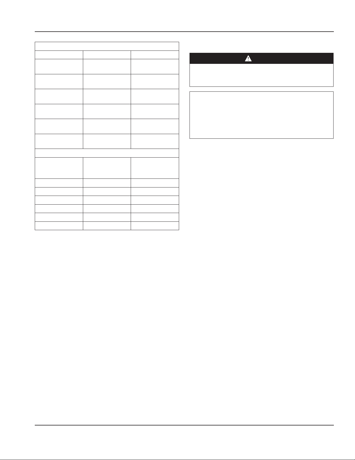
Refrigeration
Model BTU/Hour
Capacity
GUR24(B)P-S 270 147 78
GUR24(B)P-G 300 185 78
GUR24(B)P-D 320 173 78
GUR27(B)P-S 280 157 78
GUR27(B)P-G 330 195 78
GUR27(B)P-D 320 186 78
GUF27(B)P-S 400 291 62
GUF27(B)P-D 560 410 62
GUR32(B)P-S 310 172 78
GUR32(B)P-G 360 210 78
GUR32(B)P-D 360 208 78
GUF32(B)P-S 450 325 62
GUF32(B)P-D 640 466 62
GUR48(B)P-S 470 270 78
GUR48(B)P-G 560 346 78
GUR48(B)P-D 560 325 78
GUF48(B)P-S 680 479 111
GUR60(B)P-S 530 307 78
GUR60(B)P-G 630 383 78
GUR60(B)P-D 630 377 78
GUF60(B)P-S 790 559 111
GUF60(B)P-D 1140 831 111
GUR72(B)P-S 630 365 78
GUR72(B)P-G 780 479 78
GUR72(B)P-D 740 449 78
Heat of
Rejection
Charge
Leveling
After the cabinet has been placed in the desired location,
cabinets with legs must be leveled. Level units from front to
back and from side to side. Leveling will insure proper door
operation and removal of condensate. Cabinets with casters
must have the caster brake set so the cabinet cannot move.
Stabilizing
It is very important that all legs are properly adjusted to
keep the cabinet level, evenly distribute the weight and to
make sure the unit will not rock, lean or be unstable.
Leg & Caster Installation
DANGER
Legs or casters must be installed and the legs or casters
must be screwed in completely to prevent bending.
When casters are installed the mass of this unit will
allow it to move uncontrolled on an inclined surface.
These units must be tethered/secured to comply with
all applicable codes.
Warning
n
The unit must be installed in a stable condition with
the front wheels locked. Locking the front casters after
installation is the owner’s and operator’s responsibility.
Warning
n
Use a jack to lift the refrigeration unit off the ground
just far enough to remove the leg/caster. Place blocking
underneath the unit. Do not work underneath a raised
unit without proper blocking. Do not lift the unit more
than necessary to remove the leg/caster. Lifting the unit
too far can make the unit unstable.
Caution
,
All single-section units require that the swivel casters be
mounted on the front and rigid casters be mounted on
the rear.
Part Number GUC_SM 12/16 11
Page 12
Installation Section 2
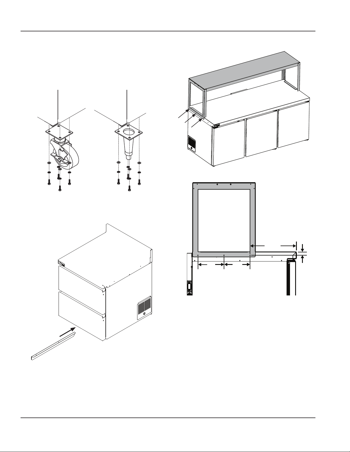
To install the legs or casters:
1. Remove unit from skid.
2. Raise unit to access leg/caster mounting holes on
bottom of unit.
3. Attach the legs or casters to bottom of cabinet using
hex head bolts.
4. This last step applies only to single section units with 2”
casters. While the unit is raised, mount an air divider on
the bottom. It runs front to back down the center and
has two holes for mounting.
Optional Overshelf Installation Instructions
13.33“
(34cm)
7.50“
(19cm)
7.50“
(19cm)
1.00“
(2.5cm)
If the unit is ordered to have the overshelf:
1. Remove the three screws from each top side of the
cabinet (total six screws).
2. Set the overshelf in-place on the top of the cabinet.
3. Line up the three overshelf holes with the unit holes.
4. Secure with three screws per side of the cabinet (total
six screws).
If the overshelf was not ordered with the unit:
1. Set the overshelf in-place on the top of the cabinet.
2. Secure with three screws per side of the cabinet (total
six screws).
12 Part Number GUC_SM 12/16
Page 13
Section 3
Operation
DANGER
Do not operate any appliance with a damaged cord
or plug. All repairs must be performed by a qualified
service company.
DANGER
Never stand on the unit! They are not designed to
hold the weight of an adult, and may collapse or tip if
misused in this manner.
Warning
n
Do not contact moving parts.
Warning
n
All covers and access panels must be in place and
properly secured, before operating this equipment.
Warning
n
Do not use electrical appliances inside the food storage
compartment of this appliance.
Warning
n
The operator of this equipment is solely responsible
for ensuring safe holding temperature levels for all
food items. Failure to do so could result in unsafe food
products for customers.
Warning
n
Overloading shelves can damage equipment or cause
bodily injury.
Warning
n
Damp or wet hands may stick to cold surfaces.
Caution
,
Do not block the supply and return air grills or the air
space around the air grills. Keep plastic wrappings,
paper, labels, etc. from being airborne and lodging in
the grills. Failure to keep the air grills clear will result in
unsatisfactory operation of the system.
Caution
,
Do not throw items into the storage area. Failure to
heed this recommendation could result in damage to
the interior of the cabinet or to the blower coil.
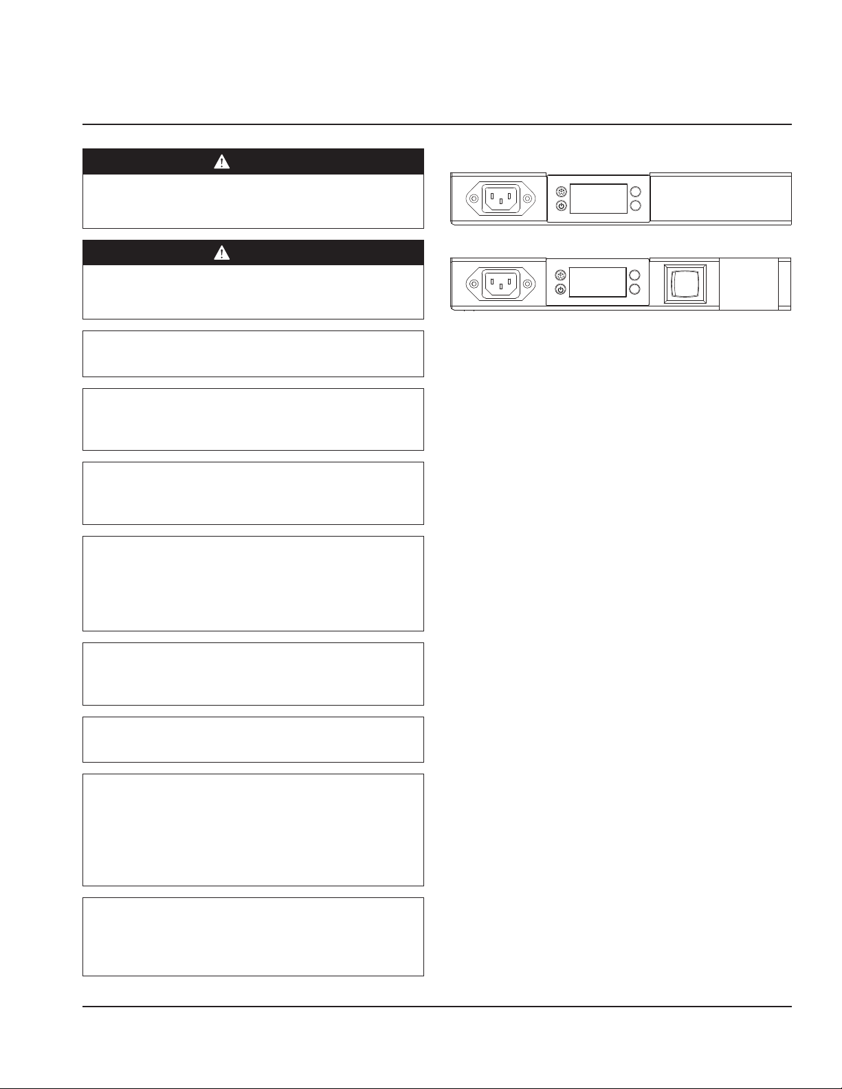
R290 Controls/Programming/Settings
V
V
Standard Control Panel
V
V
Freezer Control Panel With Optional Power Switch
R290 Refrigerator
Refrigerators are factory set at mid-range to maintain about
38ºF (3ºC) box temperature.
1. At initial start-up or anytime power is disconnected,
then reconnected to the unit, the control will go into
defrost mode.
2. The control will enter a DEFROST mode and the display
will read dEF. The compressor and condenser fan as
well as the evaporator fan will remain off until this
initial defrost is complete. This initial defrost cycle may
take up to 35 minutes to complete.
3. The display will continue to read dEF for an additional
30 minutes while the cooling cycle cools the box to the
set temperature.
4. Then the digital thermostat will display box
temperature.
5. The temperature control will cycle the compressor,
evaporator fan motor and condenser fan motor to
maintain box temperature at the control setting. For
more information see “R290 Evaporator Fan Operation”
on page 15.
R290 Refrigerator Defrost
The temperature control also monitors the evaporator
temperature and will turn off the compressor and
condenser fan motor when needed to allow accumulated
frost on the evaporator to clear. During this defrost cycle,
the digital temperature display will read dEF. After the
defrost cycle is complete, the temperature control will
return to a normal cooling cycle, but the display will
continue to read dEF until the evaporator returns to normal
cooling temperatures (up to 30 minutes).
Part Number GUC_SM 12/16 13
Page 14

Operation Section 3
R290 Freezer
Freezers are factory set at mid-range to maintain about -3ºF
(-19ºC) box temperature.
1. At initial start-up or anytime power is disconnected,
then reconnected to the unit, the control will go into
defrost mode
2. The control will enter a DEFROST mode and the display
will read dEF. The compressor and condenser fan as
well as the evaporator fan will remain off until this
initial defrost is complete. This initial defrost cycle may
take up to 35 minutes to complete.
3. The display will continue to read dEF for an additional
30 minutes while the freezing cycle cools the box to the
set temperature.
4. Then the thermostat will display box temperature.
5. The temperature control will cycle the compressor,
evaporator fan motor and condenser fan motor to
maintain box temperature at the control setting. For
more information see “R290 Evaporator Fan Operation”
on page 15.
R290 Freezer Automatic Defrost
The control also monitors compressor total running time
and will enter a defrost cycle after total compressor running
time is greater than seven hours since the last defrost cycle
OR if evaporator coil temperature drops below -30ºF (-34ºC)
(indicating excessive frost on the coil).
R290 Freezer Manual Defrost
If a manual defrost is desired, hold the upper left button for
five seconds or unplug the unit for several seconds, then
plug unit back in. This will cause the control to re-initialize
and then enter a defrost cycle.
When the control enters the defrost mode, it switches off
the evaporator fan motor, compressor and condenser fan
motor, and switches on the defrost heater to warm the
evaporator coil. Thereby melting all frost accumulated
during the previous refrigeration cycle. The digital
temperature display will now read dEF. The control will
continue the defrost cycle for a MINIMUM of six minutes
and a MAXIMUM of 35 minutes depending on the amount
of frost accumulated on the evaporator coil.
After the defrost cycle is complete, the control returns
to a normal refrigeration cycle, however the evaporator
fan motor will not switch on until the evaporator reaches
-5°F (-21°C) or two minutes AFTER the compressor and
condenser fan motor have begun operating. The digital
temperature display will continue to read dEF until the
evaporator has returned to normal freezing temperatures
(up to 30 minutes).
14 Part Number GUC_SM 12/16
Page 15
Section 3 Operation
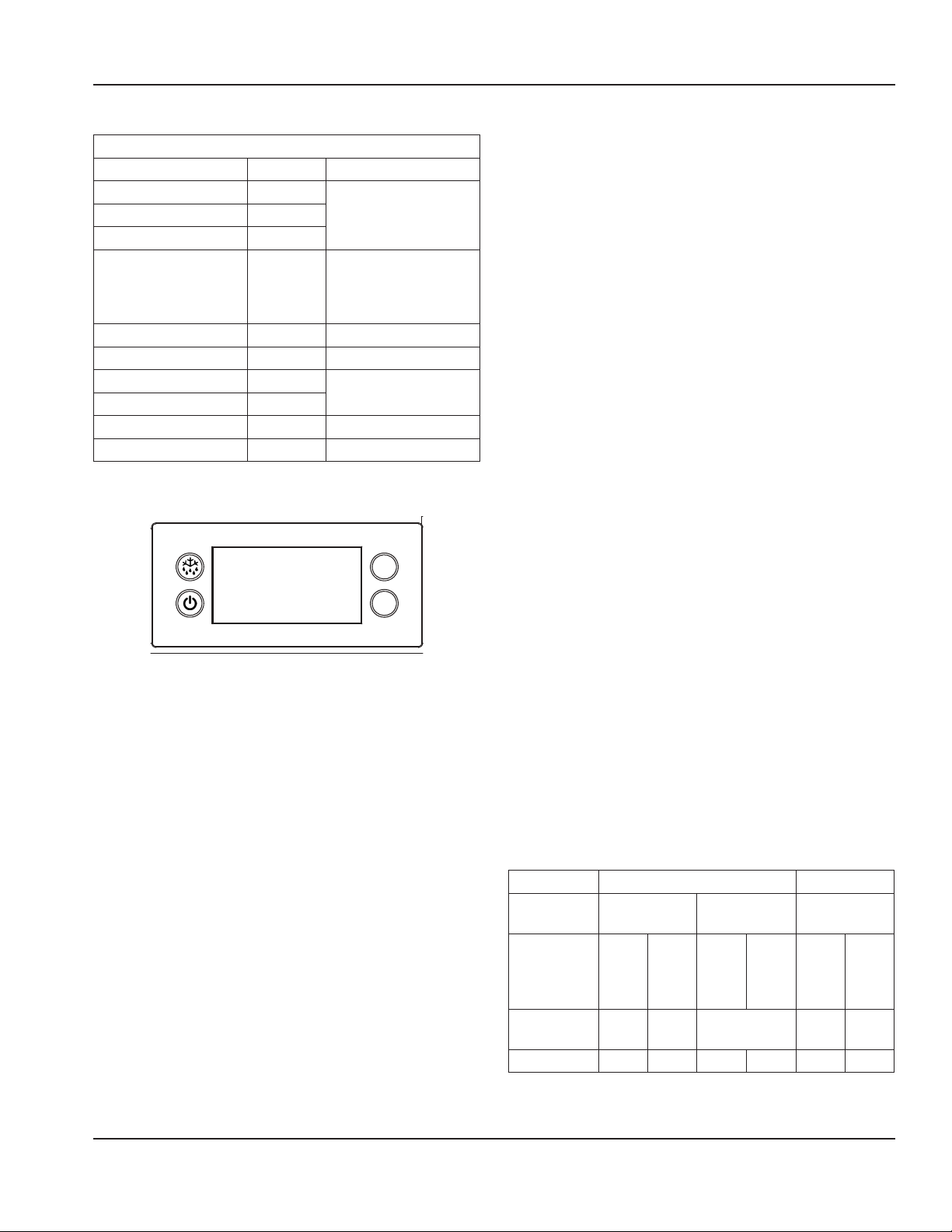
R290 TEMPERATURE CONTROL & DISPLAY
Operation / Indication
Status Displayed Comments
Normal (°C) Temp. [°C] Unit depends on setting
Normal (°F) Temp. [°F]
Show set-point Temp.
Set to Defrost dEF / Temp Depends on setting
Sensor 1 defect E01 Air sensor
Sensor 2 defect E02 Coil sensor
High temperature alarm Hi Automatically switching
Low temperature alarm Lo
Line voltage too hight uHi
Line voltage too low uLi
(parameters in control)
(parameters in control
or as chosen by upper
left button)
at 2 sec rate
R290 Temperature Control & Display Operation
V
V
R290 Power Switch
Select units are equipped with a power disconnect switch
located behind the louvered panel. Switch must be in the
on position for the unit to operate. If the switch is turned
off, then returned to the on position, the unit will enter a
defrost cycle and the display will read dEF.
R290 Energy Saver Switch
Select freezers are equipped with an energy saver switch
for service use. It is a rocker switch located behind the
mechanical raceway that controls the amount of heat
applied to the door perimeter. The normal operating
position for this switch is the on position, providing the
least heat. If excessive condensation is observed on the
door opening, switch to the off position with the help of an
authorized service agent. The off position will increase the
heat.
R290 Temperature Alarm
The alarm will flash “HI” or “LO” 90 minutes after the unit
has reached its alarm temperature point or after any
power interruption if the temperature is above or below
the alarm set points. Refrigerators are factory set at midrange to maintain about 38ºF (3ºC) box temperature. The
high refrigerator temperature point is 50°F (10°C). The low
refrigerator temperature point is 25°F (-4°C). Freezers are
factory set at mid-range to maintain about -3ºF (-19ºC) box
temperature. The high freezer temperature point is 20°F
(-7°C). Freezers do not have a low temperature point.
Press upper or lower right button.
• Display show actual set-point (blinking).
• If buttons untouched for 3 seconds returns to
normal.
• Increase set-point by pressing upper button. Max value
depends on parameters in control.
• Decrease set-point by pressing lower button. Min value
depends on parameters in control.
• If buttons untouched for 3 seconds returns to
normal and stores new set-point.
Press upper left button for 5 seconds.
• Start defrost.
Press lower left button for 5 seconds.
• Unit goes into stand-by mode.
• The display will read off, then a period.
• Press the lower left button again for 5 seconds.
• The display will read on.
• The unit will then start up in the defrost mode,
and display will read dEF.
R290 EVAPORATOR FAN OPERATION
During normal operation the evaporator fan may cycle
and/or pulse independently of the compressor. Consult
Technical Support at 1-844-724-CARE if you are unsure of
the proper function.
Cooling Cycle Defrost Cycle
Compressor OnCompressor
Off
Off
Evap Fan OnEvap Fan
Refrigerator X Cycles On 2-Min,
Freezer X X X
On
Evap Fan
Off 2-Min
Off
Evap Fan
Compressor
Off
Evap Fan OnEvap Fan
X
Off
Part Number GUC_SM 12/16 15
Page 16

Operation Section 3
CHANGING DISPLAY FROM FAHRENHEIT TO CELSIUS
ON ERC112 CONTROL
1. Simultaneously hold the up and down arrows for
5 seconds to access menu for password protected
parameters.
2. Screen should temporarily flash PAS and then move to
a numeric screen.
3. Scroll to 187 using the up/down arrows and push the
stand-by button (lower left button) to enter.
6. -F should be displayed indicating Fahrenheit. Use
the down arrow to change it to -C for Celsius and hit
the stand-by button (lower left button) to enter the
change.
7. Push the defrost button (upper left button) to move
out of the display unit menu.
4. Scroll to dis using the up/down arrows and push the
stand-by button (lower left button) to enter into the
display menu.
5. Scroll to CFu using the up/down arrows and push the
stand-by button (lower left button) to enter the display
unit menu.
8. Push the defrost button (upper left button) to move
out of the display menu and back to the normal display.
NOTE: For steps 7 and 8, display will return back to normal
display after 30 seconds of inactivity.
16 Part Number GUC_SM 12/16
Page 17

Section 4
Maintenance
DANGER
It is the responsibility of the equipment owner to
perform a Personal Protective Equipment Hazard
Assessment to ensure adequate protection during
maintenance procedures.
DANGER
Failure to disconnect the power at the main power
supply disconnect could result in serious injury or death.
The power switch DOES NOT disconnect all incoming
power.
DANGER
Disconnect electric power at the main power disconnect
for all equipment being serviced. Observe correct
polarity of incoming line voltage. Incorrect polarity can
lead to erratic operation.
Warning
n
Never use sharp objects or tools to remove ice or frost.
Do not use mechanical devices or other means to
accelerate the defrosting process.
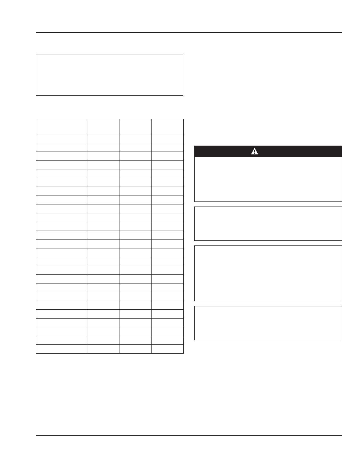
Cleaning and Sanitizing Procedures
Caution
,
Maintenance and servicing work other than cleaning as
described in this manual must be done by an authorized
service personnel.
GENERAL
Warning
n
When using cleaning fluids or chemicals, rubber gloves
and eye protection (and/or face shield) must be worn.
Owners and operators are responsible for maintaining
the equipment in accordance with the instructions in this
manual. Maintenance procedures are not covered by the
warranty.
Maintenance Daily Weekly Monthly
Interior X X X
Gasket X X X
Exterior X X X
Drain X X X
Condenser Coil X X X
Casters X X X
Part Number GUC_SM 12/16 17
After Prolonged
Shutdown
At Start-Up
Page 18

Maintenance Section 4
INTERIOR CLEANING
Notice
When cleaning interior and exterior of unit, care should
be taken to avoid the front power switch and the rear
power cord. Keep water and/or cleaning solutions away
from these parts.
Notice
Never use a high-pressure water jet for cleaning or hose
down or flood interior or exterior of units with water. Do
not use power cleaning equipment, steel wool, scrapers
or wire brushes on stainless steel or painted surfaces.
The interior can be cleaned using soap and warm water. If
this isn’t sufficient, try ammonia and water or a nonabrasive
liquid cleaner.
PREVENTING BLOWER COIL CORROSION
To help prevent corrosion of the blower coil, store all acidic
items, such as pickles and tomatoes, in seal-able containers.
Immediately wipe up all spills.
EXTERIOR CLEANING
Notice
Never use an acid based cleaning solution on exterior
panels! Many food products have an acidic content,
which can deteriorate the finish. Be sure to clean the
stainless steel surfaces of ALL food products.
Clean the area around the unit as often as necessary to
maintain cleanliness and efficient operation.
Wipe gasket and surfaces with a damp cloth rinsed in water
to remove dust and dirt from the outside of the unit. Always
rub with the “grain” of the stainless steel to avoid marring
the finish. If a greasy residue persists, use a damp cloth
rinsed in a mild dish soap and water solution. Wipe dry with
a clean, soft cloth.
Never use steel wool or abrasive pads for cleaning. Never
use chlorinated, citrus based or abrasive cleaners.
Stainless steel exterior panels have a clear coating that
is stain resistant and easy to clean. Products containing
abrasives will damage the coating and scratch the panels.
Daily cleaning may be followed by an application of
stainless steel cleaner which will eliminate water spotting
and fingerprints. Early signs of stainless steel breakdown
are small pits and cracks. If this has begun, clean thoroughly
and start to apply stainless steel cleaners in attempt to
restore the steel.
18 Part Number GUC_SM 12/16
Page 19

Section 4 Maintenance
DRAIN
Each unit has a drain located inside the unit that removes
the condensation from the evaporator coil and routes it
to an external condensate evaporator pan. Each drain can
become loose or disconnected during normal use.
• The leveling of the unit is important as the units are
designed to drain properly when level.
• If you notice water accumulation on the inside of
the unit, be sure the drain tube is connected to the
evaporator drain pan.
• If water is collecting underneath the unit, make sure the
end of the drain tube is in the condensate evaporator.
Cleaning Instructions
1. Inside the unit under the evaporator assembly locate
the drain pan and drain.
Drain On One Section Door Unit
2. Locate the drain tube in the condensing unit.
Drain Tube In The Condensing Unit
3. Verify the drain tube is connected to the evaporator
drain pan.
4. Verify the end of the drain tube is in the condensate
evaporator.
5. Be sure the drain line is free of obstructions.
Drain On Two Section Drawer Unit
Drain Pan Line Drawing
Part Number GUC_SM 12/16 19
Page 20

Maintenance Section 4
CLEANING THE CONDENSER COIL
In order to maintain proper refrigeration performance, the
condenser fins must be cleaned of dust, dirt and grease
regularly. It is recommended that this be done monthly. If
conditions are such that the condenser is totally blocked
in a month, the frequency of cleaning should be increased.
Clean the condenser with a vacuum cleaner or stiff brush. If
extremely dirty, a commercially available condenser cleaner
may be required.
Failure to maintain a clean condenser coil can initially cause
high temperatures and excessive run times. Continuous
operation with a dirty or clogged condenser coil can
result in compressor failure. Neglecting the condenser coil
cleaning procedures will void any warranties associated
with the compressor and cost to replace the compressor.
CASTERS
Wipe casters with a damp cloth monthly to prevent
corrosion.
DOORS/HINGES
Over time and with heavy-use doors, the hinges may
become loose. If this happens, tighten the screws that
mount the hinge brackets to the frame of the unit. Loose
or sagging doors can cause the hinges to pull out of the
frame, which may damage both the doors and the hinges.
In some cases this may require qualified service agents or
maintenance personnel to perform repairs.
DRAWER REMOVAL FOR CLEANING
1. Pull drawer out until it hits a stop.
2. Pull white clip forward to release drawer from track.
3. Lift and remove drawer.
4. Pull intermediate tracks out until they hit a stop.
5. Locate gray safety clips on each drawer track. Push
each gray safety clip until it clicks, releasing each
intermediate track.
6. Remove intermediate tracks.
20 Part Number GUC_SM 12/16
Page 21

Section 4 Maintenance
DRAWER CLEANING
Drawers and tracks should be cleaned on a weekly basis.
The cleaner the tracks are the better they will operate.
• The drawer tracks are dishwasher safe or can be cleaned
in a sink with detergents and a soft bristle brush. Using a
soft bristle brush, wash the track making sure each roller
is thoroughly cleaned.
• The drawer cage should be cleaned with a soft bristle
brush, removing any food and debris gathered on the
bottom ledge. Once it’s cleaned thoroughly with a soft
bristle brush, wipe remaining debris clean with a soft
towel.
Drawer Reassembly
1. Push the intermediate tracks back into the drawer cage.
2. Press the gray plastic safety clip and finish installing the
intermediate tracks.
3. Push the drawer back in slowly. It will hit a stop. Lift the
front of the drawer up and continue inward.
4. Pull the drawer back out.
5. Locate the white clips on either side of the drawer.
Press them down and in to lock.
DOOR HINGES
1. With a 3/8” nut driver remove the nuts and bottom
hinge from the unit.
2. Remove door from unit.
3. Remove two screws from the bottom of the door to
replace the hinge cartridge.
Part Number GUC_SM 12/16 21
Page 22

Maintenance Section 4
4. Place a white spacer on the bottom hinge pin.
5. Place the hinge on the hinge pin, rotate it and ensure
there is tension in both directions.
6. Rotate the door hinge 160°-180°.
7. Hold the hinge, twist the door and slide the top pin into
the top hinge.
8. Screw the bottom hinge to the unit.
9. Check the door alignment. Check that it shuts and
seals. Adjust the bottom hinge if necessary.
22 Part Number GUC_SM 12/16
Page 23

Section 5
Troubleshooting
Problem -> Cause -> Correction Chart
Problem Cause Correction
Cabinet not running Fuse blown or circuit breaker tripped. Replace fuse or reset circuit breaker.
Power cord unplugged. Plug power cord into unit and into outlet.
Thermostat set too high. Set thermostat to lower temperature.
Main power switch turned off. Turn main power switch on.
Cabinet in defrost cycle.
(Freezer models)
Condensing unit runs
for long periods or
continuously
Cabinet temperature is
too high
Cabinet is noisy Loose part(s). Locate and tighten loose part(s).
Refrigerator is freezing
product
Compressor will not
start
Excessive amount of warm product placed in
cabinet.
Prolonged door openings or door(s) ajar. Make sure door(s) are closed when not in use. Avoid
Door gasket(s) not sealing properly. Check gasket condition. Adjust door or replace gasket if
Dirty condenser coil. Clean the condenser coil.
Evaporator coil iced over. Turn unit off and allow coil to defrost.
Thermostat set too high. Set thermostat to lower temperature.
Poor air circulation in cabinet. Re-arrange product to allow proper air circulation.
Exterior thermometer is out of calibration. Re-calibrate thermometer.
Excessive amount of warm product placed in
cabinet.
Prolonged door openings or door(s) ajar. Make sure door(s) are closed when not in use.
Dirty condenser coil. Clean the condenser coil.
Evaporator coil iced over. Turn unit off and allow coil to defrost.
Thermostat is set too low. Set thermostat to higher temperature.
Dirty condenser coil. Clean the condenser coil.
Not enough cabinet clearance for proper
refrigeration system operation.
Low voltage to cabinet. Check and correct incoming voltage to cabinet.
Allow adequate time for product to cool down.
Allow adequate time for product to cool down.
Move cabinet or make other adjustments to gain proper
Wait for defrost cycle to finish.
prolonged door openings.
necessary.
Make sure thermostat is not set too cold.
Also, check gasket condition.
Avoid prolonged door openings.
Make sure thermostat is not set too cold.
Also, check gasket condition.
cabinet clearances.
Part Number GUC_SM 12/16 23
Page 24

Troubleshooting Section 5
THIS PAGE INTENTIONALLY LEFT BLANK
24 Part Number GUC_SM 12/16
Page 25

Section 6
Controls
ERC Control Settings
ERC Password Protection
Parameter
Setpoint SEt Desired Temperature 187
Defrost On Compressor Runtime dCt Real Time or Compressor Running Time Triggers Defrost 187
Display Unit CFu Fahrenheit or Celsius 187
High Alarm HAt Alarm Sounds Upon Reaching This High Temperature 187
Low Alarm LAt Alarm Sounds Upon Reaching This Low Temperature 187
High Alarm Delay Htd Time Delay Prior To Alarming Once High Temperature Alarm
Low Alarm Delay Ltd Time Delay Prior To Alarming Once Low Temperature Alarm
Accumulated Compressor Runtime ACt Total Compressor Runtime Since Manufactured Date 187
Accumulated Evaporator Fan Runtime AFt Total Evaporator Fan Runtime Since Manufactured Date 187
Accumulated ERC Runtime AEt Total ERC Runtime Since Manufactured Date 187
Compressor Relay Counter rL1 Total Compressor Cycles Since Manufactured Date 187
Evaporator Fan Relay Counter rL3 Total Evaporator Fan Cycles Since Manufactured Date 187
Defrost Relay Counter rL2 Total Defrost Cycles Since Manufactured Date 187
Defrost Time Counter dnt Total Defrost Time Since Manufactured Date 187
Evaporator Temperature Et1 Real Time Evaporator Outlet Temperature 187
Cabinet Temperature att Real Time Cabinet Air Temperature 187
Danfoss
Acronym
Description Password
Is Reached
Is Reached
187
187
Part Number GUC_SM 12/16 25
Page 26

Controls Section 6
THIS PAGE INTENTIONALLY LEFT BLANK
26 Part Number GUC_SM 12/16
Page 27

Section 7
Component Check Procedures
Drawer Horizontal Mullion Removal
1. Pull drawer out until it hits a stop.
2. Pull white clip forward to release drawer from track.
3. Lift and remove drawer.
Built In Guard on Rear of Unit
Ensure built in guard on rear of unit is in place. It will protect
the control in case of a refrigerant leak.
4. Remove the four 5/16 hex head screws securing the
horizontal mullion between the two drawers.
One Bottom and One Top Horizontal Mullion Screw
Part Number GUC_SM 12/16 27
Page 28

Component Check Procedures Section 7
Evaporator Fan Access Temperature Probe Resistance
Acceptable range in 32°F water is 15,000-17,000 ohms.
Defrost Probe Resistance, Delfield Part Number 2194755
Temperature in
Fahrenheit
0 -17.8 42,837
5 -15.0 36,503
10 -12.2 31,258
15 -9.4 26,784
20 -6.7 23,097
25 -3.9 19,960
30 -1.1 17,275
35 1.7 15,007
40 4.4 13,065
45 7.2 11,371
50 10.0 9,951
Temperature in
Celsius
Resistance in
Ohms
Air Probe Resistance, Delfield Part Number 2194756
Temperature in
Fahrenheit
0 -17.8 43,297
5 -15.0 36,503
10 -12.2 30,884
15 -9.4 26,948
20 -6.7 22,928
25 -3.9 20,082
30 -1.1 17,188
35 1.7 14,751
40 4.4 13,019
45 7.2 11,506
50 10.0 9,951
Temperature in
Celsius
Resistance in
Ohms
28 Part Number GUC_SM 12/16
Page 29

Section 7 Component Check Procedures
Frame Heater Routing
60” Drawer Unit
27” or 32” Door Unit
27” or 32” Drawer Unit
48” or 60” Door Unit
60” Door-Drawer Unit
60” Drawer-Door Unit
Part Number GUC_SM 12/16 29
Page 30

Component Check Procedures Section 7
Condenser Fan Access
1. Remove the back panel.
3. Pull out the condensing unit.
4. Unscrew the fan assembly from the condensing coil.
5. Adjust the assembly to access the fan blade.
2. Remove two screws from each side of the condensing
unit. It may also be necessary to remove the filter
bracket next to the condenser coil.
30 Part Number GUC_SM 12/16
Page 31

Section 7 Component Check Procedures
LED Light Replacement
Important Notes
• Tools Required: T6 Torx Bit & Phillips Head screwdriver
• Keep track of the light cover, all screws and wires.
They will be reused.
Removal
1. Unscrew the light fixture from the unit.
Two (2) Screws Secure the Light in the Unit
2. Unscrew the light from the cover with the T6 torx bit.
3. Press the center of a raised tab to release the wire.
Remove the wire. Repeat on second tab for second
wire.
Pressing the Center of the Raised Tab Releases the Wire
4. Discard the old light.
Reinstall
5. Press the center of a raised tab and insert a wire.
Repeat on second tab with second wire. The wires are
interchangeable.
6. Screw the cover back on the light.
7. Screw the light fixture back into the unit.
Four (4) Screws Secure the Light Cover On
Part Number GUC_SM 12/16 31
Page 32

Component Check Procedures Section 7
THIS PAGE INTENTIONALLY LEFT BLANK
32 Part Number GUC_SM 12/16
Page 33

Section 8
Normal Operating Temperatures for Models Using Refrigerant R290
Series GU Work Table Refrigerators
75°F (24°C) Ambient / 36°F (2°C) Box Temperature
Evaporator
Inlet
16°F 26°F 56°F 96°F 95°F 104°F 87°F
-9°C -3°C 13°C 36°C 35°C 40°C 31°C
Evaporator
Outlet
Suction
Line
Compressor
Top
Compressor
Bottom
Condenser
Inlet
16°F
26°F
104°F
104°F96°F
Condenser
Outlet
56°F
87°F
95°F
Part Number GUC_SM 12/16 33
Page 34

Normal Operating Temperatures for Models Using Refrigerant R290 Section 8
Series GU Work Table Refrigerators
86°F (30°C) Ambient / 36°F (2°C) Box Temperature
Evaporator
Inlet
18°F 26°F 59°F 109°F 108°F 118°F 98°F
-8°C -3°C 15°C 43°C 42°C 48°C 37°C
Evaporator
Outlet
Suction
Line
Compressor
Top
Compressor
Bottom
Condenser
Inlet
18°F
26°F
118°F
104°F109°F
Condenser
Outlet
59°F
98°F
108°F
34 Part Number GUC_SM 12/16
Page 35

Section 8 Normal Operating Temperatures for Models Using Refrigerant R290
Series GU Work Table Refrigerators
100°F (38°C) Ambient / 36°F (2°C) Box Temperature
Evaporator
Inlet
21°F 28°F 60°F 128°F 127°F 137°F 113°F
-6°C -2°C 16°C 53°C 53°C 58°C 45°C
Evaporator
Outlet
Suction
Line
Compressor
Top
Compressor
Bottom
Condenser
Inlet
21°F
28°F
137°F
104°F128°F
Condenser
Outlet
60°F
113°F
127°F
Part Number GUC_SM 12/16 35
Page 36

Normal Operating Temperatures for Models Using Refrigerant R290 Section 8
Series GU Work Table 1 Door Freezers
75°F (24°C) Ambient / -2°F (-19°C) Box Temperature
Evaporator
Inlet
-21°F -11°F 45°F 111°F 103°F 110°F 85°F
-29°C -24°C 7°C 44°C 39°C 43°C 29°C
Evaporator
Outlet
Suction
Line
Compressor
Top
Compressor
Bottom
Condenser
Inlet
-21°F
-11°F
110°F
104°F111°F
Condenser
Outlet
45°F
85°F
103°F
36 Part Number GUC_SM 12/16
Page 37

Section 8 Normal Operating Temperatures for Models Using Refrigerant R290
Series GU Work Table 1 Door Freezers
86°F (30°C) Ambient / -2°F (-19°C) Box Temperature
Evaporator
Inlet
-20°F -11°F 51°F 125°F 117°F 125°F 97°F
-29°C -24°C 11°C 52°C 47°C 52°C 36°C
Evaporator
Outlet
Suction
Line
Compressor
Top
Compressor
Bottom
Condenser
Inlet
-20°F
-11°F
125°F
104°F125°F
Condenser
Outlet
51°F
97°F
117°F
Part Number GUC_SM 12/16 37
Page 38

Normal Operating Temperatures for Models Using Refrigerant R290 Section 8
Series GU Work Table 1 Door Freezers
100°F (38°C) Ambient / -2°F (-19°C) Box Temperature
Evaporator
Inlet
-17°F -11°F 58°F 142°F 133°F 142°F 109°F
-27°C -24°C 14°C 61°C 56°C 61°C 43°C
Evaporator
Outlet
Suction
Line
Compressor
Top
Compressor
Bottom
Condenser
Inlet
-17°F
-11°F
142°F
104°F142°F
Condenser
Outlet
58°F
109°F
133°F
38 Part Number GUC_SM 12/16
Page 39

Section 8 Normal Operating Temperatures for Models Using Refrigerant R290
Series GU Work Table 2 Door Freezers
75°F (24°C) Ambient / -2°F (-19°C) Box Temperature
Evaporator
Inlet
-14°F -10°F 42°F 130°F 113°F 128°F 94°F
-26°C -23°C 6°C 54°C 45°C 53°C 34°C
Evaporator
Outlet
Suction
Line
Compressor
Top
Compressor
Bottom
Condenser
Inlet
-14°F
-10°F
128°F
104°F130°F
Condenser
Outlet
42°F
94°F
113°F
Part Number GUC_SM 12/16 39
Page 40

Normal Operating Temperatures for Models Using Refrigerant R290 Section 8
Series GU Work Table 2 Door Freezers
86°F (30°C) Ambient / -2°F (-19°C) Box Temperature
Evaporator
Inlet
-14°F -10°F 46°F 144°F 126°F 141°F 104°F
-26°C -23°C 8°C 62°C 52°C 61°C 40°C
Evaporator
Outlet
Suction
Line
Compressor
Top
Compressor
Bottom
Condenser
Inlet
-14°F
-10°F
141°F
104°F144°F
Condenser
Outlet
46°F
104°F
126°F
40 Part Number GUC_SM 12/16
Page 41

Section 8 Normal Operating Temperatures for Models Using Refrigerant R290
Series GU Work Table 2 Door Freezers
100°F (38°C) Ambient / -2°F (-19°C) Box Temperature
Evaporator
Inlet
-14°F -9°F 53°F 160°F 142°F 152°F 116°F
-26°C -23°C 12°C 71°C 61°C 67°C 47°C
Evaporator
Outlet
Suction
Line
Compressor
Top
Compressor
Bottom
Condenser
Inlet
-14°F
-9°F
152°F
104°F160°F
Condenser
Outlet
53°F
116°F
142°F
Part Number GUC_SM 12/16 41
Page 42

Standard GUR Work Table Refrigerator
Section 9
Diagrams
42 Part Number GUC_SM 12/16
Page 43

Section 9 Diagrams
GUR Work Table Refrigerator With Optional Switch
Part Number GUC_SM 12/16 43
Page 44

Diagrams Section 9
Standard GUF Work Table Freezer
44 Part Number GUC_SM 12/16
Page 45

Section 9 Diagrams
GUF Work Table Freezer With Optional Switch
Part Number GUC_SM 12/16 45
Page 46

Diagrams Section 9
THIS PAGE INTENTIONALLY LEFT BLANK
46 Part Number GUC_SM 12/16
Page 47

Page 48

DELFIELD
980 SOUTH ISABELLA ROAD, MOUNT PLEASANT, MI 48858
800-733-8821
WWW.DELFIELD.COM
Every new piece of Manitowoc Foodservice equipment comes with KitchenCare™ and you choose the level of service that meets
your operational needs from one restaurant to multiple locations.
StarCare – Warranty & lifetime service, certied OEM parts, global parts inventory, performance audited
ExtraCare — CareCode, 24/7 Support, online/mobile product information
LifeCare – Install & equipment orientation, planned maintenance, KitchenConnect™, MenuConnect
Talk with KitchenCare™ • 1-844-724-CARE • www.mtwkitchencare.com
To learn how Manitowoc Foodservice and its leading brands can equip you, visit our global web site at
www.manitowocfoodservice.com, then discover the regional or local resources available to you.
©2014 Manitowoc Foodservice except where explicitly stated otherwise. All rights reserved. Continuing product improvement may necessitate change of specications without notice.
Part Number GUC_SM 12/16
 Loading...