

Page 1
Concepts Serving Systems
Installation Manual
Please read this manual completely before attempting to install or operate this equipment!
Notify carrier of damage! Inspect all components immediately. See page 2.
April 2010
Page 2
Concepts Installation Manual
Contents Serial Number Information
Receiving & Inspecting The Equipment ....................................2
Line Up Installation ................................................................3-4
Fixed Height Signage Installation ..............................................5
Signage Lighting Installation ....................................................6
FlexiShield® Food Shields Installation .....................................7
Wiring Diagrams .....................................................................8-9
Standard Warranty ..............................................................10-11
©2010 The Delfield Company. All rights reserved. Reproduction without
written permission is prohibited.
“Delfield” is a registered trademarks of The Delfield Company.
If your unit is heated, the serial tag is located above the louvered
panel near the on/off switch.
Refrigerated units have the serial tag located in the compressor
area near the on/off switch.
Understorage units often have the serial tag located on the left
inside the storage area.
All purpose counters, utility equipment or delivery carts do
not require serial numbers but a model tag is placed at the top
of the pylon on the back of the unit.
Always have the serial number of your unit available when
calling for parts or service.
This manual covers standard units only. If you have a custom
unit, consult the customer service department at the number
listed below.
Receiving And Inspecting The Equipment
Even though most equipment is shipped crated, care should
be taken during unloading so the equipment is not damaged
while being moved into the building.
Visually inspect the exterior of the package and skid or
1.
container. Any damage should be noted and reported to
the delivering carrier immediately.
If damaged, open and inspect the contents with the
2.
carrier.
In the event that the exterior is not damaged, yet upon
3.
opening, there is concealed damage to the equipment
notify the carrier. Notification should be made verbally
as well as in written form.
Request an inspection by the shipping company of the
4.
damaged equipment. This should be done within 10
days from receipt of the equipment.
Check the lower portion of the unit to be sure legs or
5.
casters are not bent.
Also open the compressor compartment housing and
6.
visually inspect the refrigeration package. Be sure lines
are secure and base is still intact.
Freight carriers can supply the necessary damage forms
7.
upon request.
Retain all crating material until an inspection has been
8.
made or waived.
Uncrating the Equipment
First cut and remove the banding from around the crate.
Remove the front of the crate material, use of some tools will
be required. If the unit is on legs remove the top of the crate
as well and lift the unit off the skid. If the unit is on casters it
can be "rolled" off the skid.
The units with LiquiTec technology cold pans contain
a non-toxic eutectic fluid within a sealed inner liner.
This fluid may leak if the tank is punctured so care
must be taken when uncrating and setting in place.
The eutectic fluid is non-toxic and may be flushed
down a disposal drain. If the LiquiTec unit cold pans
leak, immediately call the Delfield service department
directly at 1-800-733-8821 not your local service
agent.
2
For customer service, call (800) 733-8829, (800) 773-8821, Fax (989) 773-3210, www.delfield.com
Page 3
Line Up Installation
Identify where the equipment will be installed.
1.
Be sure the location chosen has a floor strong enough to support
•
the total weight and contents. Reinforce the floor as necessary to
provide for maximum loading.
Do not install heated units near combustible objects or surfaces
•
affected by heat or moisture.
For the most efficient refrigeration, be sure to provide good air
•
circulation inside and out.
Inside refrigerated cabinet: Do not pack unit so full that air cannot
•
circulate. Take care not to block air flow to the fans and allow
space along the sides.
Outside refrigerated cabinet: Be sure the unit has access to ample
•
air; avoid hot corners and locations near stoves and ovens. It is
suggested the rear of the unit be no less than two inches from
any wall, partition or any other object which will restrict exhaust
air flow.
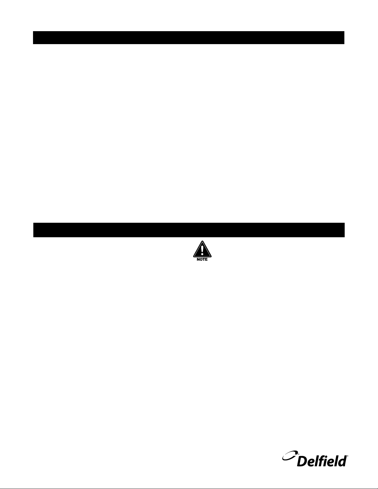
Place Unit #1.
2.
Concepts Installation Manual
First view of units placed next to
each other
Level Unit #1 front to back and left to right by adjusting the bullet
3.
feet.
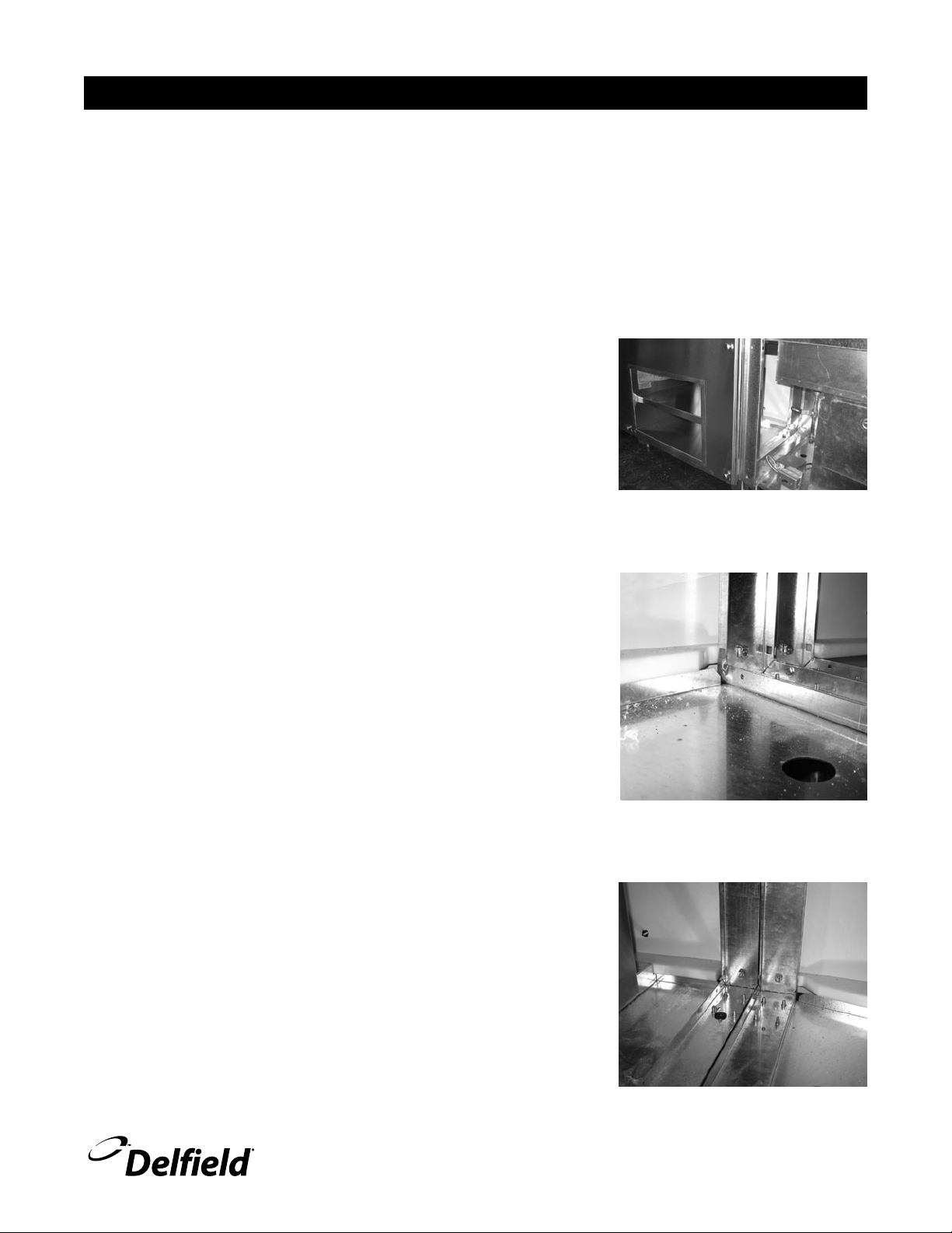
Place Unit #2.
4.
There are (approximately 3) holes along the top and bottom sides.
5.
Secure units together with 1/4” x 2” bolts and nuts. Do not tighten
until Unit #2 is level.
Level Unit #2 front to back and left to right by adjusting the bullet
6.
feet.
Tighten the nuts and bolts that connect Unit #1 and #2.
7.
Repeat steps 4-7 as you add each additional unit.
8.
Second view of units placed next to
each other
Third view of units placed next to
each other
For customer service, call (800) 733-8829, (800) 773-8821, Fax (989) 773-3210, www.delfield.com
3
Page 4

Concepts Installation Manual
CAUTION
Line Up Installation, continued
Do as much plumbing as possible with the tops off.
9.
Connect the electrical quick connects in the bases.
10.
Have the top installed. Verify it is secure and level.
11.
Install cold pans into unit. Ensure the gasket is visible.
12.
Install hot wells into unit. Ensure the gasket is visible.
13.
Make electrical connections on cold pans and hot wells.
14.
Make plumbing and drain connections on cold pans and hot wells.
15.
Moisture collecting from improper drainage can create a
slippery surface on the floor and a hazard to employees. It is the
owner’s responsibility to provide proper drainage.
Install signage, lighting and food shields as required. Instructions are
16.
found on the following pages.
Unit is ready for final utility hookups.
17.
Install tray slides.
18.
Before the heated units are used the first time for serving:
19.
Turn the temperature knob to “10” and heat the well for 15 minutes.
Do not be alarmed if smoke appears; this preheat should burn off any
residue or dust that has adhered to the food well element.
4
For customer service, call (800) 733-8829, (800) 773-8821, Fax (989) 773-3210, www.delfield.com
Page 5

Fixed Height Signage Installation
1.
Verify that black square collars are mounted in the 2”
square holes in the unit top. If they are not, locate them
in the crate and place them back in the holes in top.
2.
Make sure the push pins are removed from the mounting
brackets in the bottom of the base.
Concepts Installation Manual
3.
With a person supporting each post of the signage, pick
up and hold vertically over top of the collared holes in
top.
4.
If electrical cord is coming out the bottom of one of the
posts, lower it through the collared hole.
5.
Next, lower signage posts down through collared holes
in top.
6.
Secure in place by sliding push pin through bracket and
post.
7.
If electrical cord is present, plug into the outlet in the
base.
Prepare base.
Signage post installed in base.
For customer service, call (800) 733-8829, (800) 773-8821, Fax (989) 773-3210, www.delfield.com
5
Page 6

Concepts Installation Manual
Signage Lighting Installation
To mount decorative lamps:
Pull down on the tab on the side of the lamp’s connection
1.
box, push the connection post up into the track, then
rotate it 90 degrees until the connector locks into place.
Make sure to twist the connection box so that the side of
2.
the connection post with (2) metallic tabs aligns with the
side of the track with the (2) copper strips
If the light is mounted with the (2) metallic tabs toward
3.
the side of the track with only (1) copper strip, the light
will not work. To correct this, simply pull down on the
tab on the side of the lamp’s connection box and twist it
90 degrees until it releases from the track. Then, rotate
it 180 degrees and mount back into the track using the
directions above.
To mount flexible spotlights:
Locate the metallic tabs and strips.
Pull down on the collar that encompasses the connection
1.
box, push the connection post up into the track and then
rotate it 90 degrees until it locks into place.
Make sure to twist the connection box so that the side of
2.
the connection post with (2) metallic tabs aligns with the
side of the track with the (2) copper strips.
If the light is mounted with the (2) metallic tabs toward
3.
the side of the track with only (1) copper strip, the light
will not work. To correct this, simply pull down on the tab
on the side of the lamp’s connection box and twist it until
it is released from the track. Then, rotate it 180 degrees
and mount back into the track using the directions above.
Decorative lamp installation steps.
Flexible spotlight installation steps.
6
For customer service, call (800) 733-8829, (800) 773-8821, Fax (989) 773-3210, www.delfield.com
Page 7

FlexiShield® Food Shields Installation
Set food shield on base unit. See Figure 1.
1.
Mark hole locations.
2.
For counter top mounting mark the flange holes. See Figure 2.
•
For under counter mounting mark the leg locations.
•
Drill holes in base unit.
3.
For counter top mounting drill 5/32” holes.
•
For under counter mounting drill 3/8” holes.
•
Install with screws provided.
4.
For counter top mounting install with screws through the flanges.
•
Concepts Installation Manual
Figure 1. By placing the food
shield on the base unit, hole
locations can be marked.
For under counter mounting install with 1/4”-20 bolts and washers
•
from beneath the counter. See Figure 3.
Make any necessary electrical connections.
5.
If applicable test lights, heat lamps etc.
6.
Adjust glass for proper alignment.
7.
Clean food shield and glass with a glass cleaning agent.
8.
Figure 2. Flange dimensions
Figure 3. Bolt and washer beneath
counter.
For customer service, call (800) 733-8829, (800) 773-8821, Fax (989) 773-3210, www.delfield.com
7
Page 8

Concepts Installation Manual
!37)4#(
/04)/.!,
(!n
(!n
(!n
(!n
(!n
(!n
(!(%!4%2!33%-",9
, ' ,
!n0/,%37)4#(
/04)/.!,
(!n
(!n
(!n
(!n
(!n
(!n
(!(%!4%2!33%-",9
!,,7)2).'
-).)-5-!7'
#
,
,
'
,
1000 W - 120V
OR 1000/1222 W -
208-230 V
HEATING ELEMENT
PILOT LIGHT
(FURNISHED)
INFINITE CONTROL
WITH “OFF”
POSITION
TO ADDITIONAL
FOOD WARMERS
LINE
WIRES
P
L1
L2
H1
H2
AMPERES
IN LINE
WIRES
208-230V, 3 PHASE
#
OF
WARMERS
120V,
1
PHASE
208V,
1 PHASE
230V,
1
PHASE
L1 L2 L3
1 8.3 4.8 5.3
2 16.7 9.6 10.6
3 25 14.4 15.9 14.4/15.9
4 33.3 19.2 21.3
5 24 26.6
6 28.8 31.3
19.2/21.3
24/26.1
28.8/31.3
14.4/15.9
14.4/15.9
19.2/21.3
19.2/21.3
14.4/15.9
19.2/21.3
28.8/31.3
28.8/31.3
Wiring Diagram, Heated Serving Counter
8
Standard Single Phase Optional Three Phase
For customer service, call (800) 733-8829, (800) 773-8821, Fax (989) 773-3210, www.delfield.com
Page 9

Concepts Installation Manual
COOLING T'STAT
CONDENSER FAN
COMPRESSOR
115V
L1
N
G
S
C
R
ON/OFF SWITCH
CONDENSER FAN
COMPRESSOR
115V
S
C
R
L1
N
G
COOLING T'STAT
CONDENSER FAN
COMPRESSOR
120V
L1
N
S
C
R
G
ON/OFF SWITCH
Wiring Diagram, Self-Contained Mechanically Cooled Serving Counter
Wiring Diagram, Self-Contained LiquiTec® Cold Pan Serving Counter
Wiring Diagram Self-Contained Frost Top Serving Counter
9
For customer service, call (800) 733-8829, (800) 773-8821, Fax (989) 773-3210, www.delfield.com
Page 10

Concepts Installation Manual
Standard One Year Warranty (One year parts and labor)
The Delfield Company (“Delfield”) warrants to the Original
Purchaser of the Delfield product (herein called the “Unit”)
that such Unit, and all parts thereof, will be free from defects
in material and workmanship under normal use and service
for a period of one (1) year from the date of shipment of the
Unit to the Original Purchaser or, if the Original Purchaser
returns the warranty card completely filled out including the
date of installation within thirty (30) days of receipt of the
Unit, one (1) year from the date of installation. During this
one year warranty period, Delfield will repair or replace any
defective part or portion there of returned to Delfield by the
Original Purchaser which Delfield determines was defective
due to faulty material or workmanship. During this one year
warranty period, Delfield will pay labor, crating, and freight
incurred in the removal of the Unit of defective component
and shipment to Delfield. A maximum of 1-hour is allowed
to diagnose a defective component. A maximum of 1-hour
is allowed for retrieval of parts not in stock. A maximum
travel distance of 100 miles round trip and 2-hours will be
reimbursed. Overtime, installation/start-up, normal control
adjustments, general maintenance, glass breakage, freight
damage, and/or correcting and end-user installation error will
not be reimbursed under warranty unless pre-approved with a
Service Work Authorization from Delfield. Delfield will pay the
return costs if the Unit or part thereof was defective.
The term “Original Purchaser” as used herein means that
person, firm, association, or corporation for whom the Unit was
originally installed.
This warranty does not apply to any Unit or part thereof that
has been subjected to misuse, neglect, alteration, or accident,
such as accidental damage to the exterior finish, operated
contrary to the recommendations specified by Delfield; or
repaired or altered by anyone other than Delfield in any way
so as to, in Delfield’s sole judgement, affect its quality or
efficiency. This warranty does not apply to any Unit that has
been moved from the location where it was originally installed.
This warranty also does not cover the refrigerator drier or the
light bulbs used in the Unit. The warranty is subject to the
user’s normal maintenance and care responsibility as set forth
in the Service and Installation Manual, such as cleaning the
condenser coil, and is in lieu of all other obligations of Delfield.
Delfield neither assumes, nor authorizes any other person
to assume for Delfield, any other liability in connection with
Delfield’s products.
Removal or defacement of the original Serial Number or Model
Number from any Unit shall be deemed to release Delfield from
all obligations hereunder or any other obligations, express or
implied.
If shipment of a replacement part is requested prior to the
arrival in the Delfield factory of the part claimed to be defective,
the Original Purchaser must accept delivery of the replacement
part of a C.O.D. basis, with credit being issued after the part
has been received and inspected at Delfield’s plant and
determined by Delfield to be within this warranty.
Under no condition does this warranty give the Original
Purchaser the right to replace the defective Unit with a complete
Unit of the same manufacturer or of another make. Unless
authorized by Delfield in writing, this warranty does not permit
the replacement of any part, including the motor-compressor,
to be made with the part of another make or manufacturer.
No claims can be made under this warranty for spoilage of any
products for any reason, including system failure.
The installation contractor shall be responsible for building
access, entrance and field conditions to insure sufficient
clearance to allow any hood(s), vent(s), or Unit(s) if necessary,
to be brought into the building. Delfield will not be responsible
for structural changes or damages incurred during installation
of the Unit or any exhaust system.
Delfield shall not be liable in any manner for any default or
delay in performance hereunder caused by or resulting from
any contingency beyond Delfield’s control, including, but not
limited to, war, governmental restrictions or restraints, strike,
lockouts, injunctions, fire, flood, acts of nature, short or reduced
supply of raw materials, or discontinuance of the parts by the
original part manufacturer.
Except as provided in any Additional Four Year Protection
Plan, if applicable, and the Service Labor Contract, if
applicable, the foregoing is exclusive and in lieu of all other
warranties, whether written or oral, express or implied. This
warranty supersedes and excludes any prior oral or written
representations or warranties. Delfield expressly disclaims any
implied warranties of merchantability, fitness for a particular
purpose of compliance with any law, treaty, rule or regulation
relating to the discharge of substances into the environment.
The sole and exclusive remedies of any person relating to
the Unit, and the full liability of Delfield for any breach of this
warranty, will be as provided in this warranty.
Other than this Delfield Standard One Year Limited Warranty,
any applicable Delfield Additional Four Year Protection Plan
or applicable Delfield Service Labor Contract, the Original
Purchaser agrees and acknowledges that no other warranties
are offered or provided in connection with or for the unit or any
other part thereof.
Parts furnished by suppliers to Delfield are guaranteed by
Delfield only to the extent of the original manufacturer’s
express warranty to Delfield. Failure of the Original Purchaser
to receive such manufacturer’s express warranty to Delfield.
Failure of the Original Purchaser to receive such manufacturers
warranty shall in no way create any warranty, expressed or
implied, or any other obligation or liability on Delfield’s part in
respect thereof.
10
For customer service, call (800) 733-8829, (800) 773-8821, Fax (989) 773-3210, www.delfield.com
In no event will Delfield be liable for special, incidental or
consequential damages, or for damages in the nature of
penalties.
Page 11

Additional Four Year Protection Plan (for Motor-Compressor only)
Installation
Delfield Model# Serial # Date
Concepts Installation Manual
In addition to the Standard One Year Warranty on the MotorCompressor contained in the above listed Delfield product (the
“Unit”), The Delfield Company (“Delfield”) also agrees to repair, or
exchange with similar or interchangeable parts in design and capacity
at Delfield’s option, the defective Motor-Compressor contained in the
Unit (the “Motor-Compressor), or any part thereof, for the Original
Purchaser only, at any time during the four (4) years following the
initial one (1) year period commencing on the date of installation for
the Original Purchaser. Failure of the Original Purchaser to register
the registration card containing the Original Purchasers name,
address, date of installation, model number and serial number
of the Unit containing the Motor-Compressor within 30 days from
the date of installation shall void this warranty. This additional
warranty is only available if the Motor-Compressor is inoperative
due to defects in material or factory workmanship, as determined by
Delfield in its sole judgement and discretion. The Original Purchaser
shall be responsible for returning the defective Motor-Compressor to
Delfield prepaid, F.O.B. at the address shown on the back cover of this
manual.
The term “Original Purchaser” as used herein means that person,
firm, association, or corporation for whom the Unit was originally
installed.
The term “Motor-Compressor” as used herein does not include unit
base, air or water cooled condenser, receiver, electrical accessories
such as relay, capacitors, refrigerant controls, or condenser fan/motor
assembly. This warranty does not cover labor charges incidental to
the replacement of parts. This warranty further does not include
any equipment to which said condensing unit is connected, such as
cooling coils, temperature controls or refrigerant metering devices.
This warranty shall be void if the Motor-Compressor, in Delfield’s
sole judgement, has been subjected to misuse, neglect, alteration or
accident, operated contrary to the recommendations specified by the
Unit manufacturer, repaired or altered by anyone other than Delfield
in any way so as, in Delfield’s sole judgment, to affect its quality or
efficiency or if the serial number has been altered, defaced or removed.
This Warranty does not apply to a Motor-Compressor in any Unit that
has been moved from the location where it was originally installed.
The addition of methyl chloride to the condensing unit or refrigeration
system shall void this warranty.
General Conditions
Delfield shall not be liable in any manner for any default or delay in
performance hereunder caused by or resulting from any contingency
beyond Delfield’s control, including, but not limited to, war,
governmental restrictions or restraints, strike, lockouts, injunctions,
fire, flood, acts of nature, short or reduced supply of raw materials,
or discontinuance of any part or the Motor-Compressor by the unit
manufacturer.
Replacement of a defective Motor-Compressor is limited to one (1)
Motor-Compressor by us during the four (4) year period. Delfield
shall replace the Motor-Compressor at no charge.
This warranty does not give the Original Purchaser of the MotorCompressor the right to purchase a complete replacement MotorCompressor of the same make or of another make. It further does
not permit the replacement to be made with a Motor-Compressor
of another kind unless authorized by Delfield. In the event Delfield
authorizes the Original Purchaser to purchase a replacement MotorCompressor locally, only the wholesale cost of the Motor-Compressor
is refundable.
Expressly excluded from this warranty are damages resulting from
spoilage of goods.
Except as provided in any applicable Standard One Year Limited
Warranty or applicable Service Labor Contract, the foregoing is
exclusive and in lieu of all other warranties, whether written or
oral, express or implied. This Warranty supersedes and excludes
any prior oral or written representations or warranties. Delfield
expressly disclaims any implied warranties of merchantability,
fitness for a particular purpose or compliance with any law, treaty,
rule or regulation relating to the Motor-Compressor, and the full
liability of Delfield for any breach of this warranty, will be as
provided in this warranty.
Other than any applicable Delfield Standard One year Limited Warranty,
this Delfield Additional Four Year Protection Plan and any applicable
Delfield Service Labor Contract, the Original Purchaser agrees and
acknowledges that no other warranties are offered or provided in
connection with or for the Motor-Compressor or any part thereof.
In no event will Delfield be liable for special, incidental or consequential
For customer service, call (800) 733-8829, (800) 773-8821, Fax (989) 773-3210, www.delfield.com
11
Page 12

Mt. Pleasant, MI
Covington, TN
Thank you for choosing Delfield!
Help is a phone call away. Help our team of professional, courteous customer service
reps by having your model number and serial number available at the time
of your call (800) 733-8829
Model: ____________________ S/N: ____________________
Installation Date: __________________
For a list of Deleld’s authorized parts depots,
visit our website at www.deleld.com
980 S. Isabella Rd., Mt. Pleasant, MI 48858, U.S.A. • (989) 773-7981 or (800) 733-8829 • Fax (989) 773-3210 • www.delfield.com
Delfield reserves the right to make changes in design or specifications without prior notice. ©2010 The Delfield Company. All rights reserved. Printed in the U.S.A.
DMCNCPTInstall 04/10
 Loading...