

Page 1

Compact Refrigerators & Freezers
400 & 4000 Series
Original Instructions
Service Manual
English
Part Number 400_4000_Service_Manual 01/18
Page 2

Safety Notices
Warning
n
Read this manual thoroughly before operating, installing
or performing maintenance on the equipment. Failure
to follow instructions in this manual can cause property
damage, injury or death.
DANGER
Do not install or operate equipment that has been
misused, abused, neglected, damaged, or altered/
modified from that of original manufactured
specifications.
DANGER
Keep power cord AWAY from HEATED surfaces. DO NOT
immerse power cord or plug in water. DO NOT let power
cord hang over edge of table or counter.
DANGER
All utility connections and fixtures must be maintained
in accordance with Local and national codes.
Warning
n
Authorized Service Representatives are obligated to
follow industry standard safety procedures, including,
but not limited to, local/national regulations for
disconnection / lock out / tag out procedures for all
utilities including electric, gas, water and steam.
Warning
n
Do not store or use gasoline or other flammable vapors
or liquids in the vicinity of this or any other appliance.
Never use flammable oil soaked cloths or combustible
cleaning solutions, for cleaning.
Warning
n
Do not use electrical appliances or accessories other
than those supplied by the manufacturer.
Warning
n
Use caution when handling metal surface edges of all
equipment.
Warning
n
This appliance is not intended for use by persons
(including children) with reduced physical, sensory
or mental capabilities, or lack of experience and
knowledge, unless they have been given supervision
concerning use of the appliance by a person responsible
for their safety. Do not allow children to play with this
appliance.
Caution
,
Use caution handling, moving and use of the R290
refrigerators to avoid either damaging the refrigerant
tubing or increasing the risk of a leak. Components
shall be replaced with like components. Servicing shall
be done by a factory authorized service personnel to
minimize the risk of possible ignition due to incorrect
parts or improper service.
Notice
Proper installation, care and maintenance are
essential for maximum performance and trouble-free
operation of your equipment. Visit our website www.
mtwkitchencare.com for manual updates, translations,
or contact information for service agents in your area.
Warning
n
This product contains chemicals known to the State
of California to cause cancer and/or birth defects or
other reproductive harm. Operation, installation, and
servicing of this product could expose you to airborne
particles of glasswool or ceramic fibers, crystalline
silica, and/or carbon monoxide. Inhalation of airborne
particles of glasswool or ceramic fibers is known to the
State of California to cause cancer. Inhalation of carbon
monoxide is known to the State of California to cause
birth defects or other reproductive harm.
Page 3

Section 1
General Information
Section 2
Installation
Section 3
Operation
Table of Contents
Model Numbers .................................................................................................................. 5
Serial Number Location ..................................................................................................... 5
Warranty Information ........................................................................................................ 5
Regulatory Certifications ..................................................................................................5
Location ..............................................................................................................................7
Weight of Equipment .........................................................................................................8
Clearance Requirements ....................................................................................................8
Dimensions ......................................................................................................................... 8
Electrical Service ................................................................................................................ 9
Voltage .......................................................................................................................................................9
Rated Amperages, Horsepower, Voltage & Power Cord Chart ...............................................9
Heat of Rejection ................................................................................................................ 9
Drain Connections ............................................................................................................10
Caster Or Leg Installation ................................................................................................10
Leg Leveling .......................................................................................................................................... 10
Caster and Leg Mounting Detail .................................................................................................... 11
Loosen Freezer Compressor Bolts ................................................................................... 11
Section 4
Maintenance
Section 5
Troubleshooting
Controls/Programming/Settings ....................................................................................14
R404A Refrigerators ............................................................................................................................ 14
R290 Refrigerators ............................................................................................................................... 14
Freezers ................................................................................................................................................... 15
Evaporator Fan Operation ................................................................................................................ 15
Cleaning and Sanitizing Procedures ...............................................................................17
General .................................................................................................................................................... 17
Interior Cleaning .................................................................................................................................. 18
Exterior Cleaning ................................................................................................................................. 18
Doors/Hinges ........................................................................................................................................ 18
Preventing Blower Coil Corrosion ................................................................................................. 19
Field Installation ..................................................................................................................................19
Casters ..................................................................................................................................................... 19
Cleaning the Condenser Coil .......................................................................................................... 19
Drain ......................................................................................................................................................... 19
Evaporator Drain Line Maintenance, Part 1 ..................................................................20
Evaporator Drain Line Maintenance, Part 2 ...................................................................20
Problem -> Cause -> Correction Chart ............................................................................21
Part Number 400_4000_Service_Manual 01/18 3
Page 4

Section 6
Refrigeration
R404A
R290
Section 7
Air Flow
Table of Contents (continued)
Refrigerant Recovery / Evacuation & Recharging .......................................................... 23
Charging Procedures .......................................................................................................23
System Contamination Clean-up ....................................................................................24
Mild System Contamination Clean-Up Procedure .........................................................25
Severe System Contamination Clean-Up Procedure .....................................................25
Filter Driers .......................................................................................................................26
Refrigerant Re-Use Policy ................................................................................................26
Refrigeration Components Overview .............................................................................27
Properties of R-290 (Propane) .........................................................................................28
Service Procedures ...........................................................................................................29
Normal Operating Temperatures for Models Using Refrigerant R290 .........................31
86°F (30°C) Ambient / 32° (0°C) Degree Box Temperature ...........................................32
100°F (38°C) Ambient / 32°F (0°C) Box Temperature .....................................................33
Review ...............................................................................................................................34
Unit Air Flow Design ........................................................................................................35
Section 8
Control
Power Cord at Junction Box .............................................................................................36
R290 Refrigeration Control Specifications .....................................................................36
Control Thermistor Connections .....................................................................................37
Thermistor Installation ....................................................................................................37
Unit Operation ..................................................................................................................37
Service Tips ......................................................................................................................37
Section 9
Diagrams
R404A Compressor Wiring ...............................................................................................38
Models 402, 406, 406CA, ST4048 & UC4048 ..................................................................39
402P, 406P, 406CAP, ST4048P, UC4048P ......................................................................... 40
Export Models 402-CE, 406-CE, 406CA-CE, ST4048-CE & UC4048-CE ..........................41
Models 403, 407, 407CA, ST4148 & UC4148 ..................................................................42
Export Models 403-CE, 407-CE & 407CA-CE ................................................................... 43
Export Models ST4148-CE & UC4148-CE ........................................................................ 44
Section 10
Replacement Procedures
406P - Connect Compressor’s Starter Box ...................................................................... 45
Door Mounting Bracket ...................................................................................................46
Door Gasket ...................................................................................................................... 46
4 Part Number 400_4000_Service_Manual 01/18
Page 5

Section 1
General Information
Model Numbers
This manual covers standard units only.
NOTE: For custom units, consult Manitowoc KitchenCare at
1-844-724-CARE.
Work Top Refrigerator Bases With Stainless Steel Top &
Backsplash
402, 402P ST4048, ST4048P
Undercounter Refrigerator Bases With Stainless Steel Top
406, 406P UC4048, UC4048P
Undercounter Refrigerator With Subtop And 3.75” Casters
406CA, 406CAP
The prefix P on a model number indicates the use of the
refrigerant propane.
Work Top Freezer Bases With Stainless Steel Top &
Backsplash
403 ST4148
Undercounter Freezer Bases With Stainless Steel Top
407 UC4148
Undercounter Freezer With Subtop And 3.75” Casters
407CA
Serial Number Location
The serial number on 400 series compact refrigerators and
freezers is printed on the right side of the interior back wall.
The serial tag on 4000 series compact refrigerators and
freezers is located either on the left upper sidewall inside
the cabinet or under the top nosing directly above the door
when the door is in the closed position (right hand door
when there are two doors).
Always have the serial number of your unit available
when calling for parts or service.
Warranty Information
Visit
http://www.delfield.com/minisite/service/warranty_info to:
• Register your product for warranty.
• Verify warranty information.
• View and download a copy of your warranty.
Regulatory Certifications
Models are certified by:
• National Sanitation Foundation (NSF)
• Underwriters Laboratories (UL)
• Underwriters Laboratories of Canada (CUL)
Part Number 400_4000_Service_Manual 01/18 5
Page 6

General Information Section 1
THIS PAGE INTENTIONALLY LEFT BLANK
6 Part Number 400_4000_Service_Manual 01/18
Page 7

Section 2
Installation
DANGER
Installation must comply with all applicable fire and
health codes in your jurisdiction.
DANGER
Use appropriate safety equipment during installation
and servicing
Warning
n
Remove all removable panels before lifting and
installing.
Warning
n
Do not damage the refrigeration circuit when installing,
maintaining or servicing the unit.
Location
Warning
n
This equipment must be positioned so that the plug is
accessible unless other means for disconnection from
the power supply (e.g., circuit breaker or disconnect
switch) is provided.
Warning
n
Adequate means must be provided to limit the
movement of this appliance without depending on or
transmitting stress to the electrical conduit or gas lines.
Warning
n
To avoid instability the installation area must be capable
of supporting the combined weight of the equipment
and product. Additionally the equipment must be level
side to side and front to back.
Warning
n
This equipment is intended for indoor use only. Do not
install or operate this equipment in outdoor areas.
Caution
,
Do not position the air intake vent near steam or heat
exhaust of another appliance.
The location selected for the equipment must meet the
following criteria. If any of these criteria are not met, select
another location.
• Units are intended for indoor use only.
• The location MUST be level, stable and capable of
supporting the weight of the equipment.
• The location MUST be free from and clear of
combustible materials.
• Equipment MUST be level both front to back and side to
side.
• Position the equipment so it will not tip or slide.
• Front casters MUST be locked once positioned.
• Recommended air temperature is 41° - 86°F (5° - 30°C).
• Proper air supply for ventilation is REQUIRED AND
CRITICAL for safe and efficient operation. Refer to
Clearance Requirements chart on page 8.
• Do not obstruct the flow of ventilation air. Make sure the
air vents of the equipment are not blocked.
Part Number 400_4000_Service_Manual 01/18 7
Page 8

Installation Section 2
• Do not install the equipment directly over a drain.
Steam rising up out of the drain will adversely affect
operation, air circulation, and damage electrical /
electronic components.
Weight of Equipment
Model Weight
402, 402P 176lbs (80kg)
403 184lbs (83kg)
406, 406P 176lbs (80kg)
406CA, 406CAP 168lbs (76kg)
407 176lbs (80kg)
407CA 168lbs (76kg)
ST4048, ST4048P 234lbs (106kg)
ST4148 242lbs (110kg)
UC4048, UC4048P 236lbs (107kg)
UC4148 236lbs (107kg)
Clearance Requirements
DANGER
Minimum clearance requirements are the same for
noncombustible locations as for combustible locations.
The flooring under the appliance must be made of a
noncombustible material.
DANGER
Risk of fire/shock. All minimum clearances must be
maintained. Do not obstruct vents or openings.
Back 3.00” (76mm)
Top / Sides 1.00” (25mm)
Bottom 2.00” (51mm)
• Keep the vents clean and free of obstruction.
• The factory installed legs must be used and not
removed.
Dimensions
Model Length Depth Height
402,
402P
403 27” (69cm) 28.5” (72cm) 39.5” (100cm)
406,
406P
406CA,
406CAP
407 27” (69cm) 28.5” (72cm) 35.5” (90cm)
407CA 27” (69cm) 27.75” (70cm) 33.25” (84cm)
ST4048,
ST4048P
ST4148 48” (122cm) 28.5” (72cm) 39.5” (100cm)
UC4048,
UC4048P
UC4148 48” (122cm) 28.5” (72cm) 35.5” (90cm)
Model Volume Shelf Space
402
402P
403
406
406P
406CA
406CAP
407
407CA
ST4048
ST4048P
ST4148
UC4048
UC4048P
UC4148
27” (69cm) 28.5” (72cm) 39.5” (100cm)
27” (69cm) 28.5” (72cm) 35.5” (90cm)
27” (69cm) 27.75” (70cm) 33.25” (84cm)
48” (122cm) 28.5” (72cm) 39.5” (100cm)
48” (122cm) 28.5” (72cm) 35.5” (90cm)
3
5.7Ft
(161L) 4.6Ft2 (43dm2)
3
10.80Ft
(306L) 8.0Ft2 (74dm2)
8 Part Number 400_4000_Service_Manual 01/18
Page 9
Section 2 Installation
Electrical Service
DANGER
Check all wiring connections, including factory
terminals, before operation. Connections can become
loose during shipment and installation.
DANGER
Units with two power cords must be plugged into
individual branch circuits. During movement, cleaning
or repair it is necessary to unplug both power cords.
Warning
n
This appliance must be grounded and all field wiring
must conform to all applicable local and national
codes. Refer to rating plate for proper voltage. It is the
responsibility of the end user to provide the disconnect
means to satisfy the authority having jurisdiction.
VOLTAGE
All electrical work, including wire routing and grounding,
must conform to local, state and national electrical codes.
The following precautions must be observed:
• The equipment must be grounded.
• A separate fuse/circuit breaker must be provided for
each unit.
• A qualified electrician must determine proper wire size
dependent upon location, materials used and length
of run (minimum circuit ampacity can be used to help
select the wire size).
• The maximum allowable voltage variation is ±10% of
the rated voltage at equipment start-up (when the
electrical load is highest).
• Check all green ground screws, cables and wire
connections to verify they are tight before start-up.
RATED AMPERAGES, HORSEPOWER, VOLTAGE &
POWER CORD CHART
Units with plugs are supplied with approximately 6ft
(183cm) cords.
Models 406 and 407 may be stacked using a stacking collar.
In this case two 6ft (183cm) long grounded supply cords
and plugs are standard.
Model Amps HP Voltage,
Cycle, Phase
402,
402P
403 5.8
406,
406CA,
406CAP
406P
407,
407CA
ST4048,
ST4048P
ST4148 5.6 1/3
UC4048,
UC4048P
UC4148 5.6 1/3
4.0
4.0
5.8
4.0
4.0 1/5
1/5
115/60/1 5-15P
NEMA
Plug
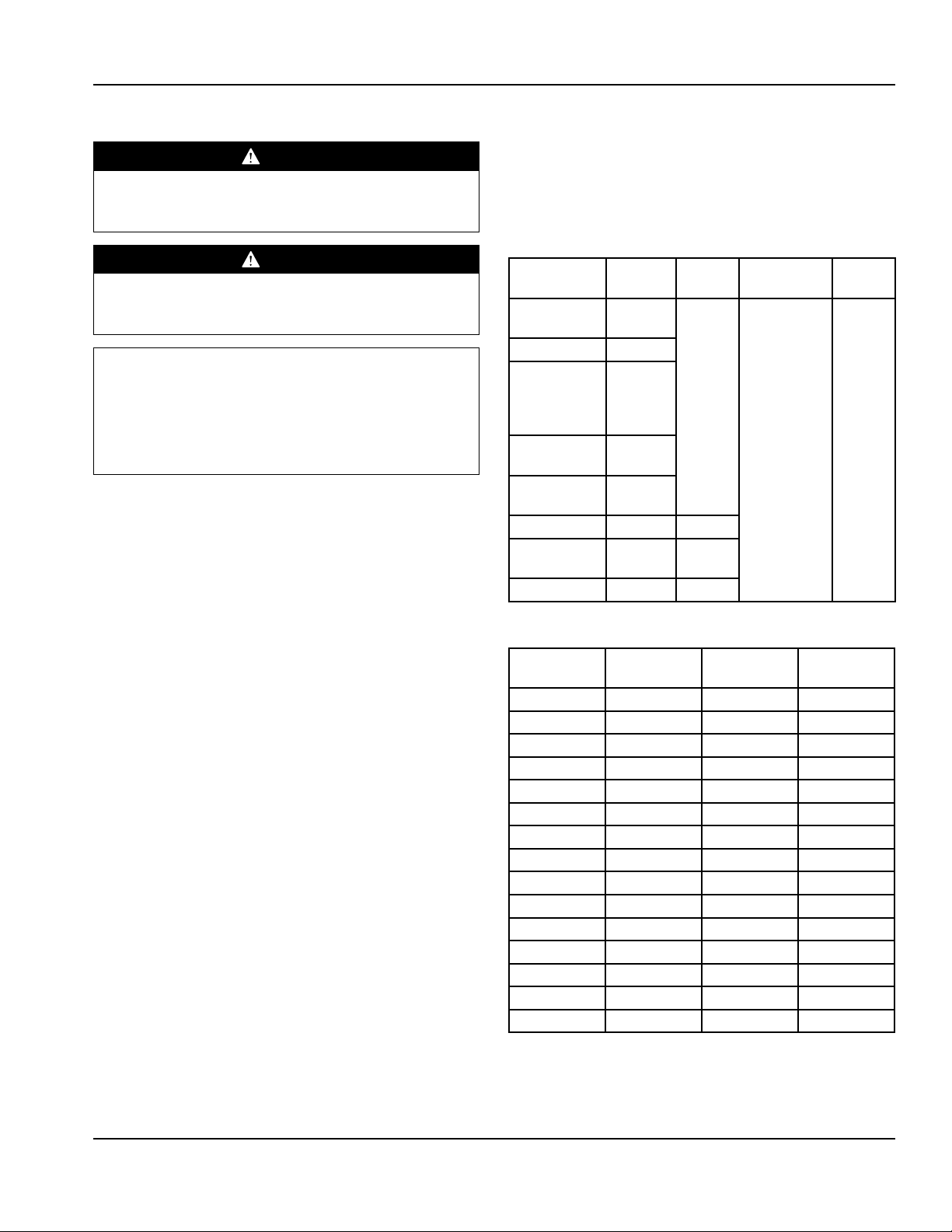
Heat of Rejection
Model BTU/Hour
Capacity
402 1100 1430 7oz R404A
402P 1356 210 100g R290
403 840 1092 7oz R404A
406 1100 1430 7oz R404A
406CA 1100 1430 7oz R404A
406CAP 1356 210 100g R290
406P 1356 210 100g R290
407 800 339 6.5oz R404A
407CA 800 339 6.5oz R404A
ST4048 1100 1430 7oz R404A
ST4048P 1356 316 100g R290
ST4148 1080 1404 7oz R404A
UC4048 1100 1430 7oz R404A
UC4048P 1356 316 100g R290
UC4148 1080 1404 7oz R404A
Heat of
Rejection
Charge
Part Number 400_4000_Service_Manual 01/18 9
Page 10

Installation Section 2
Drain Connections
Warning
n
If a refrigerated base does not have a condensate
evaporator supplied, you must connect the condensate
line to a suitable drain. Otherwise, water will collect on
the floor, causing a potentially hazardous situation.
Warning
n
Moisture collecting from improper drainage can create a
slippery surface on the floor and a hazard to employees.
It is the owner’s responsibility to provide a container or
outlet for drainage.
Caster Or Leg Installation
DANGER
Legs or casters must be installed and the legs or casters
must be screwed in completely to prevent bending.
When casters are installed the mass of this unit will
allow it to move uncontrolled on an inclined surface.
These units must be tethered/secured to comply with
all applicable codes.
Installation Instructions
1. Carefully place the unit on its back.
2. Located at each caster mounting location are 4 Phillips
head screws, for a total of 16 screws. Remove them.
3. Place a locking plate caster or leg over one of the front
holes, matching the 4 mounting holes to the pre-drilled
holes in the underside of the unit. Insert 4 Phillips head
screws and tighten. Repeat with the other locking front
caster or leg.
4. Repeat step 3 with the non-locking casters or legs in
the rear of the unit.
5. Carefully lift the unit upright.
Caution
,
After installing casters, the unit must stand upright for
twenty-four (24) hours before being powered up to
assure oil return to the compressor sump.
Plate Casters
With Locks
Warning
n
The unit must be installed in a stable condition with
the front wheels locked. Locking the front casters after
installation is the owner’s and operator’s responsibility.
Warning
n
Use a jack to lift the refrigeration unit off the ground
just far enough to remove the leg/caster. Place blocking
underneath the unit. Do not work underneath a raised
unit without proper blocking. Do not lift the unit more
than necessary to remove the leg/caster. Lifting the unit
too far can make the unit unstable.
Caution
,
All single-section units require that the sw ivel casters
be mounted on the front and rigid casters be mounted
on the rear.
Plate Casters
Without Locks
Screws
LEG LEVELING
All four legs are adjustable. Adjust each leg until the unit is
stable and level left to right. If necessary adjusting the front
legs slightly higher than the rear by about 1/8” (3mm) will
help the door remain closed.
10 Part Number 400_4000_Service_Manual 01/18
Page 11

Section 2 Installation
2.38”
(60mm)
3.40”
(86mm)
2.38”
(60mm)
3.40”
(86mm)
2.82”
(72mm)
1.75”
(44mm)
CASTER AND LEG MOUNTING DETAIL
A universal bolt hole pattern is provided on the bottom of
the cabinet. It will accommodate any leg or caster. Simply
line up the plate holes with the corresponding cabinet
holes.
2.38”
(60mm)
3.40”
(86mm)
NOTE: If hole pattern on caster/leg matches the one above
mount in outer set of holes.
• 6” Leg - 3234569
1.75”
(44mm)
0.94”
(24mm)
2.14”
(54mm)
NOTE: If hole pattern on caster/leg matches the one above
mount in inner set of holes.
• 2” Caster - 3234148
Loosen Freezer Compressor Bolts
Semi hermetic models should be loosened before
operating. Loosen (but do not remove) the bolts on the
compressor. If not done the freezer may vibrate excessively
when the compressor is running,
2.82”
(72mm)
NOTE: If hole pattern on caster/leg matches the one above
mount in middle set of holes.
• 3” Caster - 3234024
• 5” Caster - 3234161
• 6” Leg - 3234791
Part Number 400_4000_Service_Manual 01/18 11
Page 12

Installation Section 2
THIS PAGE INTENTIONALLY LEFT BLANK
12 Part Number 400_4000_Service_Manual 01/18
Page 13

Section 3
Operation
DANGER
The on-site supervisor is responsible for ensuring that
operators are made aware of the inherent dangers of
operating this equipment.
DANGER
Do not operate any appliance with a damaged cord
or plug. All repairs must be performed by a qualified
service company.
DANGER
Never stand on the unit! They are not designed to
hold the weight of an adult, and may collapse or tip if
misused in this manner.
Warning
n
Do not contact moving parts.
Caution
,
Do not throw items into the storage area. Failure to
heed this recommendation could result in damage to
the interior of the cabinet or to the blower coil.
Warning
n
All covers and access panels must be in place and
properly secured, before operating this equipment.
Warning
n
Do not use electrical appliances inside the food storage
compartment of this appliance.
Warning
n
The operator of this equipment is solely responsible
for ensuring safe holding temperature levels for all
food items. Failure to do so could result in unsafe food
products for customers.
Warning
n
Overloading shelves can damage equipment or cause
bodily injury.
Warning
n
Damp or wet hands may stick to cold surfaces.
Caution
,
Do not block the supply and return air grills or the air
space around the air grills. Keep plastic wrappings,
paper, labels, etc. from being airborne and lodging in
the grills. Failure to keep the air grills clear will result in
unsatisfactory operation of the system.
Part Number 400_4000_Service_Manual 01/18 13
Page 14

Operation Section 3
Controls/Programming/Settings
R404A REFRIGERATORS
After the unit is connected to power it will automatically
begin operating. With the doors closed, the temperature
of the cabinet should reach 36°F to 40°F (2°C to 4°C) on
refrigerators in about one hour.
A thermostat located in the evaporator housing on interior
rear of the unit, controls the temperature in the box. The
factory setting for the control is 4 and maintains about 38°F
(3°C) in the box. Set toward 1 for higher temperatures and
toward 7 for lower temperatures.
Refrigerators defrost automatically with every cycle of the
compressor. The water generated is routed to a pan on the
rear of the unit and is evaporated by the heat given off by
the compressor.
During normal operation the evaporator fan may cycle
and/or pulse independently of the compressor. Consult
the service manual or contact Technical Support at
1-844-724-CARE if you are unsure of the proper
function.
R290 REFRIGERATORS
At initial start-up or anytime power is disconnected, then
reconnected to the unit, the control will delay all operations
for a short time (up to 30 minutes.) While in this delay
period the control will initialize.
With the doors closed, the temperature of the cabinet
should reach 36°F to 40°F (2°C to 4°C) on refrigerators
in about one hour. The electronic temperature control
constantly monitors box temperature and evaporator coil
temperature to maintain consistent product temperatures.
Refrigerators periodically go into defrost to allow
the accumulated frost on the evaporator to clear, the
compressor and condenser fan motor will turn off when
the temperature control detects a certain evaporator
temperature. After the defrost cycle is complete, the
temperature control will return to a normal cooling cycle.
The water generated is routed to a pan on the rear of
the unit and is evaporated by the heat given off by the
compressor.
During normal operation the evaporator fan may cycle
and/or pulse independently of the compressor. Consult
the service manual or contact Technical Support at
1-844-724-CARE if you are unsure of the proper
function.
Electronic Temperature Control Location & Adjustment
Rear View Of R290 Refrigerator
The control is located in the control box at the rear of
the unit. Never turn the knob more than one dial
number and always allow eight hours for temperature
stabilization before making any additional adjustments.
To adjust for colder temperatures, turn the knob clockwise.
For warmer temperatures, turn the knob counterclockwise. Turn the knob fully counter-clockwise to turn the
refrigeration system off.
14 Part Number 400_4000_Service_Manual 01/18
Page 15

Section 3 Operation
FREEZERS
This unit does not have a power switch, plug the unit in
to begin operation. At initial start-up or anytime power is
disconnected, then reconnected to the unit, the control
will delay all operations for a short time (up to 40 minutes.)
While in this delay period, the control initializes the control
parameters and confirms that the temperature sensors and
circuits are operational.
After initializing, the control will immediately enter a
DEFROST mode. The compressor and condenser fan as
well as the evaporator fan will remain off until initial defrost
is complete. This initial defrost cycle may take up to 15
minutes to complete, at which time the freezing cycle will
begin.
After initializing and the defrost cycle, the electronic
temperature control will cycle the compressor, evaporator
fan motor, and condenser fan motor to maintain box
temperature at the control setting.
With the doors closed, the temperature of the cabinet
should reach 0°F (-18°C) on freezers in about one hour
after the freezing cycle begins. The electronic temperature
control constantly monitors box temperature as well as
evaporator coil temperature to maintain consistent product
temperatures. As an added energy-saving feature, the
electronic controller will switch the evaporator fan motor
on and off with the compressor and condenser fan motor.
During normal operation the evaporator fan may cycle
and/or pulse independently of the compressor. Consult
the service manual or contact Technical Support at
1-844-724-CARE if you are unsure of the proper
function.
Freezer Automatic Defrost
The control also monitors compressor total running time
and will enter a defrost cycle after total compressor running
time is greater than five hours since the last defrost cycle
OR if evaporator coil temperature drops below -34°F (-37°C)
(indicating excessive frost on the coil).
Freezer Manual Defrost
If a manual defrost is desired, simply unplug the unit for
several seconds, then plug unit back in. This will cause the
control to re-initialize and then enter a defrost cycle.
When the control enters the defrost mode, whether manual
or automatic, it switches off the evaporator fan motor,
compressor and condenser fan motor, and switches on the
defrost heater to warm the evaporator coil and melt all frost
accumulated during the previous refrigeration cycle. The
control will continue the defrost cycle for a MINIMUM of
eight minutes and a MAXIMUM of 30 minutes depending
on the amount of frost accumulated on the evaporator coil.
After the defrost cycle is complete, the control returns
to a normal refrigeration cycle, however the evaporator
fan motor will not switch on for two minutes AFTER
the compressor and condenser fan motor have begun
operating.
EVAPORATOR FAN OPERATION
Cooling Cycle Defrost Cycle
Compressor OnCompressor
Off
Evap Fan Evap Fan Evap Fan
Compressor
Off
Electronic Temperature Control Location & Adjustment
Never turn the knob more than one dial number and
always allow eight hours for temperature stabilization
before making any additional adjustments. The control
is located in the control box at the rear of the unit. It is
R404A
Refrigerators
R290
Refrigerators
Freezer On Off Off
On On On
On Cycles
On 3-Min
Off 3Min
On
factory set at mid-range to maintain about -3°F (-18°C) box
temperature. To adjust for colder temperatures, turn the
knob clockwise. For warmer temperatures, turn the knob
counter-clockwise. Turn the knob fully counter-clockwise to
turn the refrigeration system off.
Part Number 400_4000_Service_Manual 01/18 15
Page 16

Operation Section 3
THIS PAGE INTENTIONALLY LEFT BLANK
16 Part Number 400_4000_Service_Manual 01/18
Page 17

Section 4
Maintenance
DANGER
It is the responsibility of the equipment owner to
perform a Personal Protective Equipment Hazard
Assessment to ensure adequate protection during
maintenance procedures.
DANGER
Failure to disconnect the power at the main power
supply disconnect could result in serious injury or death.
The power switch DOES NOT disconnect all incoming
power.
DANGER
Disconnect electric power at the main power disconnect
for all equipment being serviced. Observe correct
polarity of incoming line voltage. Incorrect polarity can
lead to erratic operation.
Warning)
n
Never use sharp objects or tools to remove ice or frost.
Do not use mechanical devices or other means to
accelerate the defrosting process.
Cleaning and Sanitizing Procedures
Caution
,
Maintenance and servicing work other than cleaning as
described in this manual must be done by an authorized
service personnel.
GENERAL
Warning
n
When using cleaning fluids or chemicals, rubber gloves
and eye protection (and/or face shield) must be worn.
You are responsible for maintaining the equipment
in accordance with the instructions in this manual.
Maintenance procedures are not covered by the warranty.
Maintenance Daily Weekly Monthly
Interior X X X
Gasket X X X X
Exterior X X X
Drain X X X
Condenser Coil X X X
Casters X X X
After Prolonged
Shutdown
At Start-Up
Part Number 400_4000_Service_Manual 01/18 17
Page 18

Maintenance Section 4
INTERIOR CLEANING
Notice
When cleaning interior and exterior of unit, care should
be taken to avoid the front power switch and the rear
power cord. Keep water and/or cleaning solutions away
from these parts.
Notice
Never use a high-pressure water jet for cleaning or hose
down or flood interior or exterior of units with water. Do
not use power cleaning equipment, steel wool, scrapers
or wire brushes on stainless steel or painted surfaces.
The interior can be cleaned using soap and warm water. If
this isn’t sufficient, try ammonia and water or a nonabrasive
liquid cleaner.
EXTERIOR CLEANING
Notice
Never use an acid based cleaning solution on exterior
panels! Many food products have an acidic content,
which can deteriorate the finish. Be sure to clean the
stainless steel surfaces of ALL food products.
DOORS/HINGES
Over time and with heavy-use doors, the hinges may
become loose. If this happens, tighten the screws that
mount the hinge brackets to the frame of the unit. Loose
or sagging doors can cause the hinges to pull out of the
frame, which may damage both the doors and the hinges.
In some cases this may require qualified service agents or
maintenance personnel to perform repairs.
Door Adjustment
If the door needs lowering at the handle, use a 5/16” (8mm)
wrench to loosen the hinge screws and install a spacer
outside of the hinge. Tighten the screws.
If the door needs to be higher at the handle, use a 5/16”
(8mm) wrench to loosen the hinge screws and install a
spacer inside of the hinge. Tighten the screws.
Clean the area around the unit as often as necessary to
maintain cleanliness and efficient operation.
Wipe gasket and surfaces with a damp cloth rinsed in water
to remove dust and dirt from the outside of the unit. Always
rub with the “grain” of the stainless steel to avoid marring
the finish. If a greasy residue persists, use a damp cloth
rinsed in a mild dish soap and water solution. Wipe dry with
a clean, soft cloth.
Never use steel wool or abrasive pads for cleaning. Never
use chlorinated, citrus based or abrasive cleaners.
Stainless steel exterior panels have a clear coating that
is stain resistant and easy to clean. Products containing
abrasives will damage the coating and scratch the panels.
Daily cleaning may be followed by an application of
stainless steel cleaner which will eliminate water spotting
and fingerprints. Early signs of stainless steel breakdown
are small pits and cracks. If this has begun, clean thoroughly
and start to apply stainless steel cleaners in attempt to
restore the steel.
18 Part Number 400_4000_Service_Manual 01/18
Page 19

Section 4 Maintenance
PREVENTING BLOWER COIL CORROSION
To help prevent corrosion of the blower coil, store all acidic
items, such as pickles and tomatoes, in seal-able containers.
Immediately wipe up all spills.
FIELD INSTALLATION
Over shelves and other items mounted to the top of the
counters should never be installed in the field due to the
potential damage to the refrigeration system.
CASTERS
Wipe casters with a damp cloth monthly to prevent
corrosion.
CLEANING THE CONDENSER COIL
In order to maintain proper refrigeration performance, the
condenser fins must be cleaned of dust, dirt and grease
regularly. It is recommended that this be done monthly. If
conditions are such that the condenser is totally blocked
in a month, the frequency of cleaning should be increased.
Clean the condenser with a vacuum cleaner or stiff brush. If
extremely dirty, a commercially available condenser cleaner
may be required. Keep cleaning liquid away from control,
fans and compressor; keep these components dry.
Failure to maintain a clean condenser coil can initially cause
high temperatures and excessive run times. Continuous
operation with a dirty or clogged condenser coil can
result in compressor failure. Neglecting the condenser coil
cleaning procedures will void any warranties associated
with the compressor and cost to replace the compressor.
DRAIN
Each unit has a drain located inside the unit that removes
the condensation from the evaporator coil and routes it
to an external condensate evaporator pan. Each drain can
become loose or disconnected during normal use. If you
notice water accumulation on the inside of the unit, be sure
the drain tube is connected to the evaporator drain pan.
If water is collecting underneath the unit, make sure the
end of the drain tube is in the condensate evaporator. The
leveling of the unit is important as the units are designed to
drain properly when level. Be sure all drain lines are free of
obstructions.
Part Number 400_4000_Service_Manual 01/18 19
Page 20

Maintenance Section 4
Evaporator Drain Line Maintenance, Part 1
1. Unplug the power cord from the outlet or shut the
breaker off at the breaker panel if the unit is hard wired.
2. Remove the 5/16” hex head screws from the back panel
on the back side of the unit to access the drain line.
3. Disconnect the clear rubber tubing drain line from the
90º copper pipe.
Evaporator Drain Line Maintenance, Part 2
NOTE: If the unit continues to leak water after following Part
1 instructions proceed with Part 2 instructions.
1. Unplug the power cord from the outlet or shut the
breaker off at the breaker panel if the unit is hard wired.
2. Remove the shelves or drawer boxes from the unit.
3. If the unit has a center bracket that holds the shelves
up then loosen the wing nuts and remove the shelf
bracket.
4. Remove the four 5/16” hex head screws from the
evaporator cover. Pull the evaporator cover off.
4. Clean the drain line of debris using a plastic straw or
compressed air.
5. Reconnect the rubber hose drain line to the copper 90º.
6. Reinstall the back panel.
7. Plug the unit back in.
5. Locate the evaporator drain line toward the back of the
drain pan on either the left or right side.
6. Clear drain and drain line of any debris using a plastic
straw, compressed air, or warm water.
7. Reinstall the evaporator cover with the four 5/16” hex
head screws.
8. If a center bracket was removed, reinstall it and secure
it with wing nuts.
9. Reinstall the shelves or drawer boxes.
10. Plug the unit back in or turn the breaker on at the
breaker panel.
20 Part Number 400_4000_Service_Manual 01/18
Page 21

Section 5
Troubleshooting
Problem -> Cause -> Correction Chart
Problem Cause Correction
Cabinet not
running
Condensing
unit runs for
long periods or
continuously
Cabinet
temperature is too
high
Cabinet is noisy Loose part(s). Locate and tighten loose part(s).
Fuse blown or circuit breaker tripped. Replace fuse or reset circuit breaker.
Power cord unplugged. Plug in power cord.
Thermostat set too high. Set thermostat to lower temperature.
Main power switch turned off. Turn main power switch on.
Cabinet in defrost cycle.
(Freezer models)
Excessive amount of warm product placed in
cabinet.
Prolonged door openings or door(s) ajar. Make sure door(s) are closed when not in use. Avoid
Door gasket(s) not sealing properly. Check gasket condition. Adjust door or replace gasket if
Dirty condenser coil. Clean the condenser coil.
Evaporator coil iced over. Turn unit off and allow coil to defrost.
Thermostat set too high. Set thermostat to lower temperature.
Poor air circulation in cabinet. Re-arrange product to allow proper air circulation.
Exterior thermometer is out of calibration. Re-calibrate thermometer.
Excessive amount of warm product placed in
cabinet.
Prolonged door openings or door(s) ajar. Make sure door(s) are closed when not in use.
Dirty condenser coil. Clean the condenser coil.
Evaporator coil iced over. Turn unit off and allow coil to defrost.
Allow adequate time for product to cool down.
Allow adequate time for product to cool down.
Wait for defrost cycle to finish.
prolonged door openings.
necessary.
Make sure thermostat is not set too cold.
Also, check gasket condition.
Avoid prolonged door openings.
Make sure thermostat is not set too cold.
Also, check gasket condition.
Refrigerator is
freezing product
Compressor will
not start
Thermostat is set too low. Set thermostat to higher temperature.
Dirty condenser coil. Clean the condenser coil.
Not enough cabinet clearance for proper
refrigeration system operation.
Low voltage to cabinet. Check and correct incoming voltage to cabinet.
Move cabinet or make other adjustments to gain proper
cabinet clearances.
Part Number 400_4000_Service_Manual 01/18 21
Page 22

Troubleshooting Section 5
THIS PAGE INTENTIONALLY LEFT BLANK
22 Part Number 400_4000_Service_Manual 01/18
Page 23

Section 6
Refrigeration
R404A
Refrigerant Recovery / Evacuation &
Recharging
Do not purge refrigerant to the atmosphere. Capture
refrigerant using recovery equipment by specific
manufacturer’s recommendations.
Important
We assume no responsibility for the use of contaminated
refrigerant. Damage resulting from the use of
contaminated refrigerant is the sole responsibility of the
servicing company.
Connections
1. Suction side of the compressor through the suction
service valve.
2. Discharge side of the compressor through the
discharge service valve.
Self-Contained Recovery/Evacuation
1. Disconnect power to the unit.
2. Install manifold gauges, charging cylinder/scale, and
recovery unit or two-stage vacuum pump.
3. Perform recovery or evacuation:
A. Recovery: Operate the recovery unit as directed by
the manufacturer’s instructions.
B. Evacuation prior to recharging:
Pull the system down to 250 microns. Then, allow
the pump to run for an additional half hour. Turn
off the pump and perform a standing vacuum leak
check.
NOTE: Check for leaks using halide or electronic leak
detector after charging the Reach-In.
Charging Procedures
Important
The charge is critical on all Reach-In units. Use a scale or a
charging cylinder to ensure the proper charge is installed.
1. Disconnect power to the unit.
2. Close the vacuum pump valve, the low side service
valve, and the low side manifold gauge valve.
3. Open the high side manifold gauge valve and the high
side service valve.
4. Open the charging cylinder and add the proper
refrigerant charge (shown on nameplate) through the
discharge service valve.
5. Let the system “settle” for 2 to 3 minutes.
6. Connect power up the unit.
7. Close the high side valve on the manifold gauge set.
Add any remaining vapor charge through the suction
service valve (if necessary).
NOTE: Manifold gauges must be removed properly to
ensure that no refrigerant contamination or loss occurs.
8. Make sure that all the vapor in the charging hoses
is drawn into the Reach-In before disconnecting the
charging hoses.
A. Run the Reach-In cooling mode.
B. Close the high side service valve at the Reach-In.
C. Open the low side service valve at the Reach-In.
D. Open the high and low side valves on the manifold
gauge set. Any refrigerant in the lines will be pulled
into the low side of the system.
E. Allow the pressures to equalize while the Reach-In
is running.
F. Close the low side service valve at the Reach-In.
G. Remove the hoses from the Reach-In and install
the caps.
Part Number 400_4000_Service_Manual 01/18 23
Page 24

Refrigeration Section 6
System Contamination Clean-up
This section describes the basic requirements for restoring
contaminated systems to reliable service.
Important
We assume no responsibility for the use of contaminated
refrigerant. Damage resulting from the use of
contaminated refrigerant is the sole responsibility of the
servicing company.
Determining Severity Of Contamination
Either moisture or residue generally causes system
If either condition is found, or if contamination is suspected,
use a Total Test Kit from Totaline or a similar diagnostic tool.
Follow the manufacturer’s directions. These devices sample
refrigerant, eliminating the need to take an oil sample.
If a refrigerant test kit indicates harmful levels of
contamination, or if a test kit is not available, inspect the
compressor oil.
1. Remove the refrigerant charge from the Reach-In.
2. Remove the compressor from the system.
3. Check the odor and appearance of the oil.
4. Inspect the suction and discharge lines at the
contamination from compressor burnout entering the
refrigeration system.
5. If no signs of contamination are present, perform an
Inspection of the refrigerant usually provides the first
indication of system contamination. Obvious moisture or an
acrid odor in the refrigerant indicates contamination.
Contamination/Clean-up Chart
Symptoms/Findings Required Cleanup Procedure
No Symptoms or suspicion of contamination Normal evacuation/recharging procedure
Moisture/Air Contamination symptoms
• Refrigeration system open to atmosphere for prolonged periods
• Refrigeration test kit and/or acid oil test shows contamination
• Leak in water-cooled condenser
• No burnout deposits in open compressor lines
Mild Compressor Burnout symptoms
• Oil appears clean but smells acrid
• Refrigeration test kit or acid oil test shows harmful acid content
• No burnout deposits in open compressor lines
Severe Compressor Burnout symptoms
• Oil is discolored and smells acrid
• Refrigeration test kit or acid oil test shows harmful acid content
• Burnout deposits found in the compressor and lines, and in other components
Check the chart below to determine the type of cleanup
required.
compressor for burnout deposits.
acid oil test.
Mild contamination clean-up procedure
Mild contamination clean-up procedure
Severe contamination clean-up procedure
24 Part Number 400_4000_Service_Manual 01/18
Page 25

Section 6 Refrigeration
Mild System Contamination Clean-Up
Procedure
1. Replace any failed components.
2. If the compressor is good, change the oil.
3. Replace the liquid line drier.
NOTE: If the contamination is from moisture, use heat
lamps during evacuation. Position them at the compressor,
condenser and evaporator prior to evacuation.
Important
Dry nitrogen is recommended for this procedure. This
will prevent CFC release.
4. Follow the normal evacuation procedure, except
replace the evacuation step with the following:
A. Pull vacuum to 1000 microns. Break the vacuum
with dry nitrogen and sweep the system. Pressurize
to a minimum of 5 PSI.
B. Pull vacuum to 500 microns. Break the vacuum
with dry nitrogen and sweep the system. Pressurize
to a minimum of 5 PSI.
C. Change the vacuum pump oil.
Severe System Contamination Clean-Up
Procedure
1. Remove the refrigerant charge.
2. Remove the compressor.
3. Remove the liquid line drier.
4. Replace the capillary tube.
5. Wipe away any burnout deposits from suction and
discharge lines at compressor.
6. Sweep through the open system with dry nitrogen.
Important
Refrigerant sweeps are not recommended, as they
release CFC’s into the atmosphere.
7. Install a new compressor and new start components.
8. Install a suction line filter-drier (with acid and moisture
removal capability) of adequate size. Place the filter
drier as close to the compressor as possible.
9. Install inlet and outlet access valves.
10. Install a new liquid line drier.
11. Follow the normal evacuation procedure, except
replace the evacuation step with the following:
D. Pull vacuum to 250 microns. Run the vacuum
pump for ½ hour on self-contained models, 1 hour
on remotes.
NOTE: You may perform a standing vacuum test to make a
preliminary leak check. You should use an electronic leak
detector after system charging to be sure there are no leaks.
5. Charge the system with the proper refrigerant to the
nameplate charge.
6. Operate the Reach-In unit.
A. a) Pull vacuum to 1000 microns. Break the vacuum
with dry nitrogen and sweep the system. Pressurize
to a minimum of 5 PSI.
B. Change the vacuum pump oil.
C. Pull vacuum to 500 microns. Break the vacuum
with dry nitrogen and sweep the system. Pressurize
to a minimum of 5 PSI.
D. Change the vacuum pump oil.
E. Pull vacuum to 250 microns. Run the vacuum
pump for ½ hour on self-contained models, 1 hour
on remotes.
NOTE: You may perform a standing vacuum test to make a
preliminary leak check. You should use an electronic leak
detector after system charging to be sure there are no leaks.
12. Charge the system with the proper refrigerant to the
nameplate charge.
13. Operate the Reach-In unit for one hour. Then check the
pressure drop across the suction line filter-drier.
A. If the pressure drop is less than 1 PSI, the filter-drier
should be adequate for complete clean up.
B. If the pressure drop exceeds 1 PSI, change the
suction line filter-drier and the liquid line drier.
Part Number 400_4000_Service_Manual 01/18 25
Page 26

Refrigeration Section 6
Repeat steps 8 through 13 until the pressure drop
is acceptable.
14. Operate the Reach-In unit for 48-72 hours. Then remove
the suction line filter-drier and change the liquid line
drier.
15. Follow normal evacuation procedures.
Filter Driers
The size of the filter-drier is important. Using an improperly
sized filter-drier will cause the Reach-In unit to be
improperly charged with refrigerant.
Important
Driers are covered as a warranty part. Driers must be
replaced any time the system is opened for repairs.
Refrigerant Re-Use Policy
We recommend the use of:
1. New Refrigerant
• Must be of original nameplate type.
2. Reclaimed Refrigerant
• Must be of original nameplate type.
3. Recovered or Recycled Refrigerant
• Must be recovered or recycled in accordance with
current local, state and federal laws.
• Must be from and re-used in the same McCall
product. Re-use of recovered or recycled refrigerant
from other products is not approved.
• Recovered refrigerant must come from a
“contaminant-free” system. To decide whether the
system is contaminant free, consider:
A. Type(s) of previous failure(s)
B. Whether the system was cleaned, evacuated and
recharge properly following failure(s)
C. Compressor motor burn outs and improper past
service, prevent refrigerant re-use.
26 Part Number 400_4000_Service_Manual 01/18
Page 27

Section 6 Refrigeration
R290
Refrigeration Components Overview
Delfield R290 under counter refrigeration components
include:
• A self contained R-290 (propane) refrigerant system
• A Danfoss ETC solid state temperature control with on
demand defrost
• Danfoss ETC control is mounted to the control box
mounted to the back of the unit.
• Refrigeration metering device is a capillary tube
• Labels describing the dangers of R-290 (propane) are on
the back of the unit.
R290 Refrigeration Component Identification
• Epoxy coated evaporator coil
• A hot gas condensate evaporator pan assembly is
mounted on the back of the unit.
• Capillary tube metering device
• Danfoss control thermistors
• Under Counter R-290 compressors have a spark proof
cover over the electrical terminals and capacitor
Part Number 400_4000_Service_Manual 01/18 27
Page 28

Refrigeration Section 6
Properties of R-290 (Propane)
• R-290 is an alternative (not drop in replacement) for
most commonly used refrigerants
• Special care has to be taken with R-290 because of the
flammability of propane
• R-290 (propane) units are equipped with a yellow
warning label
Avoiding Ignition
• Make sure the capacitors are discharged
• Never work on “live” electrical components and wiring
• Make sure the unit is grounded and the ground does
not break
• Ensure that the casings on electrical components are
not cracked or broken when charging or recovering
refrigerant
• Replace components with factory specified
components. Other components could result in ignition
of refrigerant in the ambient from a leak
Sources of Ignition & Avoiding Ignition
Sparks
Electrical terminals including capacitor terminals must
be tightened and secured against loosening. Wires must
be insulated to prevent shorting and sparking. Electrical
motors must be brush-less.
Open Flames
• R-290 equipment should be positioned at a safe
distance from open flames
• R-290 equipment should be positioned so that there is
always good air gaps around all sides of the equipment
• R-290 equipment should be installed in a well ventilated
space
Hot Surfaces
R-290 equipment should be installed where leaked
refrigerant will not be exposed to any surfaces exceeding
842°F (auto-ignition temperature).
90% air / 10% propane mixture is required for ignition
General Safety Precautions When Working With R-290
• Technicians must be instructed on the correct service
procedures with R-290
• Working within confined spaces should be avoided
• No flammable materials are stored in the work area
• No ignition sources are present anywhere in the 35’
work area
• Fire extinguishing equipment is available within the
immediate area
• The work area is properly ventilated before working on
the equipment
• Gas detectors should be present and operating to warn
workers of concentrations of flammable refrigerants
• Only refrigerant handling and other service equipment
designed for use with flammable refrigerants should be
used when working on R-290 systems
28 Part Number 400_4000_Service_Manual 01/18
Page 29

Section 6 Refrigeration
Service Procedures
• Always use gas detection equipment when working on
R-290 systems
• Set the alarm to 15% of the LFL (Lower Flammability
Level)
• Make sure all ignition sources are removed from the
work area
• Maintain a 35’ area work area free of any ignition source
• Flames, sparks, and static electricity can ignite leaking
refrigerant
• Always reclaim and purge system (twice) before using
torch on system
• Always run the unit a minimum of 5 minutes before
reclaiming refrigerant
• Follow evacuation (500 microns minimum) & purging
procedures
Charging with R-290
• Charging with R-290 is similar to charging systems with
hydrocarbons
• Like all blend refrigerants, R-290 systems must be
charged with liquid to maintain correct composition of
the blend
• Be sure that the unit is grounded before charging
Passive recovery
• It is very important to take care NOT to overfill the
system
• Hydrocarbon charge sizes are typically 40% to 50% less
than that of fluorocarbons
Part Number 400_4000_Service_Manual 01/18 29
Page 30

Refrigeration Section 6
Service Procedures
• Lokring fittings should be used to seal refrigeration lines
on R-290 systems.
• Tool part numbers and quantities of Lokring parts
necessary to service R-290 systems are as follows:
Qty Part # Description Notes
1 L13003829 Hand tool with double
hinge handles
2 L20000200 Assembly Jaw-Hand Tool
MB8
1 L14000878 Lok Prep 15ml Good for 1 yr.
12 L13000766 Brass end caps .25 Use 2 per cap
Phone numbers to order parts: PA. 800-304-0153 and FL.
877-861-0955
To purchase from other vendors reference # WX5X1 for
Lokring tool.
30 Part Number 400_4000_Service_Manual 01/18
Page 31

Section 6 Refrigeration
Filter Drier
D an f oss
Danfoss
Condenser Inlet = 100F
94
Condenser Outlet = 94
11
Evaporator Inlet = 11F
Evaporator Outlet = 28F
37
Suction Line at Compressor = 37F
Compressor Shell Bottom = 98F
98
101
Compressor Shell Top = 101F
100
28
Normal Operating Temperatures for Models Using Refrigerant R290
75°F (24°C) Ambient / 32°F (0°C) Box Temperature
Evaporator
Inlet
11°F 28°F 37°F 101°F 98°F 100°F 94°F
-12°C -2°C 3°C 38°C 37°C 38°C 34°C
Evaporator
Outlet
Suction
Line
Compressor
Top
Compressor
Bottom
Condenser
Inlet
Condenser
Outlet
Part Number 400_4000_Service_Manual 01/18 31
Page 32

Refrigeration Section 6
D an f os s
Danfoss
26F
41F
Suction Line at Compressor = 41F
115F
Condenser Inlet = 115F
Condenser Coil Outlet = 104F
104F
12F
Evaporator Coil Inlet = 12F
Evaporator Coil Outlet = 26F
Compressor Shell Bottom = 112F
112F
Compressor Shell Top = 115F
115F
86°F (30°C) Ambient / 32° (0°C) Degree Box Temperature
Evaporator
Inlet
12°F 26°F 41°F 115°F 112°F 115°F 104°F
-11°C -3°C 5°C 46°C 44°C 46°C 40°C
Evaporator
Outlet
Suction
Line
Compressor
Top
Compressor
Bottom
Condenser
Inlet
Condenser
Outlet
32 Part Number 400_4000_Service_Manual 01/18
Page 33

Section 6 Refrigeration
D a n f os s
Danfoss
132F
Compressor Shell Top = 132F
129F
Compressor Shell Bottom 129F
Condenser Inlet = 131F
131F
117F
45F
Suction Line at Compressor = 45F
Condenser Outlet 117F
13F
Evaporator Coil Inlet = 13F
28F
27F
Evaporator Oulet 28F
100°F (38°C) Ambient / 32°F (0°C) Box Temperature
Evaporator
Inlet
14°F 28°F 45°F 132°F 129°F 131°F 117°F
-10°C -2°C 7°C 56°C 54°C 55°C 47°C
Evaporator
Outlet
Suction
Line
Compressor
Top
Compressor
Bottom
Condenser
Inlet
Condenser
Outlet
Part Number 400_4000_Service_Manual 01/18 33
Page 34

Refrigeration Section 6
Review
• It’s advisable to use portable gas detectors when
working on R-290 units
• Before soldering on a R-290 system technicians should
evacuated and purged with nitrogen twice
• Maximum allowable non-condensable in a R-290 system
is 1%
• Evacuate the unit to a minimum of 500 microns before
charging
• Bubble leak test or gas detection leak testing are the
two preferred methods
• R-290 should be charged in the liquid state
• R-290 charges are typically 40% to 50% that of
fluorocarbon refrigerants
• R-290 operating pressures compare to that of R-22
• Be sure to ground the unit before servicing refrigeration
system
• Operate the condensing unit for a minimum of 5
minutes before evacuating to allow oil and refrigerant
to separate
• Propane detectors should always be used when
servicing R-290 equipment
• Reclaim and purge system twice before servicing unit
• Always cut components and fittings out of system –
never use a torch to remove components
• Never leave any type of access fittings on R-290 system
– always permanently seal the system
34 Part Number 400_4000_Service_Manual 01/18
Page 35

Section 7
Air Flow
Unit Air Flow Design
• Evaporator coil, capillary tube, and evaporator fan
motor are accessed by removing the evaporator cover.
• An evaporator fan motor pulls air up through the
evaporator coil and out through the fan guard.
• Delfield condensing unit is mounted so that air flow is
from bottom up through the condenser coil. Rubber
bumpers are installed to keep the unit 2” from the back
wall.
• Hot gas condensate evaporator
• Straight through airflow allows unit to be flush against
side walls
• Evaporator fan motor mounted behind evaporator
cover.
• Air is pulled through the coil from the bottom and out
through the fan
Part Number 400_4000_Service_Manual 01/18 35
Page 36

Section 8
Control
Power Cord at Junction Box
• Power cord connects in junction box
R290 Refrigeration Control Specifications
The Danfoss Solid State temperature control includes:
1. Control
2. Thermistors, black/no stripe = air sensing, blue/two
stripe = coil sensing
1
1
Global Refrigerator Control Wiring
blue
2
black
Terminals
• C1 = component being controlled
• L2 = Line voltage
• L3 = Line voltage (second terminal)
• H4 = Defrost heater
• N5 = Neutral
• F6 = Fans
36 Part Number 400_4000_Service_Manual 01/18
Page 37

Section 8 Control
Control Thermistor Connections
Air Coil Display
Thermistor connector ends will connect to only one spot on
the control.
Connection
Label
1.1
1.2
1.3
2.1
2.2
3.1
3.2
3.3
Display cable
Powers LED Display
Blue/Two stripe thermistor
Coil Sensing for Defrost
Black/No stripe thermistor
Air Sensing Cycles Condensing Unit
Connection Description
& Thermistor Function
Thermistor Installation
• Blue/two stripe thermistor is installed on the inlet of the
evaporator and controls defrost
• Black/no stripe thermistor is installed in the in-let air to
the evaporator and cycles the condensing unit (controls
box temperature)
Black/0 Stripe
Thermistor
Service Tips
When servicing the unit reduce the off time “initialing” of
the control by:
1. Turn the control to the off position
2. Unplug the unit
3. Service the unit
4. Re-apply power to the unit
5. Turn the control back to the desired setting
• Thermistor resistance is 16330 ohms at 32°F
• 15000 to 17000 ohms at 32°F is acceptable.
• The control must be mounted on the outside of the unit.
• The control must be mounted in a clean and dry
environment.
• Keep control mounted in box provided with cover
installed and all screws in place.
• Always remember to re-seal openings in cabinet when
replacing thermistors. Warm air infiltration will affect the
box temperature thermistor and cause the condensing
unit to run constantly
• The control knob has a “stop” at the coldest and the
warmest setting.
• The control stem is made of plastic and can break if
knob is forced past stop or pushed into the control.
Blue/2 Stripe
Thermistor
Unit Operation
• At unit start up the control will initial the parameters
into the control
• This process could take up to 30 minutes to complete
• The unit will not operate until this process is complete
• During the condensing unit off cycle the evaporator
fans cycle on and off every 3 minutes
Part Number 400_4000_Service_Manual 01/18 37
Page 38

R404A Compressor Wiring
Section 9
Diagrams
38 Part Number 400_4000_Service_Manual 01/18
Page 39

Section 9 Diagrams
L1 G N
Condensing
Unit
Evaporator Fan
NEMA 5-15P
Supply Cord &
Plug Furnished
115V/60Hz/1Ø
Temperature
Control
WhiteBlack
Models 402, 406, 406CA, ST4048 & UC4048
Part Number 400_4000_Service_Manual 01/18 39
Page 40

Diagrams Section 9
402P, 406P, 406CAP, ST4048P, UC4048P
40 Part Number 400_4000_Service_Manual 01/18
Page 41

Section 9 Diagrams
REVISIONS
RELEASE TO PRODUCTION1
REV DESCRIPTION
2/28/2012
DAT E
Export Models 402-CE, 406-CE, 406CA-CE, ST4048-CE & UC4048-CE
LINE VOLTAGE
220V/50Hz/1Ph
SEE NAMEPLATE FOR MAXIMUM
FUSE SIZE
TERMINAL
BLOCK
TEMPERATURE
CONTROL
L
BROWN
ORANGE
N
BLUE
G
GRN-YEL
EVAPORATOR FAN
M
M
COMPRESSOR
M
CONDENSOR FAN
Part Number 400_4000_Service_Manual 01/18 41
Page 42

Diagrams Section 9
Models 403, 407, 407CA, ST4148 & UC4148
42 Part Number 400_4000_Service_Manual 01/18
Page 43

Section 9 Diagrams
LED DISPLAY
(IF USED)
EVAP COIL
SENSOR
SENSOR
CABINET AIR
REVISIONS
RELEASE TO PRODUCTION1
REV DESCRIPTION
2/28/2012
DAT E
L ENNIS
APPROVED
Export Models 403-CE, 407-CE & 407CA-CE
LINE VOLTAGE
220V/50Hz/1Ph
SEE NAMEPLATE FOR MAXIMUM
FUSE SIZE
TEMPERATURE
CONTROL
L
CONTROL
CIRCUIT
3
FAN RELAY
HEATER RELAY
TERMINAL
BLOCK
L G
BROWN
N
BLUE
N
5
F
VIOLET
6
H
YELLOW
4
GRN-YEL
HI-LIMIT
EVAPORATOR FAN
M
DEFROST
HEATER
COMPRESSOR
RELAY
C
ORANGE
1
M
COMPRESSOR
1.1,2,3 2.1,2,3 3.1,2,3
M
CONDENSOR FAN
Part Number 400_4000_Service_Manual 01/18 43
Page 44

Diagrams Section 9
Export Models ST4148-CE & UC4148-CE
44 Part Number 400_4000_Service_Manual 01/18
Page 45

Section 10
Replacement Procedures
406P - Connect Compressor’s Starter Box
1. Connect the starter box black wire to pin 1 of the
compressor three pin connector.
2. Connect the starter box green ground wire to the
compressor’s chassis pin.
3. Connect the two female relay pins to pins 2 and 3 of
the compressor three pin connector.
4. Complete. Relay pins and two starter box wires
connected to compressor.
Part Number 400_4000_Service_Manual 01/18 45
Page 46

Replacement Procedures Section 10
Door Mounting Bracket
A hinge pin mounted in the door attaches to a mounting
bracket screwed to the face of the door opening.
Mounting Bracket
Door Hinge Pin
Door Gasket
Under Counter units have a bullet- type push on gasket.
46 Part Number 400_4000_Service_Manual 01/18
Page 47

Page 48

DELFIELD
980 SOUTH ISABELLA ROAD, MOUNT PLEASANT, MI 48858
800-733-8821
WWW.DELFIELD.COM
WWW.WELBILT.COM
Welbilt provides the world’s top chefs, and premier chain operators or growing independents with industry leading equipment and
solutions. Our cutting-edge designs and lean manufacturing tactics are powered by deep knowledge, operator insights, and culinary
expertise.
All of our products are backed by KitchenCare® – our aftermarket, repair, and parts service.
CLEVELAND
CONVOTHERM®
©2017 Welbilt Inc. except where explicitly stated otherwise. All rights reserved. Continuing product improvement may necessitate change of specications without notice.
Part Number 400_4000_Service_Manual 01/18
DELFIELD®
FITKITCHEN™
FRYMASTER®
GARLAND
KOLPAK®
LINCOLN
MANITOWOC®
MERCO®
MERRYCHEF®
MULTIPLEX®
 Loading...