

Page 1
18600 Series & CTP-NB
Original Instructions
Installation, Operation and Maintenance Manual
This manual is updated as new information and models are released. Visit our website for the latest manual.
Part Number: 9291455 08/17
Page 2
Safety Notices
Warning
n
Read this manual thoroughly before operating, installing
or performing maintenance on the equipment. Failure
to follow instructions in this manual can cause property
damage, injury or death.
DANGER
Do not install or operate equipment that has been misused,
abused, neglected, damaged, or altered/modified from
that of original manufactured specifications.
DANGER
All utility connections and fixtures must be maintained in
accordance with local and national codes.
DANGER
Use appropriate safety equipment during installation and
servicing.
Warning
n
Do not damage the refrigeration circuit when installing,
maintaining or servicing the unit.
Warning
n
Do not use electrical appliances or accessories other than
those supplied by the manufacturer.
Warning
n
Use caution when handling metal surface edges of all
equipment.
Warning
n
This appliance is not intended for use by persons
(including children) with reduced physical, sensory or
mental capabilities, or lack of experience and knowledge,
unless they have been given supervision concerning use
of the appliance by a person responsible for their safety.
Do not allow children to play with this appliance.
Caution
,
Use caution handling, moving and use of the R290
refrigerators to avoid either damaging the refrigerant
tubing or increasing the risk of a leak. Components shall
be replaced with like components. Servicing shall be done
by a factory authorized service personnel to minimize the
risk of possible ignition due to incorrect parts or improper
service.
Warning
n
Authorized service representatives are obligated to follow
industry standard safety procedures, including, but not
limited to, local/national regulations for disconnection
/ lock out / tag out procedures for all utilities including
electric, gas, water and steam.
Warning
n
Do not store or use gasoline or other flammable vapors
or liquids in the vicinity of this or any other appliance.
Never use flammable oil soaked cloths or combustible
cleaning solutions, for cleaning.
Warning
n
This product contains chemicals known to the State of
California to cause cancer and/or birth defects or other
reproductive harm. Operation, installation, and servicing
of this product could expose you to airborne particles
of glasswool or ceramic fibers, crystalline silica, and/
or carbon monoxide. Inhalation of airborne particles
of glasswool or ceramic fibers is known to the State of
California to cause cancer. Inhalation of carbon monoxide
is known to the State of California to cause birth defects
or other reproductive harm.
Notice
Proper installation, care and maintenance are essential
for maximum performance and trouble-free operation of
your equipment. Visit our website www.mtwkitchencare.
com for manual updates, translations, or contact
information for service agents in your area.
Notice
Warranty may be deemed invalid if other than authorized
OEM (original equipment manufacture) replacement
parts are used in Delfield equipment.
Page 3

Section 1
General Information
Section 2
Installation
Section 3
Operation
Table of Contents
Model Numbers ................................................................................................................ 5
Serial Number Information ................................................................................................ 5
Warranty Information........................................................................................................ 5
Regulatory Certifications ................................................................................................... 6
Standard Models ............................................................................................................. 6
Export Options ................................................................................................................ 6
Location ............................................................................................................................ 7
Weight Of Equipment ........................................................................................................ 8
Clearance Requirements .................................................................................................... 8
Dimensions ....................................................................................................................... 8
Capacity ............................................................................................................................ 9
Electrical Service ............................................................................................................. 10
Drain Connections ........................................................................................................... 11
Leg & Caster Installation .................................................................................................. 11
Refrigeration ................................................................................................................... 12
18600PTB Cutting Board Installation ................................................................................ 13
Section 4
Maintenance
CTP-NB Series, Countertop Prep Rail ................................................................................ 16
Refrigerated Work Tables................................................................................................. 16
Refrigerated Rails .......................................................................................................... 16
Work Table Evaporator Fan Operation ............................................................................. 16
PTLV Pressure Control ...................................................................................................... 16
115Volt Work Table Control Assemblies ........................................................................... 17
At Start Up ..................................................................................................................... 17
ERC112 Temperature Control ........................................................................................18
Changing Display from Fahrenheit to Celsius on ERC112 Control ................................. 19
230-240Volt Export Work Table Controls.......................................................................... 20
Export Temperature Control .........................................................................................20
Export 230-240 Volt Pressure Control ........................................................................... 20
PTB-E & PTL-E High Pressure Limiting Device ...............................................................20
General Cleaning ............................................................................................................. 21
Interior Cleaning .............................................................................................................. 22
Gaskets .......................................................................................................................... 22
Preventing Blower Coil Corrosion .................................................................................22
Exterior Cleaning ............................................................................................................. 22
Drain .............................................................................................................................. 22
Drawer Assembly Cleaning .............................................................................................. 23
Doors .............................................................................................................................. 23
Cleaning The Condenser Coil ........................................................................................... 23
Part Number: 9291455 08/17 3
Page 4

Table of Contents (continued)
THIS PAGE INTENTIONALLY LEFT BLANK
4 Part Number: 9291455 08/17
Page 5
Section 1
General Information
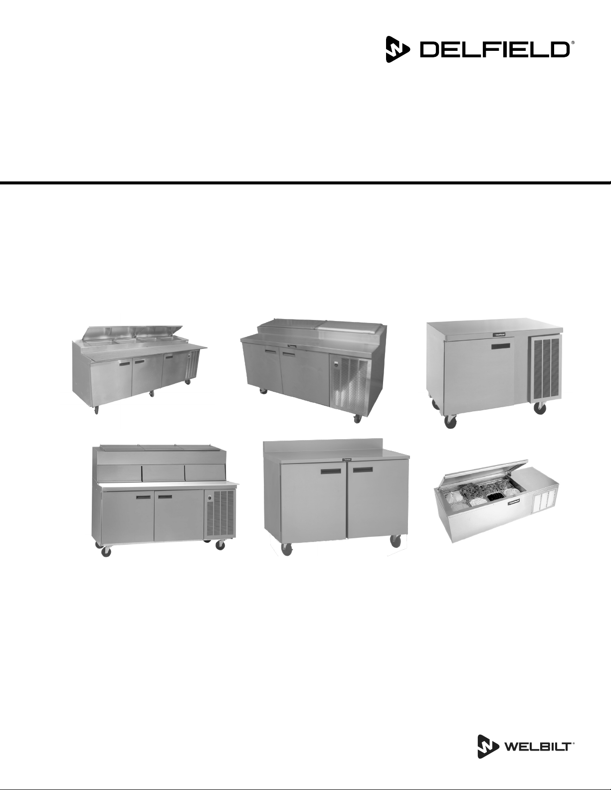
Model Numbers
This manual covers the following self contained work tables:
Standard Model Model with Export Option
Refrigerated Work Table With Backsplash
18648BSTMP 18648BST-E
18660BSTMP 18660BST-E
18672BSTMP 18672BST-E
18691BSTMP 18691BST-E
18699BSTMP 18699BST-E
186114BSTMP 186114BST-E
Refrigerated Work Table
18648BUCMP 18648BUC-E
18660BUCMP 18660BUC-E
18672BUCMP 18672BUC-E
18691BUCMP 18691BUC-E
18699BUCMP 18699BUC-E
186114BUCMP 186114BUC-E
Refrigerated Pizza Prep Table With Raised Rail
18648PTBMP 18648PTB-E
18660PTBMP 18660PTB-E
18672PTBMP 18672PTB-E
18691PTBMP 18691PTB-E
18699PTBMP 18699PTB-E
186114PTBMP 186114PTB-E
Refrigerated Pizza Prep Table With Dual LiquiTec® Rails
18648PDLV 18672PDLV -
Refrigerated Pizza Prep Table With LiquiTec® Rail
18648PTLV 18648PTL-E
18672PTLV 18672PTL-E
18699PTLV 18699PTL-E
Refrigerated Countertop Prep Rail
CTP8146-NB CTP8146-NB-E
CTP8160-NB CTP8160-NB-E
Serial Number Information
The serial number is on the identification plate that also
includes the model number.
• The id plate on all 18600 series units is located inside the
compressor section.
• The id plate on CTP-NB Series units is located on the front
of the unit.
Always have the serial number of your unit available
when calling for parts or service.
Warranty Information
Visit www.delfield.com/warranty to:
• Register your product for warranty.
• Verify warranty information.
• View and download a copy of your warranty.
Part Number: 9291455 08/17 5
Page 6
General Information Section 1
Regulatory Certifications
STANDARD MODELS
115Volt, 60Hertz, 1Phase models are certified by:
•
•
•
EXPORT OPTIONS
230-240Volt, 50Hertz, 1Phase models are certified by:
•
• Technical Inspection Association
• European Conformity
National Sanitation Foundation (NSF)
Underwriters Laboratories (UL)
Underwriters Laboratories of Canada (cUL)
National Sanitation Foundation (NSF)
6 Part Number: 9291455 08/17
Page 7
Section 2
Installation
DANGER
Installation must comply with all applicable fire and
health codes in your jurisdiction.
Caution
,
When adding any item verify the location of the
refrigeration lines on wrapped rail units. A refrigeration
leak in a rail may be irreparable or extremely difficult and
costly to repair.
Location
Warning
n
This equipment must be positioned so that the plug is
accessible unless other means for disconnection from the
power supply (e.g., circuit breaker or disconnect switch)
is provided.
Warning
n
Adequate means must be provided to limit the movement
of this appliance without depending on or transmitting
stress to the electrical conduit or gas lines.
The location selected for the equipment must meet the
following criteria. If any of these criteria are not met, select
another location.
• Units are intended for indoor use only.
• The location MUST be level, stable and capable of
supporting the weight of the equipment.
• The location MUST be free from and clear of combustible
materials.
• Equipment MUST be level both front to back and side to
side.
• Position the equipment so it will not tip or slide.
• Front casters MUST be locked once positioned.
• Recommended air temperature is 50° - 100°F
(10° - 38°C).
• Proper air supply for ventilation is REQUIRED AND
CRITICAL for safe and efficient operation.
• Do not obstruct the flow of ventilation air. Make sure the
air vents of the equipment are not blocked.
• Do not install the equipment directly over a drain. Steam
rising up out of the drain will adversely affect operation,
air circulation, and damage electrical / electronic
components.
Warning
n
To avoid instability the installation area must be capable
of supporting the combined weight of the equipment
and product. Additionally the equipment must be level
side to side and front to back.
Warning
n
This equipment is intended for indoor use only. Do not
install or operate this equipment in outdoor areas.
Part Number: 9291455 08/17 7
Page 8
Installation Section 2
Weight Of Equipment
Standard Model Model with Export
Option
Refrigerated Work Table With Backsplash
18648BSTMP 18648BST-E 390lbs (177kg)
18660BSTMP 18660BST-E 435lbs (197kg)
18672BSTMP 18672BST-E 495lbs (225kg)
18691BSTMP 18691BST-E 535lbs (243kg)
18699BSTMP 18699BST-E 594lbs (269kg)
186114BSTMP 186114BST-E 685lbs (310kg)
Refrigerated Work Table
18648BUCMP 18648BUC-E 390lbs (177kg)
18660BUCMP 18660BUC-E 435lbs (197kg)
18672BUCMP 18672BUC-E 495lbs (225kg)
18691BUCMP 18691BUC-E 535lbs (243kg)
18699BUCMP 18699BUC-E 594lbs (269kg)
186114BUCMP 186114BUC-E 685lbs (310kg)
Refrigerated Pizza Prep Table With Raised Rail
18648PTBMP 18648PTB-E 520lbs (236kg)
18660PTBMP 18660PTB-E 575lbs (260kg)
18672PTBMP 18672PTB-E 635lbs (288kg)
18691PTBMP 18691PTB-E 770lbs (350kg)
18699PTBMP 18699PTB-E 805lbs (365kg)
186114PTBMP 186114PTB-E 927lbs (420kg)
Refrigerated Pizza Prep Table With Dual LiquiTec® Rails
18648PDLV - 691lbs (313kg)
18672PDLV - 873lbs (396kg)
Refrigerated Pizza Prep Table With LiquiTec® Rail
18648PTLV 18648PTL-E 520lbs (236kg)
18672PTLV 18672PTL-E 635lbs (288kg)
18699PTLV 18699PTL-E 805lbs (365kg)
Refrigerated Countertop Prep Rail
CTP8146-NB CTP8146-NB-E 121lbs (55kg)
CTP8160-NB CTP8160-NB-E 158lbs (72kg)
Weight
Clearance Requirements
DANGER
Minimum clearance requirements are the same for
noncombustible locations as for combustible locations.
The flooring under the appliance must be made of a
noncombustible material.
DANGER
Risk of fire/shock. All minimum clearances must be
maintained. Do not obstruct vents or openings.
All Models Back / Sides 1.00” (25mm)
Rail Model Tops 14.00” (36cm)
Caster Model Bottoms 6.00” (15cm)
• Keep the vents clean and free of obstruction.
• Casters or legs must be used and not removed.
Dimensions
Model &
Export Option
Refrigerated Work Table With Backsplash
18648BSTMP
18648BST-E
18660BSTMP
18660BST-E
18672BSTMP
18672BST-E
18691BSTMP
18691BST-E
18699BSTMP
18699BST-E
186114BSTMP
186114BST-E
18648BUCMP
18648BUC-E
18660BUCMP
18660BUC-E
18672BUCMP
18672BUC-E
18691BUCMP
18691BUC-E
18699BUCMP
18699BUC-E
186114BUCMP
186114BUC-E
Refrigerated Pizza Prep Table With Raised Rail
18648PTBMP
18648PTB-E
18660PTBMP
18660PTB-E
18672PTBMP
18672PTB-E
18691PTBMP
18691PTB-E
18699PTBMP
18699PTB-E
186114PTBMP
186114PTB-E
Refrigerated Pizza Prep Table With Dual LiquiTec® Rails
18648PDLV 48.00”
18672PDLV 72.00”
Refrigerated Pizza Prep Table With LiquiTec® Rail
18648PTLV
18648PTL-E
18672PTLV
18672PTL-E
18699PTLV
18699PTL-E
CTP8146-NB
CTP8146-NB-E
CTP8160-NB
CTP8160-NB-E
Length Depth Height
48.00”
(122cm)
60.00”
(152cm)
72.00”
(183cm)
91.00”
(231cm)
99.00”
(251cm)
114.00”
(290cm)
Refrigerated Work Table
48.00”
(122cm)
60.00”
(152cm)
72.00”
(183cm)
91.00”
(231cm)
99.00”
(251cm)
114.00”
(290cm)
48.00”
(122cm)
60.00”
(152cm)
72.00”
(183cm)
91.00”
(231cm)
99.00”
(251cm)
114.00”
(290cm)
(122cm)
(183cm)
48.00”
(122cm)
72.00”
(183cm)
99.00”
(251cm)
Refrigerated Countertop Prep Rail
46.00”
(117cm)
60.00”
(152cm)
31.50”
(80cm)
31.50”
(80cm)
31.50”
(80cm)
31.50”
(80cm)
31.50”
(80cm) Plus 6”
(15cm) Cutting
Board
17.03”
(43cm)
40.00”
(102cm)
36.00”
(91cm)
42.00”
(107cm)
53.67”
(136cm)
42.00”
(107cm)
12.55”
(32cm)
8 Part Number: 9291455 08/17
Page 9

Section 2 Installation
Capacity
Door Size
19” (48cm) 27” (69cm) 32” (81cm)
Shelf Max Load 70lbs (32kg) 124lbs (56kg) 140lbs (64kg)
# Of Doors
Model &
Export Option
18648BSTMP
18648BST-E
18660BSTMP
18660BST-E
18672BSTMP
18672BST-E
18691BSTMP
18691BST-E
18699BSTMP
18699BST-E
186114BSTMP
186114BST-E
18648BUCMP
18648BUC-E
18660BUCMP
18660BUC-E
18672BUCMP
18672BUC-E
18691BUCMP
18691BUC-E
18699BUCMP
18699BUC-E
186114BUCMP
186114BUC-E
18648PTBMP
18648PTB-E
18660PTBMP
18660PTB-E
18672PTBMP
18672PTB-E
18691PTBMP
18691PTB-E
18699PTBMP
18699PTB-E
186114PTBMP
186114PTB-E
18648PDLV 12 1 1 3.95ft
18672PDLV 18 2 2 7.90ft
18648PTLV
18648PTL-E
18672PTLV
18672PTL-E
18699PTLV
18699PTL-E
# of 1/3 Size Pans
In Rail
19”
(48cm)
27”
(69cm)
32”
(81cm)
# Of Shelves Shelf Area Base Volume
Refrigerated Work Table With Backsplash
NA 1 1 3.95ft
NA 1 1 2 6.51ft
NA 2 2 7.90ft
NA 1 2 3 10.29ft
NA 3 3 11.85ft
NA 3 3 14.46ft
Refrigerated Work Table
NA 1 1 3.95ft
NA 1 1 2 6.51ft
NA 2 2 7.90ft
NA 1 2 3 10.29ft
NA 3 3 11.85ft
NA 3 3 14.46ft
Refrigerated Pizza Prep Table With Raised Rail
6 1 1 3.95ft
7 1 1 2 6.51ft
9 2 2 7.90ft
11 1 2 3 10.29ft
12 3 3 11.85ft
14 3 3 14.46ft
Refrigerated Pizza Prep Table With Dual LiquiTec® Rails
Refrigerated Pizza Prep Table With LiquiTec® Rail
6 1 1 3.95ft
9 2 2 7.90ft
12 3 3 11.85ft
2
(3670cm2) 9.36ft3 (265L)
2
(6048cm2) 13.81ft3 (391L)
2
(7339cm2) 16.52ft3 (468L)
2
(9560cm2) 22.35ft3 (633L)
2
(11009cm2) 25.07ft3 (427L)
2
(13434cm2) 30.16ft3 (854L)
2
(3670cm2) 10.25ft3 (290L)
2
(6048cm2) 15.10ft3 (428L)
2
(7339cm2) 18.04ft3 (511L)
2
(9560cm2) 24.44ft3 (692L)
2
(11009cm2) 27.31ft3 (773L)
2
(13434cm2) 33.00ft3 (934L)
2
(3670cm2) 9.36ft3 (265L)
2
(6048cm2) 13.81ft3 (391L)
2
(7339cm2) 16.52ft3 (468L)
2
(9560cm2) 22.35ft3 (633L)
2
(11009cm2) 25.07ft3 (427L)
2
(13434cm2) 30.16ft3 (854L)
2
(3670cm2) 8.41ft3 (238L)
2
(7339cm2) 15.42ft3 (437L)
2
(3670cm2) 9.36ft3 (265L)
2
(7339cm2) 16.52ft3 (168L)
2
(11009cm2) 25.07ft3 (710L)
Part Number: 9291455 08/17 9
Page 10

Installation Section 2
Model &
Export Option
Refrigerated Countertop Prep Rail
CTP8146-NB
CTP8146-NB-E
CTP8160-NB
CTP8160-NB-E
# of 1/3 Size Pans
In Rail
4 5
6 7
Adapter Bars
Electrical Service
DANGER
Check all wiring connections, including factory terminals,
before operation. Connections can become loose during
shipment and installation.
Warning
n
This appliance must be grounded and all field wiring must
conform to all applicable local and national codes. Refer
to rating plate for proper voltage. It is the responsibility of
the end user to provide the disconnect means to satisfy
the authority having jurisdiction.
• Plug units with R290 refrigerant into a receptacle that is a
minimum of 14” (36cm) above the floor.
• All electrical work, including wire routing and grounding,
must conform to local, state and national electrical codes.
• The equipment must be grounded.
• A separate fuse/circuit breaker must be provided for each
unit.
• The maximum allowable voltage variation is ±10% of the
rated voltage at equipment start-up (when the electrical
load is highest).
• If optional electrical receptacles are mounted in the unit’s
backsplash, they must be wired independently from the
existing unit wiring.
• Check all green ground screws, cables and wire
connections to verify they are tight before start-up.
Ground Fault Circuit Interrupter
Ground Fault Circuit Interrupter (GFCI/GFI) protection is a
system that shuts down the electric circuit (opens it) when it
senses an unexpected loss of power, presumably to ground.
Welbilt does not recommend the use of GFCI/GFI circuit
protection to energize our equipment. If code requires the
use of a GFCI/GFI then you must follow the local code. The
circuit must be dedicated, sized properly and there must
be a panel GFCI/GFI breaker. We do not recommend the
use of GFCI/GFI outlets to energize our equipment as they
are known for more intermittent nuisance trips than panel
breakers.
Model Amps H.P. NEMA Plug Voltage,
Hertz,
Phase
Refrigerated Work Table With Backsplash
18648BSTMP 2.9 0.20
18660BSTMP 2.9 0.20
18672BSTMP 2.9 0.20
18691BSTMP 4.8 0.25
18699BSTMP 4.8 0.25
186114BSTMP 6.3 0.33
Optional Export Refrigerated Work Table With Backsplash
18648BST-E 2.5 1/4
18660BST-E 2.8 1/3
18672BST-E 5.3 1/2
18691BST-E 5.3 1/2
18699BST-E 5.3 1/2
186114BST-E 5.0 3/4
Refrigerated Work Table
18648BUCMP 2.9 0.20
18660BUCMP 2.9 0.20
18672BUCMP 4.8 0.20
18691BUCMP 4.8 0.25
18699BUCMP 4.8 0.25
186114BUCMP 6.3 0.33
Optional Export Refrigerated Work Table
18648BUC-E 2.5 1/4
18660BUC-E 2.8 1/3
18672BUC-E 5.3 1/2
18691BUC-E 5.3 1/2
18699BUC-E 5.3 1/2
186114BUC-E 5.0 3/4
Refrigerated Pizza Prep Table With Raised Rail
18648PTBMP 4.7 0.25
18660PTBMP 4.7 0.25
18672PTBMP 6.5 (2) .20
18691PTBMP 6.5 (2) .20
18699PTBMP 6.5 (2) .20
186114PTBMP 6.5 (2) .20
Optional Export Refrigerated Pizza Prep Table With Raised Rail
18648PTB-E 2.5 1/4
18660PTB-E 2.8 1/3
18672PTB-E 5.3 1/2
18691PTB-E 5.3 1/2
18699PTB-E 5.3 1/2
186114PTB-E 5.0 3/4
Refrigerated Pizza Prep Table With Dual LiquiTec® Rails
18648PDLV 10.1 1/5, 1/3 5-20P 115, 60, 1
18672PDLV 12.7 1/5, 1/2 5-20P 115, 60, 1
Refrigerated Pizza Prep Table With LiquiTec® Rail
18648PTLV 7.0 1/4 5-15P 115, 60, 1
18672PTLV 14.0 1/2 5-20P 115, 60, 1
18699PTLV 14.0 1/2 5-20P 115, 60, 1
Optional Export Refrigerated Pizza Prep Table With LiquiTec® Rail
18648PTL-E
18672PTL-E
18699PTL-E
2.5 1/4
5-15P 115, 60, 1
Varies Per
Destination
5-15P 115, 60, 1
Varies Per
Destination
5-15P 115, 60, 1
Varies Per
Destination
Varies Per
Destination
230-240,
230-240,
230-240,
230-240,
50, 1
50, 1
50, 1
50, 1
10 Part Number: 9291455 08/17
Page 11

Section 2 Installation
Model Amps H.P. NEMA Plug Voltage,
Hertz,
Phase
Refrigerated Countertop Prep Rail
CTP8146-NB 3.7 1/5 5-15P 115 ,60, 1
CTP8160-NB 3.7 1/5 5-15P 115, 60, 1
Optional Export Refrigerated Countertop Prep Rail
CTP8146-NB-E
CTP8160-NB-E
2.5 1/4
Varies Per
Destination
230-240,
50, 1
Drain Connections
Self-contained work tables come standard with a condensate
evaporator. If the condensate evaporator fails, the unit’s
drain must have an outlet to an appropriate drainage area or
container.
A refrigerated rail will have a 1” (25mm) drain which will
need to be run to an appropriate floor drain or container.
The drain will be stubbed to the bottom of the machine
compartment. Either run drain to a floor drain or add a valve
to the base of the machine compartment and drain the rail
to a container when convenient.
Warning
n
Moisture collecting from improper drainage can create a
slippery surface on the floor and a hazard to employees.
It is the owner’s responsibility to provide a container or
outlet for drainage.
Leg & Caster Installation
DANGER
Legs or casters must be installed and the legs or casters
must be screwed in completely to prevent bending. When
casters are installed the mass of this unit will allow it to
move uncontrolled on an inclined surface. These units
must be tethered/secured to comply with all applicable
codes.
Warning
n
The unit must be installed in a stable condition with
the front wheels locked. Locking the front casters after
installation is the owner’s and operator’s responsibility.
Leveling
After the cabinet has been placed in the desired location,
cabinets with legs must be leveled. Level units from front to
back and from side to side. Leveling will insure proper door
operation and removal of condensate. Cabinets with casters
must have the caster brake set so the cabinet cannot move.
Stabilizing
It is very important that all legs are properly adjusted to keep
the cabinet level, evenly distribute the weight and to make
sure the unit will not rock, lean or be unstable.
Part Number: 9291455 08/17 11
Page 12

Installation Section 2
Refrigeration
BTU System
Model
Refrigerated Work Table With Backsplash R290
18648BSTMP 1550 NA 384 NA 150g
18660BSTMP 1550 NA 456 NA 150g
18672BSTMP 1550 NA 501 NA 150g
18691BSTMP 2440 NA 726 NA 150g
18699BSTMP 2440 NA 771 NA 150g
186114BSTMP 2936 NA 854 NA 150g
Optional Export Refrigerated Work Table With
18648BST-E 475 NA 1462 NA 454g
18660BST-E 686 NA 1462 NA 680g
18672BST-E 856 NA 2261 NA 1134g
18691BST-E 1169 NA 2261 NA 1134g
18699BST-E 1220 NA 2591 NA 1134g
186114BST-E 1373 NA 2591 NA 1361g
18648BUCMP 1550 NA 384 NA 150g
18660BUCMP 1550 NA 456 NA 150g
18672BUCMP 1550 NA 501 NA 150g
18691BUCMP 2440 NA 726 NA 150g
18699BUCMP 2440 NA 771 NA 150g
186114BUCMP 2936 NA 854 NA 150g
Optional Export Refrigerated Work Table R404A
18648BUC-E 475 NA 1462 NA 454g
18660BUC-E 686 NA 1462 NA 680g
18672BUC-E 856 NA 2261 NA 1134g
18691BUC-E 1169 NA 2261 NA 1134g
18699BUC-E 1220 NA 2591 NA 1134g
186114BUC-E 1373 NA 2591 NA 1361g
Refrigerated Pizza Prep Table With Raised Rail R290
18648PTBMP 2128 1037 356 253 150g
18660PTBMP 2128 1230 421 354 150g
18672PTBMP 1648 1158 367 476 (2) 150g
18691PTBMP 1705 1199 531 608 (2) 150g
18699PTBMP 1922 1336 561 658 (2) 150g
186114PTBMP 1922 1405 616 750 (2) 150g
Optional Export Refrigerated Pizza Prep Table With
18648PTB-E 470 441 2001 952 454g
18660PTB-E 694 617 2409 1208 680g
18672PTB-E 776 794 2967 1587 1134g
18691PTB-E 1062 1058 3537 1865 1134g
18699PTB-E 1144 1147 3537 1945 1134g
186114PTB-E 1297 1323 5169 2433 1361g
Refrigerated Pizza Prep Table With Dual LiquiTec® Rails R404A
18648PDLV 1453 1778 272 1058 16oz &
18672PDLV 1453 2876 359 1587 16oz &
Refrigerated Pizza Prep Table With LiquiTec® Rail R404A
18648PTLV 2220 1132 293 529 16oz
18672PTLV 3455 2021 396 794 32oz
18699PTLV 4456 2433 598 1058 32oz
Capacity
Base Rail Base Rail
Backsplash
Refrigerated Work Table R290
Raised Rail
Heat of
Rejection
Charge
R404A
R404A
24oz
32oz
BTU System
Model
Optional Export Refrigerated Pizza Prep Table With
18648PTL-E 470 441 2001 952 454g
18672PTL-E 776 794 2967 1587 1134g
18699PTL-E 1144 1147 3537 1945 1134g
Refrigerated Countertop Prep Rail R404A
CTP8146-NB NA 523 NA 305 6 oz.
CTP8160-NB NA 653 NA 462 7.1 oz
Optional Export Refrigerated Countertop Prep Rail R404A
CTP8146-NB-E NA 305 NA 523 454g
CTP8160-NB-E NA 462 NA 653 454g
Capacity
Base Rail Base Rail
LiquiTec® Rail
Heat of
Rejection
Charge
R404A
12 Part Number: 9291455 08/17
Page 13

Section 2 Installation
18600PTB Cutting Board Installation
1. Orient each bracket with a bend at the back and the
other to the outside.
2. Place each bracket back against the rail and flush against
the outside edge.
3. Mark the bracket hole locations.
4. Drill each 0.125” hole.
5. Secure each bracket to the Pizza Table with four 0.125”
pop rivets.
6. Slide the cutting board into the brackets.
Part Number: 9291455 08/17 13
Page 14

Installation Section 2
THIS PAGE INTENTIONALLY LEFT BLANK
14 Part Number: 9291455 08/17
Page 15

Section 3
Operation
DANGER
The on-site supervisor is responsible for ensuring that
operators are made aware of the inherent dangers of
operating this equipment.
DANGER
Do not operate any appliance with a damaged cord or
plug. All repairs must be performed by a qualified service
company.
DANGER
Never stand on the unit! They are not designed to hold
the weight of an adult, and may collapse or tip if misused
in this manner.
DANGER
Keep power cord AWAY from HEATED surfaces. DO NOT
immerse power cord in water. DO NOT let power cord
hang over edge of table or counter.
Warning
n
Damp or wet hands may stick to cold surfaces.
Caution
,
Overloading the storage area, restricting the air flow, and
continuous opening and closing of the doors and drawers
will hamper the units ability to maintain operational
temperature.
Caution
,
Do not throw items into the display case or storage area.
Failure to heed this recommendation could result in
damage to the interior of the cabinet or to the blower
coil.
Warning
n
Do not contact moving parts.
Warning
n
The operator of this equipment is solely responsible
for ensuring safe holding temperature levels for all
food items. Failure to do so could result in unsafe food
products for customers.
Warning
n
Do not use electrical appliances or accessories other than
those supplied by the manufacturer.
Warning
n
All covers and access panels must be in place and properly
secured, before operating this equipment.
Warning
n
Do not block the supply and return air grills or the air
space around the air grills. Keep plastic wrappings,
paper, labels, etc. from being airborne and lodging in
the grills. Failure to keep the air grills clear will result in
unsatisfactory operation of the system.
Part Number: 9291455 08/17 15
Page 16

Operation Section 3
CTP-NB Series, Countertop Prep Rail
115V & 230-240V
The unit is equipped with one On/Off switch located on
the right end of the unit. The unit’s compressor will begin
operating when this switch is turned to the On position.
Temperature ranges for the rail are 33°F to 41°F (1°C to 5°C).
A minimum of one hour of off time per day with the pans
removed from the rail is required to properly defrost the rail.
Refrigerated Work Tables
Delfield refrigerated bases are designed to maintain an
operational temperature of 36°F to 40°F (2°C to 4°C). Selfcontained units with a cord and plug have an ON/OFF switch
located directly behind the louvered panel covering the
compressor section. Simply turn the switch to ON to begin
operation.
REFRIGERATED RAILS
Temperature in the refrigerated rail is designed to maintain
33°F to 41°F (0°C to 5°C). An ON/OFF switch is also provided
for the rail; it shuts off the rail only.
Product in the rail should be moved to the refrigerated base
at the end of the day. This allows you to turn the rail off at
night to save energy and time to defrost as needed. It also
helps maintain product quality. A minimum of one hour of off
time per day with the pans removed from the rail is required
to properly defrost the rail.
These units are not designed to cool warm food products.
Items should be placed in the unit cooled at least to the
desired holding temperature, if not slightly colder. Fill pan
to 2.0” (5cm) below top of cold pan. In some applications,
a gradual warming of product may occur, particularly at
the exposed top of the products. Stirring or rotation of the
product is necessary to maintain overall temperature.
Warming of food product can occur very quickly outside
of the unit. When loading or rotating the product, avoid
leaving food items in a non-refrigerated location for any
length of time to prevent warming or spoilage. To ensure
product quality product must be rotated every four hours.
Always place covers on pans when not serving to maintain
temperatures.
Air from air vents can affect the temperature in the cold
pans. Add deflectors to vents to redirect airflow.
Work Table Evaporator Fan Operation
When the refrigerator is initially powered up or immediately
following a power outage the unit will begin cooling after a
3-6 minute delay. During normal operation the evaporator
fan pulses independently of the compressor as dictated by
the controller as follows:
1. During the cooling mode, compressor and evaporator
fan run simultaneously.
2. During the compressor off mode, evaporator fan pulses
three minutes on and three minutes off.
3. During an actual defrost event other than the off-cycle
defrost, compressor stays off but the evaporator fan
runs continuously.
Cooling Cycle Defrost Cycle
Compressor On Compressor Off Compressor Off
Evaporator Fan On Evap Fan Cycles On
3-Min, Off 3-Min
Evaporator Fan On
PTLV Pressure Control
Refrigerated pizza prep tables with LiquiTec® rails have a
high pressure limiting device. Under severe overloading
conditions, or in the event of a condenser fan failure or a
plugged or blocked condenser, this device may shut down
the refrigeration system. This device will automatically reset,
but determining the cause of the high pressure condition
should be investigated by a qualified refrigeration technician.
Caution
,
In attempting to adjust the pressure control, you can
do damage to your unit. Please contact KitchenCare +1
(844) 724-2273 or your local service agent. Delfield is
not responsible for charges incurred while having the
pressure control adjusted.
Factory Recommended Settings
Cut-in 20#
Cut-out 5#
Differential 15#
PTLV Pressure Control
16 Part Number: 9291455 08/17
Page 17

Section 3 Operation
115Volt Work Table Control Assemblies
• Controls are located in the mechanical section behind a
louvered panel.
• The rail power switch is accessible through a hole in the
louvered panel.
Notice
Rail temperature displayed is for refrigeration set point
purposes only. Display does not reflect air or product
temps in unit.
Unit Power Switch
Base
Temperature
Control
Control Assembly For BSTMP Series & BUCMP Series,
Work Table With Or W/o Backsplash
Rail Power
Switch
Rail
Temperature
Control
Control Assembly For PTBMP Series & PTLV Series,
Refrigerated Pizza Prep Table With Raised or LiquiTec® Rail
Unit Power Switch
Base Temperature
Control
AT S TA R T U P
1. At initial start-up or anytime power is disconnected, then
reconnected to the unit, the control will go into defrost
mode.
2. The control will enter a DEFROST mode and the display
will read dEF. The compressor and condenser fan as well
as the evaporator fan will remain off until this initial
defrost is complete. This initial defrost cycle may take up
to 35 minutes to complete.
3. The display will continue to read dEF for an additional 30
minutes while the cooling cycle cools the box to the set
temperature.
4. Then the digital thermostat will display box temperature.
5. The temperature control will cycle the compressor,
evaporator fan motor and condenser fan motor to
maintain box temperature at the control setting. For
more information see Work Table Evaporator Fan
Operation on page 16.
Defrost
The temperature control also monitors the evaporator
temperature and will turn off the compressor and condenser
fan motor when needed to allow accumulated frost on the
evaporator to clear. During this defrost cycle, the digital
temperature display will read dEF. After the defrost cycle is
complete, the temperature control will return to a normal
cooling cycle, but the display will continue to read dEF until
the evaporator returns to normal cooling temperatures (up
to 30 minutes).
The electronic temperature controller monitors evaporator
temperature and compressor run time to determine the
proper time for a positive defrost cycle. A defrost cycle
can occur as often as every 60 minutes under extremely
heavy usage. It can last a minimum of 2 minutes. When the
controller enters the defrost mode the compressor is shut
off and will remain off until the evaporator coil temperature
exceeds 41°F (5°C) or the controller reaches a time limit of 75
minutes on a refrigerated unit.
Control Assembly For PDLV Series,
Refrigerated Pizza Prep Table With Dual LiquiTec® Rails
Part Number: 9291455 08/17 17
Page 18

Operation Section 3
ERC112 TEMPERATURE CONTROL
V
V
Operation / Indication
Status Displayed
Normal (°C) Temp. [°C] Unit depends on setting
Normal (°F) Temp. [°F]
Show set-point Temp.
Set to Defrost dEF / Temp Depends on setting
Sensor 1 defect E01 X Air sensor
Sensor 2 defect E02 X Coil sensor
Sensor 3 defect E03 X Open
Sensor 4 defect E04 X Open
High temperature alarm Hi X Automatically switching
Low temperature alarm Lo X
Line voltage too high uHi X
Line voltage too low uLi X
Control calls for cooling
for more than 24 hours
straight
LEA X
Comments
(parameters in control)
(parameters in control
or as chosen by upper
left button)
at 2 sec rate
Time includes defrost.
Error will go away if the
control cycles off the
compressor or if the
power is shut off. If error
is on a cold pan it could
be related to a high
ambient temperature or
not shutting the rail off
nightly.
Press upper or lower right button.
• Display show actual set-point (blinking).
• If buttons untouched for 3 seconds returns to
normal.
• Increase set-point by pressing upper button. Max value
depends on parameters in control.
• Decrease set-point by pressing lower button. Min value
depends on parameters in control.
• If buttons untouched for 3 seconds returns to
normal and stores new set-point.
Press upper left button for 5 seconds.
• Start defrost.
Press lower left button for 5 seconds.
• Unit goes into stand-by mode.
• The display will read Off, then a period.
• Press the lower left button again for 5 seconds.
• The display will read On.
• The unit will then start up in the defrost mode,
and display will read dEF.
Temperature Alarm
The alarm will sound and flash HI or LO 90 minutes after the
unit has reached its alarm temperature point or after any
power interruption if the temperature is above or below the
alarm set points.
• The high refrigerator temperature point is 50°F (10°C).
• The low refrigerator temperature point is 25°F (-4°C).
18 Part Number: 9291455 08/17
Page 19

Section 3 Operation
CHANGING DISPLAY FROM FAHRENHEIT TO CELSIUS ON
ERC112 CONTROL
1. Simultaneously hold the up and down arrows for
5 seconds to access menu for password protected
parameters.
2. Screen should temporarily flash PAS and then move to a
numeric screen.
3. Scroll to 187 using the up/down arrows and push the
stand-by button (lower left button) to enter.
6. -F should be displayed indicating Fahrenheit. Use the
down arrow to change it to -C for Celsius and hit the
stand-by button (lower left button) to enter the change.
7. Push the defrost button (upper left button) to move out
of the display unit menu.
4. Scroll to dis using the up/down arrows and push the
stand-by button (lower left button) to enter into the
display menu.
5. Scroll to CFu using the up/down arrows and push the
stand-by button (lower left button) to enter the display
unit menu.
8. Push the defrost button (upper left button) to move out
of the display menu and back to the normal display.
NOTE: For steps 7 and 8, display will return back to normal
display after 30 seconds of inactivity.
Part Number: 9291455 08/17 19
Page 20

Operation Section 3
230-240Volt Export Work Table Controls
EXPORT TEMPERATURE CONTROL
A thermostat controls temperature in the BUC-E, BST-E,
PTB-E base, PTL-E base and rail. They are located in the
machine compartment.
• The thermostat is set at the factory to provide proper
operation at 2.5.
• To adjust the temperature, turn the knob clockwise as
indicated on the control. Settings are from 1 through 9 (9
being the coldest).
• Adjustments should be made gradually.
• Several small adjustments will be more effective than one
large adjustment.
• It may take an hour or longer to realize the temperature
change depending on the application and location of the
unit.
EXPORT 230-240 VOLT PRESSURE CONTROL
Temperature in the PTB-E rail is controlled by an adjustable
pressure control located in the machine compartment and
adjustable control has the word COLDER near the knob, with
an arrow to indicate the adjustment direction. This control is
field adjustable and does not require a service agent. If you
have any questions, call an authorized service agent.
In attempting to adjust the pressure control, you can do
damage to the unit by accidentally adjusting the differential.
NOTE: Delfield is not responsible for charges incurred while
adjusting the pressure control.
Factory settings are:
• 25 psi (207 kPa) differential
• 55 psi (552 kPa) cut-in
• 30 psi (345 kPa) cut-out
Cut In Knob
Controlled
Dierential
Thermostat Dial
PTB-E & PTL-E HIGH PRESSURE LIMITING DEVICE
All R404A models have a high pressure limiting device. Under
severe overloading conditions, or in the event of a condenser
fan failure or a plugged or blocked condenser, this device
may shut down the refrigeration system. This device will
automatically reset, but determining the cause of the high
pressure condition should be investigated by a qualified
refrigeration technician.
20 Part Number: 9291455 08/17
Page 21

Section 4
Maintenance
DANGER
It is the responsibility of the equipment owner to perform
a Personal Protective Equipment Hazard Assessment
to ensure adequate protection during maintenance
procedures.
DANGER
Failure to disconnect the power at the main power supply
disconnect could result in serious injury or death. The
power switch DOES NOT disconnect all incoming power.
Caution
,
Over shelves and other items mounted to the top of the
counters should never be installed in the field due to the
potential damage to the refrigeration system.
Caution
,
Maintenance and servicing work other than cleaning as
described in this manual must be done by an authorized
service personnel.
DANGER
Disconnect electric power at the main power disconnect
for all equipment being serviced. Observe correct polarity
of incoming line voltage. Incorrect polarity can lead to
erratic operation.
Warning
n
When cleaning interior and exterior of unit, care should
be taken to avoid the front power switch and the rear
power cord. Keep water and/or cleaning solutions away
from these parts.
Warning
n
Never use sharp objects or tools to remove ice or frost. Do
not use mechanical devices or other means to accelerate
the defrosting process.
General Cleaning
Warning
n
When using cleaning fluids or chemicals, rubber gloves
and eye protection (and/or face shield) must be worn.
Notice
Never use a high-pressure water jet for cleaning or hose
down or flood interior or exterior of units with water. Do
not use power cleaning equipment, steel wool, scrapers
or wire brushes on stainless steel or painted surfaces.
You are responsible for maintaining the equipment
in accordance with the instructions in this manual.
Maintenance procedures are not covered by the warranty.
Maintenance Daily Weekly Monthly After Prolonged
Shutdown
Interior X X X
Gasket X X X
Exterior X X X
Drain X X X
Drawers/Door X X X
Condenser Coil X X X
Part Number: 9291455 08/17 21
At Start-Up
Page 22

Maintenance Section 4
Interior Cleaning
The interior can be cleaned using soap and warm water. If
this isn’t sufficient, try ammonia and water or a nonabrasive
liquid cleaner.
GASKETS
Gaskets require regular cleaning to prevent mold and mildew
build up and also to retain the elasticity of the gasket. Clean
them with water and mild soap (not citrus based). Avoid full
strength cleaning products on gaskets as this can cause them
to become brittle and crack. Never use sharp tools or knives
to scrape or clean the gasket. Gaskets can be easily replaced
and do not require the use of tools or an authorized service
person. The gaskets are dart style and can be pulled out of
the groove in the door. Place gasket in warm water to make
the material more pliable for installation. Dry and press into
place.
PREVENTING BLOWER COIL CORROSION
To help prevent corrosion of the blower coil, store all acidic
items, such as pickles and tomatoes, in seal-able containers.
Immediately wipe up all spills.
Exterior Cleaning
Notice
Never use an acid based cleaning solution on exterior
panels! Many food products have an acidic content,
which can deteriorate the finish. Be sure to clean the
stainless steel surfaces of ALL food products.
Clean the area around the unit as often as necessary to
maintain cleanliness and efficient operation.
Wipe surfaces with a damp cloth rinsed in water to remove
dust and dirt from the outside of the unit. Always rub with
the “grain” of the stainless steel to avoid marring the finish.
If a greasy residue persists, use a damp cloth rinsed in a mild
dish soap and water solution. Wipe dry with a clean, soft
cloth.
Never use steel wool or abrasive pads for cleaning. Never use
chlorinated, citrus based or abrasive cleaners.
Stainless steel exterior panels have a clear coating that
is stain resistant and easy to clean. Products containing
abrasives will damage the coating and scratch the panels.
Daily cleaning may be followed by an application of stainless
steel cleaner which will eliminate water spotting and
fingerprints. Early signs of stainless steel breakdown are
small pits and cracks. If this has begun, clean thoroughly and
start to apply stainless steel cleaners in attempt to restore
the steel.
Wipe casters with a damp cloth to prevent corrosion.
DRAIN
Drains can become loose or disconnected during normal use.
Be sure all drain lines are free of obstructions.
22 Part Number: 9291455 08/17
Page 23

Section 4 Maintenance
Drawer Assembly Cleaning
The drawer assembly is designed to be cleaned easily. Both
drawer and tracks are removable without tools. The drawer
tracks are dishwasher safe or can be cleaned in a sink with
detergents and a soft bristle brush. Drawers and tracks
should be cleaned on a weekly basis.
Remove Drawers
Pull the drawer box out until it stops. Lift up on the drawer
front and pull the drawer box completely out. Using a soft
bristle brush, clean the track on the bottom of the drawer
box. When finished, it should be wiped clean of all food and
debris.
Tracks
The drawer box assembly must be removed. Pull the drawer
tracks out until they hit a stop. Locate blue safety clips
towards the back of each drawer track. Blue safety clips have
a tab on the top. Push the tab back until it clicks. Lift up and
pull the drawer tracks all the way out of the drawer cage.
The drawer tracks are
dishwasher safe or can
be cleaned in a sink with
detergents and a soft
tab on top of blue
safety clip
basis. Using a soft bristle brush, wash the track making sure
each roller is thoroughly cleaned. The drawer cage should
be cleaned with a soft bristle brush, removing any food and
debris gathered on the bottom ledge. Once it’s cleaned
thoroughly with a soft bristle brush, wipe remaining debris
clean with a soft towel.
Reassembly
Push the drawer tracks into the drawer cage. The blue safety
clip must remain pushed towards the back. Lift up and slide
the drawer track all the way into the drawer cage. The blue
safety clip will lock in place automatically. Once all tracks are
replaced, insert the drawer box. Rest the drawer box bottom
track on the front track roller. Then push the drawer back
in place SLOWLY. When the drawer box is about half way in
you will hit a STOP. You must lift the front of the drawer up
approximately ½” (1.3cm) to continue inward. Clean tracks as
often as possible. The cleaner the tracks are the better they
will operate.
bristle brush. Drawers
and tracks should be
cleaned on a weekly
Doors
Over time and with heavy-use doors, the hinges may become
loose. If this happens, tighten the screws that mount the
hinge brackets to the frame of the unit. Loose or sagging
doors can cause the hinges to pull out of the frame, which
may damage both the doors and the hinges. In some cases
this may require qualified service agents or maintenance
personnel to perform repairs.
Cleaning The Condenser Coil
In order to maintain proper refrigeration performance, the
condenser fins must be cleaned of dust, dirt and grease
regularly. It is recommended that this be done monthly. If
conditions are such that the condenser is totally blocked
in a month, the frequency of cleaning should be increased.
Clean the condenser with a vacuum cleaner or stiff brush. If
extremely dirty, a commercially available condenser cleaner
may be required.
Failure to maintain a clean condenser coil can initially cause
high temperatures and excessive run times. Continuous
operation with a dirty or clogged condenser coil can result in
compressor failure. Neglecting the condenser coil cleaning
procedures will void any warranties associated with the
compressor and cost to replace the compressor.
Part Number: 9291455 08/17 23
Page 24

DELFIELD
980 SOUTH ISABELLA ROAD, MOUNT PLEASANT, MI 48858
WWW.DELFIELD.COM
800-733-8821
WWW.WELBILT.COM
Welbilt provides the world’s top chefs, and premier chain operators or growing independents with industry leading equipment and soluons.
Our cung-edge designs and lean manufacturing taccs are powered by deep knowledge, operator insights, and culinary experse.
All of our products are backed by KitchenCare® – our aermarket, repair, and parts service.
CLEVELAND
CONVOTHERM®
©2017 Welbilt Inc. except where explicitly stated otherwise. All rights reserved. Connuing product improvement may necessitate change of specicaons without noce.
Part Number: 9291455 08/17
DELFIELD®
FITKITCHEN™
FRYMASTER®
GARLAND
KOLPAK®
LINCOLN
MANITOWOC®
MERCO®
MERRYCHEF®
MULTIPLEX®
 Loading...