

Page 1

Delem
V0614, 1.1
DA-52s
Installation Manual
V 3
Page 2

Delem
V0614, 1.2
Preface
This manual contains information necessary for installation of a DA-52s control on a
pressbrake machine. It is meant for service people who are authorised for service and
installation of the machine.
Limited guarantee
• The equipment is supplied by Delem without safety features. The machine manufacturer
has to ensure a safe environment.
• This equipment must be installed and used in accordance with Delem's specifications.
The guarantee on the equipment is invalidated in the event of improper installation and/or
use of this equipment.
• The General Terms and Conditions of Delivery of Delem shall apply to this product.
These conditions are available from Delem on request.
• This manual does not entitle you to any rights. Delem reserves the right to change this
manual without prior warning.
• All rights reserved. The copyright is held by Delem. No part of this publication may be
copied or reproduced without written permission from Delem BV.
Version history
The control software is updated regularly to increase performance and add new functionality.
This manual is also updated as a result of changes in the control software. The following
overview shows the relation between software and manual versions.
Software version Manual version Description
V3 V0713 first issue V3
V3 V0813 update V3
V3 V0614 update V3
This manual is valid for software version 3.
Page 3

Delem
V0614, 1.3
Table of contents
PAR T I - HARDWARE DESCRIPTION .................................................................................. 5
1. INTRODUCTION ............................................................................................................ 6
2. SPECIFICATIONS .......................................................................................................... 7
2.1. Physical dimensions ................................................................................................ 7
2.2. Technical specifications .......................................................................................... 8
3. SYSTEM I/O ................................................................................................................... 9
3.1. Introduction ............................................................................................................. 9
3.2. Power supply ........................................................................................................ 10
3.3. USB connector ...................................................................................................... 10
3.4. Valve connector .................................................................................................... 11
3.5. Analog A ............................................................................................................... 12
3.6. Analog B ............................................................................................................... 13
3.7. Digital I/O .............................................................................................................. 13
3.8. Encoders ............................................................................................................... 16
4. SPARE PARTS ............................................................................................................ 17
4.1. Introduction ........................................................................................................... 17
5. SCHEMATICS .............................................................................................................. 18
PART II - MACHINE SETTINGS ............................................................................................ 1
1. THE MACH INE PARAMETE RS ..................................................................................... 2
1.1. Machine parameters menu ...................................................................................... 2
1.2. Update control ......................................................................................................... 3
1.2.1. Update procedure ............................................................................................ 3
1.2.2. Backup/restore the application ........................................................................ 7
1.2.3. Modify the update ............................................................................................ 8
1.3. Option installation ................................................................................................. 10
1.3.1. Request option on the control ........................................................................ 10
1.3.2. Request option code at Delem ...................................................................... 13
2. WINDOWS TASKS ...................................................................................................... 16
2.1. Windows introduction ............................................................................................ 16
2.2. Directory structure ................................................................................................. 18
2.3. Important files ....................................................................................................... 19
2.4. Editing the autoexec.bat ........................................................................................ 23
2.5. Control Rescue procedure .................................................................................... 25
2.6. Sequencer adjustment .......................................................................................... 29
2.7. Analysis program .................................................................................................. 31
PART III - THE DIAGNOSTIC PROGRAM ............................................................................. 1
1. GENERAL REMARKS ................................................................................................... 2
1.1. Valve outputs .......................................................................................................... 2
1.2. Components check ................................................................................................. 2
Page 4

Delem
V0614, 1.4
2. TEST-MENU ................................................................................................................... 3
2.1. Start diagnostic mode ............................................................................................. 3
2.2. The menu ................................................................................................................ 3
3. KEY TEST ...................................................................................................................... 4
4. SCREEN TEST............................................................................................................... 5
5. I/O TEST......................................................................................................................... 7
5.1. Test screen ............................................................................................................. 7
5.2. Testing the valve deflection ..................................................................................... 9
APP E N DIX A - REFERE NCE L IST ........................................................................................ 1
Page 5

Delem
V0614, 1.5
Part I - Hardware description
This section contains the hardware specifications of a Delem control DA-52s.
Page 6
Delem
V0614, 1.6
1. Introduction
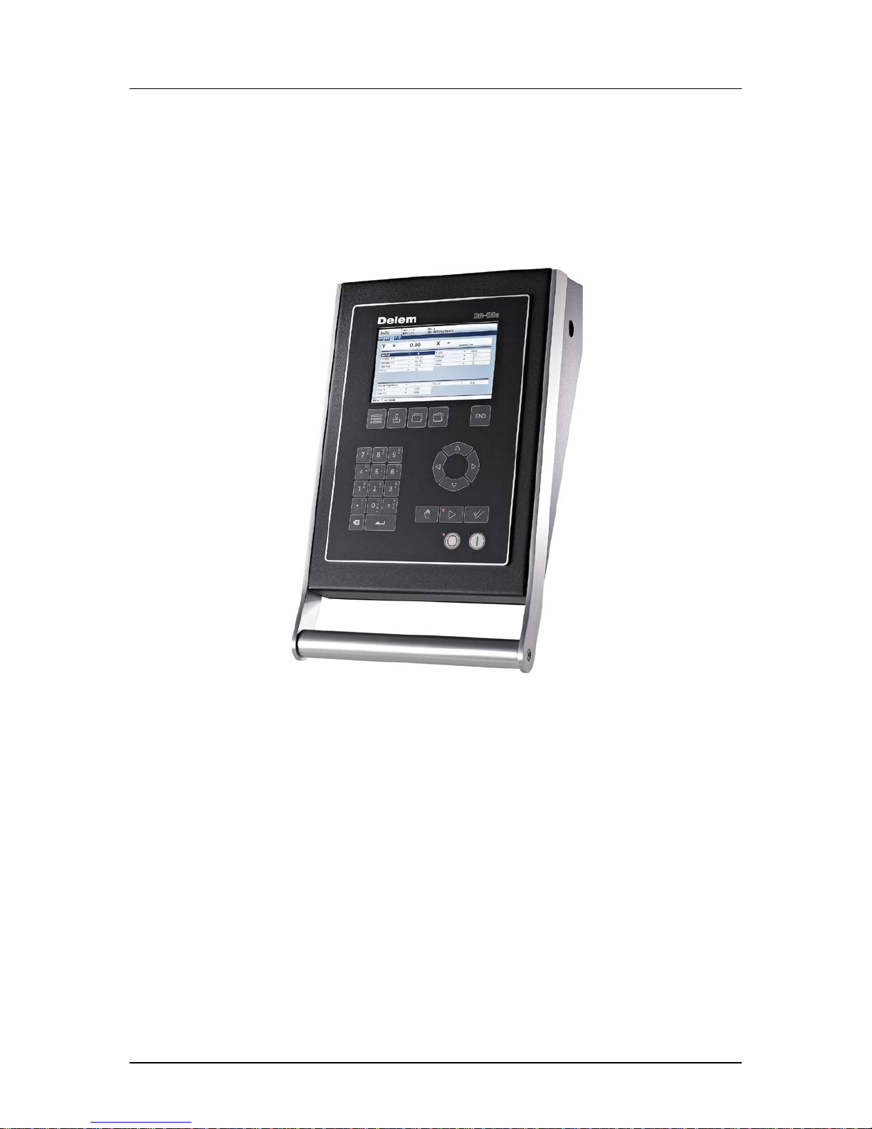
This manual contains information necessary for installation of a DA-52s control. Such a
control is the heart of a pressbrake control system with which a pressbrake machine is
controlled.
Figure 1.a
A DA-52s control combines different tasks in one unit:
- programming products and tools;
- axis control during bending;
- adjustment of machine settings.
Product programming and control operation is described in the user manual [3] of the control.
Page 7

Delem
V0614, 1.7
2. Specifications
2.1. Physical dimensions
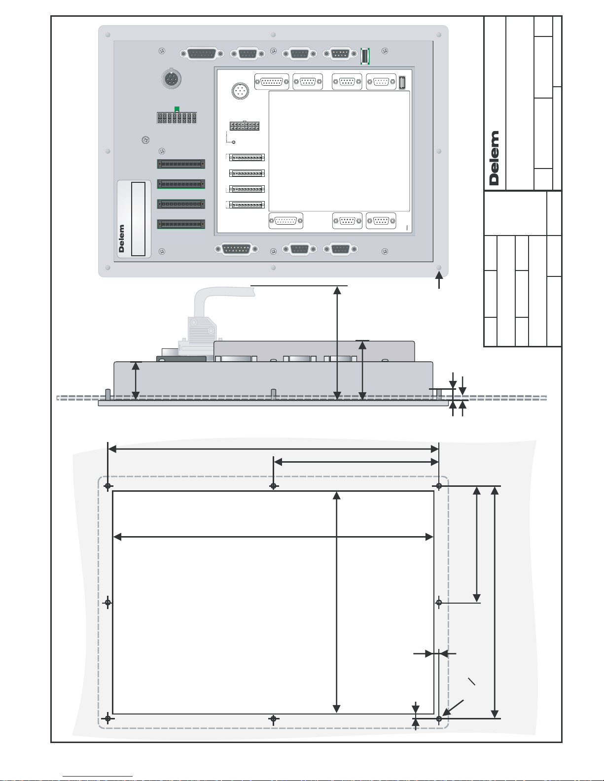
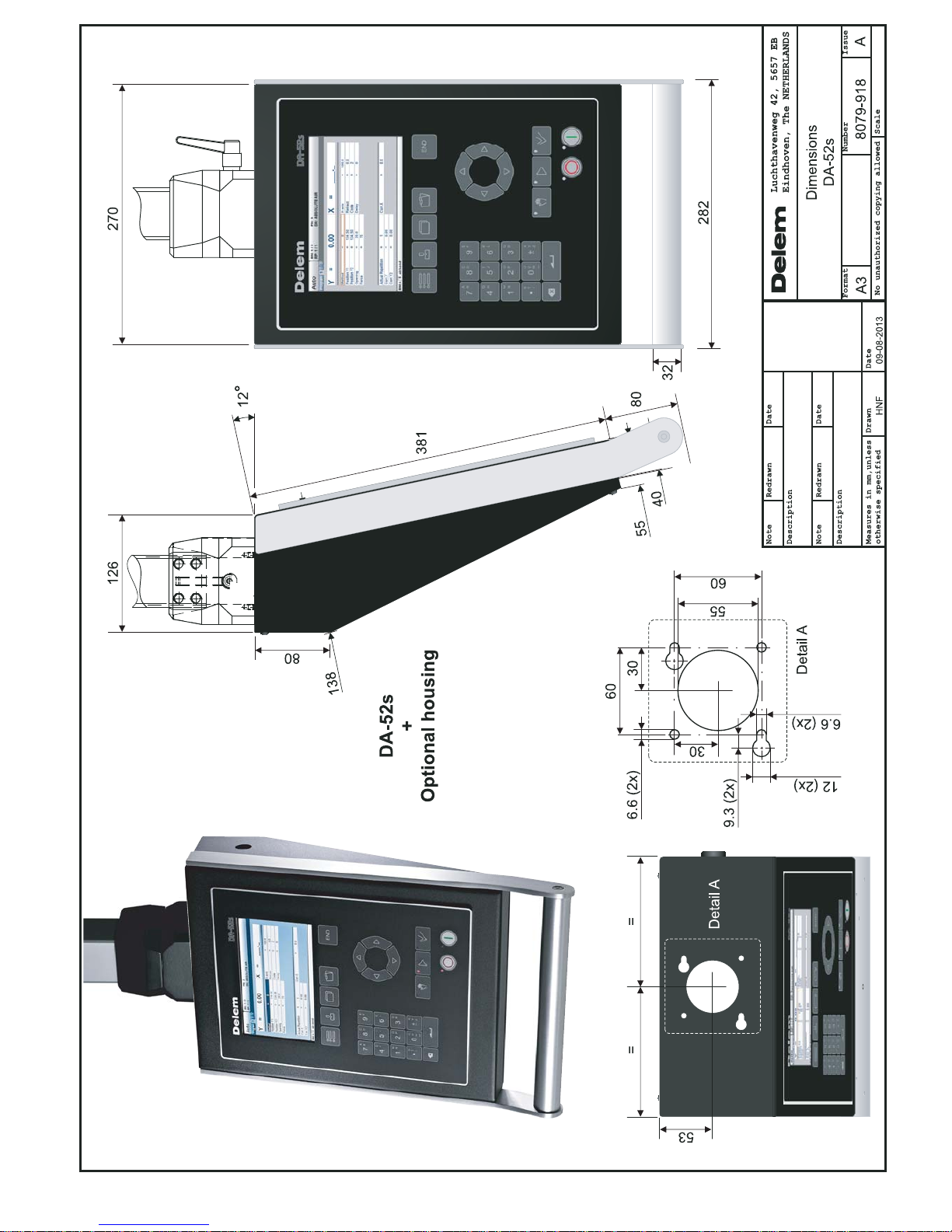
For the dimensions of the DA-52s control, see the included drawings at the end of this
section.
The following environment specification values are valid for a DA-52s control:
Ambient temperature
5 - 45°C
Warning:
Avoid long-term exposure of the control to direct
sunlight. Otherwise, the temperature inside the
control will rise above tolerance levels.
Operation of the control should be carried out
indoors.
Storage temperature
min. -20°C
max. 70°C
Relative humidity
max. 90 % non-condensing
EMC
designed and built to meet the following standards:
EN50081-2
EN60082-2
Enclosure
designed and built to meet the following standards:
IP20 (without optional enclosure)
IP54 (with optional enclosure)
Page 8

Delem
V0614, 1.8
2.2. Technical specifications
Power supply
18 - 28 VDC
80 W
Display
LCD/TFT colour
7” Widescreen
800 x 480
Interfaces
Valve connector
(see chapter 3)
Analog A/B
4 x Encoder
1 x RS-232
1 x USB
digital I/O
Memory
Flash memory, 64 MB embedded
Page 9
Delem
V0614, 1.9
3. System I/O
3.1. Introduction
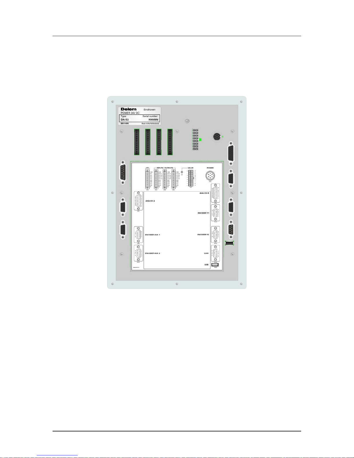
Figure 3.a
The DA-52s control is equipped with a large set of connectors for various functions:
- valve control
- system I/O
- encoder feedback
- communication
- USB
The various connectors are discussed in the following sections.
Warning:
Connectors may not be plugged or unplugged when power is ON. Connectors may only be
connected or disconnected when power is OFF.
The only exception to this rule is the USB connector.
Page 10
Delem
V0614, 1.10
3.2. Power supply
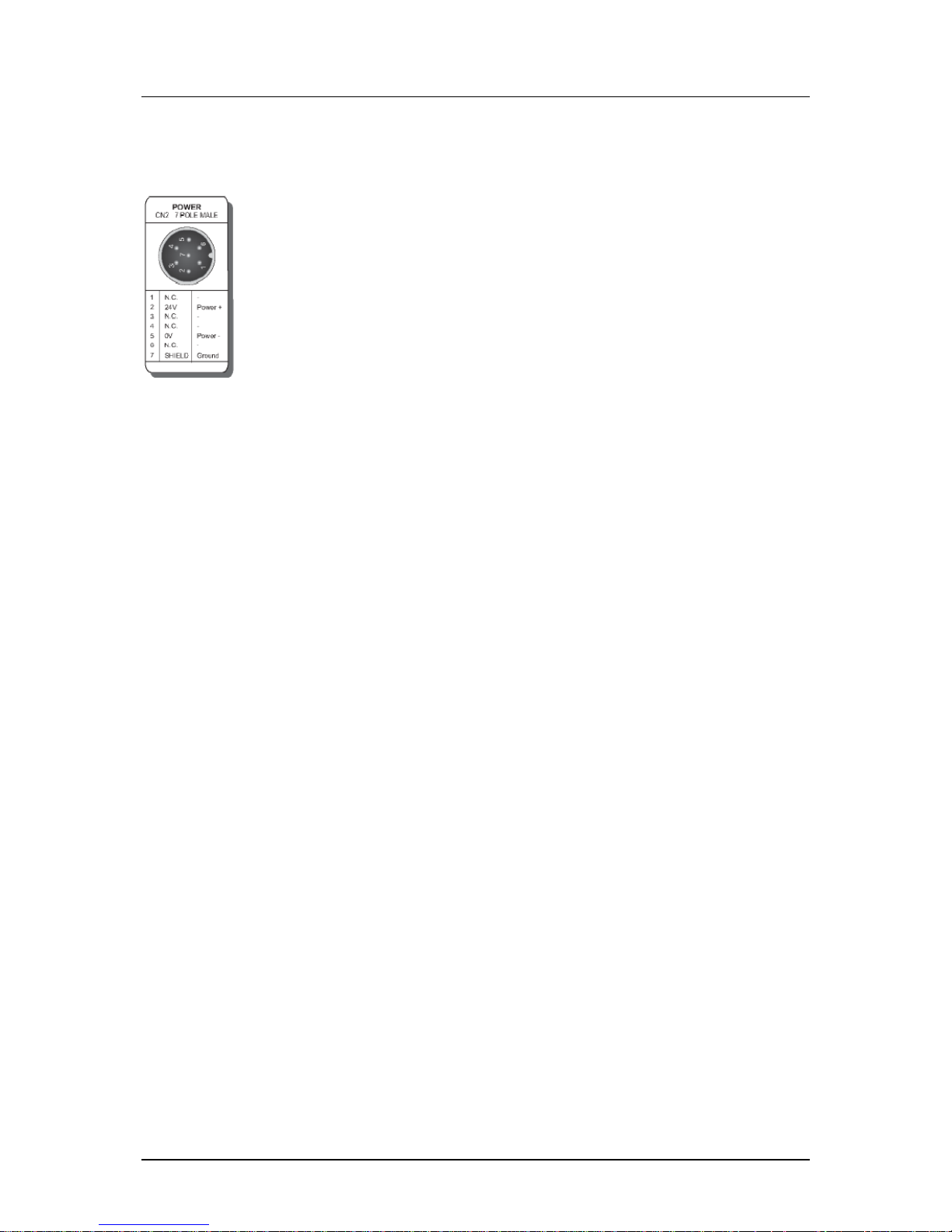
7-pole male binder connector
3.3. USB connector
The control has been equipped with one standard USB connector, according to the USB 1.1
specification.
Page 11
Delem
V0614, 1.11
3.4. Valve connector
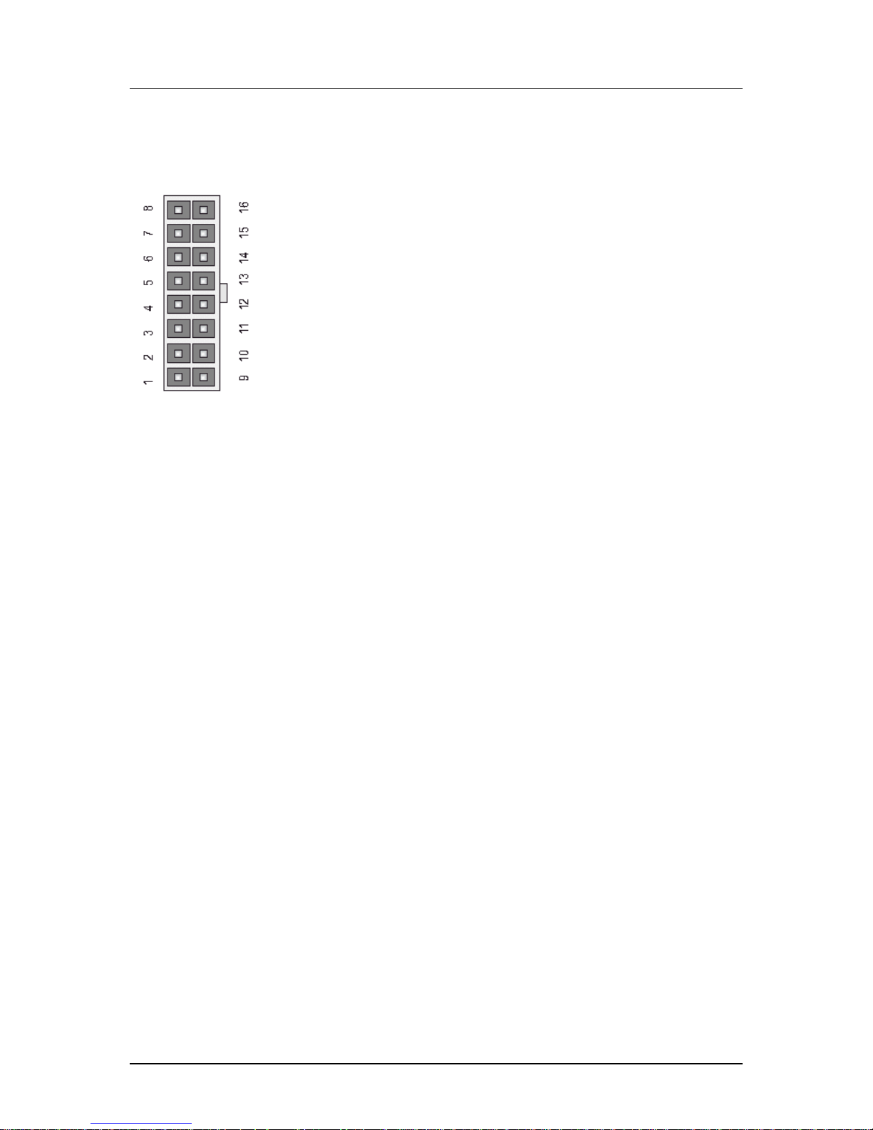
16-pin connector for valve control.
Standard: P-VA
The connector is used for pressure valve control. The control signals for the valve amplifiers
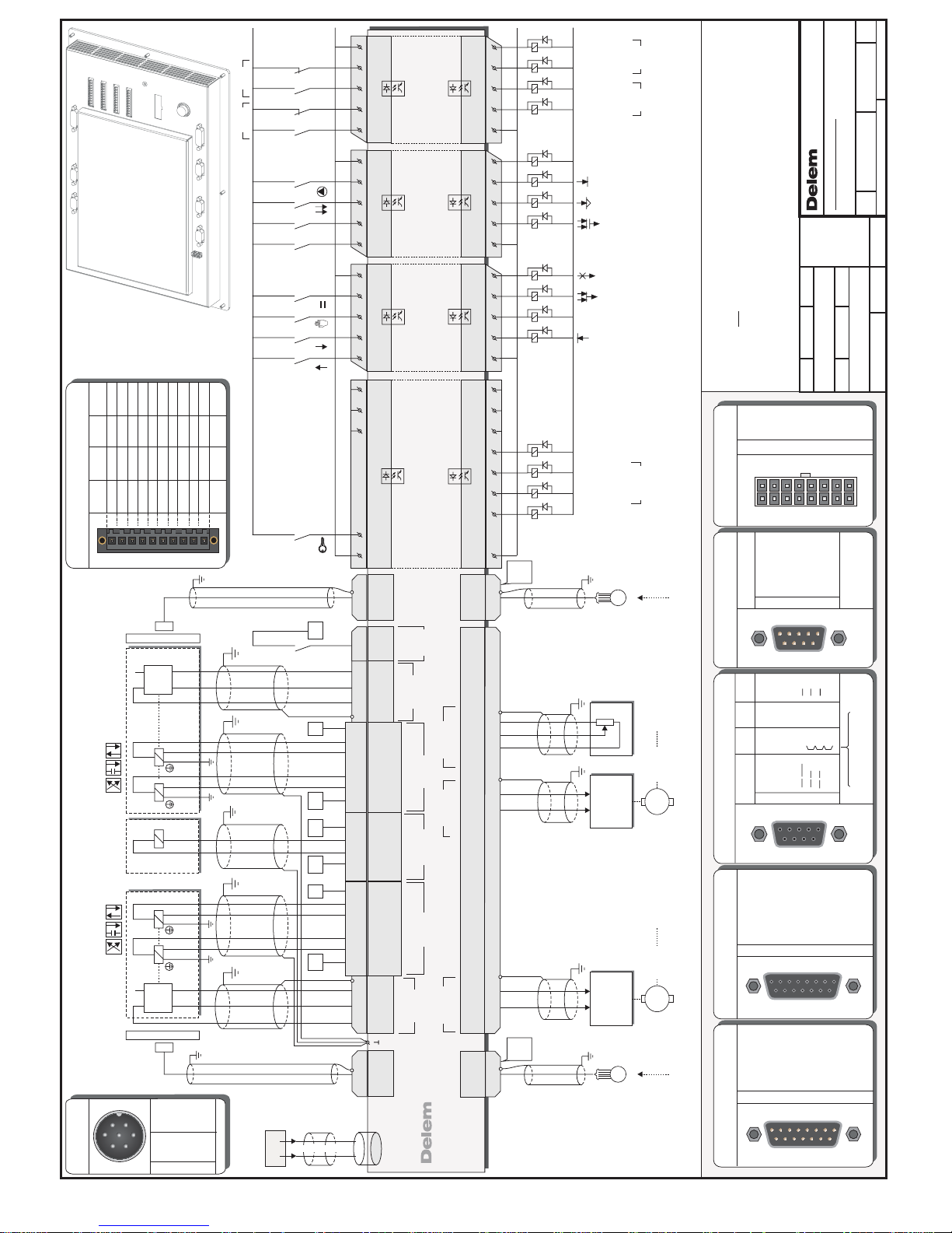
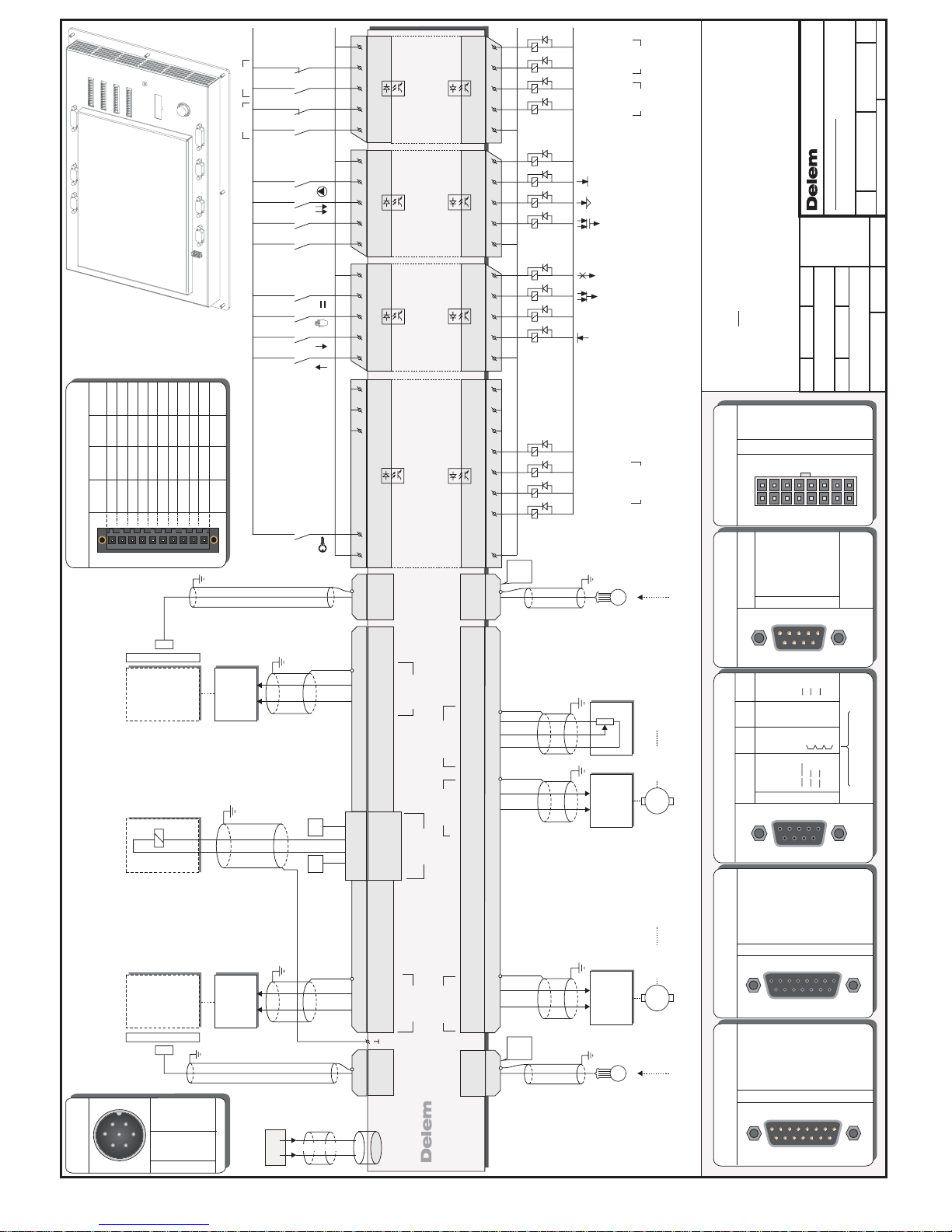
run through connector Analog B. An example of the required wiring is given in diagram 8061-
102.
Optional: Y-VA
The connector is used for direct control of the proportional valves.
An example of the required wiring for direct valve control is given in diagram 8061-101. This
schematic also includes a pin description of the connector. The position feedback from the
valve transducers (LVDT) is connected to connector Analog B.
See section 3.4 for more information about connector Analog B.
Analogue outputs:
Prop. Valve: Y1/Y2 4 x 3A max.
Pressure valve: P 1.5 A max.
Analogue inputs:
24V Power Supply 18-30V DC
ripple +/- 2V max.
max. 13A
Shielding of cables should be connected to the available M3 ground plug beside the
connector.
Page 12
Delem
V0614, 1.12
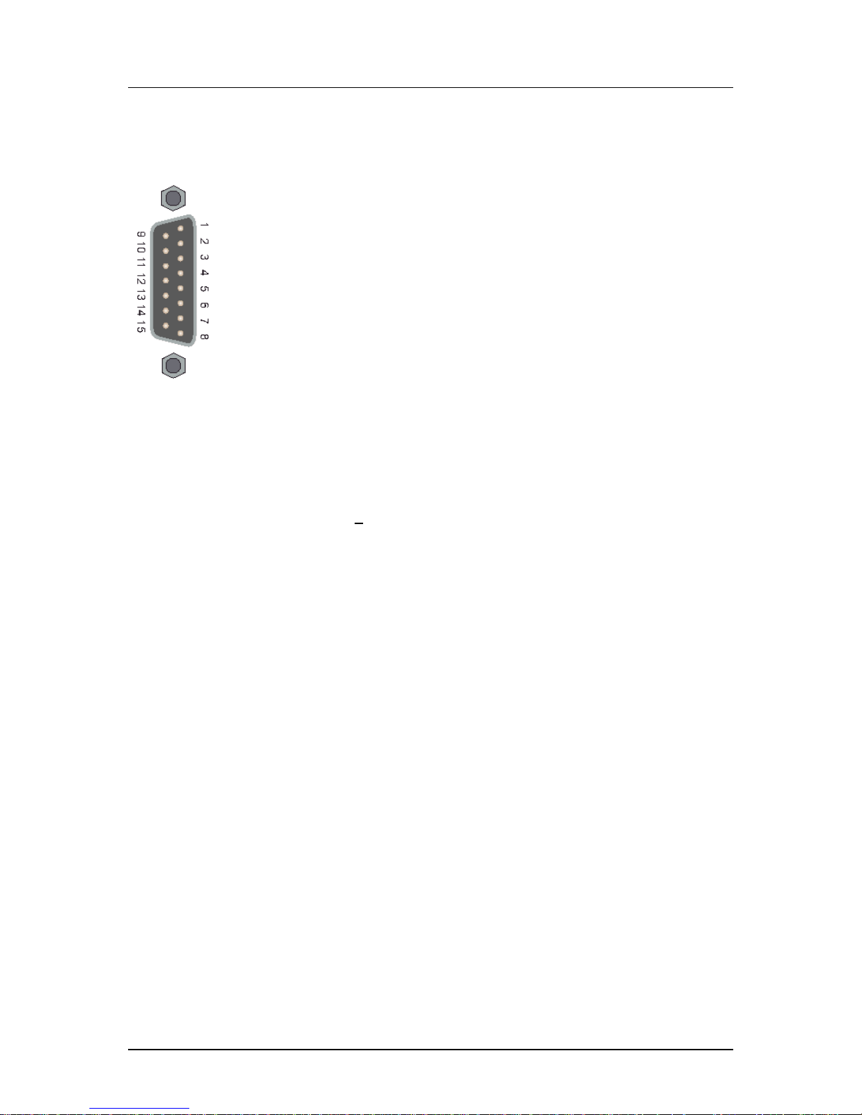
3.5. Analog A
Connector Analog A provides several analog signals, two analog
outputs and four analog inputs.
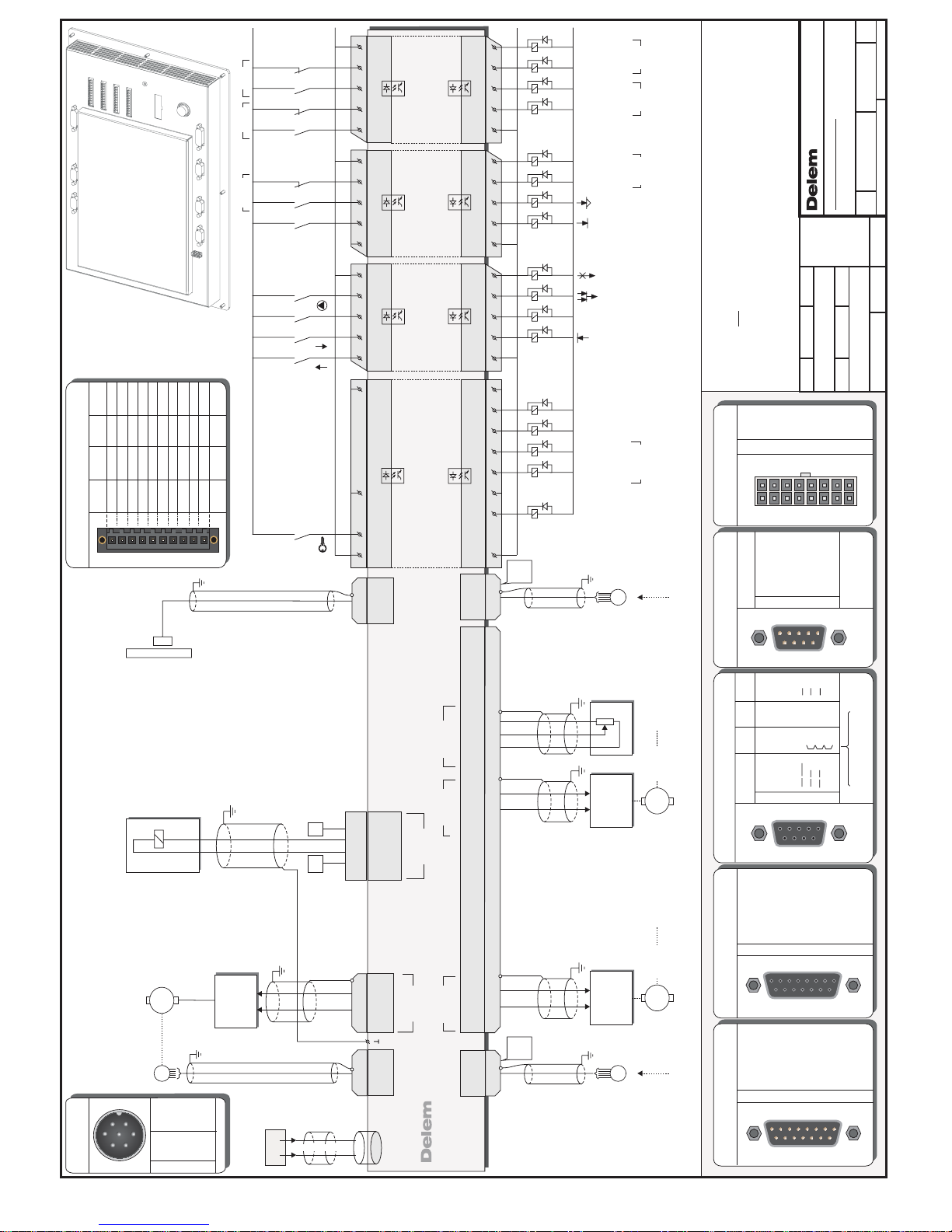
See schematic 8061-101 for connection details.
Specifications for Analog I/O
Analogue inputs (4x)
0-10V, input impedance 44 kΩ
Reference voltage (2x)
10V + 2%
Analogue outputs (2x)
+/- 10V
10mA max.
maximum load 1 kΩ
Page 13
Delem
V0614, 1.13
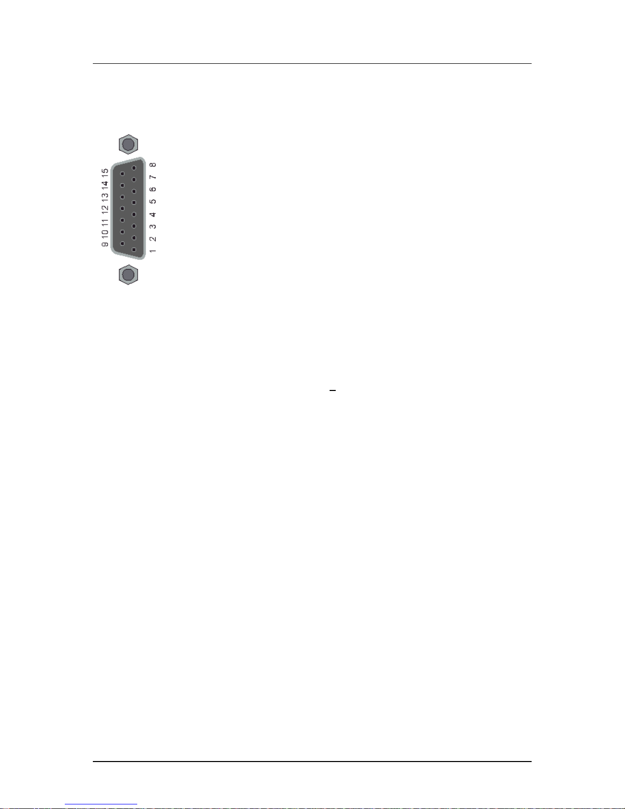
3.6. Analog B
Connector Analog B provides several analog signals, two analog
outputs and two analog inputs. It also includes power supply for
possible valve position transducers (LVDT).
See schematic 8061-101 for connection details.
Specifications for Analog I/O
Analogue inputs (2x)
0-12V / -10V ... +10V,
input impedance 44 kΩ
Supply voltage 24V + 2%
Analogue outputs (2x)
+/- 10V
10mA max.
maximum load 1 kΩ
Analogue output (1x)
0 - 10V (ext. pressure amplifier)
Power outputs (6x)
2x -12V
2x +12V
2x 24V
100 mA max. for each transducer
Notes:
• Used power supply depends on transducer specifications (+/-12V or 24V).
3.7. Digital I/O
12 inputs, 12 outputs, 8 programmable I/O.
Page 14
Delem
V0614, 1.14
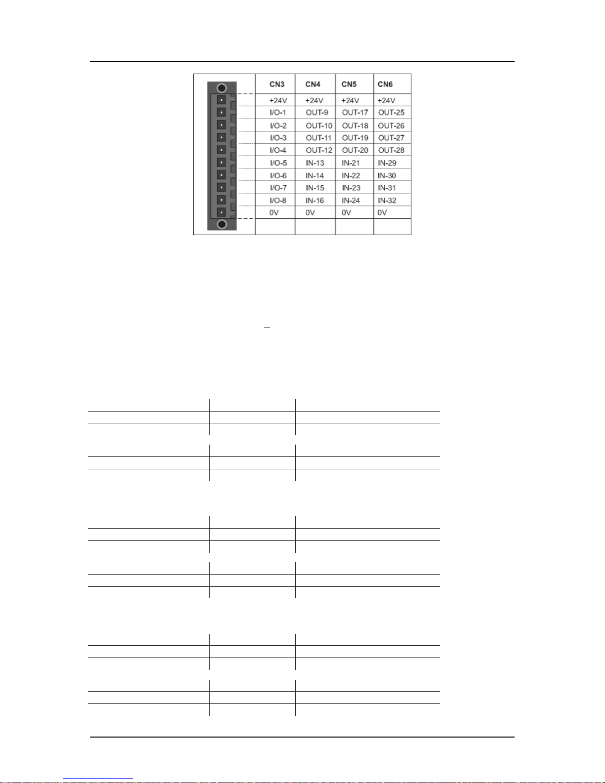
Figure 3.b
See schematic 8061-101 for connection details.
The use of I/O pins depends on the application and machine settings. For the purpose of all
assigned I/O signals we refer to the Delem machine parameter manual.
I/O power supply: 24 V DC + 20%
10A m ax.
CN3: Pins 1 - 8
Programmable Digital In-/Outputs (8x):
Digital Output
Voltage
Current
ON state
20-28 V DC
0.5 A max.
OFF state
-
0.1 mA max. (leakage current)
Digital Input
Voltage
Current
ON state
9-28 V DC
20mA max.
OFF state
0-4 V DC
1 mA max.
CN4: Pins 9 - 16
Digital Outputs (4x)
Voltage
Current
ON state
20-28 V DC
0.5 A max.
OFF state
-
0.1 mA max. (leakage current)
Digital Inputs (4x)
Voltage
Current
ON state
9-28 V DC
20mA max.
OFF state
0 - 4 V DC
1 mA max.
CN5: Pins 17 - 24
Digital Outputs (4x)
Voltage
Current
ON state
20-28 V DC
0.5 A max.
OFF state
-
0.1 mA max. (leakage curr ent)
Digital Inputs (4x)
Voltage
Current
ON state
9-28 V DC
20mA max.
OFF state
0 - 4 V DC
1 mA max.
Page 15

Delem
V0614, 1.15
CN6: Pins 25 - 32
Digital Outputs (4x)
Voltage
Current
ON state
20-28 V DC
0.5 A max.
OFF state
-
0.1 mA max. (leakage current)
Digital Inputs (4x)
Voltage
Current
ON state
9-28 V DC
20mA max.
OFF state
0 - 4 V DC
1 mA max.
Notes:
• The sum of all output currents should not exceed 10A.
• All digital outputs are short-circuit proof.
• To guarantee a defined state during power on or off, the load of the outputs should
comply with IEC 61131.
Page 16
Delem
V0614, 1.16
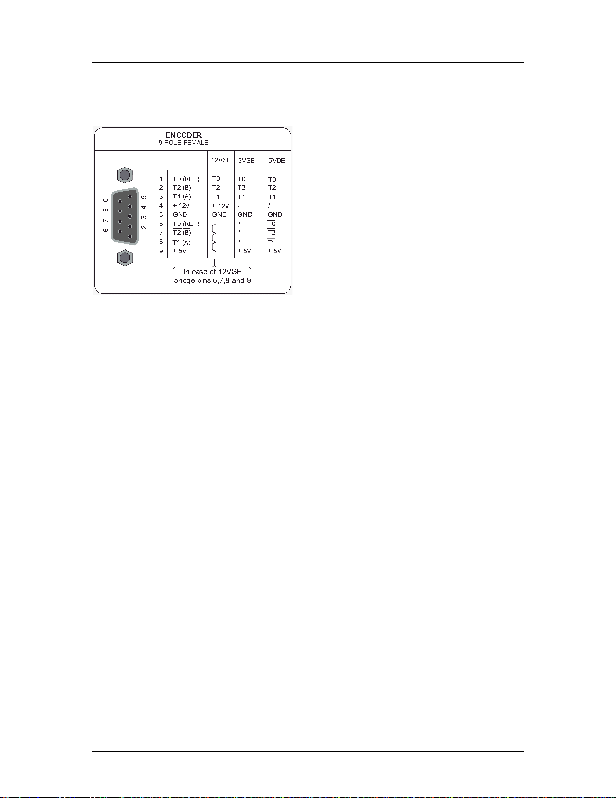
3.8. Encoders
9-pole SUBD female encoder interface
5V DC/250 mA or 12V DC/200 mA
12 V or 5 V single ended or 5 V
differential
Max. count frequency 1 MHz
See schematic 8061-101 for connection details.
Notes:
• In case of 12VSE encoder, connect pins 6, 7, 8 and 9 with each other.
Page 17
Delem
V0614, 1.17
4. Spare parts
4.1. Introduction
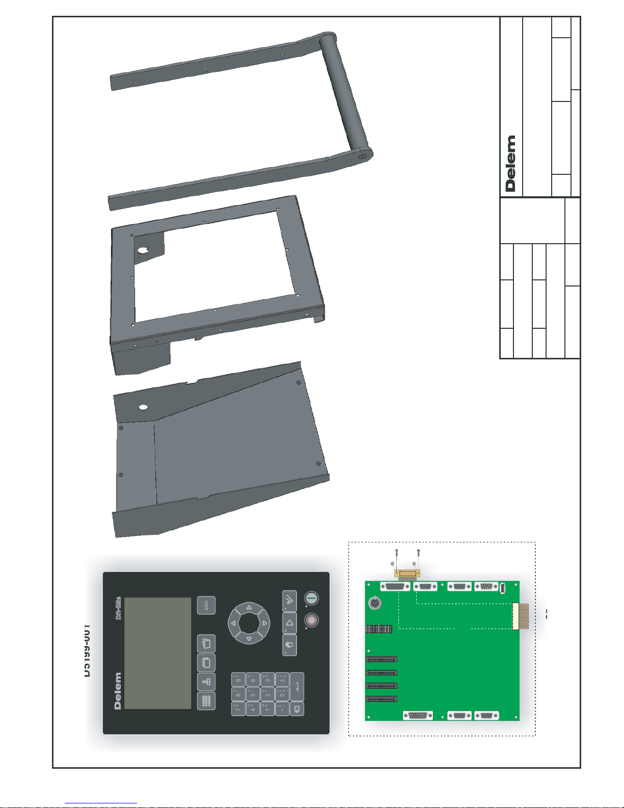
The following table gives an overview of the available spare parts for the DA-52s controls.
The next chapter contains an exploded view of a DA-52s control, in which the same spare
part numbers are used.
Number
Description
D5199-001
DA-52s frontpanel
D5180-003
Mainboard
D6194-002
Frame
D6195-002
Cover
D5195-003
Grip
Page 18

Delem
V0614, 1.18
5. Schematics
The following pages show several schematics about the DA-52s control.
Page 19
Note Redrawn
Redrawn
Date
Date
Date
Description
Description
Note
DrawnMeasures in mm,unless
otherwise specified
No unauthorized copying allowed
Format Number Issue
Scale
Luchthavenweg 42, 5657 EB
Eindhoven, The NETHERLANDS
A3
HNF 20-06-2012
DA-52s
Spare parts
HNF 27-11-2012B
FRU Partnumbers changed / added
8079-903
B
D5199-001
D6194-002
Frame
D5195-003
Grip
D6195-002
Cover
D5180-003 Mainboard DA-52s
18
3
ar
d
5
2s
Mainboard
+
Cable-LCD
999-9-9-9-9-
9-
FRONT - 52s
Page 20
Note Redrawn
Redrawn
Date
Date
Date
Description
Description
Note
DrawnMeasures in mm,unless
otherwise specified
No unauthorized copying allowed
Format Number Issue
Scale
Luchthavenweg 42, 5657 EB
Eindhoven, The NETHERLANDS
Mounting dimensions
A3
HNF 20-06-2012
ANALOG B
1 2 3 4 5 6 7 8
9 10 11 12 13 14 15
ANALOG A
1 2 3 4 5 6 7 8
9 10 11 12 13 14 15
1 2 3 4 5
6 7 8 9
COM
1 2 3 4 5
6 7 8 9
ENCODER Y2
VALVE
1 2 3 4 5 6 7 8
POWER
1
2
3
4
5
6
7
1 2 3 4 5
6 7 8 9
ENCODER AUX. 1
1 2 3 4 5
6 7 8 9
ENCODER AUX. 2
1 2 3 4 5
6 7 8 9
ENCODER Y1
I/O
T
USB
9 10 11 12 13 14 15 16
I/O1
I/O2
I/O3
I/O4
I/O5
I/O6
I/O7
I/O8
+24V
0V
+24V +24V
0V
+24V
0V 0V
OUT9
OUT10
OUT11
OUT12
IN13
IN14
IN15
IN16
OUT17
OUT18
OUT19
OUT20
IN21
IN22
IN23
IN24
OUT25
OUT26
OUT27
OUT28
IN29
IN30
IN31
IN32
INPUTS / OUTPUTS
CN3 CN4 CN5 CN6
CN1
CN2
CN7
CN8
CN9
CN10
CN12
CN14
CN16
CN20
5885-011/-
Eindhoven
POWER 24V DC
Type:
DA-52s
Serial number:
Made in the Netherlands8079-00N
NNNNN
8079-901
DA-52s
DA-52s
A
34.0 mm
(8 x) M4
9.0 mm
TOP
BACKSIDE
FRONT
M4
M4
(Max. 4.0 mm)
FRONTVIEW
TOP
CUT OUT DIMENSIONS DIMENSIONS
100.0 mm
48.0 mm
M4
8 x O 4.2 mm
BOTTOM
(4.5 mm)
(4.5 mm)
209 mm
297 mm
200 mm
288 mm
104.5 mm
148.5 mm
Page 21
Page 22
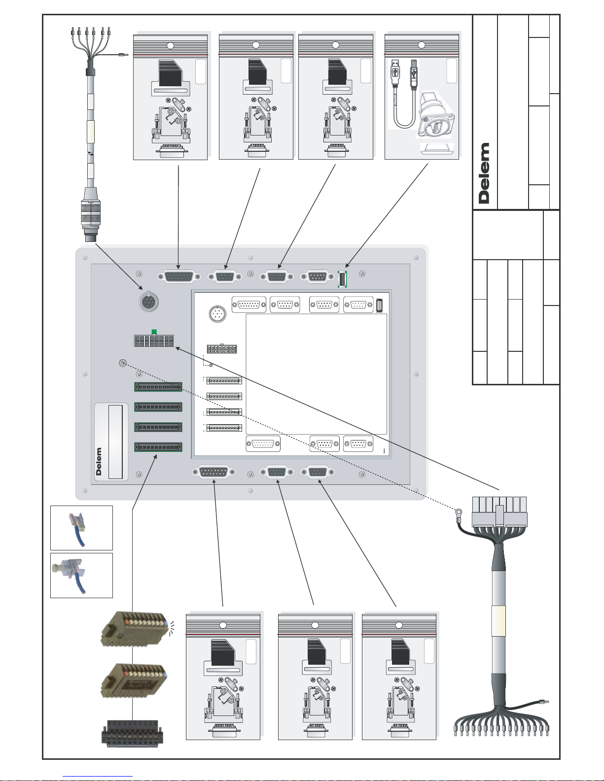
No unauthorized copying allowed
Format Number Issue
Note Redrawn
Redrawn
Date
Date
Date
Description
Description
Note
DrawnMeasures in mm,unless
otherwise specified
Scale
Luchthavenweg 42, 5657 EB
Eindhoven, the NETHERLANDS
A3
HNF
20-06-2012
DA-52s cables & connectors
8079-902 A
ANALOG B
1 2 3 4 5 6 7 8
9 10 11 12 13 14 15
ANALOG A
1 2 3 4 5 6 7 8
9 10 11 12 13 14 15
1 2 3 4 5
6 7 8 9
COM
1 2 3 4 5
6 7 8 9
ENCODER Y2
VALVE
1 2 3 4 5 6 7 8
POWER
1
2
3
4
5
6
7
1 2 3 4 5
6 7 8 9
ENCODER AUX. 1
1 2 3 4 5
6 7 8 9
ENCODER AUX. 2
1 2 3 4 5
6 7 8 9
ENCODER Y1
I/O
T
USB
9 10 11 12 13 14 15 16
I/O1
I/O2
I/O3
I/O4
I/O5
I/O6
I/O7
I/O8
+24V
0V
+24V +24V
0V
+24V
0V 0V
OUT9
OUT10
OUT11
OUT12
IN13
IN14
IN15
IN16
OUT17
OUT18
OUT19
OUT20
IN21
IN22
IN23
IN24
OUT25
OUT26
OUT27
OUT28
IN29
IN30
IN31
IN32
INPUTS / OUTPUTS
CN3 CN4 CN5 CN6
CN1
CN2
CN7
CN8
CN9
CN10
CN12
CN14
CN16
CN20
5885-011/-
Eindhoven
POWER 24V DC
Type:
DA-52s
Serial number:
Made in the Netherlands8079-00N
NNNNN
ANALOG B
ENCODER Y1
ENCODER Y2
ANALOG A
5060-005
15p.SubD Female
DC-SUBD-15-F-CP
5060-004
15p.SubD Male
DC-SUBD-15-M-CP
DC-161586 DC-177988 DC-178909
Clamping-yoke
connection
(screw)
Spring connection Spring connection
+ Led indication
1 x Power LED
8 x I/O LED
DC-SUBD-9-M-CP
5060-001
9p.SubD Male
DC-SUBD-9-M-CP
5060-001
9p.SubD Male
DC-SUBD-9-M-CP
5060-001
9p.SubD Male
DC-SUBD-9-M-CP
5060-001
9p.SubD Male
ENCODER AUX 1
ENCODER AUX 2
I/O, INPUTS & OUTPUTS
DK-1079-003 4.0 m
Full version:
or
Pressure control version only:
DK-1079-007
1079-003/-
4.0 m
DK-1079-004 6.0 m
DK-1079-005 9.0 m
DK24-N40 4.0 m
DK24-N50 5.0 m
DK24-N100 10.0 m
1128-00N/n
POWER 24VDC
Clamping-yoke
connection
(screw)
Spring
connection
DK-1079-008 6.0 m
DK-1079-009 9.0 m
EXTERNAL USB
DC-USB
5181-001
USB-A/B-cable 0.65 M
Page 23
No unauthorized copying allowed
Format Number Issue
Note Redrawn
Redrawn
Date
Date
Date
Description
Description
Note
DrawnMeasures in mm,unless
otherwise specified
Scale
Luchthavenweg 42, 5657 EB
Eindhoven, the NETHERLANDS
A3
Page 1 /1
02-02-2007
24V
0V
POWER
0V
24V
HNF
Example connections:
Note 1 : Leave unconnected pins open.
Note 2 : 24V relais supply must be separated from 24V supply
ANALOG A
0V
I/O
24V
I/O
0V
I/O
24V
I/O
See drawing 8061-901
for mounting dimensions
Delem 1128-00N
ANALOG A
15 POLE MALE
1
OUTAN1 -10V...+10V
IN1B
IN1B 0V
OUTAN1 0V
N.C.
OUTAN2 -10V...+10V
REF1 10V
IN1A
IN1A 0V
2345678
9
IN2A
IN2A 0V
IN2B
IN2B 0V
OUTAN2 0V
REF2 10V
1011121314
15
12345678
9101112131415
CN7
1
Request to Send
Received Data
Clear to Send
Not connected
Transmitted Data
Signal Ground
2345678
9
12345
6789
SERIAL
9 POLE MALE
Not connected
Not connected
Not connected
CN16
12VSE
5VSE 5VDE
1
T0 (REF)
T0 (REF)
T2 (B)
T2 (B)
T1 (A)
+5V
+5V
In case of 12VSE
bridge pins 6,7,8 and 9
+5V
T1 (A)
+ 12V
+ 12V
GND
GND GND GND
T0T0T2T2T1
T1
T2
T1
T2T1/
///
/T0T0
2345678
9
12345
6789
ENCODER
9 POLE FEMALE
12VSE
5VSE 5VDE
1
T0 (REF)
T0 (REF)
T2 (B)
T2 (B)
T1 (A)
+5V
+5V
In case of 12VSE
bridge pins 6,7,8 and 9
+5V
T1 (A)
+ 12V
+ 12V
GND
GND GND GND
T0T0T2T2T1
T1
T2
T1
T2T1/
///
/T0T0
2345678
9
12345
6789
ENCODER
9 POLE FEMALE
CN10,14,9,12
INPUTS / OUTPUTS
10 POLE MALE
+24V
I/O-1
I/O-2
I/O-3
I/O-4
I/O-5
I/O-6
I/O-7
I/O-8
0V
+24V
OUT-9
OUT-10
OUT-11
OUT-12
IN-13
IN-14
IN-15
IN-16
0V
+24V
OUT-17
OUT-18
OUT-19
OUT-20
IN-21
IN-22
IN-23
IN-24
0V
+24V
OUT-25
OUT-26
OUT-27
OUT-28
IN-29
IN-30
IN-31
IN-32
0V
CN3 CN4 CN5 CN6
8061-0NN
DA-52
2
5
2
5
galvanic insulation
OUTPUTS
INPUTS
galvanic insulation
0V
COM
16151413
24V
1211109
COM
CN4
galvanic insulation
OUTPUTS
INPUTS
galvanic insulation
0V
COM
24
23
2221
24V
20191817
COM
CN5
galvanic insulation
OUTPUTS
INPUTS
galvanic insulation
0V
COM
32
31
3029
24V
28272625
COM
CN6
PIN 1-8 programmable
galvanic insulation
galvanic insulation
0V
COM
5432
24V
4321
COM
5
1
768
876
CN3
INPUTS
OUTPUTS
CN2
CN7
8061-101
VALVE
16 POLE MALE
1
Y1 0V
Y2 B-
P0V
Y1 A-
P-
Y1 24V
Y1 B-
Y2 0V
Y2 A-
2345678
9
Y2 24V
Y2 A+
Y2 B+
P 24V
Y1 A+
Y1 B+
1011121314
15
P+
16
910 111213141516
12345678
CN1
POWER
CN2 7 POLE MALE
N.C.
N.C.
SHIELD
24V
N.C.
N.C.
0V
34567
1
2
-
-
Ground
Power +
--Power -
1
2
3
4
5
6
7
ANALOG B
15 POLE FEMALE
1
Y1 -12V
Y1 +/-10V
P0V
Y1 +12V
P 0-10V
Y2 -12V
Y1 24V Max.100mA
Y1 LVDT
Y1 0V
2345678
9
Y2 LVDT
Y2 0V
Y2 +/-10V
Y2 +12V
Y2 24V Max.100mA
1011121314
15
12345678
9101112131415
CN8
Valve Enable
13-08-2007HNFA
A
CN10CN14CN16
CN20
CN9CN12
Encoder
AUX.2
Encoder
AUX.1
Analog A
COM 1
Encoder Y2
Encoder Y1
Analog B
USB 1
CN1
Valve
CN2
Power
Delem 8061-00N
CN3
CN4
CN5
CN6
Inputs/outputs
CN7
CN8
Function output F4
Function output F1
KEY LOCK
Potentiometer
10K
10V
0-10V
0V
11 1 2
13
IN2A
IN2A
0V
REF2
10V
A<
A>
Crowning
Crowning
Crowning.M.
Crowning
OUTAN2
-10V..+10V
OUTAN2
0V
+/-10V
0V
0V+/-10V
Amplifier
10
9
Servo
Axis 2
M
Axis 2
Axis 2
RSD
START
Axis 2
Axis 2
IN POSITION
OK
Feedback
Servo 2,
*See connection diagram: for details " OK & START"9087-102
*
*
Ref.9087-102 details "OK & START" added
Feedback
OUTAN1
-10V..+10V
OUTAN1
0V
+/-10V
0V
0V+/-10V
Amplifier
2
1
Servo
Axis 1
M
Axis 1
Axis 1
RSD
START
IN POSITION
OK
Axis 1
Axis 1
Servo 1,
*See connection diagram: for details " OK & START"9087-102
*
*
Ref.9087-102 details "OK & START" added
9P.
SUBD
Male
1 t/m 9
E
CN12
Feedback
Axis 2
Encoder
ENCODER
Auxiliary 2
1 t/m 9
E
ENCODER
Auxiliary 1
Feedback
Axis 1
CN9
Encoder
9P.
SUBD
Male
13514612 4
131211
13514612 4
Valve Y2
2
1
2
1
BA
0V24V
Valve Y2
VALV E Y 2
24V
0V
LVDTY2
ANALOG B
LVDTY2
24V A+A- B+B- 0V
Linear
Scale Y2
1 t/m 9
Note3:Do place a diode across valves.not
Max. 100 mA
LVDT
Y2
1
23
4
Y2,
CN1
CN14CN8
ENCODER
Y2
0VLVDTY124V
10211391
354
0V
Valve Y1
LVDT
Y1
2
1
2
1
BA
24V
ANALOG B
Valve Y1
VALV E Y 1
LVDTY1
A+A- B+B-
24V
0V
Linear
Scale Y1
1 t/m 9
ENCODER
Y1
Note3:Do place a diode across valves.not
Max. 100 mA
1
23
4
Y1,
CN1
CN10 CN8
15
VALV E
ENABLE
VALV E
ENABLE
24V
Valve
Enable
CN8
PIN15 CN8 ANALOG B = "ValveEnable"
81615 7
24V
System
Pressure
0V
System
Pressure
P+
P-P24V
P0V
OPENING
PRESSING
MANUAL
PARALLEL
T (Tandem)
C (step
Change)
PUMP
ER
(End of Relaxtion)
UDP
(Upper Dead Point)
CNC START
MUTE
CLAMP
2nd MUTE
CNC READY
LDP
(Lower Dead Point)
VALV E
Note3:Do place a diode across valves.not
FAST
CLOSING
P,
CN1
Page 24
No unauthorized copying allowed
Format Number Issue
Note Redrawn
Redrawn
Date
Date
Date
Description
Description
Note
DrawnMeasures in mm,unless
otherwise specified
Scale
Luchthavenweg 42, 5657 EB
Eindhoven, the NETHERLANDS
A3
Page 1 /1
02-02-2007
24V
0V
POWER
0V
24V
HNF
Example connections:
Note 1 : Leave unconnected pins open.
Note 2 : 24V relais supply must be separated from 24V supply
ANALOG A
0V
I/O
24V
I/O
0V
I/O
24V
I/O
See drawing 8061-901
for mounting dimensions
Delem 1128-00N
ANALOG A
15 POLE MALE
1
OUTAN1 -10V...+10V
IN1B
IN1B 0V
OUTAN1 0V
N.C.
OUTAN2 -10V...+10V
REF1 10V
IN1A
IN1A 0V
2345678
9
IN2A
IN2A 0V
IN2B
IN2B 0V
OUTAN2 0V
REF2 10V
1011121314
15
12345678
9101112131415
CN7
1
Request to Send
Received Data
Clear to Send
Not connected
Transmitted Data
Signal Ground
2345678
9
12345
6789
SERIAL
9 POLE MALE
Not connected
Not connected
Not connected
CN16
12VSE
5VSE 5VDE
1
T0 (REF)
T0 (REF)
T2 (B)
T2 (B)
T1 (A)
+5V
+5V
In case of 12VSE
bridge pins 6,7,8 and 9
+5V
T1 (A)
+ 12V
+ 12V
GND
GND GND GND
T0T0T2T2T1
T1
T2
T1
T2T1/
///
/T0T0
2345678
9
12345
6789
ENCODER
9 POLE FEMALE
12VSE
5VSE 5VDE
1
T0 (REF)
T0 (REF)
T2 (B)
T2 (B)
T1 (A)
+5V
+5V
In case of 12VSE
bridge pins 6,7,8 and 9
+5V
T1 (A)
+ 12V
+ 12V
GND
GND GND GND
T0T0T2T2T1
T1
T2
T1
T2T1/
///
/T0T0
2345678
9
12345
6789
ENCODER
9 POLE FEMALE
CN10,14,9,12
INPUTS / OUTPUTS
10 POLE MALE
+24V
I/O-1
I/O-2
I/O-3
I/O-4
I/O-5
I/O-6
I/O-7
I/O-8
0V
+24V
OUT-9
OUT-10
OUT-11
OUT-12
IN-13
IN-14
IN-15
IN-16
0V
+24V
OUT-17
OUT-18
OUT-19
OUT-20
IN-21
IN-22
IN-23
IN-24
0V
+24V
OUT-25
OUT-26
OUT-27
OUT-28
IN-29
IN-30
IN-31
IN-32
0V
CN3 CN4 CN5 CN6
8061-0NN
DA-52
2
5
2
5
galvanic insulation
OUTPUTS
INPUTS
galvanic insulation
0V
COM
16151413
24V
1211109
COM
CN4
galvanic insulation
OUTPUTS
INPUTS
galvanic insulation
0V
COM
24
23
2221
24V
20191817
COM
CN5
galvanic insulation
OUTPUTS
INPUTS
galvanic insulation
0V
COM
32
31
3029
24V
28272625
COM
CN6
PIN 1-8 programmable
galvanic insulation
galvanic insulation
0V
COM
5432
24V
4321
COM
5
1
768
876
CN3
INPUTS
OUTPUTS
CN2
CN7
8061-102
VALVE
16 POLE MALE
1
Y1 0V
Y2 B-
P0V
Y1 A-
P-
Y1 24V
Y1 B-
Y2 0V
Y2 A-
2345678
9
Y2 24V
Y2 A+
Y2 B+
P 24V
Y1 A+
Y1 B+
1011121314
15
P+
16
910 111213141516
12345678
CN1
POWER
CN2 7 POLE MALE
N.C.
N.C.
SHIELD
24V
N.C.
N.C.
0V
34567
1
2
-
-
Ground
Power +
--Power -
1
2
3
4
5
6
7
ANALOG B
15 POLE FEMALE
1
Y1 -12V
Y1 +/-10V
P0V
Y1 +12V
P 0-10V
Y2 -12V
Y1 24V Max.100mA
Y1 LVDT
Y1 0V
2345678
9
Y2 LVDT
Y2 0V
Y2 +/-10V
Y2 +12V
Y2 24V Max.100mA
1011121314
15
12345678
9101112131415
CN8
Valve Enable
13-08-2007HNFA
A
CN10CN14CN16
CN20
CN9CN12
Encoder
AUX.2
Encoder
AUX.1
Analog A
COM 1
Encoder Y2
Encoder Y1
Analog B
USB 1
CN1
Valve
CN2
Power
Delem 8061-00N
CN3
CN4
CN5
CN6
Inputs/outputs
CN7
CN8
Function output F4
Function output F1
KEY LOCK
Potentiometer
10K
10V
0-10V
0V
11 1 2
13
IN2A
IN2A
0V
REF2
10V
A<
A>
Crowning
Crowning
Crowning.M.
Crowning
OUTAN2
-10V..+10V
OUTAN2
0V
+/-10V
0V
0V+/-10V
Amplifier
10
9
Servo
Axis 2
M
Axis 2
Axis 2
RSD
START
Axis 2
Axis 2
IN POSITION
OK
Feedback
Servo 2,
*See connection diagram: for details " OK & START"9087-102
*
*
Ref.9087-102 details "OK & START" added
Feedback
OUTAN1
-10V..+10V
OUTAN1
0V
+/-10V
0V
0V+/-10V
Amplifier
2
1
Servo
Axis 1
M
Axis 1
Axis 1
RSD
START
IN POSITION
OK
Axis 1
Axis 1
Servo 1,
*See connection diagram: for details " OK & START"9087-102
*
*
Ref.9087-102 details "OK & START" added
9P.
SUBD
Male
1 t/m 9
E
CN12
Feedback
Axis 2
Encoder
ENCODER
Auxiliary 2
1 t/m 9
E
ENCODER
Auxiliary 1
Feedback
Axis 1
CN9
Encoder
9P.
SUBD
Male
+/-10V
0V
0V +/-10V
Valve Y2
Amplifier
Valve Y2
1413
Y2 +/-10V
0V
ANALOG B
Linear
Scale Y2
1 t/m 9
Valve Y2
Y2-ext,
Note 4 : At the UDP the valve amplifiers should be disabled.
The fast closing command should only be activated when both
high retaining valves are opened.
The valve amplifiers should be enabled when the fast closing
command is activated.
CN14CN8
ENCODER
Y2
+/-10V
0V
0V +/-10V
Valve Y1
Amplifier
Valve Y1
65
ANALOG B
Y1 +/-10V
0V
Linear
Scale Y1
1 t/m 9
Valve Y1
Note 4 : At the UDP the valve amplifiers should be disabled.
The fast closing command should only be activated when both
high retaining valves are opened.
The valve amplifiers should be enabled when the fast closing
command is activated.
Y1-ext,
CN10 CN8
ENCODER
Y1
81615 7
24V
System
Pressure
0V
System
Pressure
P+
P-P24V
P0V
OPENING
PRESSING
MANUAL
PARALLEL
T (Tandem)
C (step
Change)
PUMP
ER
(End of Relaxtion)
UDP
(Upper Dead Point)
CNC START
MUTE
CLAMP
2nd MUTE
CNC READY
LDP
(Lower Dead Point)
VALV E
Note3:Do place a diode across valves.not
FAST
CLOSING
P,
CN1
Page 25
No unauthorized copying allowed
Format Number Issue
Note Redrawn
Redrawn
Date
Date
Date
Description
Description
Note
DrawnMeasures in mm,unless
otherwise specified
Scale
Luchthavenweg 42, 5657 EB
Eindhoven, the NETHERLANDS
A3
Page 1 /1
02-02-2007
24V
0V
POWER
0V
24V
HNF
Example connections:
Note 1 : Leave unconnected pins open.
Note 2 : 24V relais supply must be separated from 24V supply
ANALOG A
0V
I/O
24V
I/O
0V
I/O
24V
I/O
See drawing 8061-901
for mounting dimensions
Delem 1128-00N
ANALOG A
15 POLE MALE
1
OUTAN1 -10V...+10V
IN1B
IN1B 0V
OUTAN1 0V
N.C.
OUTAN2 -10V...+10V
REF1 10V
IN1A
IN1A 0V
2345678
9
IN2A
IN2A 0V
IN2B
IN2B 0V
OUTAN2 0V
REF2 10V
1011121314
15
12345678
9101112131415
CN7
1
Request to Send
Received Data
Clear to Send
Not connected
Transmitted Data
Signal Ground
2345678
9
12345
6789
SERIAL
9 POLE MALE
Not connected
Not connected
Not connected
CN16
12VSE
5VSE 5VDE
1
T0 (REF)
T0 (REF)
T2 (B)
T2 (B)
T1 (A)
+5V
+5V
In case of 12VSE
bridge pins 6,7,8 and 9
+5V
T1 (A)
+ 12V
+ 12V
GND
GND GND GND
T0T0T2T2T1
T1
T2
T1
T2T1/
///
/T0T0
2345678
9
12345
6789
ENCODER
9 POLE FEMALE
12VSE
5VSE 5VDE
1
T0 (REF)
T0 (REF)
T2 (B)
T2 (B)
T1 (A)
+5V
+5V
In case of 12VSE
bridge pins 6,7,8 and 9
+5V
T1 (A)
+ 12V
+ 12V
GND
GND GND GND
T0T0T2T2T1
T1
T2
T1
T2T1/
///
/T0T0
2345678
9
12345
6789
ENCODER
9 POLE FEMALE
CN10,14,9,12
INPUTS / OUTPUTS
10 POLE MALE
+24V
I/O-1
I/O-2
I/O-3
I/O-4
I/O-5
I/O-6
I/O-7
I/O-8
0V
+24V
OUT-9
OUT-10
OUT-11
OUT-12
IN-13
IN-14
IN-15
IN-16
0V
+24V
OUT-17
OUT-18
OUT-19
OUT-20
IN-21
IN-22
IN-23
IN-24
0V
+24V
OUT-25
OUT-26
OUT-27
OUT-28
IN-29
IN-30
IN-31
IN-32
0V
CN3 CN4 CN5 CN6
8061-0NN
DA-52
2
5
2
5
galvanic insulation
OUTPUTS
INPUTS
galvanic insulation
0V
COM
16151413
24V
1211109
COM
CN4
galvanic insulation
OUTPUTS
INPUTS
galvanic insulation
0V
COM
24
23
2221
24V
20191817
COM
CN5
galvanic insulation
OUTPUTS
INPUTS
galvanic insulation
0V
COM
32
31
3029
24V
28272625
COM
CN6
PIN 1-8 programmable
galvanic insulation
galvanic insulation
0V
COM
5432
24V
4321
COM
5
1
768
876
CN3
INPUTS
OUTPUTS
CN2
CN7
8061-103
VALVE
16 POLE MALE
1
Y1 0V
Y2 B-
P0V
Y1 A-
P-
Y1 24V
Y1 B-
Y2 0V
Y2 A-
2345678
9
Y2 24V
Y2 A+
Y2 B+
P 24V
Y1 A+
Y1 B+
1011121314
15
P+
16
910 111213141516
12345678
CN1
POWER
CN2 7 POLE MALE
N.C.
N.C.
SHIELD
24V
N.C.
N.C.
0V
34567
1
2
-
-
Ground
Power +
--Power -
1
2
3
4
5
6
7
ANALOG B
15 POLE FEMALE
1
Y1 -12V
Y1 +/-10V
P0V
Y1 +12V
P 0-10V
Y2 -12V
Y1 24V Max.100mA
Y1 LVDT
Y1 0V
2345678
9
Y2 LVDT
Y2 0V
Y2 +/-10V
Y2 +12V
Y2 24V Max.100mA
1011121314
15
12345678
9101112131415
CN8
Valve Enable
13-08-2007HNFA
A
CN10CN14CN16
CN20
CN9CN12
Encoder
AUX.2
Encoder
AUX.1
Analog A
COM 1
Encoder Y2
Encoder Y1
Analog B
USB 1
CN1
Valve
CN2
Power
Delem 8061-00N
CN3
CN4
CN5
CN6
Inputs/outputs
CN7
CN8
Function output F1
KEY LOCK
Potentiometer
10K
10V
0-10V
0V
11 1 2
13
IN2A
IN2A
0V
REF2
10V
A<
A>
Crowning
Crowning
Crowning.M.
Crowning
OUTAN2
-10V..+10V
OUTAN2
0V
+/-10V
0V
0V+/-10V
Amplifier
10
9
Servo
Axis 2
M
Axis 2
Axis 2
RSD
START
Axis 2
Axis 2
IN POSITION
OK
Feedback
Servo 2,
*See connection diagram: for details " OK & START"9087-102
*
*
Ref.9087-102 details "OK & START" added
Feedback
OUTAN1
-10V..+10V
OUTAN1
0V
+/-10V
0V
0V+/-10V
Amplifier
2
1
Servo
Axis 1
M
Axis 1
Axis 1
RSD
START
IN POSITION
OK
Axis 1
Axis 1
Servo 1,
*See connection diagram: for details " OK & START"9087-102
*
*
Ref.9087-102 details "OK & START" added
9P.
SUBD
Male
1 t/m 9
E
CN12
Feedback
Axis 2
Encoder
ENCODER
Auxiliary 2
1 t/m 9
E
ENCODER
Auxiliary 1
Feedback
Axis 1
CN9
Encoder
9P.
SUBD
Male
Y-lin.scale enc.,
Linear
Scale Y
1 t/m 9
CN14
ENCODER
Y
Y-Axis
Encoder-YM
1 t/m 9
ENCODER
YM
YM-conv.,
CN10
E
Feedback
M
+/-10V
0V
0V +/-10V
Axis Y
Amplifier
Axis Y
65
ANALOG B
Y1 +/-10V
0V
CN8
RSD
START
Axis YM
Axis YM
IN POSITION
OK
81615 7
24V
System
Pressure
0V
System
Pressure
P+
P-P24V
P0V
C (step
Change)
PUMP
UDP
(Upper Dead Point)
CNC START
MUTE
CLAMP
CNC READY
LDP
(Lower Dead Point)
CLOSING
OPENING
RETRACT
VALV E
Note3:Do place a diode across valves.not
P-int.conv.,
CN1
ED
(End of Dwell)
ABB
()Anti BackBend
Page 26
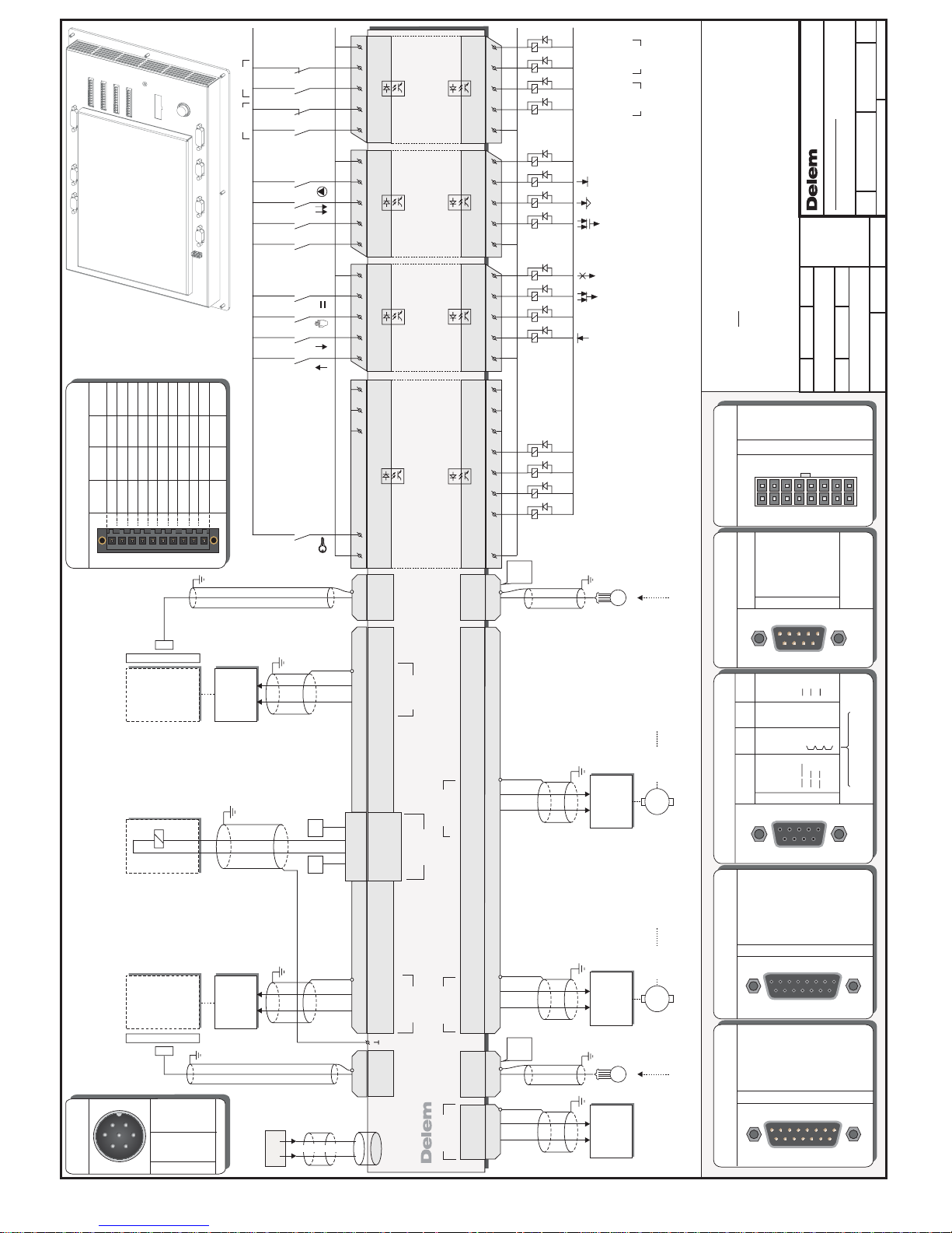
No unauthorized copying allowed
Format Number Issue
Note Redrawn
Redrawn
Date
Date
Date
Description
Description
Note
DrawnMeasures in mm,unless
otherwise specified
Scale
Luchthavenweg 42, 5657 EB
Eindhoven, the NETHERLANDS
A3
Page 1 /1
02-02-2007
24V
0V
POWER
0V
24V
HNF
Example connections:
Note 1 : Leave unconnected pins open.
Note 2 : 24V relais supply must be separated from 24V supply
ANALOG A
0V
I/O
24V
I/O
0V
I/O
24V
I/O
See drawing 8061-901
for mounting dimensions
Delem 1128-00N
ANALOG A
15 POLE MALE
1
OUTAN1 -10V...+10V
IN1B
IN1B 0V
OUTAN1 0V
N.C.
OUTAN2 -10V...+10V
REF1 10V
IN1A
IN1A 0V
2345678
9
IN2A
IN2A 0V
IN2B
IN2B 0V
OUTAN2 0V
REF2 10V
1011121314
15
12345678
9101112131415
CN7
1
Request to Send
Received Data
Clear to Send
Not connected
Transmitted Data
Signal Ground
2345678
9
12345
6789
SERIAL
9 POLE MALE
Not connected
Not connected
Not connected
CN16
12VSE
5VSE 5VDE
1
T0 (REF)
T0 (REF)
T2 (B)
T2 (B)
T1 (A)
+5V
+5V
In case of 12VSE
bridge pins 6,7,8 and 9
+5V
T1 (A)
+ 12V
+ 12V
GND
GND GND GND
T0T0T2T2T1
T1
T2
T1
T2T1/
///
/T0T0
2345678
9
12345
6789
ENCODER
9 POLE FEMALE
12VSE
5VSE 5VDE
1
T0 (REF)
T0 (REF)
T2 (B)
T2 (B)
T1 (A)
+5V
+5V
In case of 12VSE
bridge pins 6,7,8 and 9
+5V
T1 (A)
+ 12V
+ 12V
GND
GND GND GND
T0T0T2T2T1
T1
T2
T1
T2T1/
///
/T0T0
2345678
9
12345
6789
ENCODER
9 POLE FEMALE
CN10,14,9,12
INPUTS / OUTPUTS
10 POLE MALE
+24V
I/O-1
I/O-2
I/O-3
I/O-4
I/O-5
I/O-6
I/O-7
I/O-8
0V
+24V
OUT-9
OUT-10
OUT-11
OUT-12
IN-13
IN-14
IN-15
IN-16
0V
+24V
OUT-17
OUT-18
OUT-19
OUT-20
IN-21
IN-22
IN-23
IN-24
0V
+24V
OUT-25
OUT-26
OUT-27
OUT-28
IN-29
IN-30
IN-31
IN-32
0V
CN3 CN4 CN5 CN6
8061-0NN
DA-52
2
5
2
5
galvanic insulation
OUTPUTS
INPUTS
galvanic insulation
0V
COM
16151413
24V
1211109
COM
CN4
galvanic insulation
OUTPUTS
INPUTS
galvanic insulation
0V
COM
24
23
2221
24V
20191817
COM
CN5
galvanic insulation
OUTPUTS
INPUTS
galvanic insulation
0V
COM
32
31
3029
24V
28272625
COM
CN6
PIN 1-8 programmable
galvanic insulation
galvanic insulation
0V
COM
5432
24V
4321
COM
5
1
768
876
CN3
INPUTS
OUTPUTS
CN2
CN7
8061-104
VALVE
16 POLE MALE
1
Y1 0V
Y2 B-
P0V
Y1 A-
P-
Y1 24V
Y1 B-
Y2 0V
Y2 A-
2345678
9
Y2 24V
Y2 A+
Y2 B+
P 24V
Y1 A+
Y1 B+
1011121314
15
P+
16
910 111213141516
12345678
CN1
POWER
CN2 7 POLE MALE
N.C.
N.C.
SHIELD
24V
N.C.
N.C.
0V
34567
1
2
-
-
Ground
Power +
--Power -
1
2
3
4
5
6
7
ANALOG B
15 POLE FEMALE
1
Y1 -12V
Y1 +/-10V
P0V
Y1 +12V
P 0-10V
Y2 -12V
Y1 24V Max.100mA
Y1 LVDT
Y1 0V
2345678
9
Y2 LVDT
Y2 0V
Y2 +/-10V
Y2 +12V
Y2 24V Max.100mA
1011121314
15
12345678
9101112131415
CN8
Valve Enable
13-08-2007HNFA
A
CN10CN14CN16
CN20
CN9CN12
Encoder
AUX.2
Encoder
AUX.1
Analog A
COM 1
Encoder Y2
Encoder Y1
Analog B
USB 1
CN1
Valve
CN2
Power
Delem 8061-00N
CN3
CN4
CN5
CN6
Inputs/outputs
CN7
CN8
Function output F4
Function output F3
Function output F2
Function output F1
KEY LOCK
Crowning
P 0..10V
P0V
0-10V
0V
0V0-10V
Amplifier
7
8
Crowning.H.
ANALOG B
CN8
Crowning
Hydraulic
OUTAN2
-10V..+10V
OUTAN2
0V
+/-10V
0V
0V+/-10V
Amplifier
10
9
Servo
Axis 2
M
Axis 2
Axis 2
RSD
START
Axis 2
Axis 2
IN POSITION
OK
Feedback
Servo 2,
*See connection diagram: for details " OK & START"9087-102
*
*
Ref.9087-102 details "OK & START" added
Feedback
OUTAN1
-10V..+10V
OUTAN1
0V
+/-10V
0V
0V+/-10V
Amplifier
2
1
Servo
Axis 1
M
Axis 1
Axis 1
RSD
START
IN POSITION
OK
Axis 1
Axis 1
Servo 1,
*See connection diagram: for details " OK & START"9087-102
*
*
Ref.9087-102 details "OK & START" added
9P.
SUBD
Male
1 t/m 9
E
CN12
Feedback
Axis 2
Encoder
ENCODER
Auxiliary 2
1 t/m 9
E
ENCODER
Auxiliary 1
Feedback
Axis 1
CN9
Encoder
9P.
SUBD
Male
+/-10V
0V
0V +/-10V
Valve Y2
Amplifier
Valve Y2
1413
Y2 +/-10V
0V
ANALOG B
Linear
Scale Y2
1 t/m 9
Valve Y2
Y2-ext,
Note 4 : At the UDP the valve amplifiers should be disabled.
The fast closing command should only be activated when both
high retaining valves are opened.
The valve amplifiers should be enabled when the fast closing
command is activated.
CN14CN8
ENCODER
Y2
+/-10V
0V
0V +/-10V
Valve Y1
Amplifier
Valve Y1
65
ANALOG B
Y1 +/-10V
0V
Linear
Scale Y1
1 t/m 9
Valve Y1
Note 4 : At the UDP the valve amplifiers should be disabled.
The fast closing command should only be activated when both
high retaining valves are opened.
The valve amplifiers should be enabled when the fast closing
command is activated.
Y1-ext,
CN10 CN8
ENCODER
Y1
81615 7
24V
System
Pressure
0V
System
Pressure
P+
P-P24V
P0V
OPENING
PRESSING
MANUAL
PARALLEL
T (Tandem)
C (step
Change)
PUMP
ER
(End of Relaxtion)
UDP
(Upper Dead Point)
CNC START
MUTE
CLAMP
2nd MUTE
CNC READY
LDP
(Lower Dead Point)
VALV E
Note3:Do place a diode across valves.not
FAST
CLOSING
P,
CN1
Page 27
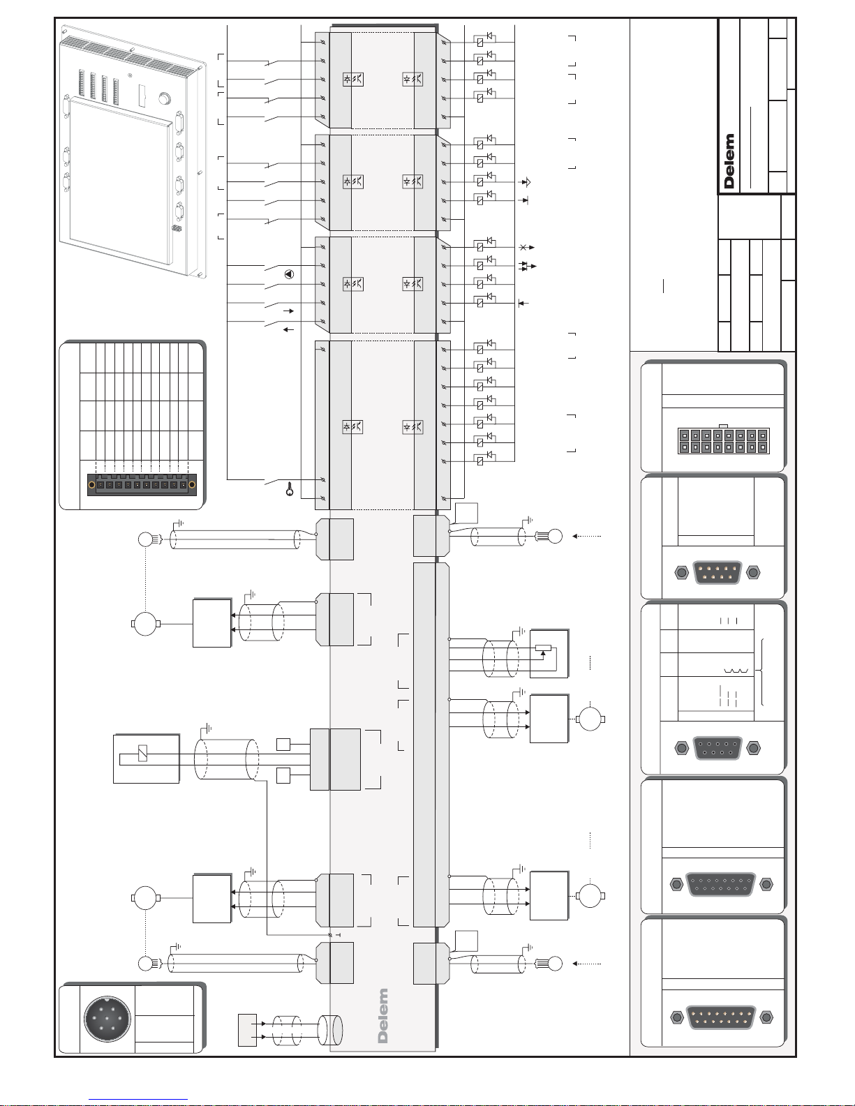
No unauthorized copying allowed
Format Number Issue
Note Redrawn
Redrawn
Date
Date
Date
Description
Description
Note
DrawnMeasures in mm,unless
otherwise specified
Scale
Luchthavenweg 42, 5657 EB
Eindhoven, the NETHERLANDS
A3
Page 1 /1
02-06-2010
24V
0V
POWER
0V
24V
HNF
Example connections:
Note 1 : Leave unconnected pins open.
Note 2 : 24V relais supply must be separated from 24V supply
ANALOG A
0V
I/O
24V
I/O
0V
I/O
24V
I/O
See drawing 8061-901
for mounting dimensions
Delem 1128-00N
ANALOG A
15 POLE MALE
1
OUTAN1 -10V...+10V
IN1B
IN1B 0V
OUTAN1 0V
N.C.
OUTAN2 -10V...+10V
REF1 10V
IN1A
IN1A 0V
2345678
9
IN2A
IN2A 0V
IN2B
IN2B 0V
OUTAN2 0V
REF2 10V
1011121314
15
12345678
9101112131415
CN7
1
Request to Send
Received Data
Clear to Send
Not connected
Transmitted Data
Signal Ground
2345678
9
12345
6789
SERIAL
9 POLE MALE
Not connected
Not connected
Not connected
CN16
12VSE
5VSE 5VDE
1
T0 (REF)
T0 (REF)
T2 (B)
T2 (B)
T1 (A)
+5V
+5V
In case of 12VSE
bridge pins 6,7,8 and 9
+5V
T1 (A)
+ 12V
+ 12V
GND
GND GND GND
T0T0T2T2T1
T1
T2
T1
T2T1/
///
/T0T0
2345678
9
12345
6789
ENCODER
9 POLE FEMALE
12VSE
5VSE 5VDE
1
T0 (REF)
T0 (REF)
T2 (B)
T2 (B)
T1 (A)
+5V
+5V
In case of 12VSE
bridge pins 6,7,8 and 9
+5V
T1 (A)
+ 12V
+ 12V
GND
GND GND GND
T0T0T2T2T1
T1
T2
T1
T2T1/
///
/T0T0
2345678
9
12345
6789
ENCODER
9 POLE FEMALE
CN10,14,9,12
INPUTS / OUTPUTS
10 POLE MALE
+24V
I/O-1
I/O-2
I/O-3
I/O-4
I/O-5
I/O-6
I/O-7
I/O-8
0V
+24V
OUT-9
OUT-10
OUT-11
OUT-12
IN-13
IN-14
IN-15
IN-16
0V
+24V
OUT-17
OUT-18
OUT-19
OUT-20
IN-21
IN-22
IN-23
IN-24
0V
+24V
OUT-25
OUT-26
OUT-27
OUT-28
IN-29
IN-30
IN-31
IN-32
0V
CN3 CN4 CN5 CN6
8061-0NN
DA-52
2
5
2
5
galvanic insulation
OUTPUTS
INPUTS
galvanic insulation
0V
COM
16151413
24V
1211109
COM
CN4
galvanic insulation
OUTPUTS
INPUTS
galvanic insulation
0V
COM
24
23
2221
24V
20191817
COM
CN5
galvanic insulation
OUTPUTS
INPUTS
galvanic insulation
0V
COM
32
31
3029
24V
28272625
COM
CN6
PIN 1-8 programmable
galvanic insulation
galvanic insulation
0V
COM
5432
24V
4321
COM
5
1
768
876
CN3
INPUTS
OUTPUTS
CN2
CN7
8061-105
VALVE
16 POLE MALE
1
Y1 0V
Y2 B-
P0V
Y1 A-
P-
Y1 24V
Y1 B-
Y2 0V
Y2 A-
2345678
9
Y2 24V
Y2 A+
Y2 B+
P 24V
Y1 A+
Y1 B+
1011121314
15
P+
16
910 111213141516
12345678
CN1
POWER
CN2 7 POLE MALE
N.C.
N.C.
SHIELD
24V
N.C.
N.C.
0V
34567
1
2
-
-
Ground
Power +
--Power -
1
2
3
4
5
6
7
ANALOG B
15 POLE FEMALE
1
Y1 -12V
Y1 +/-10V
P0V
Y1 +12V
P 0-10V
Y2 -12V
Y1 24V Max.100mA
Y1 LVDT
Y1 0V
2345678
9
Y2 LVDT
Y2 0V
Y2 +/-10V
Y2 +12V
Y2 24V Max.100mA
1011121314
15
12345678
9101112131415
CN8
Valve Enable
14-06-2010HNFA
A
CN10CN14CN16
CN20
CN9CN12
Encoder
AUX.2
Encoder
AUX.1
Analog A
COM 1
Encoder Y2
Encoder Y1
Analog B
USB 1
CN1
Valve
CN2
Power
Delem 8061-00N
CN3
CN4
CN5
CN6
Inputs/outputs
CN7
CN8
Function output F4
Function output F1
KEY LOCK
Potentiometer
10K
10V
0-10V
0V
11 1 2
13
IN2A
IN2A
0V
REF2
10V
A<
A>
Crowning
Crowning
Crowning.M.
Crowning
+/-10V
0V
0V +/-10V
Axis 3
Amplifier
Axis 3
1413
Y2 +/-10V
0V
ANALOG B
Axis 3
CN8
M
Servo 3,
RSD
Axis 3
*
IN POSITION
Axis 3
*
OUTAN2
-10V..+10V
OUTAN2
0V
+/-10V
0V
0V+/-10V
Amplifier
10
9
Servo
Axis 2
M
Axis 2
Axis 2
RSD
START
Axis 2
Axis 2
IN POSITION
OK
Feedback
Servo 2,
*See connection diagram: for details " OK & START"9087-102
*
*
Ref.9087-102 details "OK & START" added
Feedback
OUTAN1
-10V..+10V
OUTAN1
0V
+/-10V
0V
0V+/-10V
Amplifier
2
1
Servo
Axis 1
M
Axis 1
Axis 1
RSD
START
IN POSITION
OK
Axis 1
Axis 1
Servo 1,
*See connection diagram: for details " OK & START"9087-102
*
*
Ref.9087-102 details "OK & START" added
1 t/m 9
CN14
ENCODER
Axis 3
Encoder Axis 3
E
Feedback
9P.
SUBD
Male
1 t/m 9
E
CN12
Feedback
Axis 2
Encoder
ENCODER
Auxiliary 2
1 t/m 9
E
ENCODER
Auxiliary 1
Feedback
Axis 1
CN9
Encoder
9P.
SUBD
Male
Y-Axis
Encoder-YM
1 t/m 9
ENCODER
YM
YM-conv.,
CN10
E
Feedback
M
+/-10V
0V
0V +/-10V
Axis Y
Amplifier
Axis Y
65
ANALOG B
Y1 +/-10V
0V
CN8
RSD
START
Axis YM
Axis YM
IN POSITION
OK
81615 7
24V
System
Pressure
0V
System
Pressure
P+
P-P24V
P0V
C (step
Change)
PUMP
UDP
(Upper Dead Point)
CNC START
MUTE
CLAMP
CNC READY
LDP
(Lower Dead Point)
CLOSING
OPENING
RETRACT
VALV E
Note3:Do place a diode across valves.not
P-int.conv.,
CN1
ED
(End of Dwell)
ABB
()Anti BackBend
Page 28

Delem
V0614, 2.1
Part II - Machine settings
This section will describe the necessary settings of a DA-52s control regarding machine
settings.
Page 29
Delem
V0614, 2.2
1. The machine parameters
1.1. Machine parameters menu
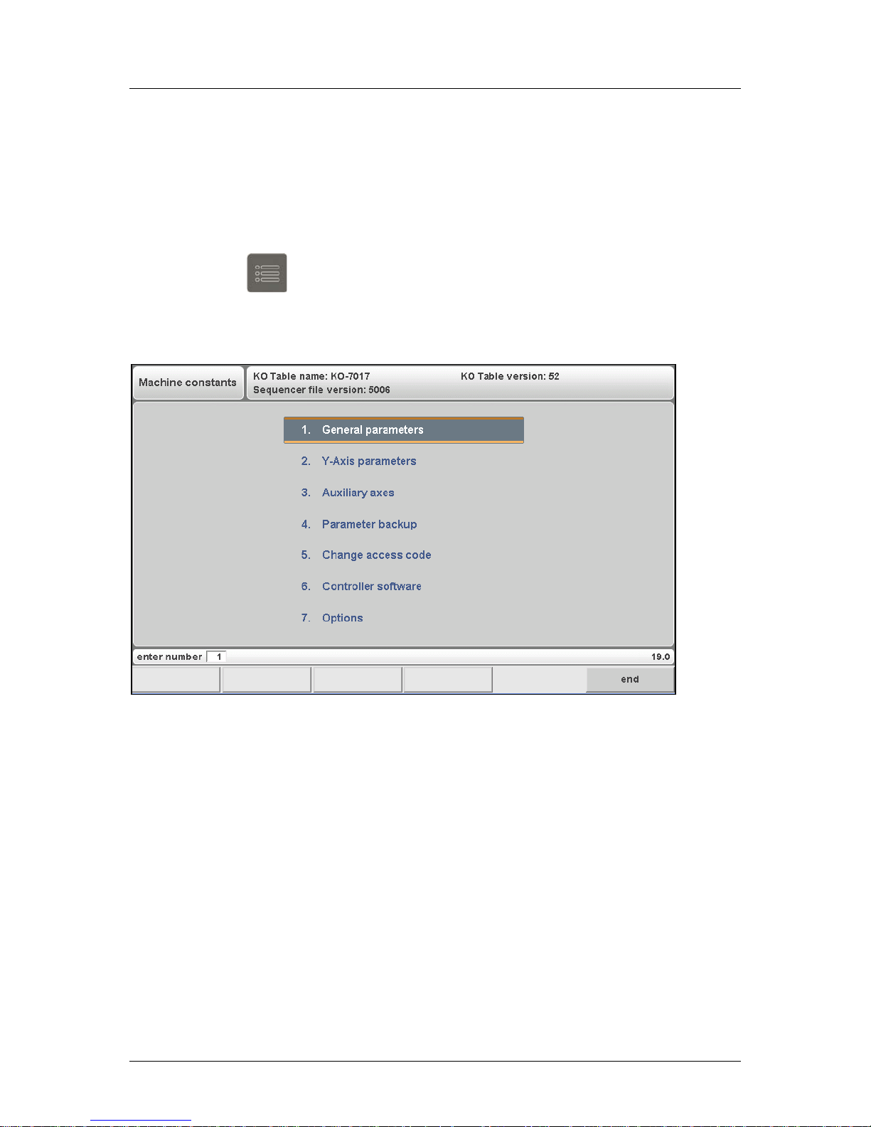
To open the machine parameters menu:
• press the key
to go to the program constants
• on the first parameter, enter the access code 14753
The main menu of the machine parameters appears.
For a description of menu 1 to 4 we refer to the Delem machine parameter manual [1]. In this
chapter, the installation of new software and options is explained.
Page 30
Delem
V0614, 2.3
1.2. Update control
1.2.1. Update procedure
The control can be upgraded with new software. Before you commence an update make sure
you have a backup of all your data, such as products, tools, machine parameters, etc.
New software can be loaded from a portable USB drive. A CD-ROM with the latest control
software can be requested at Delem. It contains all software necessary to perform an update.
To prepare for an update, copy the contents to the USB disk.
Note:
• When the update program has finished the installation procedure, the control needs to
reboot. Therefore, do not disconnect the USB disk until the update has been completed.
The update procedure runs as follows:
• Insert the portable USB Drive into an available USB port;
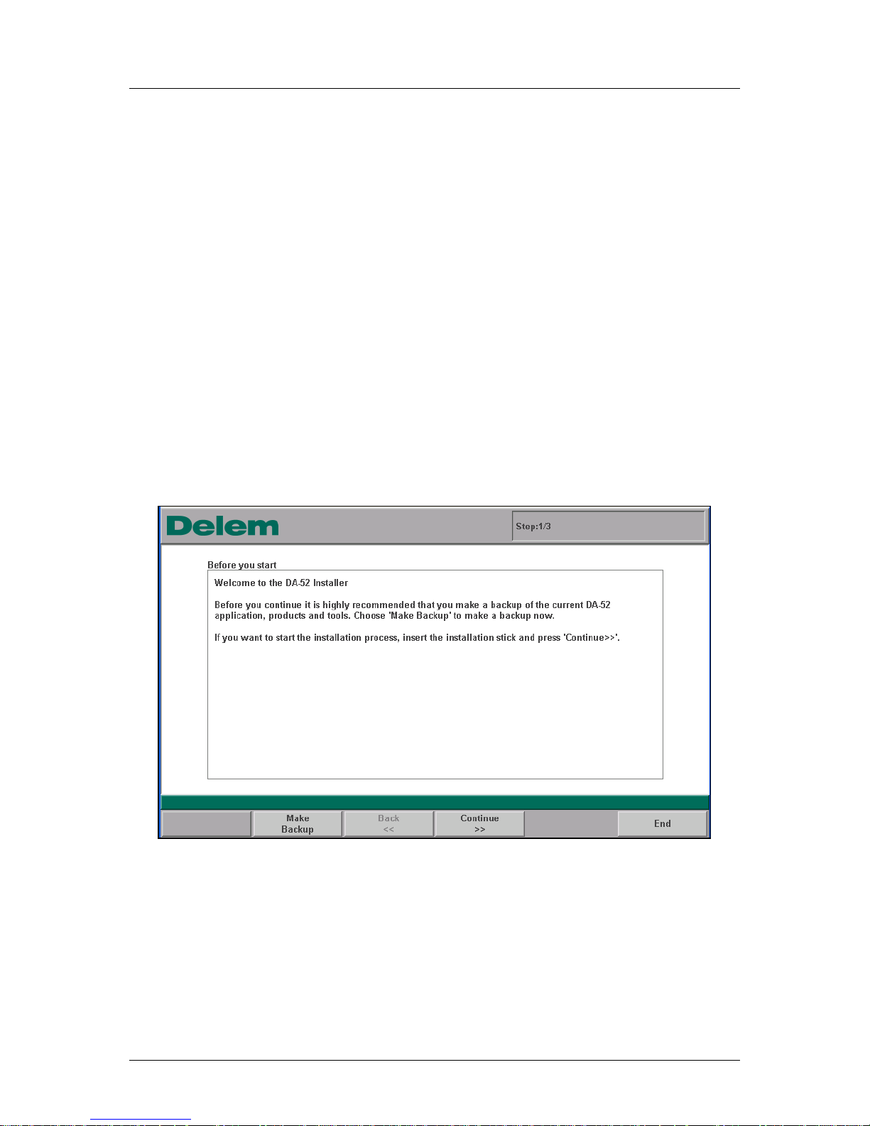
• on the control, go to the machine parameter menu and choose "Controller software".
The control will search for a valid update set on the USB disk. If it is found, the installation
program will start:
Figure 1.a
The program starts with a recommendation to make a backup of the currently installed
software. See the next section for more about the backup procedure.
Although a backup is recommended here, you are not obliged to follow this advise. If you do
not wish to make a backup, press the key "N" (Continue>>) to proceed.
Page 31
Delem
V0614, 2.4
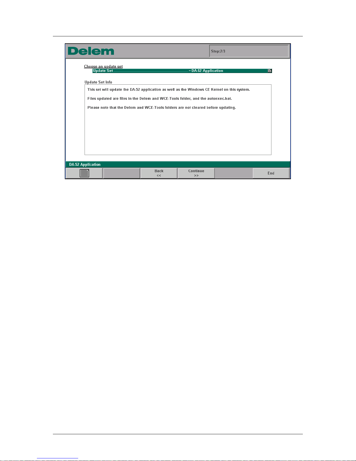
Figure 1.b
The installation program will now check for valid software that can be installed on the control.
In case various update sets are present, it is possible to select one of them through the
listbox. The standard updater offers several update sets:
• DA-52 Application
• DA-52 Factory Default
• etc...
A set called ‘DA-52s Application’ is used to upgrade the control Operating system and the DA
application, without affecting the existing user data (products, tools, materials) on the control.
A set called ‘DA-52s Factory Default’ is typically used for first time installation of all software
on a DA-52s control, including example products, tools and materials. If this update set is
used on a control which already contains such user data, this data may be overwritten.
If the correct update set is shown, press “Continue>>” to continue.
Page 32
Delem
V0614, 2.5
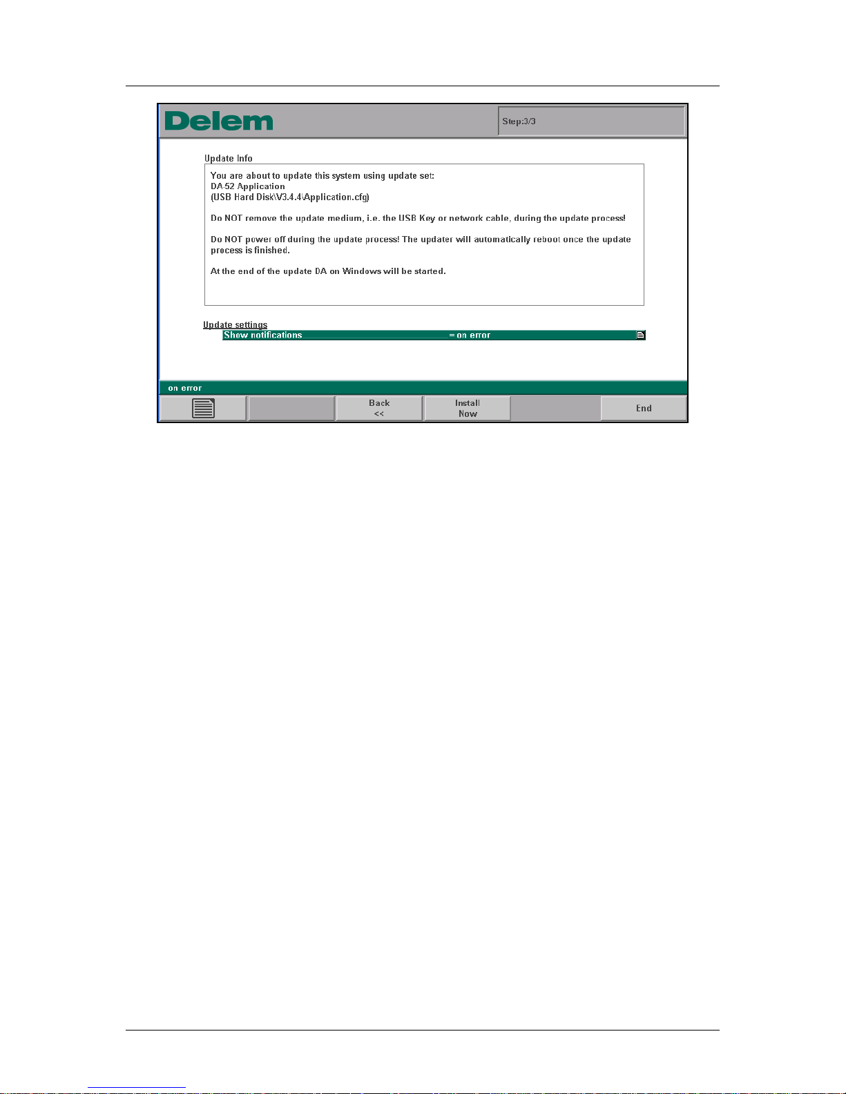
Figure 1.c
This third window shows the final information about the software update and a warning not to
interrupt the update process. On the bottom, two parameters are available to modify the
update behaviour:
Show notifications
Determine when messages must be displayed during the update.
Always: the updater will produce a message window after each stage of the update. With
this setting on, the update process can be monitored in detail.
On error: you will not receive intermittent messages, unless an error has occurred.
Normally the setting 'on error' will suffice, unless you wish to follow the update process
closely.
Automatic reboot when finished
Choose to let the control restart automatically when the update process has finished: yes or
no.
Press the key ‘Install now’ to start the update process.
Page 33
Delem
V0614, 2.6
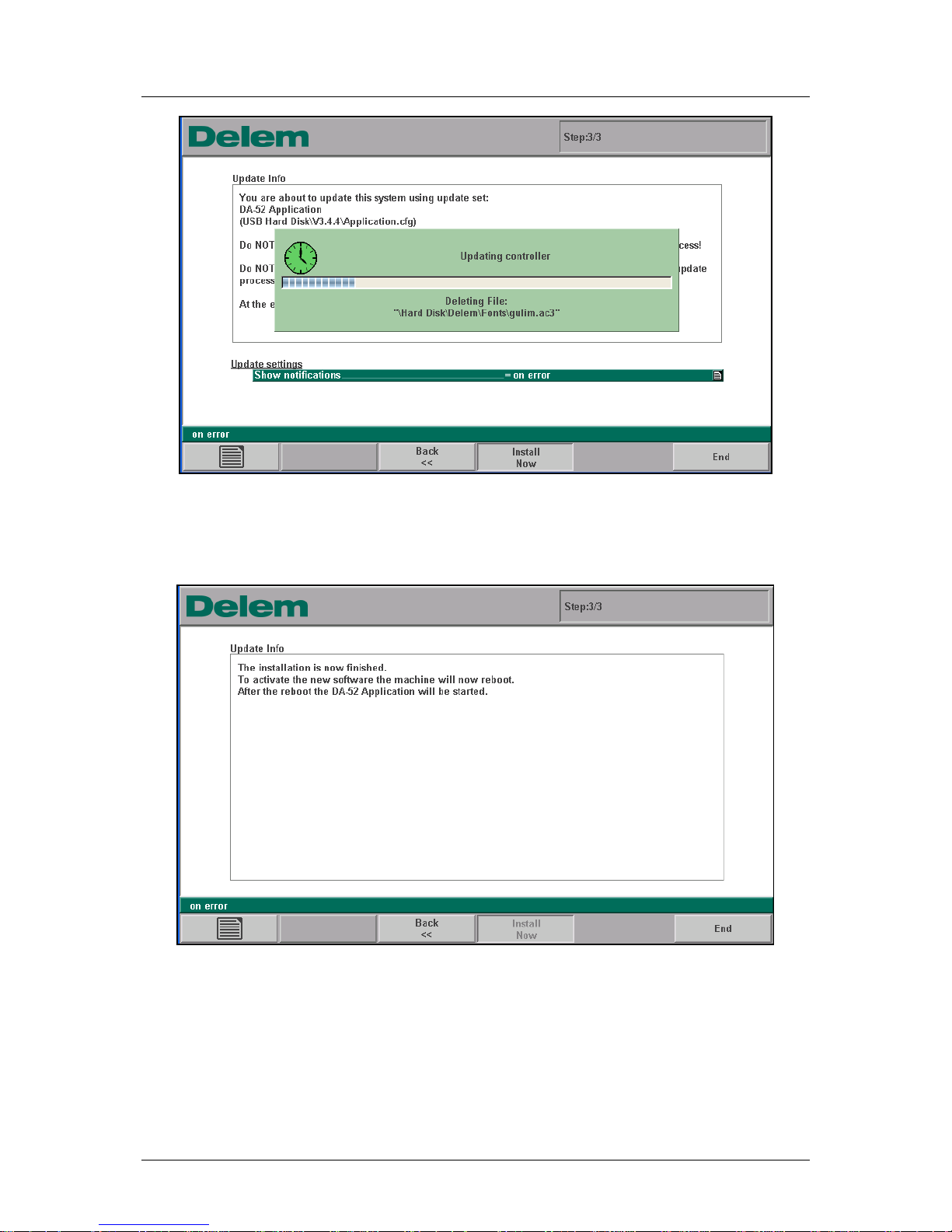
Figure 1.d
When the update process is finished, the control will reboot or (depending on the setting
'Automatic reboot') show a message the control should be restarted.
Figure 1.e
In case the update stops when finished, press the END key to start the control. After this
reboot, the control will start as usual with the Delem DA application.
Page 34
Delem
V0614, 2.7
1.2.2. Backup/restore the application
Backup
The update program offers the possibility to make a backup of the current software set that is
installed on the control. This way, the current application is saved with its existing settings
before the software is updated. With this procedure all data is stored:
• the Windows system
• DA application
• license files for control options
• products, tools and machine parameters
The software is saved as an update set, so it can be re-installed on the current control.
As shown in the previous section, the Updater offers the possibility of a backup on start-up.
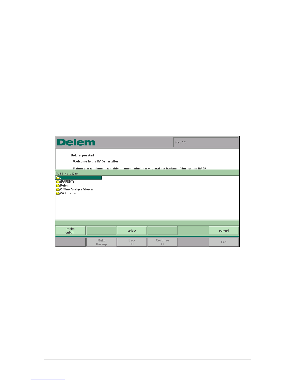
When the button ‘Make backup’ has been pressed, the following screen appears:
Figure 1.f
The Updater asks for a directory to store the application software in, anywhere on the USB
disk. It is also possible to create a new subdirectory to store the system in.
Warning:
If the selected directory already contains an update set, these files will be replaced with the
current backup.
As soon as the backup is complete, the program switches to step 2/3 of the update program
to choose an update configuration. This is described in the previous section.
Restore
To restore software, simply run the update set that was created with the backup as described
above.
Page 35
Delem
V0614, 2.8
1.2.3. Modify the update
As shown in section 2.5.1, it is possible to have various update sets available with which you
can update the control. Normally, the standard ‘DA-52s Application’ is sufficient to update
your control. If necessary, you can create your own update set.
An update set is described by a configuration text file, in which you can determine which
parts of your system are to be updated. Such a configuration file is recognised by the
extension ‘.cfg’ in the filename. It must be present in the same directory as the updater
program. When the updater program is started it searches the USB drive for all files which
have such an extension in their filename. In the second window of the updater program, all
available update sets can be selected with the dropdown list.
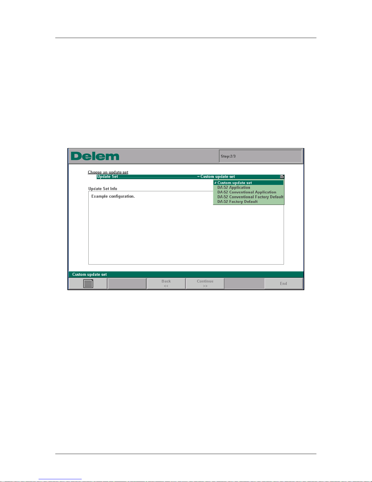
Figure 1.g
The names you see in the list are retrieved from each available configuration file.
You can change the content to add items to the standard Delem update set or create a small
set which can be run separately, after the Delem update. A .cfg file contains six sections:
1. [INFO] Name and information of the update set
2. [FILEDEL] Files to be deleted
3. [FILECPY] Files to be added or replaced
4. [REGDEL] Registry entries to be deleted
5. [REGADD] Registry entries to be added or changed
6. [EXECUTE] Executables to be run
Updater.exe will always perform the actions in these sections in the order shown above,
regardless of the order in the .cfg file.
You can create any number of .cfg files and put them next to the Delem update.cfg, or even
remove the Delem update.cfg. The Updater will automatically show all update sets to the
user. The [INFO] section of a .cfg file gives information about the update. The first line after
the [INFO] gives the title of the update set, which is displayed in the dropdown list in the
Page 36

Delem
V0614, 2.9
updater. The lines following after that give additional information which is displayed in the
updater window.
The update program is delivered with a text file, called ‘UpdaterReadme.txt’. Also, the
standard configuration file ‘Application.cfg’ contains a lot of comment which describes the
possibilities of the update set. Study these files closely for more information.
Page 37
Delem
V0614, 2.10
1.3. Option installation
1.3.1. Request option on the control
It is possible to install software options on the control. Options can be requested at Delem.
Options for a DA-52s control can be purchased at any moment. It is done by buying an
‘Option Voucher’ for a specific function (e.g. 2nd servo axis). A new option voucher is valid
for any DA-52s control. Hence, it is possible to buy one or more option vouchers and keep
them in stock until the option becomes necessary on a control.
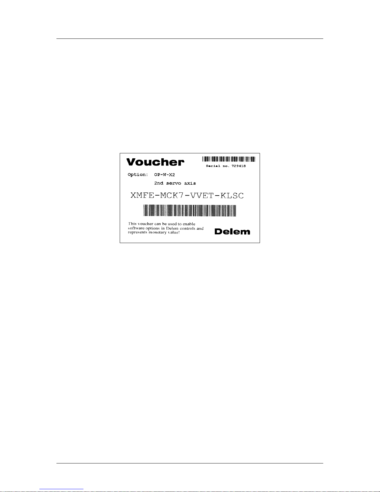
An option voucher looks as follows:
Figure 1.h
At the top, an option identifier and a short description is placed. In the middle, a 16-digit
number is placed, divided by dashes. When requesting an option you must enter this number
exactly as it is shown, including the dashes.
When an option must be installed on a control, you can take a voucher for the specific
function and request the option on the control. Once an option is requested on a control, the
control will receive a certificate (license) for the requested option. From that moment on, the
voucher is linked to this control, it cannot be used anymore on any other control.
If necessary, the option can be requested many times. Should a certificate get lost somehow,
simply request the same option again for the same control.
The procedure to install an option runs as follows:
• Go to the machine parameters menu.
• Choose menu 7: 'Options'.
Page 38
Delem
V0614, 2.11
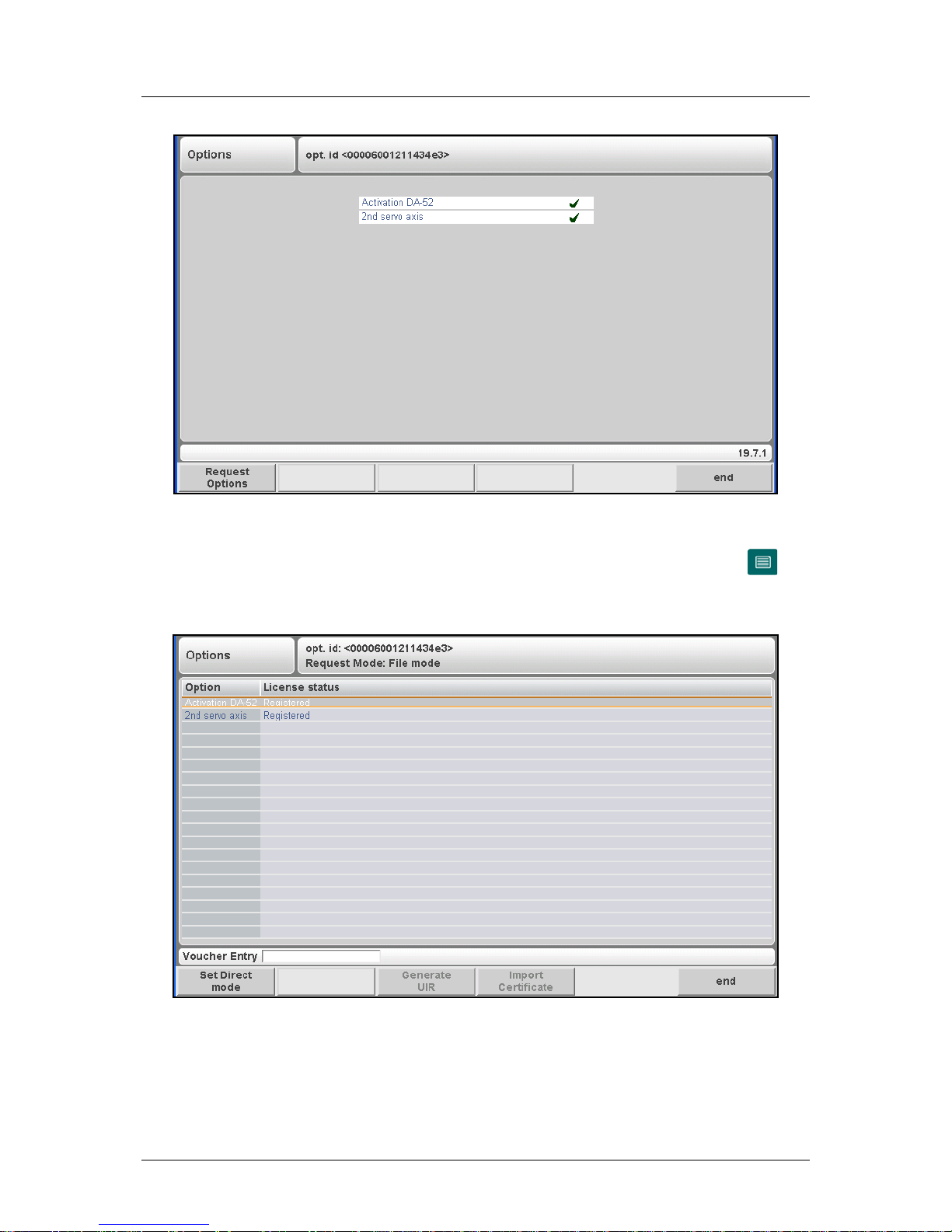
Figure 1.i
This window shows which options are available. To activate an option, press the key
(Request options) to start option installation.
When pressed, the screen looks as follows:
Figure 1.j
At the top of the screen, the serial number of the control is displayed.
On the left side of the screen, a list of possible options is displayed for the control. If an
option is already enabled, the word ‘registered’ is displayed in the second column.
Page 39

Delem
V0614, 2.12
File mode
To install an option:
• go with the cursor to the desired option;
• plug in a USB-stick;
• enter the 16-digit option voucher number in the field ‘Voucher entry’ and press the
button ‘Generate UIR’: a text file is generated on the USB-stick, which contains the
code to request a license, a UIR file;
• submit the contents of the UIR text file to the Delem Certificate Server
(certificates.delem.com); this is explained in detail in the next paragraph;
• obtain a certificate file from Delem and put it on a USB disk or on the control disk;
• in the option program, select the requested option and press the button ‘import
certificate’.
• in the file dialog that appears, select the received certificate file (anywhere on USB or
hard disk) and press ‘OK’.
• When successful, the message ‘license successfully imported’ appears and the license
status of the option will change to ‘registered’.
• Press 'END' to return to the menu of the machine parameters.
Page 40
Delem
V0614, 2.13
1.3.2. Request option code at Delem
The UIR file that was generated by the option program must be submitted to the Delem
Certificate Server. From this UIR file a certificate file is generated. This certificate file can
then be used to enable the option on the control.
There are different ways to send the UIR file to Delem. The simplest (and slowest) way is put
the file on a portable disk and send this to Delem. After a certain period, you will receive a
disk with the license file.
Another method is to send the UIR file by e-mail to Delem and request the option. You will
receive a license file shortly.
The third method is to use an internet connection and connect to a special Delem license
website: http://certificates.delem.com.
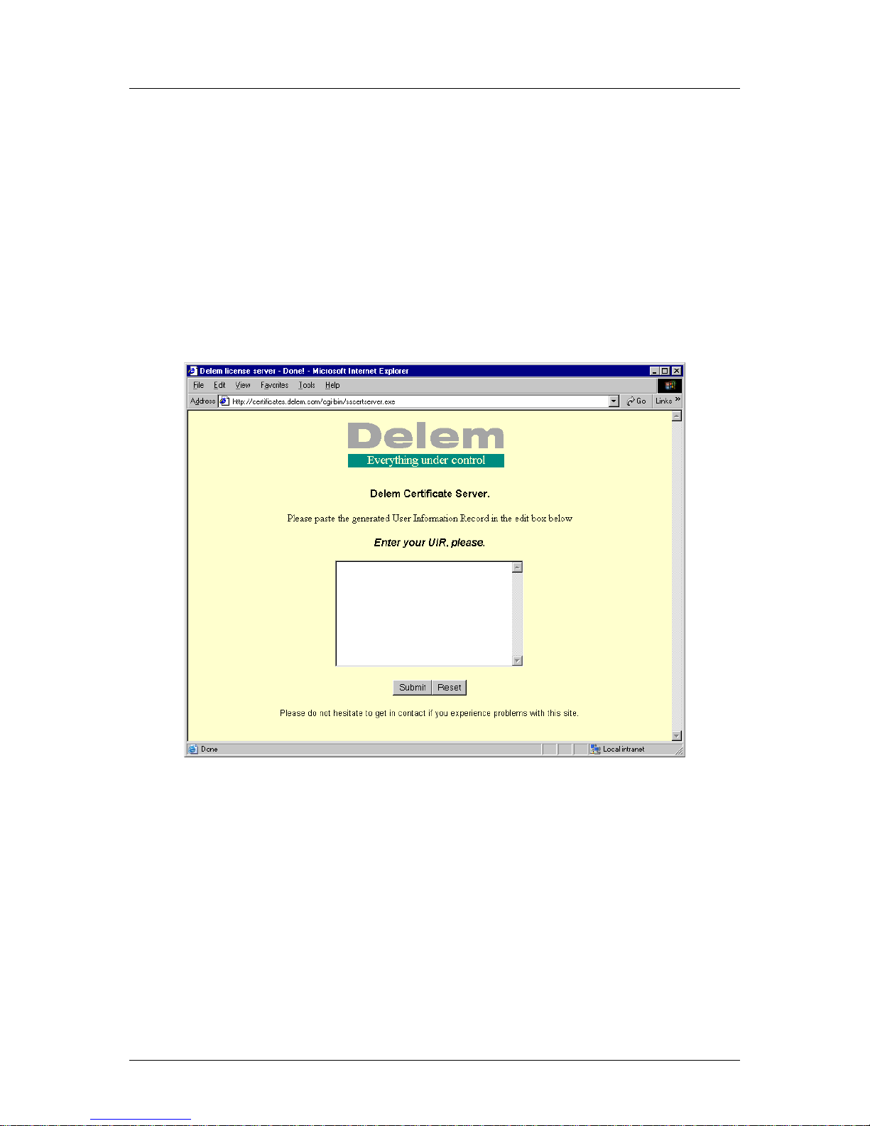
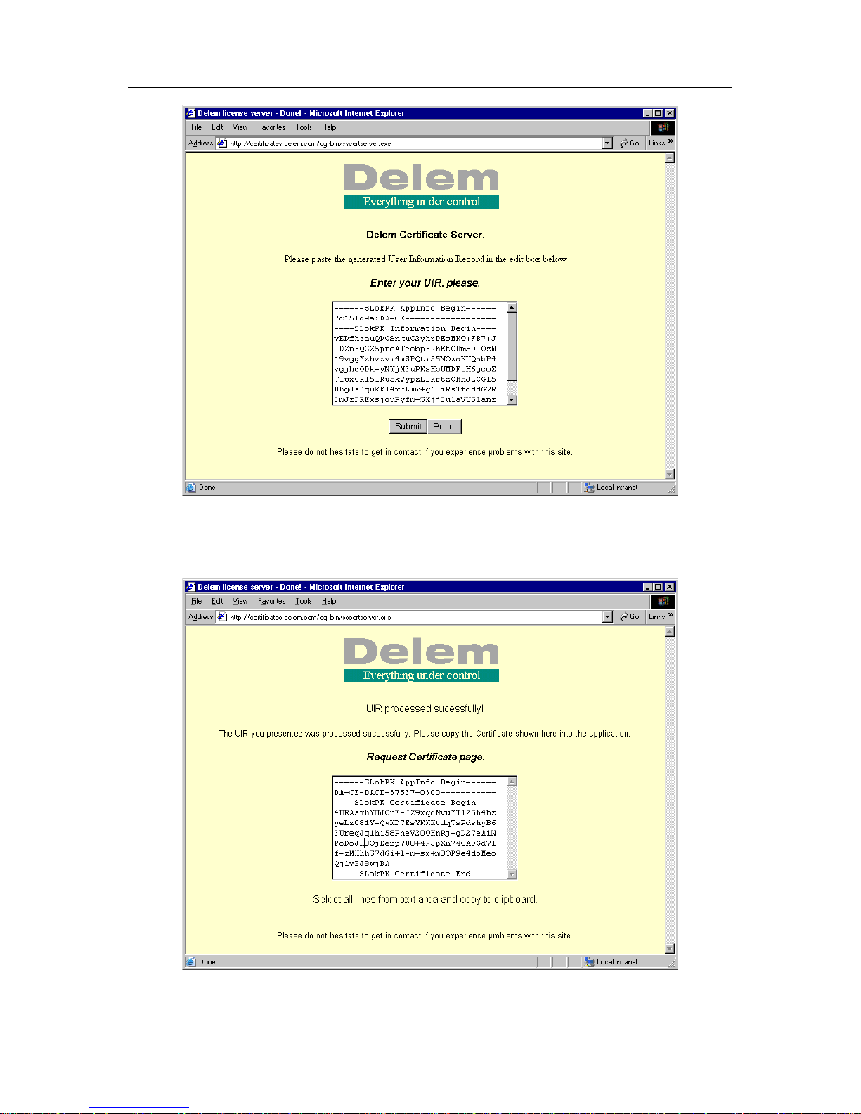
Figure 1.k
On this site, you can directly request the license code. Make sure the generated UIR file is
accessible from your internet PC. Proceed as follows:
• open the UIR file and copy all text to the clipboard memory;
• in the browser, paste the clipboard contents into the license field; it should look as
follows:
Page 41
Delem
V0614, 2.14
Figure 1.l
• press the button ‘submit’ below the field;
Figure 1.m
Page 42
Delem
V0614, 2.15
You will get a message whether or not the code has been processed successfully.
• the text has changed: copy this new text to the clipboard;
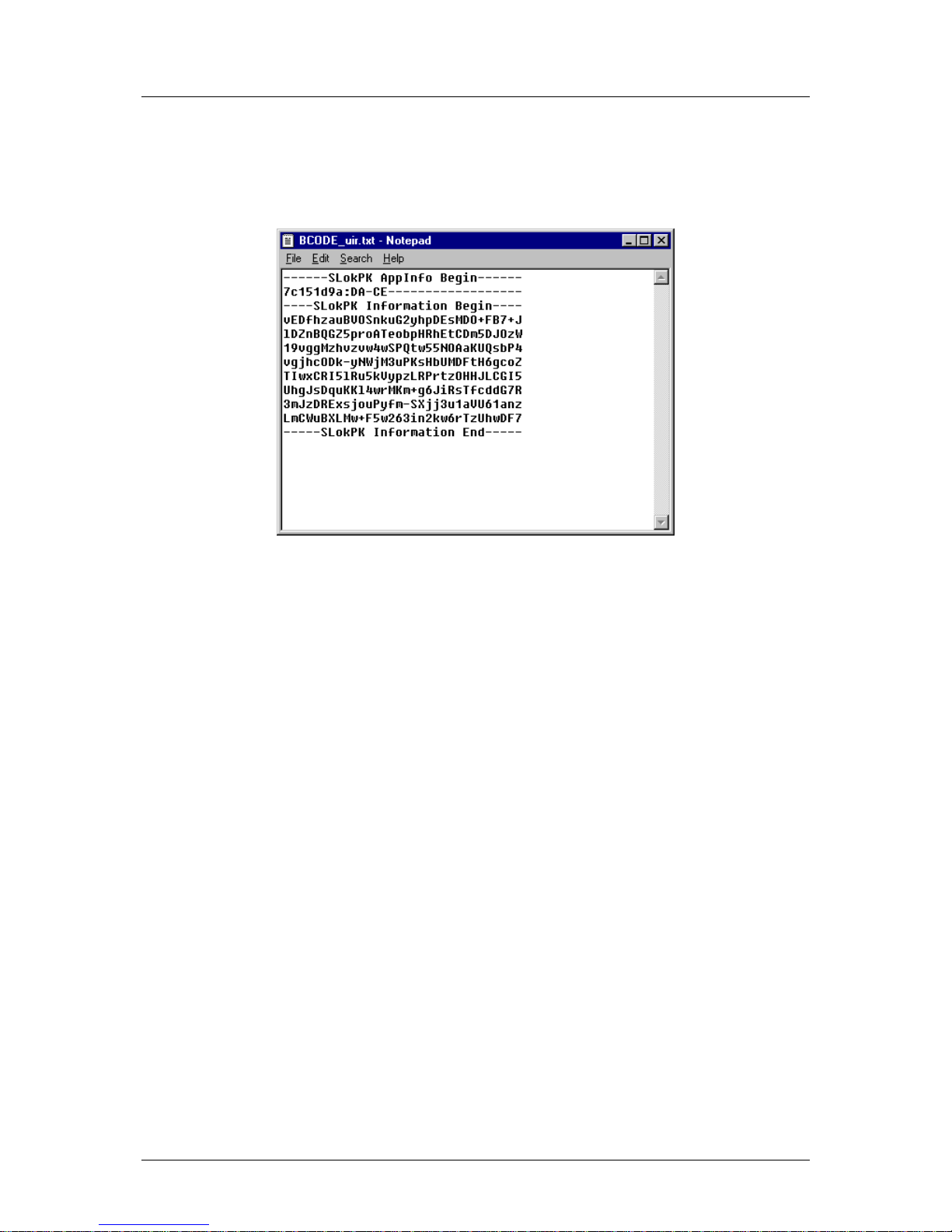
• open a new empty text document, paste the clipboards contents and save this as a
new text file: this is your certificate file;
Figure 1.n
• transfer this file to the control (USB disk);
• resume with the option procedure as described in the previous section.
When a license has been registered, the file with the registration code is stored on the control
disk, in the directory \Hard Disk\Delem\Licenses. The file has the extension ‘.lic’. It is possible
to copy these files to a USB disk. When the control has been re-installed or rescued, the
license files can be copied back into the ‘Licenses’ directory to enable the control with its
options again. This can work faster than having to request all licenses again.
Page 43
Delem
V0614, 2.16
2. Windows tasks
2.1. Windows introduction
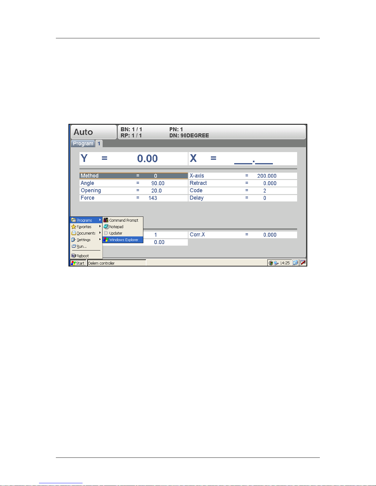
To be able to operate the Windows system, an external keyboard and mouse must be
connected. Press the Windows key on the keyboard to activate the Windows menu.
Figure 2.a
To switch to Windows without opening any application, click on the pencil symbol in the lower
right corner of the screen. The Delem control application is switched to the background, but
remains active.
To activate a certain application, click on the Start button in the lower left corner of the
screen. Choose an application from the list. The list of available applications in your Start
menu depends on the control type.
For some of the machine tasks this procedure will be necessary, so be sure to familiarise
yourself with this routine.
The ‘Reboot’ command right above the Start button serves to restart the control. It will be
indicated in this manual when this is necessary.
Page 44
Delem
V0614, 2.17
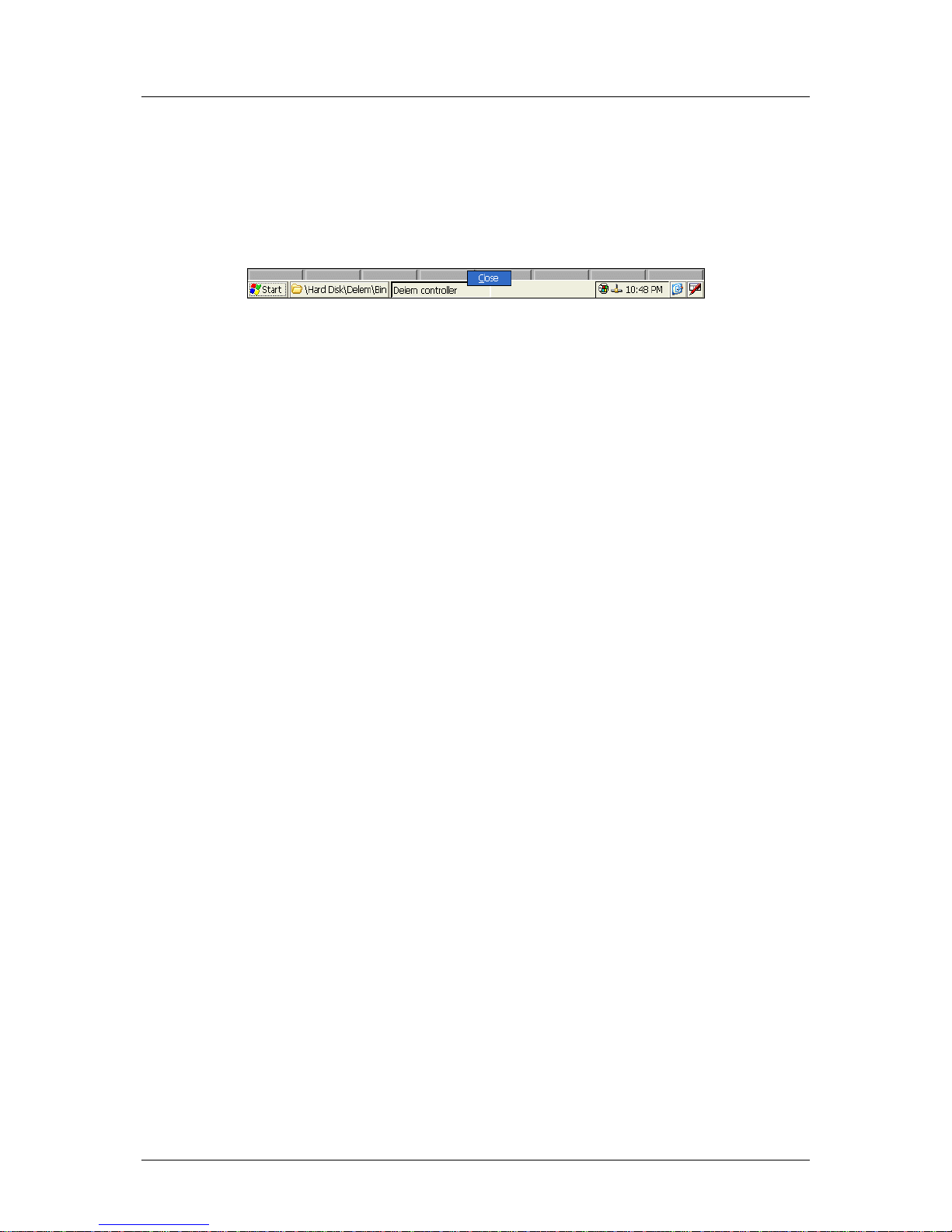
The Delem control application can be switched off. The application is switched off as follows:
• move the mouse to the lower edge of the screen: the Windows taskbar appears;
• move the pointer to the expression ‘Delem controller’;
• click on the right mouse button: a small pop-up box appears, with the instruction ‘close’
(see figure below);
• click on ‘close’: the control application is stopped.
Figure 2.b
To restart the control application: go to the Windows Start Menu and choose ‘Reboot’.
Page 45

Delem
V0614, 2.18
2.2. Directory structure
The data on the control has been organised into directories, like on a computer. Within the
graphical interface of Windows, the term ‘Folder’ is used.
Most directories on the Windows desktop are volatile directories, which means they are lost
when the control is shut off and are re-created when the control is started. Only the directory
‘Hard Disk’ is permanent, because it refers to the embedded flash memory of the control.
This flash memory is the internal storage device of the control. In this manual the expression
‘hard disk’ will be used to indicate this internal storage device.
Any file that must be stored for later use, should be stored somewhere in the directory tree of
the hard disk.
Some important directories:
\Hard Disk\Delem\Bin
This directory contains the Delem control application files. The control application
‘Delem.exe’ is automatically started when the control is activated. Furthermore the Delem
sequencer file and the KO-Table are located here.
\Hard Disk\Delem\Data
Directory with the ‘products’ and ‘tools’ subdirectories, which contain all products and tools
for this control.
\Hard Disk\WCE-Tools
This directory contains several additional Delem utilities.
\Hard Disk\Delem\Licenses
Directory with license files. See also section 3.3 about option installation.
Page 46
Delem
V0614, 2.19
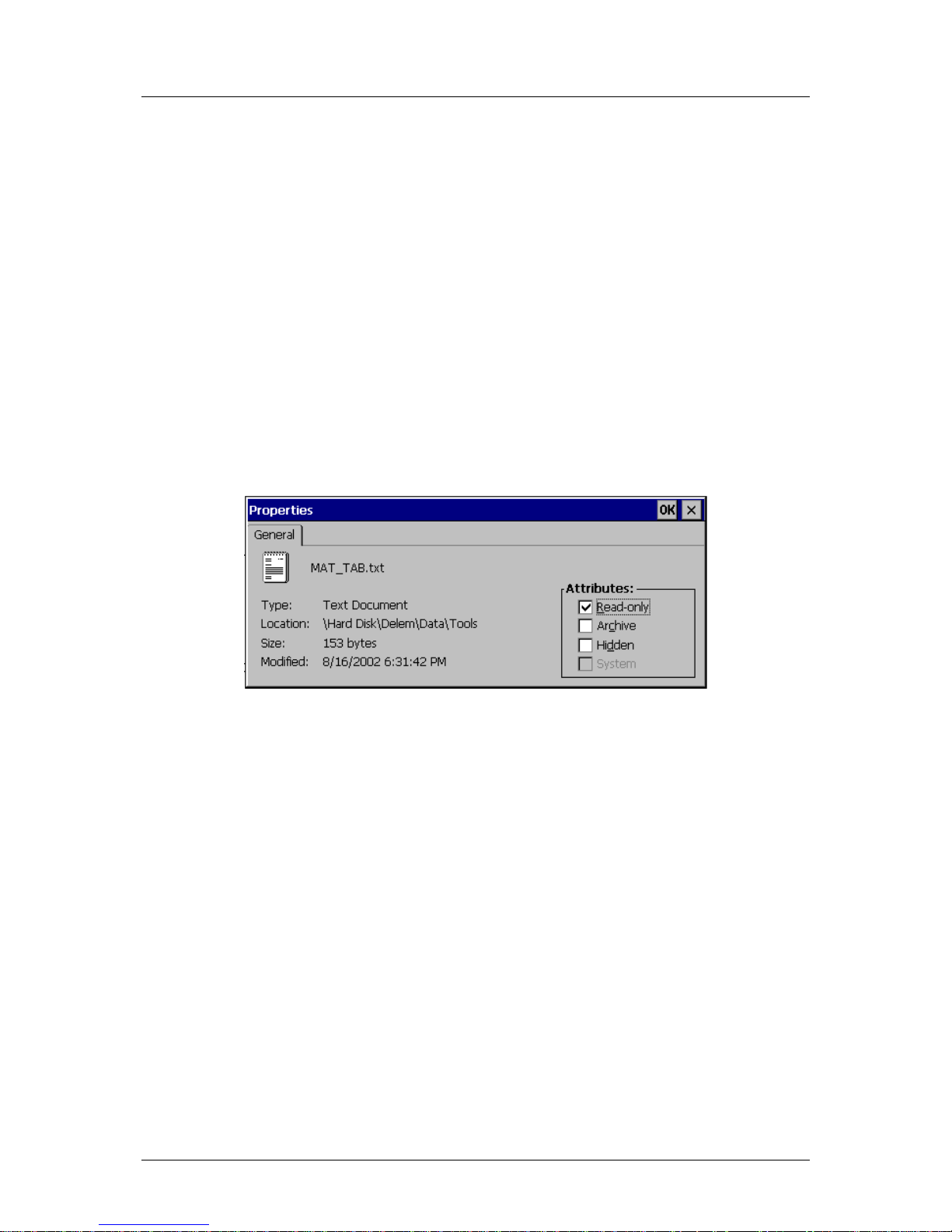
2.3. Important files
A lot of control settings are stored in files, which are located on the hard disk of the control.
This is the case for the Delem application as well as for the Windows platform. Whenever the
control is (re)started, the software will search for these files and retrieve the last saved
settings.
If for any reason the settings are mixed up, it is possible to delete these files. At the next
start-up, the control will assume its default settings. This should only be done as a last
remedy, if the control does not function properly anymore.
If the s ettings are correct and you do not wish unauthorised people to change them, it is
possible to set these files as read-only files. This way settings cannot be changed. To set the
file to read-only, proceed as follows:
• open the Windows Explorer
• browse to the correct location (directory) to find the file
• click on the desired file
• open the File menu and select ‘properties’
A window like the one shown below should appear:
Figure 2.c
In the ‘attributes’ section of the window, mark the setting ‘Read-only’ and click on ‘OK’ to
save the setting. The file cannot be altered anymore.
In the example above, the properties of the material table are shown. Materials are
programmed in the menu ‘program constants’ of the control. If material properties are
changed or materials are added or deleted, the information is written to this file. If the file is
set to read-only, any attempt by an operator to change material properties or to add or delete
materials will be ignored.
Page 47
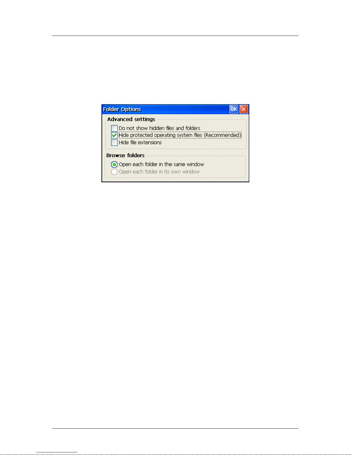
Delem
V0614, 2.20
Another possibility is to mark files as ‘hidden’. A hidden file is not shown in the Windows
Explorer and as such it is protected against unauthorised user actions. A hidden file can also
not be opened from within Windows applications, such as Wordpad. The Delem application
can still open a necessary settings file, even though it is hidden.
If an authorised person wishes to access hidden files, the Windows Explorer has the setting
to view all files. From within the Explorer, open the View menu and select ‘Options...’. The
following window appears:
Figure 2.d
Do not show hidden files and folders
The file Explorer will not show files that have been marked as hidden.
Hide protected operating system files
The Explorer will not show files that are used by the Windows Operating system.
Hide file extensions
The Explorer will not show the three-digit extension in file names.
On the following pages a list of files is given that contain settings for the Windows Operating
system and for the Delem control application.
Page 48

Delem
V0614, 2.21
Files with Delem control settings:
MAT_TAB.TXT
Location: \Hard Disk\Delem\Data\Tools
This file contains the material properties of the Delem control application.
Since this file is a plain text file, it is possible to program materials for the Delem application
by editing this file directly. Normally, materials are programmed in the menu ‘program
constants’.
ANGLECOR.CDB
Location: \Hard Disk\Delem\Data\Tools\ ppsupp
File with the angle correction database. See the operation manual of the control for more
information about the angle correction database.
This file contains angle corrections for bends and is maintained by the Delem application.
SPCORxx.TAB
Location: \Hard Disk\Delem\Data\Tools\mpsupp
These files contain spindle correction tables for correction of axes positions. See the Delem
machine parameter manual for more information about spindle corrections.
MAC_0001.DLC
Location: \Hard Disk\Delem\Data\Tools
This file contains all machine parameter settings of the control.
POC_0001.DLC
Location: \Hard Disk\Delem\Data\Tools
This file contains the settings of the programming constants, which are programmed in the
menu ‘program constants’.
NONVOLATILE.BIN
Location: \Hard Disk\Delem
Contains the momentary Delem application settings: manual mode parameters and active
program. In case a loaded program causes problems with operation, you could delete this
file. On the next restart, manual mode parameters will have been cleared and no bend
program will be active.
KO_TAB.BIN
Location: \Hard Disk\Delem\Bin
Contains the active KO-Table of the Delem application. See also section 3.2.
Page 49

Delem
V0614, 2.22
Files with Windows settings:
AUTOEXEC.BAT
Location: \Hard Disk
File with commands, which are executed at start-up of the control. This file can be edited
through the utility ‘Autoexec.exe’. See section 2.7 for more information.
NK.BIN
Location: \Hard Disk
Windows archive. Do nothing with this file! If this file gets deleted or lost, the control will not
function anymore!
BLDR
Location: \Hard Disk
Windows startup file. Do nothing with this file! If this file gets deleted or lost, the control will
not function anymore!
BOOT.INI
Location: \Hard Disk
Windows startup file. Do nothing with this file! If this file gets deleted or lost, the control will
not function anymore!
BOOT.PCX
Location: \Hard Disk
Graphic file with illustration that is shown at startup. You may replace this file with another file
of the same type. The name of this file has to be ‘boot.pcx’.
Page 50
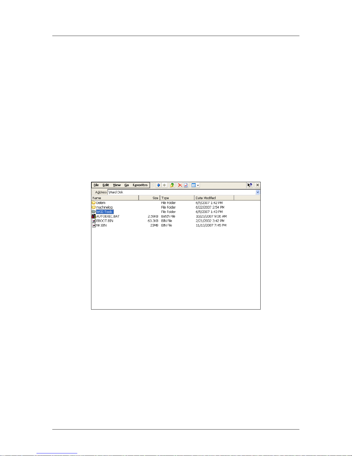
Delem
V0614, 2.23
2.4. Editing the autoexec.bat
The file ‘autoexec.bat’ is a standard file in the Windows system. Any command that can be
executed from the command prompt can also be put in this ‘batch file’. Whenever the control
is started or rebooted, the system will first look for the special batch file ‘autoexec.bat’. Any
command that is written down there will be executed by the system automatically.
Common tasks for such a file can be to copy files to or from the flash memory. In the
standard file, one task is implemented: activate the Delem application. Other tasks can be
added if required.
To enable fast editing of this batch file, the control is equipped with the application Notepad, it
is located in the directory \Hard Disk\WCE-Tools. To edit the Autoexec.bat, start this
application.
Note:
Upon delivery of the control or after installation of new software, the file ‘autoexec.bat’ may
be set to ‘read-only’ for safety purposes. If that is the case, it cannot be edited. See section
2.3 on how to change file properties.
Figure 2.e
When the file has been opened, the following screen appears:
Page 51
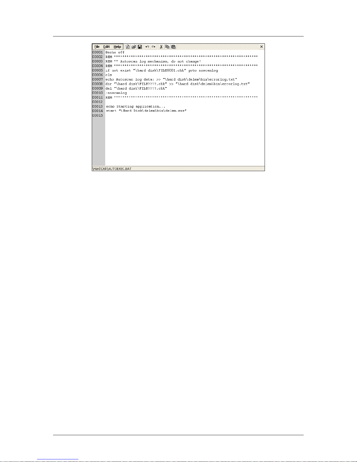
Delem
V0614, 2.24
Figure 2.f
The file can now be edited. When finished, click on ‘Save’ to save the changes and close the
file. If you wish to abort the operation, click on ‘cancel’. The file will be closed and the
changes will be lost.
Lines in the file that start with ‘REM’ are considered as comment.
In the beginning of the file, the ‘if’ instruction checks if the Delem application has a KO-table
to work with. If such a KO-table is present, the subsequent instruction is skipped.
At the end of the file, the Delem application is started through the instruction:
start “\Hard disk\delem\bin\delem.exe”
This will ensure that the control automatically activates the Delem application at start-up of
the control.
Page 52
Delem
V0614, 2.25
2.5. Control Rescue procedure
The Rescue procedure for the Delem control is meant to re-install all original software on the
control. It is meant as a last resort, when other attempts to ‘cure’ the control have failed
and/or the control does no longer boot from the internal flash memory).
When this procedure is carried out, all existing data on the hard drive is erased: products,
tools, etc. This also means that license codes for control options are erased. These options
can be requested again with the original vouchers.
This procedure can only be successful when all hardware is still functional.
Following two situations have different approaches for the rescue operation:
- What to do when the DA-52s application does not start?
(The control boots and shows the desktop)
- What to do when the Control does not boot?
(The display shows a black screen with a Delem logo)
What to do when the DA-52s application does not start?
(The control boots and shows the desktop)
Preparation
To perform the procedure on the control the following is necessary:
- USB-stick with a backup or update software
Procedure
1. Switch off the power of the control
2. Press and hold the
- key
3. Switch on the power
The following message will appear:
4. Enter the access code: 25789 followed by the enter-key
The following message will appear:
5. Select option: 1
6. Follow the instructions on the screen (here you need the USB-stick with backup- or
update software).
Page 53
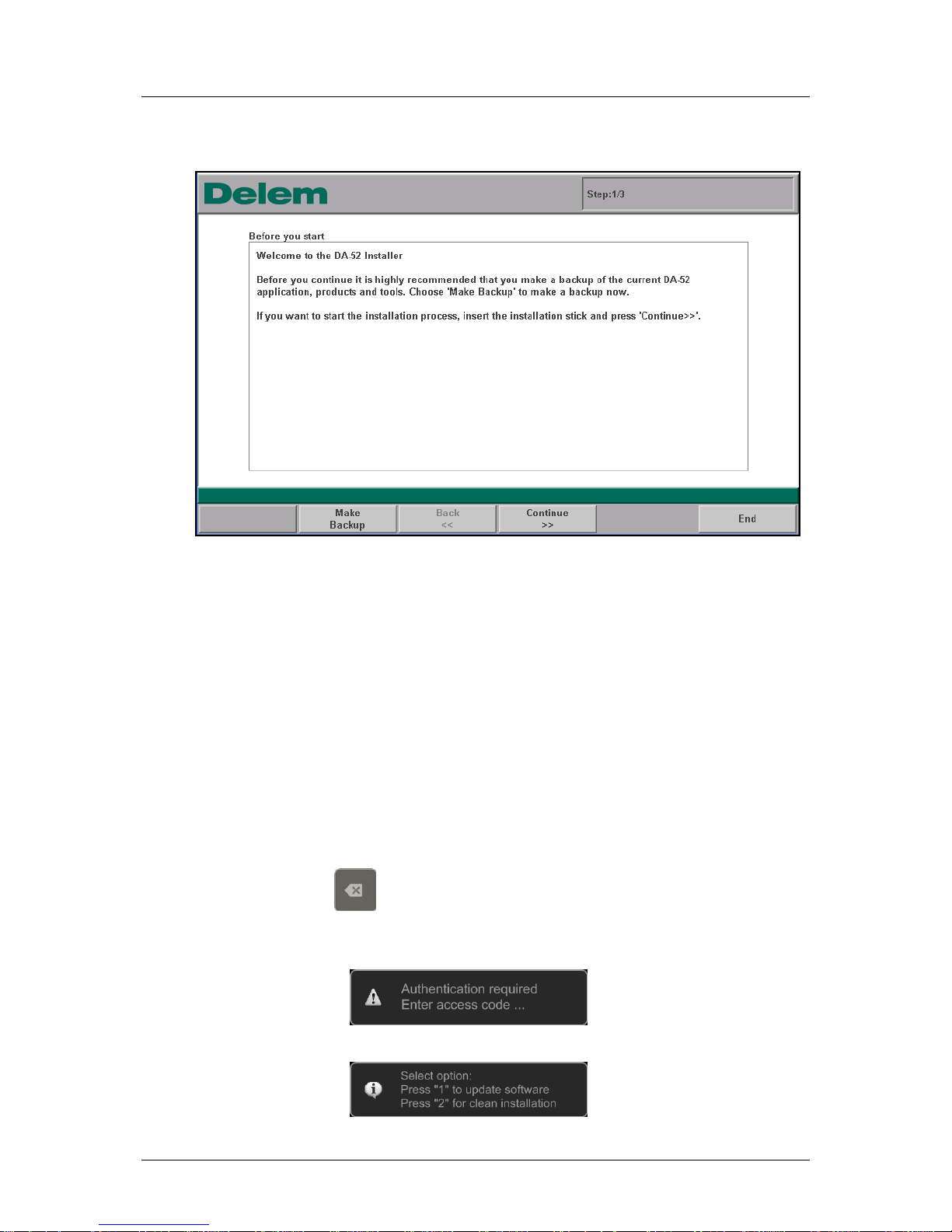
Delem
V0614, 2.26
7. The control reboots and starts with the updater:
Figure 2.g
8. Follow the update procedure as described in paragraph 1.2.1, Update procedure.
What to do when the Control does not boot?
(The display shows a black screen with a Delem logo)
Preparation
To perform the procedure on the control the following is necessary:
- empty USB-stick (to create a Rescue-stick if required)
- USB-stick with a backup or update software
Start Procedure:
1. Switch off the power
2. Press and hold the
- key
3. Switch on the power
The following message will appear:
4. Enter access code: 25789 followed by the enter-key
The following message will appear:
Page 54
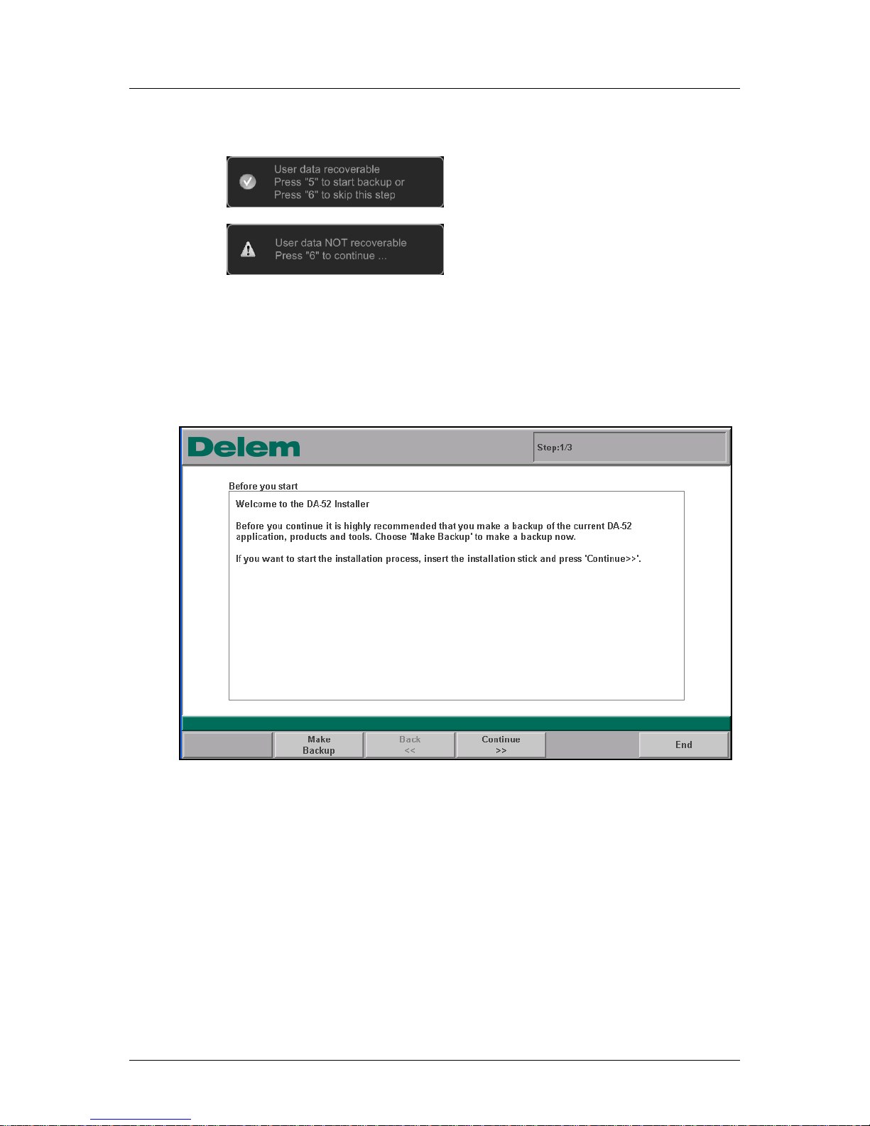
Delem
V0614, 2.27
5. Select option: 2
6. Recover files from the control.
One of following screens will show:
a.
Follow the instruction on the screen (for backup use the empty USB-stick).
b.
Follow instruction on the screen.
7. After the backup the kernel will be installed, follow the instructions on the screen.
(Do not use the USB-stick with recovered data. Use the USB-stick with a backup- or
the update-software).
8. The control reboots and starts with the updater:
Figure 2.h
9. Follow the same update procedure as described in paragraph 1.2.1, Update
procedure.
Page 55
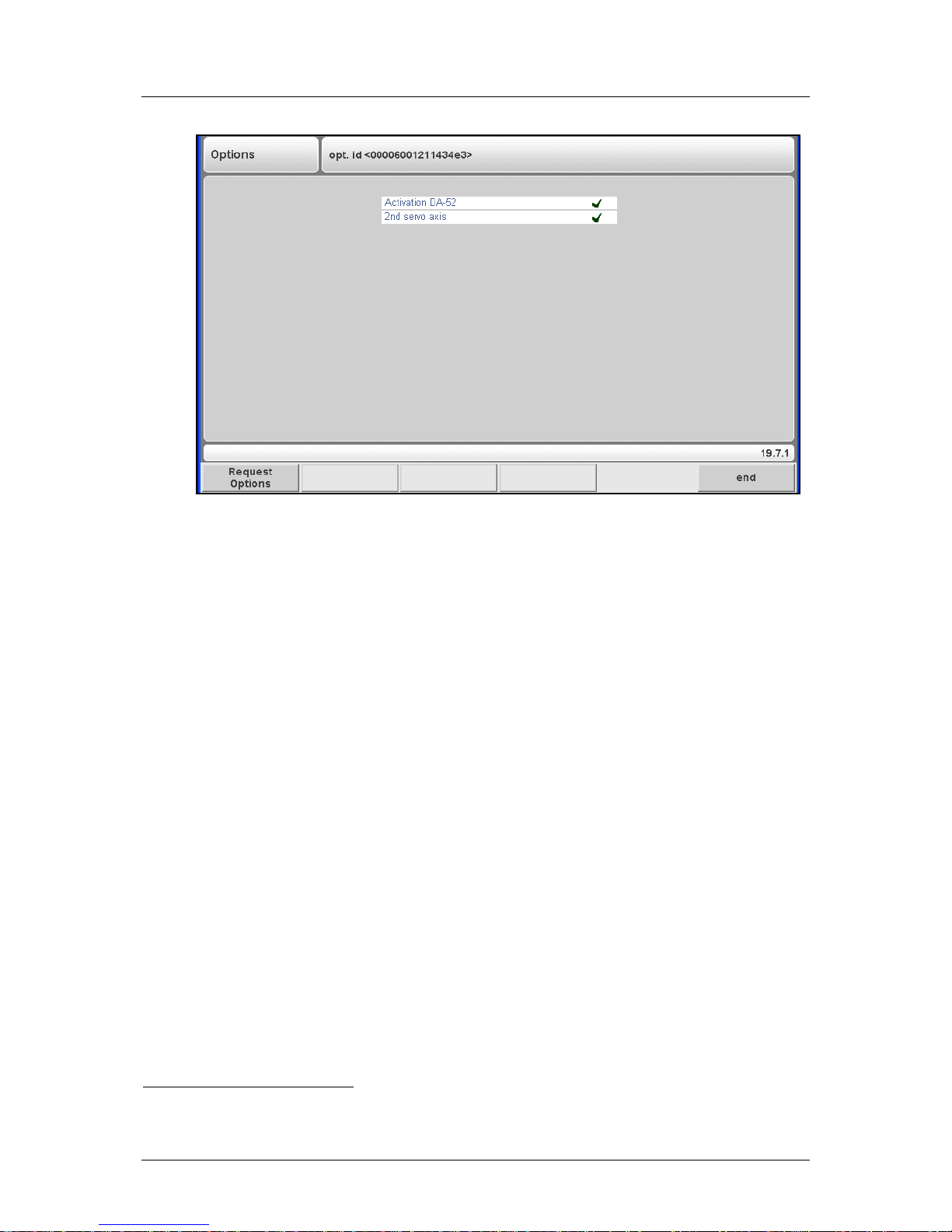
Delem
V0614, 2.28
10. When installation is finished the control starts with the Voucher application.
Figure 2.i
11. Plug in the USB-stick with a backup- or the stick with the recovered-data)
12.
1
Select "Import Certificate" and find the license files on the USB-stick.
Find it in: \\Delem\Licences\
13. Optionally follow the same procedure for the X2 option.
14. Via Machine Parameters you can now choose to update the control with the rescue
stick. This gets the control to as close as possible to its last status.
1
If there is no backup available and the rescu e di d not manage to salvage the license files you need to get the voucher sheet
that was sent with the control and follow the procedure as described in paragraph 1.3,
Option installation.
Page 56
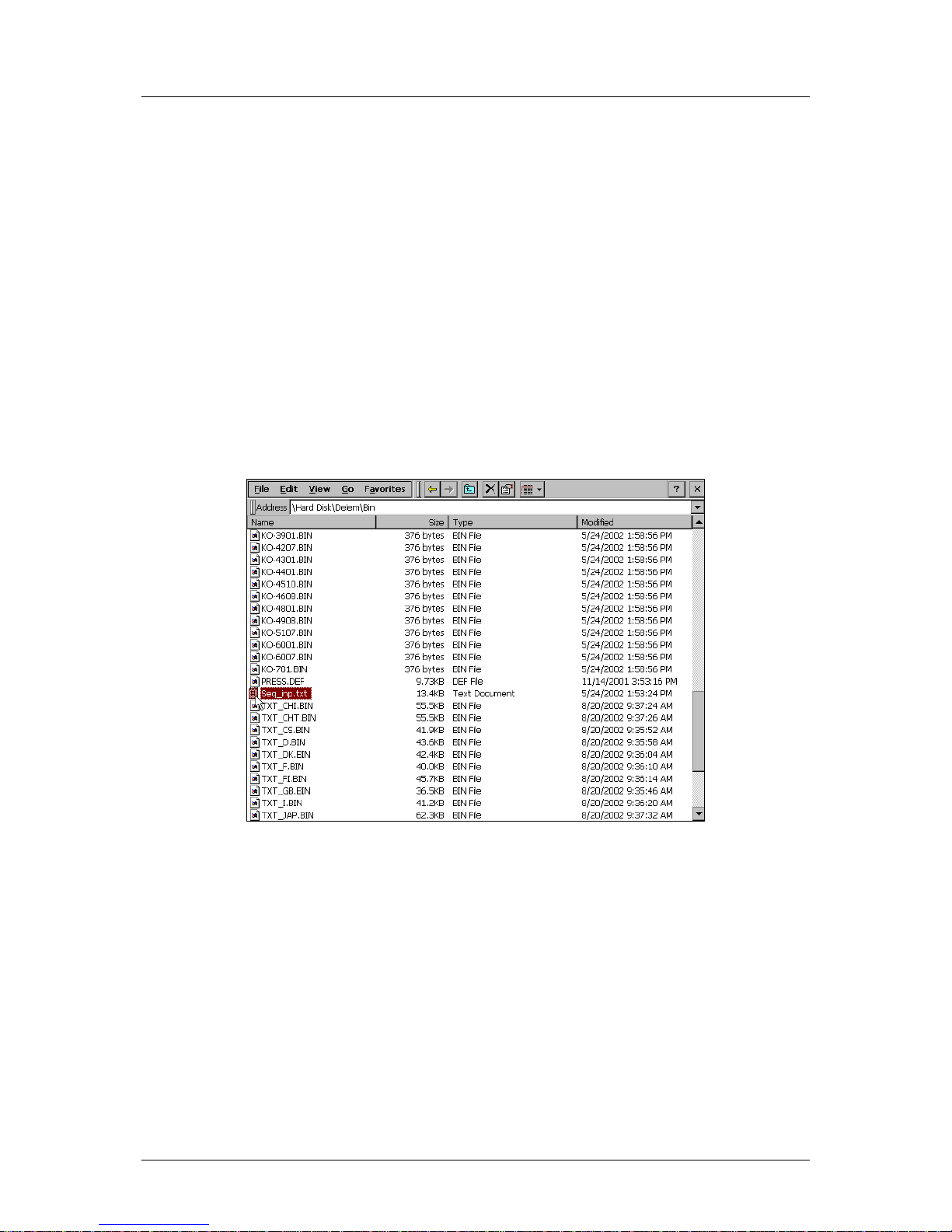
Delem
V0614, 2.29
2.6. Sequencer adjustment
The sequencer is the built-in PLC function of the Delem system. The text file with sequencer
code is stored on the hard disk of the control, in the file seq_inp.txt. This file can be edited
with the application Notepad that is built-in on the control. An alternative could be to copy the
file to a USB disk and edit the file from a PC. After that, the file can be copied back to the
control.
The procedure to open and modify the sequencer runs as follows:
• go to the Windows environment;
• activate the Windows Explorer;
• go to the subdirectory \Hard Disk\Delem\Bin: a large list of files is shown;
• search the file ‘seq_inp.txt’;
• replace this file with your own sequencer program or modify this file. It is recommended
to keep a backup of the standard file, in case of programming errors;
• when sequencer modifications are completed, save the text file and close it.
Figure 2.j
• Go to the start menu and choose ‘Reboot’. The control will restart.
Page 57
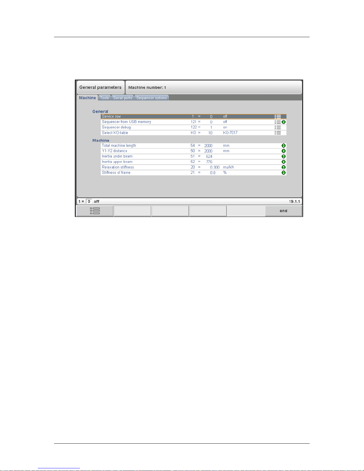
Delem
V0614, 2.30
To simplify testing during the development of a sequencer modification the sequencer can be
loaded from a USB-stick without having to copy it to the control.
Figure 2.k
In the machine parameters the parameter ‘Sequencer from USB memory’ can be switched
on. When the sequencer is final, the softkey ‘Install Sequencer’ can be used to copy the
sequencer files seq_inp.TXT and *.DEF to the sequencer directory in the control. After
installing the new sequencer the parameter ‘Sequencer from USB memory’ can be switched
off again.
For a description of sequencer programming we refer to the Delem sequencer programming
language manual [2].
Page 58
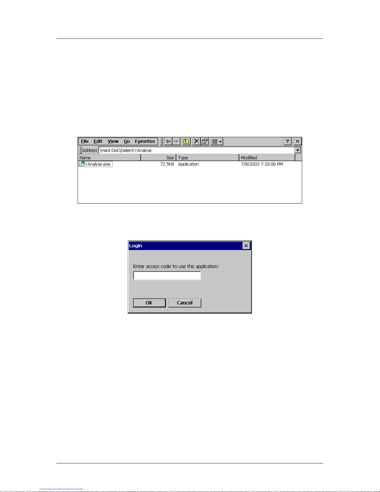
Delem
V0614, 2.31
2.7. Analysis program
The control is equipped with a program for analysis of a pressbrake cycle. This analysis
program can run parallel to the DA application.
The working principle is as follows. During one bend cycle, the program records the values of
a number of analog and digital I/O signals. All this data is immediately stored in a file on the
control disk and can be represented graphically.
The program is called YAnalyse.exe and is located in the directory:
\Hard Disk\Delem\YAnalyse.
Figure 2.l
Upon start-up, the program will first prompt for an access code:
Figure 2.m
Here you must enter a ‘level 2’ code, which is also used to modify all Delem machine
parameters in the DA application. The default access code here is 32157.
With the ‘new’ command, a new file is created. Type a name you wish to give to the file. At
the beginning this file is empty, it will be filled with cycle information as soon as a cycle is
recorded by the analysis program.
Each cycle is stored in a separate file. To this end, the name of each file consists of the name
you entered, followed by a number. Every time a cycle is recorded, the number in the
filename is incremented by 1. So it is possible to record all bends of a product, each bend is
stored in a file. Each bend can be analysed afterwards. With the buttons ‘previous’ and ‘next’
it is possible to browse through the collection of bends.
Page 59
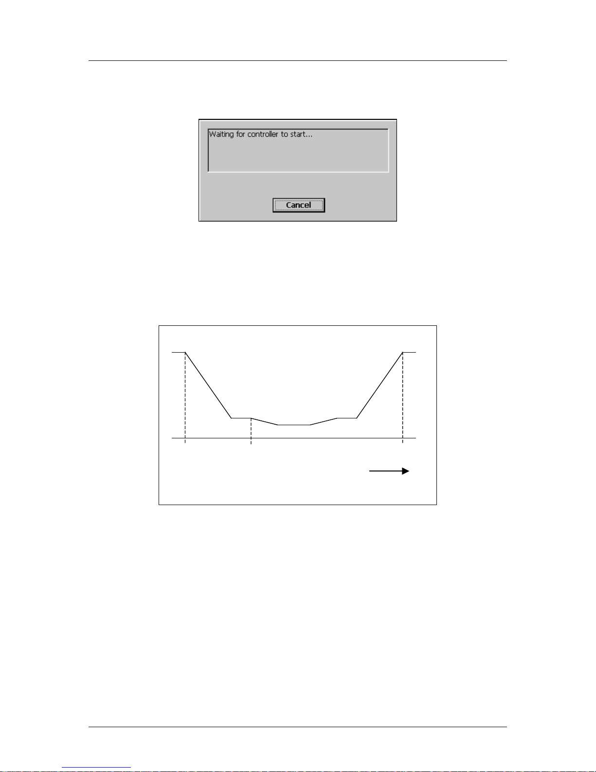
Delem
V0614, 2.32
To record a bend cycle, use the ‘start measure’ command. The program will show the
following dialog:
Figure 2.n
This means the analysis tool is now waiting for a bend cycle to be executed. Now switch to
the DA application and execute a bend cycle in the normal way. The analysis program
actually starts recording when a fast closing or a pressing command is activated. The
program will continue to record until an UDP (upper dead point) signal is generated,
indicating that the bend cycle is finished.
Closing
Pressing
t
UDP
Figure 2.o
When the bend cycle is finished, switch back to the analysis program. On the screen you can
see a graphic of the beam position as a function of the cycle time.
As already explained, each recorded cycle is stored in a file. So it is also possible to open a
previously recorded file for further analysis.
Page 60
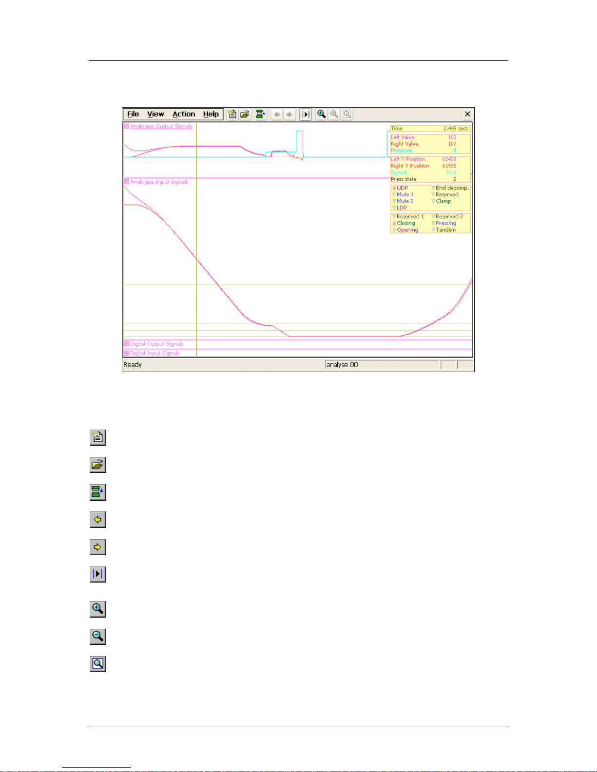
Delem
V0614, 2.33
A typical analysis screen of one cycle could look as follows:
Figure 2.p
The toolbar at the top of the screen has the following commands:
new
create a new file for recording of cycles
open
open an existing analysis file
start measure
record a pressbrake cycle
previous
jump to previous recording
next
jump to next recording
fix cursor
freeze the cursor on the current position and move with a
second cursor to another moment in the cycle, for
comparison purposes
zoom in
increase magnification, to study specific signals more closely
zoom out
decrease magnification, to get a more global view
reset
reset view to initial state, with smallest magnification
Page 61

Delem
V0614, 2.34
The signals are divided in four groups. Each group can be opened or closed, in order to
examine one group more closely. The value of all recorded signals is shown in the text box,
which can be placed left or right with the <tab> key.
The following groups are shown:
• analog output signals
• analog input signals
• digital output signals
• digital input signals
For the meaning of all signals we refer to the Delem machine parameter manual, where all
signals are described in detail.
Remarks:
• If cycle files must be kept for further analysis, it is recommended to store them in nonvolatile memory. For instance, when the ‘new’ command is first used to create a file, the
directory \Temp is offered. This directory is lost when the control is switched off! To keep
the files on a permanent medium, store the cycle files on the control hard disk or a USB
disk. See also section 2.2 for more information about directories.
• The cycle files are automatically given the extension ‘.frd’ and can be read on any control
that is equipped with this analysis software. They can also be sent to Delem if more
support is necessary.
Page 62

Delem
V0614, 3.1
Part III - The diagnostic progr a m
To be able to test a DA-52s control, it has been equipped with a diagnostic program. With the
test functions of the diagnostic program the service engineer can test the control itself and
the communications to externally connected system components.
Page 63

Delem
V0614, 3.2
1. General remarks
1.1. Valve outputs
Before starting the diagnostic program it is required to check if the hydraulic pump of the
pressbrake is not running. This is because during the diagnostic operation of the control no
regulation of the pressbeam is performed.
With the diagnostic program you have to be very careful because the proportional valves can
be deflected. The height-retaining valves have to be in the closed position in order to prevent
the top beam coming down. It is good practice to place the top beam in its lowest position
befor e starting the diag nostic program.
1.2. Components check
In the description of the tests it is indicated which component(s) is(are) responsible for
correct functioning of that particular part.
See for exploded view drawing with all internal cables and cards of the DA-52s controls the
included diagrams at the end of part I.
Page 64
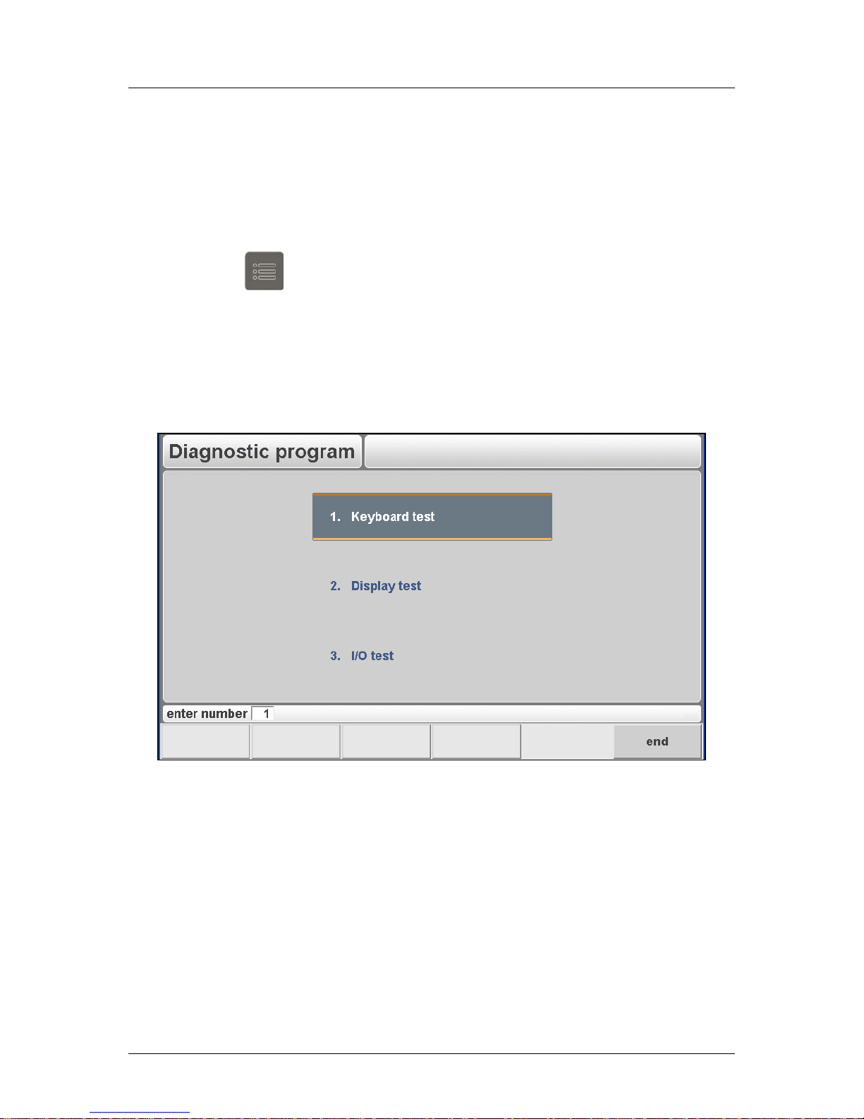
Delem
V0614, 3.3
2. Test-menu
2.1. Start diagnostic mode
To open the diagnostic program:
• press the key
to go to the program constants
• on the first parameter, enter the access code 741
2.2. The menu
When the diagnostic program has been started the screen shows the menu as indicated in
figure 2.a (example of diagnostic main menu).
Figure 2.a
Diagnostic Options:
1
Keys
Testing all the frontpanel keys. See Chapter 3.
2
Display test
Testing the screen.
3
I/O test
Testing the I/O.
To end the diagnostic program the power supply to the control can be switched off and then
on again to enter the normal operation menu.
It is also possible to leave the diagnostic program with the ‘END’-key. The Delem application
will restart.
Page 65
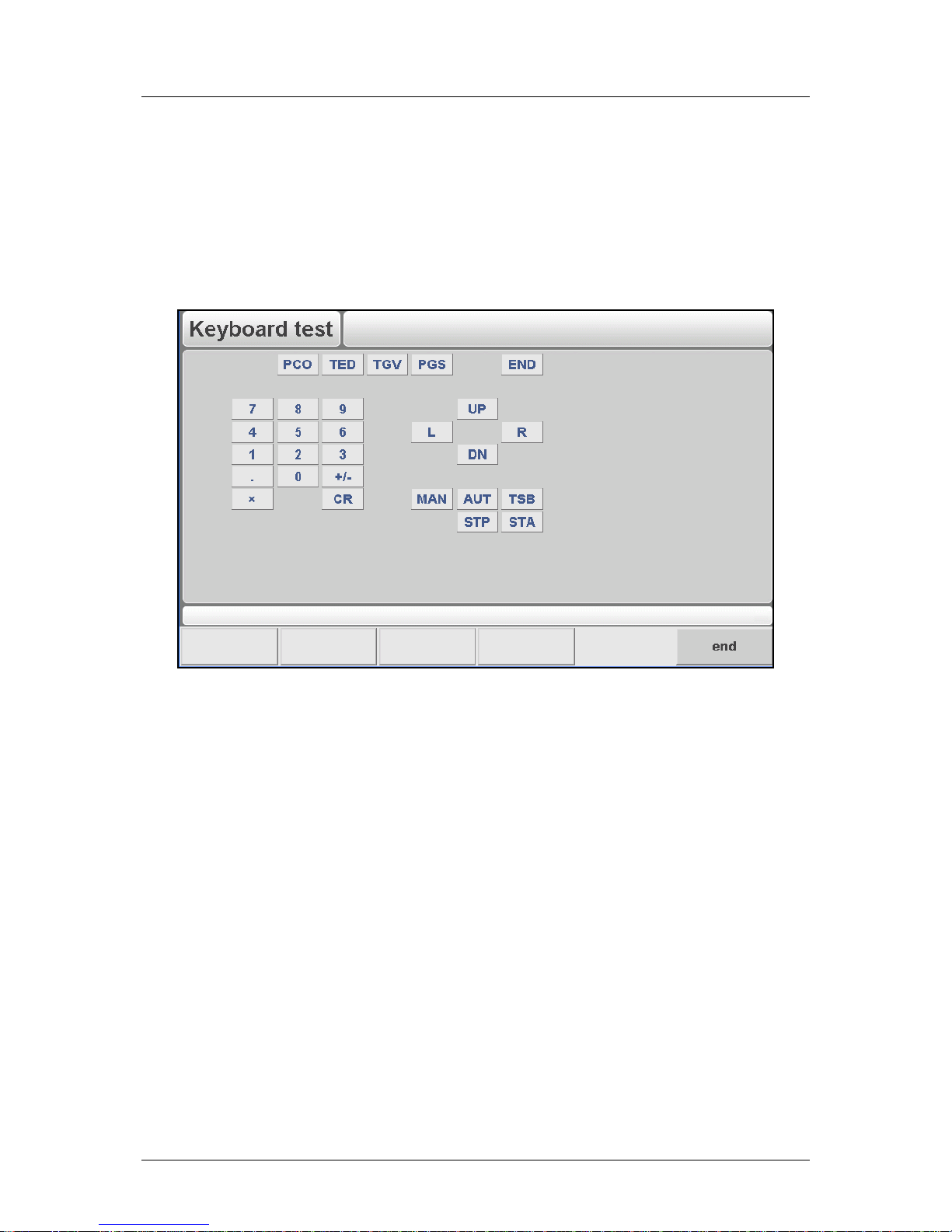
Delem
V0614, 3.4
3. Key test
Function
This test is meant to check the functioning of all the frontpanel keys.
Description
First you see a matrix with all keys, like in figure 3.a.
Figure 3.a
• Each t im e you press a key on the front, the corresponding position on the screen will
give a unique indication. Entering the key test will result that all LED’s in the mode keys
and start/stop keys on the frontpanel automatically will light-up (and stay on during the
diagnostic mode). You can test these mode keys and the start/stop keys by pushing the
corresponding keys. The result is that the corresponding key on the screen will light up.
• The reading of the movement keys is tested by a counter. When you press the key ‘+’,
it must result in an increasing value on the screen (up counting). When you press the
key ‘-‘, it must result in a decreasing value on the screen (down counting).
• The key lock status is displayed and can also be tested by turning the key from the ON
to the OFF position. In the ‘keylock is off’ position the program data cannot be changed.
Failure
A failure (a key is not operative) can be caused by the frontpanel electronics, the front cable
or the front interface on the mainboard.
End
Pushing the softkey ‘END’ finishes this test.
Page 66
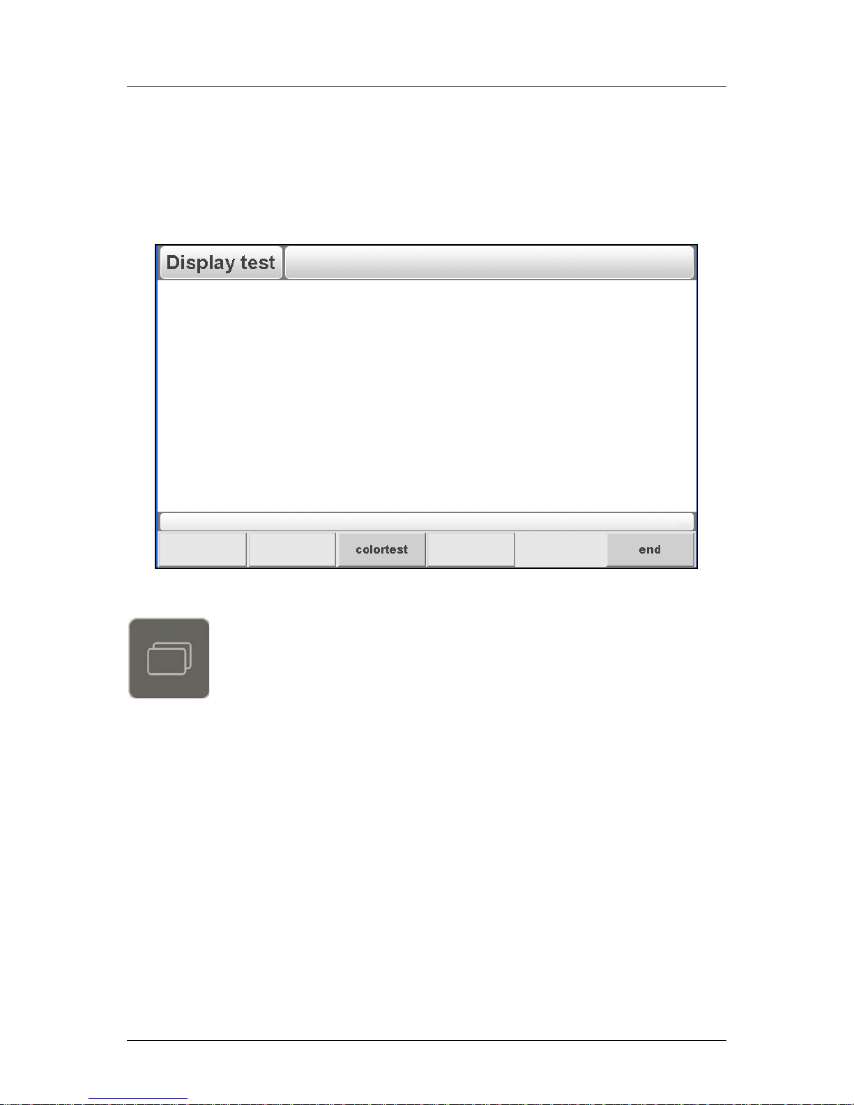
Delem
V0614, 3.5
4. Screen test
Function
The screen of the control can be tested with 2 different test programs, to be selected with the
front panel keys.
Figure 4.a
colortest
Check the display of colours on the screen.
Page 67
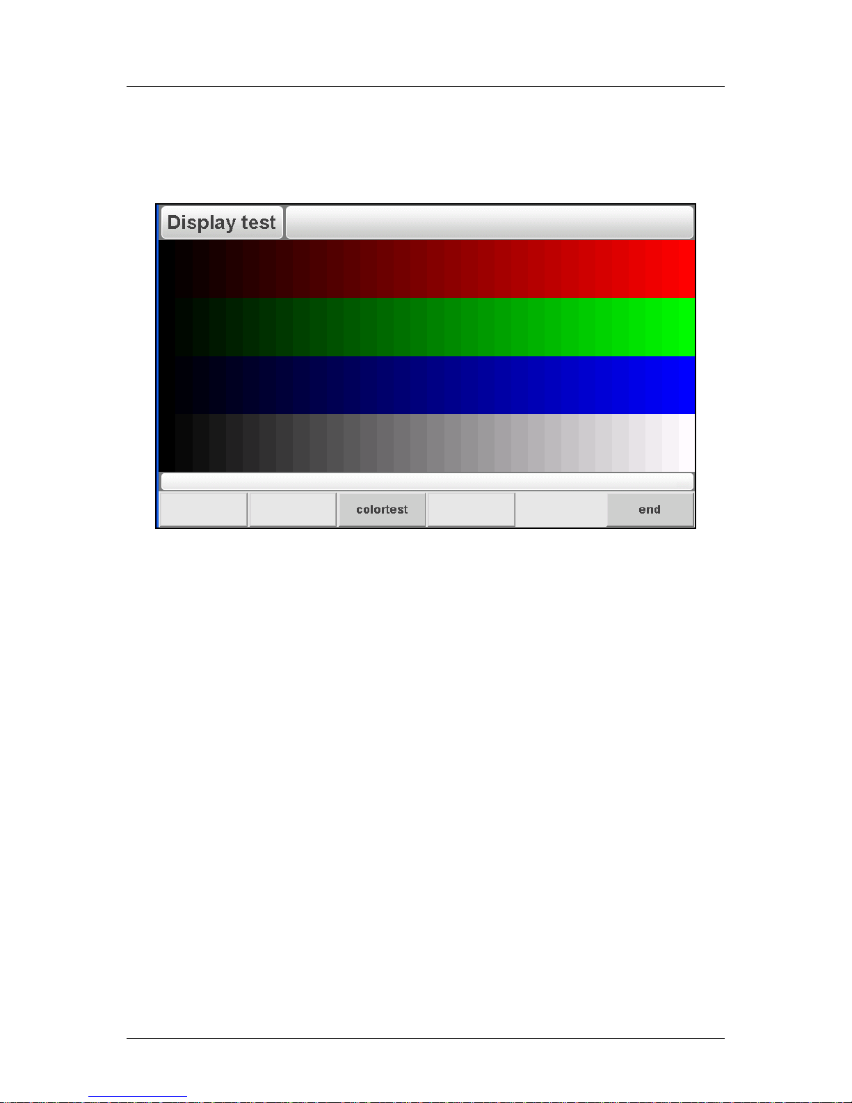
Delem
V0614, 3.6
Colortest
To get a good idea about the colour setting and correct functioning of the colour screen you
will see a number of vertical bars. It is important that the 3 main colours are available (red,
green and blue).
Figure 4.b
End
To end the monitor-test program press softkey END.
Page 68
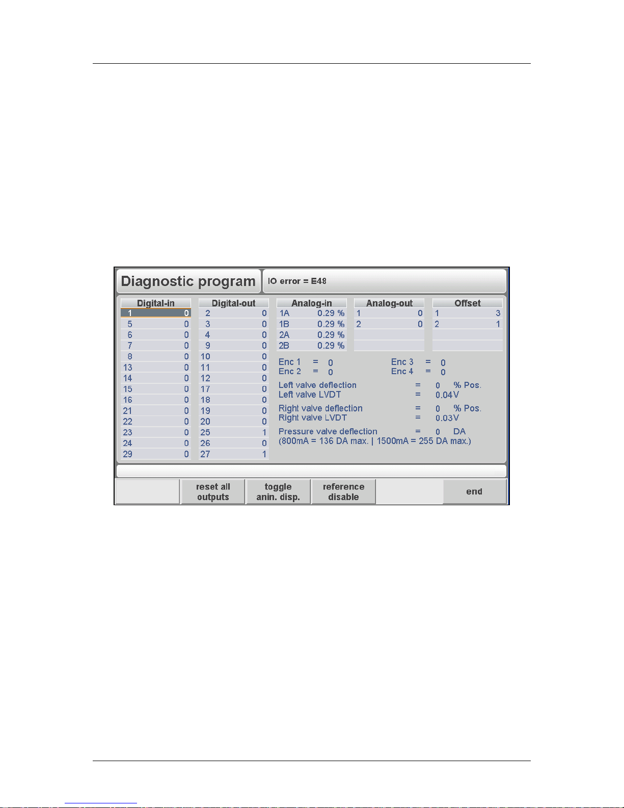
Delem
V0614, 3.7
5. I/O test
5.1. Test screen
Description
In this screen the system I/O of the control can be tested and monitored. Analog and digital
outputs can be set high and low with keys on the front panel.
The read-out of analog inputs and the encoders is continuously. When a reference pulse of
the linear scales is received in the electronics, the corresponding measured value will shortly
be highlighted in inverse colour. (Only when the concerning reference check has been
enabled with the function key).
Figure 5.a
Reset all outputs
Reset all digital outputs of the control (set to zero).
Toggle anin display
Function to switch value of analogue input voltage between ADpoints and a percentage.
reference disable
Testing the encoder counting of the X-axis or any Auxiliary axis.
Toggle function between enabled and disabled. Default disabled. In
the disabled situation you can test the count direction. In the enabled
situation you can test whether the reference pulse is received (once
per encoder rotation). ENC in the upper row.
Cursor left-right
Change from Digital-out to Analogue-out.
Enter
Press enter to toggle Digital-out between 0 and 1.
Manual movement
keys
To change the value of the Analogue-out parameters.
• Testing the analogue output
Page 69

Delem
V0614, 3.8
With this option the analogue outputs can be tested. These signals are used for the control
amplifiers of the X-axis and auxiliary axes. The output voltage varies between -10V and
+10V. The value (+/- 255 DA-points) can be altered with the manual movement keys.
The string ‘OUTAN1’ and ‘OUTAN2’ refer to the outputs in the analog A connector. See the
schematic 8063-104 for the location of these outputs.
• Output test and adjustment procedure
1. Set both the OUTAN1 and the OFFAN1 to zero by using the manual movement keys.
Meaning that you should measure 0V at the output and the connected axis should not
move.
2. If the measured output voltage is not zero, you must set the output voltage to zero with
the OFFAN1 adjustment.
3. With the zero output voltage the motor should not move. A possible movement can be
corrected with the offset adjustment of the concerning motor drive.
4. For further fine-tuning you can adjust the value of the OFFAN1 again.
• Testing the digital inputs
In case a digital input is active, the indication on the screen will be ‘1’, otherwise the
indication is ‘0’. When you connect a DC-voltage of 24V at the selected input, the signal
indication of the corresponding input on the screen must become ‘1’.
If none of the inputs is working, please check the common input connection and the general
+24V.
• Testing the digital outputs
Move with the cursor keys to a digital output number, Press ‘1’ to activate the output. In case
you press ‘0’ the output is deactivated.
• Testing the analogue inputs
The value on the screen is the read-out of the voltage in DA-points which is offered to the
analogue input. By varying the voltage the read-out should vary likewise.
Failure
External electronics, DA-52s or the wiring (including connectors).
Page 70

Delem
V0614, 3.9
5.2. Testing the valve deflection
Function
With this test the hydraulic-valve drive circuitry can be tested. Also the hydraulic pressure can
be tested. To perform this test all the valves must be connected correctly.
Description
Via the cursor keys or the function keys S1, S2 and S3 you can select the required valve.
The test procedure for valve deflection depends on the type of valves that is installed. On the
following two pages two different procedures are described. The first procedure is for
Hoerbiger valves, which are connected directly to the DA-52s. The second procedure must
be followed when external valve amplifiers are used to control the valves.
Page 71
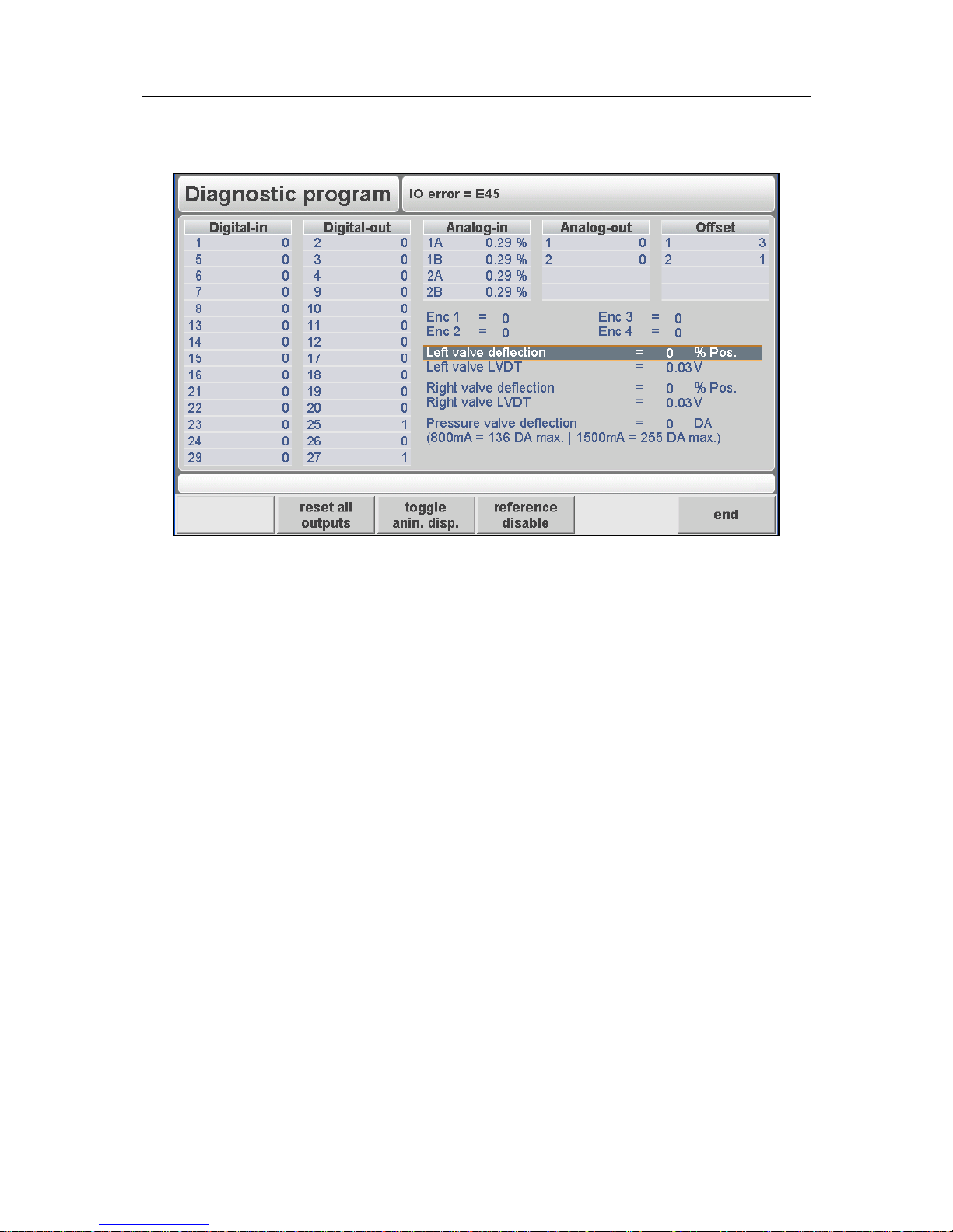
Delem
V0614, 3.10
• Test procedure (Hoerbiger valves)
Figure 5.b
1. Move cursor to ‘Left valve deflection’.
2. Set ‘Left valve deflection’ at +10% by using the manual movement keys. To avoid
possible influence of hysteresis it is recommended to go first to +100% and than to the
required +10%.
3. Move cursor to ‘Left valve LVDT’. This is the read out of the left proportional valve. The
value should be 8.0V. If not, then adjust this value with the manual movement keys.
4. Move cursor to ‘Left valve deflection’ again.
5. Set ‘Left valve deflection’ at -10% by using the manual movement keys. To avoid possible
influence of hysteresis it is recommended to go first to -100% and than to the required 10%.
6. Move cursor to ‘Left valve LVDT’. This is the read out of the left proportional valve. The
value should now be 7.15V. If not, then adjust this value with the manual movement keys.
7. Repeat this procedure (step 1 through step 6) for the right proportional valve.
The pressure valve can be tested by measuring the current through the pressure valve at
several DA-points. With the manual movement keys you can regulate the valve deflection in
DA-points (0 DA = 0 mA). The current can be measured with an ammeter in series with the
pressure valve.
Note
The maximum allowed DA-points per installed current type of the pressure valve.
Failure
External electronics, wiring, valves or DA-52s.
End
Press the END-key to finish this test.
Page 72
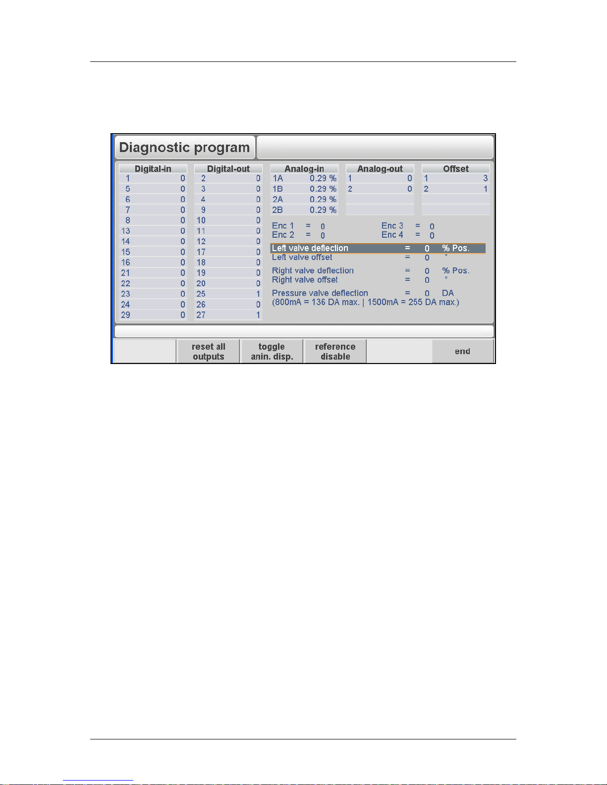
Delem
V0614, 3.11
• Test procedure (External valve amplifier)
In this menu the analogue output for valve control is tested.
Figure 5.c
1. Move the cursor to the field ‘left valve’.
2. Use th e manual movement keys to put both the output value and the offset value at zero.
The voltage at the output should now also be zero.
3. If the measured output voltage is not zero, you must set the output voltage to zero with
the offset adjustment.
4. Repeat these steps for the other valve.
5. Further fine-tuning can be done through the calibration procedure as described in the
Delem machine parameter manual at parameter 15, ‘Calibrate valves’. That procedure is
designed especially for external valve amplifiers.
Failure
External electronics, wiring, valves or DA-52s.
End
Press the END-key to finish this test.
Page 73

Delem
V0614, A.1
Appendix A - Reference list
[1] Delem machine parameters
[2] Delem Sequencer Programming Language
[3] Reference manual for operation of DA-52s
 Loading...