

DEK Remote Barcode Reader 1D, Remote Barcode Reader 2D, Handheld Barcode Reader 1D, Handheld Barcode Reader 2D Technical Reference Manual
Page 1
BARCODE READER
OVERVIEW
Chapter Issue 3 Jan 08 Technical Reference Manual 26.1
CHAPTER 26 BARCODE READER
OVERVIEW
WARNING
RADIATION. RISK OF INJURY TO THE EYES DUE TO LASER LIGHT BEING
PRESENT IN THE VICINITY OF THE LABEL. DO NOT LOOK AT THE LIGHT
SOURCE OR REFLECTIONS FROM A SURFACE.
There are four types of barcode readers that may be fitted to the machine:
• Remote Barcode Reader 1D
• Remote Barcode Reader 2D
• Handheld Barcode Reader 1D
• Handheld Barcode Reader 2D
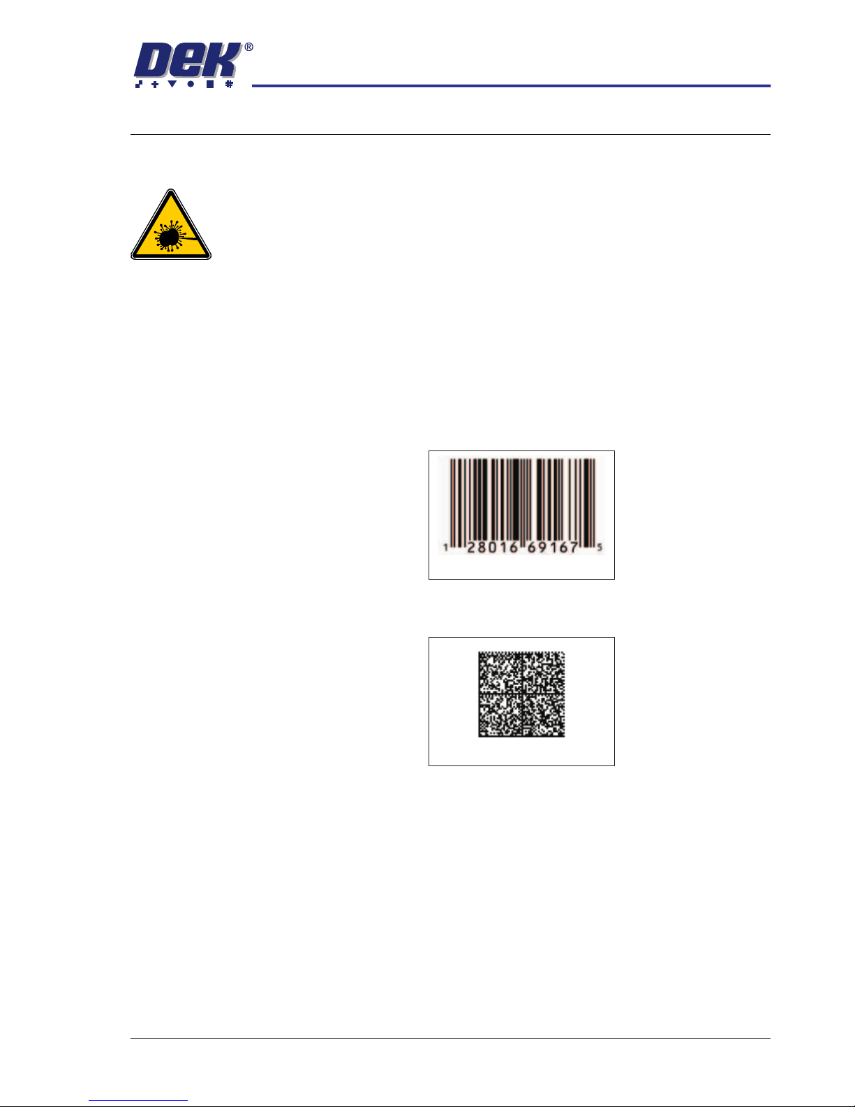
1D or one dimensional barcodes are the most common barcodes consisting of
a single row of different width bars.
2D or two dimensional barcodes consist of square modules constructed in a
matrix that may be square or rectangular.
NOTE
There are many different formats of barcodes and the above are single exam-
ples to demonstrate the difference between 1D and 2D barcodes.
Example of a 1D Barcode
Example of a 2D Barcode
Page 2
BARCODE READER
OVERVIEW
26.2 Technical Reference Manual Chapter Issue 3 Jan 08
Remote Barcode
Reader
The remote barcode reader is normally located on the input conveyor to the
machine and reads the barcode of the incoming product board.
The remote barcode reader provides GEM and SPC of the product barcode
before the product is passed to the printer. Use of the reader enables the host
program to decide on the action to be taken for this product and provides a
method for SPC to log product details for tracking.
The remote barcode reader also provides information to the Verification and
Traceability software option.
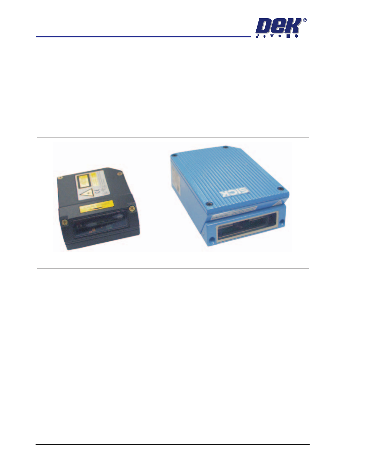
Different types of remote barcode readers may be used, a typical example is
shown below:
During the board/product transfer cycle, with the remote barcode option enabled, the trigger barcode scan sensor detects the board on the conveyor and
triggers the remote barcode reader to read the barcode, before the board is
passed to the printer.
Handheld Barcode
Reader
The primary function of the handheld barcode reader is to scan consumables
and user information for the Verification and Traceability software. The consumables scanned include:
•Screen
• Print Material
• Solvent
• Cleaner Paper
• Vortex Cassette
The handheld barcode reader may also be used to scan the first board of a
batch that is to be checked by the remote barcode reader during a print run.
1D Remote Barcode Reader
2D Remote Barcode Reader
Page 3

BARCODE READER
OVERVIEW
Chapter Issue 3 Jan 08 Technical Reference Manual 26.3
Different types of handheld barcode readers may be used, a typical example is
shown below:
NOTE
The 2D handheld barcode reader supplied by DEK requires an additional 12V
supply to power the reader. The 1D handheld barcode reader supplied by DEK
is powered from the USB port.
1D Handheld Barcode Reader
2D Barcode ReaderHandheld
Page 4

BARCODE READER
ELECTRICAL SCHEMATIC
26.4 Technical Reference Manual Chapter Issue 3 Jan 08
ELECTRICAL SCHEMATIC
01
03
M37 Power Supply
+12V
+12V
0V
0V
8PL104
M37PL13
01
03
02
03
01
01
04
03
03
02
01
04
03
02
01
04
03
02
01
04
03
02
01
04
Machine PC
Handheld
Barcode
Reader
6PL23
6PL22
01
03
02
07
04
05
13
25
NC
NC
10
18
09
19
01
02
03
01
02
03
04
Chassis
RTS232
TX232
RX232
CTS232
Signal GND
VS
GND
PS+
VS
PS-
Trigger
Barcode
Scan
6SE07
+12V
0V
Signal
Alarm
Remote Barcode Reader
3PL34
4PL01
4PL37
4PL05
8SK145
03
03
02
02
01
01
04
04
06
09
07
08
05
6PL17
01
03
02
07
04
05
13
25
3PL20
USB to
RS232
Converter
3PL57
USB8
USB1
NOTE
The USB to RS232 Converter
is moulded into the 9 Pin D type
connector hood.
4 Port
USB Hub
Connector
Moulding
M37PL14
(2D handheld barcode reader only)
Page 5

BARCODE READER
REPLACEMENT PROCEDURES
Chapter Issue 3 Jan 08 Technical Reference Manual 26.5
REPLACEMENT PROCEDURES
Fitting the Remote
Barcode Reader
1. Select Shut Down and switch the mains isolator to OFF.
2. Fit the remote barcode reader to the upline conveyor ensuring that the
reader is in a position to read the barcode on the product board during
transit.
3. If required, fit the trigger sensor just forward (upline) of the reader.
NOTE
The leading edge of the incoming board triggers the remote barcode reader
to activate enabling it to read the barcode on the board.
4. Remove the rear panel to gain access to the PC.
5. Route the cable from the conveyor, under the Dek machine exiting at the
rear of the machine.
6. Connect the USB plug to USB8 on the PC.
7. Connect the power lead M37PL13 to M37SK13 on the rear of the M37
Power Supply Enclosure.
8. Refit the rear panel ensuring that the cable is not trapped.
9. Power up the machine.
10. Select Maintenance.
11. Select Machine Setup.
12. Select Barcodes.
Shut Down
PC Enclosure Rear Panel
I
O
USB8
Maintenance
Machine
Setup
Barcodes
Page 6

BARCODE READER
REPLACEMENT PROCEDURES
26.6 Technical Reference Manual Chapter Issue 3 Jan 08
13. Select Remote Barcode HW.
14. Select Fitted.
15. Select Accept.
16. Select Start Character.
17. Set the start character for the barcode.
18. Select Accept.
19. Select Name Length.
20. Set the name length for the barcode.
21. Select Accept.
NOTE
The barcode setup is shown in code format. The code format for a barcode
of length 14 starting at character 4 would be:
###PPPPPPPPPPPPPP###
22. Select Back.
23. Select Back.
24. Select Back.
25. Use the documentation supplied with the reader to setup the Remote
Barcode Reader for the product to be used.
Remote Barcode HW
Not Fitted
Fitted
Accept
Start Character
1
Accept
Name Length
32
Accept
Back
Back
Back
Page 7

BARCODE READER
REPLACEMENT PROCEDURES
Chapter Issue 3 Jan 08 Technical Reference Manual 26.7
Fitting the
Handheld Barcode
Reader
1. Select Shut Down and switch the mains isolator to OFF.
2. Gain access to the 4 port USB hub behind the front panel.
3. Connect the handheld barcode reader to the spare USB port on the hub.
4. If a 2D handheld barcode reader is being used, connect the dc power
connector (located near the 4 port USB hub) to the moulded connector on
the cable of the handheld barcode reader.
5. Refit the front cover ensuring that the cable is routed between the MMI
monitor bracket and the front cover.
6. Power up the machine.
7. Select Maintenance.
8. Select Machine Setup.
9. Select Barcodes.
10. Select Handheld Barcode HW.
Shut Down
USB Connector dc Connector
Maintenance
Machine
Setup
Barcodes
Handheld Barcode HW
Not Fitted
Page 8

BARCODE READER
REPLACEMENT PROCEDURES
26.8 Technical Reference Manual Chapter Issue 3 Jan 08
11. Select Fitted.
12. Select Accept.
13. Select Start Character.
14. Set the start character for the barcode.
15. Select Accept.
16. Select Name Length.
17. Set the name length for the barcode.
18. Select Accept.
NOTE
The barcode setup is shown in code format. The code format for a barcode
of length 14 starting at character 4 would be:
###PPPPPPPPPPPPPP###
19. Select Back.
20. Select Back.
21. Select Back.
22. Use the documentation supplied with the reader to setup the language,
keyboard format and barcode symbology.
Fitted
Accept
Start Character
1
Accept
Name Length
32
Accept
Back
Back
Back
 Loading...