

DEK DXR-702 Installation Instructions Manual
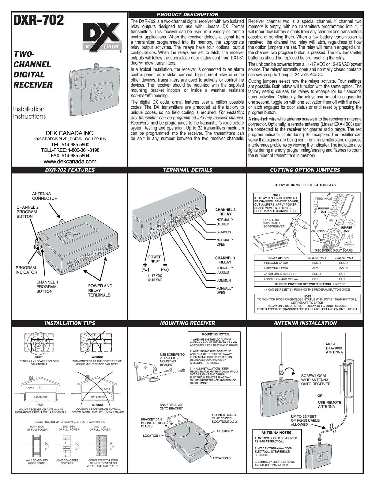
TERMINAL CONNECTIONS
N.O.
CO
M
N.C.
N.O.
COM
N.C.
N.O.
CO
M
N.C.
N.O.
CO
M
N.C.
N.O.
CO
M
N.C.
N.O.
CO
M
N.C.
N.O.
CO
M
N.C.
N.O.
CO
M
N.C.
N.O.
CO
M
N.C.
N.O.
CO
M
N.C.
N.O.
CO
M
N.C.
N.O.
CO
M
N.C.
DXR-702 TERMINALS DXR-702 TERMINALS
DXR-702 TERMINALS DXR-702 TERMINALS
DXR-702 TERMINALS
DXR-702 TERMINALS
ALARM PANEL CONNECTION WITH DOOR STATUS
LATCHING RELAY OPTION
ALARM
LOOP
1
N.C. OR N.O.
ALARM
LOOP 2
N.C. OR N.O.
NOTE:
LATCHING MODE
ALLOWS PANEL
TO SHOW DXT-31
DOOR STATUS
AUX.
POWER
ALARM
LOOP
N.C. OR N.O.
TROUBLE
LOOP
N.C. OR N.O.
AUX.
POWER
ALARM PANEL CONNECTION WITH LOW BATTERY REPORTING
LATCHING RELAY OPTION
NOTE:
CHANNEL 2 MUST
BE EMPTY TO
REPORT LOW
BATTERY
ALARM
LOOP
1
N.C. OR N.O.
ALARM
LOOP 2
N.C. OR N.O.
AUX.
POWER
ALARM PANEL CONNECTION FOR PANIC BUTTONS
1 SECOND RELAY OPTION
NOTE:
TRANSMITTERS
WILL AUTO
RESTORE AFTER
1 SECOND
RADIO
POWER
XFMR
AUX.
POWER
XFMR
ACCESS CONTROL CONNECTION
4 SECOND RELAY OPTION
BUZZER
DOOR
STRIKE
EXTERNAL
RE
LAY 1
LOAD
EXTERNAL
RE
LAY 2
LOAD
POWER
SUPPLY
EXTERNAL RELAY CONNECTION
TOGGLE RELAY OPTION
SECURITY CAMERA CONNECTION
LATCHING RELAY OPTION
CAMERA
& VC
R
STILL
CAMERA
POWER
SUPPLY
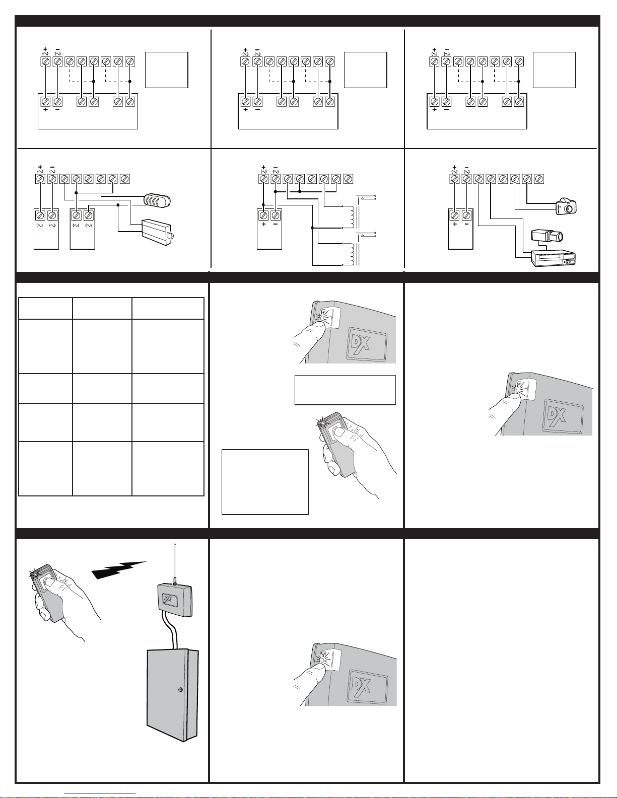
1. PRESS PROGRAM BUTTON FOR THE
DESIRED CHANNEL AND HOLD FOR ABOUT
TWO SECONDS UNTIL INDICATOR LIGHTS
THEN RELEASE.
2. COUNT THE NUMBER OF INDICATOR BLINKS,
THIS IS THE TOTAL NUMBER OF
TRANSMITTERS PROGRAMMED INTO THAT
CHANNEL.
PUSH UNTIL
INDICATOR LIGHTS
NOTE: DO NOT CONTINUE TO PRESS
BUTTON OR MEMORY WILL BE ERASED
1. ACTIVATE EACH TRANSMITTER,
ONE AT AT TIME.
2. LISTEN FOR RELAY CLICK IN
THE RECEIVER.
3. VERIFY THAT THE DEVICE CONNECTED
TO THE RECEIVER RESPONDS AND THAT
THE PROPER CHANNEL ACTIVATES.
4. TEST PORTABLE TRANSMITTERS IN
VARIOUS LOCATIONS TO DETERMINE
SYSTEM PERFORMANCE.
1. PRESS PROGRAM BUTTON
FOR THE CHANNEL TO ERASE
AND CONTINUE TO HOLD IT
THROUGH THE COUNT OF TH
E
TRANSMITTERS
.
2. CONTINUE TO HOLD TH
E
BUTTON AFTER THE COUNT
UNTI
L THE INDICATOR BLINKS
ONCE FOR CHANNEL ONE,
TWICE FOR CHANNEL TWO
(ABOUT FIVE SECONDS
AFTER THE COUNT).
3. ALL TRANSMITTERS
PROGRAMMED INTO
THAT CHANNE
L
WILL BE ERASED.
PUSH AND HOLD BUTTON
FOR FIVE SECONDS AFTER
THE TRANSMITTER COUNT
1. PRESS AND RELEASE
PROGRAM BUTTON FOR THE
DESIRED CHANNEL.
2. PROGRAM INDICATOR WILL
LIGHT FOR 3 SECONDS IF
THERE IS ROOM IN THAT
CHANNEL'S MEMORY FOR
ANOTHER TRANSMITTER
(32 TRANSMITTERS MAXIMUM
TOTAL ALLOWED BETWEEN
BOTH CHANNELS IN THE
RECEIVER).
3. WITHIN 3 SECONDS, SEND
SIGNAL FROM TRANSMITTER,
PROGRAM INDICATOR WILL
FLICKER AS SIGNAL IS
RECEIVED.
4. REPEAT THE ABOVE THREE
STEPS FOR EACH
ADDITIONAL TRANSMITTER.
MULTI-CHANNEL
TRANSMITTER NOTE
:
EACH RECEIVER CHANNEL CAN
ONLY BE PROGRAMMED TO
ACTIVATE FROM A SINGLE
BUTTON ON A MULTI-CHANNEL
TRANSMITTER. LEARNING THE
SAME BUTTON INTO BOTH
CHANNELS ACTIVATES CHANNEL
ONE ONLY
.
AFTER PUSHING THE RECEIVER'S
PROGRAMMING BUTTON, YOU ONLY HAVE
3 SECONDS TO SEND A SIGNAL BEFOR
E
PROGRAMMING MODE STOPS
BUTTON AND INDICATOR FUNCTIONS
FUNCTION
NORMAL
OPERATION
PROGRAMMING
MEMORY
CHECKING
MEMORY
ERASING
MEMORY
PROGRAM
BUTTON
RELEASES
LATCHED RELAY
FOR CHANNEL
1 OR 2
PRESS AND
RELEASE FOR
CHANNEL 1 OR 2
PRESS FOR
CHANNEL 1 OR 2
UNTIL BLINK AND
RELEASE
FOR CHANNEL 1
OR 2, PRESS AND
HOLD THROUGH
THE COUNT AND
HOLD FOR 5
SECONDS MORE
PROGRAM
INDICATOR
LIGHTS WHEN
TRANSMITTER
IS RECEIVED,
FLASHES WHEN
INTERFERENCE IS
RECEIVED
LIGHTS FOR 3
SECONDS FOR
PROGRAMMING
BLINKS THE NUMBER
OF TRANSMITTERS IN
CHANNEL MEMORY
AFTER BLINKING
COUNT. A PAUSE
THEN A SINGLE
BLINK AS MEMORY
IS ERASED (DOUBLE
BLINK ON CHANNEL 2)
SYSTEM TESTING ERASING MEMORY LINEAR LIMITED WARRANTY
PROGRAMMING MEMORY CHECKING MEMORY
This Linear product is warranted against defects in material and workmanship for
twelve (12) months. The Warranty Expiration Date is labeled on the product. This
warranty extends only to wholesale customers who buy direct from Linear or
through Linear’s normal distribution channels. Linear does not warrant this product
to consumers. Consumers should inquire from their selling dealer as to the nature
of the dealer’s warranty, if any. There are no obligations or liabilities on the part of
Linear Corporation for consequential damages arising out of or in connection
with use or performance of this product or other indirect damages with respect
to loss of property, revenue, or prot, or cost of removal, installation, or
reinstallation. All implied warranties, including implied warranties for merchantability
and implied warranties for tness, are valid only until Warranty Expiration Date as
labeled on the product. This Linear Corporation Warranty is in lieu of all other
warranties express or implied.
All products retur ned for warranty service require a Return Product Authorization
Number (RPA#). Contact Linear Technical Service at 1-800-421-1587 for an RPA#
and other important details.
Linear radio controls provide a reliable communications link and ll an important need
in portable wireless signalling. However, there are some limitations which must be
observed.
• For U.S. installations only: The radios are required to comply with FCC Rules and
Regulations as Part 15 devices. As such, they have limited transmitter power and
therefore limited range.
• A receiver cannot respond to more than one transmitted signal at a time and may
be blocked by radio signals that occur on or near their operating frequencies,
regardless of code settings.
• Changes or modications to the device may void FCC compliance.
• Infrequently used radio links should be tested regularly to protect against
undetected interference or fault.
• A general knowledge of radio and its vagaries should be gained prior to acting as
a wholesale distributor or dealer, and these facts should be communicated to the
ultimate users.
Copyright © 2002 Linear Corporation 220464 A
IMPORTANT !!!
 Loading...